EP3409965B9 - Power transmission device - Google Patents
Power transmission device Download PDFInfo
- Publication number
- EP3409965B9 EP3409965B9 EP17744268.8A EP17744268A EP3409965B9 EP 3409965 B9 EP3409965 B9 EP 3409965B9 EP 17744268 A EP17744268 A EP 17744268A EP 3409965 B9 EP3409965 B9 EP 3409965B9
- Authority
- EP
- European Patent Office
- Prior art keywords
- clutch
- side clutch
- clutch discs
- driving
- discs
- Prior art date
- Legal status (The legal status is an assumption and is not a legal conclusion. Google has not performed a legal analysis and makes no representation as to the accuracy of the status listed.)
- Active
Links
- 230000005540 biological transmission Effects 0.000 title description 12
- 230000000694 effects Effects 0.000 description 4
- 230000033001 locomotion Effects 0.000 description 4
- 230000007935 neutral effect Effects 0.000 description 3
- 230000002159 abnormal effect Effects 0.000 description 2
- 238000000926 separation method Methods 0.000 description 1
Images


Classifications
-
- F—MECHANICAL ENGINEERING; LIGHTING; HEATING; WEAPONS; BLASTING
- F16—ENGINEERING ELEMENTS AND UNITS; GENERAL MEASURES FOR PRODUCING AND MAINTAINING EFFECTIVE FUNCTIONING OF MACHINES OR INSTALLATIONS; THERMAL INSULATION IN GENERAL
- F16D—COUPLINGS FOR TRANSMITTING ROTATION; CLUTCHES; BRAKES
- F16D13/00—Friction clutches
- F16D13/22—Friction clutches with axially-movable clutching members
- F16D13/38—Friction clutches with axially-movable clutching members with flat clutching surfaces, e.g. discs
- F16D13/52—Clutches with multiple lamellae ; Clutches in which three or more axially moveable members are fixed alternately to the shafts to be coupled and are pressed from one side towards an axially-located member
- F16D13/54—Clutches with multiple lamellae ; Clutches in which three or more axially moveable members are fixed alternately to the shafts to be coupled and are pressed from one side towards an axially-located member with means for increasing the effective force between the actuating sleeve or equivalent member and the pressure member
- F16D13/56—Clutches with multiple lamellae ; Clutches in which three or more axially moveable members are fixed alternately to the shafts to be coupled and are pressed from one side towards an axially-located member with means for increasing the effective force between the actuating sleeve or equivalent member and the pressure member in which the clutching pressure is produced by springs only
-
- F—MECHANICAL ENGINEERING; LIGHTING; HEATING; WEAPONS; BLASTING
- F16—ENGINEERING ELEMENTS AND UNITS; GENERAL MEASURES FOR PRODUCING AND MAINTAINING EFFECTIVE FUNCTIONING OF MACHINES OR INSTALLATIONS; THERMAL INSULATION IN GENERAL
- F16D—COUPLINGS FOR TRANSMITTING ROTATION; CLUTCHES; BRAKES
- F16D13/00—Friction clutches
- F16D13/04—Friction clutches with means for actuating or keeping engaged by a force derived at least partially from one of the shafts to be connected
-
- F—MECHANICAL ENGINEERING; LIGHTING; HEATING; WEAPONS; BLASTING
- F16—ENGINEERING ELEMENTS AND UNITS; GENERAL MEASURES FOR PRODUCING AND MAINTAINING EFFECTIVE FUNCTIONING OF MACHINES OR INSTALLATIONS; THERMAL INSULATION IN GENERAL
- F16D—COUPLINGS FOR TRANSMITTING ROTATION; CLUTCHES; BRAKES
- F16D13/00—Friction clutches
- F16D13/22—Friction clutches with axially-movable clutching members
- F16D13/38—Friction clutches with axially-movable clutching members with flat clutching surfaces, e.g. discs
- F16D13/52—Clutches with multiple lamellae ; Clutches in which three or more axially moveable members are fixed alternately to the shafts to be coupled and are pressed from one side towards an axially-located member
- F16D13/54—Clutches with multiple lamellae ; Clutches in which three or more axially moveable members are fixed alternately to the shafts to be coupled and are pressed from one side towards an axially-located member with means for increasing the effective force between the actuating sleeve or equivalent member and the pressure member
- F16D13/56—Clutches with multiple lamellae ; Clutches in which three or more axially moveable members are fixed alternately to the shafts to be coupled and are pressed from one side towards an axially-located member with means for increasing the effective force between the actuating sleeve or equivalent member and the pressure member in which the clutching pressure is produced by springs only
- F16D2013/565—Clutches with multiple lamellae ; Clutches in which three or more axially moveable members are fixed alternately to the shafts to be coupled and are pressed from one side towards an axially-located member with means for increasing the effective force between the actuating sleeve or equivalent member and the pressure member in which the clutching pressure is produced by springs only with means for releasing the clutch pressure in case of back torque
Definitions
- the present invention relates to a power transmitting apparatus for selectively transmitting the rotational power of an input member to an output member or cutting-off the rotational power.
- the power transmitting apparatus for a motorcycle is intended to selectively perform transmission or cutting-off of the driving power of an engine to a transmission and a driving wheel and comprises an input member connected to an engine-side, an output member connected to a transmission and a driving wheel-side, and a clutch member connected to the output member.
- the driving power can be transmitted by press-contacting a plurality of driving-side clutch discs and driven-side clutch discs each other or cut-off by releasing the press-contacting force acting on the driving-side clutch discs and driven-side clutch discs.
- the power transmitting apparatus of the prior art comprises, as disclosed in Patent Document 1 below, a clutch housing rotatable together with an input member and mounted thereon a plurality of driving-side clutch discs, a plurality of driven-side clutch discs arranged alternately between the driving-side clutch discs, a clutch member connected to an output member, a pressure member mounted on the clutch member axially movably relative to the clutch member for press-contacting the driving-side clutch discs and the driven-side clutch discs each other and for releasing the press-contacting force acting on them in accordance with axial movement relative to the clutch member and is structured so as to transmit or cut-off the rotational power inputted to the input member to or from the output member.
- Patent Document 2 Another power transmitting apparatus of the prior art has been disclosed in e.g. Patent Document 2 below.
- This power transmitting apparatus comprises a press-contact assisting cam means for increasing the press-contacting force between the driving-side clutch discs and the driven-side clutch discs by approach of the pressure member and the clutch member toward each other when the pressure member and the clutch member are relatively rotated under a condition in which the rotational power inputted to the input member can be transmitted to the output member; and a back-torque limiting cam means for releasing the press-contacting force between the driving-side clutch discs and the driven-side clutch discs due to separation of the pressure member and the clutch member caused by relative rotation of them when the rotation speed of the output member exceed that of the input member.
- Another power transmitting apparatus is known from Patent Document 3.
- the power transmission device disclosed in Patent Document 3 can suppress the rotational vibrations by suppressing rotation of the pressure member relative to the clutch member since the power transmitting apparatus comprises slide-suppressing members for applying sliding resistance to the clutch member when the pressure member is rotated relative to the clutch member.
- an object of the present invention to provide a power transmitting apparatus which can suppress interference between the cam surfaces or abutment surfaces of the clutch member and the pressure member even when the sticking torque would be caused between the driving-side clutch discs and the driven-side clutch discs.
- a power transmitting apparatus for transmitting a rotational power inputted to an input member to an output member or cutting-off the rotational power by press-contacting a plurality of driving-side clutch discs and a plurality of driven-side clutch discs each other or releasing the press-contacting force between them comprising a clutch housing rotatable together with the input member and mounted thereon the driving-side clutch discs; a clutch member connected to the output member and mounted thereon the driven-side clutch discs arranged between the driving-side clutch discs of the clutch housing alternately therewith; a pressure member for press-contacting the driving-side clutch discs and the driven-side clutch discs each other or releasing the press-contacting force therebetween; clutch springs applying an urging force for press-contacting the driving-side clutch discs and the driven-side clutch discs each other; and a press-contact assisting cam means for increasing the press-contacting force acting on the driving-side clutch discs and the
- the present invention of claim 2 is a power transmitting apparatus of claim 1 further comprising a back-torque limiting cam means for releasing the press-contacting force acting on the driving-side clutch discs and the driven-side clutch discs by causing relative rotation of the pressure member and the clutch member and separating them from each other when a rotational speed of the output member exceeds that of the input member.
- the power transmitting apparatus further comprises clutch springs applying an urging force for press-contacting the driving-side clutch discs and the driven-side clutch discs each other and the clutch springs can also apply the resisting force
- the clutch springs can perform a function of suppressing interference between the cam surfaces or abutment surfaces of the clutch member and the pressure member in addition to a function of press-contacting the driving-side clutch discs and the driven-side clutch discs each other.
- the resisting force can be attained by the torsional rigidity or sliding resistance of the clutch spring, it is possible to more easily apply the resisting force against the relative rotation between the clutch member and the pressure member.
- the power transmitting apparatus further comprises holding parts for covering and holding the outer surface of the clutch springs and the holding parts restrict torsion of the clutch springs caused by relative rotation between the clutch member and the pressure member, it is possible to more surely apply the resisting force against the relative rotation between the clutch member and the pressure member.
- the power transmitting apparatus further comprises a back-torque limiting cam means for releasing the press-contacting force acting on the driving-side clutch discs and the driven-side clutch discs by causing relative rotation of the pressure member and the clutch member and separating them from each other when a rotational speed of the output member exceeds that of the input member, it is possible to exhibit effects obtained by the press-contact assisting cam means or the back-torque limiting cam means and thus to effectively suppress interference between the cam surfaces or abutment surfaces of the clutch member and the pressure member even when the sticking torque would be caused between the driving-side clutch discs and the driven-side clutch discs.
- a power transmitting apparatus of the present embodiment is mounted on a vehicle such as a motorcycle to selectively transmit or cut off the driving power of an engine to a transmission or driving wheel.
- the power transmitting apparatus mainly comprises a clutch housing 2 which is connected to a gear 1 as an input member, a clutch member 4 connected to a shaft 3 as an output member, a pressure member 5 mounted on the clutch member 4, driving-side clutch discs 6 mounted on the clutch housing 2, driven-side clutch discs 7 mounted on the clutch member 4, and a mount member 10 on which clutch springs 8 are mounted.
- a reference character S denotes a damper.
- the gear 1 can be rotated around the shaft 3 by the driving power (rotational power) transmitted from the engine and connected to the clutch housing 2 via rivets R etc.
- the clutch housing 2 is formed as a cylindrical casing opened at its right-hand end of Fig.1 and a plurality of driving-side clutch discs 6 are mounted on the inner circumference of the clutch housing 2.
- Each of the driving-side clutch discs 6 comprises a substantially annular plate engaging with a spline formed on the inner circumference of the clutch housing 2 and is adapted to be rotated together with the clutch housing 2 and axially slidable (left-hand and right-hand directions seen in Fig. 1 ) along the spline.
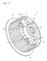
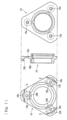
- the clutch member 4 is arranged within the clutch housing 2 and comprises, as shown in Figs. 3 and 4 , a cam surface 4a forming one part of a press-contact assisting cam means described later, a spline 4b formed on the outer circumference of the clutch member 4, a flanged part 4c upstanding from one end of the clutch member 4, a central bore 4d formed at the center of the clutch member 4, and apertures 4e through which the clutch springs 8 mounted on the pressure member 5 can be passed.
- the central bore 4d is formed on its inner circumference with a spline engaging with a spline formed on the shaft 3 so as to be rotated together with the shaft 3.
- the spline 4b is formed on a substantially whole region of the outer circumference of the clutch member 4 and the driven-side clutch discs 7 are mounted thereon via spline engagement.
- This enables the driven-side clutch discs 7 to be axially moved relative to the clutch member 4 but to be prevented from being rotated relative to the clutch member 4.
- the driven-side clutch discs 7 is configured to rotate together with the clutch member 4.
- the driven-side clutch discs 7 are arranged between the driving-side clutch discs 6 of the clutch housing 2 alternately therewith and mutually adjacent driving-side clutch discs 6 and driven-side clutch discs 7 are connected and released by press-contacting and releasing them.
- the driving-side clutch discs 6 and the driven-side clutch discs 7 are alternately arranged in a laminated state between the flanged part 4c of the clutch member 4 and the flanged part 5b of the pressure member 5 and allowed to be slid axially of the clutch member 4. Accordingly, they are press-contacted each other when the flanged part 4c and the flanged part 5b are moved toward each other to transmit rotational power of the clutch housing 2 to the shaft 3 via the clutch member 4 and the press-contacting force are released when the flanged part 4c and the flanged part 5b are moved apart from each other to cut-off transmission of the rotational power to the shaft 3.
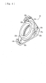
- the pressure member 5 is a member to be assembled to the clutch member 4 and comprises, as shown in Figs. 5 and 6 , a cam surface 5a forming one part of the press-contact assisting cam means described later, the flanged part 5b formed on the periphery of the pressure member 5, boss parts 5c and a central aperture 5d.
- the laminated driving-side clutch discs 6 and the driven-side clutch discs 7 are positioned between the flanged part 5b of the pressure member 5 and the flanged part 4c of the clutch member 4 under an assembled state of the pressure member 5 and the clutch member 4 with passing the clutch member 4 into the central aperture 5d of the pressure member 5.
- Each boss part 5c formed on the pressure member 5 is formed as a projected part toward the clutch member 4 (right-hand side of Fig. 1 ) and formed with a mount aperture 5ca into which a clutch bolt B is screwed.
- the mount member 10 is mounted on the projected ends of the boss parts 5c by fastening the clutch bolts B to the mount apertures 5ca.
- the mount member 10 is formed with apertures 10a through which the clutch bolts B are inserted and holding parts 10b formed around the apertures 10a to hold the outer surfaces of one ends of the clutch springs 8.
- the other ends of the clutch springs 8 are held by any parts (circumferential parts of the apertures 4e in the present embodiment) of the clutch member 4 to apply an urging force to the clutch member 4.
- the clutch member 4 is normally urged toward the left in Fig. 1 .
- An operating member 9 is connected to a bearing of the mount member 10 and accordingly the pressure member 5 can be moved to a direction (the left in Fig. 1 ) in which the pressure member 5 is moved apart away from the clutch member 4 against the urging force of the clutch springs 8 with a driver operating an operation means such as a clutch lever (not shown).
- the clutch member 4 is constituted so that it can press-contact or release the driving-side clutch discs 6 and the driven-side clutch discs 7 in accordance with the axial movement of the pressure member 5.
- the clutch member 4 and the pressure member 5 are formed with a cam surface 4a and a cam surface 5a comprising predetermined inclined surfaces respectively which are adapted to be opposed each other to form a press-contact assisting cam means.
- the press-contact assisting cam means functions to increase the press-contacting force between the driving-side clutch discs 6 and the driven-side clutch discs 7 due to approach of these clutch discs 6, 7 caused by relative rotation of the pressure member 5 and the clutch member 4 when the rotational power inputted to the clutch housing 2 (input member) can be transmitted to the shaft 3 (output member).
- sticking torque used in the present application is defined as a torque inputted to the pressure member 5 due to transmission of power via viscosity of oil present between the driving-side clutch discs 6 and the driven-side clutch discs 7 under conditions in which a vehicle is in a stopped state under a transmission gear position being in the "neutral” state as well as the clutch is in the "cut-off' state (the clutch member 4 and the pressure member 5 being operated to the separated state).
- the sticking torque in the present application is a torque inputted to the pressure member 5 and according to the present embodiment, the sticking torque inputted to the pressure member 5 is that generated between three clutch discs (i.e. one driven-side clutch disc 7 (leftmost clutch disc 7 in Fig. 1 ) fitted with the pressure member 5 and two driving-side clutch discs 6 sandwiching said one driven-side clutch disc 7).
- the sticking torque of the present application is that generated between five clutch discs (i.e. said two driven-side clutch discs 7 fitted with the pressure member 5 and three driving-side clutch discs 6 sandwiching and contacting with said two driven-side clutch discs 7).
- the resisting force larger than the sticking torque can be generated between the clutch member 4 and the pressure member 5 under conditions in which a vehicle is in a stopped state under a transmission gear position being in the "neutral” state as well as the clutch is in the "cut-off' state (the clutch member 4 and the pressure member 5 being operated to the separated state), it is possible to suppress generation of the relative rotation (phase rotation) between the clutch member 4 and the pressure member 5 as well as to prevent the interference of the cam surface 4a of the clutch member 4 and the cam surface 5a of the pressure member 5 which would be caused by approach of them. Accordingly, it is possible to reduce the magnitude of abnormal noise (impact noise) caused by the interference between the cam surface 4a of the clutch member 4 and the cam surface 5a of the pressure member 5 when the clutch is operated to the cut-off state.
- abnormal noise impact noise
- the clutch springs 8 for applying urging force to press-contact the driving-side clutch discs 6 and the driven-side clutch discs 7 each other can apply the resisting force (i.e. resisting force set larger than the sticking torque between the driving-side clutch discs 6 and the driven-side clutch discs 7). More specifically, the resisting force can be increased by increasing the torsional rigidity (the spring constant or the wire diameter) or the sliding resistance of the clutch springs 8 relative to their holding members.
- the sticking torque cannot be absorbed in the cam clearance D in a power transmitting apparatus of the prior art.
- the sticking torque can be absorbed in the cam clearance D when the spring constant of the clutch springs 8 is increased ( Fig. 10(b) ) and when the wire diameter of the clutch springs 8 is increased ( Fig. 10(c) ).
- the power transmitting apparatus is provided with holding parts 10b for covering and holding the outer surface of the clutch springs 8.
- the holding parts 10b restrict torsion of the clutch springs 8 caused by relative rotation between the clutch member 4 and the pressure member 5. That is, each holding part 10b for holding one end of the clutch spring 8 is formed with a wall extending axially of the clutch spring 8 and having a predetermined height for covering a portion of the outer surface of the clutch spring 8.
- the sticking torque can be absorbed in the cam clearance D as shown in Fig. 10(d) .
- the holding parts 10b may be arranged at other ends of the clutch springs 8 (i.e. at a clutch member 4 side).
- the present invention since application of a resisting force for resisting relative rotation between the clutch member 4 and the pressure member 5 can be attained and the magnitude of the resisting force is set larger than a sticking torque between the driving-side clutch discs 6 and the driven-side clutch discs 7, it is possible to suppress interference between the cam surfaces or abutment surfaces of the clutch member and the pressure member (cam surfaces 4a, 5a in the present embodiment) even when the sticking torque would be caused between the driving-side clutch discs and the driven-side clutch discs.
- the power transmitting apparatus comprises clutch springs 8 applying an urging force for press-contacting the driving-side clutch discs 6 and the driven-side clutch discs 7 each other and the clutch springs 8 can also apply the resisting force
- the clutch springs 8 can perform a function of suppressing interference between the cam surfaces or abutment surfaces of the clutch member 4 and the pressure member 5 (cam surfaces 4a, 5a in the present embodiment) in addition to a function of press-contacting the driving-side clutch discs 6 and the driven-side clutch discs 7 each other.
- the resisting force can be also obtained by the torsional rigidity of the clutch springs 8 or the sliding resistance of the clutch springs 8, it is possible to more easily apply the resising force against relative rotation between the clutch member 4 and the pressure member 5.
- the power transmitting apparatus comprises holding parts 10b for covering and holding the outer surface of the clutch springs 8 and the holding parts 10b restrict torsion of the clutch springs 8 caused by relative rotation between the clutch member 4 and the pressure member 5, it is possible to more surely apply the resisting force against the relative rotation between the clutch member 4 and the pressure member 5.
- the power transmitting apparatus comprises a press-contact assisting cam means (formed by the cam surfaces 4a, 5a) for increasing the press-contacting force between the driving-side clutch discs 6 and the driven-side clutch discs 7 due to approaching motion caused by relative rotation of the pressure member 5 and the clutch member 4 under a state in which the rotational power inputted to the input member (gear 1) can be transmitted to the output member (shaft 3), it is possible to exhibit effects obtained by the press-contact assisting cam means and to effectively suppress interference between the cam surfaces or abutment surfaces of the clutch member 4 and the pressure member 5 (cam surfaces 4a, 5a in the present embodiment) even when the sticking torque would be caused between the driving-side clutch discs 6 and the driven-side clutch discs 7.
- a press-contact assisting cam means formed by the cam surfaces 4a, 5a
- a back-torque limiting cam means for releasing the press-contacting force between the driving-side clutch discs 6 and the driven-side clutch discs 7 due to separating motion caused by relative rotation of the pressure member 5 and the clutch member 4 under a state in which the rotation speed of the output member (shaft 3) exceeds that of the input member (gear 1) in addition to or in place of the press-contact assisting cam means (formed by the cam surfaces 4a, 5a).
- the present invention is not limited to such an embodiment but by the appended claims.
- the present invention may be applied to various kinds of multiple disc clutch type power transmitting apparatus used for automobiles, three-wheeled or four-wheeled buggies or machines for general use other than motorcycles.
- the present invention can be applied to any power transmitting apparatus having other different appearances or additional functions if the power transmitting apparatus can apply resisting force against relative rotation between the clutch member and the pressure member and the resisting force is set larger than the sticking torque between the driving-side clutch discs and the driven-side clutch discs.
Description
- The present invention relates to a power transmitting apparatus for selectively transmitting the rotational power of an input member to an output member or cutting-off the rotational power.
- In general, the power transmitting apparatus for a motorcycle is intended to selectively perform transmission or cutting-off of the driving power of an engine to a transmission and a driving wheel and comprises an input member connected to an engine-side, an output member connected to a transmission and a driving wheel-side, and a clutch member connected to the output member. The driving power can be transmitted by press-contacting a plurality of driving-side clutch discs and driven-side clutch discs each other or cut-off by releasing the press-contacting force acting on the driving-side clutch discs and driven-side clutch discs.
- More specifically, the power transmitting apparatus of the prior art comprises, as disclosed in
Patent Document 1 below, a clutch housing rotatable together with an input member and mounted thereon a plurality of driving-side clutch discs, a plurality of driven-side clutch discs arranged alternately between the driving-side clutch discs, a clutch member connected to an output member, a pressure member mounted on the clutch member axially movably relative to the clutch member for press-contacting the driving-side clutch discs and the driven-side clutch discs each other and for releasing the press-contacting force acting on them in accordance with axial movement relative to the clutch member and is structured so as to transmit or cut-off the rotational power inputted to the input member to or from the output member. - In addition, another power transmitting apparatus of the prior art has been disclosed in
e.g. Patent Document 2 below. This power transmitting apparatus comprises a press-contact assisting cam means for increasing the press-contacting force between the driving-side clutch discs and the driven-side clutch discs by approach of the pressure member and the clutch member toward each other when the pressure member and the clutch member are relatively rotated under a condition in which the rotational power inputted to the input member can be transmitted to the output member; and a back-torque limiting cam means for releasing the press-contacting force between the driving-side clutch discs and the driven-side clutch discs due to separation of the pressure member and the clutch member caused by relative rotation of them when the rotation speed of the output member exceed that of the input member. Another power transmitting apparatus is known from Patent Document 3. The power transmission device disclosed in Patent Document 3 can suppress the rotational vibrations by suppressing rotation of the pressure member relative to the clutch member since the power transmitting apparatus comprises slide-suppressing members for applying sliding resistance to the clutch member when the pressure member is rotated relative to the clutch member. -
- Patent Document 1:
JP 2010-223296 A - Patent Document 2:
JP 2005-325993 A - Patent Document 3:
EP 2 799 734 A1 - However, there are following problems in the power transmitting apparatus of the prior art.
Since that there would be caused a "lever feedback" phenomenon when the power transmitting apparatus is provided with both the press-contact assisting cam means and back-torque limiting cam means, it has been proposed a power transmitting apparatus only provided with the press-contact assisting cam means without the back-torque limiting cam means. However, since a relatively large clearance is required between the cam surfaces or abutment surfaces of the clutch member and the pressure member in this case due to a reason of assembly, there is a problem that abnormal noise would be caused due to interference of the abutment surfaces when a relative rotation (phase rotation) is caused between the clutch member and the pressure member by generation of the sticking torque between the driving-side clutch discs and the driven-side clutch discs when the power transmission is cut-off (clutched-off). Although such a problem is remarkable in a structure in which only the press-contact assisting cam means is installed without the back-torque limiting cam means, similar problems will be caused in structures in which both the press-contact assisting cam means and the back-torque limiting cam means are installed and none of the press-contact assisting cam means and the back-torque limiting cam means is installed if the relatively large clearance is formed between the cam surfaces or abutment surfaces of the clutch member and the pressure member. - It is, therefore, an object of the present invention to provide a power transmitting apparatus which can suppress interference between the cam surfaces or abutment surfaces of the clutch member and the pressure member even when the sticking torque would be caused between the driving-side clutch discs and the driven-side clutch discs.
- For achieving the object of the present invention above, there is provided, according to
claim 1 of the present invention, a power transmitting apparatus for transmitting a rotational power inputted to an input member to an output member or cutting-off the rotational power by press-contacting a plurality of driving-side clutch discs and a plurality of driven-side clutch discs each other or releasing the press-contacting force between them comprising a clutch housing rotatable together with the input member and mounted thereon the driving-side clutch discs; a clutch member connected to the output member and mounted thereon the driven-side clutch discs arranged between the driving-side clutch discs of the clutch housing alternately therewith; a pressure member for press-contacting the driving-side clutch discs and the driven-side clutch discs each other or releasing the press-contacting force therebetween; clutch springs applying an urging force for press-contacting the driving-side clutch discs and the driven-side clutch discs each other; and a press-contact assisting cam means for increasing the press-contacting force acting on the driving-side clutch discs and the driven-side clutch discs by causing relative rotation of the pressure member and the clutch member and bringing them close to each other when the rotational power inputted to the input member can be transmitted to the output member wherein the clutch springs apply a resisting force for resisting relative rotation between the clutch member and the pressure member when the clutch member and the pressure member are operated to the separated state and the magnitude of the resisting force is set larger than a sticking torque between the driving-side clutch discs and the driven-side clutch discs, wherein the resisting force is attained by the torsional rigidity from the spring constant of the clutch spring or torsional rigidity from the wire diameter of the clutch spring or sliding resistance of the clutch spring and wherein the power apparatus further comprising holding parts for covering and holding the outer surfaces of the clutch springs and wherein the holding parts restrict torsion of the clutch springs caused by relative rotation between the clutch member and the pressure member. - The present invention of
claim 2 is a power transmitting apparatus ofclaim 1 further comprising a back-torque limiting cam means for releasing the press-contacting force acting on the driving-side clutch discs and the driven-side clutch discs by causing relative rotation of the pressure member and the clutch member and separating them from each other when a rotational speed of the output member exceeds that of the input member. - According to the present invention of
claim 1, since application of a resisting force for resisting relative rotation between the clutch member and the pressure member can be attained and the magnitude of the resisting force is set larger than a sticking torque between the driving-side clutch discs and the driven-side clutch discs, it is possible to suppress interference between the cam surfaces or abutment surfaces of the clutch member and the pressure member even when the sticking torque would be caused between the driving-side clutch discs and the driven-side clutch discs. - Furthermore, since the power transmitting apparatus further comprises clutch springs applying an urging force for press-contacting the driving-side clutch discs and the driven-side clutch discs each other and the clutch springs can also apply the resisting force, the clutch springs can perform a function of suppressing interference between the cam surfaces or abutment surfaces of the clutch member and the pressure member in addition to a function of press-contacting the driving-side clutch discs and the driven-side clutch discs each other.
- Additionally, since the resisting force can be attained by the torsional rigidity or sliding resistance of the clutch spring, it is possible to more easily apply the resisting force against the relative rotation between the clutch member and the pressure member.
- Furthermore, since the power transmitting apparatus further comprises holding parts for covering and holding the outer surface of the clutch springs and the holding parts restrict torsion of the clutch springs caused by relative rotation between the clutch member and the pressure member, it is possible to more surely apply the resisting force against the relative rotation between the clutch member and the pressure member.
- According to the present invention of
claim 2, since the power transmitting apparatus further comprises a back-torque limiting cam means for releasing the press-contacting force acting on the driving-side clutch discs and the driven-side clutch discs by causing relative rotation of the pressure member and the clutch member and separating them from each other when a rotational speed of the output member exceeds that of the input member, it is possible to exhibit effects obtained by the press-contact assisting cam means or the back-torque limiting cam means and thus to effectively suppress interference between the cam surfaces or abutment surfaces of the clutch member and the pressure member even when the sticking torque would be caused between the driving-side clutch discs and the driven-side clutch discs. -
- [
Fig. 1 ] A longitudinal sectional view of a power transmitting apparatus according to an embodiment of the present invention; - [
Fig. 2 ] A front elevation view showing the power transmitting apparatus ofFig. 1 ; - [
Fig. 3 ] A three-aspect view showing a clutch member of the power transmitting apparatus ofFig. 1 ; - [
Fig. 4 ] A perspective view showing the clutch member of the power transmitting apparatus ofFig. 1 ; - [
Fig. 5 ] A three-aspect view showing a pressure member of the power transmitting apparatus ofFig. 1 ; - [
Fig. 6 ] A perspective view showing the pressure member of the power transmitting apparatus ofFig. 1 ; - [
Fig. 7 ] A three-aspect view showing a mount member of the power transmitting apparatus ofFig. 1 ; - [
Fig. 8 ] A perspective view showing the mount member of the power transmitting apparatus ofFig. 1 ; - [
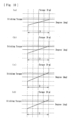
Fig. 9 ] A schematic view showing an action of the press-contact assisting cam means of the power transmitting apparatus ofFig. 1 ; and - [
Fig. 10 ] Experimental data showing technological advantages of the power transmitting apparatus of the present invention. - A preferable embodiment of the present invention will be hereinafter described with reference to the accompanying drawings.
- A power transmitting apparatus of the present embodiment is mounted on a vehicle such as a motorcycle to selectively transmit or cut off the driving power of an engine to a transmission or driving wheel. As shown in
Figs. 1 to 8 , the power transmitting apparatus mainly comprises aclutch housing 2 which is connected to agear 1 as an input member, aclutch member 4 connected to a shaft 3 as an output member, apressure member 5 mounted on theclutch member 4, driving-side clutch discs 6 mounted on theclutch housing 2, driven-side clutch discs 7 mounted on theclutch member 4, and amount member 10 on whichclutch springs 8 are mounted. A reference character S denotes a damper. - The
gear 1 can be rotated around the shaft 3 by the driving power (rotational power) transmitted from the engine and connected to theclutch housing 2 via rivets R etc. Theclutch housing 2 is formed as a cylindrical casing opened at its right-hand end ofFig.1 and a plurality of driving-side clutch discs 6 are mounted on the inner circumference of theclutch housing 2. Each of the driving-side clutch discs 6 comprises a substantially annular plate engaging with a spline formed on the inner circumference of theclutch housing 2 and is adapted to be rotated together with theclutch housing 2 and axially slidable (left-hand and right-hand directions seen inFig. 1 ) along the spline. - The
clutch member 4 is arranged within theclutch housing 2 and comprises, as shown inFigs. 3 and4 , acam surface 4a forming one part of a press-contact assisting cam means described later, aspline 4b formed on the outer circumference of theclutch member 4, a flangedpart 4c upstanding from one end of theclutch member 4, acentral bore 4d formed at the center of theclutch member 4, and apertures 4e through which theclutch springs 8 mounted on thepressure member 5 can be passed. Thecentral bore 4d is formed on its inner circumference with a spline engaging with a spline formed on the shaft 3 so as to be rotated together with the shaft 3. - The
spline 4b is formed on a substantially whole region of the outer circumference of theclutch member 4 and the driven-side clutch discs 7 are mounted thereon via spline engagement. This enables the driven-side clutch discs 7 to be axially moved relative to theclutch member 4 but to be prevented from being rotated relative to theclutch member 4. Thus, the driven-side clutch discs 7 is configured to rotate together with theclutch member 4. In addition, the driven-side clutch discs 7 are arranged between the driving-side clutch discs 6 of theclutch housing 2 alternately therewith and mutually adjacent driving-side clutch discs 6 and driven-side clutch discs 7 are connected and released by press-contacting and releasing them. - The driving-side clutch discs 6 and the driven-
side clutch discs 7 are alternately arranged in a laminated state between the flangedpart 4c of theclutch member 4 and the flangedpart 5b of thepressure member 5 and allowed to be slid axially of theclutch member 4. Accordingly, they are press-contacted each other when theflanged part 4c and theflanged part 5b are moved toward each other to transmit rotational power of theclutch housing 2 to the shaft 3 via theclutch member 4 and the press-contacting force are released when the flangedpart 4c and the flangedpart 5b are moved apart from each other to cut-off transmission of the rotational power to the shaft 3. - The
pressure member 5 is a member to be assembled to theclutch member 4 and comprises, as shown inFigs. 5 and6 , acam surface 5a forming one part of the press-contact assisting cam means described later, the flangedpart 5b formed on the periphery of thepressure member 5,boss parts 5c and acentral aperture 5d. The laminated driving-side clutch discs 6 and the driven-side clutch discs 7 are positioned between theflanged part 5b of thepressure member 5 and theflanged part 4c of theclutch member 4 under an assembled state of thepressure member 5 and theclutch member 4 with passing theclutch member 4 into thecentral aperture 5d of thepressure member 5. - Each
boss part 5c formed on thepressure member 5 is formed as a projected part toward the clutch member 4 (right-hand side ofFig. 1 ) and formed with a mount aperture 5ca into which a clutch bolt B is screwed. Themount member 10 is mounted on the projected ends of theboss parts 5c by fastening the clutch bolts B to the mount apertures 5ca. As shown inFig. 7 , themount member 10 is formed withapertures 10a through which the clutch bolts B are inserted and holdingparts 10b formed around theapertures 10a to hold the outer surfaces of one ends of theclutch springs 8. - On the other hand, the other ends of the
clutch springs 8 are held by any parts (circumferential parts of theapertures 4e in the present embodiment) of theclutch member 4 to apply an urging force to theclutch member 4. Thus theclutch member 4 is normally urged toward the left inFig. 1 . Anoperating member 9 is connected to a bearing of themount member 10 and accordingly thepressure member 5 can be moved to a direction (the left inFig. 1 ) in which thepressure member 5 is moved apart away from theclutch member 4 against the urging force of theclutch springs 8 with a driver operating an operation means such as a clutch lever (not shown). - When the
pressure member 5 is moved toward the left inFig. 1 , the press-contacting force between the driving-side clutch discs 6 and the driven-side clutch discs 7 is released and thus transmission of the rotational power inputted to thegear 1 andclutch housing 2 to theclutch member 4 and shaft 3 is cut-off. That is, theclutch member 4 is constituted so that it can press-contact or release the driving-side clutch discs 6 and the driven-sideclutch discs 7 in accordance with the axial movement of thepressure member 5. - As shown in
Figs. 3 to 6 , theclutch member 4 and thepressure member 5 are formed with acam surface 4a and acam surface 5a comprising predetermined inclined surfaces respectively which are adapted to be opposed each other to form a press-contact assisting cam means. The press-contact assisting cam means functions to increase the press-contacting force between the driving-side clutch discs 6 and the driven-sideclutch discs 7 due to approach of theseclutch discs 6, 7 caused by relative rotation of thepressure member 5 and theclutch member 4 when the rotational power inputted to the clutch housing 2 (input member) can be transmitted to the shaft 3 (output member). - As shown in
Fig. 9 , since thepressure member 5 rotates toward an arrow "a" direction relative to theclutch member 4 when the rotational force inputted to the clutch housing 2 (input member) is transmitted to the shaft 3 (output member), it is constituted so that thecam surface 4a and thecam surface 5a are abutted each other and accordingly thepressure member 5 is moved toward an arrow "b" direction by a cam action of thesecam surfaces clutch discs 7. In the present embodiment, surfaces α, β positioned at opposite sides of the cam surfaces 4a, 5a constitute abutment surfaces. - As described later more in detail, it is constituted according to the present embodiment that a force resisting to the relative rotation (phase rotation) between the
clutch member 4 and thepressure member 5 can be obtained and that the resisting force is set larger than the sticking torque between the driving-side clutch discs 6 and the driven-sideclutch discs 7. The term "sticking torque" used in the present application is defined as a torque inputted to thepressure member 5 due to transmission of power via viscosity of oil present between the driving-side clutch discs 6 and the driven-sideclutch discs 7 under conditions in which a vehicle is in a stopped state under a transmission gear position being in the "neutral" state as well as the clutch is in the "cut-off' state (theclutch member 4 and thepressure member 5 being operated to the separated state). - It is afraid that the sticking torque would cause the relative rotation (phase rotation) of the
pressure member 5 relative to theclutch member 4 and accordingly thecam surface 4a of theclutch member 4 would approach thecam surface 5a and cause interference therebetween. That is, when the clutch is cut-off under a condition in which thecam surface 4a and thecam surface 5a are rotated without engaging each other in the neutral state, the relative rotation (phase rotation) of theclutch member 4 and thepressure member 5 would be caused due to difference of their inertia and thus thecam surface 4a and thecam surface 5a would be interfered with each other as shown inFig. 9 . - More specifically, the sticking torque in the present application is a torque inputted to the
pressure member 5 and according to the present embodiment, the sticking torque inputted to thepressure member 5 is that generated between three clutch discs (i.e. one driven-side clutch disc 7 (leftmostclutch disc 7 inFig. 1 ) fitted with thepressure member 5 and two driving-side clutch discs 6 sandwiching said one driven-side clutch disc 7). In place of the illustrated embodiment, assuming that there are two driven-sideclutch discs 7 fitted with thepressure member 5, the sticking torque of the present application is that generated between five clutch discs (i.e. said two driven-sideclutch discs 7 fitted with thepressure member 5 and three driving-side clutch discs 6 sandwiching and contacting with said two driven-side clutch discs 7). - As described later more in detail, according to the present embodiment since the resisting force larger than the sticking torque can be generated between the
clutch member 4 and thepressure member 5 under conditions in which a vehicle is in a stopped state under a transmission gear position being in the "neutral" state as well as the clutch is in the "cut-off' state (theclutch member 4 and thepressure member 5 being operated to the separated state), it is possible to suppress generation of the relative rotation (phase rotation) between theclutch member 4 and thepressure member 5 as well as to prevent the interference of thecam surface 4a of theclutch member 4 and thecam surface 5a of thepressure member 5 which would be caused by approach of them. Accordingly, it is possible to reduce the magnitude of abnormal noise (impact noise) caused by the interference between thecam surface 4a of theclutch member 4 and thecam surface 5a of thepressure member 5 when the clutch is operated to the cut-off state. - According to the present embodiment, it is constituted that the
clutch springs 8 for applying urging force to press-contact the driving-side clutch discs 6 and the driven-sideclutch discs 7 each other can apply the resisting force (i.e. resisting force set larger than the sticking torque between the driving-side clutch discs 6 and the driven-side clutch discs 7). More specifically, the resisting force can be increased by increasing the torsional rigidity (the spring constant or the wire diameter) or the sliding resistance of theclutch springs 8 relative to their holding members. - For example as shown in
Fig. 10(a) , the sticking torque cannot be absorbed in the cam clearance D in a power transmitting apparatus of the prior art. However, according to the power transmitting apparatus of the present embodiment, the sticking torque can be absorbed in the cam clearance D when the spring constant of theclutch springs 8 is increased (Fig. 10(b) ) and when the wire diameter of theclutch springs 8 is increased (Fig. 10(c) ). - In addition, according to the present embodiment, the power transmitting apparatus is provided with holding
parts 10b for covering and holding the outer surface of the clutch springs 8. The holdingparts 10b restrict torsion of theclutch springs 8 caused by relative rotation between theclutch member 4 and thepressure member 5. That is, each holdingpart 10b for holding one end of theclutch spring 8 is formed with a wall extending axially of theclutch spring 8 and having a predetermined height for covering a portion of the outer surface of theclutch spring 8. - When the holding
parts 10b for holding the outer surface of theclutch springs 8 are formed according to the present embodiment, the sticking torque can be absorbed in the cam clearance D as shown inFig. 10(d) . The holdingparts 10b may be arranged at other ends of the clutch springs 8 (i.e. at aclutch member 4 side). - According to the present invention, since application of a resisting force for resisting relative rotation between the
clutch member 4 and thepressure member 5 can be attained and the magnitude of the resisting force is set larger than a sticking torque between the driving-side clutch discs 6 and the driven-sideclutch discs 7, it is possible to suppress interference between the cam surfaces or abutment surfaces of the clutch member and the pressure member (cam surfaces 4a, 5a in the present embodiment) even when the sticking torque would be caused between the driving-side clutch discs and the driven-side clutch discs. - In addition, since the power transmitting apparatus comprises
clutch springs 8 applying an urging force for press-contacting the driving-side clutch discs 6 and the driven-sideclutch discs 7 each other and theclutch springs 8 can also apply the resisting force, theclutch springs 8 can perform a function of suppressing interference between the cam surfaces or abutment surfaces of theclutch member 4 and the pressure member 5 (cam surfaces 4a, 5a in the present embodiment) in addition to a function of press-contacting the driving-side clutch discs 6 and the driven-sideclutch discs 7 each other. Furthermore, since the resisting force can be also obtained by the torsional rigidity of theclutch springs 8 or the sliding resistance of theclutch springs 8, it is possible to more easily apply the resising force against relative rotation between theclutch member 4 and thepressure member 5. - In addition, since the power transmitting apparatus comprises holding
parts 10b for covering and holding the outer surface of theclutch springs 8 and the holdingparts 10b restrict torsion of theclutch springs 8 caused by relative rotation between theclutch member 4 and thepressure member 5, it is possible to more surely apply the resisting force against the relative rotation between theclutch member 4 and thepressure member 5. - Furthermore, since the power transmitting apparatus comprises a press-contact assisting cam means (formed by the cam surfaces 4a, 5a) for increasing the press-contacting force between the driving-side clutch discs 6 and the driven-side
clutch discs 7 due to approaching motion caused by relative rotation of thepressure member 5 and theclutch member 4 under a state in which the rotational power inputted to the input member (gear 1) can be transmitted to the output member (shaft 3), it is possible to exhibit effects obtained by the press-contact assisting cam means and to effectively suppress interference between the cam surfaces or abutment surfaces of theclutch member 4 and the pressure member 5 (cam surfaces 4a, 5a in the present embodiment) even when the sticking torque would be caused between the driving-side clutch discs 6 and the driven-sideclutch discs 7. - In the power transmitting apparatus of the present embodiment, it may be possible to provide a back-torque limiting cam means for releasing the press-contacting force between the driving-side clutch discs 6 and the driven-side
clutch discs 7 due to separating motion caused by relative rotation of thepressure member 5 and theclutch member 4 under a state in which the rotation speed of the output member (shaft 3) exceeds that of the input member (gear 1) in addition to or in place of the press-contact assisting cam means (formed by the cam surfaces 4a, 5a). In this case, it is possible to exhibit effects obtained by the press-contact assisting cam means or the back torque limiting cam means and thus to effectively suppress interference between the cam surfaces or abutment surfaces of theclutch member 4 and thepressure member 5 even when the sticking torque would be caused between the driving-side clutch discs 6 and the driven-sideclutch discs 7. - Although it has been described a preferred embodiment, the present invention is not limited to such an embodiment but by the appended claims. In addition, the present invention may be applied to various kinds of multiple disc clutch type power transmitting apparatus used for automobiles, three-wheeled or four-wheeled buggies or machines for general use other than motorcycles.
- The present invention can be applied to any power transmitting apparatus having other different appearances or additional functions if the power transmitting apparatus can apply resisting force against relative rotation between the clutch member and the pressure member and the resisting force is set larger than the sticking torque between the driving-side clutch discs and the driven-side clutch discs.
-
- 1 gear (input member)
- 2 clutch housing
- 3 shaft (output member)
- 4 clutch member
- 4a cam surface
- 4b spline
- 4c flanged part
- 4d central aperture
- 4e aperture
- 5 pressure member
- 5a cam surface
- 5b flanged part
- 5c boss part
- 5ca mount aperture
- 5d central aperture
- 6 driving-side clutch disc
- 7 driven-side clutch disc
- 8 clutch spring
- 9 operation member
- 10 mount member
- 10a aperture
- 10b holding part
- B clutch bolt
- α abutment surface
- β abutment surface
Claims (2)
- A power transmitting apparatus for transmitting a rotational power inputted to an input member (1) to an output member (3) or cutting-off the rotational power by press-contacting a plurality of driving-side clutch discs (6) and a plurality of driven-side clutch discs (7) each other or releasing the press-contacting force between them comprising:a clutch housing (2) rotatable together with the input member (1) and mounted thereon the driving-side clutch discs (6);a clutch member (4) connected to the output member (3) and mounted thereon the driven-side clutch discs (7) arranged between the driving-side clutch discs (6) of the clutch housing (2) alternately therewith;a pressure member (5) for press-contacting the driving-side clutch discs (6) and the driven-side clutch discs (7) each other or releasing the press-contacting force therebetween;clutch springs (8) applying an urging force for press-contacting the driving-side clutch discs (6) and the driven-side clutch discs (7) each other; anda press-contact assisting cam means (4a, 5a) for increasing the press-contacting force acting on the driving-side clutch discs (6) and the driven-side clutch discs (7) by causing relative rotation of the pressure member (5) and the clutch member (4) and bringing them close to each other when the rotational power inputted to the input member (1) can be transmitted to the output member (3);characterized in that the clutch springs (8) apply a resisting force for resisting relative rotation between the clutch member (4) and the pressure member (5) when the clutch member (4) and the pressure member (5) are operated to the separated state and the magnitude of the resisting force is set larger than a sticking torque between the driving-side clutch discs (6) and the driven-side clutch discs (7), wherein the resisting force is attained by the torsional rigidity from the spring constant of the clutch spring or torsional rigidity from the wire diameter of the clutch spring or sliding resistance of the clutch spring (8), wherein the power apparatus further comprising holding parts (10b) for covering and holding the outer surface of the clutch springs (8) and wherein the holding parts (10b) restrict torsion of the clutch springs (8) caused by relative rotation between the clutch member (4) and the pressure member (5).
- A power transmitting apparatus of claim 1 further comprising a back-torque limiting cam means for releasing the press-contacting force acting on the driving-side clutch discs (6) and the driven-side clutch discs (7) by causing relative rotation of the pressure member (5) and the clutch member (4) and separating them from each other when a rotational speed of the output member (3) exceeds that of the input member (1).
Applications Claiming Priority (2)
| Application Number | Priority Date | Filing Date | Title |
|---|---|---|---|
| JP2016011589A JP6603143B2 (en) | 2016-01-25 | 2016-01-25 | Power transmission device |
| PCT/JP2017/002564 WO2017131038A1 (en) | 2016-01-25 | 2017-01-25 | Power transmission device |
Publications (4)
| Publication Number | Publication Date |
|---|---|
| EP3409965A1 EP3409965A1 (en) | 2018-12-05 |
| EP3409965A4 EP3409965A4 (en) | 2019-10-02 |
| EP3409965B1 EP3409965B1 (en) | 2023-08-23 |
| EP3409965B9 true EP3409965B9 (en) | 2023-10-18 |
Family
ID=59398427
Family Applications (1)
| Application Number | Title | Priority Date | Filing Date |
|---|---|---|---|
| EP17744268.8A Active EP3409965B9 (en) | 2016-01-25 | 2017-01-25 | Power transmission device |
Country Status (4)
| Country | Link |
|---|---|
| US (1) | US10781865B2 (en) |
| EP (1) | EP3409965B9 (en) |
| JP (1) | JP6603143B2 (en) |
| WO (1) | WO2017131038A1 (en) |
Families Citing this family (7)
| Publication number | Priority date | Publication date | Assignee | Title |
|---|---|---|---|---|
| JP6710709B2 (en) | 2018-01-10 | 2020-06-17 | 本田技研工業株式会社 | Multi-plate friction clutch |
| JP6851340B2 (en) * | 2018-03-14 | 2021-03-31 | 株式会社エクセディ | Clutch device |
| JP7231333B2 (en) * | 2018-03-16 | 2023-03-01 | 株式会社エフ・シー・シー | clutch device |
| JP7403702B1 (en) * | 2022-07-05 | 2023-12-22 | 株式会社エフ・シー・シー | clutch device |
| JP7212193B1 (en) * | 2022-07-06 | 2023-01-24 | 株式会社エフ・シー・シー | Clutch device and motorcycle |
| JP7463628B1 (en) | 2022-10-20 | 2024-04-08 | 株式会社エフ・シー・シー | Power transmission |
| WO2024085186A1 (en) * | 2022-10-20 | 2024-04-25 | 株式会社エフ・シー・シー | Power transmission device |
Family Cites Families (7)
| Publication number | Priority date | Publication date | Assignee | Title |
|---|---|---|---|---|
| JP2005325993A (en) | 2004-01-14 | 2005-11-24 | F C C:Kk | Power transmission device |
| JP4527055B2 (en) * | 2005-12-28 | 2010-08-18 | 株式会社エフ・シー・シー | Power transmission device |
| JP5198188B2 (en) * | 2008-08-29 | 2013-05-15 | 本田技研工業株式会社 | Oil passage for wet multi-plate clutch |
| JP5227229B2 (en) * | 2009-03-23 | 2013-07-03 | 株式会社エフ・シー・シー | Power transmission device |
| JP5847551B2 (en) * | 2011-11-17 | 2016-01-27 | 株式会社エフ・シー・シー | Clutch device |
| JP5995439B2 (en) * | 2011-12-28 | 2016-09-21 | 株式会社エフ・シー・シー | Power transmission device |
| JP5972783B2 (en) | 2012-12-27 | 2016-08-17 | 株式会社エフ・シー・シー | Multi-plate clutch device |
-
2016
- 2016-01-25 JP JP2016011589A patent/JP6603143B2/en active Active
-
2017
- 2017-01-25 EP EP17744268.8A patent/EP3409965B9/en active Active
- 2017-01-25 WO PCT/JP2017/002564 patent/WO2017131038A1/en active Application Filing
-
2018
- 2018-07-25 US US16/044,573 patent/US10781865B2/en active Active
Also Published As
| Publication number | Publication date |
|---|---|
| EP3409965B1 (en) | 2023-08-23 |
| JP2017133530A (en) | 2017-08-03 |
| US10781865B2 (en) | 2020-09-22 |
| WO2017131038A1 (en) | 2017-08-03 |
| EP3409965A4 (en) | 2019-10-02 |
| EP3409965A1 (en) | 2018-12-05 |
| US20190017554A1 (en) | 2019-01-17 |
| JP6603143B2 (en) | 2019-11-06 |
Similar Documents
| Publication | Publication Date | Title |
|---|---|---|
| EP3409965B9 (en) | Power transmission device | |
| EP2778457B1 (en) | Power transmission device | |
| EP2799734B1 (en) | Power transmission device | |
| EP3617541B1 (en) | Power transmitting apparatus | |
| EP2037142B1 (en) | Power transmitting apparatus | |
| US9353803B2 (en) | Power transmitting apparatus | |
| EP2530348B1 (en) | Power transmission device | |
| CN111566373B (en) | Power transmission device | |
| EP3401564B1 (en) | Clutch device and straddle-type vehicle and vehicle provided with same | |
| EP3739231B1 (en) | Power transmission device |
Legal Events
| Date | Code | Title | Description |
|---|---|---|---|
| STAA | Information on the status of an ep patent application or granted ep patent |
Free format text: STATUS: THE INTERNATIONAL PUBLICATION HAS BEEN MADE |
|
| PUAI | Public reference made under article 153(3) epc to a published international application that has entered the european phase |
Free format text: ORIGINAL CODE: 0009012 |
|
| STAA | Information on the status of an ep patent application or granted ep patent |
Free format text: STATUS: REQUEST FOR EXAMINATION WAS MADE |
|
| 17P | Request for examination filed |
Effective date: 20180807 |
|
| AK | Designated contracting states |
Kind code of ref document: A1 Designated state(s): AL AT BE BG CH CY CZ DE DK EE ES FI FR GB GR HR HU IE IS IT LI LT LU LV MC MK MT NL NO PL PT RO RS SE SI SK SM TR |
|
| AX | Request for extension of the european patent |
Extension state: BA ME |
|
| STAA | Information on the status of an ep patent application or granted ep patent |
Free format text: STATUS: REQUEST FOR EXAMINATION WAS MADE |
|
| DAV | Request for validation of the european patent (deleted) | ||
| DAX | Request for extension of the european patent (deleted) | ||
| A4 | Supplementary search report drawn up and despatched |
Effective date: 20190829 |
|
| RIC1 | Information provided on ipc code assigned before grant |
Ipc: F16D 43/21 20060101ALI20190823BHEP Ipc: F16D 13/52 20060101AFI20190823BHEP Ipc: F16D 13/56 20060101ALI20190823BHEP |
|
| STAA | Information on the status of an ep patent application or granted ep patent |
Free format text: STATUS: EXAMINATION IS IN PROGRESS |
|
| 17Q | First examination report despatched |
Effective date: 20210223 |
|
| STAA | Information on the status of an ep patent application or granted ep patent |
Free format text: STATUS: EXAMINATION IS IN PROGRESS |
|
| GRAP | Despatch of communication of intention to grant a patent |
Free format text: ORIGINAL CODE: EPIDOSNIGR1 |
|
| STAA | Information on the status of an ep patent application or granted ep patent |
Free format text: STATUS: GRANT OF PATENT IS INTENDED |
|
| INTG | Intention to grant announced |
Effective date: 20230329 |
|
| GRAS | Grant fee paid |
Free format text: ORIGINAL CODE: EPIDOSNIGR3 |
|
| GRAA | (expected) grant |
Free format text: ORIGINAL CODE: 0009210 |
|
| STAA | Information on the status of an ep patent application or granted ep patent |
Free format text: STATUS: THE PATENT HAS BEEN GRANTED |
|
| AK | Designated contracting states |
Kind code of ref document: B1 Designated state(s): AL AT BE BG CH CY CZ DE DK EE ES FI FR GB GR HR HU IE IS IT LI LT LU LV MC MK MT NL NO PL PT RO RS SE SI SK SM TR |
|
| REG | Reference to a national code |
Ref country code: GB Ref legal event code: FG4D |
|
| REG | Reference to a national code |
Ref country code: CH Ref legal event code: EP |
|
| REG | Reference to a national code |
Ref country code: DE Ref legal event code: R096 Ref document number: 602017073090 Country of ref document: DE |
|
| REG | Reference to a national code |
Ref country code: IE Ref legal event code: FG4D |
|
| REG | Reference to a national code |
Ref country code: CH Ref legal event code: PK Free format text: BERICHTIGUNG B9 |
|
| REG | Reference to a national code |
Ref country code: LT Ref legal event code: MG9D |
|
| REG | Reference to a national code |
Ref country code: NL Ref legal event code: MP Effective date: 20230823 |
|
| PG25 | Lapsed in a contracting state [announced via postgrant information from national office to epo] |
Ref country code: GR Free format text: LAPSE BECAUSE OF FAILURE TO SUBMIT A TRANSLATION OF THE DESCRIPTION OR TO PAY THE FEE WITHIN THE PRESCRIBED TIME-LIMIT Effective date: 20231124 |
|
| PG25 | Lapsed in a contracting state [announced via postgrant information from national office to epo] |
Ref country code: IS Free format text: LAPSE BECAUSE OF FAILURE TO SUBMIT A TRANSLATION OF THE DESCRIPTION OR TO PAY THE FEE WITHIN THE PRESCRIBED TIME-LIMIT Effective date: 20231223 |
|
| PG25 | Lapsed in a contracting state [announced via postgrant information from national office to epo] |
Ref country code: SE Free format text: LAPSE BECAUSE OF FAILURE TO SUBMIT A TRANSLATION OF THE DESCRIPTION OR TO PAY THE FEE WITHIN THE PRESCRIBED TIME-LIMIT Effective date: 20230823 Ref country code: RS Free format text: LAPSE BECAUSE OF FAILURE TO SUBMIT A TRANSLATION OF THE DESCRIPTION OR TO PAY THE FEE WITHIN THE PRESCRIBED TIME-LIMIT Effective date: 20230823 Ref country code: PT Free format text: LAPSE BECAUSE OF FAILURE TO SUBMIT A TRANSLATION OF THE DESCRIPTION OR TO PAY THE FEE WITHIN THE PRESCRIBED TIME-LIMIT Effective date: 20231226 Ref country code: NO Free format text: LAPSE BECAUSE OF FAILURE TO SUBMIT A TRANSLATION OF THE DESCRIPTION OR TO PAY THE FEE WITHIN THE PRESCRIBED TIME-LIMIT Effective date: 20231123 Ref country code: NL Free format text: LAPSE BECAUSE OF FAILURE TO SUBMIT A TRANSLATION OF THE DESCRIPTION OR TO PAY THE FEE WITHIN THE PRESCRIBED TIME-LIMIT Effective date: 20230823 Ref country code: LV Free format text: LAPSE BECAUSE OF FAILURE TO SUBMIT A TRANSLATION OF THE DESCRIPTION OR TO PAY THE FEE WITHIN THE PRESCRIBED TIME-LIMIT Effective date: 20230823 Ref country code: LT Free format text: LAPSE BECAUSE OF FAILURE TO SUBMIT A TRANSLATION OF THE DESCRIPTION OR TO PAY THE FEE WITHIN THE PRESCRIBED TIME-LIMIT Effective date: 20230823 Ref country code: IS Free format text: LAPSE BECAUSE OF FAILURE TO SUBMIT A TRANSLATION OF THE DESCRIPTION OR TO PAY THE FEE WITHIN THE PRESCRIBED TIME-LIMIT Effective date: 20231223 Ref country code: HR Free format text: LAPSE BECAUSE OF FAILURE TO SUBMIT A TRANSLATION OF THE DESCRIPTION OR TO PAY THE FEE WITHIN THE PRESCRIBED TIME-LIMIT Effective date: 20230823 Ref country code: GR Free format text: LAPSE BECAUSE OF FAILURE TO SUBMIT A TRANSLATION OF THE DESCRIPTION OR TO PAY THE FEE WITHIN THE PRESCRIBED TIME-LIMIT Effective date: 20231124 Ref country code: FI Free format text: LAPSE BECAUSE OF FAILURE TO SUBMIT A TRANSLATION OF THE DESCRIPTION OR TO PAY THE FEE WITHIN THE PRESCRIBED TIME-LIMIT Effective date: 20230823 |
|
| PG25 | Lapsed in a contracting state [announced via postgrant information from national office to epo] |
Ref country code: PL Free format text: LAPSE BECAUSE OF FAILURE TO SUBMIT A TRANSLATION OF THE DESCRIPTION OR TO PAY THE FEE WITHIN THE PRESCRIBED TIME-LIMIT Effective date: 20230823 |
|
| PGFP | Annual fee paid to national office [announced via postgrant information from national office to epo] |
Ref country code: AT Payment date: 20240125 Year of fee payment: 8 |
|
| PG25 | Lapsed in a contracting state [announced via postgrant information from national office to epo] |
Ref country code: ES Free format text: LAPSE BECAUSE OF FAILURE TO SUBMIT A TRANSLATION OF THE DESCRIPTION OR TO PAY THE FEE WITHIN THE PRESCRIBED TIME-LIMIT Effective date: 20230823 |
|
| PG25 | Lapsed in a contracting state [announced via postgrant information from national office to epo] |
Ref country code: SM Free format text: LAPSE BECAUSE OF FAILURE TO SUBMIT A TRANSLATION OF THE DESCRIPTION OR TO PAY THE FEE WITHIN THE PRESCRIBED TIME-LIMIT Effective date: 20230823 Ref country code: RO Free format text: LAPSE BECAUSE OF FAILURE TO SUBMIT A TRANSLATION OF THE DESCRIPTION OR TO PAY THE FEE WITHIN THE PRESCRIBED TIME-LIMIT Effective date: 20230823 Ref country code: ES Free format text: LAPSE BECAUSE OF FAILURE TO SUBMIT A TRANSLATION OF THE DESCRIPTION OR TO PAY THE FEE WITHIN THE PRESCRIBED TIME-LIMIT Effective date: 20230823 Ref country code: EE Free format text: LAPSE BECAUSE OF FAILURE TO SUBMIT A TRANSLATION OF THE DESCRIPTION OR TO PAY THE FEE WITHIN THE PRESCRIBED TIME-LIMIT Effective date: 20230823 Ref country code: DK Free format text: LAPSE BECAUSE OF FAILURE TO SUBMIT A TRANSLATION OF THE DESCRIPTION OR TO PAY THE FEE WITHIN THE PRESCRIBED TIME-LIMIT Effective date: 20230823 Ref country code: CZ Free format text: LAPSE BECAUSE OF FAILURE TO SUBMIT A TRANSLATION OF THE DESCRIPTION OR TO PAY THE FEE WITHIN THE PRESCRIBED TIME-LIMIT Effective date: 20230823 Ref country code: SK Free format text: LAPSE BECAUSE OF FAILURE TO SUBMIT A TRANSLATION OF THE DESCRIPTION OR TO PAY THE FEE WITHIN THE PRESCRIBED TIME-LIMIT Effective date: 20230823 |
|
| PGFP | Annual fee paid to national office [announced via postgrant information from national office to epo] |
Ref country code: DE Payment date: 20240123 Year of fee payment: 8 Ref country code: GB Payment date: 20240123 Year of fee payment: 8 |