EP3409958A1 - Avionics display fastener assembly - Google Patents
Avionics display fastener assembly Download PDFInfo
- Publication number
- EP3409958A1 EP3409958A1 EP18175562.0A EP18175562A EP3409958A1 EP 3409958 A1 EP3409958 A1 EP 3409958A1 EP 18175562 A EP18175562 A EP 18175562A EP 3409958 A1 EP3409958 A1 EP 3409958A1
- Authority
- EP
- European Patent Office
- Prior art keywords
- assembly
- fastener
- spring
- display
- quarter turn
- Prior art date
- Legal status (The legal status is an assumption and is not a legal conclusion. Google has not performed a legal analysis and makes no representation as to the accuracy of the status listed.)
- Granted
Links
Images


Classifications
-
- B—PERFORMING OPERATIONS; TRANSPORTING
- B60—VEHICLES IN GENERAL
- B60R—VEHICLES, VEHICLE FITTINGS, OR VEHICLE PARTS, NOT OTHERWISE PROVIDED FOR
- B60R11/00—Arrangements for holding or mounting articles, not otherwise provided for
- B60R11/02—Arrangements for holding or mounting articles, not otherwise provided for for radio sets, television sets, telephones, or the like; Arrangement of controls thereof
- B60R11/0229—Arrangements for holding or mounting articles, not otherwise provided for for radio sets, television sets, telephones, or the like; Arrangement of controls thereof for displays, e.g. cathodic tubes
-
- B—PERFORMING OPERATIONS; TRANSPORTING
- B64—AIRCRAFT; AVIATION; COSMONAUTICS
- B64D—EQUIPMENT FOR FITTING IN OR TO AIRCRAFT; FLIGHT SUITS; PARACHUTES; ARRANGEMENT OR MOUNTING OF POWER PLANTS OR PROPULSION TRANSMISSIONS IN AIRCRAFT
- B64D43/00—Arrangements or adaptations of instruments
-
- B—PERFORMING OPERATIONS; TRANSPORTING
- B60—VEHICLES IN GENERAL
- B60K—ARRANGEMENT OR MOUNTING OF PROPULSION UNITS OR OF TRANSMISSIONS IN VEHICLES; ARRANGEMENT OR MOUNTING OF PLURAL DIVERSE PRIME-MOVERS IN VEHICLES; AUXILIARY DRIVES FOR VEHICLES; INSTRUMENTATION OR DASHBOARDS FOR VEHICLES; ARRANGEMENTS IN CONNECTION WITH COOLING, AIR INTAKE, GAS EXHAUST OR FUEL SUPPLY OF PROPULSION UNITS IN VEHICLES
- B60K35/00—Instruments specially adapted for vehicles; Arrangement of instruments in or on vehicles
- B60K35/20—Output arrangements, i.e. from vehicle to user, associated with vehicle functions or specially adapted therefor
- B60K35/21—Output arrangements, i.e. from vehicle to user, associated with vehicle functions or specially adapted therefor using visual output, e.g. blinking lights or matrix displays
- B60K35/22—Display screens
-
- B—PERFORMING OPERATIONS; TRANSPORTING
- B60—VEHICLES IN GENERAL
- B60K—ARRANGEMENT OR MOUNTING OF PROPULSION UNITS OR OF TRANSMISSIONS IN VEHICLES; ARRANGEMENT OR MOUNTING OF PLURAL DIVERSE PRIME-MOVERS IN VEHICLES; AUXILIARY DRIVES FOR VEHICLES; INSTRUMENTATION OR DASHBOARDS FOR VEHICLES; ARRANGEMENTS IN CONNECTION WITH COOLING, AIR INTAKE, GAS EXHAUST OR FUEL SUPPLY OF PROPULSION UNITS IN VEHICLES
- B60K35/00—Instruments specially adapted for vehicles; Arrangement of instruments in or on vehicles
- B60K35/50—Instruments characterised by their means of attachment to or integration in the vehicle
-
- F—MECHANICAL ENGINEERING; LIGHTING; HEATING; WEAPONS; BLASTING
- F16—ENGINEERING ELEMENTS AND UNITS; GENERAL MEASURES FOR PRODUCING AND MAINTAINING EFFECTIVE FUNCTIONING OF MACHINES OR INSTALLATIONS; THERMAL INSULATION IN GENERAL
- F16B—DEVICES FOR FASTENING OR SECURING CONSTRUCTIONAL ELEMENTS OR MACHINE PARTS TOGETHER, e.g. NAILS, BOLTS, CIRCLIPS, CLAMPS, CLIPS OR WEDGES; JOINTS OR JOINTING
- F16B21/00—Means for preventing relative axial movement of a pin, spigot, shaft or the like and a member surrounding it; Stud-and-socket releasable fastenings
- F16B21/02—Releasable fastening devices locking by rotation
- F16B21/04—Releasable fastening devices locking by rotation with bayonet catch
-
- F—MECHANICAL ENGINEERING; LIGHTING; HEATING; WEAPONS; BLASTING
- F16—ENGINEERING ELEMENTS AND UNITS; GENERAL MEASURES FOR PRODUCING AND MAINTAINING EFFECTIVE FUNCTIONING OF MACHINES OR INSTALLATIONS; THERMAL INSULATION IN GENERAL
- F16B—DEVICES FOR FASTENING OR SECURING CONSTRUCTIONAL ELEMENTS OR MACHINE PARTS TOGETHER, e.g. NAILS, BOLTS, CIRCLIPS, CLAMPS, CLIPS OR WEDGES; JOINTS OR JOINTING
- F16B39/00—Locking of screws, bolts or nuts
- F16B39/22—Locking of screws, bolts or nuts in which the locking takes place during screwing down or tightening
- F16B39/24—Locking of screws, bolts or nuts in which the locking takes place during screwing down or tightening by means of washers, spring washers, or resilient plates that lock against the object
-
- G—PHYSICS
- G02—OPTICS
- G02F—OPTICAL DEVICES OR ARRANGEMENTS FOR THE CONTROL OF LIGHT BY MODIFICATION OF THE OPTICAL PROPERTIES OF THE MEDIA OF THE ELEMENTS INVOLVED THEREIN; NON-LINEAR OPTICS; FREQUENCY-CHANGING OF LIGHT; OPTICAL LOGIC ELEMENTS; OPTICAL ANALOGUE/DIGITAL CONVERTERS
- G02F1/00—Devices or arrangements for the control of the intensity, colour, phase, polarisation or direction of light arriving from an independent light source, e.g. switching, gating or modulating; Non-linear optics
- G02F1/01—Devices or arrangements for the control of the intensity, colour, phase, polarisation or direction of light arriving from an independent light source, e.g. switching, gating or modulating; Non-linear optics for the control of the intensity, phase, polarisation or colour
- G02F1/13—Devices or arrangements for the control of the intensity, colour, phase, polarisation or direction of light arriving from an independent light source, e.g. switching, gating or modulating; Non-linear optics for the control of the intensity, phase, polarisation or colour based on liquid crystals, e.g. single liquid crystal display cells
- G02F1/133—Constructional arrangements; Operation of liquid crystal cells; Circuit arrangements
- G02F1/1333—Constructional arrangements; Manufacturing methods
- G02F1/133308—Support structures for LCD panels, e.g. frames or bezels
-
- B—PERFORMING OPERATIONS; TRANSPORTING
- B60—VEHICLES IN GENERAL
- B60R—VEHICLES, VEHICLE FITTINGS, OR VEHICLE PARTS, NOT OTHERWISE PROVIDED FOR
- B60R11/00—Arrangements for holding or mounting articles, not otherwise provided for
- B60R11/02—Arrangements for holding or mounting articles, not otherwise provided for for radio sets, television sets, telephones, or the like; Arrangement of controls thereof
-
- B—PERFORMING OPERATIONS; TRANSPORTING
- B60—VEHICLES IN GENERAL
- B60R—VEHICLES, VEHICLE FITTINGS, OR VEHICLE PARTS, NOT OTHERWISE PROVIDED FOR
- B60R11/00—Arrangements for holding or mounting articles, not otherwise provided for
- B60R2011/0001—Arrangements for holding or mounting articles, not otherwise provided for characterised by position
- B60R2011/0003—Arrangements for holding or mounting articles, not otherwise provided for characterised by position inside the vehicle
- B60R2011/0005—Dashboard
-
- B—PERFORMING OPERATIONS; TRANSPORTING
- B60—VEHICLES IN GENERAL
- B60R—VEHICLES, VEHICLE FITTINGS, OR VEHICLE PARTS, NOT OTHERWISE PROVIDED FOR
- B60R11/00—Arrangements for holding or mounting articles, not otherwise provided for
- B60R2011/0001—Arrangements for holding or mounting articles, not otherwise provided for characterised by position
- B60R2011/0003—Arrangements for holding or mounting articles, not otherwise provided for characterised by position inside the vehicle
- B60R2011/0007—Mid-console
-
- B—PERFORMING OPERATIONS; TRANSPORTING
- B60—VEHICLES IN GENERAL
- B60R—VEHICLES, VEHICLE FITTINGS, OR VEHICLE PARTS, NOT OTHERWISE PROVIDED FOR
- B60R11/00—Arrangements for holding or mounting articles, not otherwise provided for
- B60R2011/0042—Arrangements for holding or mounting articles, not otherwise provided for characterised by mounting means
- B60R2011/0049—Arrangements for holding or mounting articles, not otherwise provided for characterised by mounting means for non integrated articles
- B60R2011/005—Connection with the vehicle part
- B60R2011/0052—Connection with the vehicle part using screws, bolts, rivets or the like
-
- G—PHYSICS
- G02—OPTICS
- G02F—OPTICAL DEVICES OR ARRANGEMENTS FOR THE CONTROL OF LIGHT BY MODIFICATION OF THE OPTICAL PROPERTIES OF THE MEDIA OF THE ELEMENTS INVOLVED THEREIN; NON-LINEAR OPTICS; FREQUENCY-CHANGING OF LIGHT; OPTICAL LOGIC ELEMENTS; OPTICAL ANALOGUE/DIGITAL CONVERTERS
- G02F1/00—Devices or arrangements for the control of the intensity, colour, phase, polarisation or direction of light arriving from an independent light source, e.g. switching, gating or modulating; Non-linear optics
- G02F1/01—Devices or arrangements for the control of the intensity, colour, phase, polarisation or direction of light arriving from an independent light source, e.g. switching, gating or modulating; Non-linear optics for the control of the intensity, phase, polarisation or colour
- G02F1/13—Devices or arrangements for the control of the intensity, colour, phase, polarisation or direction of light arriving from an independent light source, e.g. switching, gating or modulating; Non-linear optics for the control of the intensity, phase, polarisation or colour based on liquid crystals, e.g. single liquid crystal display cells
- G02F1/133—Constructional arrangements; Operation of liquid crystal cells; Circuit arrangements
- G02F1/1333—Constructional arrangements; Manufacturing methods
- G02F1/133308—Support structures for LCD panels, e.g. frames or bezels
- G02F1/133325—Assembling processes
Definitions
- Contemporary aircraft can include electronic devices including displays for displaying graphical, textual, or decimal information to a user, pilot, or co-pilot. Such information can be provided or presented to a user to inform the user of the status of the aircraft or a system thereof.
- Displays can be mounted within the aircraft. As aircraft displays utilize increased space for functions such as touch-sensitive screens or larger readout sizes, strategic use of fastener size and placement can be beneficial to optimize displayed information.
- a fastener assembly for cockpit electronics includes a quarter turn spring locking fastener having a head on a non-display side of the assembly and a thread extending to a display side of the assembly, a spring assembly including at least two leaf springs in a stacked configuration moveably coupled about at least a portion of the thread, and mounting hardware configured to secure the spring assembly to the thread.
- an avionics display assembly in another aspect, includes a frame assembly including a mounting flange, a touch screen display operably coupled to the frame assembly, at least one fastener assembly including a quarter turn spring locking fastener having a head on a non-display side of the assembly and a thread extending to a display side of the assembly, a spring assembly including at least two leaf springs in a stacked configuration moveably coupled about at least a portion of the thread, and mounting hardware configured to secure the spring assembly to the thread.
- an avionics display assembly includes a frame assembly including a mounting flange having at least one opening and defining a display side and a non-display side, a display screen operably coupled to the frame assembly, a set of fastener assemblies including a quarter turn spring locking fastener having a head located on the non-display side and a threaded portion extending through the at least one opening to the display side, a spring assembly including at least two leaf springs in a stacked configuration moveably coupled about at least a portion of the thread on the display side, a bushing located between the mounting flange and the spring assembly, and mounting hardware configured to secure the spring assembly to the thread.
- the described embodiments of the present disclosure are directed to a fastener assembly.
- the present disclosure will be described with respect to an aircraft cockpit electronics fastener assembly. It will be understood that the disclosure is not so limited and that the fastener assembly can be used anywhere within the aircraft, or in other electronics applications, or in other mobile or non-mobile applications as desired.
- axial or “axially” refer to a dimension along a longitudinal axis of an electric machine or along a longitudinal axis of a component disposed within the engine.
- radial or “radially” refer to a dimension extending between a center longitudinal axis of the engine, an outer rotational circumference, or a circular or annular component disposed within the engine.
- proximal or proximally
- proximally refers to moving in a direction toward the center longitudinal axis, or a component being relatively closer to the center longitudinal axis as compared to another component.
- FIG. 1 illustrates a non-limiting example of a portion of an aircraft cockpit 10. While a commercial aircraft has been illustrated, it is contemplated that aspects of the disclosure can be used in any type of legacy aircraft, for example, without limitation, fixed-wing, rotating-wing, rocket, personal aircraft, and military aircraft.
- a first user e.g., a pilot
- another user e.g., a co-pilot
- a flight deck 16 can include various instruments 18, various displays 19, and a set of avionics display assemblies 20.
- a display assembly 20 can include a multifunction flight display with a display screen 24 that can be located in front of the pilot or co-pilot and can provide the flight crew with information to aid in flying the aircraft.
- the display screen 24 can include either primary flight displays or multi-function displays and can display a wide range of aircraft, flight, navigation, and other information used in the operation and control of the aircraft. Non-limiting aspects of the display screen 24 can include displaying color graphics or text to a user, pilot, or co-pilot.
- the set of display assemblies 20 can be laid out in any manner, and need not be coplanar or the same size.
- a touch screen display or touch screen surface can be included in the display screens 24 and can be used by one or more flight crewmembers, including the pilot and co-pilot, to interact with the systems of the aircraft.
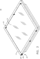
- FIG. 2 illustrates that the touch screen surface of the display screen 24 can be located within a frame assembly 22.
- a lower housing 26 and upper housing 27 can be included in the frame assembly 22.
- a mounting flange 25 can be provided or integrally formed within the lower housing 26.
- a fastener assembly 30 can be provided to secure the frame assembly 22 to a portion of the aircraft cockpit 10. While a single fastener assembly 30 is illustrated in detail, it will be appreciated that a set of fastener assemblies 30 can be included in the avionics display assembly 20. As such a set of phantom schematic fastener assemblies 30 have been illustrated at various locations about the frame assembly 22. More specifically, fastener assemblies 30 have been included at the corners and several of the midpoints of edges of the frame assembly 22. It will be understood that any suitable number of fastener assemblies can be included at any suitable locations.
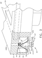
- a cavity 28 can be defined within the lower housing 27, and the fastener assembly 30 can be housed within the cavity 28 as shown in FIG 3 .
- a spring locking quarter turn fastener 32 having a head 34 and a thread 36 can be included in the fastener assembly 30, where the head 34 can be positioned on a non-display side 20A of the display assembly 20, and the thread 36 can extend to a display side 20B of the display assembly 20 as shown.
- a standard 4-40UNC thread is contemplated for the thread 36, and it will be understood that any suitable thread may be used.
- the spring locking quarter turn fastener 32 can form a rail engagement fastener configured to mount to a cockpit rail by way of a fastener spring 37, a portion of which is illustrated in FIG. 3 .
- the quarter turn fastener 32 is illustrated herein as a quarter turn line fastener that can move downward to engage the fastener spring 37, where a quarter-turn rotation of the head 34 can lock the fastener spring 37 into place and secure the frame assembly 22 in the cockpit 10. It will be understood that other types or styles of fasteners are contemplated for use in the fastener assembly 30.
- a spring assembly 40 movably coupled about at least a portion of the thread 36, can also be included in the fastener assembly 30.
- the spring assembly 40 can include a set of stacked leaf springs, illustrated as a first leaf spring 41 and second leaf spring 42.
- the first leaf spring 41' and second leaf spring 42 can be made of 301 stainless steel.
- the leaf springs 41 and 42 can be sized to exert the same or differing amounts of spring force under a given amount of compression as desired. It can be appreciated that the spring forces exerted by each leaf spring 41, 42 are combined when the leaf springs 41, 42 are in the stacked arrangement.
- a bushing 38 can be included in the fastener assembly 30.
- the bushing 38 can be located about at least a portion of the thread 36 and can be configured to space the spring assembly 40 from the mounting flange 25.
- the bushing can be formed from stainless steel in a non-limiting example, and can also be integrally formed with the flange 25 or provided as a separately-attachable piece as shown.
- Mounting hardware 44 can be included within the fastener assembly 30 and used to secure the spring assembly 40 to the thread 36.
- the mounting hardware 44 is illustrated, in a non-limiting example, as a stainless steel threaded nut 45 and washer 46. It will be understood that any suitable mounting hardware 44 can be utilized.
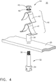
- the fastener assembly 30 can be seen in greater detail in the exploded view of FIG. 4 .
- the quarter turn fastener 32 can be positioned below the mounting flange 25 such that the thread 36 can extend through the mounting flange 25 when assembled.
- the bushing 38 can be positioned above the mounting flange 25.
- the first leaf spring 41 and second leaf spring 42 can be positioned above the bushing 38 in a stacked configuration as shown.
- the mounting hardware 44 can be positioned at the distal end of the thread 36 to hold the spring assembly 40 onto the thread 36.
- the bushing 38, first leaf spring 41, and second leaf spring 42 can be slidably received on the thread 36, and the mounting hardware 44 (such as the threaded nut) can be tightened about the thread 36 to secure the components to form the assembled fastener assembly 30.
- the spring assembly 40 is illustrated in a first position, where the leaf springs 41, 42 are at rest and the quarter-turn fastener 32 is positioned abutting the mounting flange 25.
- the spring assembly 40 can compress in a vertical direction when assembled and tightened by the mounting hardware 44, and FIG. 6 illustrates the spring assembly 40 in a second, flexed or compressed position.
- the quarter turn fastener 32 is displaced in a vertical direction shown by an arrow 48 during compression of the spring assembly 40 and become spaced apart from the mounting flange 25.
- the spring assembly 40 can be configured to allow the quarter turn fastener 32 to be displaced vertically by 0.16 cm compared with a non-flexed position of the spring assembly 40. It can be appreciated that the vertical displacement of the quarter turn fastener 32 can provide for engagement with the fastener spring 37 ( FIG.
- the spring assembly 40 can also provide a retention force sufficient to ensure the proper retention force required by aircraft manufactures to secure cockpit electronics, and in one non-limiting example the spring assembly 40 can be configured to provide a retention force of at least 65 N when assembled and secured with the mounting hardware 44.
- the quarter turn fastener 32 can have a fastener width 33 and the mounting hardware 44 can have a hardware width 50 as shown. It should be understood that the fastener width 33 and hardware width 50 can describe the diameter or the largest dimension of the quarter turn fastener 32 and mounting hardware 44, respectively. It is contemplated that the fastener width 33 can be 0.75 cm or smaller, and a 0.635 cm (quarter-inch) nut is contemplated for use with the mounting hardware 44.
- an overall width 52 of the fastener assembly 30 can be the same size as the fastener width 33, such as 0.75cm or smaller in a non-limiting example.
- the hardware width 50 such as that of the quarter-inch (0.635cm) nut, can be smaller than the overall width 52 of the fastener assembly 30.
- the overall width 52 can be the same size as a width of the leaf springs 41, 42 as well as a width of the bushing 38.
- a width of the bushing 38 can be the same size or smaller than the overall width 52 such that the bushing 38 can fit fully within the leaf springs 41, 42.
- Quarter turn fasteners traditionally contain internal coil springs, where the force exerted by the coil springs is used to secure an electronics display to a mounting piece.
- Traditionally-used quarter turn fasteners include coil springs within their interior.
- a coil spring of sufficient strength, to securely mount the electronics display, generally has a standard diameter of 0.34 inches (0.87 cm).
- aspects of the avionics display assembly described in the present disclosure can provide for a variety of benefits.
- One benefit is at least a 25% reduction in width of the fastener assembly 30, which can increase the available space for touch screen displays. It can be further appreciated that in limited-space applications such as airplane cockpits, increasing the size or usable area of display or touch screens can improve the quality or delivery of information as well as optimize touch-screen applications such as keyboards.
- An additional benefit can be found in the use of the stacked leaf springs which can provide for an increase in available spring force, compared with springs found in traditional quarter turn fasteners, without increasing the overall width of the fastener assembly.
- fastener assembly 30 as described herein can be used in current existing aircraft cockpit electronics and also utilize pre-existing aircraft rails or wires to mount the display assembly 20 to the cockpit 10.
Landscapes
- Engineering & Computer Science (AREA)
- Mechanical Engineering (AREA)
- General Engineering & Computer Science (AREA)
- Physics & Mathematics (AREA)
- Chemical & Material Sciences (AREA)
- Combustion & Propulsion (AREA)
- Transportation (AREA)
- Nonlinear Science (AREA)
- Aviation & Aerospace Engineering (AREA)
- Optics & Photonics (AREA)
- General Physics & Mathematics (AREA)
- Crystallography & Structural Chemistry (AREA)
- Mathematical Physics (AREA)
- Connection Of Plates (AREA)
- Devices For Indicating Variable Information By Combining Individual Elements (AREA)
Abstract
Description
- Contemporary aircraft can include electronic devices including displays for displaying graphical, textual, or decimal information to a user, pilot, or co-pilot. Such information can be provided or presented to a user to inform the user of the status of the aircraft or a system thereof.
- Displays can be mounted within the aircraft. As aircraft displays utilize increased space for functions such as touch-sensitive screens or larger readout sizes, strategic use of fastener size and placement can be beneficial to optimize displayed information.
- In one aspect, a fastener assembly for cockpit electronics includes a quarter turn spring locking fastener having a head on a non-display side of the assembly and a thread extending to a display side of the assembly, a spring assembly including at least two leaf springs in a stacked configuration moveably coupled about at least a portion of the thread, and mounting hardware configured to secure the spring assembly to the thread.
- In another aspect, an avionics display assembly includes a frame assembly including a mounting flange, a touch screen display operably coupled to the frame assembly, at least one fastener assembly including a quarter turn spring locking fastener having a head on a non-display side of the assembly and a thread extending to a display side of the assembly, a spring assembly including at least two leaf springs in a stacked configuration moveably coupled about at least a portion of the thread, and mounting hardware configured to secure the spring assembly to the thread.
- In yet another aspect, an avionics display assembly includes a frame assembly including a mounting flange having at least one opening and defining a display side and a non-display side, a display screen operably coupled to the frame assembly, a set of fastener assemblies including a quarter turn spring locking fastener having a head located on the non-display side and a threaded portion extending through the at least one opening to the display side, a spring assembly including at least two leaf springs in a stacked configuration moveably coupled about at least a portion of the thread on the display side, a bushing located between the mounting flange and the spring assembly, and mounting hardware configured to secure the spring assembly to the thread.
- In the drawings:
-
FIG. 1 is a perspective view of a portion of a cockpit including a display assembly. -
FIG. 2 is a perspective view of the display assembly ofFIG. 1 including a fastener assembly within a partially cutaway frame assembly. -
FIG. 3 is a perspective view of the fastener assembly ofFIG. 2 within a partially cutaway frame assembly. -
FIG. 4 is an exploded perspective view of the fastener assembly ofFIG. 2 . -
FIG. 5 is a side view of the fastener assembly ofFIG. 2 in a first position. -
FIG. 6 is a side view of the fastener assembly ofFIG. 2 in a second position. -
FIG. 7 is a top view of the fastener assembly ofFIG. 2 positioned within the display assembly ofFIG. 2 . - The described embodiments of the present disclosure are directed to a fastener assembly. For purposes of illustration, the present disclosure will be described with respect to an aircraft cockpit electronics fastener assembly. It will be understood that the disclosure is not so limited and that the fastener assembly can be used anywhere within the aircraft, or in other electronics applications, or in other mobile or non-mobile applications as desired.
- While "a set of' various elements will be described, it will be understood that "a set" can include any number of the respective elements, including only one element. As used herein, the terms "axial" or "axially" refer to a dimension along a longitudinal axis of an electric machine or along a longitudinal axis of a component disposed within the engine. As used herein, the terms "radial" or "radially" refer to a dimension extending between a center longitudinal axis of the engine, an outer rotational circumference, or a circular or annular component disposed within the engine. The use of the terms "proximal" or "proximally," either by themselves or in conjunction with the terms "radial" or "radially," refers to moving in a direction toward the center longitudinal axis, or a component being relatively closer to the center longitudinal axis as compared to another component.
- All directional references (e.g., radial, axial, proximal, distal, upper, lower, upward, downward, left, right, lateral, front, back, top, bottom, above, below, vertical, horizontal, clockwise, counterclockwise, upstream, downstream, forward, aft, etc.) are only used for identification purposes to aid the reader's understanding of the present disclosure, and do not create limitations, particularly as to the position, orientation, or use of the disclosure. Connection references (e.g., attached, coupled, connected, and joined) are to be construed broadly and can include intermediate members between a collection of elements and relative movement between elements unless otherwise indicated. As such, connection references do not necessarily infer that two elements are directly connected and in fixed relation to one another. The exemplary drawings are for purposes of illustration only and the dimensions, positions, order and relative sizes reflected in the drawings attached hereto can vary.
-
FIG. 1 illustrates a non-limiting example of a portion of anaircraft cockpit 10. While a commercial aircraft has been illustrated, it is contemplated that aspects of the disclosure can be used in any type of legacy aircraft, for example, without limitation, fixed-wing, rotating-wing, rocket, personal aircraft, and military aircraft. A first user (e.g., a pilot) can be present in aseat 12 at the left side of thecockpit 10 and another user (e.g., a co-pilot) can be present at the right side of thecockpit 10 in aseat 14. Aflight deck 16 can includevarious instruments 18,various displays 19, and a set ofavionics display assemblies 20. In one non-limiting aspect of the disclosure, adisplay assembly 20 can include a multifunction flight display with adisplay screen 24 that can be located in front of the pilot or co-pilot and can provide the flight crew with information to aid in flying the aircraft. - The
display screen 24 can include either primary flight displays or multi-function displays and can display a wide range of aircraft, flight, navigation, and other information used in the operation and control of the aircraft. Non-limiting aspects of thedisplay screen 24 can include displaying color graphics or text to a user, pilot, or co-pilot. The set ofdisplay assemblies 20 can be laid out in any manner, and need not be coplanar or the same size. - A touch screen display or touch screen surface can be included in the
display screens 24 and can be used by one or more flight crewmembers, including the pilot and co-pilot, to interact with the systems of the aircraft. -
FIG. 2 illustrates that the touch screen surface of thedisplay screen 24 can be located within aframe assembly 22. Alower housing 26 andupper housing 27 can be included in theframe assembly 22. Amounting flange 25 can be provided or integrally formed within thelower housing 26. Afastener assembly 30 can be provided to secure theframe assembly 22 to a portion of theaircraft cockpit 10. While asingle fastener assembly 30 is illustrated in detail, it will be appreciated that a set offastener assemblies 30 can be included in theavionics display assembly 20. As such a set of phantomschematic fastener assemblies 30 have been illustrated at various locations about theframe assembly 22. More specifically,fastener assemblies 30 have been included at the corners and several of the midpoints of edges of theframe assembly 22. It will be understood that any suitable number of fastener assemblies can be included at any suitable locations. - A
cavity 28 can be defined within thelower housing 27, and thefastener assembly 30 can be housed within thecavity 28 as shown inFIG 3 . A spring lockingquarter turn fastener 32 having ahead 34 and athread 36 can be included in thefastener assembly 30, where thehead 34 can be positioned on anon-display side 20A of thedisplay assembly 20, and thethread 36 can extend to adisplay side 20B of thedisplay assembly 20 as shown. A standard 4-40UNC thread is contemplated for thethread 36, and it will be understood that any suitable thread may be used. - The spring locking
quarter turn fastener 32 can form a rail engagement fastener configured to mount to a cockpit rail by way of afastener spring 37, a portion of which is illustrated inFIG. 3 . Thequarter turn fastener 32 is illustrated herein as a quarter turn line fastener that can move downward to engage thefastener spring 37, where a quarter-turn rotation of thehead 34 can lock thefastener spring 37 into place and secure theframe assembly 22 in thecockpit 10. It will be understood that other types or styles of fasteners are contemplated for use in thefastener assembly 30. - A
spring assembly 40, movably coupled about at least a portion of thethread 36, can also be included in thefastener assembly 30. Thespring assembly 40 can include a set of stacked leaf springs, illustrated as afirst leaf spring 41 andsecond leaf spring 42. By way of non-limiting example, the first leaf spring 41' andsecond leaf spring 42 can be made of 301 stainless steel. Theleaf springs leaf spring leaf springs - A
bushing 38 can be included in thefastener assembly 30. Thebushing 38 can be located about at least a portion of thethread 36 and can be configured to space thespring assembly 40 from themounting flange 25. The bushing can be formed from stainless steel in a non-limiting example, and can also be integrally formed with theflange 25 or provided as a separately-attachable piece as shown. -
Mounting hardware 44 can be included within thefastener assembly 30 and used to secure thespring assembly 40 to thethread 36. In the illustrated example, themounting hardware 44 is illustrated, in a non-limiting example, as a stainless steel threadednut 45 andwasher 46. It will be understood that anysuitable mounting hardware 44 can be utilized. - The
fastener assembly 30 can be seen in greater detail in the exploded view ofFIG. 4 . Thequarter turn fastener 32 can be positioned below the mountingflange 25 such that thethread 36 can extend through the mountingflange 25 when assembled. Thebushing 38 can be positioned above the mountingflange 25. Thefirst leaf spring 41 andsecond leaf spring 42 can be positioned above thebushing 38 in a stacked configuration as shown. The mountinghardware 44 can be positioned at the distal end of thethread 36 to hold thespring assembly 40 onto thethread 36. - When assembled as shown in
FIG. 5 , thebushing 38,first leaf spring 41, andsecond leaf spring 42 can be slidably received on thethread 36, and the mounting hardware 44 (such as the threaded nut) can be tightened about thethread 36 to secure the components to form the assembledfastener assembly 30. Thespring assembly 40 is illustrated in a first position, where theleaf springs turn fastener 32 is positioned abutting the mountingflange 25. - The
spring assembly 40 can compress in a vertical direction when assembled and tightened by the mountinghardware 44, andFIG. 6 illustrates thespring assembly 40 in a second, flexed or compressed position. When thespring assembly 40 has been compressed, thequarter turn fastener 32 is displaced in a vertical direction shown by anarrow 48 during compression of thespring assembly 40 and become spaced apart from the mountingflange 25. In a non-limiting example thespring assembly 40 can be configured to allow thequarter turn fastener 32 to be displaced vertically by 0.16 cm compared with a non-flexed position of thespring assembly 40. It can be appreciated that the vertical displacement of thequarter turn fastener 32 can provide for engagement with the fastener spring 37 (FIG. 3 ) to mount theframe assembly 22 to the cockpit 10 (FIG 1 ). Thespring assembly 40 can also provide a retention force sufficient to ensure the proper retention force required by aircraft manufactures to secure cockpit electronics, and in one non-limiting example thespring assembly 40 can be configured to provide a retention force of at least 65 N when assembled and secured with the mountinghardware 44. - The
quarter turn fastener 32 can have afastener width 33 and the mountinghardware 44 can have ahardware width 50 as shown. It should be understood that thefastener width 33 andhardware width 50 can describe the diameter or the largest dimension of thequarter turn fastener 32 and mountinghardware 44, respectively. It is contemplated that thefastener width 33 can be 0.75 cm or smaller, and a 0.635 cm (quarter-inch) nut is contemplated for use with the mountinghardware 44. - Turning to
FIG. 7 , thefastener assembly 30 is illustrated while mounted to a portion of theframe assembly 22. It is contemplated that anoverall width 52 of thefastener assembly 30 can be the same size as thefastener width 33, such as 0.75cm or smaller in a non-limiting example. Thehardware width 50, such as that of the quarter-inch (0.635cm) nut, can be smaller than theoverall width 52 of thefastener assembly 30. In one non-limiting example theoverall width 52 can be the same size as a width of theleaf springs bushing 38. In another non-limiting example a width of thebushing 38 can be the same size or smaller than theoverall width 52 such that thebushing 38 can fit fully within theleaf springs - Quarter turn fasteners traditionally contain internal coil springs, where the force exerted by the coil springs is used to secure an electronics display to a mounting piece. Traditionally-used quarter turn fasteners include coil springs within their interior. A coil spring of sufficient strength, to securely mount the electronics display, generally has a standard diameter of 0.34 inches (0.87 cm).
- It can be appreciated that aspects of the avionics display assembly described in the present disclosure can provide for a variety of benefits. One benefit is at least a 25% reduction in width of the
fastener assembly 30, which can increase the available space for touch screen displays. It can be further appreciated that in limited-space applications such as airplane cockpits, increasing the size or usable area of display or touch screens can improve the quality or delivery of information as well as optimize touch-screen applications such as keyboards. An additional benefit can be found in the use of the stacked leaf springs which can provide for an increase in available spring force, compared with springs found in traditional quarter turn fasteners, without increasing the overall width of the fastener assembly. While other traditional mounting systems such as cams or levers can be used to mount display screens, the complexity involved in arranging such systems within aircraft cockpits can increase cost or failure rates. It can be appreciated that thefastener assembly 30 as described herein can be used in current existing aircraft cockpit electronics and also utilize pre-existing aircraft rails or wires to mount thedisplay assembly 20 to thecockpit 10. - To the extent not already described, the different features and structures of the various embodiments can be used in combination, or in substitution with each other as desired. That one feature is not illustrated in all of the embodiments is not meant to be construed that it cannot be so illustrated, but is done for brevity of description. Thus, the various features of the different embodiments can be mixed and matched as desired to form new embodiments, whether or not the new embodiments are expressly described. All combinations or permutations of features described herein are covered by this disclosure.
- This written description uses examples to disclose the invention, including the best mode, and also to enable any person skilled in the art to practice the invention, including making and using any devices or systems and performing any incorporated methods. The patentable scope of the invention is defined by the claims, and may include other examples that occur to those skilled in the art. Such other examples are intended to be within the scope of the claims if they have structural elements that do not differ from the literal language of the claims, or if they include equivalent structural elements with insubstantial differences from the literal languages of the claims.
- Various aspects and embodiments of the present invention are defined by the following numbered clauses:
- 1. A fastener assembly for cockpit electronics, comprising:
- a spring locking quarter turn fastener having a head on a non-display side of the assembly and a thread extending to a display side of the assembly;
- a spring assembly including at least two leaf springs in a stacked configuration moveably coupled about at least a portion of the thread; and
- mounting hardware configured to secure the spring assembly to the thread.
- 2. The fastener assembly of
clause 1, wherein the spring assembly is configured to provide a retention force of at least 65 N. - 3. The fastener assembly of any preceding clause, wherein the quarter turn fastener has a diameter of 0.75 cm.
- 4. The fastener assembly of any preceding clause, wherein flexion of the spring assembly is configured to allow a vertical displacement of 0.16 cm of the quarter turn fastener.
- 5. The fastener assembly of any preceding clause, wherein the quarter turn fastener comprises a rail engagement fastener configured to mount to a cockpit rail.
- 6. The fastener assembly of any preceding clause, wherein the rail engagement fastener is a quarter turn line fastener.
- 7. The fastener assembly of any preceding clause, wherein the mounting hardware includes a 0.635 cm nut.
- 8. The fastener assembly of any preceding clause, further comprising a bushing located about at least a portion of the thread and configured to space the spring assembly from a mounting flange of the cockpit electronics.
- 9. The fastener assembly of any preceding clause, wherein the quarter turn fastener has a width less than or equal to 0.75 cm.
- 10. An avionics display assembly, comprising:
- a frame assembly including a mounting flange;
- a touch screen display operably coupled to the frame assembly; and
- at least one fastener assembly, comprising:
- a spring locking quarter turn fastener having a head on a non-display side of the assembly and a thread extending to a display side of the assembly;
- a spring assembly including at least two leaf springs in a stacked configuration moveably coupled about at least a portion of the thread; and
- mounting hardware configured to secure the spring assembly to the thread.
- 11. The avionics display assembly of any preceding clause, wherein the spring assembly is configured to provide a retention force of at least 65 N.
- 12. The avionics display assembly of any preceding clause, wherein the quarter turn fastener comprises a rail engagement fastener configured to mount to a cockpit rail and having a diameter equal to or less than 0.75 cm.
- 13. The avionics display assembly of any preceding clause, further comprising a bushing located about at least a portion of the thread and configured to space the spring assembly from a mounting flange of the cockpit electronics.
- 14. The avionics display assembly of any preceding clause, wherein the quarter turn fastener has a width less than or equal to 0.75 cm.
- 15. The avionics display assembly of any preceding clause, wherein the frame assembly comprises an upper housing and a lower housing.
- 16. The avionics display assembly of any preceding clause, wherein the lower housing includes a cavity and the spring assembly is housed within the cavity.
- 17. The avionics display assembly of any preceding clause, wherein at least one fastener assembly includes multiple fastener assemblies located at least at corners of the mounting flange.
- 18. An avionics display assembly, comprising:
- a frame assembly including a mounting flange having at least one opening and defining a display side and a non-display side;
- a display screen operably coupled to the frame assembly; and
- a set of fastener assemblies, comprising:
- a spring locking quarter turn fastener having a head located on the non-display side and a threaded portion extending through the at least one opening to the display side;
- a spring assembly including at least two leaf springs in a stacked configuration moveably coupled about at least a portion of the thread on the display side;
- a bushing located between the mounting flange and the spring assembly; and
- mounting hardware configured to secure the spring assembly to the thread.
- 19. The avionics display assembly of any preceding clause, wherein the quarter turn fastener has a width less than or equal to 0.75 cm and the spring assembly is configured to provide a retention force of at least 65 N.
- 20. The avionics display assembly of any preceding clause, wherein the display screen is a touchscreen.
Claims (13)
- A fastener assembly (30) for cockpit electronics, comprising:a spring locking quarter turn fastener (32) having a head (34) on a non-display side (20A) of the assembly (30) and a thread (36) extending to a display side (20B) of the assembly (30);a spring assembly (40) including at least two leaf springs (41, 42) in a stacked configuration moveably coupled about at least a portion of the thread (36); andmounting hardware (44) configured to secure the spring assembly (40) to the thread (36).
- The fastener assembly (30) of claim 1, wherein the spring assembly (40) is configured to provide a retention force of at least 65 N.
- The fastener assembly (30) of either of claim 1 or 2, wherein the quarter turn fastener (32) has a diameter (33) of 0.75 cm.
- The fastener assembly (30) of any preceding claim, wherein flexion of the spring assembly (40) is configured to allow a vertical displacement (48) of 0.16 cm of the quarter turn fastener (32).
- The fastener assembly (30) of any preceding claim, wherein the quarter turn fastener (32) comprises a rail engagement fastener (32) configured to mount to a cockpit rail (37).
- The fastener assembly (30) of claim 5, wherein the rail engagement fastener (32) is a quarter turn line fastener (32).
- The fastener assembly (30) of any preceding claim, wherein the mounting hardware includes a 0.635 cm nut (45).
- The fastener assembly (30) of any preceding claim, further comprising a bushing (38) located about at least a portion of the thread (36) and configured to space the spring assembly (40) from a mounting flange (25) of the cockpit electronics.
- The fastener assembly (30) of any preceding claim, wherein the quarter turn fastener (32) has a width (33) less than or equal to 0.75 cm.
- An avionics display assembly, comprising:a frame assembly including a mounting flange;a touch screen display operably coupled to the frame assembly; andat least one fastener assembly in accordance with any of the preceding claims.
- The avionics display assembly of claim 10, wherein the frame assembly comprises an upper housing and a lower housing.
- The avionics display assembly of claim 11, wherein the lower housing includes a cavity and the spring assembly is housed within the cavity.
- The avionics display assembly of any of claims 10 to 12, wherein at least one fastener assembly includes multiple fastener assemblies located at least at corners of the mounting flange.
Applications Claiming Priority (1)
| Application Number | Priority Date | Filing Date | Title |
|---|---|---|---|
| US15/611,120 US10239466B2 (en) | 2017-06-01 | 2017-06-01 | Avionics display fastener assembly |
Publications (2)
| Publication Number | Publication Date |
|---|---|
| EP3409958A1 true EP3409958A1 (en) | 2018-12-05 |
| EP3409958B1 EP3409958B1 (en) | 2024-10-16 |
Family
ID=62712711
Family Applications (1)
| Application Number | Title | Priority Date | Filing Date |
|---|---|---|---|
| EP18175562.0A Active EP3409958B1 (en) | 2017-06-01 | 2018-06-01 | Avionics display fastener assembly |
Country Status (4)
| Country | Link |
|---|---|
| US (1) | US10239466B2 (en) |
| EP (1) | EP3409958B1 (en) |
| BR (1) | BR102018011023A2 (en) |
| CA (1) | CA3005186A1 (en) |
Families Citing this family (7)
| Publication number | Priority date | Publication date | Assignee | Title |
|---|---|---|---|---|
| US10392129B1 (en) * | 2018-04-10 | 2019-08-27 | Rockwell Collins, Inc. | Integrated micro-LED luminous aircraft panel |
| US20190323541A1 (en) | 2018-04-21 | 2019-10-24 | Maxim Defense Industries, LLC | Universal interface system, fastener apparatus and accessory rail system |
| US10622761B1 (en) * | 2018-08-30 | 2020-04-14 | Facebook, Inc. | Moveable floating connector |
| US11029548B2 (en) * | 2019-09-13 | 2021-06-08 | Panasonic Avionics Corporation | In-flight entertainment systems and monitor assemblies for in-flight entertainment systems |
| USD1004033S1 (en) | 2020-01-20 | 2023-11-07 | Sagi Faifer | Handguard for a gun |
| DE102020109188A1 (en) * | 2020-04-02 | 2021-10-07 | Airbus Operations Gmbh | Fastening system, monument and method for attaching an item of equipment to a monument |
| US20240010132A1 (en) * | 2022-07-11 | 2024-01-11 | South East Manufacturing, Inc. | Attachment assemblies, attachments, attachment hardware for securing accessories to window frames of vehicles, and related methods |
Citations (5)
| Publication number | Priority date | Publication date | Assignee | Title |
|---|---|---|---|---|
| JPS52115191U (en) * | 1976-02-27 | 1977-09-01 | ||
| JPS5849009U (en) * | 1981-09-29 | 1983-04-02 | 株式会社東芝 | Fixation device |
| US20070266514A1 (en) * | 2006-05-17 | 2007-11-22 | Umbrell Richard T | Quick release connector for dual-sided buffing pad |
| WO2010039279A1 (en) * | 2008-09-30 | 2010-04-08 | Raytheon Company | Systems and methods for blind-mate connector alignment |
| US20160264061A1 (en) * | 2015-03-13 | 2016-09-15 | Thales | Mechanical fixing system for aeronautical display device |
Family Cites Families (10)
| Publication number | Priority date | Publication date | Assignee | Title |
|---|---|---|---|---|
| JPS55112437A (en) * | 1979-02-22 | 1980-08-30 | Nhk Spring Co Ltd | Laminated leaf spring device |
| US6343863B1 (en) | 2000-03-20 | 2002-02-05 | Rockwell Collins, Inc. | Aircraft display mounting system |
| US6592387B2 (en) | 2000-12-22 | 2003-07-15 | Honeywell International Inc. | Spring-loaded connector setup for blind mating and method for using the same |
| US6549424B1 (en) | 2002-02-28 | 2003-04-15 | Garmin Ltd. | Electronic equipment module mounting apparatus and method |
| DE20205139U1 (en) * | 2002-04-02 | 2003-01-02 | Hasenstab, Werner, Dipl.-Ing., 63814 Mainaschaff | Disk spring comprises a washer which has one or more curves and bearing areas |
| US7393168B2 (en) * | 2004-07-30 | 2008-07-01 | Grace-Comp Systems, Ltd. | Retractable fastener device and method for facilitating the fastening of multiple objects |
| US8701953B2 (en) | 2009-10-09 | 2014-04-22 | Raytheon Company | Electronic flight bag mounting system |
| US9317146B1 (en) | 2012-08-23 | 2016-04-19 | Rockwell Collins, Inc. | Haptic touch feedback displays having double bezel design |
| FR3019115B1 (en) * | 2014-03-27 | 2016-04-15 | A Raymond Et Cie | DEVICE FOR ATTACHING TO A RAIL |
| JP6503717B2 (en) * | 2014-12-09 | 2019-04-24 | 日本精機株式会社 | Head-up display device |
-
2017
- 2017-06-01 US US15/611,120 patent/US10239466B2/en active Active
-
2018
- 2018-05-17 CA CA3005186A patent/CA3005186A1/en not_active Abandoned
- 2018-05-30 BR BR102018011023-3A patent/BR102018011023A2/en not_active IP Right Cessation
- 2018-06-01 EP EP18175562.0A patent/EP3409958B1/en active Active
Patent Citations (5)
| Publication number | Priority date | Publication date | Assignee | Title |
|---|---|---|---|---|
| JPS52115191U (en) * | 1976-02-27 | 1977-09-01 | ||
| JPS5849009U (en) * | 1981-09-29 | 1983-04-02 | 株式会社東芝 | Fixation device |
| US20070266514A1 (en) * | 2006-05-17 | 2007-11-22 | Umbrell Richard T | Quick release connector for dual-sided buffing pad |
| WO2010039279A1 (en) * | 2008-09-30 | 2010-04-08 | Raytheon Company | Systems and methods for blind-mate connector alignment |
| US20160264061A1 (en) * | 2015-03-13 | 2016-09-15 | Thales | Mechanical fixing system for aeronautical display device |
Also Published As
| Publication number | Publication date |
|---|---|
| US10239466B2 (en) | 2019-03-26 |
| EP3409958B1 (en) | 2024-10-16 |
| BR102018011023A2 (en) | 2019-04-16 |
| US20180345873A1 (en) | 2018-12-06 |
| CA3005186A1 (en) | 2018-12-01 |
Similar Documents
| Publication | Publication Date | Title |
|---|---|---|
| US10239466B2 (en) | Avionics display fastener assembly | |
| EP2116811B1 (en) | Flight guidance and navigation display for a helicopter | |
| EP3280643B1 (en) | Privacy divider with video monitor function for vehicle passenger seating unit | |
| EP1899777B1 (en) | Standby display aircraft management system | |
| US20120256768A1 (en) | System and method of using a multi-view display | |
| US20120075120A1 (en) | Stepped instrument panel for aircraft | |
| US6343863B1 (en) | Aircraft display mounting system | |
| US12089758B2 (en) | Cupholder assembly | |
| US8994561B2 (en) | Modular display system for helicopters | |
| EP3873803B1 (en) | Extended display integration for passenger seats | |
| US9505487B2 (en) | Control panel for use in controlling a large area display | |
| US20200183491A1 (en) | Aircraft cockpit and method of displaying in an aircraft cockpit | |
| US8836543B2 (en) | Flight deck having a dual-view display and a method for operating same | |
| EP3862271B1 (en) | Combined divan aircraft seat for aircraft passenger compartment suites | |
| US20120320508A1 (en) | Display apparatus for a passenger cabin of an aircraft or spacecraft | |
| EP3960038B1 (en) | Attachment assembly for a dress cover and a cushion of an aircraft seat | |
| US20150353204A1 (en) | Display system for use in a flight deck of an aircraft | |
| CN108051918A (en) | A kind of telecontrol equipment of head-up display compound glass | |
| CN109927874A (en) | The sealed bottom of aircraft front part, the front part and aircraft of aircraft | |
| US20130037659A1 (en) | Control Quadrant | |
| CN111703579A (en) | Adjustable brewing head linkage device | |
| CN106697310A (en) | Quick-disassembly structure for aviation displayer | |
| US12409946B1 (en) | Instrument panel systems and methods for aircraft cockpits | |
| US8449009B1 (en) | Adapter for attachment of a display unit to a console of a vehicle | |
| Sherbert | Cockpit Advances in Boeing Vertol Company's Model 360 Helicopter |
Legal Events
| Date | Code | Title | Description |
|---|---|---|---|
| PUAI | Public reference made under article 153(3) epc to a published international application that has entered the european phase |
Free format text: ORIGINAL CODE: 0009012 |
|
| STAA | Information on the status of an ep patent application or granted ep patent |
Free format text: STATUS: THE APPLICATION HAS BEEN PUBLISHED |
|
| AK | Designated contracting states |
Kind code of ref document: A1 Designated state(s): AL AT BE BG CH CY CZ DE DK EE ES FI FR GB GR HR HU IE IS IT LI LT LU LV MC MK MT NL NO PL PT RO RS SE SI SK SM TR |
|
| AX | Request for extension of the european patent |
Extension state: BA ME |
|
| STAA | Information on the status of an ep patent application or granted ep patent |
Free format text: STATUS: REQUEST FOR EXAMINATION WAS MADE |
|
| 17P | Request for examination filed |
Effective date: 20190605 |
|
| RBV | Designated contracting states (corrected) |
Designated state(s): AL AT BE BG CH CY CZ DE DK EE ES FI FR GB GR HR HU IE IS IT LI LT LU LV MC MK MT NL NO PL PT RO RS SE SI SK SM TR |
|
| STAA | Information on the status of an ep patent application or granted ep patent |
Free format text: STATUS: EXAMINATION IS IN PROGRESS |
|
| 17Q | First examination report despatched |
Effective date: 20210810 |
|
| GRAP | Despatch of communication of intention to grant a patent |
Free format text: ORIGINAL CODE: EPIDOSNIGR1 |
|
| STAA | Information on the status of an ep patent application or granted ep patent |
Free format text: STATUS: GRANT OF PATENT IS INTENDED |
|
| INTG | Intention to grant announced |
Effective date: 20240513 |
|
| RIN1 | Information on inventor provided before grant (corrected) |
Inventor name: CAMPBELL, MARK WOODWORTH |
|
| GRAS | Grant fee paid |
Free format text: ORIGINAL CODE: EPIDOSNIGR3 |
|
| GRAA | (expected) grant |
Free format text: ORIGINAL CODE: 0009210 |
|
| STAA | Information on the status of an ep patent application or granted ep patent |
Free format text: STATUS: THE PATENT HAS BEEN GRANTED |
|
| AK | Designated contracting states |
Kind code of ref document: B1 Designated state(s): AL AT BE BG CH CY CZ DE DK EE ES FI FR GB GR HR HU IE IS IT LI LT LU LV MC MK MT NL NO PL PT RO RS SE SI SK SM TR |
|
| REG | Reference to a national code |
Ref country code: GB Ref legal event code: FG4D |
|
| REG | Reference to a national code |
Ref country code: CH Ref legal event code: PK Free format text: BERICHTIGUNGEN Ref country code: CH Ref legal event code: EP Ref country code: DE Ref legal event code: R096 Ref document number: 602018075439 Country of ref document: DE |
|
| REG | Reference to a national code |
Ref country code: IE Ref legal event code: FG4D |
|
| P01 | Opt-out of the competence of the unified patent court (upc) registered |
Free format text: CASE NUMBER: APP_55946/2024 Effective date: 20241011 |
|
| RIN2 | Information on inventor provided after grant (corrected) |
Inventor name: CARRILLO, DAVID HOWARD Inventor name: CAMPBELL, MARK WOODWORTH |
|
| REG | Reference to a national code |
Ref country code: LT Ref legal event code: MG9D |
|
| REG | Reference to a national code |
Ref country code: NL Ref legal event code: MP Effective date: 20241016 |
|
| REG | Reference to a national code |
Ref country code: AT Ref legal event code: MK05 Ref document number: 1733124 Country of ref document: AT Kind code of ref document: T Effective date: 20241016 |
|
| PG25 | Lapsed in a contracting state [announced via postgrant information from national office to epo] |
Ref country code: NL Free format text: LAPSE BECAUSE OF FAILURE TO SUBMIT A TRANSLATION OF THE DESCRIPTION OR TO PAY THE FEE WITHIN THE PRESCRIBED TIME-LIMIT Effective date: 20241016 |
|
| PG25 | Lapsed in a contracting state [announced via postgrant information from national office to epo] |
Ref country code: NL Free format text: LAPSE BECAUSE OF FAILURE TO SUBMIT A TRANSLATION OF THE DESCRIPTION OR TO PAY THE FEE WITHIN THE PRESCRIBED TIME-LIMIT Effective date: 20241016 |
|
| PG25 | Lapsed in a contracting state [announced via postgrant information from national office to epo] |
Ref country code: HR Free format text: LAPSE BECAUSE OF FAILURE TO SUBMIT A TRANSLATION OF THE DESCRIPTION OR TO PAY THE FEE WITHIN THE PRESCRIBED TIME-LIMIT Effective date: 20241016 Ref country code: IS Free format text: LAPSE BECAUSE OF FAILURE TO SUBMIT A TRANSLATION OF THE DESCRIPTION OR TO PAY THE FEE WITHIN THE PRESCRIBED TIME-LIMIT Effective date: 20250216 Ref country code: PT Free format text: LAPSE BECAUSE OF FAILURE TO SUBMIT A TRANSLATION OF THE DESCRIPTION OR TO PAY THE FEE WITHIN THE PRESCRIBED TIME-LIMIT Effective date: 20250217 |
|
| PG25 | Lapsed in a contracting state [announced via postgrant information from national office to epo] |
Ref country code: FI Free format text: LAPSE BECAUSE OF FAILURE TO SUBMIT A TRANSLATION OF THE DESCRIPTION OR TO PAY THE FEE WITHIN THE PRESCRIBED TIME-LIMIT Effective date: 20241016 |
|
| PG25 | Lapsed in a contracting state [announced via postgrant information from national office to epo] |
Ref country code: BG Free format text: LAPSE BECAUSE OF FAILURE TO SUBMIT A TRANSLATION OF THE DESCRIPTION OR TO PAY THE FEE WITHIN THE PRESCRIBED TIME-LIMIT Effective date: 20241016 |
|
| PG25 | Lapsed in a contracting state [announced via postgrant information from national office to epo] |
Ref country code: ES Free format text: LAPSE BECAUSE OF FAILURE TO SUBMIT A TRANSLATION OF THE DESCRIPTION OR TO PAY THE FEE WITHIN THE PRESCRIBED TIME-LIMIT Effective date: 20241016 |
|
| PG25 | Lapsed in a contracting state [announced via postgrant information from national office to epo] |
Ref country code: NO Free format text: LAPSE BECAUSE OF FAILURE TO SUBMIT A TRANSLATION OF THE DESCRIPTION OR TO PAY THE FEE WITHIN THE PRESCRIBED TIME-LIMIT Effective date: 20250116 |
|
| PG25 | Lapsed in a contracting state [announced via postgrant information from national office to epo] |
Ref country code: AT Free format text: LAPSE BECAUSE OF FAILURE TO SUBMIT A TRANSLATION OF THE DESCRIPTION OR TO PAY THE FEE WITHIN THE PRESCRIBED TIME-LIMIT Effective date: 20241016 Ref country code: LV Free format text: LAPSE BECAUSE OF FAILURE TO SUBMIT A TRANSLATION OF THE DESCRIPTION OR TO PAY THE FEE WITHIN THE PRESCRIBED TIME-LIMIT Effective date: 20241016 Ref country code: GR Free format text: LAPSE BECAUSE OF FAILURE TO SUBMIT A TRANSLATION OF THE DESCRIPTION OR TO PAY THE FEE WITHIN THE PRESCRIBED TIME-LIMIT Effective date: 20250117 |
|
| PG25 | Lapsed in a contracting state [announced via postgrant information from national office to epo] |
Ref country code: PL Free format text: LAPSE BECAUSE OF FAILURE TO SUBMIT A TRANSLATION OF THE DESCRIPTION OR TO PAY THE FEE WITHIN THE PRESCRIBED TIME-LIMIT Effective date: 20241016 |
|
| PG25 | Lapsed in a contracting state [announced via postgrant information from national office to epo] |
Ref country code: RS Free format text: LAPSE BECAUSE OF FAILURE TO SUBMIT A TRANSLATION OF THE DESCRIPTION OR TO PAY THE FEE WITHIN THE PRESCRIBED TIME-LIMIT Effective date: 20250116 |
|
| PG25 | Lapsed in a contracting state [announced via postgrant information from national office to epo] |
Ref country code: SM Free format text: LAPSE BECAUSE OF FAILURE TO SUBMIT A TRANSLATION OF THE DESCRIPTION OR TO PAY THE FEE WITHIN THE PRESCRIBED TIME-LIMIT Effective date: 20241016 |
|
| PGFP | Annual fee paid to national office [announced via postgrant information from national office to epo] |
Ref country code: DE Payment date: 20250520 Year of fee payment: 8 |
|
| PG25 | Lapsed in a contracting state [announced via postgrant information from national office to epo] |
Ref country code: DK Free format text: LAPSE BECAUSE OF FAILURE TO SUBMIT A TRANSLATION OF THE DESCRIPTION OR TO PAY THE FEE WITHIN THE PRESCRIBED TIME-LIMIT Effective date: 20241016 |
|
| PGFP | Annual fee paid to national office [announced via postgrant information from national office to epo] |
Ref country code: GB Payment date: 20250520 Year of fee payment: 8 |
|
| REG | Reference to a national code |
Ref country code: DE Ref legal event code: R097 Ref document number: 602018075439 Country of ref document: DE |
|
| PG25 | Lapsed in a contracting state [announced via postgrant information from national office to epo] |
Ref country code: EE Free format text: LAPSE BECAUSE OF FAILURE TO SUBMIT A TRANSLATION OF THE DESCRIPTION OR TO PAY THE FEE WITHIN THE PRESCRIBED TIME-LIMIT Effective date: 20241016 |
|
| PGFP | Annual fee paid to national office [announced via postgrant information from national office to epo] |
Ref country code: FR Payment date: 20250520 Year of fee payment: 8 |
|
| PG25 | Lapsed in a contracting state [announced via postgrant information from national office to epo] |
Ref country code: RO Free format text: LAPSE BECAUSE OF FAILURE TO SUBMIT A TRANSLATION OF THE DESCRIPTION OR TO PAY THE FEE WITHIN THE PRESCRIBED TIME-LIMIT Effective date: 20241016 |
|
| PG25 | Lapsed in a contracting state [announced via postgrant information from national office to epo] |
Ref country code: SK Free format text: LAPSE BECAUSE OF FAILURE TO SUBMIT A TRANSLATION OF THE DESCRIPTION OR TO PAY THE FEE WITHIN THE PRESCRIBED TIME-LIMIT Effective date: 20241016 |
|
| PG25 | Lapsed in a contracting state [announced via postgrant information from national office to epo] |
Ref country code: CZ Free format text: LAPSE BECAUSE OF FAILURE TO SUBMIT A TRANSLATION OF THE DESCRIPTION OR TO PAY THE FEE WITHIN THE PRESCRIBED TIME-LIMIT Effective date: 20241016 |
|
| PG25 | Lapsed in a contracting state [announced via postgrant information from national office to epo] |
Ref country code: IT Free format text: LAPSE BECAUSE OF FAILURE TO SUBMIT A TRANSLATION OF THE DESCRIPTION OR TO PAY THE FEE WITHIN THE PRESCRIBED TIME-LIMIT Effective date: 20241016 |
|
| PLBE | No opposition filed within time limit |
Free format text: ORIGINAL CODE: 0009261 |
|
| STAA | Information on the status of an ep patent application or granted ep patent |
Free format text: STATUS: NO OPPOSITION FILED WITHIN TIME LIMIT |
|
| PG25 | Lapsed in a contracting state [announced via postgrant information from national office to epo] |
Ref country code: SE Free format text: LAPSE BECAUSE OF FAILURE TO SUBMIT A TRANSLATION OF THE DESCRIPTION OR TO PAY THE FEE WITHIN THE PRESCRIBED TIME-LIMIT Effective date: 20241016 |
|
| 26N | No opposition filed |
Effective date: 20250717 |
|
| REG | Reference to a national code |
Ref country code: CH Ref legal event code: H13 Free format text: ST27 STATUS EVENT CODE: U-0-0-H10-H13 (AS PROVIDED BY THE NATIONAL OFFICE) Effective date: 20260127 |
|
| PG25 | Lapsed in a contracting state [announced via postgrant information from national office to epo] |
Ref country code: MC Free format text: LAPSE BECAUSE OF FAILURE TO SUBMIT A TRANSLATION OF THE DESCRIPTION OR TO PAY THE FEE WITHIN THE PRESCRIBED TIME-LIMIT Effective date: 20241016 |
|
| PG25 | Lapsed in a contracting state [announced via postgrant information from national office to epo] |
Ref country code: LU Free format text: LAPSE BECAUSE OF NON-PAYMENT OF DUE FEES Effective date: 20250601 |
|
| REG | Reference to a national code |
Ref country code: BE Ref legal event code: MM Effective date: 20250630 |
|
| PG25 | Lapsed in a contracting state [announced via postgrant information from national office to epo] |
Ref country code: IE Free format text: LAPSE BECAUSE OF NON-PAYMENT OF DUE FEES Effective date: 20250601 |
|
| PG25 | Lapsed in a contracting state [announced via postgrant information from national office to epo] |
Ref country code: BE Free format text: LAPSE BECAUSE OF NON-PAYMENT OF DUE FEES Effective date: 20250630 |
|
| PG25 | Lapsed in a contracting state [announced via postgrant information from national office to epo] |
Ref country code: CH Free format text: LAPSE BECAUSE OF NON-PAYMENT OF DUE FEES Effective date: 20250630 |