EP3409940A1 - System and method for reducing loads during an idling or parked state of a wind turbine via yaw offset - Google Patents
System and method for reducing loads during an idling or parked state of a wind turbine via yaw offset Download PDFInfo
- Publication number
- EP3409940A1 EP3409940A1 EP17382312.1A EP17382312A EP3409940A1 EP 3409940 A1 EP3409940 A1 EP 3409940A1 EP 17382312 A EP17382312 A EP 17382312A EP 3409940 A1 EP3409940 A1 EP 3409940A1
- Authority
- EP
- European Patent Office
- Prior art keywords
- fault
- wind turbine
- rotor blade
- nacelle
- wind
- Prior art date
- Legal status (The legal status is an assumption and is not a legal conclusion. Google has not performed a legal analysis and makes no representation as to the accuracy of the status listed.)
- Granted
Links
Images


Classifications
-
- F—MECHANICAL ENGINEERING; LIGHTING; HEATING; WEAPONS; BLASTING
- F03—MACHINES OR ENGINES FOR LIQUIDS; WIND, SPRING, OR WEIGHT MOTORS; PRODUCING MECHANICAL POWER OR A REACTIVE PROPULSIVE THRUST, NOT OTHERWISE PROVIDED FOR
- F03D—WIND MOTORS
- F03D7/00—Controlling wind motors
- F03D7/02—Controlling wind motors the wind motors having rotation axis substantially parallel to the air flow entering the rotor
- F03D7/0204—Controlling wind motors the wind motors having rotation axis substantially parallel to the air flow entering the rotor for orientation in relation to wind direction
- F03D7/0208—Orientating out of wind
- F03D7/0212—Orientating out of wind the rotating axis remaining horizontal
-
- F—MECHANICAL ENGINEERING; LIGHTING; HEATING; WEAPONS; BLASTING
- F03—MACHINES OR ENGINES FOR LIQUIDS; WIND, SPRING, OR WEIGHT MOTORS; PRODUCING MECHANICAL POWER OR A REACTIVE PROPULSIVE THRUST, NOT OTHERWISE PROVIDED FOR
- F03D—WIND MOTORS
- F03D17/00—Monitoring or testing of wind motors, e.g. diagnostics
-
- F—MECHANICAL ENGINEERING; LIGHTING; HEATING; WEAPONS; BLASTING
- F03—MACHINES OR ENGINES FOR LIQUIDS; WIND, SPRING, OR WEIGHT MOTORS; PRODUCING MECHANICAL POWER OR A REACTIVE PROPULSIVE THRUST, NOT OTHERWISE PROVIDED FOR
- F03D—WIND MOTORS
- F03D7/00—Controlling wind motors
- F03D7/02—Controlling wind motors the wind motors having rotation axis substantially parallel to the air flow entering the rotor
- F03D7/0264—Controlling wind motors the wind motors having rotation axis substantially parallel to the air flow entering the rotor for stopping; controlling in emergency situations
- F03D7/0268—Parking or storm protection
-
- F—MECHANICAL ENGINEERING; LIGHTING; HEATING; WEAPONS; BLASTING
- F03—MACHINES OR ENGINES FOR LIQUIDS; WIND, SPRING, OR WEIGHT MOTORS; PRODUCING MECHANICAL POWER OR A REACTIVE PROPULSIVE THRUST, NOT OTHERWISE PROVIDED FOR
- F03D—WIND MOTORS
- F03D7/00—Controlling wind motors
- F03D7/02—Controlling wind motors the wind motors having rotation axis substantially parallel to the air flow entering the rotor
- F03D7/04—Automatic control; Regulation
- F03D7/042—Automatic control; Regulation by means of an electrical or electronic controller
- F03D7/047—Automatic control; Regulation by means of an electrical or electronic controller characterised by the controller architecture, e.g. multiple processors or data communications
-
- F—MECHANICAL ENGINEERING; LIGHTING; HEATING; WEAPONS; BLASTING
- F03—MACHINES OR ENGINES FOR LIQUIDS; WIND, SPRING, OR WEIGHT MOTORS; PRODUCING MECHANICAL POWER OR A REACTIVE PROPULSIVE THRUST, NOT OTHERWISE PROVIDED FOR
- F03D—WIND MOTORS
- F03D80/00—Details, components or accessories not provided for in groups F03D1/00 - F03D17/00
- F03D80/80—Arrangement of components within nacelles or towers
-
- F—MECHANICAL ENGINEERING; LIGHTING; HEATING; WEAPONS; BLASTING
- F03—MACHINES OR ENGINES FOR LIQUIDS; WIND, SPRING, OR WEIGHT MOTORS; PRODUCING MECHANICAL POWER OR A REACTIVE PROPULSIVE THRUST, NOT OTHERWISE PROVIDED FOR
- F03D—WIND MOTORS
- F03D7/00—Controlling wind motors
- F03D7/02—Controlling wind motors the wind motors having rotation axis substantially parallel to the air flow entering the rotor
- F03D7/022—Adjusting aerodynamic properties of the blades
- F03D7/0224—Adjusting blade pitch
-
- Y—GENERAL TAGGING OF NEW TECHNOLOGICAL DEVELOPMENTS; GENERAL TAGGING OF CROSS-SECTIONAL TECHNOLOGIES SPANNING OVER SEVERAL SECTIONS OF THE IPC; TECHNICAL SUBJECTS COVERED BY FORMER USPC CROSS-REFERENCE ART COLLECTIONS [XRACs] AND DIGESTS
- Y02—TECHNOLOGIES OR APPLICATIONS FOR MITIGATION OR ADAPTATION AGAINST CLIMATE CHANGE
- Y02E—REDUCTION OF GREENHOUSE GAS [GHG] EMISSIONS, RELATED TO ENERGY GENERATION, TRANSMISSION OR DISTRIBUTION
- Y02E10/00—Energy generation through renewable energy sources
- Y02E10/70—Wind energy
- Y02E10/72—Wind turbines with rotation axis in wind direction
Definitions
- the present disclosure relates generally to wind turbines, and more particularly to systems and methods for reducing loads during an idling or parked state of a wind turbine via yaw offset.
- a modem wind turbine typically includes a tower, a generator, a gearbox, a nacelle, and a rotor including one or more rotor blades.
- the rotor blades capture kinetic energy from wind using known foil principles and transmit the kinetic energy through rotational energy to turn a shaft coupling the rotor blades to a gearbox, or if a gearbox is not used, directly to the generator.
- the generator then converts the mechanical energy to electrical energy that may be deployed to a utility grid.
- the direction of the wind which powers the wind turbine may change.
- the wind turbine may thus adjust the nacelle through, for example, a yaw adjustment about a longitudinal axis of the tower to maintain alignment with the wind direction.
- conventional control strategies include actively tracking the wind direction to provide better alignment to the wind direction so as to minimize start-up delays when the wind speed increases or decreases back into the operating range.
- the present disclosure is directed to systems and methods which actively yaw the nacelle of the wind turbine out of the wind when the wind turbine is idling or parked and one of the rotor blades is stuck so as to reduce loads during this scenario.
- the present disclosure is directed to a method for reducing loads of a wind turbine.
- the method includes monitoring, via a turbine controller, a rotor blade of the wind turbine for faults. If a fault is detected, the method includes determining an operational status of the wind turbine. If a predetermined operational status is present at the same time the fault is present, the method also include actively yawing a nacelle of the wind turbine away from an incoming wind direction until at least one of the fault is corrected or the operational status changes.
- the faults may include a pitch bearing fault, a pitch drive mechanism fault, an electrical fault, or any other fault, error, or defect e.g. that prevents the rotor blade from operating normally.
- the method may include determining a predetermined yaw offset for yawing the nacelle.
- the predetermined yaw offset may include a fixed value. More specifically, in particular embodiments, the predetermined yaw offset may be about ninety degrees (90°), plus or minus from about one degree (1°) to about thirty degrees (60°) from the starting 90° reference point.
- the predetermined yaw offset may vary as a function of a pitch angle of the rotor blade, wind speed, density, rotor imbalance, and/or vibration of the wind turbine.
- the method may include maintaining the predetermined yaw offset for as long as the fault and the predetermined operational status remain present.
- the predetermined operational status of the wind turbine may include an idling state or a parked state.
- the method may include continuously monitoring the incoming wind direction during the idling state and yawing the nacelle into the incoming wind direction if no fault is detected.
- the method may include continuously monitoring the incoming wind direction to enable/disable the control scheme. In other words, for low wind speeds, the method may not apply any offset to the yawing algorithm, but rather may continue to track the incoming wind.
- the method may include enabling the control scheme and actively yawing the nacelle out of the incoming wind direction.
- the method may also include pitching remaining rotor blades of the wind turbine if the fault is detected in the rotor blade.
- the present disclosure is directed to a system for reducing loads of a wind turbine during a rotor blade fault.
- the system includes at least one sensor configured for monitoring a rotor blade of the wind turbine and a controller communicatively coupled to sensor(s).
- the controller includes at least one processor configured to perform one or more operations, including but not limited to determining an operational status of the wind turbine if a rotor blade fault is detected via the sensor(s) and if a predetermined operational status is present at the same time the fault is present, actively yawing a nacelle of the wind turbine away from an incoming wind direction until either the fault is corrected or the operational status changes.
- the system may further include any of the additional features and/or steps as described herein.
- the present disclosure is directed to a method for reducing loads during an idling state of a wind turbine.
- the method includes monitoring, via a turbine controller, movement of a rotor blade of the wind turbine. If the rotor blade becomes unable to rotate, the method includes actively yawing a nacelle of the wind turbine away from an incoming wind direction until the rotor blade is able to rotate again.
- the rotor blade may become unable to rotate due to a pitch bearing fault, a pitch drive mechanism fault, an electrical fault, and/or a maintenance issue. It should also be understood that the method may further include any of the additional features and/or steps as described herein.
- FIG. 1 illustrates perspective view of one embodiment of a wind turbine 10 according to the present disclosure.
- the wind turbine 10 includes a tower 12 extending from a support surface 14, a nacelle 16 mounted on the tower 12, and a rotor 18 coupled to the nacelle 16.
- the rotor 18 includes a rotatable hub 20 and at least one rotor blade 22 coupled to and extending outwardly from the hub 20.
- the rotor 18 includes three rotor blades 22.
- the rotor 18 may include more or less than three rotor blades 22.
- Each rotor blade 22 may be spaced about the hub 20 to facilitate rotating the rotor 18 to enable kinetic energy to be transferred from the wind into usable mechanical energy, and subsequently, electrical energy.
- the hub 20 may be rotatably coupled to an electric generator 24 ( FIG. 2 ) positioned within the nacelle 16 to permit electrical energy to be produced.
- a generator 24 may be disposed within the nacelle 16.
- the generator 24 may be coupled to the rotor 18 of the wind turbine 10 for generating electrical power from the rotational energy generated by the rotor 18.
- the rotor 18 may include a main shaft 40 coupled to the hub 20 for rotation therewith.
- the generator 24 may then be coupled to the main shaft 40 such that rotation of the main shaft 40 drives the generator 24.
- the generator 24 includes a generator shaft 42 rotatably coupled to the main shaft 40 through a gearbox 44.
- the generator shaft 42 may be rotatably coupled directly to the main shaft 40.
- the generator 24 may be directly rotatably coupled to the main shaft 40.
- the main shaft 40 may generally be supported within the nacelle 16 by a support frame or bedplate 46 positioned atop the wind turbine tower 12.
- the main shaft 40 may be supported by the bedplate 46 via a pair of pillow blocks 48, 50 mounted to the bedplate 46.
- the wind turbine 10 may also include a turbine control system or a turbine controller 26 within the nacelle 16.
- the turbine controller 26 is disposed within a control cabinet 52 mounted to a portion of the nacelle 16.
- the turbine controller 26 may be disposed at any location on or in the wind turbine 10, at any location on the support surface 14 or generally at any other location.
- the turbine controller 26 may generally be configured to control the various operating modes (e.g., start-up or shut-down sequences) and/or components of the wind turbine 10.
- one or more sensors 57, 58 may be provided on the wind turbine 10. More specifically, as shown, a blade sensor 57 may be configured with one or more of the rotor blades 22 to monitor the rotor blades 22, e.g. for faults and/or loads, which is described in more detail herein. In addition to being a physical sensor mounted to the one or more of the rotor blades 22, the faults may be monitored via a limit switch, as well as non-physical parameters such as an acceleration, a status message from the controller communication loss, an encoder failure, a blade position angle, an actual versus commanded pitch angle, or similar.
- the term "monitor" and variations thereof indicates that the various sensors of the wind turbine 10 may be configured to provide a direct measurement of the parameters being monitored or an indirect measurement of such parameters.
- the sensors described herein may, for example, be used to generate signals relating to the parameter being monitored, which can then be utilized by the controller 26 to determine the condition.
- a wind sensor 58 may be provided on the wind turbine 10.
- the wind sensor 58 which may for example be a wind vane, and anemometer, and LIDAR sensor, or another suitable sensor, may measure wind speed and direction.
- the sensors 57, 58 may further be in communication with the controller 26, and may provide related information to the controller 26.
- yawing of the wind turbine 10 may occur due to sensing of changes in the wind direction 28, in order to maintain alignment of the wind turbine 10 with the wind direction 28.
- yawing of the wind turbine 10 may occur due to sensing a rotor blade fault, which is described in more detail herein.
- the turbine controller 26 may also be communicatively coupled to various components of the wind turbine 10 for generally controlling the wind turbine 10 and/or such components.
- the turbine controller 26 may be communicatively coupled to the yaw drive mechanism(s) 38 of the wind turbine 10 for controlling and/or altering the yaw direction of the nacelle 16 relative to the direction 28 ( FIG. 1 ) of the wind.
- the turbine controller 26 may be configured to control a yaw angle of the nacelle 16 about a yaw axis 36 to position the rotor blades 22 with respect to the direction 28 of the wind, thereby controlling the loads acting on the wind turbine 10.
- the turbine controller 26 may be configured to transmit control signals/commands to a yaw drive mechanism 38 ( FIG. 2 ) of the wind turbine 10, via a yaw controller or direct transmission, such that the nacelle 16 may be rotated about the yaw axis 36 via a yaw bearing 56.
- the turbine controller 26 may also be communicatively coupled to each pitch adjustment mechanism 32 of the wind turbine 10 (one of which is shown) through the pitch controller 30 for controlling and/or altering the pitch angle of the rotor blades 22 (i.e., an angle that determines a perspective of the rotor blades 22 with respect to the direction 28 of the wind).
- the turbine controller 26 and/or the pitch controller 30 may be configured to transmit a control signal/command to each pitch adjustment mechanism 32 such that one or more actuators (not shown) of the pitch adjustment mechanism 32 may be utilized to adjust the pitch angle of the rotor blades 22 by rotating the blades 22 along their pitch axes 34 via a pitch bearing 54.
- the turbine controller 26 may control the pitch angle of the rotor blades 22, either individually or simultaneously, by transmitting suitable control signals/commands to a pitch controller of the wind turbine 10, which may be configured to control the operation of a plurality of pitch drives or pitch adjustment mechanisms 32 ( FIG. 2 ) of the wind turbine, or by directly controlling the operation of the plurality of pitch drives or pitch adjustment mechanisms.
- the controller 26 may include one or more processor(s) 60 and associated memory device(s) 62 configured to perform a variety of computer-implemented functions (e.g., performing the methods, steps, calculations and the like and storing relevant data as disclosed herein). Additionally, the controller 26 may also include a communications module 64 to facilitate communications between the controller 26 and the various components of the wind turbine 10. Further, the communications module 64 may include a sensor interface 66 (e.g., one or more analog-to-digital converters) to permit signals transmitted from one or more sensors 57, 58 to be converted into signals that can be understood and processed by the processors 60.
- a sensor interface 66 e.g., one or more analog-to-digital converters
- the sensors 57, 58 may be communicatively coupled to the communications module 64 using any suitable means.
- the sensors 57, 58 are coupled to the sensor interface 66 via a wired connection.
- the sensors 57, 58 may be coupled to the sensor interface 66 via a wireless connection, such as by using any suitable wireless communications protocol known in the art.
- the term "processor” refers not only to integrated circuits referred to in the art as being included in a computer, but also refers to a controller, a microcontroller, a microcomputer, a programmable logic controller (PLC), an application specific integrated circuit, and other programmable circuits.
- the memory device(s) 62 may generally comprise memory element(s) including, but not limited to, computer readable medium (e.g., random access memory (RAM)), computer readable non-volatile medium (e.g., a flash memory), a floppy disk, a compact disc-read only memory (CD-ROM), a magnetooptical disk (MOD), a digital versatile disc (DVD) and/or other suitable memory elements.
- RAM random access memory
- CD-ROM compact disc-read only memory
- MOD magnetooptical disk
- DVD digital versatile disc
- Such memory device(s) 62 may generally be configured to store suitable computer-readable instructions that, when implemented by the processor(s) 60, configure the controller 26 to perform various functions including, but not limited to, transmitting suitable control signals to implement corrective action(s) in response to a distance signal exceeding a predetermined threshold as described herein, as well as various other suitable computer-implemented functions.
- a wind turbine 10 such as the nacelle 16 thereof, may rotate about the yaw axis 36 as required.
- rotation about the yaw axis 36 may occur due to changes in the wind direction 28, such that the rotor 18 is aligned with the wind direction 28.
- the controller 26 actively tracks the wind direction to provide better alignment to the wind and minimize start-up delays when the wind speed increases or decreases back into the operating range.
- the turbine controller 26 is configured to implement a control strategy to reduce the drag force on the faulted rotor blade so as to reduce loads thereon and/or to prevent rotor imbalance.
- the method 100 includes monitoring one or more of the rotor blades 22 of the wind turbine 10 for faults, e.g. via the turbine controller 26.
- the faults described herein may include a pitch bearing fault, a pitch drive mechanism fault, an electrical fault, and/or any other fault, error, or defect e.g. that prevents one of the rotor blades 22 from operating normally.
- the faults described herein may also be caused by maintenance being performed on one or more of the rotor blades 22.
- the rotor blades 22 may be monitored via one or more sensors, e.g. via sensor 57.
- the controller 26 is configured to determine whether a fault is detected. If a fault is detected, as shown at 106, the controller 26 is configured to determine an operational status of the wind turbine 10. As shown at 108, the controller 26 is also configured to determine if a predetermined operational status is present at the same time the fault is present. More specifically, the predetermined operational status of the wind turbine 10 may include an idling state or a parked state of the wind turbine 10. As used herein, the "idling state" of the wind turbine 10 generally refers to the operational state where, due to lack of wind or some other operational conditions (e.g.
- a "parked state" of the wind turbine 10 generally refers to the operational state where the rotatable hub 20 is stopped and prevented from rotating.
- the controller 26 actively yaws the nacelle 16 of the wind turbine 10 away from an incoming wind direction (as represented by arrow 28 of FIG. 1 ) until either the fault is corrected or the operational status changes. Accordingly, actively yawing out of the wind in these situations provides substantial loads reduction.
- the controller 26 may also be configured to actively pitch the remaining rotor blades 22 of the wind turbine 10 (i.e. the rotor blades 22 unaffected by the fault) so as to reduce loads. It should be understood that such pitching may be implemented by the controller 26 in combination with yawing the nacelle 16 out of the wind or as a separate loads reduction action.
- the controller 26 is configured to determine a predetermined yaw offset for yawing the nacelle 16.
- the predetermined yaw offset may include a fixed value.
- the predetermined yaw offset may be about ninety degrees (90°), plus or minus from about one degree (1°) to about thirty degrees (60°) from the starting 90° reference point.
- the predetermined yaw offset may vary as a function of the faulted pitch angle of the rotor blade 22 and/or the wind turbine type.
- the predetermined yaw offset may vary as a function of wind speed, density, rotor imbalance, and/or vibrations of the wind turbine 10, e.g. as detected by one or more vibration sensors.
- the method 100 may include maintaining the predetermined yaw offset for as long as the rotor blade fault and the predetermined operational status remain present.
- the controller 26 is configured to continuously monitor the incoming wind direction, e.g. during the idling state, and yaw the nacelle 16 into the incoming wind direction to provide improved alignment to the wind with minimal start-up delays when the wind speed increases or decreases back into the operating range.
- the method 100 includes monitoring movement of the rotor blade 22 of the wind turbine 10 via the controller 26.
- the controller 26 determines whether the rotor blade 22 is able to rotate. For example, in one embodiment, the rotor blade 22 may become unable to rotate due to a pitch bearing fault, a pitch drive mechanism fault, an electrical fault, and/or a maintenance issue.
- the controller 26 actively yaws the nacelle 16 of the wind turbine 10 away from the incoming wind 28 until the rotor blade 22 is able to rotate again, i.e. the fault is cleared or repaired and/or the maintenance issue is addressed.
Landscapes
- Engineering & Computer Science (AREA)
- Life Sciences & Earth Sciences (AREA)
- Sustainable Development (AREA)
- Sustainable Energy (AREA)
- Chemical & Material Sciences (AREA)
- Combustion & Propulsion (AREA)
- Mechanical Engineering (AREA)
- General Engineering & Computer Science (AREA)
- Wind Motors (AREA)
Abstract
Description
- The present disclosure relates generally to wind turbines, and more particularly to systems and methods for reducing loads during an idling or parked state of a wind turbine via yaw offset.
- Wind power is considered one of the cleanest, most environmentally friendly energy sources presently available, and wind turbines have gained increased attention in this regard. A modem wind turbine typically includes a tower, a generator, a gearbox, a nacelle, and a rotor including one or more rotor blades. The rotor blades capture kinetic energy from wind using known foil principles and transmit the kinetic energy through rotational energy to turn a shaft coupling the rotor blades to a gearbox, or if a gearbox is not used, directly to the generator. The generator then converts the mechanical energy to electrical energy that may be deployed to a utility grid.
- During operation, the direction of the wind which powers the wind turbine may change. The wind turbine may thus adjust the nacelle through, for example, a yaw adjustment about a longitudinal axis of the tower to maintain alignment with the wind direction. In addition, when the wind turbine is parked or idling, conventional control strategies include actively tracking the wind direction to provide better alignment to the wind direction so as to minimize start-up delays when the wind speed increases or decreases back into the operating range.
- However, in a situation where the wind turbine is faulted and one of the rotor blades remains stuck (unlike the normal idling situation), there are limited benefits to tracking the wind as repair will is needed before restarting the wind turbine. In addition, in such situations, the wind turbine experiences increased loads due to the stuck rotor blade as well as rotor imbalance.
- Accordingly, improved systems and methods for reducing loads during an idling or parked state of a wind turbine would be desired. In particular, the present disclosure is directed to systems and methods which actively yaw the nacelle of the wind turbine out of the wind when the wind turbine is idling or parked and one of the rotor blades is stuck so as to reduce loads during this scenario.
- Aspects and advantages of the invention will be set forth in part in the following description, or may be obvious from the description, or may be learned through practice of the invention.
- In one aspect, the present disclosure is directed to a method for reducing loads of a wind turbine. The method includes monitoring, via a turbine controller, a rotor blade of the wind turbine for faults. If a fault is detected, the method includes determining an operational status of the wind turbine. If a predetermined operational status is present at the same time the fault is present, the method also include actively yawing a nacelle of the wind turbine away from an incoming wind direction until at least one of the fault is corrected or the operational status changes.
- In one embodiment, the faults may include a pitch bearing fault, a pitch drive mechanism fault, an electrical fault, or any other fault, error, or defect e.g. that prevents the rotor blade from operating normally.
- In another embodiment, the method may include determining a predetermined yaw offset for yawing the nacelle. For example, in certain embodiments, the predetermined yaw offset may include a fixed value. More specifically, in particular embodiments, the predetermined yaw offset may be about ninety degrees (90°), plus or minus from about one degree (1°) to about thirty degrees (60°) from the starting 90° reference point.
- In alternative embodiments, the predetermined yaw offset may vary as a function of a pitch angle of the rotor blade, wind speed, density, rotor imbalance, and/or vibration of the wind turbine. In several embodiments, the method may include maintaining the predetermined yaw offset for as long as the fault and the predetermined operational status remain present.
- In additional embodiments, the predetermined operational status of the wind turbine may include an idling state or a parked state. Thus, in such embodiments, the method may include continuously monitoring the incoming wind direction during the idling state and yawing the nacelle into the incoming wind direction if no fault is detected. For example, in certain embodiments, the method may include continuously monitoring the incoming wind direction to enable/disable the control scheme. In other words, for low wind speeds, the method may not apply any offset to the yawing algorithm, but rather may continue to track the incoming wind. Alternatively, for high wind speeds, i.e. above a threshold, the method may include enabling the control scheme and actively yawing the nacelle out of the incoming wind direction.
- In yet another embodiment, the method may also include pitching remaining rotor blades of the wind turbine if the fault is detected in the rotor blade.
- In another aspect, the present disclosure is directed to a system for reducing loads of a wind turbine during a rotor blade fault. The system includes at least one sensor configured for monitoring a rotor blade of the wind turbine and a controller communicatively coupled to sensor(s). The controller includes at least one processor configured to perform one or more operations, including but not limited to determining an operational status of the wind turbine if a rotor blade fault is detected via the sensor(s) and if a predetermined operational status is present at the same time the fault is present, actively yawing a nacelle of the wind turbine away from an incoming wind direction until either the fault is corrected or the operational status changes. It should be understood that the system may further include any of the additional features and/or steps as described herein.
- In yet another aspect, the present disclosure is directed to a method for reducing loads during an idling state of a wind turbine. The method includes monitoring, via a turbine controller, movement of a rotor blade of the wind turbine. If the rotor blade becomes unable to rotate, the method includes actively yawing a nacelle of the wind turbine away from an incoming wind direction until the rotor blade is able to rotate again.
- In one embodiment, the rotor blade may become unable to rotate due to a pitch bearing fault, a pitch drive mechanism fault, an electrical fault, and/or a maintenance issue. It should also be understood that the method may further include any of the additional features and/or steps as described herein.
- These and other features, aspects and advantages of the present invention will become better understood with reference to the following description and appended claims. The accompanying drawings, which are incorporated in and constitute a part of this specification, illustrate embodiments of the invention and, together with the description, serve to explain the principles of the invention.
- A full and enabling disclosure of the present invention, including the best mode thereof, directed to one of ordinary skill in the art, is set forth in the specification, which makes reference to the appended figures, in which:
-
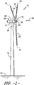
FIG. 1 is a perspective view of a wind turbine according to one embodiment of the present disclosure; -
FIG. 2 illustrates a perspective, internal view of a nacelle of a wind turbine according to one embodiment of the present disclosure; -
FIG. 3 illustrates a schematic diagram of one embodiment of suitable components that may be included in a wind turbine controller according to the present disclosure; -
FIG. 4 illustrates a flow diagram of one embodiment of a method for reducing loads of a wind turbine according to the present disclosure; and -
FIG. 5 illustrates a flow diagram of one embodiment of a method for reducing loads during an idling state of a wind turbine according to the present disclosure. - Reference now will be made in detail to embodiments of the invention, one or more examples of which are illustrated in the drawings. Each example is provided by way of explanation of the invention, not limitation of the invention. In fact, it will be apparent to those skilled in the art that various modifications and variations can be made in the present invention without departing from the scope or spirit of the invention. For instance, features illustrated or described as part of one embodiment can be used with another embodiment to yield a still further embodiment. Thus, it is intended that the present invention covers such modifications and variations as come within the scope of the appended claims and their equivalents.
- Referring now to the drawings,
FIG. 1 illustrates perspective view of one embodiment of awind turbine 10 according to the present disclosure. As shown, thewind turbine 10 includes atower 12 extending from asupport surface 14, anacelle 16 mounted on thetower 12, and arotor 18 coupled to thenacelle 16. Therotor 18 includes arotatable hub 20 and at least onerotor blade 22 coupled to and extending outwardly from thehub 20. For example, in the illustrated embodiment, therotor 18 includes threerotor blades 22. However, in an alternative embodiment, therotor 18 may include more or less than threerotor blades 22. Eachrotor blade 22 may be spaced about thehub 20 to facilitate rotating therotor 18 to enable kinetic energy to be transferred from the wind into usable mechanical energy, and subsequently, electrical energy. For instance, thehub 20 may be rotatably coupled to an electric generator 24 (FIG. 2 ) positioned within thenacelle 16 to permit electrical energy to be produced. - Referring now to
FIG. 2 , a simplified, internal view of one embodiment of thenacelle 16 of thewind turbine 10 is illustrated. As shown, agenerator 24 may be disposed within thenacelle 16. In general, thegenerator 24 may be coupled to therotor 18 of thewind turbine 10 for generating electrical power from the rotational energy generated by therotor 18. For example, therotor 18 may include amain shaft 40 coupled to thehub 20 for rotation therewith. Thegenerator 24 may then be coupled to themain shaft 40 such that rotation of themain shaft 40 drives thegenerator 24. For instance, in the illustrated embodiment, thegenerator 24 includes agenerator shaft 42 rotatably coupled to themain shaft 40 through agearbox 44. However, in other embodiments, it should be appreciated that thegenerator shaft 42 may be rotatably coupled directly to themain shaft 40. Alternatively, thegenerator 24 may be directly rotatably coupled to themain shaft 40. - It should be appreciated that the
main shaft 40 may generally be supported within thenacelle 16 by a support frame orbedplate 46 positioned atop thewind turbine tower 12. For example, themain shaft 40 may be supported by thebedplate 46 via a pair of pillow blocks 48, 50 mounted to thebedplate 46. - As shown in
FIGS. 1 and2 , thewind turbine 10 may also include a turbine control system or aturbine controller 26 within thenacelle 16. For example, as shown inFIG. 2 , theturbine controller 26 is disposed within acontrol cabinet 52 mounted to a portion of thenacelle 16. However, it should be appreciated that theturbine controller 26 may be disposed at any location on or in thewind turbine 10, at any location on thesupport surface 14 or generally at any other location. Theturbine controller 26 may generally be configured to control the various operating modes (e.g., start-up or shut-down sequences) and/or components of thewind turbine 10. - In addition, as shown in
FIG. 2 , one ormore sensors wind turbine 10. More specifically, as shown, ablade sensor 57 may be configured with one or more of therotor blades 22 to monitor therotor blades 22, e.g. for faults and/or loads, which is described in more detail herein. In addition to being a physical sensor mounted to the one or more of therotor blades 22, the faults may be monitored via a limit switch, as well as non-physical parameters such as an acceleration, a status message from the controller communication loss, an encoder failure, a blade position angle, an actual versus commanded pitch angle, or similar. It should also be appreciated that, as used herein, the term "monitor" and variations thereof indicates that the various sensors of thewind turbine 10 may be configured to provide a direct measurement of the parameters being monitored or an indirect measurement of such parameters. Thus, the sensors described herein may, for example, be used to generate signals relating to the parameter being monitored, which can then be utilized by thecontroller 26 to determine the condition. - Further, as shown, a
wind sensor 58 may be provided on thewind turbine 10. Thewind sensor 58, which may for example be a wind vane, and anemometer, and LIDAR sensor, or another suitable sensor, may measure wind speed and direction. As such, thesensors controller 26, and may provide related information to thecontroller 26. For example, yawing of thewind turbine 10 may occur due to sensing of changes in thewind direction 28, in order to maintain alignment of thewind turbine 10 with thewind direction 28. In addition, yawing of thewind turbine 10 may occur due to sensing a rotor blade fault, which is described in more detail herein. - Further, the
turbine controller 26 may also be communicatively coupled to various components of thewind turbine 10 for generally controlling thewind turbine 10 and/or such components. For example, theturbine controller 26 may be communicatively coupled to the yaw drive mechanism(s) 38 of thewind turbine 10 for controlling and/or altering the yaw direction of thenacelle 16 relative to the direction 28 (FIG. 1 ) of the wind. Further, as thedirection 28 of the wind changes, theturbine controller 26 may be configured to control a yaw angle of thenacelle 16 about ayaw axis 36 to position therotor blades 22 with respect to thedirection 28 of the wind, thereby controlling the loads acting on thewind turbine 10. For example, theturbine controller 26 may be configured to transmit control signals/commands to a yaw drive mechanism 38 (FIG. 2 ) of thewind turbine 10, via a yaw controller or direct transmission, such that thenacelle 16 may be rotated about theyaw axis 36 via ayaw bearing 56. - Similarly, the
turbine controller 26 may also be communicatively coupled to eachpitch adjustment mechanism 32 of the wind turbine 10 (one of which is shown) through thepitch controller 30 for controlling and/or altering the pitch angle of the rotor blades 22 (i.e., an angle that determines a perspective of therotor blades 22 with respect to thedirection 28 of the wind). For instance, theturbine controller 26 and/or thepitch controller 30 may be configured to transmit a control signal/command to eachpitch adjustment mechanism 32 such that one or more actuators (not shown) of thepitch adjustment mechanism 32 may be utilized to adjust the pitch angle of therotor blades 22 by rotating theblades 22 along their pitch axes 34 via apitch bearing 54. Theturbine controller 26 may control the pitch angle of therotor blades 22, either individually or simultaneously, by transmitting suitable control signals/commands to a pitch controller of thewind turbine 10, which may be configured to control the operation of a plurality of pitch drives or pitch adjustment mechanisms 32 (FIG. 2 ) of the wind turbine, or by directly controlling the operation of the plurality of pitch drives or pitch adjustment mechanisms. - Referring now to
FIG. 3 , there is illustrated a block diagram of one embodiment of suitable components that may be included within thecontroller 26 according to the present disclosure. As shown, thecontroller 26 may include one or more processor(s) 60 and associated memory device(s) 62 configured to perform a variety of computer-implemented functions (e.g., performing the methods, steps, calculations and the like and storing relevant data as disclosed herein). Additionally, thecontroller 26 may also include acommunications module 64 to facilitate communications between thecontroller 26 and the various components of thewind turbine 10. Further, thecommunications module 64 may include a sensor interface 66 (e.g., one or more analog-to-digital converters) to permit signals transmitted from one ormore sensors processors 60. It should be appreciated that thesensors communications module 64 using any suitable means. For example, as shown inFIG. 3 , thesensors sensor interface 66 via a wired connection. However, in other embodiments, thesensors sensor interface 66 via a wireless connection, such as by using any suitable wireless communications protocol known in the art. - As used herein, the term "processor" refers not only to integrated circuits referred to in the art as being included in a computer, but also refers to a controller, a microcontroller, a microcomputer, a programmable logic controller (PLC), an application specific integrated circuit, and other programmable circuits. Additionally, the memory device(s) 62 may generally comprise memory element(s) including, but not limited to, computer readable medium (e.g., random access memory (RAM)), computer readable non-volatile medium (e.g., a flash memory), a floppy disk, a compact disc-read only memory (CD-ROM), a magnetooptical disk (MOD), a digital versatile disc (DVD) and/or other suitable memory elements. Such memory device(s) 62 may generally be configured to store suitable computer-readable instructions that, when implemented by the processor(s) 60, configure the
controller 26 to perform various functions including, but not limited to, transmitting suitable control signals to implement corrective action(s) in response to a distance signal exceeding a predetermined threshold as described herein, as well as various other suitable computer-implemented functions. - As discussed above, a
wind turbine 10, such as thenacelle 16 thereof, may rotate about theyaw axis 36 as required. In particular, rotation about theyaw axis 36 may occur due to changes in thewind direction 28, such that therotor 18 is aligned with thewind direction 28. For example, when thewind turbine 10 is in an idling state, thecontroller 26 actively tracks the wind direction to provide better alignment to the wind and minimize start-up delays when the wind speed increases or decreases back into the operating range. However, in a situation where thewind turbine 10 is faulted and one or more of therotor blades 22 is prevented from rotating (unlike the normal idling situation), there are limited benefits to tracking the wind because repair will be required before restarting thewind turbine 10. Thus, in such situations, theturbine controller 26 is configured to implement a control strategy to reduce the drag force on the faulted rotor blade so as to reduce loads thereon and/or to prevent rotor imbalance. - More specifically, as shown in
FIG. 4 , a flow diagram of one embodiment of amethod 100 for reducing loads of thewind turbine 10 is illustrated. As shown at 102, themethod 100 includes monitoring one or more of therotor blades 22 of thewind turbine 10 for faults, e.g. via theturbine controller 26. In one embodiment, the faults described herein may include a pitch bearing fault, a pitch drive mechanism fault, an electrical fault, and/or any other fault, error, or defect e.g. that prevents one of therotor blades 22 from operating normally. In addition, the faults described herein may also be caused by maintenance being performed on one or more of therotor blades 22. - In certain embodiments, the
rotor blades 22 may be monitored via one or more sensors, e.g. viasensor 57. As shown at 104, thecontroller 26 is configured to determine whether a fault is detected. If a fault is detected, as shown at 106, thecontroller 26 is configured to determine an operational status of thewind turbine 10. As shown at 108, thecontroller 26 is also configured to determine if a predetermined operational status is present at the same time the fault is present. More specifically, the predetermined operational status of thewind turbine 10 may include an idling state or a parked state of thewind turbine 10. As used herein, the "idling state" of thewind turbine 10 generally refers to the operational state where, due to lack of wind or some other operational conditions (e.g. faults), therotatable hub 20 of thewind turbine 10 is allowed to rotate (i.e. idle) at low rotational speeds, e.g. around 0.2 rpm, rather than being stopped completely. In contrast, a "parked state" of thewind turbine 10 generally refers to the operational state where therotatable hub 20 is stopped and prevented from rotating. - If one of the predetermined operational statuses mentioned above are present at the time of the rotor blade fault, as shown at 110, the
controller 26 actively yaws thenacelle 16 of thewind turbine 10 away from an incoming wind direction (as represented byarrow 28 ofFIG. 1 ) until either the fault is corrected or the operational status changes. Accordingly, actively yawing out of the wind in these situations provides substantial loads reduction. - In yet another embodiment, the
controller 26 may also be configured to actively pitch the remainingrotor blades 22 of the wind turbine 10 (i.e. therotor blades 22 unaffected by the fault) so as to reduce loads. It should be understood that such pitching may be implemented by thecontroller 26 in combination with yawing thenacelle 16 out of the wind or as a separate loads reduction action. - In addition, in several embodiments, the
controller 26 is configured to determine a predetermined yaw offset for yawing thenacelle 16. For example, in certain embodiments, the predetermined yaw offset may include a fixed value. In such embodiments, the predetermined yaw offset may be about ninety degrees (90°), plus or minus from about one degree (1°) to about thirty degrees (60°) from the starting 90° reference point. In alternative embodiments, the predetermined yaw offset may vary as a function of the faulted pitch angle of therotor blade 22 and/or the wind turbine type. In additional embodiments, the predetermined yaw offset may vary as a function of wind speed, density, rotor imbalance, and/or vibrations of thewind turbine 10, e.g. as detected by one or more vibration sensors. As such, themethod 100 may include maintaining the predetermined yaw offset for as long as the rotor blade fault and the predetermined operational status remain present. - It should also be understood that if no fault is detected, the
controller 26 is configured to continuously monitor the incoming wind direction, e.g. during the idling state, and yaw thenacelle 16 into the incoming wind direction to provide improved alignment to the wind with minimal start-up delays when the wind speed increases or decreases back into the operating range. - Referring now to
FIG. 5 , a flow diagram of one embodiment of amethod 200 for reducing loads of thewind turbine 10 during an idling state where one or more of therotor blades 22 is also prevented from rotating is illustrated. As shown at 202, themethod 100 includes monitoring movement of therotor blade 22 of thewind turbine 10 via thecontroller 26. As shown at 204, thecontroller 26 determines whether therotor blade 22 is able to rotate. For example, in one embodiment, therotor blade 22 may become unable to rotate due to a pitch bearing fault, a pitch drive mechanism fault, an electrical fault, and/or a maintenance issue. As shown at 206, if therotor blade 22 becomes unable to rotate, thecontroller 26 actively yaws thenacelle 16 of thewind turbine 10 away from theincoming wind 28 until therotor blade 22 is able to rotate again, i.e. the fault is cleared or repaired and/or the maintenance issue is addressed. - This written description uses examples to disclose the invention, including the best mode, and also to enable any person skilled in the art to practice the invention, including making and using any devices or systems and performing any incorporated methods. The patentable scope of the invention is defined by the claims, and may include other examples that occur to those skilled in the art. Such other examples are intended to be within the scope of the claims if they include structural elements that do not differ from the literal language of the claims, or if they include equivalent structural elements with insubstantial differences from the literal languages of the claims.
Reference Character Component 10 Wind Turbine 12 Tower 14 Surface 16 Nacelle 18 Rotor 20 Rotatable Hub 22 Rotor Blade 24 Generator 26 Turbine Controller 28 Direction 32 Pitch Adjustment Mechanisms 34 Pitch Axes 36 Yaw Axis 38 Yaw Drive Mechanism 40 Main Shaft 42 Generator Shaft 44 Gearbox 46 Bedplate 48 Pillow blocks 50 Pillow Blocks 52 Control Cabinet 54 Pitch Bearing 56 Yaw Bearing 57 Sensor 58 Sensor 60 Processor(s) 62 Memory Device(s) 64 Communications Module 66 Sensor Interface 100 Method 102 Method Step 104 Method Step 106 Method Step 108 Method Step 110 Method Step 200 Method 202 Method Step 204 Method Step 206 Method Step
Claims (20)
- A method for reducing loads of a wind turbine, the method comprising:monitoring, via a turbine controller, a pitch system of the rotor blade of the wind turbine for faults;if a fault is detected, determining an operational status of the wind turbine; and,if a predetermined operational status is present at the same time the fault is present, actively yawing a nacelle of the wind turbine away from an incoming wind direction until at least one of the fault is corrected or the operational status changes.
- The method of claim 1, wherein the faults comprise at least one of a pitch bearing fault, a pitch drive mechanism fault, or an electrical fault.
- The method of claim 1, further comprising determining a predetermined yaw offset for yawing the nacelle.
- The method of claim 3, wherein the predetermined yaw offset is a fixed value.
- The method of claim 4, wherein the predetermined yaw offset comprises about ninety degrees (90°) plus or minus from about one degree (1°) to about thirty degrees (60°).
- The method of claim 3, wherein the predetermined yaw offset varies as a function of at least one of a pitch angle of the rotor blade, wind speed, density, rotor imbalance, or vibration of the wind turbine.
- The method of claim 3, further comprising maintaining the predetermined yaw offset for as long as the fault and the predetermined operational status remain present.
- The method of claim 1, wherein the predetermined operational status of the wind turbine comprises at least one of an idling state or a parked state.
- The method of claim 8, further comprising continuously monitoring the incoming wind direction during the idling state and yawing the nacelle into the incoming wind direction if no fault is detected.
- The method of claim 1, further comprising pitching remaining rotor blades of the wind turbine if the fault is detected in the rotor blade.
- A system for reducing loads of a wind turbine during a rotor blade fault, the system comprising:at least one sensor configured for monitoring a rotor blade of the wind turbine;a controller communicatively coupled to the at least one sensor, the controller comprising at least one processor configured to perform one or more operations, the one or more operations comprising:determining an operational status of the wind turbine if a rotor blade fault is detected via the at least sensor; and,if a predetermined operational status is present at the same time the fault is present, actively yawing a nacelle of the wind turbine away from an incoming wind direction until at least one of the fault is corrected or the operational status changes.
- The system of claim 11, wherein the rotor blade fault comprises at least one of a pitch bearing fault, a pitch drive mechanism fault, or an electrical fault.
- The method of claim 11, wherein the processor is further configured to determine a predetermined yaw offset for yawing the nacelle.
- A method for reducing loads during an idling state of a wind turbine, the method comprising:monitoring, via a turbine controller, movement of a rotor blade of the wind turbine during the idling state; and,if the rotor blade becomes unable to rotate, actively yawing a nacelle of the wind turbine away from an incoming wind direction until the rotor blade is able to rotate again.
- The method of claim 14, wherein the rotor blade becomes unable to rotate due to at least one of a pitch bearing fault, a pitch drive mechanism fault, an electrical fault, or a maintenance issue.
- The method of claim 14, further comprising determining a predetermined yaw offset for yawing the nacelle.
- The method of claim 16, wherein the predetermined yaw offset is a fixed value.
- The method of claim 16, wherein the predetermined yaw offset varies as a function of a pitch angle of the rotor blade.
- The method of claim 16, further comprising maintaining the predetermined yaw offset for as long as the rotor blade remains unable to rotate.
- The method of claim 14, further comprising continuously monitoring the incoming wind direction during the idling state and yawing the nacelle into the incoming wind direction as long as the rotor blade is able to rotate.
Priority Applications (4)
| Application Number | Priority Date | Filing Date | Title |
|---|---|---|---|
| ES17382312T ES2929735T3 (en) | 2017-05-30 | 2017-05-30 | Method for reducing loads during an idling or stopped state of a wind turbine by means of yaw displacement |
| DK17382312.1T DK3409940T3 (en) | 2017-05-30 | 2017-05-30 | PROCEDURE FOR REDUCING LOADS DURING STANDBY OR PARKED CONDITION FOR A WIND TURBINE VIA YAW OFFSET |
| EP17382312.1A EP3409940B1 (en) | 2017-05-30 | 2017-05-30 | Method for reducing loads during an idling or parked state of a wind turbine via yaw offset |
| US15/984,936 US10871144B2 (en) | 2017-05-30 | 2018-05-21 | System and method for reducing loads during an idling or parked state of a wind turbine via yaw offset |
Applications Claiming Priority (1)
| Application Number | Priority Date | Filing Date | Title |
|---|---|---|---|
| EP17382312.1A EP3409940B1 (en) | 2017-05-30 | 2017-05-30 | Method for reducing loads during an idling or parked state of a wind turbine via yaw offset |
Publications (2)
| Publication Number | Publication Date |
|---|---|
| EP3409940A1 true EP3409940A1 (en) | 2018-12-05 |
| EP3409940B1 EP3409940B1 (en) | 2022-08-24 |
Family
ID=59077995
Family Applications (1)
| Application Number | Title | Priority Date | Filing Date |
|---|---|---|---|
| EP17382312.1A Active EP3409940B1 (en) | 2017-05-30 | 2017-05-30 | Method for reducing loads during an idling or parked state of a wind turbine via yaw offset |
Country Status (4)
| Country | Link |
|---|---|
| US (1) | US10871144B2 (en) |
| EP (1) | EP3409940B1 (en) |
| DK (1) | DK3409940T3 (en) |
| ES (1) | ES2929735T3 (en) |
Cited By (7)
| Publication number | Priority date | Publication date | Assignee | Title |
|---|---|---|---|---|
| CN109707563A (en) * | 2018-12-26 | 2019-05-03 | 北京金风科创风电设备有限公司 | Variable pitch driver restart control method and device and wind generating set |
| EP3597906A1 (en) * | 2018-07-17 | 2020-01-22 | General Electric Company | System and method for reducing loads of a wind turbine when a rotor blade becomes stuck |
| CN111749846A (en) * | 2020-06-09 | 2020-10-09 | 明阳智慧能源集团股份公司 | A method for yaw control of wind turbines |
| EP3875756A1 (en) * | 2020-03-02 | 2021-09-08 | Vestas Wind Systems A/S | Blade pitch control monitoring system for a wind turbine |
| CN114704438A (en) * | 2022-06-02 | 2022-07-05 | 深圳众城卓越科技有限公司 | Wind turbine generator set fault monitoring method and device |
| WO2022166144A1 (en) * | 2021-02-03 | 2022-08-11 | 三一重能股份有限公司 | Yaw control method and apparatus, electronic device, and storage medium |
| CN115951088A (en) * | 2023-03-10 | 2023-04-11 | 南京华盾电力信息安全测评有限公司 | Wind turbine generator anemograph abnormity analysis method |
Families Citing this family (15)
| Publication number | Priority date | Publication date | Assignee | Title |
|---|---|---|---|---|
| US11208986B2 (en) | 2019-06-27 | 2021-12-28 | Uptake Technologies, Inc. | Computer system and method for detecting irregular yaw activity at a wind turbine |
| US10975841B2 (en) * | 2019-08-02 | 2021-04-13 | Uptake Technologies, Inc. | Computer system and method for detecting rotor imbalance at a wind turbine |
| CN113027681B (en) * | 2019-12-25 | 2022-06-28 | 新疆金风科技股份有限公司 | Wind turbine operation control method and device, computer equipment |
| EP3859144A1 (en) * | 2020-01-29 | 2021-08-04 | Siemens Gamesa Renewable Energy A/S | Mitigating standstill vibrations of a wind turbine |
| EP3964706B1 (en) * | 2020-09-02 | 2025-05-14 | General Electric Renovables España S.L. | A method for operating a wind turbine and a wind turbine |
| CN112576453B (en) * | 2020-11-12 | 2021-11-19 | 南京力思拓能源科技有限公司 | Wind driven generator anemorumbometer state evaluation method and system based on Doppler laser radar technology |
| CN115506956A (en) * | 2021-06-22 | 2022-12-23 | 新疆金风科技股份有限公司 | Propeller carding control method, device, controller and medium for wind power generating set |
| CN113294292B (en) * | 2021-06-30 | 2022-07-05 | 北京金风科创风电设备有限公司 | Control method, device, system, equipment and medium of wind generating set |
| EP4130465A1 (en) * | 2021-08-02 | 2023-02-08 | Siemens Gamesa Renewable Energy A/S | Method of operating a wind turbine in an active idle mode with faulty blades |
| CN113606085A (en) * | 2021-08-23 | 2021-11-05 | 哈电风能有限公司 | Yaw control method, controller and system based on failure condition of variable pitch system |
| EP4174312A1 (en) | 2021-11-02 | 2023-05-03 | Siemens Gamesa Renewable Energy A/S | Yawing a wind turbine during idling |
| US11879425B2 (en) * | 2021-12-08 | 2024-01-23 | Ge Infrastructure Technology Llc | System and method for controlling blade pitch of wind turbine rotor blades in an idling state of the rotor hub |
| US11754039B1 (en) | 2022-08-17 | 2023-09-12 | General Electric Renovables Espana, S.L. | Load dependent autonomous yaw control for a wind turbine |
| EP4455477A1 (en) | 2023-04-26 | 2024-10-30 | Siemens Gamesa Renewable Energy A/S | Active damping for an offshore wind turbine during idling |
| CN116557231A (en) * | 2023-05-29 | 2023-08-08 | 中车株洲电力机车研究所有限公司 | A wind turbine yaw slip fault diagnosis method and early warning method |
Citations (2)
| Publication number | Priority date | Publication date | Assignee | Title |
|---|---|---|---|---|
| EP1990539A1 (en) * | 2006-02-28 | 2008-11-12 | Mitsubishi Heavy Industries, Ltd. | Wind power generation system, and control method therefor |
| US20090081041A1 (en) * | 2007-09-22 | 2009-03-26 | Nordex Energy Gmbh | Method for controlling a wind energy plant |
Family Cites Families (14)
| Publication number | Priority date | Publication date | Assignee | Title |
|---|---|---|---|---|
| DE10058076C2 (en) | 2000-11-23 | 2003-06-12 | Aloys Wobben | Method for controlling a wind energy plant |
| DE10320087B4 (en) * | 2003-05-05 | 2005-04-28 | Aloys Wobben | Process for operating a wind park consisting of a number of wind energy plants comprises controlling the operations of each plant until the net electrical power is supplied up to a predetermined maximum value |
| EP2450568B1 (en) | 2005-05-31 | 2018-04-18 | Hitachi, Ltd. | Horizontal axis wind turbine |
| ES2561504T5 (en) | 2009-09-28 | 2019-05-13 | Vestas Wind Sys As | Reduction of stopping load of a wind turbine |
| US8025476B2 (en) * | 2009-09-30 | 2011-09-27 | General Electric Company | System and methods for controlling a wind turbine |
| KR101027055B1 (en) * | 2009-12-30 | 2011-04-11 | 윤진목 | Wind power generator |
| US8215896B2 (en) * | 2010-12-20 | 2012-07-10 | General Electric Company | Apparatus and method for operation of an off-shore wind turbine |
| DK177422B1 (en) | 2011-05-06 | 2013-04-22 | Envision Energy Denmark Aps | A Wind Turbine and Associated Control Method |
| US20150086357A1 (en) * | 2013-09-24 | 2015-03-26 | General Electric Company | Wind turbine and method for adjusting yaw bias in wind turbine |
| WO2015192852A1 (en) * | 2014-06-20 | 2015-12-23 | Mita-Teknik A/S | System for dynamic pitch control |
| DK3128170T3 (en) | 2015-08-06 | 2018-06-14 | Nordex Energy Gmbh | Wind energy system with an azimuth drive |
| US11002250B2 (en) * | 2016-02-12 | 2021-05-11 | Vestas Wind Systems A/S | Controlling bearing wear |
| DK201670197A1 (en) * | 2016-04-04 | 2017-10-23 | Mita-Teknik As | A system and a method for optimal yaw control |
| US11168662B2 (en) * | 2016-04-13 | 2021-11-09 | Vestas Wind Systems A/S | Control method for a wind turbine |
-
2017
- 2017-05-30 DK DK17382312.1T patent/DK3409940T3/en active
- 2017-05-30 EP EP17382312.1A patent/EP3409940B1/en active Active
- 2017-05-30 ES ES17382312T patent/ES2929735T3/en active Active
-
2018
- 2018-05-21 US US15/984,936 patent/US10871144B2/en active Active
Patent Citations (2)
| Publication number | Priority date | Publication date | Assignee | Title |
|---|---|---|---|---|
| EP1990539A1 (en) * | 2006-02-28 | 2008-11-12 | Mitsubishi Heavy Industries, Ltd. | Wind power generation system, and control method therefor |
| US20090081041A1 (en) * | 2007-09-22 | 2009-03-26 | Nordex Energy Gmbh | Method for controlling a wind energy plant |
Cited By (11)
| Publication number | Priority date | Publication date | Assignee | Title |
|---|---|---|---|---|
| EP3597906A1 (en) * | 2018-07-17 | 2020-01-22 | General Electric Company | System and method for reducing loads of a wind turbine when a rotor blade becomes stuck |
| US10808680B2 (en) | 2018-07-17 | 2020-10-20 | General Electric Company | System and method for reducing loads of a wind turbine when a rotor blade becomes stuck |
| CN109707563A (en) * | 2018-12-26 | 2019-05-03 | 北京金风科创风电设备有限公司 | Variable pitch driver restart control method and device and wind generating set |
| CN109707563B (en) * | 2018-12-26 | 2021-06-11 | 北京金风科创风电设备有限公司 | Variable pitch driver restart control method and device and wind generating set |
| EP3875756A1 (en) * | 2020-03-02 | 2021-09-08 | Vestas Wind Systems A/S | Blade pitch control monitoring system for a wind turbine |
| US11549486B2 (en) | 2020-03-02 | 2023-01-10 | Vestas Wind Systems A/S | Blade pitch control monitoring system for a wind turbine |
| CN111749846A (en) * | 2020-06-09 | 2020-10-09 | 明阳智慧能源集团股份公司 | A method for yaw control of wind turbines |
| WO2022166144A1 (en) * | 2021-02-03 | 2022-08-11 | 三一重能股份有限公司 | Yaw control method and apparatus, electronic device, and storage medium |
| CN114704438A (en) * | 2022-06-02 | 2022-07-05 | 深圳众城卓越科技有限公司 | Wind turbine generator set fault monitoring method and device |
| CN115951088A (en) * | 2023-03-10 | 2023-04-11 | 南京华盾电力信息安全测评有限公司 | Wind turbine generator anemograph abnormity analysis method |
| CN115951088B (en) * | 2023-03-10 | 2023-08-25 | 南京南自华盾数字技术有限公司 | Wind turbine anemometer anomaly analysis method |
Also Published As
| Publication number | Publication date |
|---|---|
| US10871144B2 (en) | 2020-12-22 |
| DK3409940T3 (en) | 2022-09-19 |
| ES2929735T3 (en) | 2022-12-01 |
| EP3409940B1 (en) | 2022-08-24 |
| US20180347542A1 (en) | 2018-12-06 |
Similar Documents
| Publication | Publication Date | Title |
|---|---|---|
| US10871144B2 (en) | System and method for reducing loads during an idling or parked state of a wind turbine via yaw offset | |
| EP3597904B1 (en) | System and method for reducing wind turbine loads by yawing the nacelle to a predetermined position based on rotor imbalance | |
| EP3597905B1 (en) | System and method for detecting a pitch fault in a wind turbine via voltage, current, torque, or force monitoring | |
| US10830208B2 (en) | System and method for mitigating blade run-away loads in the event of a pitch system failure | |
| EP3597910B1 (en) | System and method for reducing loads during an idling or parked state of a wind turbine with a stuck rotor blade | |
| EP3581795B1 (en) | System and method for controlling a wind turbine to minimize rotor blade damage | |
| EP3543523B1 (en) | System and method for testing an energy storage device of a wind turbine pitch system | |
| US10156224B2 (en) | System and method for controlling a wind turbine | |
| EP4325047B1 (en) | Load dependent autonomous yaw control for a wind turbine | |
| CN112005009B (en) | System and method for improved overspeed monitoring of wind turbines operating at reduced rotor speeds | |
| US10316822B2 (en) | System and method for improved overspeed monitoring of a wind turbine operating at reduced rotor speeds | |
| EP3643916B1 (en) | System and method for monitoring rotor blade condition of wind turbines | |
| EP3597906B1 (en) | System and method for reducing loads of a wind turbine when a rotor blade becomes stuck |
Legal Events
| Date | Code | Title | Description |
|---|---|---|---|
| PUAI | Public reference made under article 153(3) epc to a published international application that has entered the european phase |
Free format text: ORIGINAL CODE: 0009012 |
|
| STAA | Information on the status of an ep patent application or granted ep patent |
Free format text: STATUS: THE APPLICATION HAS BEEN PUBLISHED |
|
| AK | Designated contracting states |
Kind code of ref document: A1 Designated state(s): AL AT BE BG CH CY CZ DE DK EE ES FI FR GB GR HR HU IE IS IT LI LT LU LV MC MK MT NL NO PL PT RO RS SE SI SK SM TR |
|
| AX | Request for extension of the european patent |
Extension state: BA ME |
|
| STAA | Information on the status of an ep patent application or granted ep patent |
Free format text: STATUS: REQUEST FOR EXAMINATION WAS MADE |
|
| 17P | Request for examination filed |
Effective date: 20190604 |
|
| RBV | Designated contracting states (corrected) |
Designated state(s): AL AT BE BG CH CY CZ DE DK EE ES FI FR GB GR HR HU IE IS IT LI LT LU LV MC MK MT NL NO PL PT RO RS SE SI SK SM TR |
|
| STAA | Information on the status of an ep patent application or granted ep patent |
Free format text: STATUS: EXAMINATION IS IN PROGRESS |
|
| 17Q | First examination report despatched |
Effective date: 20201030 |
|
| GRAP | Despatch of communication of intention to grant a patent |
Free format text: ORIGINAL CODE: EPIDOSNIGR1 |
|
| STAA | Information on the status of an ep patent application or granted ep patent |
Free format text: STATUS: GRANT OF PATENT IS INTENDED |
|
| INTG | Intention to grant announced |
Effective date: 20220428 |
|
| GRAS | Grant fee paid |
Free format text: ORIGINAL CODE: EPIDOSNIGR3 |
|
| GRAA | (expected) grant |
Free format text: ORIGINAL CODE: 0009210 |
|
| STAA | Information on the status of an ep patent application or granted ep patent |
Free format text: STATUS: THE PATENT HAS BEEN GRANTED |
|
| AK | Designated contracting states |
Kind code of ref document: B1 Designated state(s): AL AT BE BG CH CY CZ DE DK EE ES FI FR GB GR HR HU IE IS IT LI LT LU LV MC MK MT NL NO PL PT RO RS SE SI SK SM TR |
|
| REG | Reference to a national code |
Ref country code: CH Ref legal event code: EP |
|
| REG | Reference to a national code |
Ref country code: DE Ref legal event code: R096 Ref document number: 602017060947 Country of ref document: DE |
|
| REG | Reference to a national code |
Ref country code: IE Ref legal event code: FG4D |
|
| REG | Reference to a national code |
Ref country code: AT Ref legal event code: REF Ref document number: 1513798 Country of ref document: AT Kind code of ref document: T Effective date: 20220915 |
|
| REG | Reference to a national code |
Ref country code: DK Ref legal event code: T3 Effective date: 20220914 |
|
| REG | Reference to a national code |
Ref country code: ES Ref legal event code: FG2A Ref document number: 2929735 Country of ref document: ES Kind code of ref document: T3 Effective date: 20221201 |
|
| REG | Reference to a national code |
Ref country code: LT Ref legal event code: MG9D |
|
| REG | Reference to a national code |
Ref country code: NL Ref legal event code: MP Effective date: 20220824 |
|
| PG25 | Lapsed in a contracting state [announced via postgrant information from national office to epo] |
Ref country code: SE Free format text: LAPSE BECAUSE OF FAILURE TO SUBMIT A TRANSLATION OF THE DESCRIPTION OR TO PAY THE FEE WITHIN THE PRESCRIBED TIME-LIMIT Effective date: 20220824 Ref country code: RS Free format text: LAPSE BECAUSE OF FAILURE TO SUBMIT A TRANSLATION OF THE DESCRIPTION OR TO PAY THE FEE WITHIN THE PRESCRIBED TIME-LIMIT Effective date: 20220824 Ref country code: PT Free format text: LAPSE BECAUSE OF FAILURE TO SUBMIT A TRANSLATION OF THE DESCRIPTION OR TO PAY THE FEE WITHIN THE PRESCRIBED TIME-LIMIT Effective date: 20221226 Ref country code: NO Free format text: LAPSE BECAUSE OF FAILURE TO SUBMIT A TRANSLATION OF THE DESCRIPTION OR TO PAY THE FEE WITHIN THE PRESCRIBED TIME-LIMIT Effective date: 20221124 Ref country code: NL Free format text: LAPSE BECAUSE OF FAILURE TO SUBMIT A TRANSLATION OF THE DESCRIPTION OR TO PAY THE FEE WITHIN THE PRESCRIBED TIME-LIMIT Effective date: 20220824 Ref country code: LV Free format text: LAPSE BECAUSE OF FAILURE TO SUBMIT A TRANSLATION OF THE DESCRIPTION OR TO PAY THE FEE WITHIN THE PRESCRIBED TIME-LIMIT Effective date: 20220824 Ref country code: LT Free format text: LAPSE BECAUSE OF FAILURE TO SUBMIT A TRANSLATION OF THE DESCRIPTION OR TO PAY THE FEE WITHIN THE PRESCRIBED TIME-LIMIT Effective date: 20220824 Ref country code: FI Free format text: LAPSE BECAUSE OF FAILURE TO SUBMIT A TRANSLATION OF THE DESCRIPTION OR TO PAY THE FEE WITHIN THE PRESCRIBED TIME-LIMIT Effective date: 20220824 |
|
| REG | Reference to a national code |
Ref country code: AT Ref legal event code: MK05 Ref document number: 1513798 Country of ref document: AT Kind code of ref document: T Effective date: 20220824 |
|
| PG25 | Lapsed in a contracting state [announced via postgrant information from national office to epo] |
Ref country code: PL Free format text: LAPSE BECAUSE OF FAILURE TO SUBMIT A TRANSLATION OF THE DESCRIPTION OR TO PAY THE FEE WITHIN THE PRESCRIBED TIME-LIMIT Effective date: 20220824 Ref country code: IS Free format text: LAPSE BECAUSE OF FAILURE TO SUBMIT A TRANSLATION OF THE DESCRIPTION OR TO PAY THE FEE WITHIN THE PRESCRIBED TIME-LIMIT Effective date: 20221224 Ref country code: HR Free format text: LAPSE BECAUSE OF FAILURE TO SUBMIT A TRANSLATION OF THE DESCRIPTION OR TO PAY THE FEE WITHIN THE PRESCRIBED TIME-LIMIT Effective date: 20220824 Ref country code: GR Free format text: LAPSE BECAUSE OF FAILURE TO SUBMIT A TRANSLATION OF THE DESCRIPTION OR TO PAY THE FEE WITHIN THE PRESCRIBED TIME-LIMIT Effective date: 20221125 |
|
| PG25 | Lapsed in a contracting state [announced via postgrant information from national office to epo] |
Ref country code: SM Free format text: LAPSE BECAUSE OF FAILURE TO SUBMIT A TRANSLATION OF THE DESCRIPTION OR TO PAY THE FEE WITHIN THE PRESCRIBED TIME-LIMIT Effective date: 20220824 Ref country code: RO Free format text: LAPSE BECAUSE OF FAILURE TO SUBMIT A TRANSLATION OF THE DESCRIPTION OR TO PAY THE FEE WITHIN THE PRESCRIBED TIME-LIMIT Effective date: 20220824 Ref country code: CZ Free format text: LAPSE BECAUSE OF FAILURE TO SUBMIT A TRANSLATION OF THE DESCRIPTION OR TO PAY THE FEE WITHIN THE PRESCRIBED TIME-LIMIT Effective date: 20220824 Ref country code: AT Free format text: LAPSE BECAUSE OF FAILURE TO SUBMIT A TRANSLATION OF THE DESCRIPTION OR TO PAY THE FEE WITHIN THE PRESCRIBED TIME-LIMIT Effective date: 20220824 |
|
| REG | Reference to a national code |
Ref country code: DE Ref legal event code: R026 Ref document number: 602017060947 Country of ref document: DE |
|
| PLBI | Opposition filed |
Free format text: ORIGINAL CODE: 0009260 |
|
| PG25 | Lapsed in a contracting state [announced via postgrant information from national office to epo] |
Ref country code: SK Free format text: LAPSE BECAUSE OF FAILURE TO SUBMIT A TRANSLATION OF THE DESCRIPTION OR TO PAY THE FEE WITHIN THE PRESCRIBED TIME-LIMIT Effective date: 20220824 Ref country code: EE Free format text: LAPSE BECAUSE OF FAILURE TO SUBMIT A TRANSLATION OF THE DESCRIPTION OR TO PAY THE FEE WITHIN THE PRESCRIBED TIME-LIMIT Effective date: 20220824 |
|
| PLAX | Notice of opposition and request to file observation + time limit sent |
Free format text: ORIGINAL CODE: EPIDOSNOBS2 |
|
| 26 | Opposition filed |
Opponent name: WOBBEN PROPERTIES GMBH Effective date: 20230522 |
|
| PG25 | Lapsed in a contracting state [announced via postgrant information from national office to epo] |
Ref country code: AL Free format text: LAPSE BECAUSE OF FAILURE TO SUBMIT A TRANSLATION OF THE DESCRIPTION OR TO PAY THE FEE WITHIN THE PRESCRIBED TIME-LIMIT Effective date: 20220824 |
|
| P01 | Opt-out of the competence of the unified patent court (upc) registered |
Effective date: 20230530 |
|
| PG25 | Lapsed in a contracting state [announced via postgrant information from national office to epo] |
Ref country code: SI Free format text: LAPSE BECAUSE OF FAILURE TO SUBMIT A TRANSLATION OF THE DESCRIPTION OR TO PAY THE FEE WITHIN THE PRESCRIBED TIME-LIMIT Effective date: 20220824 |
|
| PLBB | Reply of patent proprietor to notice(s) of opposition received |
Free format text: ORIGINAL CODE: EPIDOSNOBS3 |
|
| REG | Reference to a national code |
Ref country code: DE Ref legal event code: R081 Ref document number: 602017060947 Country of ref document: DE Owner name: GENERAL ELECTRIC RENOVABLES ESPANA, S.L., ES Free format text: FORMER OWNER: GENERAL ELECTRIC COMPANY, SCHENECTADY, NY, US Ref legal event code: R082 Ref document number: 602017060947 Ref country code: DE Country of ref document: DE Representative=s name: ZIMMERMANN & PARTNER PATENTANWAELTE MBB, DE |
|
| REG | Reference to a national code |
Ref country code: CH Ref legal event code: PL |
|
| PG25 | Lapsed in a contracting state [announced via postgrant information from national office to epo] |
Ref country code: MC Free format text: LAPSE BECAUSE OF FAILURE TO SUBMIT A TRANSLATION OF THE DESCRIPTION OR TO PAY THE FEE WITHIN THE PRESCRIBED TIME-LIMIT Effective date: 20220824 |
|
| GBPC | Gb: european patent ceased through non-payment of renewal fee |
Effective date: 20230530 |
|
| REG | Reference to a national code |
Ref country code: BE Ref legal event code: MM Effective date: 20230531 |
|
| PG25 | Lapsed in a contracting state [announced via postgrant information from national office to epo] |
Ref country code: MC Free format text: LAPSE BECAUSE OF FAILURE TO SUBMIT A TRANSLATION OF THE DESCRIPTION OR TO PAY THE FEE WITHIN THE PRESCRIBED TIME-LIMIT Effective date: 20220824 Ref country code: LU Free format text: LAPSE BECAUSE OF NON-PAYMENT OF DUE FEES Effective date: 20230530 Ref country code: LI Free format text: LAPSE BECAUSE OF NON-PAYMENT OF DUE FEES Effective date: 20230531 Ref country code: CH Free format text: LAPSE BECAUSE OF NON-PAYMENT OF DUE FEES Effective date: 20230531 |
|
| REG | Reference to a national code |
Ref country code: IE Ref legal event code: MM4A |
|
| REG | Reference to a national code |
Ref country code: DE Ref legal event code: R082 Ref document number: 602017060947 Country of ref document: DE Representative=s name: ZIMMERMANN & PARTNER PATENTANWAELTE MBB, DE |
|
| PG25 | Lapsed in a contracting state [announced via postgrant information from national office to epo] |
Ref country code: IE Free format text: LAPSE BECAUSE OF NON-PAYMENT OF DUE FEES Effective date: 20230530 |
|
| PG25 | Lapsed in a contracting state [announced via postgrant information from national office to epo] |
Ref country code: IE Free format text: LAPSE BECAUSE OF NON-PAYMENT OF DUE FEES Effective date: 20230530 Ref country code: GB Free format text: LAPSE BECAUSE OF NON-PAYMENT OF DUE FEES Effective date: 20230530 |
|
| PG25 | Lapsed in a contracting state [announced via postgrant information from national office to epo] |
Ref country code: IT Free format text: LAPSE BECAUSE OF FAILURE TO SUBMIT A TRANSLATION OF THE DESCRIPTION OR TO PAY THE FEE WITHIN THE PRESCRIBED TIME-LIMIT Effective date: 20220824 Ref country code: FR Free format text: LAPSE BECAUSE OF NON-PAYMENT OF DUE FEES Effective date: 20230531 Ref country code: BE Free format text: LAPSE BECAUSE OF NON-PAYMENT OF DUE FEES Effective date: 20230531 |
|
| REG | Reference to a national code |
Ref country code: ES Ref legal event code: PC2A Owner name: GENERAL ELECTRIC RENOVABLES ESPANA S.L. Effective date: 20240809 |
|
| PG25 | Lapsed in a contracting state [announced via postgrant information from national office to epo] |
Ref country code: BG Free format text: LAPSE BECAUSE OF FAILURE TO SUBMIT A TRANSLATION OF THE DESCRIPTION OR TO PAY THE FEE WITHIN THE PRESCRIBED TIME-LIMIT Effective date: 20220824 |
|
| PG25 | Lapsed in a contracting state [announced via postgrant information from national office to epo] |
Ref country code: BG Free format text: LAPSE BECAUSE OF FAILURE TO SUBMIT A TRANSLATION OF THE DESCRIPTION OR TO PAY THE FEE WITHIN THE PRESCRIBED TIME-LIMIT Effective date: 20220824 |
|
| PLCK | Communication despatched that opposition was rejected |
Free format text: ORIGINAL CODE: EPIDOSNREJ1 |
|
| APAH | Appeal reference modified |
Free format text: ORIGINAL CODE: EPIDOSCREFNO |
|
| APAW | Appeal reference deleted |
Free format text: ORIGINAL CODE: EPIDOSDREFNO |
|
| APBP | Date of receipt of notice of appeal recorded |
Free format text: ORIGINAL CODE: EPIDOSNNOA2O |
|
| APBQ | Date of receipt of statement of grounds of appeal recorded |
Free format text: ORIGINAL CODE: EPIDOSNNOA3O |
|
| RAP2 | Party data changed (patent owner data changed or rights of a patent transferred) |
Owner name: GENERAL ELECTRIC RENOVABLES ESPANA S.L. |
|
| PGFP | Annual fee paid to national office [announced via postgrant information from national office to epo] |
Ref country code: DE Payment date: 20250423 Year of fee payment: 9 |
|
| PGFP | Annual fee paid to national office [announced via postgrant information from national office to epo] |
Ref country code: ES Payment date: 20250602 Year of fee payment: 9 Ref country code: DK Payment date: 20250423 Year of fee payment: 9 |
|
| PG25 | Lapsed in a contracting state [announced via postgrant information from national office to epo] |
Ref country code: CY Free format text: LAPSE BECAUSE OF FAILURE TO SUBMIT A TRANSLATION OF THE DESCRIPTION OR TO PAY THE FEE WITHIN THE PRESCRIBED TIME-LIMIT; INVALID AB INITIO Effective date: 20170530 |
|
| PG25 | Lapsed in a contracting state [announced via postgrant information from national office to epo] |
Ref country code: HU Free format text: LAPSE BECAUSE OF FAILURE TO SUBMIT A TRANSLATION OF THE DESCRIPTION OR TO PAY THE FEE WITHIN THE PRESCRIBED TIME-LIMIT; INVALID AB INITIO Effective date: 20170530 |
|
| PG25 | Lapsed in a contracting state [announced via postgrant information from national office to epo] |
Ref country code: TR Free format text: LAPSE BECAUSE OF FAILURE TO SUBMIT A TRANSLATION OF THE DESCRIPTION OR TO PAY THE FEE WITHIN THE PRESCRIBED TIME-LIMIT Effective date: 20220824 |
|
| RAP4 | Party data changed (patent owner data changed or rights of a patent transferred) |
Owner name: GE VERNOVA RENOVABLES ESPANA, S.L. |
|
| RAP4 | Party data changed (patent owner data changed or rights of a patent transferred) |
Owner name: GE VERNOVA RENOVABLES ESPANA, S.L. |