EP3409932A1 - Fuel injection valve control device - Google Patents
Fuel injection valve control device Download PDFInfo
- Publication number
- EP3409932A1 EP3409932A1 EP16888111.8A EP16888111A EP3409932A1 EP 3409932 A1 EP3409932 A1 EP 3409932A1 EP 16888111 A EP16888111 A EP 16888111A EP 3409932 A1 EP3409932 A1 EP 3409932A1
- Authority
- EP
- European Patent Office
- Prior art keywords
- injection valve
- fuel
- fuel injection
- injected
- fluid
- Prior art date
- Legal status (The legal status is an assumption and is not a legal conclusion. Google has not performed a legal analysis and makes no representation as to the accuracy of the status listed.)
- Granted
Links
Images


Classifications
-
- F—MECHANICAL ENGINEERING; LIGHTING; HEATING; WEAPONS; BLASTING
- F02—COMBUSTION ENGINES; HOT-GAS OR COMBUSTION-PRODUCT ENGINE PLANTS
- F02D—CONTROLLING COMBUSTION ENGINES
- F02D41/00—Electrical control of supply of combustible mixture or its constituents
- F02D41/30—Controlling fuel injection
- F02D41/32—Controlling fuel injection of the low pressure type
- F02D41/34—Controlling fuel injection of the low pressure type with means for controlling injection timing or duration
-
- F—MECHANICAL ENGINEERING; LIGHTING; HEATING; WEAPONS; BLASTING
- F02—COMBUSTION ENGINES; HOT-GAS OR COMBUSTION-PRODUCT ENGINE PLANTS
- F02D—CONTROLLING COMBUSTION ENGINES
- F02D41/00—Electrical control of supply of combustible mixture or its constituents
- F02D41/30—Controlling fuel injection
- F02D41/3011—Controlling fuel injection according to or using specific or several modes of combustion
- F02D41/3017—Controlling fuel injection according to or using specific or several modes of combustion characterised by the mode(s) being used
- F02D41/3023—Controlling fuel injection according to or using specific or several modes of combustion characterised by the mode(s) being used a mode being the stratified charge spark-ignited mode
- F02D41/3029—Controlling fuel injection according to or using specific or several modes of combustion characterised by the mode(s) being used a mode being the stratified charge spark-ignited mode further comprising a homogeneous charge spark-ignited mode
-
- F—MECHANICAL ENGINEERING; LIGHTING; HEATING; WEAPONS; BLASTING
- F02—COMBUSTION ENGINES; HOT-GAS OR COMBUSTION-PRODUCT ENGINE PLANTS
- F02B—INTERNAL-COMBUSTION PISTON ENGINES; COMBUSTION ENGINES IN GENERAL
- F02B23/00—Other engines characterised by special shape or construction of combustion chambers to improve operation
- F02B23/08—Other engines characterised by special shape or construction of combustion chambers to improve operation with positive ignition
- F02B23/10—Other engines characterised by special shape or construction of combustion chambers to improve operation with positive ignition with separate admission of air and fuel into cylinder
-
- F—MECHANICAL ENGINEERING; LIGHTING; HEATING; WEAPONS; BLASTING
- F02—COMBUSTION ENGINES; HOT-GAS OR COMBUSTION-PRODUCT ENGINE PLANTS
- F02D—CONTROLLING COMBUSTION ENGINES
- F02D19/00—Controlling engines characterised by their use of non-liquid fuels, pluralities of fuels, or non-fuel substances added to the combustible mixtures
- F02D19/06—Controlling engines characterised by their use of non-liquid fuels, pluralities of fuels, or non-fuel substances added to the combustible mixtures peculiar to engines working with pluralities of fuels, e.g. alternatively with light and heavy fuel oil, other than engines indifferent to the fuel consumed
- F02D19/0663—Details on the fuel supply system, e.g. tanks, valves, pipes, pumps, rails, injectors or mixers
- F02D19/0686—Injectors
- F02D19/0692—Arrangement of multiple injectors per combustion chamber
-
- F—MECHANICAL ENGINEERING; LIGHTING; HEATING; WEAPONS; BLASTING
- F02—COMBUSTION ENGINES; HOT-GAS OR COMBUSTION-PRODUCT ENGINE PLANTS
- F02D—CONTROLLING COMBUSTION ENGINES
- F02D21/00—Controlling engines characterised by their being supplied with non-airborne oxygen or other non-fuel gas
- F02D21/06—Controlling engines characterised by their being supplied with non-airborne oxygen or other non-fuel gas peculiar to engines having other non-fuel gas added to combustion air
- F02D21/08—Controlling engines characterised by their being supplied with non-airborne oxygen or other non-fuel gas peculiar to engines having other non-fuel gas added to combustion air the other gas being the exhaust gas of engine
-
- F—MECHANICAL ENGINEERING; LIGHTING; HEATING; WEAPONS; BLASTING
- F02—COMBUSTION ENGINES; HOT-GAS OR COMBUSTION-PRODUCT ENGINE PLANTS
- F02D—CONTROLLING COMBUSTION ENGINES
- F02D21/00—Controlling engines characterised by their being supplied with non-airborne oxygen or other non-fuel gas
- F02D21/06—Controlling engines characterised by their being supplied with non-airborne oxygen or other non-fuel gas peculiar to engines having other non-fuel gas added to combustion air
- F02D21/10—Controlling engines characterised by their being supplied with non-airborne oxygen or other non-fuel gas peculiar to engines having other non-fuel gas added to combustion air having secondary air added to the fuel-air mixture
-
- F—MECHANICAL ENGINEERING; LIGHTING; HEATING; WEAPONS; BLASTING
- F02—COMBUSTION ENGINES; HOT-GAS OR COMBUSTION-PRODUCT ENGINE PLANTS
- F02D—CONTROLLING COMBUSTION ENGINES
- F02D41/00—Electrical control of supply of combustible mixture or its constituents
- F02D41/02—Circuit arrangements for generating control signals
- F02D41/04—Introducing corrections for particular operating conditions
- F02D41/06—Introducing corrections for particular operating conditions for engine starting or warming up
- F02D41/068—Introducing corrections for particular operating conditions for engine starting or warming up for warming-up
-
- F—MECHANICAL ENGINEERING; LIGHTING; HEATING; WEAPONS; BLASTING
- F02—COMBUSTION ENGINES; HOT-GAS OR COMBUSTION-PRODUCT ENGINE PLANTS
- F02D—CONTROLLING COMBUSTION ENGINES
- F02D41/00—Electrical control of supply of combustible mixture or its constituents
- F02D41/30—Controlling fuel injection
- F02D41/3094—Controlling fuel injection the fuel injection being effected by at least two different injectors, e.g. one in the intake manifold and one in the cylinder
-
- F—MECHANICAL ENGINEERING; LIGHTING; HEATING; WEAPONS; BLASTING
- F02—COMBUSTION ENGINES; HOT-GAS OR COMBUSTION-PRODUCT ENGINE PLANTS
- F02D—CONTROLLING COMBUSTION ENGINES
- F02D41/00—Electrical control of supply of combustible mixture or its constituents
- F02D41/30—Controlling fuel injection
- F02D41/38—Controlling fuel injection of the high pressure type
- F02D41/40—Controlling fuel injection of the high pressure type with means for controlling injection timing or duration
- F02D41/401—Controlling injection timing
-
- F—MECHANICAL ENGINEERING; LIGHTING; HEATING; WEAPONS; BLASTING
- F02—COMBUSTION ENGINES; HOT-GAS OR COMBUSTION-PRODUCT ENGINE PLANTS
- F02M—SUPPLYING COMBUSTION ENGINES IN GENERAL WITH COMBUSTIBLE MIXTURES OR CONSTITUENTS THEREOF
- F02M26/00—Engine-pertinent apparatus for adding exhaust gases to combustion-air, main fuel or fuel-air mixture, e.g. by exhaust gas recirculation [EGR] systems
- F02M26/13—Arrangement or layout of EGR passages, e.g. in relation to specific engine parts or for incorporation of accessories
- F02M26/41—Arrangement or layout of EGR passages, e.g. in relation to specific engine parts or for incorporation of accessories characterised by the arrangement of the recirculation passage in relation to the engine, e.g. to cylinder heads, liners, spark plugs or manifolds; characterised by the arrangement of the recirculation passage in relation to specially adapted combustion chambers
-
- F—MECHANICAL ENGINEERING; LIGHTING; HEATING; WEAPONS; BLASTING
- F02—COMBUSTION ENGINES; HOT-GAS OR COMBUSTION-PRODUCT ENGINE PLANTS
- F02M—SUPPLYING COMBUSTION ENGINES IN GENERAL WITH COMBUSTIBLE MIXTURES OR CONSTITUENTS THEREOF
- F02M61/00—Fuel-injectors not provided for in groups F02M39/00 - F02M57/00 or F02M67/00
- F02M61/04—Fuel-injectors not provided for in groups F02M39/00 - F02M57/00 or F02M67/00 having valves, e.g. having a plurality of valves in series
-
- F—MECHANICAL ENGINEERING; LIGHTING; HEATING; WEAPONS; BLASTING
- F02—COMBUSTION ENGINES; HOT-GAS OR COMBUSTION-PRODUCT ENGINE PLANTS
- F02M—SUPPLYING COMBUSTION ENGINES IN GENERAL WITH COMBUSTIBLE MIXTURES OR CONSTITUENTS THEREOF
- F02M61/00—Fuel-injectors not provided for in groups F02M39/00 - F02M57/00 or F02M67/00
- F02M61/14—Arrangements of injectors with respect to engines; Mounting of injectors
-
- F—MECHANICAL ENGINEERING; LIGHTING; HEATING; WEAPONS; BLASTING
- F02—COMBUSTION ENGINES; HOT-GAS OR COMBUSTION-PRODUCT ENGINE PLANTS
- F02M—SUPPLYING COMBUSTION ENGINES IN GENERAL WITH COMBUSTIBLE MIXTURES OR CONSTITUENTS THEREOF
- F02M69/00—Low-pressure fuel-injection apparatus ; Apparatus with both continuous and intermittent injection; Apparatus injecting different types of fuel
-
- F—MECHANICAL ENGINEERING; LIGHTING; HEATING; WEAPONS; BLASTING
- F02—COMBUSTION ENGINES; HOT-GAS OR COMBUSTION-PRODUCT ENGINE PLANTS
- F02P—IGNITION, OTHER THAN COMPRESSION IGNITION, FOR INTERNAL-COMBUSTION ENGINES; TESTING OF IGNITION TIMING IN COMPRESSION-IGNITION ENGINES
- F02P5/00—Advancing or retarding ignition; Control therefor
- F02P5/04—Advancing or retarding ignition; Control therefor automatically, as a function of the working conditions of the engine or vehicle or of the atmospheric conditions
- F02P5/145—Advancing or retarding ignition; Control therefor automatically, as a function of the working conditions of the engine or vehicle or of the atmospheric conditions using electrical means
- F02P5/15—Digital data processing
-
- F—MECHANICAL ENGINEERING; LIGHTING; HEATING; WEAPONS; BLASTING
- F02—COMBUSTION ENGINES; HOT-GAS OR COMBUSTION-PRODUCT ENGINE PLANTS
- F02B—INTERNAL-COMBUSTION PISTON ENGINES; COMBUSTION ENGINES IN GENERAL
- F02B23/00—Other engines characterised by special shape or construction of combustion chambers to improve operation
- F02B23/08—Other engines characterised by special shape or construction of combustion chambers to improve operation with positive ignition
- F02B23/10—Other engines characterised by special shape or construction of combustion chambers to improve operation with positive ignition with separate admission of air and fuel into cylinder
- F02B2023/102—Other engines characterised by special shape or construction of combustion chambers to improve operation with positive ignition with separate admission of air and fuel into cylinder the spark plug being placed offset the cylinder centre axis
-
- F—MECHANICAL ENGINEERING; LIGHTING; HEATING; WEAPONS; BLASTING
- F02—COMBUSTION ENGINES; HOT-GAS OR COMBUSTION-PRODUCT ENGINE PLANTS
- F02B—INTERNAL-COMBUSTION PISTON ENGINES; COMBUSTION ENGINES IN GENERAL
- F02B23/00—Other engines characterised by special shape or construction of combustion chambers to improve operation
- F02B23/08—Other engines characterised by special shape or construction of combustion chambers to improve operation with positive ignition
- F02B23/10—Other engines characterised by special shape or construction of combustion chambers to improve operation with positive ignition with separate admission of air and fuel into cylinder
- F02B23/101—Other engines characterised by special shape or construction of combustion chambers to improve operation with positive ignition with separate admission of air and fuel into cylinder the injector being placed on or close to the cylinder centre axis, e.g. with mixture formation using spray guided concepts
-
- F—MECHANICAL ENGINEERING; LIGHTING; HEATING; WEAPONS; BLASTING
- F02—COMBUSTION ENGINES; HOT-GAS OR COMBUSTION-PRODUCT ENGINE PLANTS
- F02B—INTERNAL-COMBUSTION PISTON ENGINES; COMBUSTION ENGINES IN GENERAL
- F02B23/00—Other engines characterised by special shape or construction of combustion chambers to improve operation
- F02B23/08—Other engines characterised by special shape or construction of combustion chambers to improve operation with positive ignition
- F02B23/10—Other engines characterised by special shape or construction of combustion chambers to improve operation with positive ignition with separate admission of air and fuel into cylinder
- F02B23/104—Other engines characterised by special shape or construction of combustion chambers to improve operation with positive ignition with separate admission of air and fuel into cylinder the injector being placed on a side position of the cylinder
- F02B23/105—Other engines characterised by special shape or construction of combustion chambers to improve operation with positive ignition with separate admission of air and fuel into cylinder the injector being placed on a side position of the cylinder the fuel is sprayed directly onto or close to the spark plug
-
- F—MECHANICAL ENGINEERING; LIGHTING; HEATING; WEAPONS; BLASTING
- F02—COMBUSTION ENGINES; HOT-GAS OR COMBUSTION-PRODUCT ENGINE PLANTS
- F02D—CONTROLLING COMBUSTION ENGINES
- F02D19/00—Controlling engines characterised by their use of non-liquid fuels, pluralities of fuels, or non-fuel substances added to the combustible mixtures
- F02D19/06—Controlling engines characterised by their use of non-liquid fuels, pluralities of fuels, or non-fuel substances added to the combustible mixtures peculiar to engines working with pluralities of fuels, e.g. alternatively with light and heavy fuel oil, other than engines indifferent to the fuel consumed
- F02D19/0663—Details on the fuel supply system, e.g. tanks, valves, pipes, pumps, rails, injectors or mixers
- F02D19/0686—Injectors
- F02D19/0689—Injectors for in-cylinder direct injection
-
- F—MECHANICAL ENGINEERING; LIGHTING; HEATING; WEAPONS; BLASTING
- F02—COMBUSTION ENGINES; HOT-GAS OR COMBUSTION-PRODUCT ENGINE PLANTS
- F02D—CONTROLLING COMBUSTION ENGINES
- F02D19/00—Controlling engines characterised by their use of non-liquid fuels, pluralities of fuels, or non-fuel substances added to the combustible mixtures
- F02D19/06—Controlling engines characterised by their use of non-liquid fuels, pluralities of fuels, or non-fuel substances added to the combustible mixtures peculiar to engines working with pluralities of fuels, e.g. alternatively with light and heavy fuel oil, other than engines indifferent to the fuel consumed
- F02D19/08—Controlling engines characterised by their use of non-liquid fuels, pluralities of fuels, or non-fuel substances added to the combustible mixtures peculiar to engines working with pluralities of fuels, e.g. alternatively with light and heavy fuel oil, other than engines indifferent to the fuel consumed simultaneously using pluralities of fuels
-
- F—MECHANICAL ENGINEERING; LIGHTING; HEATING; WEAPONS; BLASTING
- F02—COMBUSTION ENGINES; HOT-GAS OR COMBUSTION-PRODUCT ENGINE PLANTS
- F02D—CONTROLLING COMBUSTION ENGINES
- F02D41/00—Electrical control of supply of combustible mixture or its constituents
- F02D41/30—Controlling fuel injection
- F02D41/38—Controlling fuel injection of the high pressure type
- F02D41/3809—Common rail control systems
- F02D2041/3881—Common rail control systems with multiple common rails, e.g. one rail per cylinder bank, or a high pressure rail and a low pressure rail
-
- F—MECHANICAL ENGINEERING; LIGHTING; HEATING; WEAPONS; BLASTING
- F02—COMBUSTION ENGINES; HOT-GAS OR COMBUSTION-PRODUCT ENGINE PLANTS
- F02D—CONTROLLING COMBUSTION ENGINES
- F02D41/00—Electrical control of supply of combustible mixture or its constituents
- F02D41/30—Controlling fuel injection
- F02D41/38—Controlling fuel injection of the high pressure type
- F02D2041/389—Controlling fuel injection of the high pressure type for injecting directly into the cylinder
-
- F—MECHANICAL ENGINEERING; LIGHTING; HEATING; WEAPONS; BLASTING
- F02—COMBUSTION ENGINES; HOT-GAS OR COMBUSTION-PRODUCT ENGINE PLANTS
- F02D—CONTROLLING COMBUSTION ENGINES
- F02D41/00—Electrical control of supply of combustible mixture or its constituents
- F02D41/0025—Controlling engines characterised by use of non-liquid fuels, pluralities of fuels, or non-fuel substances added to the combustible mixtures
- F02D41/0027—Controlling engines characterised by use of non-liquid fuels, pluralities of fuels, or non-fuel substances added to the combustible mixtures the fuel being gaseous
-
- F—MECHANICAL ENGINEERING; LIGHTING; HEATING; WEAPONS; BLASTING
- F02—COMBUSTION ENGINES; HOT-GAS OR COMBUSTION-PRODUCT ENGINE PLANTS
- F02D—CONTROLLING COMBUSTION ENGINES
- F02D41/00—Electrical control of supply of combustible mixture or its constituents
- F02D41/0025—Controlling engines characterised by use of non-liquid fuels, pluralities of fuels, or non-fuel substances added to the combustible mixtures
- F02D41/0047—Controlling exhaust gas recirculation [EGR]
-
- Y—GENERAL TAGGING OF NEW TECHNOLOGICAL DEVELOPMENTS; GENERAL TAGGING OF CROSS-SECTIONAL TECHNOLOGIES SPANNING OVER SEVERAL SECTIONS OF THE IPC; TECHNICAL SUBJECTS COVERED BY FORMER USPC CROSS-REFERENCE ART COLLECTIONS [XRACs] AND DIGESTS
- Y02—TECHNOLOGIES OR APPLICATIONS FOR MITIGATION OR ADAPTATION AGAINST CLIMATE CHANGE
- Y02T—CLIMATE CHANGE MITIGATION TECHNOLOGIES RELATED TO TRANSPORTATION
- Y02T10/00—Road transport of goods or passengers
- Y02T10/10—Internal combustion engine [ICE] based vehicles
- Y02T10/12—Improving ICE efficiencies
-
- Y—GENERAL TAGGING OF NEW TECHNOLOGICAL DEVELOPMENTS; GENERAL TAGGING OF CROSS-SECTIONAL TECHNOLOGIES SPANNING OVER SEVERAL SECTIONS OF THE IPC; TECHNICAL SUBJECTS COVERED BY FORMER USPC CROSS-REFERENCE ART COLLECTIONS [XRACs] AND DIGESTS
- Y02—TECHNOLOGIES OR APPLICATIONS FOR MITIGATION OR ADAPTATION AGAINST CLIMATE CHANGE
- Y02T—CLIMATE CHANGE MITIGATION TECHNOLOGIES RELATED TO TRANSPORTATION
- Y02T10/00—Road transport of goods or passengers
- Y02T10/10—Internal combustion engine [ICE] based vehicles
- Y02T10/30—Use of alternative fuels, e.g. biofuels
-
- Y—GENERAL TAGGING OF NEW TECHNOLOGICAL DEVELOPMENTS; GENERAL TAGGING OF CROSS-SECTIONAL TECHNOLOGIES SPANNING OVER SEVERAL SECTIONS OF THE IPC; TECHNICAL SUBJECTS COVERED BY FORMER USPC CROSS-REFERENCE ART COLLECTIONS [XRACs] AND DIGESTS
- Y02—TECHNOLOGIES OR APPLICATIONS FOR MITIGATION OR ADAPTATION AGAINST CLIMATE CHANGE
- Y02T—CLIMATE CHANGE MITIGATION TECHNOLOGIES RELATED TO TRANSPORTATION
- Y02T10/00—Road transport of goods or passengers
- Y02T10/10—Internal combustion engine [ICE] based vehicles
- Y02T10/40—Engine management systems
Definitions
- the present invention relates to a fuel injection valve control device that is used in an internal combustion engine such as a gasoline engine.
- homogeneous combustion for forming a homogeneous air-fuel mixture in a cylinder and burning the air-fuel mixture and stratified charge combustion for forming a thick air-fuel mixture around an ignition plug are used separately.
- PTL 1 describes technology in which two fuel injection valves are provided for each cylinder, a first fuel injection valve is used at the time of the homogeneous combustion, and a second fuel injection valve is used at the time of the stratified charge combustion.
- PTL 1 discloses technology in which a fuel injection valve with a large static flow is used at the time of the homogeneous combustion and a fuel injection valve with a small static flow and short penetration is used at the time of the stratified charge combustion.
- a homogeneous combustion mode in which, when a high-load operation is performed, fuel is injected in an intake stroke, a homogeneous air-fuel mixture is formed in the cylinder, and the air-fuel mixture is burned and a stratified charge combustion mode in which, when a load is relatively low, the fuel is injected at the latter stage of a compression stroke, a thick air-fuel mixture is stratified around an ignition plug and the air-fuel mixture is burned are known.
- the two fuel injection valves are provided for each cylinder, the first fuel injection valve with the long penetration is used at the time of the homogeneous combustion, and the second fuel injection valve with the short penetration is used at the time of the stratified charge combustion, so that it is possible to form an optimum spray in each mode of the homogeneous combustion mode and the stratified charge combustion mode and achieve high performance.
- the strength of the tumble flow changes depending on an engine speed.
- a movement speed of a piston is high and a flow rate of gas flowing into the cylinder per unit time increases, so that the tumble flow becomes strong. For this reason, a spray with the long penetration is required to prevent the spray from being flown by the tumble flow.
- the present invention has been made in view of the above problem and an object thereof is to provide a fuel injection valve capable of forming a homogeneous air-fuel mixture in homogeneous combustion at a low engine speed and a control device thereof.
- a control device of a fuel injection valve is provided with a fluid injection valve that is configured separately from the fuel injection valve and has a function of injecting a fluid and includes a control unit that performs control such that fuel is injected from the fuel injection valve and then controls the fluid injection valve such that the fluid is injected from the fluid injection valve and the fuel injected from the fuel injection valve is stirred.
- a homogeneous air-fuel mixture can be formed in homogeneous combustion at a low engine speed.
- Other configurations, functions, and effects of the present invention will be described in detail in the following embodiments.
- FIGS. 1 and 2 A control device of a fuel injection valve according to a first embodiment of the present invention will be described below using FIGS. 1 and 2 .
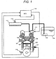
- FIG. 1 is a diagram showing an outline of a configuration of a cylinder injection type engine. A basic operation of the cylinder injection type engine will be described using FIG. 1 .
- a combustion chamber 104 is formed by a cylinder head 101, a cylinder block 102, and a piston 103 inserted into the cylinder block 102 and an intake pipe 105 and an exhaust pipe 106 are branched into two parts toward the combustion chamber 104 and are connected.
- An intake valve 107 is provided in an opening portion of the intake pipe 105
- an exhaust valve 108 is provided in an opening portion of the exhaust pipe 106, and the intake valve 107 and the exhaust valve 108 are operated to be opened and closed by a cam operation method.
- the piston 103 is connected to a crankshaft 115 via a connecting rod 114 and an engine speed can be detected by a crank angle sensor 116.
- a value of the rotation speed is sent to an engine control unit (ECU) 118.
- a starter motor not shown in the drawings is connected to the crankshaft 115 and at the time of starting an engine, the crankshaft 115 can be rotated by the starter motor and the engine can be started.
- a water temperature sensor 117 is provided in the cylinder block 102 and can detect a temperature of engine cooling water not shown in the drawings. The temperature of the engine cooling water is sent to the ECU 118.
- FIG. 1 describes only one cylinder
- a collector not shown in the drawings is provided at the upstream side of the intake pipe 105 to distribute air for each cylinder.
- An air flow sensor and a throttle valve not shown in the drawings are provided at the upstream side of the collector and an amount of air sucked into the combustion chamber 104 can be adjusted by an opening degree of the throttle valve.
- Fuel is stored in a fuel tank 109 and is sent to a high-pressure fuel pump 111 by a feed pump 110.
- the feed pump 110 boosts the fuel to about 0.3 MPa and sends the fuel to the high-pressure fuel pump 111.
- the fuel boosted by the high-pressure fuel pump 111 is sent to a common rail 112.
- the high-pressure fuel pump 111 boosts the fuel to about 30 MPa and sends the fuel to the common rail 112.
- a fuel pressure sensor 113 is provided in the common rail 112 to detect a fuel pressure. A value of the fuel pressure is sent to the ECU 118.
- FIG. 2 is a diagram showing a configuration of a cylinder center cross-section of a cylinder injection type engine.
- a fuel injection valve 119 is provided in an upper portion of the cylinder in an axial direction and in a center portion of the cylinder in a radial direction.
- a fluid injection valve 121 is provided in a side surface portion in the radial direction.
- An ignition plug 120 is provided in the vicinity of the exhaust pipe 106.
- the ECU 118 can monitor signals of sensors and can control operations of devices such as the fuel injection valve 119, the ignition plug 120, and the high-pressure fuel pump 111.
- a ROM of the ECU 118 setting values of various devices according to the engine speed, the water temperature, and the air-fuel ratio which are used generally are recorded as map data.
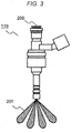
- FIG. 3 is a diagram showing an outline of the fuel injection valve according to this embodiment.
- the fuel is supplied from a fuel supply port 200 and is supplied to the inside of the fuel injection valve.
- the electromagnetic fuel injection valve 119 shown in FIG. 3 is normally of a closed electromagnetic drive type and when there is no energization, the fuel is sealed.
- the supplied fuel pressure is in a range of about 1 MPa to 50 MPa.
- fuel injection is started. If the fuel injection is started, energy given as the fuel pressure is converted into motion energy, reaches an empty fuel injection hole in a lower end portion of the fuel injection valve, and is injected.
- the injected fuel is atomized by the shearing force with atmosphere to form fuel sprays 201.
- FIG. 4 is an enlarged cross-sectional view of the lower end portion of the fuel injection valve that includes a seat member 202, a valve body 203, and the like.
- the seat member 202 includes a valve seat surface 204 and a plurality of fuel injection holes 205.
- the valve seat surface 204 and the valve body 203 axisymmetrically extend around a valve body center axis 206.
- the fuel passes through a gap between the seat member 202 and the valve body 203 and is injected from the injection hole 205.
- the fuel is injected in a direction of an injection hole axis 207 and is atomized by the shearing force with gas.
- a nozzle form of the fuel injection valve 119, a fuel pressure, and the like are set such that a Sauter average particle size of an injected fuel droplet is approximately 30 ⁇ m or less.
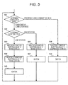
- FIG. 5 is a flowchart of injection control according to this embodiment.
- determination of a combustion mode shown by control S01 is first performed.
- the combustion mode is determined by an engine torque and a rotation speed by a combustion mode map shown in FIG. 6 .
- control S08 and the following control are performed in a normal stratified charge combustion mode.
- determination of the rotation speed is performed in control S02.
- control S03 and the following controls are performed and in the other case, control S06 and the following controls are performed in a normal homogeneous combustion mode.
- control S03 after performing injection from the fuel injection valve in the intake stroke, injection from the fluid injection valve is performed and in control S03, after performing the injection from the fluid injection valve in the intake stroke, ignition is performed by control S05 in the latter half of the compression stroke.
- FIG. 7 is a schematic diagram of current pulses to operate the fuel injection valve and the fluid injection valve in this embodiment.
- the fluid injection valve that is configured separately from the fuel injection valve and has a function of injecting a fluid is provided.
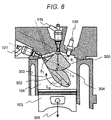
- FIG. 8 is a diagram showing the combustion chamber of the internal combustion engine according to this embodiment.
- the combustion chamber 104 is provided with the fluid injection valve 121 which is separated from the fuel injection valve 119 and serves as a stirring mechanism and driving of the fluid injection valve 121 is controlled by the ECU 118.
- the ECU 118 includes a central processing unit (CPU).
- the ECU 118 performs control such that the fuel is injected from the fuel injection valve 119 according to a command from the CPU (control unit) of the ECU 118 and then controls the fuel injection valve 119 and the fluid injection valve 121 such that the fluid is injected from the fluid injection valve 121 and the fuel injected from the fuel injection valve is stirred.
- CPU control unit
- the CPU (control unit) of the ECU 118 controls the fuel injection valve 119 by control S03 shown in FIG. 5 , injects the fuel into the combustion chamber 104, and forms a spray 300.
- penetration and injection timing may be set such that penetration LA of the spray 300 injected from the fuel injection valve does not adhere to a wall surface.
- the spray 300 is not flown by the tumble flow but drifts in the cylinder.
- the CPU (control unit) of the ECU 118 controls the fluid injection valve 121 by control S04 and causes the fluid to be injected into the combustion chamber 104.
- An injected fluid 302 stirs the spray 300 injected from the fuel injection valve and forms a homogeneous air-fuel mixture in the combustion chamber 104.
- the fluid injection valve is caused to be delayed compared with the fuel injection valve and injects the fluid, thereby stirring the fuel in the combustion chamber. As a result, even when the air flow in the cylinder is slow, the homogeneous air-fuel mixture can be formed. According to this embodiment, it is possible to form the homogeneous air-fuel mixture in homogeneous combustion when the engine rotates at a low speed.
- the CPU (control unit) of the ECU 118 controls the ignition plug 120 by control S05 shown in FIG. 5 , ignites the ignition plug 120 with spark ignition, and burns the air-fuel mixture in the combustion chamber 104.
- the internal combustion engine including the ignition plug is described as an example in this embodiment, an effect according to this embodiment can be similarly obtained also in a compression self-ignition type internal combustion engine not including the ignition plug.
- the fuel injection valve 119 is arranged on the upper portion of the internal combustion engine, so that the fuel can be injected over a wider range. By injecting the fuel over the wide range, a degree of homogeneity of the air-fuel mixture can be increased.
- the fuel injection valve 119 is disposed in the vicinity of the ignition plug, so that combustion stability at the time of the stratified charge combustion can be increased.
- a spray angle ⁇ 1 is preferably designed such that the fuel does not adhere to the cylinder wall surface in the intake stroke and a sufficient spray angle is obtained when the fuel is injected in the compression stroke.
- the fluid injection valve 121 is provided on a side surface and forms a longitudinal vortex 303 in the cylinder. By forming the longitudinal vortex, it is possible to suitably stir the spray 300 injected from the fuel injection valve 119. By maximizing a distance between the fluid injection valve 121 and the wall surface, an amount of fuel adhering to the wall surface can be reduced when the fluid injected from the fluid injection valve 121 is the fuel.
- the tumble flow forms the vortex in the longitudinal direction and the homogeneous air-fuel mixture is formed in the cylinder by the vortex.
- the tumble flow is weak and it is difficult to form the longitudinal vortex.
- the longitudinal vortex is formed by the fluid injection valve 121, so that the homogeneous air-fuel mixture obtained at the time of the high rotation can be formed.
- the fuel injection valve 119 is attached to the upper portion of the internal combustion engine and the fluid injection valve 121 is attached to the side surface of the internal combustion engine, so that the degree of homogeneity of the air-fuel mixture can be increased.
- an effect of the invention does not limit r the arrangement of the fuel injection valve and the arrangement of the ignition plug.
- the effect of the invention is achieved.
- at least one spray direction may be oriented to the ignition plug to increase combustion stability at the time of the stratified charge combustion.
- fuel injection timing is, for example, 60 deg. That is, the CPU (control unit) of the ECU 118 performs control such that the fuel is injected from the fuel injection valve 119, in a state in which the piston descends, and then controls the fuel injection valve 119 and the fluid injection valve 121 such that the fluid is injected from the fluid injection valve 121 and the fuel injected from the fuel injection valve is stirred.
- the piston descends as shown by a piston movement direction 305, so that the fluid flows downward into the cylinder, thereby assisting the flow of the fluid 302.
- the longitudinal vortex 303 in the cylinder is strengthened and the spray 300 injected from the fuel injection valve 119 can be suitably stirred.
- an injection hole axis of the fuel injection valve 119 and an injection hole axis of the fluid injection valve 121 preferably intersect each other at the side of the ignition plug rather than the piston in a state in which the piston is at a bottom dead center. That is, as shown in FIG. 8 , an intersection point 304 may exist at the side of the ignition plug rather than the piston.
- the intersection point may exist in a range of the angle ⁇ 2 .
- the fluid 302 injected from the fluid injection valve collides with the spray 300. The collision of the fluid 302 with the spray 300 causes an exchange of momentum, so that the fuel is stirred more suitably in the cylinder. From the above, the homogeneous air-fuel mixture can be suitably formed.
- FIG. 9 is a schematic diagram showing a general relation between an injection speed and penetration.
- V A ⁇ V B between injection speeds V A and V B
- penetrations has a relation of L A ⁇ L B . Therefore, when the injection speed is large, the penetration increases.
- FIG. 10 is a schematic diagram showing a relation between the motion energy of the fluid and the injection speed. When there is a relation of V A ⁇ V B between the injection speeds V A and V B , motion energies of the fluid has a relation of E A ⁇ E B .
- the motion energy of the fluid 302 (in this embodiment, the fuel spray 302 for stirring) injected from the fluid injection valve 121 (in this embodiment, the fuel injection valve for stirring) is larger than the motion energy of the spray 300 injected from the fuel injection valve 119, the fluid flows downward into the cylinder, and the longitudinal vortex 303 is formed, so that it is possible to stir the spray 300 injected from the fuel injection valve 119 and form the homogeneous air-fuel mixture in the cylinder.
- FIG. 11 is a flowchart of the injection control according to this embodiment and is a diagram similar to FIG. 5 .
- control S13 after performing injection from the fuel injection valve 119 in the intake stroke, the fluid is injected from the fuel injection valve for stirring by control S14.
- the injected spray 302 stirs the spray 300 injected from the fuel injection valve 119 and forms a homogeneous air-fuel mixture in the combustion chamber 104.
- control S12 When the high rotation is determined by control S12, control is preferably performed such that the fuel is injected from the fuel injection valve for stirring by control S16. This is because the tumble flow is strengthened when the engine rotates at a high speed and a spray with long penetration is required to cause the spray not to be flown by the tumble flow. For this reason, at the time of the high rotation, the fuel is injected from the fuel injection valve for stirring with long penetration, so that the homogeneous air-fuel mixture can be formed.
- FIG. 12 shows a relation between current pulses to operate the fuel injection valve 119 and the fuel injection valve 121 for stirring and a piston position.
- Time T 1 is injection start time of the fuel injection valve 119 and time T 2 is injection start time of the fuel injection valve 121.
- the injection timing of the fuel injection valve 121 is, for example, -20 deg to +20 deg from the bottom dead center.
- the length of the penetration of the fuel injection valve 121 is preferably optimized such that the degree of homogeneity increases, in a range in which the fuel does not adhere to the piston.
- the penetration of the fuel spray 302 is set to be shortened, so that adhesion to the piston and the cylinder wall surface is reduced.
- penetration L B is set as a distance from the fuel injection valve to the piston at a certain crank angle ⁇ , the degree of homogeneity of the air-fuel mixture can be increased while the adhesion is suitably suppressed.
- FIG. 13 is an enlarged view of the vicinity of the injection hole 205 in the same cross-section as FIG. 4 .
- the valve body 206 and the valve seat surface 204 contact at a ground point 400 when the valve is closed and are separated by a stroke amount St when the valve is opened.
- the fuel flows in a radial inward direction toward the center axis 206 of the valve body, passes through a path of a flow line 401, flows into an injection hole 402 from an injection hole inlet 404, and is injected from an injection hole outlet 405.
- a part of the fuel flows into a suck chamber 403 once and then flows into the injection hole 402.
- An amount of flowing fuel is controlled by the stroke amount St and a flow rate when the St is large is larger than a flow rate when St is small. Since a fluid speed increases when the flow rate is large, the penetration can be set by the stroke amount St.
- the penetration can be set also by a ratio of a length L of the injection hole and an outlet diameter D; L/D.
- L/D a ratio of a length L of the injection hole and an outlet diameter D
- the fluid injection valve 121 is a fuel injection valve for stirring separated from the fuel injection valve 119 and the injection hole formed in the fuel injection valve for stirring has L/D larger than that in the fuel injection valve 119, so that it is possible to stir the spray 300 injected from the fuel injection valve 119 and form a homogeneous air-fuel mixture in the cylinder.
- the penetration can be changed also in multi-stage injection using short pulse injection or short pulse injection.
- short pulse injection because the penetration becomes short, the amount of adhesion to the wall surface can be further reduced.
- short pulse injection because an injection amount per pulse decreases, a necessary amount of fuel is preferably injected by the multi-stage injection.
- the present invention it is possible to increase the combustion speed while increasing the degree of homogeneity of the air-fuel mixture.
- the combustion can be performed in a short period and a constant volume degree of the combustion process can be increased.
- By increasing the constant volume degree heat efficiency is improved and fuel consumption efficiency is improved.
- turbulent motion energy representing the magnitude of the turbulence of the flow also increases.
- a propagation speed of a flame correlates with the turbulent motion energy and when the turbulence motion energy increases, an effect of improving the combustion speed can be expected.
- the turbulence motion energy in the cylinder increases and the combustion speed can be increased while the degree of homogeneity of the air-fuel mixture is increased.
- This embodiment functions suitably when the engine speed is low and the air flow in the cylinder is slow. Therefore, it can be used at the time of starting the engine, for example.
- a warm-up operation may be performed for the purpose of warming up a catalyst.
- control for raising the exhaust temperature is performed, for example, by retarding the ignition timing, so that the warm-up of the catalyst can be performed suitably while the degree of homogeneity of the air-fuel mixture is increased.
- the CPU (control unit) of the ECU 118 controls the fluid injection valve such that the fuel injected from the fuel injection valve is stirred in a state in which the piston of the internal combustion engine is at the vicinity of the bottom dead center after performing control such that injection is performed from the fuel injection valve in one stroke of the piston. If the internal combustion engine enters the warming-up operation, the CPU switches the control into control for retarding the ignition timing. As a result, the warm-up of the catalyst can be suitably performed while the degree of homogeneity of the air-fuel mixture is increased.
- the effect of the present invention is not limited to the case where the rotation speed is low and the same effect can be obtained when the air flow in the cylinder is slow. For example, even when the intake valve is opened in the vicinity of the top dead center and the negative pressure in the cylinder is insufficient, the same effect is obtained.
- a fuel injection valve according to a second embodiment of the present invention will be described below using FIG. 14 .
- a fuel injection valve 121 for stirring that is separated from a fuel injection valve 119 is provided as an air-fuel mixture stirring mechanism.
- the other configuration is the same as that in the first embodiment.
- a high-pressure fuel pump 310 separated from a high-pressure fuel pump 111 is provided and fuel is sent from a fuel tank 109 to the high-pressure fuel pump 310 by a feed pump 110.
- the fuel boosted by the high-pressure fuel pump 310 is sent to a common rail 311.
- a fuel pressure sensor 312 is provided in the common rail 311 to detect a fuel pressure.
- penetration of a spray injected from the fuel injection valve 121 for stirring can be lengthened by applying a higher fuel pressure to the fuel injection valve 121 for stirring as compared with the fuel injection valve 119. That is, the fluid injection valve 121 for stirring is a fuel injection valve for stirring separated from the fuel injection valve 119.
- the fuel pressure applied to the fuel injection valve 121 for stirring is configured to be larger with respect to the fuel injection valve 119, so that it is possible to stir a spray 300 injected from the fuel injection valve 119 and form a homogeneous air-fuel mixture in a cylinder.
- a fuel injection valve according to a third embodiment of the present invention will be described below using FIG. 15 .
- a gas injection valve 501 for stirring separated from a fuel injection valve 119, a common rail 500 for injecting gas, a tank 501 for storing the gas, a pressure adjustment valve 503 for adjusting a flow rate of the gas, and a flowmeter 504 are provided as an air-fuel mixture stirring mechanism.
- the other configuration is the same as that in the first embodiment.
- Gas fuel such as CNG is injected from the gas injection valve 501.
- a control method is the same as that in the first embodiment.
- air may be injected from the gas injection valve 501.
- a compressor instead of the tank for storing the gas may be provided and air may be supplied from an intake port.
- a part of recirculated exhaust gas may be injected from the gas injection valve 501. That is, a CPU (control unit) of an ECU 118 performs control such that the air or the recirculated exhaust is injected from the gas injection valve 501 for stirring and the fuel injected from the fuel injection valve 119 is stirred. In this case, similar to the air, the recirculated exhaust gas is boosted by the compressor and is injected from the gas injection valve 501.
- the CPU control unit
- the ECU 118 performs control such that the fuel is injected from the fuel injection valve in a state in which the piston is at 40 deg to 60 deg and then injection is preformed from the fluid injection valve in a state in which the piston is at 60 deg to 80 deg and the fuel is mixed with the gas early and is vaporized.
- adhesion of the fuel to a wall surface can be suitably reduced.
Landscapes
- Engineering & Computer Science (AREA)
- Chemical & Material Sciences (AREA)
- Combustion & Propulsion (AREA)
- Mechanical Engineering (AREA)
- General Engineering & Computer Science (AREA)
- Signal Processing (AREA)
- Oil, Petroleum & Natural Gas (AREA)
- Fuel-Injection Apparatus (AREA)
- Electrical Control Of Air Or Fuel Supplied To Internal-Combustion Engine (AREA)
- Combustion Methods Of Internal-Combustion Engines (AREA)
- Exhaust-Gas Circulating Devices (AREA)
Abstract
Description
- The present invention relates to a fuel injection valve control device that is used in an internal combustion engine such as a gasoline engine.
- Recently, demands for improvement in fuel consumption of gasoline engines in vehicles have increased and a cylinder injection type engine that directly injects fuel into a combustion chamber, ignites an air-fuel mixture of the injected fuel and sucked air with an ignition plug, and explodes the air-fuel mixture has been widely used as an engine excellent in the fuel consumption. However, in the cylinder injection type engine, because a distance from an injection point to a wall surface is short, the fuel is likely to adhere to the inside of the combustion chamber and suppression of a particle matter (PM) generated by incomplete combustion of the fuel adhered to the wall surface having a low temperature becomes a problem. To solve this problem and develop a direct injection engine with low fuel consumption and low exhaust gas, optimization of combustion in the combustion chamber is necessary.
- There are various operation situations such as a high-load operation, a low-load operation, and cold starting in operations of the vehicles.
- Therefore, in the cylinder injection type engine, to perform optimum combustion depending on the operation situations, homogeneous combustion for forming a homogeneous air-fuel mixture in a cylinder and burning the air-fuel mixture and stratified charge combustion for forming a thick air-fuel mixture around an ignition plug are used separately.
- To achieve both the homogeneous combustion and the stratified charge combustion, a method has been suggested in which a plurality of fuel injection valves for directly injecting the fuel into the combustion chamber is provided for each cylinder. For example,
PTL 1 describes technology in which two fuel injection valves are provided for each cylinder, a first fuel injection valve is used at the time of the homogeneous combustion, and a second fuel injection valve is used at the time of the stratified charge combustion.PTL 1 discloses technology in which a fuel injection valve with a large static flow is used at the time of the homogeneous combustion and a fuel injection valve with a small static flow and short penetration is used at the time of the stratified charge combustion. - PTL 1:
JP 2010-196506 A - In the cylinder injection type engine, a homogeneous combustion mode in which, when a high-load operation is performed, fuel is injected in an intake stroke, a homogeneous air-fuel mixture is formed in the cylinder, and the air-fuel mixture is burned and a stratified charge combustion mode in which, when a load is relatively low, the fuel is injected at the latter stage of a compression stroke, a thick air-fuel mixture is stratified around an ignition plug and the air-fuel mixture is burned are known.
- In the stratified charge combustion mode, burning is performed in a state in which an air-fuel ratio of the entire cylinder is larger than a theoretical air-fuel ratio. Therefore, to perform stable ignition, it is necessary to arrange fuel having an appropriate concentration around the ignition plug. For this reason, a spray guide system for arranging the fuel injection valve and the ignition plug in proximity to a center portion of an upper portion of the combustion chamber, injecting the fuel from the fuel injection valve to the vicinity of an electrode of the ignition plug, and igniting the fuel with the ignition plug is devised. In this system, because a distance from an injection point to the ignition plug is short, a required travel distance of the spray is very small. For this reason, a fuel injection valve having small penetration force (penetration) of the spray is required.
- On the other hand, in the homogeneous combustion mode, fuel injection is performed in a state in which an intake valve is opened, the fuel is mixed by a gas flow (tumble flow) flowing from an intake port to the inside of the combustion chamber, and a homogeneous air-fuel mixture is formed. At this time, if the penetration force of the spray is not sufficient, the spray is caused to flow to the side of the wall surface in the cylinder by the tumble flow, and the homogeneous air-fuel mixture cannot be formed. For this reason, a fuel injection valve having large penetration force (long penetration) is required.
- To solve such conflicting demands for the fuel injection valve, a method of providing a plurality of fuel injection valves for directly injecting the fuel into the combustion chamber for each cylinder is suggested.
- In the technology disclosed in
PTL 1, the two fuel injection valves are provided for each cylinder, the first fuel injection valve with the long penetration is used at the time of the homogeneous combustion, and the second fuel injection valve with the short penetration is used at the time of the stratified charge combustion, so that it is possible to form an optimum spray in each mode of the homogeneous combustion mode and the stratified charge combustion mode and achieve high performance. - In the intake stroke, the strength of the tumble flow changes depending on an engine speed. When the engine rotates at a high speed, a movement speed of a piston is high and a flow rate of gas flowing into the cylinder per unit time increases, so that the tumble flow becomes strong. For this reason, a spray with the long penetration is required to prevent the spray from being flown by the tumble flow.
- On the other hand, when the engine rotates at a low speed, the movement speed of the piston is low and the flow rate of the gas flowing into the cylinder per unit time decreases, so that the tumble flow becomes weak. For this reason, mixing force by the tumble flow decreases and it is difficult to form a homogeneous air-fuel mixture in the cylinder.
- In the technology disclosed in
PTL 1, when the homogeneous combustion mode is set at the time of the low rotation and high load, the fuel injection valve with the long penetration is used in a state in which the tumble flow is weak and the mixing force is small. For this reason, adhesion of the fuel to the wall surface may increase and homogeneity may be deteriorated. - The present invention has been made in view of the above problem and an object thereof is to provide a fuel injection valve capable of forming a homogeneous air-fuel mixture in homogeneous combustion at a low engine speed and a control device thereof.
- To solve the above problem, a control device of a fuel injection valve according to the present invention is provided with a fluid injection valve that is configured separately from the fuel injection valve and has a function of injecting a fluid and includes a control unit that performs control such that fuel is injected from the fuel injection valve and then controls the fluid injection valve such that the fluid is injected from the fluid injection valve and the fuel injected from the fuel injection valve is stirred.
- According to the present invention, a homogeneous air-fuel mixture can be formed in homogeneous combustion at a low engine speed. Other configurations, functions, and effects of the present invention will be described in detail in the following embodiments.
-
- [
FIG. 1] FIG. 1 is a diagram showing an outline of a configuration of an internal combustion engine according to the present invention. - [
FIG. 2] FIG. 2 is a diagram showing a configuration of a cylinder center cross-section of an internal combustion engine according to a first embodiment of the present invention. - [
FIG. 3] FIG. 3 is a diagram showing a fuel injection valve according to the first embodiment of the present invention. - [
FIG. 4] FIG. 4 is an enlarged cross-sectional view of a lower end portion of the fuel injection valve according to the first embodiment of the present invention. - [
FIG. 5] FIG. 5 is a flowchart of injection control according to the first embodiment of the present invention. - [
FIG. 6] FIG. 6 is a combustion mode map according to the first embodiment of the present invention. - [
FIG. 7] FIG. 7 is a schematic diagram of current pulses to operate a fuel injection valve and a fluid injection valve according to the first embodiment of the present invention. - [
FIG. 8] FIG. 8 is a diagram showing a combustion chamber of the internal combustion engine according to the first embodiment of the present invention. - [
FIG. 9] FIG. 9 is a diagram showing a relation of an injection speed and penetration of the fuel injection valve according to the present invention. - [
FIG. 10] FIG. 10 is a diagram showing a relation of a total sum of in-cylinder motion energies of the internal combustion engine and an injection speed according to the present invention. - [
FIG. 11] FIG. 11 is a flowchart of injection control using a fuel injection valve for stirring according to the first embodiment of the present invention. - [
FIG. 12] FIG. 12 is a diagram showing a current pulse to operate the fuel injection valve according to the first embodiment of the present invention. - [
FIG. 13] FIG. 13 is an enlarged cross-sectional view of the vicinity of a tip of a valve body of the fuel injection valve according to the first embodiment of the present invention. - [
FIG. 14] FIG. 14 is a diagram showing a configuration of a cylinder center cross-section of the internal combustion engine according to the first embodiment of the present invention. - [
FIG. 15] FIG. 15 is a diagram showing a configuration of a cylinder center cross-section of an internal combustion engine according to a second embodiment of the present invention. - Hereinafter, embodiments of the present invention will be described.
- A control device of a fuel injection valve according to a first embodiment of the present invention will be described below using
FIGS. 1 and2 . -
FIG. 1 is a diagram showing an outline of a configuration of a cylinder injection type engine. A basic operation of the cylinder injection type engine will be described usingFIG. 1 . InFIG. 1 , acombustion chamber 104 is formed by acylinder head 101, acylinder block 102, and apiston 103 inserted into thecylinder block 102 and anintake pipe 105 and anexhaust pipe 106 are branched into two parts toward thecombustion chamber 104 and are connected. An intake valve 107 is provided in an opening portion of theintake pipe 105, anexhaust valve 108 is provided in an opening portion of theexhaust pipe 106, and the intake valve 107 and theexhaust valve 108 are operated to be opened and closed by a cam operation method. - The
piston 103 is connected to acrankshaft 115 via a connectingrod 114 and an engine speed can be detected by acrank angle sensor 116. A value of the rotation speed is sent to an engine control unit (ECU) 118. A starter motor not shown in the drawings is connected to thecrankshaft 115 and at the time of starting an engine, thecrankshaft 115 can be rotated by the starter motor and the engine can be started. Awater temperature sensor 117 is provided in thecylinder block 102 and can detect a temperature of engine cooling water not shown in the drawings. The temperature of the engine cooling water is sent to theECU 118. - Although
FIG. 1 describes only one cylinder, a collector not shown in the drawings is provided at the upstream side of theintake pipe 105 to distribute air for each cylinder. An air flow sensor and a throttle valve not shown in the drawings are provided at the upstream side of the collector and an amount of air sucked into thecombustion chamber 104 can be adjusted by an opening degree of the throttle valve. - Fuel is stored in a
fuel tank 109 and is sent to a high-pressure fuel pump 111 by afeed pump 110. Thefeed pump 110 boosts the fuel to about 0.3 MPa and sends the fuel to the high-pressure fuel pump 111. The fuel boosted by the high-pressure fuel pump 111 is sent to acommon rail 112. The high-pressure fuel pump 111 boosts the fuel to about 30 MPa and sends the fuel to thecommon rail 112. Afuel pressure sensor 113 is provided in thecommon rail 112 to detect a fuel pressure. A value of the fuel pressure is sent to theECU 118. -
FIG. 2 is a diagram showing a configuration of a cylinder center cross-section of a cylinder injection type engine. Afuel injection valve 119 is provided in an upper portion of the cylinder in an axial direction and in a center portion of the cylinder in a radial direction. In addition, afluid injection valve 121 is provided in a side surface portion in the radial direction. Anignition plug 120 is provided in the vicinity of theexhaust pipe 106. TheECU 118 can monitor signals of sensors and can control operations of devices such as thefuel injection valve 119, theignition plug 120, and the high-pressure fuel pump 111. In a ROM of theECU 118, setting values of various devices according to the engine speed, the water temperature, and the air-fuel ratio which are used generally are recorded as map data. -
FIG. 3 is a diagram showing an outline of the fuel injection valve according to this embodiment. The fuel is supplied from afuel supply port 200 and is supplied to the inside of the fuel injection valve. The electromagneticfuel injection valve 119 shown inFIG. 3 is normally of a closed electromagnetic drive type and when there is no energization, the fuel is sealed. At this time, in the fuel injection valve for cylinder injection, the supplied fuel pressure is in a range of about 1 MPa to 50 MPa. In the case of an energization state, fuel injection is started. If the fuel injection is started, energy given as the fuel pressure is converted into motion energy, reaches an empty fuel injection hole in a lower end portion of the fuel injection valve, and is injected. The injected fuel is atomized by the shearing force with atmosphere to formfuel sprays 201. - Next, a detailed shape of the fuel injection valve will be described using
FIG. 4. FIG. 4 is an enlarged cross-sectional view of the lower end portion of the fuel injection valve that includes aseat member 202, avalve body 203, and the like. Theseat member 202 includes avalve seat surface 204 and a plurality of fuel injection holes 205. Thevalve seat surface 204 and thevalve body 203 axisymmetrically extend around a valvebody center axis 206. The fuel passes through a gap between theseat member 202 and thevalve body 203 and is injected from theinjection hole 205. The fuel is injected in a direction of aninjection hole axis 207 and is atomized by the shearing force with gas. In the fuel injection valve for the cylinder injection type engine, a nozzle form of thefuel injection valve 119, a fuel pressure, and the like are set such that a Sauter average particle size of an injected fuel droplet is approximately 30 µm or less. - Next, a control method of homogeneous combustion using the fuel injection valve according to this embodiment will be described using
FIG. 5. FIG. 5 is a flowchart of injection control according to this embodiment. When the fuel is injected, determination of a combustion mode shown by control S01 is first performed. The combustion mode is determined by an engine torque and a rotation speed by a combustion mode map shown inFIG. 6 . When the combustion mode is determined to be a stratified charge combustion mode in control S01, control S08 and the following control are performed in a normal stratified charge combustion mode. When the combustion mode is determined to be a homogeneous combustion mode, determination of the rotation speed is performed in control S02. Here, when the rotation speed is a predetermined rotation speed or less, control S03 and the following controls are performed and in the other case, control S06 and the following controls are performed in a normal homogeneous combustion mode. - In control S03, after performing injection from the fuel injection valve in the intake stroke, injection from the fluid injection valve is performed and in control S03, after performing the injection from the fluid injection valve in the intake stroke, ignition is performed by control S05 in the latter half of the compression stroke.
-
FIG. 7 is a schematic diagram of current pulses to operate the fuel injection valve and the fluid injection valve in this embodiment. In the internal combustion engine according to this embodiment, the fluid injection valve that is configured separately from the fuel injection valve and has a function of injecting a fluid is provided. - Next, a form in the combustion chamber will be described.
FIG. 8 is a diagram showing the combustion chamber of the internal combustion engine according to this embodiment. Thecombustion chamber 104 is provided with thefluid injection valve 121 which is separated from thefuel injection valve 119 and serves as a stirring mechanism and driving of thefluid injection valve 121 is controlled by theECU 118. More specifically, theECU 118 includes a central processing unit (CPU). TheECU 118 performs control such that the fuel is injected from thefuel injection valve 119 according to a command from the CPU (control unit) of theECU 118 and then controls thefuel injection valve 119 and thefluid injection valve 121 such that the fluid is injected from thefluid injection valve 121 and the fuel injected from the fuel injection valve is stirred. - The CPU (control unit) of the
ECU 118 controls thefuel injection valve 119 by control S03 shown inFIG. 5 , injects the fuel into thecombustion chamber 104, and forms aspray 300. At this time, penetration and injection timing may be set such that penetration LA of thespray 300 injected from the fuel injection valve does not adhere to a wall surface. At the time of low rotation, because a tumble flow in the cylinder is weak, thespray 300 is not flown by the tumble flow but drifts in the cylinder. - Next, the CPU (control unit) of the
ECU 118 controls thefluid injection valve 121 by control S04 and causes the fluid to be injected into thecombustion chamber 104. An injectedfluid 302 stirs thespray 300 injected from the fuel injection valve and forms a homogeneous air-fuel mixture in thecombustion chamber 104. Generally, when the engine rotates at a low speed, the air flow in the cylinder is insufficient and it is difficult to form a homogeneous air-fuel mixture. In this embodiment, the fluid injection valve is caused to be delayed compared with the fuel injection valve and injects the fluid, thereby stirring the fuel in the combustion chamber. As a result, even when the air flow in the cylinder is slow, the homogeneous air-fuel mixture can be formed. According to this embodiment, it is possible to form the homogeneous air-fuel mixture in homogeneous combustion when the engine rotates at a low speed. - The CPU (control unit) of the
ECU 118 controls theignition plug 120 by control S05 shown inFIG. 5 , ignites theignition plug 120 with spark ignition, and burns the air-fuel mixture in thecombustion chamber 104. Although the internal combustion engine including the ignition plug is described as an example in this embodiment, an effect according to this embodiment can be similarly obtained also in a compression self-ignition type internal combustion engine not including the ignition plug. - Although this embodiment does not limit the position of the fuel injection valve, the
fuel injection valve 119 is arranged on the upper portion of the internal combustion engine, so that the fuel can be injected over a wider range. By injecting the fuel over the wide range, a degree of homogeneity of the air-fuel mixture can be increased. In addition, thefuel injection valve 119 is disposed in the vicinity of the ignition plug, so that combustion stability at the time of the stratified charge combustion can be increased. - Generally, in the case where the stratified charge combustion is performed by a spray guide system, if the injection is performed in the compression stroke, a spray angle decreases. When the fuel injection valve used for the stratified charge combustion is used in the intake stroke, the spray angle increases. Therefore, a spray angle θ1 is preferably designed such that the fuel does not adhere to the cylinder wall surface in the intake stroke and a sufficient spray angle is obtained when the fuel is injected in the compression stroke.
- On the other hand, the
fluid injection valve 121 is provided on a side surface and forms alongitudinal vortex 303 in the cylinder. By forming the longitudinal vortex, it is possible to suitably stir thespray 300 injected from thefuel injection valve 119. By maximizing a distance between thefluid injection valve 121 and the wall surface, an amount of fuel adhering to the wall surface can be reduced when the fluid injected from thefluid injection valve 121 is the fuel. - In the homogeneous combustion at the high rotation, the tumble flow forms the vortex in the longitudinal direction and the homogeneous air-fuel mixture is formed in the cylinder by the vortex. At the time of the low rotation, the tumble flow is weak and it is difficult to form the longitudinal vortex. However, the longitudinal vortex is formed by the
fluid injection valve 121, so that the homogeneous air-fuel mixture obtained at the time of the high rotation can be formed. - That is, the
fuel injection valve 119 is attached to the upper portion of the internal combustion engine and thefluid injection valve 121 is attached to the side surface of the internal combustion engine, so that the degree of homogeneity of the air-fuel mixture can be increased. - However, an effect of the invention does not limit r the arrangement of the fuel injection valve and the arrangement of the ignition plug. For example, even when the arrangement of the
fuel injection valve 119 and thefluid injection valve 121 is reversed, the effect of the invention is achieved. However, in the case where the fuel injection valve is arranged on the side portion and the ignition plug is arranged on the center, at least one spray direction may be oriented to the ignition plug to increase combustion stability at the time of the stratified charge combustion. - In this embodiment, when a top dead center is set to 0 deg, fuel injection timing is, for example, 60 deg. That is, the CPU (control unit) of the
ECU 118 performs control such that the fuel is injected from thefuel injection valve 119, in a state in which the piston descends, and then controls thefuel injection valve 119 and thefluid injection valve 121 such that the fluid is injected from thefluid injection valve 121 and the fuel injected from the fuel injection valve is stirred. The piston descends as shown by apiston movement direction 305, so that the fluid flows downward into the cylinder, thereby assisting the flow of thefluid 302. As a result, thelongitudinal vortex 303 in the cylinder is strengthened and thespray 300 injected from thefuel injection valve 119 can be suitably stirred. - In addition, an injection hole axis of the
fuel injection valve 119 and an injection hole axis of thefluid injection valve 121 preferably intersect each other at the side of the ignition plug rather than the piston in a state in which the piston is at a bottom dead center. That is, as shown inFIG. 8 , anintersection point 304 may exist at the side of the ignition plug rather than the piston. In addition, when the fluid 302 has an angle θ2, the intersection point may exist in a range of the angle θ2. When there is the intersection point, the fluid 302 injected from the fluid injection valve collides with thespray 300. The collision of the fluid 302 with thespray 300 causes an exchange of momentum, so that the fuel is stirred more suitably in the cylinder. From the above, the homogeneous air-fuel mixture can be suitably formed. - The fluid injection valve described above may be a fuel injection valve for stirring separated from the fuel injection valve and the CPU (control unit) of the
ECU 118 may perform control such that penetration of the spray from the fuel injection valve for stirring is longer than penetration of the spray from the fuel injection valve. Thereby, the same effect of the invention is obtained. The principle thereof will be described below.FIG. 9 is a schematic diagram showing a general relation between an injection speed and penetration. When there is a relation of VA < VB between injection speeds VA and VB, penetrations has a relation of LA < LB. Therefore, when the injection speed is large, the penetration increases. Next,FIG. 10 is a schematic diagram showing a relation between the motion energy of the fluid and the injection speed. When there is a relation of VA < VB between the injection speeds VA and VB, motion energies of the fluid has a relation of EA < EB. - In
FIG. 8 , regarding the motion energy of thespray 300 injected from thefuel injection valve 119, the motion energy of the fluid 302 (in this embodiment, thefuel spray 302 for stirring) injected from the fluid injection valve 121 (in this embodiment, the fuel injection valve for stirring) is larger than the motion energy of thespray 300 injected from thefuel injection valve 119, the fluid flows downward into the cylinder, and thelongitudinal vortex 303 is formed, so that it is possible to stir thespray 300 injected from thefuel injection valve 119 and form the homogeneous air-fuel mixture in the cylinder. - Next, a control method of the homogeneous combustion using the fuel injection valve for stirring according to this embodiment will be described using
FIG. 10 .FIG. 11 is a flowchart of the injection control according to this embodiment and is a diagram similar toFIG. 5 . In control S13, after performing injection from thefuel injection valve 119 in the intake stroke, the fluid is injected from the fuel injection valve for stirring by control S14. The injectedspray 302 stirs thespray 300 injected from thefuel injection valve 119 and forms a homogeneous air-fuel mixture in thecombustion chamber 104. - When the high rotation is determined by control S12, control is preferably performed such that the fuel is injected from the fuel injection valve for stirring by control S16. This is because the tumble flow is strengthened when the engine rotates at a high speed and a spray with long penetration is required to cause the spray not to be flown by the tumble flow. For this reason, at the time of the high rotation, the fuel is injected from the fuel injection valve for stirring with long penetration, so that the homogeneous air-fuel mixture can be formed.
-
FIG. 12 shows a relation between current pulses to operate thefuel injection valve 119 and thefuel injection valve 121 for stirring and a piston position. Time T1 is injection start time of thefuel injection valve 119 and time T2 is injection start time of thefuel injection valve 121. By performing control such that the time T2 inFIG. 11 is at the vicinity of the bottom dead center of the piston, fuel adhesion to the wall surface can be reduced. In this embodiment, the injection timing of thefuel injection valve 121 is, for example, -20 deg to +20 deg from the bottom dead center. By the above control, it is possible to achieve both reduction of an amount of fuel adhered to the wall surface and strengthening of the air flow in the cylinder. The injection timings of the time T1 and the time T2 are not limited to the intake stroke. However, to sufficiently perform mixing and vaporization, mixing and vaporization are preferably performed in the intake stroke while the piston descends. - In addition, the length of the penetration of the
fuel injection valve 121 is preferably optimized such that the degree of homogeneity increases, in a range in which the fuel does not adhere to the piston. When the engine speed is low, the air flow in thecombustion chamber 104 is slow and the fuel is likely to adhere to the combustion chamber wall surface or the piston. InFIG. 8 , the penetration of thefuel spray 302 is set to be shortened, so that adhesion to the piston and the cylinder wall surface is reduced. For example, if penetration LB is set as a distance from the fuel injection valve to the piston at a certain crank angle θ, the degree of homogeneity of the air-fuel mixture can be increased while the adhesion is suitably suppressed. - Next, a method of setting the length of the penetration will be described.
FIG. 13 is an enlarged view of the vicinity of theinjection hole 205 in the same cross-section asFIG. 4 . Thevalve body 206 and thevalve seat surface 204 contact at aground point 400 when the valve is closed and are separated by a stroke amount St when the valve is opened. The fuel flows in a radial inward direction toward thecenter axis 206 of the valve body, passes through a path of aflow line 401, flows into aninjection hole 402 from aninjection hole inlet 404, and is injected from aninjection hole outlet 405. A part of the fuel flows into asuck chamber 403 once and then flows into theinjection hole 402. An amount of flowing fuel is controlled by the stroke amount St and a flow rate when the St is large is larger than a flow rate when St is small. Since a fluid speed increases when the flow rate is large, the penetration can be set by the stroke amount St. - The penetration can be set also by a ratio of a length L of the injection hole and an outlet diameter D; L/D. Generally, when L/D is large, the injection speed increases and the penetration becomes longer. For this reason, the
fluid injection valve 121 is a fuel injection valve for stirring separated from thefuel injection valve 119 and the injection hole formed in the fuel injection valve for stirring has L/D larger than that in thefuel injection valve 119, so that it is possible to stir thespray 300 injected from thefuel injection valve 119 and form a homogeneous air-fuel mixture in the cylinder. - In addition, the penetration can be changed also in multi-stage injection using short pulse injection or short pulse injection. In the short pulse injection, because the penetration becomes short, the amount of adhesion to the wall surface can be further reduced. On the other hand, in the short pulse injection, because an injection amount per pulse decreases, a necessary amount of fuel is preferably injected by the multi-stage injection.
- By using the present invention, it is possible to increase the combustion speed while increasing the degree of homogeneity of the air-fuel mixture. By improving the combustion speed, the combustion can be performed in a short period and a constant volume degree of the combustion process can be increased. By increasing the constant volume degree, heat efficiency is improved and fuel consumption efficiency is improved.
- When the motion energy representing the magnitude of the average motion of the flow increases, turbulent motion energy representing the magnitude of the turbulence of the flow also increases. A propagation speed of a flame correlates with the turbulent motion energy and when the turbulence motion energy increases, an effect of improving the combustion speed can be expected.
- That is, by performing control such that the fuel is injected from the fuel injection valve and then controlling the fluid injection valve such that the fluid is injected from the fluid injection valve and the fuel injected from the fluid injection valve is stirred, the turbulence motion energy in the cylinder increases and the combustion speed can be increased while the degree of homogeneity of the air-fuel mixture is increased.
- This embodiment functions suitably when the engine speed is low and the air flow in the cylinder is slow. Therefore, it can be used at the time of starting the engine, for example. At the time of starting the engine, a warm-up operation may be performed for the purpose of warming up a catalyst. When the engine speed increases and a mode becomes a warm-up operation mode, control for raising the exhaust temperature is performed, for example, by retarding the ignition timing, so that the warm-up of the catalyst can be performed suitably while the degree of homogeneity of the air-fuel mixture is increased.
- That is, the CPU (control unit) of the
ECU 118 controls the fluid injection valve such that the fuel injected from the fuel injection valve is stirred in a state in which the piston of the internal combustion engine is at the vicinity of the bottom dead center after performing control such that injection is performed from the fuel injection valve in one stroke of the piston. If the internal combustion engine enters the warming-up operation, the CPU switches the control into control for retarding the ignition timing. As a result, the warm-up of the catalyst can be suitably performed while the degree of homogeneity of the air-fuel mixture is increased. - The effect of the present invention is not limited to the case where the rotation speed is low and the same effect can be obtained when the air flow in the cylinder is slow. For example, even when the intake valve is opened in the vicinity of the top dead center and the negative pressure in the cylinder is insufficient, the same effect is obtained.
- A fuel injection valve according to a second embodiment of the present invention will be described below using
FIG. 14 . - In the second embodiment shown in
FIG. 14 , afuel injection valve 121 for stirring that is separated from afuel injection valve 119 is provided as an air-fuel mixture stirring mechanism. The other configuration is the same as that in the first embodiment. - In the second embodiment shown in
FIG. 14 , a high-pressure fuel pump 310 separated from a high-pressure fuel pump 111 is provided and fuel is sent from afuel tank 109 to the high-pressure fuel pump 310 by afeed pump 110. The fuel boosted by the high-pressure fuel pump 310 is sent to acommon rail 311. Afuel pressure sensor 312 is provided in thecommon rail 311 to detect a fuel pressure. At this time, penetration of a spray injected from thefuel injection valve 121 for stirring can be lengthened by applying a higher fuel pressure to thefuel injection valve 121 for stirring as compared with thefuel injection valve 119. That is, thefluid injection valve 121 for stirring is a fuel injection valve for stirring separated from thefuel injection valve 119. The fuel pressure applied to thefuel injection valve 121 for stirring is configured to be larger with respect to thefuel injection valve 119, so that it is possible to stir aspray 300 injected from thefuel injection valve 119 and form a homogeneous air-fuel mixture in a cylinder. - A fuel injection valve according to a third embodiment of the present invention will be described below using
FIG. 15 . In the third embodiment shown inFIG. 15 , agas injection valve 501 for stirring separated from afuel injection valve 119, acommon rail 500 for injecting gas, atank 501 for storing the gas, apressure adjustment valve 503 for adjusting a flow rate of the gas, and aflowmeter 504 are provided as an air-fuel mixture stirring mechanism. The other configuration is the same as that in the first embodiment. - Gas fuel such as CNG is injected from the
gas injection valve 501. A control method is the same as that in the first embodiment. - In addition, air may be injected from the
gas injection valve 501. In the case of injecting the air, a compressor instead of the tank for storing the gas may be provided and air may be supplied from an intake port. In addition, a part of recirculated exhaust gas may be injected from thegas injection valve 501. That is, a CPU (control unit) of anECU 118 performs control such that the air or the recirculated exhaust is injected from thegas injection valve 501 for stirring and the fuel injected from thefuel injection valve 119 is stirred. In this case, similar to the air, the recirculated exhaust gas is boosted by the compressor and is injected from thegas injection valve 501. - When the gas is injected from the gas injection valve, the fuel does not adhere to a piston. Therefore, injection timing from a fluid injection valve is not related to a position of the piston. For example, the CPU (control unit) of the
ECU 118 performs control such that the fuel is injected from the fuel injection valve in a state in which the piston is at 40 deg to 60 deg and then injection is preformed from the fluid injection valve in a state in which the piston is at 60 deg to 80 deg and the fuel is mixed with the gas early and is vaporized. As a result, adhesion of the fuel to a wall surface can be suitably reduced. -
- 101 cylinder head
- 102 cylinder block
- 103 piston
- 104 combustion chamber
- 105 intake pipe
- 106 exhaust pipe
- 107 intake valve
- 108 exhaust valve
- 109 fuel tank
- 110 feed pump
- 111 high-pressure fuel pump
- 112 common rail
- 113 fuel pressure sensor
- 114 connecting rod
- 115 crankshaft
- 116 crank angle sensor
- 117 water temperature sensor
- 118 ECU
- 119 fuel injection valve
- 120 ignition plug
- 121 fluid injection valve (fuel injection valve for stirring in a first embodiment)
- 200 fuel supply port
- 201 fuel spray
- 202 seat member
- 203 valve body
- 204 valve seat surface
- 205 injection hole
- 206 valve body center axis
- 207 injection hole axis
- 400 ground point
- 401 flow line
- 402 injection hole
- 403 suck chamber
- 404 injection hole inlet
- 405 injection hole outlet
- 406 injection hole center axis
Claims (11)
- A control device for controlling a fuel injection valve to inject fuel into an internal combustion engine, wherein
a fluid injection valve that is configured separately from the fuel injection valve and has a function of injecting a fluid is provided in the internal combustion engine and
the control device includes a control unit that performs control such that fuel is injected from the fuel injection valve and then controls the fluid injection valve such that the fluid is injected from the fluid injection valve and the fuel injected from the fuel injection valve is stirred. - The control device according to claim 1, wherein
the control unit performs control such that injection is performed from the fuel injection valve in a state in which a piston of the internal combustion engine descends and then controls the fluid injection valve such that the fluid is injected from the fluid injection valve and the fuel injected form the fuel injection valve is stirred. - The control device according to claim 1, wherein
the fuel injection valve and the fluid injection valve are arranged such that an injection hole axis of the fuel injection valve and an injection hole axis of the fluid injection valve intersect each other at the side of an ignition plug rather than a piston in a state in which the piston is at a bottom dead center. - The control device according to claim 1, wherein
the fuel injection valve is a fuel injection valve for stirring separated from the fuel injection valve,
the fuel injection valve is attached to an upper portion of the internal combustion engine, and the fuel injection valve for stirring is attached to a side surface of the internal combustion engine. - The control device according to claim 1, wherein
the fuel injection valve is a fuel injection valve for stirring separated from the fuel injection valve and
the control unit controls the fuel injection valve and the fuel injection valve for stirring such that penetration of a spray from the fuel injection valve for stirring is longer than penetration of a spray from the fluid injection valve. - The control device according to claim 1, wherein the stirring mechanism is a fuel injection valve for stirring separated from the fuel injection valve and an injection hole formed in the fuel injection valve for stirring is configured to have L/D larger than L/D of an injection hole formed in the fuel injection valve.
- The control device according to claim 1, wherein the stirring mechanism is a fuel injection valve for stirring separated from the fuel injection valve and a fuel pressure applied to the fuel injection valve for stirring is configured to become larger than a fuel pressure applied to an injection hole formed in the fuel injection valve.
- The control device according to claim 1, wherein the fluid injection valve is a gas injection valve for stirring separated from the fuel injection valve and the control unit performs control such that air or recirculated exhaust is injected from the gas injection valve for stirring and the fuel injected from the fuel injection valve is stirred.
- The control device according to claim 1, wherein the fluid injection valve is a gas injection valve for stirring separated from the fuel injection valve and the control unit performs control such that gas fuel is injected from the gas injection valve for stirring and the fuel injected from the fuel injection valve is stirred.
- The control device according to claim 1, wherein
the control unit controls the fluid injection valve such that the fuel injected from the fuel injection valve is stirred in a state in which a piston of the internal combustion engine is at the vicinity of a bottom dead center after performing control such that injection is performed from the fuel injection valve in one stroke of the piston of the internal combustion engine when the internal combustion engine is started and switches control into control for retarding ignition timing when the internal combustion engine enters a warming-up operation. - The control device according to claim 1, wherein
the fluid injection valve is a gas injection valve for stirring separated from the fuel injection valve and
the control unit performs control such that the fuel is injected from the fuel injection valve in a state in which a piston of the internal combustion engine is at 40 deg to 60 deg and then controls the gas injection valve for stirring such that air or recirculated exhaust is injected from the gas injection valve for stirring in a state in which the piston of the internal combustion engine is at 60 deg to 80 deg.
Applications Claiming Priority (2)
| Application Number | Priority Date | Filing Date | Title |
|---|---|---|---|
| JP2016015030A JP6568808B2 (en) | 2016-01-29 | 2016-01-29 | Control device for fuel injection valve |
| PCT/JP2016/083876 WO2017130526A1 (en) | 2016-01-29 | 2016-11-16 | Fuel injection valve control device |
Publications (3)
| Publication Number | Publication Date |
|---|---|
| EP3409932A1 true EP3409932A1 (en) | 2018-12-05 |
| EP3409932A4 EP3409932A4 (en) | 2019-10-30 |
| EP3409932B1 EP3409932B1 (en) | 2021-03-31 |
Family
ID=59397782
Family Applications (1)
| Application Number | Title | Priority Date | Filing Date |
|---|---|---|---|
| EP16888111.8A Active EP3409932B1 (en) | 2016-01-29 | 2016-11-16 | Fuel injection valve control device |
Country Status (5)
| Country | Link |
|---|---|
| US (1) | US20190040814A1 (en) |
| EP (1) | EP3409932B1 (en) |
| JP (1) | JP6568808B2 (en) |
| CN (1) | CN108291493B (en) |
| WO (1) | WO2017130526A1 (en) |
Families Citing this family (2)
| Publication number | Priority date | Publication date | Assignee | Title |
|---|---|---|---|---|
| DE102017107947A1 (en) * | 2017-04-12 | 2018-10-18 | Volkswagen Ag | Spray pattern of a multi-hole injection valve for injection pressures above 300 bar in gasoline engines with central injector position |
| CN111006872B (en) * | 2018-10-08 | 2021-11-16 | 上海汽车集团股份有限公司 | Engine combustion isochoricity calculation method and device and engine combustion analyzer |
Family Cites Families (19)
| Publication number | Priority date | Publication date | Assignee | Title |
|---|---|---|---|---|
| JPS6056247B2 (en) * | 1976-06-25 | 1985-12-09 | 三菱自動車工業株式会社 | fuel injected engine |
| JPS6035115A (en) * | 1983-08-05 | 1985-02-22 | Mazda Motor Corp | Laminar charging engine |
| JPH09264180A (en) * | 1996-03-27 | 1997-10-07 | Nobuo Hirasawa | Combustion system and engine system |
| JP3837833B2 (en) * | 1997-06-03 | 2006-10-25 | 日産自動車株式会社 | In-cylinder internal combustion engine |
| JP2000008898A (en) * | 1998-06-19 | 2000-01-11 | Mitsubishi Heavy Ind Ltd | Pre-mixed-forced-ignition combustion method for diesel engine |
| JP3870658B2 (en) * | 2000-03-01 | 2007-01-24 | トヨタ自動車株式会社 | In-cylinder injection spark ignition internal combustion engine |
| JP4415497B2 (en) * | 2000-03-29 | 2010-02-17 | マツダ株式会社 | Spark ignition direct injection engine |
| JP2002038955A (en) * | 2000-07-24 | 2002-02-06 | Nissan Diesel Motor Co Ltd | Cylinder injection type engine |
| EP1412634B1 (en) * | 2001-08-02 | 2006-11-22 | Cornel Stan | Mixture formation and combustion method for a heat engine with direct fuel injection |
| JP4032690B2 (en) * | 2001-10-09 | 2008-01-16 | 株式会社日立製作所 | In-cylinder injection gasoline engine |
| DE102004037971A1 (en) * | 2004-08-05 | 2006-02-23 | Bayerische Motoren Werke Ag | Gas e.g. natural gas, operated internal combustion engine, has outlet channel connected to cylinder and air injecting valve for direct injection of air into cylinder, where exhaust gas is discharged from cylinder across outlet channel |
| DE102005028553A1 (en) * | 2005-06-21 | 2007-01-04 | Daimlerchrysler Ag | Hybrid-fuel-internal combustion engine e.g. diesel-internal combustion engine, has control device regulating injectors based on engine operating point and composition of combustion gases that is detected by exhaust gas sensor |
| DE102005037551A1 (en) * | 2005-08-09 | 2007-02-15 | Robert Bosch Gmbh | Internal combustion engine, has injector injecting fuel into combustion chamber and two ignition mechanisms attached to chamber, where one of mechanisms is arranged in radial outer edge region of chamber |
| JP2010196506A (en) * | 2009-02-23 | 2010-09-09 | Hitachi Automotive Systems Ltd | Cylinder injection internal combustion engine |
| DE102011116371A1 (en) * | 2011-10-14 | 2013-04-18 | Vladimir Borissovskiy | Combustion chamber of an internal combustion engine |
| GB2520017A (en) * | 2013-11-05 | 2015-05-13 | Univ Brunel | Dual fuel internal combustion engine |
| AU2014352881B2 (en) * | 2013-11-20 | 2016-12-01 | Richard W. Dortch Jr. | Isothermal compression based combustion engine |
| US20160298584A1 (en) * | 2015-04-13 | 2016-10-13 | Caterpillar Inc. | Ducted Combustion Systems Utilizing Outside Air Injection |
| JP2016006325A (en) * | 2015-08-03 | 2016-01-14 | 三菱重工業株式会社 | Two-cycle gas engine and fuel gas injection system for two-cycle gas engine |
-
2016
- 2016-01-29 JP JP2016015030A patent/JP6568808B2/en not_active Expired - Fee Related
- 2016-11-16 WO PCT/JP2016/083876 patent/WO2017130526A1/en not_active Ceased
- 2016-11-16 US US16/073,021 patent/US20190040814A1/en not_active Abandoned
- 2016-11-16 EP EP16888111.8A patent/EP3409932B1/en active Active
- 2016-11-16 CN CN201680070156.4A patent/CN108291493B/en not_active Expired - Fee Related
Also Published As
| Publication number | Publication date |
|---|---|
| CN108291493A (en) | 2018-07-17 |
| JP6568808B2 (en) | 2019-08-28 |
| CN108291493B (en) | 2021-04-16 |
| WO2017130526A1 (en) | 2017-08-03 |
| EP3409932B1 (en) | 2021-03-31 |
| EP3409932A4 (en) | 2019-10-30 |
| JP2017133443A (en) | 2017-08-03 |
| US20190040814A1 (en) | 2019-02-07 |
Similar Documents
| Publication | Publication Date | Title |
|---|---|---|
| US20130256429A1 (en) | Fuel injection valve | |
| EP2626540A1 (en) | Apparatus for estimating ignition delay period of internal combustion engine and apparatus for controlling ignition period | |
| US11927148B2 (en) | Direct-injection, applied-ignition internal combustion engine with injection device arranged in the cylinder liner, and method for operating an internal combustion engine of said type | |
| US20130327851A1 (en) | Fuel injection valve | |
| US20210140388A1 (en) | Fuel Injection Control Device | |
| EP3409932B1 (en) | Fuel injection valve control device | |
| EP3460223A1 (en) | Internal combustion engine control device | |
| JP5783701B2 (en) | In-cylinder injection engine control device | |
| US11118523B2 (en) | Control device | |
| US20170122279A1 (en) | Annulus nozzle injector with tangential fins | |
| CN107407223B (en) | Fuel injection control device for direct injection engine | |
| JPH0968072A (en) | In-cylinder injection spark ignition internal combustion engine | |
| US20170342938A1 (en) | Method to control fuel spray duration for internal combustion engines | |
| EP3351783A1 (en) | Fuel injection control device | |
| WO2017110358A1 (en) | Injection control device | |
| JP2007077996A (en) | INTERNAL COMBUSTION ENGINE AND FUEL INJECTION CONTROL DEVICE FOR INTERNAL COMBUSTION ENGINE | |
| JP2009013962A (en) | Internal combustion engine | |
| JP2012172673A (en) | Fuel injection valve and fuel injection device |
Legal Events
| Date | Code | Title | Description |
|---|---|---|---|
| STAA | Information on the status of an ep patent application or granted ep patent |
Free format text: STATUS: THE INTERNATIONAL PUBLICATION HAS BEEN MADE |
|
| PUAI | Public reference made under article 153(3) epc to a published international application that has entered the european phase |
Free format text: ORIGINAL CODE: 0009012 |
|
| STAA | Information on the status of an ep patent application or granted ep patent |
Free format text: STATUS: REQUEST FOR EXAMINATION WAS MADE |
|
| 17P | Request for examination filed |
Effective date: 20180829 |
|
| AK | Designated contracting states |
Kind code of ref document: A1 Designated state(s): AL AT BE BG CH CY CZ DE DK EE ES FI FR GB GR HR HU IE IS IT LI LT LU LV MC MK MT NL NO PL PT RO RS SE SI SK SM TR |
|
| AX | Request for extension of the european patent |
Extension state: BA ME |
|
| DAV | Request for validation of the european patent (deleted) | ||
| DAX | Request for extension of the european patent (deleted) | ||
| A4 | Supplementary search report drawn up and despatched |
Effective date: 20191002 |
|
| RIC1 | Information provided on ipc code assigned before grant |
Ipc: F02D 21/08 20060101ALI20190926BHEP Ipc: F02D 41/00 20060101ALN20190926BHEP Ipc: F02D 41/06 20060101ALI20190926BHEP Ipc: F02D 41/40 20060101ALI20190926BHEP Ipc: F02M 26/41 20160101ALI20190926BHEP Ipc: F02B 23/10 20060101ALI20190926BHEP Ipc: F02P 5/15 20060101ALI20190926BHEP Ipc: F02D 21/10 20060101ALI20190926BHEP Ipc: F02M 26/00 20160101ALI20190926BHEP Ipc: F02D 41/38 20060101ALN20190926BHEP Ipc: F02D 19/08 20060101ALI20190926BHEP Ipc: F02D 41/30 20060101ALI20190926BHEP Ipc: F02M 61/04 20060101ALI20190926BHEP Ipc: F02M 61/14 20060101ALI20190926BHEP Ipc: F02D 19/06 20060101ALI20190926BHEP Ipc: F02M 69/00 20060101ALI20190926BHEP Ipc: F02D 41/34 20060101AFI20190926BHEP |
|
| GRAP | Despatch of communication of intention to grant a patent |
Free format text: ORIGINAL CODE: EPIDOSNIGR1 |
|
| STAA | Information on the status of an ep patent application or granted ep patent |
Free format text: STATUS: GRANT OF PATENT IS INTENDED |
|
| RIC1 | Information provided on ipc code assigned before grant |
Ipc: F02M 69/00 20060101ALI20200917BHEP Ipc: F02D 41/38 20060101ALN20200917BHEP Ipc: F02D 21/10 20060101ALI20200917BHEP Ipc: F02D 41/40 20060101ALI20200917BHEP Ipc: F02D 19/08 20060101ALI20200917BHEP Ipc: F02M 61/14 20060101ALI20200917BHEP Ipc: F02B 23/10 20060101ALI20200917BHEP Ipc: F02D 21/08 20060101ALI20200917BHEP Ipc: F02M 61/04 20060101ALI20200917BHEP Ipc: F02D 41/00 20060101ALN20200917BHEP Ipc: F02D 19/06 20060101ALI20200917BHEP Ipc: F02D 41/30 20060101ALI20200917BHEP Ipc: F02D 41/06 20060101ALI20200917BHEP Ipc: F02P 5/15 20060101ALI20200917BHEP Ipc: F02M 26/00 20160101ALI20200917BHEP Ipc: F02M 26/41 20160101ALI20200917BHEP Ipc: F02D 41/34 20060101AFI20200917BHEP |
|
| RIC1 | Information provided on ipc code assigned before grant |
Ipc: F02D 41/38 20060101ALN20200928BHEP Ipc: F02D 41/06 20060101ALI20200928BHEP Ipc: F02M 26/00 20160101ALI20200928BHEP Ipc: F02M 26/41 20160101ALI20200928BHEP Ipc: F02D 21/10 20060101ALI20200928BHEP Ipc: F02D 21/08 20060101ALI20200928BHEP Ipc: F02D 41/00 20060101ALN20200928BHEP Ipc: F02D 41/30 20060101ALI20200928BHEP Ipc: F02D 19/06 20060101ALI20200928BHEP Ipc: F02B 23/10 20060101ALI20200928BHEP Ipc: F02M 69/00 20060101ALI20200928BHEP Ipc: F02D 19/08 20060101ALI20200928BHEP Ipc: F02D 41/34 20060101AFI20200928BHEP Ipc: F02M 61/04 20060101ALI20200928BHEP Ipc: F02P 5/15 20060101ALI20200928BHEP Ipc: F02D 41/40 20060101ALI20200928BHEP Ipc: F02M 61/14 20060101ALI20200928BHEP |
|
| INTG | Intention to grant announced |
Effective date: 20201015 |
|
| GRAS | Grant fee paid |
Free format text: ORIGINAL CODE: EPIDOSNIGR3 |
|
| GRAA | (expected) grant |
Free format text: ORIGINAL CODE: 0009210 |
|
| STAA | Information on the status of an ep patent application or granted ep patent |
Free format text: STATUS: THE PATENT HAS BEEN GRANTED |
|
| AK | Designated contracting states |
Kind code of ref document: B1 Designated state(s): AL AT BE BG CH CY CZ DE DK EE ES FI FR GB GR HR HU IE IS IT LI LT LU LV MC MK MT NL NO PL PT RO RS SE SI SK SM TR |
|
| REG | Reference to a national code |
Ref country code: GB Ref legal event code: FG4D Ref country code: CH Ref legal event code: EP |
|
| REG | Reference to a national code |
Ref country code: AT Ref legal event code: REF Ref document number: 1377202 Country of ref document: AT Kind code of ref document: T Effective date: 20210415 |
|
| REG | Reference to a national code |
Ref country code: DE Ref legal event code: R096 Ref document number: 602016055448 Country of ref document: DE |
|
| REG | Reference to a national code |
Ref country code: IE Ref legal event code: FG4D |
|
| REG | Reference to a national code |
Ref country code: LT Ref legal event code: MG9D |
|
| PG25 | Lapsed in a contracting state [announced via postgrant information from national office to epo] |
Ref country code: NO Free format text: LAPSE BECAUSE OF FAILURE TO SUBMIT A TRANSLATION OF THE DESCRIPTION OR TO PAY THE FEE WITHIN THE PRESCRIBED TIME-LIMIT Effective date: 20210630 Ref country code: FI Free format text: LAPSE BECAUSE OF FAILURE TO SUBMIT A TRANSLATION OF THE DESCRIPTION OR TO PAY THE FEE WITHIN THE PRESCRIBED TIME-LIMIT Effective date: 20210331 Ref country code: HR Free format text: LAPSE BECAUSE OF FAILURE TO SUBMIT A TRANSLATION OF THE DESCRIPTION OR TO PAY THE FEE WITHIN THE PRESCRIBED TIME-LIMIT Effective date: 20210331 Ref country code: BG Free format text: LAPSE BECAUSE OF FAILURE TO SUBMIT A TRANSLATION OF THE DESCRIPTION OR TO PAY THE FEE WITHIN THE PRESCRIBED TIME-LIMIT Effective date: 20210630 |
|
| PG25 | Lapsed in a contracting state [announced via postgrant information from national office to epo] |
Ref country code: SE Free format text: LAPSE BECAUSE OF FAILURE TO SUBMIT A TRANSLATION OF THE DESCRIPTION OR TO PAY THE FEE WITHIN THE PRESCRIBED TIME-LIMIT Effective date: 20210331 Ref country code: LV Free format text: LAPSE BECAUSE OF FAILURE TO SUBMIT A TRANSLATION OF THE DESCRIPTION OR TO PAY THE FEE WITHIN THE PRESCRIBED TIME-LIMIT Effective date: 20210331 Ref country code: RS Free format text: LAPSE BECAUSE OF FAILURE TO SUBMIT A TRANSLATION OF THE DESCRIPTION OR TO PAY THE FEE WITHIN THE PRESCRIBED TIME-LIMIT Effective date: 20210331 |
|
| REG | Reference to a national code |
Ref country code: NL Ref legal event code: MP Effective date: 20210331 |
|
| REG | Reference to a national code |
Ref country code: AT Ref legal event code: MK05 Ref document number: 1377202 Country of ref document: AT Kind code of ref document: T Effective date: 20210331 |
|
| REG | Reference to a national code |
Ref country code: DE Ref legal event code: R081 Ref document number: 602016055448 Country of ref document: DE Owner name: HITACHI ASTEMO, LTD., HITACHINAKA-SHI, JP Free format text: FORMER OWNER: HITACHI AUTOMOTIVE SYSTEMS, LTD., HITACHINAKA-SHI, IBARAKI, JP |
|
| PG25 | Lapsed in a contracting state [announced via postgrant information from national office to epo] |
Ref country code: AT Free format text: LAPSE BECAUSE OF FAILURE TO SUBMIT A TRANSLATION OF THE DESCRIPTION OR TO PAY THE FEE WITHIN THE PRESCRIBED TIME-LIMIT Effective date: 20210331 Ref country code: SM Free format text: LAPSE BECAUSE OF FAILURE TO SUBMIT A TRANSLATION OF THE DESCRIPTION OR TO PAY THE FEE WITHIN THE PRESCRIBED TIME-LIMIT Effective date: 20210331 Ref country code: NL Free format text: LAPSE BECAUSE OF FAILURE TO SUBMIT A TRANSLATION OF THE DESCRIPTION OR TO PAY THE FEE WITHIN THE PRESCRIBED TIME-LIMIT Effective date: 20210331 Ref country code: LT Free format text: LAPSE BECAUSE OF FAILURE TO SUBMIT A TRANSLATION OF THE DESCRIPTION OR TO PAY THE FEE WITHIN THE PRESCRIBED TIME-LIMIT Effective date: 20210331 Ref country code: EE Free format text: LAPSE BECAUSE OF FAILURE TO SUBMIT A TRANSLATION OF THE DESCRIPTION OR TO PAY THE FEE WITHIN THE PRESCRIBED TIME-LIMIT Effective date: 20210331 Ref country code: CZ Free format text: LAPSE BECAUSE OF FAILURE TO SUBMIT A TRANSLATION OF THE DESCRIPTION OR TO PAY THE FEE WITHIN THE PRESCRIBED TIME-LIMIT Effective date: 20210331 |
|
| PG25 | Lapsed in a contracting state [announced via postgrant information from national office to epo] |
Ref country code: IS Free format text: LAPSE BECAUSE OF FAILURE TO SUBMIT A TRANSLATION OF THE DESCRIPTION OR TO PAY THE FEE WITHIN THE PRESCRIBED TIME-LIMIT Effective date: 20210731 Ref country code: PL Free format text: LAPSE BECAUSE OF FAILURE TO SUBMIT A TRANSLATION OF THE DESCRIPTION OR TO PAY THE FEE WITHIN THE PRESCRIBED TIME-LIMIT Effective date: 20210331 Ref country code: PT Free format text: LAPSE BECAUSE OF FAILURE TO SUBMIT A TRANSLATION OF THE DESCRIPTION OR TO PAY THE FEE WITHIN THE PRESCRIBED TIME-LIMIT Effective date: 20210802 Ref country code: RO Free format text: LAPSE BECAUSE OF FAILURE TO SUBMIT A TRANSLATION OF THE DESCRIPTION OR TO PAY THE FEE WITHIN THE PRESCRIBED TIME-LIMIT Effective date: 20210331 Ref country code: SK Free format text: LAPSE BECAUSE OF FAILURE TO SUBMIT A TRANSLATION OF THE DESCRIPTION OR TO PAY THE FEE WITHIN THE PRESCRIBED TIME-LIMIT Effective date: 20210331 |
|
| REG | Reference to a national code |
Ref country code: DE Ref legal event code: R097 Ref document number: 602016055448 Country of ref document: DE |
|
| PG25 | Lapsed in a contracting state [announced via postgrant information from national office to epo] |
Ref country code: DK Free format text: LAPSE BECAUSE OF FAILURE TO SUBMIT A TRANSLATION OF THE DESCRIPTION OR TO PAY THE FEE WITHIN THE PRESCRIBED TIME-LIMIT Effective date: 20210331 Ref country code: AL Free format text: LAPSE BECAUSE OF FAILURE TO SUBMIT A TRANSLATION OF THE DESCRIPTION OR TO PAY THE FEE WITHIN THE PRESCRIBED TIME-LIMIT Effective date: 20210331 Ref country code: ES Free format text: LAPSE BECAUSE OF FAILURE TO SUBMIT A TRANSLATION OF THE DESCRIPTION OR TO PAY THE FEE WITHIN THE PRESCRIBED TIME-LIMIT Effective date: 20210331 |
|
| PLBE | No opposition filed within time limit |
Free format text: ORIGINAL CODE: 0009261 |
|
| STAA | Information on the status of an ep patent application or granted ep patent |
Free format text: STATUS: NO OPPOSITION FILED WITHIN TIME LIMIT |
|
| 26N | No opposition filed |
Effective date: 20220104 |
|
| PG25 | Lapsed in a contracting state [announced via postgrant information from national office to epo] |
Ref country code: IS Free format text: LAPSE BECAUSE OF FAILURE TO SUBMIT A TRANSLATION OF THE DESCRIPTION OR TO PAY THE FEE WITHIN THE PRESCRIBED TIME-LIMIT Effective date: 20210731 |
|
| PG25 | Lapsed in a contracting state [announced via postgrant information from national office to epo] |
Ref country code: MC Free format text: LAPSE BECAUSE OF FAILURE TO SUBMIT A TRANSLATION OF THE DESCRIPTION OR TO PAY THE FEE WITHIN THE PRESCRIBED TIME-LIMIT Effective date: 20210331 |
|
| REG | Reference to a national code |
Ref country code: CH Ref legal event code: PL |
|
| GBPC | Gb: european patent ceased through non-payment of renewal fee |
Effective date: 20211116 |
|
| PG25 | Lapsed in a contracting state [announced via postgrant information from national office to epo] |
Ref country code: LU Free format text: LAPSE BECAUSE OF NON-PAYMENT OF DUE FEES Effective date: 20211116 Ref country code: IT Free format text: LAPSE BECAUSE OF FAILURE TO SUBMIT A TRANSLATION OF THE DESCRIPTION OR TO PAY THE FEE WITHIN THE PRESCRIBED TIME-LIMIT Effective date: 20210331 Ref country code: BE Free format text: LAPSE BECAUSE OF NON-PAYMENT OF DUE FEES Effective date: 20211130 |
|
| REG | Reference to a national code |
Ref country code: BE Ref legal event code: MM Effective date: 20211130 |
|
| PG25 | Lapsed in a contracting state [announced via postgrant information from national office to epo] |
Ref country code: IE Free format text: LAPSE BECAUSE OF NON-PAYMENT OF DUE FEES Effective date: 20211116 Ref country code: GB Free format text: LAPSE BECAUSE OF NON-PAYMENT OF DUE FEES Effective date: 20211116 |
|
| PG25 | Lapsed in a contracting state [announced via postgrant information from national office to epo] |
Ref country code: FR Free format text: LAPSE BECAUSE OF NON-PAYMENT OF DUE FEES Effective date: 20211130 |
|
| PGFP | Annual fee paid to national office [announced via postgrant information from national office to epo] |
Ref country code: DE Payment date: 20220930 Year of fee payment: 7 |
|
| PG25 | Lapsed in a contracting state [announced via postgrant information from national office to epo] |
Ref country code: CY Free format text: LAPSE BECAUSE OF FAILURE TO SUBMIT A TRANSLATION OF THE DESCRIPTION OR TO PAY THE FEE WITHIN THE PRESCRIBED TIME-LIMIT Effective date: 20210331 |
|
| PG25 | Lapsed in a contracting state [announced via postgrant information from national office to epo] |
Ref country code: LI Free format text: LAPSE BECAUSE OF NON-PAYMENT OF DUE FEES Effective date: 20220630 Ref country code: HU Free format text: LAPSE BECAUSE OF FAILURE TO SUBMIT A TRANSLATION OF THE DESCRIPTION OR TO PAY THE FEE WITHIN THE PRESCRIBED TIME-LIMIT; INVALID AB INITIO Effective date: 20161116 Ref country code: GR Free format text: LAPSE BECAUSE OF FAILURE TO SUBMIT A TRANSLATION OF THE DESCRIPTION OR TO PAY THE FEE WITHIN THE PRESCRIBED TIME-LIMIT Effective date: 20210331 Ref country code: CH Free format text: LAPSE BECAUSE OF NON-PAYMENT OF DUE FEES Effective date: 20220630 |
|
| PG25 | Lapsed in a contracting state [announced via postgrant information from national office to epo] |
Ref country code: MK Free format text: LAPSE BECAUSE OF FAILURE TO SUBMIT A TRANSLATION OF THE DESCRIPTION OR TO PAY THE FEE WITHIN THE PRESCRIBED TIME-LIMIT Effective date: 20210331 |
|
| REG | Reference to a national code |
Ref country code: DE Ref legal event code: R119 Ref document number: 602016055448 Country of ref document: DE |
|
| PG25 | Lapsed in a contracting state [announced via postgrant information from national office to epo] |
Ref country code: MT Free format text: LAPSE BECAUSE OF FAILURE TO SUBMIT A TRANSLATION OF THE DESCRIPTION OR TO PAY THE FEE WITHIN THE PRESCRIBED TIME-LIMIT Effective date: 20210331 |
|
| PG25 | Lapsed in a contracting state [announced via postgrant information from national office to epo] |
Ref country code: DE Free format text: LAPSE BECAUSE OF NON-PAYMENT OF DUE FEES Effective date: 20240601 |
|
| PG25 | Lapsed in a contracting state [announced via postgrant information from national office to epo] |
Ref country code: DE Free format text: LAPSE BECAUSE OF NON-PAYMENT OF DUE FEES Effective date: 20240601 |
|
| PG25 | Lapsed in a contracting state [announced via postgrant information from national office to epo] |
Ref country code: TR Free format text: LAPSE BECAUSE OF FAILURE TO SUBMIT A TRANSLATION OF THE DESCRIPTION OR TO PAY THE FEE WITHIN THE PRESCRIBED TIME-LIMIT Effective date: 20210331 |