EP3409925B1 - Ölabstreifer - Google Patents
Ölabstreifer Download PDFInfo
- Publication number
- EP3409925B1 EP3409925B1 EP18173676.0A EP18173676A EP3409925B1 EP 3409925 B1 EP3409925 B1 EP 3409925B1 EP 18173676 A EP18173676 A EP 18173676A EP 3409925 B1 EP3409925 B1 EP 3409925B1
- Authority
- EP
- European Patent Office
- Prior art keywords
- gear
- teeth
- interference surface
- face
- oil
- Prior art date
- Legal status (The legal status is an assumption and is not a legal conclusion. Google has not performed a legal analysis and makes no representation as to the accuracy of the status listed.)
- Active
Links
Images

Classifications
-
- F—MECHANICAL ENGINEERING; LIGHTING; HEATING; WEAPONS; BLASTING
- F02—COMBUSTION ENGINES; HOT-GAS OR COMBUSTION-PRODUCT ENGINE PLANTS
- F02C—GAS-TURBINE PLANTS; AIR INTAKES FOR JET-PROPULSION PLANTS; CONTROLLING FUEL SUPPLY IN AIR-BREATHING JET-PROPULSION PLANTS
- F02C7/00—Features, components parts, details or accessories, not provided for in, or of interest apart form groups F02C1/00 - F02C6/00; Air intakes for jet-propulsion plants
- F02C7/36—Power transmission arrangements between the different shafts of the gas turbine plant, or between the gas-turbine plant and the power user
-
- F—MECHANICAL ENGINEERING; LIGHTING; HEATING; WEAPONS; BLASTING
- F16—ENGINEERING ELEMENTS AND UNITS; GENERAL MEASURES FOR PRODUCING AND MAINTAINING EFFECTIVE FUNCTIONING OF MACHINES OR INSTALLATIONS; THERMAL INSULATION IN GENERAL
- F16H—GEARING
- F16H1/00—Toothed gearings for conveying rotary motion
- F16H1/02—Toothed gearings for conveying rotary motion without gears having orbital motion
- F16H1/04—Toothed gearings for conveying rotary motion without gears having orbital motion involving only two intermeshing members
- F16H1/12—Toothed gearings for conveying rotary motion without gears having orbital motion involving only two intermeshing members with non-parallel axes
-
- F—MECHANICAL ENGINEERING; LIGHTING; HEATING; WEAPONS; BLASTING
- F16—ENGINEERING ELEMENTS AND UNITS; GENERAL MEASURES FOR PRODUCING AND MAINTAINING EFFECTIVE FUNCTIONING OF MACHINES OR INSTALLATIONS; THERMAL INSULATION IN GENERAL
- F16H—GEARING
- F16H57/00—General details of gearing
- F16H57/04—Features relating to lubrication or cooling or heating
- F16H57/0402—Cleaning of lubricants, e.g. filters or magnets
-
- F—MECHANICAL ENGINEERING; LIGHTING; HEATING; WEAPONS; BLASTING
- F16—ENGINEERING ELEMENTS AND UNITS; GENERAL MEASURES FOR PRODUCING AND MAINTAINING EFFECTIVE FUNCTIONING OF MACHINES OR INSTALLATIONS; THERMAL INSULATION IN GENERAL
- F16H—GEARING
- F16H57/00—General details of gearing
- F16H57/04—Features relating to lubrication or cooling or heating
- F16H57/0409—Features relating to lubrication or cooling or heating characterised by increasing efficiency, e.g. by reducing splash losses
-
- F—MECHANICAL ENGINEERING; LIGHTING; HEATING; WEAPONS; BLASTING
- F16—ENGINEERING ELEMENTS AND UNITS; GENERAL MEASURES FOR PRODUCING AND MAINTAINING EFFECTIVE FUNCTIONING OF MACHINES OR INSTALLATIONS; THERMAL INSULATION IN GENERAL
- F16H—GEARING
- F16H57/00—General details of gearing
- F16H57/04—Features relating to lubrication or cooling or heating
- F16H57/042—Guidance of lubricant
- F16H57/0421—Guidance of lubricant on or within the casing, e.g. shields or baffles for collecting lubricant, tubes, pipes, grooves, channels or the like
- F16H57/0423—Lubricant guiding means mounted or supported on the casing, e.g. shields or baffles for collecting lubricant, tubes or pipes
-
- F—MECHANICAL ENGINEERING; LIGHTING; HEATING; WEAPONS; BLASTING
- F16—ENGINEERING ELEMENTS AND UNITS; GENERAL MEASURES FOR PRODUCING AND MAINTAINING EFFECTIVE FUNCTIONING OF MACHINES OR INSTALLATIONS; THERMAL INSULATION IN GENERAL
- F16H—GEARING
- F16H57/00—General details of gearing
- F16H57/04—Features relating to lubrication or cooling or heating
- F16H57/048—Type of gearings to be lubricated, cooled or heated
- F16H57/0487—Friction gearings
- F16H57/0491—Friction gearings of the cone ring type
-
- F—MECHANICAL ENGINEERING; LIGHTING; HEATING; WEAPONS; BLASTING
- F16—ENGINEERING ELEMENTS AND UNITS; GENERAL MEASURES FOR PRODUCING AND MAINTAINING EFFECTIVE FUNCTIONING OF MACHINES OR INSTALLATIONS; THERMAL INSULATION IN GENERAL
- F16H—GEARING
- F16H57/00—General details of gearing
- F16H57/04—Features relating to lubrication or cooling or heating
- F16H57/048—Type of gearings to be lubricated, cooled or heated
- F16H57/0493—Gearings with spur or bevel gears
- F16H57/0495—Gearings with spur or bevel gears with fixed gear ratio
Definitions
- the present invention relates generally to oil scrapers for use in rotating machinery. More particularly, the disclosure relates to an oil scraper for use in a gas turbine engine.
- the entrained oil decreases the efficiency of the rotating gear assembly because the rotating mass increases and creates drag.
- the use of a shroud over at least one of the gears may further decrease efficiency.
- the shroud and the radially inward extending interference surface may be unitary components.
- the shroud and the radially inward extending interference surface may be unitary and formed from sheet metal.
- the shroud and the radially inward extending interference surface may be cast.
- the interference surface may be non-contacting with respect to the plurality of first gear teeth.
- the gear assembly may further comprise a third cutout in the sidewall with a third radially inward extending interference surface in face-to-face proximity with at least of a portion of the first plurality of teeth, where the third radially inward interference surface removes oil entrained adjacent to the plurality of first gear teeth as the first gear rotates.
- the shroud and the radially inward extending interference surface may be formed from sheet metal.
- the shape of the interference surface may compliment shape of the plurality of first gear teeth.
- connections are set forth between elements in the following description and in the drawings (the contents of which are incorporated in this specification by way of reference). It is noted that these connections are general and, unless specified otherwise, may be direct or indirect and that this specification is not intended to be limiting in this respect.
- a coupling between two or more entities may refer to a direct connection or an indirect connection.
- An indirect connection may incorporate one or more intervening entities or a space/gap between the entities that are being coupled to one another.
- FIG. 1 is a side cutaway illustration of a geared turbine engine 10.
- This turbine engine 10 extends along an axial centerline 12 between an upstream airflow inlet 14 and a downstream airflow exhaust 16.
- the turbine engine 10 includes a fan section 18, a compressor section 19, a combustor section 20 and a turbine section 21.
- the compressor section 19 includes a low pressure compressor (LPC) section 19A and a high pressure compressor (HPC) section 19B.
- the turbine section 21 includes a high pressure turbine (HPT) section 21A and a low pressure turbine (LPT) section 21B.
- the engine sections 18-21 are arranged sequentially along the centerline 12 within an engine housing 22.
- Each of the engine sections 18-19B, 21A and 21B includes a respective rotor 24-28.
- Each of these rotors 24-28 includes a plurality of rotor blades arranged circumferentially around and connected to one or more respective rotor disks.
- the rotor blades may be formed integral with or mechanically fastened, welded, brazed, adhered and/or otherwise attached to the respective rotor disk(s).
- the fan rotor 24 is connected to a gear train 30, for example, through a fan shaft 32.
- the gear train 30 and the LPC rotor 25 are connected to and driven by the LPT rotor 28 through a low speed shaft 33.
- the HPC rotor 26 is connected to and driven by the HPT rotor 27 through a high speed shaft 34.
- the shafts 32-34 are rotatably supported by a plurality of bearings 36; e.g., rolling element and/or thrust bearings. Each of these bearings 36 is connected to the engine housing 22 by at least one stationary structure such as, for example, an annular support strut.
- a fan drive gear system which may be incorporated as part of the gear train 30, may be used to separate the rotation of the fan rotor 24 from the rotation of the rotor 25 of the low pressure compressor section 19A and the rotor 28 of the low pressure turbine section 21B.
- FDGS fan drive gear system
- such an FDGS may allow the fan rotor 24 to rotate at a different (e.g., slower) speed relative to the rotors 25 and 28.
- the air within the core gas path 38 may be referred to as "core air”.
- the air within the bypass gas path 40 may be referred to as "bypass air”.
- the core air is directed through the engine sections 19-21, and exits the turbine engine 10 through the airflow exhaust 16 to provide forward engine thrust.
- fuel is injected into a combustion chamber 42 and mixed with compressed core air. This fuel-core air mixture is ignited to power the turbine engine 10.
- the bypass air is directed through the bypass gas path 40 and out of the turbine engine 10 through a bypass nozzle 44 to provide additional forward engine thrust. This additional forward engine thrust may account for a majority (e.g., more than 70 percent) of total engine thrust.
- at least some of the bypass air may be directed out of the turbine engine 10 through a thrust reverser to provide reverse engine thrust.
- FIG. 1 represents one possible configuration for an engine 10. Aspects of the invention may be applied in connection with other environments, including additional configurations for gas turbine engines.
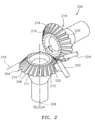
- FIG. 2 is a simplified illustration of a gear assembly 200 (e.g., a spiral beveled gear assembly) that includes an oil scraper 202.
- the assembly comprises a first gear 204 that rotates about a first axis 206 and includes a first gear face (e.g., beveled) 208 with a plurality of first gear teeth, e.g., 210-212 (e.g., spiral).
- a second gear 214 rotates about a second axis 216 and includes a second gear face (e.g., beveled) with a plurality of second gear teeth 218-220 (e.g., spiral), where the first axis 206 is not parallel with the second axis 216.
- the first and second teeth rotatably engage as the first gear 204 rotates about the first axis 206 and the second gear 214 rotates about the second axis 216.
- the scraper 202 includes a distal interference surface 220 that is in face-to-face non-contacting proximity with the plurality of first gear teeth, e.g., 210-212 as the first gear 204 rotates.
- the interference surface 220 may be at an angle with respect to the first axis 206, where the angle is generally consistent with the angle of the first gear face 208, such that the interference surface 220 is positioned in non-contacting face-to-face proximity to a passing first gear tooth.
- the interference surface 220 does not physically contact the rotating teeth 210-212, but instead relies on disruption to the air flow created by the rotating teeth being in close proximity of the interference surface 220.
- the interference surface shall be as close as practically possible to the rotating teeth without touching, including consideration of tolerances, thermal growth and deflections. It is contemplated that the interference surface may include, for example, bumps, protrusions, grooves, etc. to create more of a disruption to the forces that may be entraining the oil. At high RPMs the interference surface 220 interferes with a pressure differential that draws oil into a windage cloud, reducing the amount of entrained oil.
- the shape of the interference surface 220 may be selected to compliment (e.g., match) the shape of the first gear teeth faces.
- the scraper 202 may be a separate component (e.g., metallic) mounted to a rigid nonrotating structure of a gas turbine engine.
- the scraper 202 should be located a sufficient distance from an oil nozzle 224 that delivers oil to the first gear face 208 to lubricate and cool.
- the scraper 202 may be cooperatively located to remove entrained oil of the second gear wheel 214. It is contemplated that the scraper may be on either gear, or both, depending upon the nature of windage and entrainment experienced by any particular gearset.
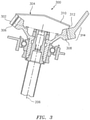
- FIG. 3 is a cross sectional illustration of a shrouded gear assembly 300 with an oil scraper 302 that includes an interference surface 306 integral with a shroud 304.
- the stationary non-contacting interference surface 306 disrupts air pressure adjacent to the rotating teeth of a gear wheel 308 passing in close face-to-face proximity to the interference surface 306. This reduces attractive forces causing oil to be entrained by the rotating gear wheel 308, thus reducing the amount of entrained oil.
- the shroud 304 may be coaxially located over the gear wheel 308, where the shroud includes a base surface 310 and a circumferential sidewall 312 extending from the base surface 310.
- a first cutout 314 is located in the sidewall 310 for the first gear teeth and the second gear teeth to rotatably engage.
- a second cutout may be located in the sidewall with the radially inward extending interference surface 306 operatively positioned in non-contacting face-to-face proximity with teeth of the gear wheel, so the interference surface 306 removes oil entrained adjacent to the plurality of first gear teeth as the first gear rotates.
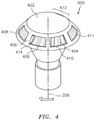
- FIG. 4 is a pictorial illustration of a shrouded gear assembly 400 that includes a shroud 402 and a gear wheel 404.
- the shroud includes a sidewall 406 that comprises a plurality of cutouts 408-412, where at least one of the cutouts such as cutout 409 includes an associated oil scraper 414.
- the oil scraper 414 may be of unitary construction with the sidewall 406, and extends generally radially inward such that the oil scraper disrupts, in a non-contacting manner, forces entraining oil around the rotating gear teeth.
- the cutout 412 provides the cut out for gear mesh with second gear wheel (not shown).
Landscapes
- Engineering & Computer Science (AREA)
- General Engineering & Computer Science (AREA)
- Mechanical Engineering (AREA)
- Chemical & Material Sciences (AREA)
- Combustion & Propulsion (AREA)
- General Details Of Gearings (AREA)
- Gear Transmission (AREA)
Claims (7)
- Zahnradbaugruppe (300; 400), umfassend:ein erstes Zahnrad (308; 404), das sich um eine erste Achse (206) dreht und eine erste Zahnradstirnseite (208) mit einer Vielzahl erster Zahnradzähne (210-212) beinhaltet;ein zweites Zahnrad (214), das sich um eine zweite Achse (216) dreht und eine zweite Zahnradstirnseite mit einer Vielzahl zweiter Zahnradzähne (218-220) beinhaltet, wobei die erste Achse (206) nicht parallel zur zweiten Achse (216) ist und die ersten und die zweiten Zähne (210-212, 218-220) rotierend ineinandergreifen, wenn sich das erste Zahnrad (308; 404) um die erste Achse (206) dreht und sich das zweite Zahnrad (214) um die zweite Achse (216) dreht; undeine Verkleidung (304; 402), die koaxial über der Vielzahl erster Zähne (210-212) angeordnet ist, wobei die Verkleidung (304; 402) eine Grundfläche (310) und eine umlaufende Seitenwand (312; 406), die sich von der Grundfläche (310) aus erstreckt, und eine erste Aussparung (314; 412) in der Seitenwand (312; 406), sodass die ersten Zahnradzähne (210-212) und die zweiten Zahnradzähne (218-220) rotierend ineinandergreifen, und eine zweite Aussparung (409) in der Seitenwand (312; 406) beinhaltet, dadurch gekennzeichnet, dass die zweite Aussparung (409) ferner einen Ölabstreifer (302; 414) umfasst, der eine radial einwärts verlaufende Eingriffsfläche (306) in direkter Nähe zu mindestens einem Teil der Vielzahl erster Zahnradzähne (210-212) beinhaltet,wobei die Eingriffsfläche (306) Öl, das angrenzend an die Vielzahl erster Zahnradzähne (210-212) mitgerissen wurde, entfernt, wenn sich das erste Zahnrad (308; 404) dreht, wobei die Eingriffsfläche (306) eine Störung des Luftdrucks angrenzend an die rotierende erste Vielzahl von Zähnen (210-212), die in enger direkter Nähe zur Eingriffsfläche (306) vorbeilaufen, verursacht, um Kräfte, die Öl mitreißen, in Bezug auf die erste Vielzahl von Zähnen (210-212) zu stören, um die Menge an mitgerissenem Öl zu verringern.
- Zahnradbaugruppe (300; 400) nach Anspruch 1, wobei die Verkleidung (304; 402) und die radial nach innen verlaufende Eingriffsfläche (306) einheitliche Bauteile sind.
- Zahnradbaugruppe (300; 400) nach Anspruch 1 oder 2, wobei die Verkleidung (304; 402) und die radial nach innen verlaufende Eingriffsfläche (306) aus Metallblech gebildet sind.
- The Zahnradbaugruppe (300; 400) nach Anspruch 1 oder 2, wobei die Verkleidung (304; 402) und die radial nach innen verlaufende Eingriffsfläche (306) gegossen sind.
- Zahnradbaugruppe (300; 400) nach einem der Ansprüche 1 bis 4, wobei die Eingriffsfläche (306) in Bezug auf die Vielzahl erster Zahnradzähne (210-212) nicht berührend ist.
- Zahnradbaugruppe (300; 400) nach einem der Ansprüche 1 bis 5, ferner eine dritte Aussparung (408-412) in der Seitenwand (312; 406) mit einer dritten radial einwärts verlaufenden Eingriffsfläche in direkter Nähe zu mindestens einem Teil der ersten Vielzahl von Zähnen (210-212) umfassend, wobei die dritte radial einwärts verlaufende Eingriffsfläche Öl, das angrenzend an die Vielzahl von ersten Zahnradzähnen (210-212) mitgerissen wurde, entfernt, wenn sich das Zahnrad dreht.
- Zahnradbaugruppe (300; 400) nach einem der Ansprüche 1 bis 6, wobei die Form der Eingriffsfläche (306) die Form der Vielzahl erster Zahnradzähne (210-212) komplementiert.
Applications Claiming Priority (1)
| Application Number | Priority Date | Filing Date | Title |
|---|---|---|---|
| US15/609,066 US10648553B2 (en) | 2017-05-31 | 2017-05-31 | Oil scraper |
Publications (3)
| Publication Number | Publication Date |
|---|---|
| EP3409925A2 EP3409925A2 (de) | 2018-12-05 |
| EP3409925A3 EP3409925A3 (de) | 2019-01-02 |
| EP3409925B1 true EP3409925B1 (de) | 2022-03-23 |
Family
ID=62235833
Family Applications (1)
| Application Number | Title | Priority Date | Filing Date |
|---|---|---|---|
| EP18173676.0A Active EP3409925B1 (de) | 2017-05-31 | 2018-05-22 | Ölabstreifer |
Country Status (2)
| Country | Link |
|---|---|
| US (1) | US10648553B2 (de) |
| EP (1) | EP3409925B1 (de) |
Families Citing this family (1)
| Publication number | Priority date | Publication date | Assignee | Title |
|---|---|---|---|---|
| US11306656B2 (en) | 2019-10-24 | 2022-04-19 | Raytheon Technologies Corporation | Oil drainback arrangement for gas turbine engine |
Family Cites Families (14)
| Publication number | Priority date | Publication date | Assignee | Title |
|---|---|---|---|---|
| US5813493A (en) * | 1997-04-15 | 1998-09-29 | Dana Corporation | Lubrication fluid deflector/baffle for a motor vehicle axle assembly |
| US6096198A (en) | 1998-06-11 | 2000-08-01 | Halliburton Energy Services, Inc. | Apparatus for conditioning metal cutting fluids |
| JP4958889B2 (ja) * | 2008-12-05 | 2012-06-20 | 川崎重工業株式会社 | 歯車列の潤滑装置 |
| US8167758B2 (en) | 2008-12-08 | 2012-05-01 | American Axle & Manufacturing, Inc. | Drive axle assembly with gear mesh lubrication systems for lubricating gear mesh and/or differential bearings |
| DE102009014317A1 (de) | 2009-03-25 | 2010-10-07 | Sew-Eurodrive Gmbh & Co. Kg | Getriebe |
| DE102009014316B4 (de) | 2009-03-25 | 2019-03-14 | Sew-Eurodrive Gmbh & Co Kg | Getriebe |
| US8535193B2 (en) | 2011-03-16 | 2013-09-17 | Caterpillar Inc. | Lower powertrain axle shroud |
| DK2762737T3 (en) | 2013-01-31 | 2017-04-10 | Siemens Ag | Directly operated wind turbine with a bearing and method for collecting a lubricant running out of a bearing |
| US9470303B2 (en) | 2013-10-08 | 2016-10-18 | Sikorsky Aircraft Corporation | Self scavenging gear shield |
| US9776508B2 (en) | 2014-04-17 | 2017-10-03 | American Axle & Manufacturing, Inc. | Power take-off unit with hydraulic disconnect |
| US9127760B1 (en) | 2014-04-30 | 2015-09-08 | Fca Us Llc | Differential assembly shroud member for spin loss reduction |
| GB201419812D0 (en) * | 2014-11-07 | 2014-12-24 | Rolls Royce Plc | A shroud assembly |
| US10197150B2 (en) * | 2015-11-23 | 2019-02-05 | United Technologies Corporation | Gear baffle configured with lubricant outlet passage |
| US10221937B2 (en) * | 2016-04-05 | 2019-03-05 | United Technologies Corporation | Slotted oil baffle for gears |
-
2017
- 2017-05-31 US US15/609,066 patent/US10648553B2/en active Active
-
2018
- 2018-05-22 EP EP18173676.0A patent/EP3409925B1/de active Active
Also Published As
| Publication number | Publication date |
|---|---|
| US20180347684A1 (en) | 2018-12-06 |
| EP3409925A2 (de) | 2018-12-05 |
| EP3409925A3 (de) | 2019-01-02 |
| US10648553B2 (en) | 2020-05-12 |
Similar Documents
| Publication | Publication Date | Title |
|---|---|---|
| US11060417B2 (en) | Fluid collection gutter for a geared turbine engine | |
| EP3199837B1 (de) | Getriebeablenkplatte, die mit schmiermitteldurchgangsauslass konfiguriert ist | |
| US11066945B2 (en) | Fluid collection gutter for a geared turbine engine | |
| US10247020B2 (en) | Fluid collection gutter for a geared turbine engine | |
| EP2971553B1 (de) | Rotorschaufel mit einem konischen verzahnungssteg an einem knotenpunkt zwischen einer plattform und einer verengung | |
| EP3415728B1 (de) | Gasturbinenmotor mit rotierendem umkehrverbindungsgetriebe | |
| EP2978938B1 (de) | Turbinenanordnung mit l-förmiger federdichtung | |
| JP2013185584A (ja) | 回転機械で使用するためのシール組立体および回転機械を組み立てる方法 | |
| EP2852741B1 (de) | Gasturbinentriebwerk mit partikelabweiser | |
| JP6431950B2 (ja) | 一体型可撓性熱シールドを有する空気シールを回転させるための方法およびシステム | |
| CN107435592B (zh) | 用于燃气涡轮发动机的轴间密封系统及其组装方法 | |
| EP3388641A1 (de) | Dichtungsanordnung für ein lagergehäuse eines gasturbinentriebwerks und mutter | |
| CN116255448A (zh) | 覆盖将环形齿轮组件联接到输出轴的紧固件的风阻盖 | |
| EP3409925B1 (de) | Ölabstreifer | |
| CA2990788C (en) | Apparatus for a gearbox with multiple scavenge ports | |
| EP2431578B1 (de) | Lageranordnung für Gasturbinenmotor | |
| US12270347B2 (en) | Air turbine starter with damping member |
Legal Events
| Date | Code | Title | Description |
|---|---|---|---|
| PUAI | Public reference made under article 153(3) epc to a published international application that has entered the european phase |
Free format text: ORIGINAL CODE: 0009012 |
|
| STAA | Information on the status of an ep patent application or granted ep patent |
Free format text: STATUS: THE APPLICATION HAS BEEN PUBLISHED |
|
| PUAL | Search report despatched |
Free format text: ORIGINAL CODE: 0009013 |
|
| AK | Designated contracting states |
Kind code of ref document: A2 Designated state(s): AL AT BE BG CH CY CZ DE DK EE ES FI FR GB GR HR HU IE IS IT LI LT LU LV MC MK MT NL NO PL PT RO RS SE SI SK SM TR |
|
| AX | Request for extension of the european patent |
Extension state: BA ME |
|
| AK | Designated contracting states |
Kind code of ref document: A3 Designated state(s): AL AT BE BG CH CY CZ DE DK EE ES FI FR GB GR HR HU IE IS IT LI LT LU LV MC MK MT NL NO PL PT RO RS SE SI SK SM TR |
|
| AX | Request for extension of the european patent |
Extension state: BA ME |
|
| RIC1 | Information provided on ipc code assigned before grant |
Ipc: F16H 57/04 20100101ALI20181127BHEP Ipc: F02C 7/36 20060101AFI20181127BHEP |
|
| STAA | Information on the status of an ep patent application or granted ep patent |
Free format text: STATUS: REQUEST FOR EXAMINATION WAS MADE |
|
| 17P | Request for examination filed |
Effective date: 20190702 |
|
| RBV | Designated contracting states (corrected) |
Designated state(s): AL AT BE BG CH CY CZ DE DK EE ES FI FR GB GR HR HU IE IS IT LI LT LU LV MC MK MT NL NO PL PT RO RS SE SI SK SM TR |
|
| STAA | Information on the status of an ep patent application or granted ep patent |
Free format text: STATUS: EXAMINATION IS IN PROGRESS |
|
| 17Q | First examination report despatched |
Effective date: 20200408 |
|
| RAP1 | Party data changed (applicant data changed or rights of an application transferred) |
Owner name: RAYTHEON TECHNOLOGIES CORPORATION |
|
| GRAP | Despatch of communication of intention to grant a patent |
Free format text: ORIGINAL CODE: EPIDOSNIGR1 |
|
| STAA | Information on the status of an ep patent application or granted ep patent |
Free format text: STATUS: GRANT OF PATENT IS INTENDED |
|
| INTG | Intention to grant announced |
Effective date: 20210929 |
|
| GRAS | Grant fee paid |
Free format text: ORIGINAL CODE: EPIDOSNIGR3 |
|
| GRAA | (expected) grant |
Free format text: ORIGINAL CODE: 0009210 |
|
| STAA | Information on the status of an ep patent application or granted ep patent |
Free format text: STATUS: THE PATENT HAS BEEN GRANTED |
|
| AK | Designated contracting states |
Kind code of ref document: B1 Designated state(s): AL AT BE BG CH CY CZ DE DK EE ES FI FR GB GR HR HU IE IS IT LI LT LU LV MC MK MT NL NO PL PT RO RS SE SI SK SM TR |
|
| REG | Reference to a national code |
Ref country code: GB Ref legal event code: FG4D |
|
| REG | Reference to a national code |
Ref country code: CH Ref legal event code: EP |
|
| REG | Reference to a national code |
Ref country code: IE Ref legal event code: FG4D |
|
| REG | Reference to a national code |
Ref country code: DE Ref legal event code: R096 Ref document number: 602018032529 Country of ref document: DE |
|
| REG | Reference to a national code |
Ref country code: AT Ref legal event code: REF Ref document number: 1477582 Country of ref document: AT Kind code of ref document: T Effective date: 20220415 |
|
| REG | Reference to a national code |
Ref country code: LT Ref legal event code: MG9D |
|
| REG | Reference to a national code |
Ref country code: NL Ref legal event code: MP Effective date: 20220323 |
|
| PG25 | Lapsed in a contracting state [announced via postgrant information from national office to epo] |
Ref country code: SE Free format text: LAPSE BECAUSE OF FAILURE TO SUBMIT A TRANSLATION OF THE DESCRIPTION OR TO PAY THE FEE WITHIN THE PRESCRIBED TIME-LIMIT Effective date: 20220323 Ref country code: RS Free format text: LAPSE BECAUSE OF FAILURE TO SUBMIT A TRANSLATION OF THE DESCRIPTION OR TO PAY THE FEE WITHIN THE PRESCRIBED TIME-LIMIT Effective date: 20220323 Ref country code: NO Free format text: LAPSE BECAUSE OF FAILURE TO SUBMIT A TRANSLATION OF THE DESCRIPTION OR TO PAY THE FEE WITHIN THE PRESCRIBED TIME-LIMIT Effective date: 20220623 Ref country code: LT Free format text: LAPSE BECAUSE OF FAILURE TO SUBMIT A TRANSLATION OF THE DESCRIPTION OR TO PAY THE FEE WITHIN THE PRESCRIBED TIME-LIMIT Effective date: 20220323 Ref country code: HR Free format text: LAPSE BECAUSE OF FAILURE TO SUBMIT A TRANSLATION OF THE DESCRIPTION OR TO PAY THE FEE WITHIN THE PRESCRIBED TIME-LIMIT Effective date: 20220323 Ref country code: BG Free format text: LAPSE BECAUSE OF FAILURE TO SUBMIT A TRANSLATION OF THE DESCRIPTION OR TO PAY THE FEE WITHIN THE PRESCRIBED TIME-LIMIT Effective date: 20220623 |
|
| REG | Reference to a national code |
Ref country code: AT Ref legal event code: MK05 Ref document number: 1477582 Country of ref document: AT Kind code of ref document: T Effective date: 20220323 |
|
| PG25 | Lapsed in a contracting state [announced via postgrant information from national office to epo] |
Ref country code: LV Free format text: LAPSE BECAUSE OF FAILURE TO SUBMIT A TRANSLATION OF THE DESCRIPTION OR TO PAY THE FEE WITHIN THE PRESCRIBED TIME-LIMIT Effective date: 20220323 Ref country code: GR Free format text: LAPSE BECAUSE OF FAILURE TO SUBMIT A TRANSLATION OF THE DESCRIPTION OR TO PAY THE FEE WITHIN THE PRESCRIBED TIME-LIMIT Effective date: 20220624 Ref country code: FI Free format text: LAPSE BECAUSE OF FAILURE TO SUBMIT A TRANSLATION OF THE DESCRIPTION OR TO PAY THE FEE WITHIN THE PRESCRIBED TIME-LIMIT Effective date: 20220323 |
|
| PG25 | Lapsed in a contracting state [announced via postgrant information from national office to epo] |
Ref country code: NL Free format text: LAPSE BECAUSE OF FAILURE TO SUBMIT A TRANSLATION OF THE DESCRIPTION OR TO PAY THE FEE WITHIN THE PRESCRIBED TIME-LIMIT Effective date: 20220323 |
|
| PG25 | Lapsed in a contracting state [announced via postgrant information from national office to epo] |
Ref country code: SM Free format text: LAPSE BECAUSE OF FAILURE TO SUBMIT A TRANSLATION OF THE DESCRIPTION OR TO PAY THE FEE WITHIN THE PRESCRIBED TIME-LIMIT Effective date: 20220323 Ref country code: SK Free format text: LAPSE BECAUSE OF FAILURE TO SUBMIT A TRANSLATION OF THE DESCRIPTION OR TO PAY THE FEE WITHIN THE PRESCRIBED TIME-LIMIT Effective date: 20220323 Ref country code: RO Free format text: LAPSE BECAUSE OF FAILURE TO SUBMIT A TRANSLATION OF THE DESCRIPTION OR TO PAY THE FEE WITHIN THE PRESCRIBED TIME-LIMIT Effective date: 20220323 Ref country code: PT Free format text: LAPSE BECAUSE OF FAILURE TO SUBMIT A TRANSLATION OF THE DESCRIPTION OR TO PAY THE FEE WITHIN THE PRESCRIBED TIME-LIMIT Effective date: 20220725 Ref country code: ES Free format text: LAPSE BECAUSE OF FAILURE TO SUBMIT A TRANSLATION OF THE DESCRIPTION OR TO PAY THE FEE WITHIN THE PRESCRIBED TIME-LIMIT Effective date: 20220323 Ref country code: EE Free format text: LAPSE BECAUSE OF FAILURE TO SUBMIT A TRANSLATION OF THE DESCRIPTION OR TO PAY THE FEE WITHIN THE PRESCRIBED TIME-LIMIT Effective date: 20220323 Ref country code: CZ Free format text: LAPSE BECAUSE OF FAILURE TO SUBMIT A TRANSLATION OF THE DESCRIPTION OR TO PAY THE FEE WITHIN THE PRESCRIBED TIME-LIMIT Effective date: 20220323 Ref country code: AT Free format text: LAPSE BECAUSE OF FAILURE TO SUBMIT A TRANSLATION OF THE DESCRIPTION OR TO PAY THE FEE WITHIN THE PRESCRIBED TIME-LIMIT Effective date: 20220323 |
|
| PG25 | Lapsed in a contracting state [announced via postgrant information from national office to epo] |
Ref country code: PL Free format text: LAPSE BECAUSE OF FAILURE TO SUBMIT A TRANSLATION OF THE DESCRIPTION OR TO PAY THE FEE WITHIN THE PRESCRIBED TIME-LIMIT Effective date: 20220323 Ref country code: IS Free format text: LAPSE BECAUSE OF FAILURE TO SUBMIT A TRANSLATION OF THE DESCRIPTION OR TO PAY THE FEE WITHIN THE PRESCRIBED TIME-LIMIT Effective date: 20220723 Ref country code: AL Free format text: LAPSE BECAUSE OF FAILURE TO SUBMIT A TRANSLATION OF THE DESCRIPTION OR TO PAY THE FEE WITHIN THE PRESCRIBED TIME-LIMIT Effective date: 20220323 |
|
| REG | Reference to a national code |
Ref country code: CH Ref legal event code: PL |
|
| REG | Reference to a national code |
Ref country code: DE Ref legal event code: R097 Ref document number: 602018032529 Country of ref document: DE |
|
| REG | Reference to a national code |
Ref country code: BE Ref legal event code: MM Effective date: 20220531 |
|
| PLBE | No opposition filed within time limit |
Free format text: ORIGINAL CODE: 0009261 |
|
| STAA | Information on the status of an ep patent application or granted ep patent |
Free format text: STATUS: NO OPPOSITION FILED WITHIN TIME LIMIT |
|
| PG25 | Lapsed in a contracting state [announced via postgrant information from national office to epo] |
Ref country code: MC Free format text: LAPSE BECAUSE OF FAILURE TO SUBMIT A TRANSLATION OF THE DESCRIPTION OR TO PAY THE FEE WITHIN THE PRESCRIBED TIME-LIMIT Effective date: 20220323 Ref country code: LU Free format text: LAPSE BECAUSE OF NON-PAYMENT OF DUE FEES Effective date: 20220522 Ref country code: LI Free format text: LAPSE BECAUSE OF NON-PAYMENT OF DUE FEES Effective date: 20220531 Ref country code: DK Free format text: LAPSE BECAUSE OF FAILURE TO SUBMIT A TRANSLATION OF THE DESCRIPTION OR TO PAY THE FEE WITHIN THE PRESCRIBED TIME-LIMIT Effective date: 20220323 Ref country code: CH Free format text: LAPSE BECAUSE OF NON-PAYMENT OF DUE FEES Effective date: 20220531 |
|
| 26N | No opposition filed |
Effective date: 20230102 |
|
| PG25 | Lapsed in a contracting state [announced via postgrant information from national office to epo] |
Ref country code: IE Free format text: LAPSE BECAUSE OF NON-PAYMENT OF DUE FEES Effective date: 20220522 |
|
| PG25 | Lapsed in a contracting state [announced via postgrant information from national office to epo] |
Ref country code: SI Free format text: LAPSE BECAUSE OF FAILURE TO SUBMIT A TRANSLATION OF THE DESCRIPTION OR TO PAY THE FEE WITHIN THE PRESCRIBED TIME-LIMIT Effective date: 20220323 Ref country code: BE Free format text: LAPSE BECAUSE OF NON-PAYMENT OF DUE FEES Effective date: 20220531 |
|
| P01 | Opt-out of the competence of the unified patent court (upc) registered |
Effective date: 20230521 |
|
| PG25 | Lapsed in a contracting state [announced via postgrant information from national office to epo] |
Ref country code: IT Free format text: LAPSE BECAUSE OF FAILURE TO SUBMIT A TRANSLATION OF THE DESCRIPTION OR TO PAY THE FEE WITHIN THE PRESCRIBED TIME-LIMIT Effective date: 20220323 |
|
| PG25 | Lapsed in a contracting state [announced via postgrant information from national office to epo] |
Ref country code: HU Free format text: LAPSE BECAUSE OF FAILURE TO SUBMIT A TRANSLATION OF THE DESCRIPTION OR TO PAY THE FEE WITHIN THE PRESCRIBED TIME-LIMIT; INVALID AB INITIO Effective date: 20180522 |
|
| PG25 | Lapsed in a contracting state [announced via postgrant information from national office to epo] |
Ref country code: MK Free format text: LAPSE BECAUSE OF FAILURE TO SUBMIT A TRANSLATION OF THE DESCRIPTION OR TO PAY THE FEE WITHIN THE PRESCRIBED TIME-LIMIT Effective date: 20220323 Ref country code: CY Free format text: LAPSE BECAUSE OF FAILURE TO SUBMIT A TRANSLATION OF THE DESCRIPTION OR TO PAY THE FEE WITHIN THE PRESCRIBED TIME-LIMIT Effective date: 20220323 |
|
| PG25 | Lapsed in a contracting state [announced via postgrant information from national office to epo] |
Ref country code: TR Free format text: LAPSE BECAUSE OF FAILURE TO SUBMIT A TRANSLATION OF THE DESCRIPTION OR TO PAY THE FEE WITHIN THE PRESCRIBED TIME-LIMIT Effective date: 20220323 |
|
| PG25 | Lapsed in a contracting state [announced via postgrant information from national office to epo] |
Ref country code: MT Free format text: LAPSE BECAUSE OF FAILURE TO SUBMIT A TRANSLATION OF THE DESCRIPTION OR TO PAY THE FEE WITHIN THE PRESCRIBED TIME-LIMIT Effective date: 20220323 |
|
| PGFP | Annual fee paid to national office [announced via postgrant information from national office to epo] |
Ref country code: DE Payment date: 20250423 Year of fee payment: 8 |
|
| PGFP | Annual fee paid to national office [announced via postgrant information from national office to epo] |
Ref country code: GB Payment date: 20250423 Year of fee payment: 8 |
|
| PGFP | Annual fee paid to national office [announced via postgrant information from national office to epo] |
Ref country code: FR Payment date: 20250423 Year of fee payment: 8 |
|
| REG | Reference to a national code |
Ref country code: DE Ref legal event code: R081 Ref document number: 602018032529 Country of ref document: DE Owner name: RTX CORPORATION (N.D.GES.D. STAATES DELAWARE),, US Free format text: FORMER OWNER: RAYTHEON TECHNOLOGIES CORPORATION, FARMINGTON, CT, US |