EP3409896A1 - Pressure equalizing orifice for baffles in vanes - Google Patents
Pressure equalizing orifice for baffles in vanes Download PDFInfo
- Publication number
- EP3409896A1 EP3409896A1 EP18164585.4A EP18164585A EP3409896A1 EP 3409896 A1 EP3409896 A1 EP 3409896A1 EP 18164585 A EP18164585 A EP 18164585A EP 3409896 A1 EP3409896 A1 EP 3409896A1
- Authority
- EP
- European Patent Office
- Prior art keywords
- baffle
- vane
- cavity
- module
- upstream
- Prior art date
- Legal status (The legal status is an assumption and is not a legal conclusion. Google has not performed a legal analysis and makes no representation as to the accuracy of the status listed.)
- Granted
Links
Images


Classifications
-
- F—MECHANICAL ENGINEERING; LIGHTING; HEATING; WEAPONS; BLASTING
- F01—MACHINES OR ENGINES IN GENERAL; ENGINE PLANTS IN GENERAL; STEAM ENGINES
- F01D—NON-POSITIVE DISPLACEMENT MACHINES OR ENGINES, e.g. STEAM TURBINES
- F01D9/00—Stators
- F01D9/06—Fluid supply conduits to nozzles or the like
- F01D9/065—Fluid supply or removal conduits traversing the working fluid flow, e.g. for lubrication-, cooling-, or sealing fluids
-
- F—MECHANICAL ENGINEERING; LIGHTING; HEATING; WEAPONS; BLASTING
- F28—HEAT EXCHANGE IN GENERAL
- F28F—DETAILS OF HEAT-EXCHANGE AND HEAT-TRANSFER APPARATUS, OF GENERAL APPLICATION
- F28F13/00—Arrangements for modifying heat-transfer, e.g. increasing, decreasing
- F28F13/02—Arrangements for modifying heat-transfer, e.g. increasing, decreasing by influencing fluid boundary
-
- F—MECHANICAL ENGINEERING; LIGHTING; HEATING; WEAPONS; BLASTING
- F01—MACHINES OR ENGINES IN GENERAL; ENGINE PLANTS IN GENERAL; STEAM ENGINES
- F01D—NON-POSITIVE DISPLACEMENT MACHINES OR ENGINES, e.g. STEAM TURBINES
- F01D25/00—Component parts, details, or accessories, not provided for in, or of interest apart from, other groups
- F01D25/08—Cooling; Heating; Heat-insulation
- F01D25/12—Cooling
-
- F—MECHANICAL ENGINEERING; LIGHTING; HEATING; WEAPONS; BLASTING
- F01—MACHINES OR ENGINES IN GENERAL; ENGINE PLANTS IN GENERAL; STEAM ENGINES
- F01D—NON-POSITIVE DISPLACEMENT MACHINES OR ENGINES, e.g. STEAM TURBINES
- F01D5/00—Blades; Blade-carrying members; Heating, heat-insulating, cooling or antivibration means on the blades or the members
- F01D5/12—Blades
- F01D5/14—Form or construction
- F01D5/18—Hollow blades, i.e. blades with cooling or heating channels or cavities; Heating, heat-insulating or cooling means on blades
- F01D5/187—Convection cooling
- F01D5/188—Convection cooling with an insert in the blade cavity to guide the cooling fluid, e.g. forming a separation wall
- F01D5/189—Convection cooling with an insert in the blade cavity to guide the cooling fluid, e.g. forming a separation wall the insert having a tubular cross-section, e.g. airfoil shape
-
- F—MECHANICAL ENGINEERING; LIGHTING; HEATING; WEAPONS; BLASTING
- F01—MACHINES OR ENGINES IN GENERAL; ENGINE PLANTS IN GENERAL; STEAM ENGINES
- F01D—NON-POSITIVE DISPLACEMENT MACHINES OR ENGINES, e.g. STEAM TURBINES
- F01D9/00—Stators
- F01D9/02—Nozzles; Nozzle boxes; Stator blades; Guide conduits, e.g. individual nozzles
- F01D9/04—Nozzles; Nozzle boxes; Stator blades; Guide conduits, e.g. individual nozzles forming ring or sector
- F01D9/045—Nozzles; Nozzle boxes; Stator blades; Guide conduits, e.g. individual nozzles forming ring or sector for radial flow machines or engines
-
- F—MECHANICAL ENGINEERING; LIGHTING; HEATING; WEAPONS; BLASTING
- F01—MACHINES OR ENGINES IN GENERAL; ENGINE PLANTS IN GENERAL; STEAM ENGINES
- F01D—NON-POSITIVE DISPLACEMENT MACHINES OR ENGINES, e.g. STEAM TURBINES
- F01D9/00—Stators
- F01D9/02—Nozzles; Nozzle boxes; Stator blades; Guide conduits, e.g. individual nozzles
- F01D9/04—Nozzles; Nozzle boxes; Stator blades; Guide conduits, e.g. individual nozzles forming ring or sector
- F01D9/048—Nozzles; Nozzle boxes; Stator blades; Guide conduits, e.g. individual nozzles forming ring or sector for radial admission
-
- F—MECHANICAL ENGINEERING; LIGHTING; HEATING; WEAPONS; BLASTING
- F05—INDEXING SCHEMES RELATING TO ENGINES OR PUMPS IN VARIOUS SUBCLASSES OF CLASSES F01-F04
- F05D—INDEXING SCHEME FOR ASPECTS RELATING TO NON-POSITIVE-DISPLACEMENT MACHINES OR ENGINES, GAS-TURBINES OR JET-PROPULSION PLANTS
- F05D2240/00—Components
- F05D2240/10—Stators
- F05D2240/12—Fluid guiding means, e.g. vanes
- F05D2240/126—Baffles or ribs
-
- F—MECHANICAL ENGINEERING; LIGHTING; HEATING; WEAPONS; BLASTING
- F05—INDEXING SCHEMES RELATING TO ENGINES OR PUMPS IN VARIOUS SUBCLASSES OF CLASSES F01-F04
- F05D—INDEXING SCHEME FOR ASPECTS RELATING TO NON-POSITIVE-DISPLACEMENT MACHINES OR ENGINES, GAS-TURBINES OR JET-PROPULSION PLANTS
- F05D2260/00—Function
- F05D2260/20—Heat transfer, e.g. cooling
- F05D2260/201—Heat transfer, e.g. cooling by impingement of a fluid
-
- F—MECHANICAL ENGINEERING; LIGHTING; HEATING; WEAPONS; BLASTING
- F05—INDEXING SCHEMES RELATING TO ENGINES OR PUMPS IN VARIOUS SUBCLASSES OF CLASSES F01-F04
- F05D—INDEXING SCHEME FOR ASPECTS RELATING TO NON-POSITIVE-DISPLACEMENT MACHINES OR ENGINES, GAS-TURBINES OR JET-PROPULSION PLANTS
- F05D2260/00—Function
- F05D2260/20—Heat transfer, e.g. cooling
- F05D2260/221—Improvement of heat transfer
- F05D2260/2214—Improvement of heat transfer by increasing the heat transfer surface
-
- Y—GENERAL TAGGING OF NEW TECHNOLOGICAL DEVELOPMENTS; GENERAL TAGGING OF CROSS-SECTIONAL TECHNOLOGIES SPANNING OVER SEVERAL SECTIONS OF THE IPC; TECHNICAL SUBJECTS COVERED BY FORMER USPC CROSS-REFERENCE ART COLLECTIONS [XRACs] AND DIGESTS
- Y02—TECHNOLOGIES OR APPLICATIONS FOR MITIGATION OR ADAPTATION AGAINST CLIMATE CHANGE
- Y02T—CLIMATE CHANGE MITIGATION TECHNOLOGIES RELATED TO TRANSPORTATION
- Y02T50/00—Aeronautics or air transport
- Y02T50/60—Efficient propulsion technologies, e.g. for aircraft
Definitions
- Exemplary embodiments pertain to the art of baffle design and more specifically to baffles disposed in a vane cavity subject to a flow of cooling air.
- baffles With completely sealed baffles disposed in vane cavities in gas turbine engines under operating conditions, air inside the baffle may remain at atmospheric pressure while pressure in airflow outside of the baffle may be greater. Thick baffle walls or numerous ribs inside the baffle may be required to prevent the baffle from collapsing. The thick walls or extra ribs may result in extra weight and design complexity. Accordingly there is a need for a baffle design providing a lower pressure difference between the inside and outside of the baffle during operating conditions.
- a module for a gas turbine engine comprising a disk rotatable about an engine central axis and a vane fixedly disposed upstream of the disk, the vane being hollow and including a vane cavity, the vane cavity having a vane longitudinal span between a vane upstream opening and vane downstream opening, the vane including: a baffle fixedly supported within the vane cavity, the baffle having a hollow interior and having a baffle longitudinal span between a baffle upstream surface and a baffle downstream surface, the baffle longitudinal span being less than the vane longitudinal span to define a partial space eater baffle; and wherein a baffle opening area fluidly connects the vane cavity to the baffle interior, and the baffle opening area is between 5.0 x 10 ⁇ -5 square inches to 1.5 x 10 ⁇ -3 square inches.
- further embodiments may include a ratio of a baffle volume to a baffle opening area is between 10 inches and 500 inches.
- a baffle volume is between 1.6 x 10 ⁇ -2 cubic inches and 0.4 cubic inches.
- a baffle longitudinal span is between 0.3 inches and 2.0 inches.
- further embodiments may include that the baffle upstream surface and baffle downstream surface each forms a wedge, and the baffle opening area is on a baffle upstream wedge vertex or a baffle downstream wedge vertex.
- further embodiments may include that a baffle first side wall and a baffle second side wall, each baffle side wall extending between the baffle upstream surface and the baffle downstream surface, and the baffle opening area is on one or more of the baffle first side wall, the baffle second side wall, the baffle upstream surface and the baffle downstream surface.
- further embodiments may include that the baffle opening area is distributed on each baffle side wall at a same longitudinal position.
- further embodiments may include that the baffle downstream surface forms a wedge, and the baffle opening area is on a baffle side surface and on the baffle downstream vertex.
- baffle openings area is shaped as a circle, oval, racetrack or round-edge slot.
- a gas turbine engine comprising a module having one or more of the above features. Also disclosed is a method of equalizing pressure between a cavity of a vane and an interior of a baffle disposed within the vane, wherein the vane is in a module within a gas turbine engine, the module includes a rotating disk and the vane is upstream of the rotating disk, the vane cavity having a vane longitudinal span between a vane upstream opening and vane downstream opening, the baffle having a baffle longitudinal span between a baffle upstream surface and a baffle downstream surface, the baffle longitudinal span being less than the vane longitudinal span to define a partial space eater baffle; the method comprising: transferring a flow of cooling air through the vane cavity, from a radial outer end of the vane cavity to a radial inner end of the vane cavity; and diverting a portion of flow of cooling air into one or more baffle openings fluidly connecting the baffle cavity to the vane cavity; wherein a baffle opening area fluidly connect
- FIG. 1 schematically illustrates a gas turbine engine 20.
- the gas turbine engine 20 is disclosed herein as a two-spool turbofan that generally incorporates a fan section 22, a compressor section 24, a combustor section 26 and a turbine section 28.
- Alternative engines might include an augmentor section (not shown) among other systems or features.
- the fan section 22 drives air along a bypass flow path B in a bypass duct, while the compressor section 24 drives air along a core flow path C for compression and communication into the combustor section 26 then expansion through the turbine section 28.
- the exemplary engine 20 generally includes a low speed spool 30 and a high speed spool 32 mounted for rotation about an engine central longitudinal axis A relative to an engine static structure 36 via several bearing systems 38. It should be understood that various bearing systems 38 at various locations may alternatively or additionally be provided, and the location of bearing systems 38 may be varied as appropriate to the application.
- the low speed spool 30 generally includes an inner shaft 40 that interconnects a fan 42, a low pressure compressor 44 and a low pressure turbine 46.
- the inner shaft 40 is connected to the fan 42 through a speed change mechanism, which in exemplary gas turbine engine 20 is illustrated as a geared architecture 48 to drive the fan 42 at a lower speed than the low speed spool 30.
- the high speed spool 32 includes an outer shaft 50 that interconnects a high pressure compressor 52 and high pressure turbine 54.
- a combustor 56 is arranged in exemplary gas turbine 20 between the high pressure compressor 52 and the high pressure turbine 54.
- An engine static structure 36 is arranged generally between the high pressure turbine 54 and the low pressure turbine 46.
- the engine static structure 36 further supports bearing systems 38 in the turbine section 28.
- the inner shaft 40 and the outer shaft 50 are concentric and rotate via bearing systems 38 about the engine central longitudinal axis A which is collinear with their longitudinal axes.
- each of the positions of the fan section 22, compressor section 24, combustor section 26, turbine section 28, and fan drive gear system 48 may be varied.
- gear system 48 may be located aft of combustor section 26 or even aft of turbine section 28, and fan section 22 may be positioned forward or aft of the location of gear system 48.
- the engine 20 in one example is a high-bypass geared aircraft engine.
- the engine 20 bypass ratio is greater than about six (6), with an example embodiment being greater than about ten (10)
- the geared architecture 48 is an epicyclic gear train, such as a planetary gear system or other gear system, with a gear reduction ratio of greater than about 2.3
- the low pressure turbine 46 has a pressure ratio that is greater than about five.
- the engine 20 bypass ratio is greater than about ten (10:1)
- the fan diameter is significantly larger than that of the low pressure compressor 44
- the low pressure turbine 46 has a pressure ratio that is greater than about five 5:1.
- Low pressure turbine 46 pressure ratio is pressure measured prior to inlet of low pressure turbine 46 as related to the pressure at the outlet of the low pressure turbine 46 prior to an exhaust nozzle.
- the geared architecture 48 may be an epicycle gear train, such as a planetary gear system or other gear system, with a gear reduction ratio of greater than about 2.3:1. It should be understood, however, that the above parameters are only exemplary of one embodiment of a geared architecture engine and that the present disclosure is applicable to other gas turbine engines including direct drive turbofans.
- the fan section 22 of the engine 20 is designed for a particular flight condition--typically cruise at about 0.8Mach and about 35,000 feet (10,688 meters).
- 'TSFC' Thrust Specific Fuel Consumption
- Low fan pressure ratio is the pressure ratio across the fan blade alone, without a Fan Exit Guide Vane (“FEGV”) system.
- the low fan pressure ratio as disclosed herein according to one non-limiting embodiment is less than about 1.45.
- Low corrected fan tip speed is the actual fan tip speed in ft/sec divided by an industry standard temperature correction of [(Tram °R)/(518.7 °R)] 0.5 .
- the "Low corrected fan tip speed” as disclosed herein according to one non-limiting embodiment is less than about 1150 ft/second (350.5 m/sec).
- the engine axis A illustrated in FIG. 1 is disposed along a longitudinal axis of the coordinate system and at a radial center or inner most portion of the coordinate system.
- the engine turbine section 28 is disposed downstream or aft of the compressor section 24.
- cooling designs in a turbine section 28 for a gas turbine engine 20 may utilize a vane 106 disposed between axially adjacent bladed full hoop disks 108, 108a having respective blades 109, 109a.
- Vane 106 may be disposed radially between an inner air seal 112 and a full hoop case 114 on an outer side.
- Inner air seal 112 may be a full hoop structure supported by opposing vanes, including vane 106, separated at one hundred and eighty (180) degrees in circumference.
- Vane 106 may be in turn supported by a full hoop case 114 through segmented vane hooks 117, 117a.
- Full hoop cover plates 115, 115a may minimize leakage between vane 106 and blades 109, 109a.
- Vane 106 may be radially supported by full hoop case 114 with segmented case hooks 116, 116a in mechanical connection with segmented vane hooks 117, 117a.
- Vane 106 may be circumferentially supported between circumferentially adjacent vanes by feather seals 119, 119a that may minimize leakage between the adjacent vanes into the gas path.
- a turbine cooling air (TCA) conduit 126 may provide cooling air into an outer diameter vane cavity 124.
- Vane 106 may be hollow so that air may travel radially into and longitudinally downstream through vane 106 via a central vane cavity 122, and thereafter into a vane inner diameter cavity 123. Thereafter air may travel through an orifice 120 in inner air seal 112 and into a rotor cavity 121.
- vane 106 is illustrated in a radial direction, but other orientations for vane 106 are within the scope of the disclosure.
- fluid such as cooling air flows into vane cavity 122 through an upstream opening illustrated herein as outer diameter cavity 124 and out through a downstream opening in vane cavity 122 illustrated herein as inner diameter cavity 123.
- a longitudinal span of vane cavity 122 being between such openings.
- central vane cavity 122 may include longitudinally extending vane walls including suction-side vane wall 135 and pressure-side vane wall 135a spaced therefrom. As illustrated in FIG. 4a , vane walls 135, 135a guide a flow 138 of turbine cooling air through vane 106.
- baffles 130, 130a, 130b which may be partial space eater baffles which in the non-limiting illustration are axially adjacent and radially aligned with each other.
- the illustrated configuration is not intended to limit the number, shape or location of baffles within the guide vane 106.
- partial space eater baffle 130 may have a smaller longitudinal span than the vane 106.
- Baffle 130 is illustrated as being centered within vane 106, but such position is not limiting.
- Baffle 130 may be hollow and have an interior defining an internal baffle cavity 129.
- Baffle cavity 129 may have a plurality of baffle cavity walls, including longitudinal upstream walls 125, 125a, longitudinal downstream walls 127, 127a, a longitudinally extending suction-side wall 134 and a longitudinally extending pressure-side wall 134a. Though longitudinally extending side walls 134, 134a are illustrated herein as radially extending, it will be appreciated that the longitudinal orientation of the baffle 130 may be aligned with the longitudinal orientation of the vane 106.
- Opposing end walls 125, 125a, 127, 127a meet at respective upstream apex 125b and downstream apex 127b to define respective profile shapes of an upstream and a downstream wedge.
- other shapes are known for the longitudinally outer walls of the partial space eater baffle 130, such as flat 125c in baffle 130 FIG. 3c and semi-circular 125d in baffle 130 in FIG. 3d .
- Baffle 130 may be positioned in vane 106 by baffle standoffs 132, 132a, 132b, 132c.
- baffle cavity 129 may be atmospheric and substantially lower than pressure within vane cavity 122. This differential pressure may subject baffle 130 to a collapse.
- baffle 130 may include an opening area defined by an opening 140 in upstream wall 125a of baffle 130, facing pressure-side wall 135a of vane 106.
- the opening 140 may pressurize the baffle cavity 129 at engine operating conditions.
- opening 140 may be disposed on upstream wall 125 of baffle 130, facing suction-side wall 135 of vane 106.
- opening 140 may be at upstream apex 125b of baffle 130.
- opening 140 may be on side wall 134 of baffle 130, facing suction-side wall 135 of vane 106.
- opening 140 may be on downstream wall 127 of baffle 130, facing suction-side wall 135 of vane 106.
- opening 140 in baffle 130 may be circular. In FIG. 6b , opening 140 may be oval. In FIG. 6c , opening 140 in baffle 130 may be in the shape of a racetrack or round-edged slot. In FIG. 6d , opening 140 in baffle 130 may be rectangular or in the shape of a square-edge slot.
- opening 140 in baffle 130 may be circular.
- opening 140 in baffle 130 may be oval.
- opening 140 in baffle 130 may be in the shape of a racetrack or round-edged slot.
- opening 140 in baffle 130 may be rectangular or in the shape of a square-edge slot.
- FIGS. 7a and 7b illustrate a plurality of openings in baffle 130.
- a plurality of openings 140, 140a, 140b may be distributed on both side walls 134, 134a of the baffle 130.
- the plurality of openings may be used to ensure that pressures in and around the baffles 130 is equalized.
- openings 140, 140a are illustrated, one on side wall 134 of baffle 130 and one on downstream apex 127b of baffle 130.
- the combination of the two openings 140, 140a may allow some flow to travel through side wall 134a and exit apex 127b of baffle 130, filling in part of a wake generated by baffle 130, and merging in the same direction with cooling flow 138 outside baffle 130, which may minimizing pressure loss.
- Openings 140, 140a may be sized to tailor the flow in and around baffle 130.
- openings 140, 140a may be sized to keep a majority of the flow outside baffle 130.
- the baffle opening area may be between 5.0 x 10 ⁇ -5 square inches to 1.5 x 10 ⁇ -3 square inches.
- a ratio of a baffle volume to a baffle opening area may be between 10 inches and 500 inches
- the baffle volume may be between 1.6 x 10 ⁇ -2 cubic inches and 0.4 cubic inches
- baffle longitudinal span may be between 0.3 inches and 2.0 inches.
Landscapes
- Engineering & Computer Science (AREA)
- Mechanical Engineering (AREA)
- General Engineering & Computer Science (AREA)
- Physics & Mathematics (AREA)
- Fluid Mechanics (AREA)
- Thermal Sciences (AREA)
- Turbine Rotor Nozzle Sealing (AREA)
Abstract
Description
- This invention was made with Government support under Contract Number FA8650-09-D-2923-0021 awarded by the United States Airforce. The Government has certain rights in the invention.
- Exemplary embodiments pertain to the art of baffle design and more specifically to baffles disposed in a vane cavity subject to a flow of cooling air.
- With completely sealed baffles disposed in vane cavities in gas turbine engines under operating conditions, air inside the baffle may remain at atmospheric pressure while pressure in airflow outside of the baffle may be greater. Thick baffle walls or numerous ribs inside the baffle may be required to prevent the baffle from collapsing. The thick walls or extra ribs may result in extra weight and design complexity. Accordingly there is a need for a baffle design providing a lower pressure difference between the inside and outside of the baffle during operating conditions.
- Disclosed is a module for a gas turbine engine, the module comprising a disk rotatable about an engine central axis and a vane fixedly disposed upstream of the disk, the vane being hollow and including a vane cavity, the vane cavity having a vane longitudinal span between a vane upstream opening and vane downstream opening, the vane including: a baffle fixedly supported within the vane cavity, the baffle having a hollow interior and having a baffle longitudinal span between a baffle upstream surface and a baffle downstream surface, the baffle longitudinal span being less than the vane longitudinal span to define a partial space eater baffle; and wherein a baffle opening area fluidly connects the vane cavity to the baffle interior, and the baffle opening area is between 5.0 x 10^-5 square inches to 1.5 x 10^-3 square inches..
- In addition to one or more of the features described above, or as an alternative, further embodiments may include a ratio of a baffle volume to a baffle opening area is between 10 inches and 500 inches.
- In addition to one or more of the features described above, or as an alternative, further embodiments may include that a baffle volume is between 1.6 x 10^-2 cubic inches and 0.4 cubic inches.
- In addition to one or more of the features described above, or as an alternative, further embodiments may include that a baffle longitudinal span is between 0.3 inches and 2.0 inches.
- In addition to one or more of the features described above, or as an alternative, further embodiments may include that the baffle upstream surface and baffle downstream surface each forms a wedge, and the baffle opening area is on a baffle upstream wedge vertex or a baffle downstream wedge vertex.
- In addition to one or more of the features described above, or as an alternative, further embodiments may include that a baffle first side wall and a baffle second side wall, each baffle side wall extending between the baffle upstream surface and the baffle downstream surface, and the baffle opening area is on one or more of the baffle first side wall, the baffle second side wall, the baffle upstream surface and the baffle downstream surface.
- In addition to one or more of the features described above, or as an alternative, further embodiments may include that the baffle opening area is distributed on each baffle side wall at a same longitudinal position.
- In addition to one or more of the features described above, or as an alternative, further embodiments may include that the baffle downstream surface forms a wedge, and the baffle opening area is on a baffle side surface and on the baffle downstream vertex.
- In addition to one or more of the features described above, or as an alternative, further embodiments may include that the baffle openings area is shaped as a circle, oval, racetrack or round-edge slot.
- Further disclosed is a gas turbine engine comprising a module having one or more of the above features. Also disclosed is a method of equalizing pressure between a cavity of a vane and an interior of a baffle disposed within the vane, wherein the vane is in a module within a gas turbine engine, the module includes a rotating disk and the vane is upstream of the rotating disk, the vane cavity having a vane longitudinal span between a vane upstream opening and vane downstream opening, the baffle having a baffle longitudinal span between a baffle upstream surface and a baffle downstream surface, the baffle longitudinal span being less than the vane longitudinal span to define a partial space eater baffle; the method comprising: transferring a flow of cooling air through the vane cavity, from a radial outer end of the vane cavity to a radial inner end of the vane cavity; and diverting a portion of flow of cooling air into one or more baffle openings fluidly connecting the baffle cavity to the vane cavity; wherein a baffle opening area fluidly connects the vane cavity to the baffle interior, and the baffle opening area is between 5.0 x 10^-5 square inches to 1.5 x 10^-3 square inches. Moreover, the method may comprise one or more of the above disclosed features.
- The following descriptions should not be considered limiting in any way. With reference to the accompanying drawings, like elements are numbered alike:
-
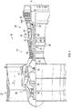
FIG. 1 is a partial cross section of a portion of a gas turbine engine according to an embodiment; -
FIG. 2 illustrates baffles in a vane according to a disclosed embodiment; -
FIGS. 3A-3D illustrate further details of baffles according to disclosed embodiments, whereFIG. 3B illustrates the baffle ofFIG. 3A cut along line B-B; -
FIGS. 4A- 4B illustrate further details of baffles according to disclosed embodiments; -
FIGS. 5A-5D illustrate baffles according to disclosed embodiments; -
FIGS. 6A-6D illustrate baffles according to disclosed embodiments; and -
FIGS. 7A- 7B illustrate baffles according to disclosed embodiments. - A detailed description of one or more embodiments of the disclosed apparatus and method are presented herein by way of exemplification and not limitation with reference to the Figures.
-
FIG. 1 schematically illustrates agas turbine engine 20. Thegas turbine engine 20 is disclosed herein as a two-spool turbofan that generally incorporates afan section 22, acompressor section 24, acombustor section 26 and aturbine section 28. Alternative engines might include an augmentor section (not shown) among other systems or features. Thefan section 22 drives air along a bypass flow path B in a bypass duct, while thecompressor section 24 drives air along a core flow path C for compression and communication into thecombustor section 26 then expansion through theturbine section 28. Although depicted as a two-spool turbofan gas turbine engine in the disclosed non-limiting embodiment, it should be understood that the concepts described herein are not limited to use with two-spool turbofans as the teachings may be applied to other types of turbine engines including three-spool architectures. - The
exemplary engine 20 generally includes alow speed spool 30 and a high speed spool 32 mounted for rotation about an engine central longitudinal axis A relative to an enginestatic structure 36 viaseveral bearing systems 38. It should be understood thatvarious bearing systems 38 at various locations may alternatively or additionally be provided, and the location ofbearing systems 38 may be varied as appropriate to the application. - The
low speed spool 30 generally includes aninner shaft 40 that interconnects afan 42, alow pressure compressor 44 and alow pressure turbine 46. Theinner shaft 40 is connected to thefan 42 through a speed change mechanism, which in exemplarygas turbine engine 20 is illustrated as a gearedarchitecture 48 to drive thefan 42 at a lower speed than thelow speed spool 30. The high speed spool 32 includes anouter shaft 50 that interconnects ahigh pressure compressor 52 andhigh pressure turbine 54. Acombustor 56 is arranged inexemplary gas turbine 20 between thehigh pressure compressor 52 and thehigh pressure turbine 54. An enginestatic structure 36 is arranged generally between thehigh pressure turbine 54 and thelow pressure turbine 46. The enginestatic structure 36 further supports bearingsystems 38 in theturbine section 28. Theinner shaft 40 and theouter shaft 50 are concentric and rotate viabearing systems 38 about the engine central longitudinal axis A which is collinear with their longitudinal axes. - The core airflow is compressed by the
low pressure compressor 44 then thehigh pressure compressor 52, mixed and burned with fuel in thecombustor 56, then expanded over thehigh pressure turbine 54 andlow pressure turbine 46. Theturbines low speed spool 30 and high speed spool 32 in response to the expansion. It will be appreciated that each of the positions of thefan section 22,compressor section 24,combustor section 26,turbine section 28, and fandrive gear system 48 may be varied. For example,gear system 48 may be located aft ofcombustor section 26 or even aft ofturbine section 28, andfan section 22 may be positioned forward or aft of the location ofgear system 48. - The
engine 20 in one example is a high-bypass geared aircraft engine. In a further example, theengine 20 bypass ratio is greater than about six (6), with an example embodiment being greater than about ten (10), the gearedarchitecture 48 is an epicyclic gear train, such as a planetary gear system or other gear system, with a gear reduction ratio of greater than about 2.3 and thelow pressure turbine 46 has a pressure ratio that is greater than about five. In one disclosed embodiment, theengine 20 bypass ratio is greater than about ten (10:1), the fan diameter is significantly larger than that of thelow pressure compressor 44, and thelow pressure turbine 46 has a pressure ratio that is greater than about five 5:1.Low pressure turbine 46 pressure ratio is pressure measured prior to inlet oflow pressure turbine 46 as related to the pressure at the outlet of thelow pressure turbine 46 prior to an exhaust nozzle. The gearedarchitecture 48 may be an epicycle gear train, such as a planetary gear system or other gear system, with a gear reduction ratio of greater than about 2.3:1. It should be understood, however, that the above parameters are only exemplary of one embodiment of a geared architecture engine and that the present disclosure is applicable to other gas turbine engines including direct drive turbofans. - A significant amount of thrust is provided by the bypass flow B due to the high bypass ratio. The
fan section 22 of theengine 20 is designed for a particular flight condition--typically cruise at about 0.8Mach and about 35,000 feet (10,688 meters). The flight condition of 0.8 Mach and 35,000 ft (10,688 meters), with the engine at its best fuel consumption--also known as "bucket cruise Thrust Specific Fuel Consumption ('TSFC')"--is the industry standard parameter of lbm of fuel being burned divided by lbf of thrust the engine produces at that minimum point. "Low fan pressure ratio" is the pressure ratio across the fan blade alone, without a Fan Exit Guide Vane ("FEGV") system. The low fan pressure ratio as disclosed herein according to one non-limiting embodiment is less than about 1.45. "Low corrected fan tip speed" is the actual fan tip speed in ft/sec divided by an industry standard temperature correction of [(Tram °R)/(518.7 °R)]0.5. The "Low corrected fan tip speed" as disclosed herein according to one non-limiting embodiment is less than about 1150 ft/second (350.5 m/sec). - Further reference to features of the disclosed embodiments is made relative to a typical cylindrical coordinate system. The engine axis A illustrated in
FIG. 1 is disposed along a longitudinal axis of the coordinate system and at a radial center or inner most portion of the coordinate system. Theengine turbine section 28 is disposed downstream or aft of thecompressor section 24. - As illustrated in
FIGS. 1 and2 , cooling designs in aturbine section 28 for agas turbine engine 20 may utilize avane 106 disposed between axially adjacent bladedfull hoop disks respective blades Vane 106 may be disposed radially between aninner air seal 112 and afull hoop case 114 on an outer side.Inner air seal 112 may be a full hoop structure supported by opposing vanes, includingvane 106, separated at one hundred and eighty (180) degrees in circumference.Vane 106 may be in turn supported by afull hoop case 114 through segmented vane hooks 117, 117a. Fullhoop cover plates vane 106 andblades Vane 106 may be radially supported byfull hoop case 114 with segmented case hooks 116, 116a in mechanical connection with segmented vane hooks 117, 117a.Vane 106 may be circumferentially supported between circumferentially adjacent vanes byfeather seals - A turbine cooling air (TCA)
conduit 126 may provide cooling air into an outerdiameter vane cavity 124.Vane 106 may be hollow so that air may travel radially into and longitudinally downstream throughvane 106 via acentral vane cavity 122, and thereafter into a vaneinner diameter cavity 123. Thereafter air may travel through anorifice 120 ininner air seal 112 and into arotor cavity 121. - It is to be appreciated that the longitudinal orientation of
vane 106 is illustrated in a radial direction, but other orientations forvane 106 are within the scope of the disclosure. In such alternate vane orientations, fluid such as cooling air flows intovane cavity 122 through an upstream opening illustrated herein asouter diameter cavity 124 and out through a downstream opening invane cavity 122 illustrated herein asinner diameter cavity 123. A longitudinal span ofvane cavity 122 being between such openings. - As illustrated in
FIG. 3b ,central vane cavity 122 may include longitudinally extending vane walls including suction-side vane wall 135 and pressure-side vane wall 135a spaced therefrom. As illustrated inFIG. 4a ,vane walls flow 138 of turbine cooling air throughvane 106. - As illustrated in
FIG. 3a , withinvane cavity 122 there may be one ormore baffles guide vane 106. As illustrated inFIGS. 3a and 3b , partialspace eater baffle 130 may have a smaller longitudinal span than thevane 106.Baffle 130 is illustrated as being centered withinvane 106, but such position is not limiting. -
Baffle 130 may be hollow and have an interior defining aninternal baffle cavity 129.Baffle cavity 129 may have a plurality of baffle cavity walls, including longitudinalupstream walls downstream walls 127, 127a, a longitudinally extending suction-side wall 134 and a longitudinally extending pressure-side wall 134a. Though longitudinally extendingside walls baffle 130 may be aligned with the longitudinal orientation of thevane 106. - Opposing
end walls upstream apex 125b and downstream apex 127b to define respective profile shapes of an upstream and a downstream wedge. However, other shapes are known for the longitudinally outer walls of the partialspace eater baffle 130, such as flat 125c inbaffle 130FIG. 3c and semi-circular 125d inbaffle 130 inFIG. 3d .Baffle 130 may be positioned invane 106 bybaffle standoffs - During engine operating conditions, with cooling air flowing upstream to downstream within the
vane 106 pressure insidebaffle cavity 129 may be atmospheric and substantially lower than pressure withinvane cavity 122. This differential pressure may subject baffle 130 to a collapse. - In
FIG. 4b , baffle 130 may include an opening area defined by anopening 140 inupstream wall 125a ofbaffle 130, facing pressure-side wall 135a ofvane 106. Theopening 140 may pressurize thebaffle cavity 129 at engine operating conditions. InFIG. 5a , opening 140 may be disposed onupstream wall 125 ofbaffle 130, facing suction-side wall 135 ofvane 106. InFIG. 5b , opening 140 may be at upstream apex 125b ofbaffle 130. InFIG. 5c opening 140 may be onside wall 134 ofbaffle 130, facing suction-side wall 135 ofvane 106. InFIG. 5d , opening 140 may be ondownstream wall 127 ofbaffle 130, facing suction-side wall 135 ofvane 106. - Turning to
FIG. 6a , opening 140 inbaffle 130 may be circular. InFIG. 6b , opening 140 may be oval. InFIG. 6c , opening 140 inbaffle 130 may be in the shape of a racetrack or round-edged slot. InFIG. 6d , opening 140 inbaffle 130 may be rectangular or in the shape of a square-edge slot. One of ordinary skill would recognize that the shapes illustrated herein are not limiting. -
FIGS. 7a and 7b illustrate a plurality of openings inbaffle 130. For example, inFIG. 7a , a plurality ofopenings side walls baffle 130. In the illustration, there may be two openings, e.g., 140, 140b on each of theside walls baffles 130 is equalized. - In
FIG. 7b ,plural openings side wall 134 ofbaffle 130 and one ondownstream apex 127b ofbaffle 130. The combination of the twoopenings side wall 134a and exit apex 127b ofbaffle 130, filling in part of a wake generated bybaffle 130, and merging in the same direction withcooling flow 138outside baffle 130, which may minimizing pressure loss.Openings baffle 130. In addition,openings baffle 130. - To provide for pressure balancing, the baffle opening area may be between 5.0 x 10^-5 square inches to 1.5 x 10^-3 square inches. For example, a ratio of a baffle volume to a baffle opening area may be between 10 inches and 500 inches, the baffle volume may be between 1.6 x 10^-2 cubic inches and 0.4 cubic inches, and in addition, baffle longitudinal span may be between 0.3 inches and 2.0 inches.
- The term "about" is intended to include the degree of error associated with measurement of the particular quantity based upon the equipment available at the time of filing the application. For example, "about" can include a range of ± 8% or 5%, or 2% of a given value.
- The terminology used herein is for the purpose of describing particular embodiments only and is not intended to be limiting of the present disclosure. As used herein, the singular forms "a", "an" and "the" are intended to include the plural forms as well, unless the context clearly indicates otherwise. It will be further understood that the terms "comprises" and/or "comprising," when used in this specification, specify the presence of stated features, integers, steps, operations, elements, and/or components, but do not preclude the presence or addition of one or more other features, integers, steps, operations, element components, and/or groups thereof.
- While the present disclosure has been described with reference to an exemplary embodiment or embodiments, it will be understood by those skilled in the art that various changes may be made and equivalents may be substituted for elements thereof without departing from the scope of the present disclosure. In addition, many modifications may be made to adapt a particular situation or material to the teachings of the present disclosure without departing from the essential scope thereof. Therefore, it is intended that the present disclosure not be limited to the particular embodiment disclosed as the best mode contemplated for carrying out this present disclosure, but that the present disclosure will include all embodiments falling within the scope of the claims.
Claims (12)
- A module for a gas turbine engine, the module comprising:
a disk (108) rotatable about an engine central axis (A) and a vane (106) fixedly disposed upstream of the disk (108), the vane (106) being hollow and including a vane cavity (122), the vane cavity (122) having a vane longitudinal span between a vane upstream opening and vane downstream opening, the vane (106) including:a baffle (130) fixedly supported within the vane cavity (122), the baffle (130) having a hollow interior (129) and having a baffle longitudinal span between a baffle upstream surface and a baffle downstream surface, the baffle longitudinal span being less than the vane longitudinal span to define a partial space eater baffle (130); andwherein a baffle opening area fluidly connects the vane cavity (122) to the baffle interior (129), and the baffle opening area is between 5.0 x 10^-5 square inches (32 x 10-5 square centimeters) and 1.5 x 10^-3 square inches (9.7 x 10⁻³ square centimetres). - The module of claim 1, wherein a ratio of a baffle volume to a baffle opening area is between 10 inches (25 centimetres) and 500 inches (1270 centimetres).
- The module of claim 1 or 2, wherein a baffle volume is between 1.6 x 10^-2 cubic inches (26 x 10-2 cubic centimetres) and 0.4 cubic inches (6.6 cubic centimetres).
- The module of claim 1, 2 or 3, wherein a baffle longitudinal span is between 0.3 inches (0.8 centimetres) and 2.0 inches (5.1 centimetres).
- The module of any of claims 1 to 4, wherein the baffle upstream surface and baffle downstream surface each forms a wedge, and the baffle opening area is on a baffle upstream wedge vertex (125b) or a baffle downstream wedge vertex (127b).
- The module of any of claims 1 to 5, wherein the baffle (130) includes a baffle first side wall (134) and a baffle second side wall (134a), each baffle side wall (134; 134a) extending between the baffle upstream surface and the baffle downstream surface, and the baffle opening area is on one or more of the baffle first side wall (134), the baffle second side wall (134a), the baffle upstream surface and the baffle downstream surface.
- The module of claim 6, wherein the baffle opening area is distributed on each baffle side wall (134; 134a) at a same longitudinal position.
- The module of claim 6, wherein the baffle downstream surface forms a wedge, and the baffle opening area is on a baffle side surface and on the baffle downstream vertex (127b).
- The module of any preceding claim, wherein the baffle opening area is shaped as a circle, oval, racetrack or round-edge slot (140).
- A gas turbine engine, comprising a module as claimed in any of claims 1 to 9.
- The engine of claim 10, wherein one or more baffle openings (140) are shaped as a circle, oval, racetrack or round-edge slot.
- A method of equalizing pressure between a cavity (122) of a vane (106) and an interior (129) of a baffle (130) disposed within the vane (106), wherein the vane (106) is in a module within a gas turbine engine, the module includes a rotating disk (108) and the vane (106) is upstream of the rotating disk (108),
the vane cavity (122) having a vane longitudinal span between a vane upstream opening and vane downstream opening, the baffle (130) having a baffle longitudinal span between a baffle upstream surface and a baffle downstream surface, the baffle longitudinal span being less than the vane longitudinal span to define a partial space eater baffle (130);
the method comprising:transferring a flow of cooling air (138) through the vane cavity (122), from an upstream opening of the vane cavity (122) to a downstream opening of the vane cavity (122); anddiverting a portion of flow of cooling air (138) into one or more baffle openings (140) fluidly connecting the baffle cavity (129) to the vane cavity (122);wherein a baffle opening area fluidly connects the vane cavity (122) to the baffle interior (129), and the baffle opening area is between 5.0 x 10^-5 square inches (32 x 10-5 square centimetres) to 1.5 x 10^-3 square inches (9.7 x 10⁻³ square centimetres).
Applications Claiming Priority (1)
| Application Number | Priority Date | Filing Date | Title |
|---|---|---|---|
| US15/608,795 US20180347919A1 (en) | 2017-05-30 | 2017-05-30 | Pressure equalizing orifice for baffles in vanes |
Publications (2)
| Publication Number | Publication Date |
|---|---|
| EP3409896A1 true EP3409896A1 (en) | 2018-12-05 |
| EP3409896B1 EP3409896B1 (en) | 2020-08-12 |
Family
ID=61832399
Family Applications (1)
| Application Number | Title | Priority Date | Filing Date |
|---|---|---|---|
| EP18164585.4A Active EP3409896B1 (en) | 2017-05-30 | 2018-03-28 | Pressure equalizing orifice for baffles in vanes |
Country Status (2)
| Country | Link |
|---|---|
| US (1) | US20180347919A1 (en) |
| EP (1) | EP3409896B1 (en) |
Citations (2)
| Publication number | Priority date | Publication date | Assignee | Title |
|---|---|---|---|---|
| US6742984B1 (en) * | 2003-05-19 | 2004-06-01 | General Electric Company | Divided insert for steam cooled nozzles and method for supporting and separating divided insert |
| EP2927428A1 (en) * | 2014-04-03 | 2015-10-07 | United Technologies Corporation | Enclosed baffle for a turbine engine component |
-
2017
- 2017-05-30 US US15/608,795 patent/US20180347919A1/en not_active Abandoned
-
2018
- 2018-03-28 EP EP18164585.4A patent/EP3409896B1/en active Active
Patent Citations (2)
| Publication number | Priority date | Publication date | Assignee | Title |
|---|---|---|---|---|
| US6742984B1 (en) * | 2003-05-19 | 2004-06-01 | General Electric Company | Divided insert for steam cooled nozzles and method for supporting and separating divided insert |
| EP2927428A1 (en) * | 2014-04-03 | 2015-10-07 | United Technologies Corporation | Enclosed baffle for a turbine engine component |
Also Published As
| Publication number | Publication date |
|---|---|
| US20180347919A1 (en) | 2018-12-06 |
| EP3409896B1 (en) | 2020-08-12 |
Similar Documents
| Publication | Publication Date | Title |
|---|---|---|
| US11840930B2 (en) | Component with feather seal slots for a gas turbine engine | |
| EP3036416B1 (en) | High thrust geared gas turbine engine | |
| US11199102B2 (en) | Hydrostatic seal with increased design space | |
| EP3030771B1 (en) | Diffuser case mixing chamber for a turbine engine | |
| EP3029298B1 (en) | Turbomachine air inlets with liquid separation | |
| EP3150800B1 (en) | Airfoil baffle with wedge region | |
| EP3453830B1 (en) | Vane for variable area turbine | |
| EP3409896B1 (en) | Pressure equalizing orifice for baffles in vanes | |
| US20200072072A1 (en) | Fixed vane pack retaining ring | |
| EP3611358B1 (en) | Bleed valve actuation system | |
| EP3798417A1 (en) | Multi-flow cooling circuit for gas turbine engine flowpath component | |
| EP3421720B1 (en) | Turbine shaft and corresponding air transfer system | |
| EP3453837B1 (en) | Fan exit stator assembly retention system | |
| EP3693544A1 (en) | Gas turbine tangential on board injector with a full sweeping nozzle | |
| US10677083B2 (en) | Blade outer air seal for a gas turbine engine | |
| EP3715641B1 (en) | Notched axial flange for a split case compressor | |
| EP3667030B1 (en) | Modular variable vane assembly for a compressor section of a gas turbine engine | |
| EP4556684A1 (en) | Slider seal for gas turbine engine | |
| EP3919721B1 (en) | Cooling system for a gas turbine engine | |
| EP3428404B1 (en) | Stator vane assembly for a gas turbine engine | |
| EP3495621B1 (en) | Support ring for a gas turbine engine | |
| EP3789586A1 (en) | Aerodynamic element assembly for a gas turbine engine | |
| EP3550113A2 (en) | Gas turbine engine having cantilevered stators with sealing members | |
| EP3502417A1 (en) | Platform flow turning elements for gas turbine engine components |
Legal Events
| Date | Code | Title | Description |
|---|---|---|---|
| PUAI | Public reference made under article 153(3) epc to a published international application that has entered the european phase |
Free format text: ORIGINAL CODE: 0009012 |
|
| STAA | Information on the status of an ep patent application or granted ep patent |
Free format text: STATUS: THE APPLICATION HAS BEEN PUBLISHED |
|
| AK | Designated contracting states |
Kind code of ref document: A1 Designated state(s): AL AT BE BG CH CY CZ DE DK EE ES FI FR GB GR HR HU IE IS IT LI LT LU LV MC MK MT NL NO PL PT RO RS SE SI SK SM TR |
|
| AX | Request for extension of the european patent |
Extension state: BA ME |
|
| STAA | Information on the status of an ep patent application or granted ep patent |
Free format text: STATUS: REQUEST FOR EXAMINATION WAS MADE |
|
| 17P | Request for examination filed |
Effective date: 20190605 |
|
| RBV | Designated contracting states (corrected) |
Designated state(s): AL AT BE BG CH CY CZ DE DK EE ES FI FR GB GR HR HU IE IS IT LI LT LU LV MC MK MT NL NO PL PT RO RS SE SI SK SM TR |
|
| GRAP | Despatch of communication of intention to grant a patent |
Free format text: ORIGINAL CODE: EPIDOSNIGR1 |
|
| STAA | Information on the status of an ep patent application or granted ep patent |
Free format text: STATUS: GRANT OF PATENT IS INTENDED |
|
| INTG | Intention to grant announced |
Effective date: 20191031 |
|
| GRAJ | Information related to disapproval of communication of intention to grant by the applicant or resumption of examination proceedings by the epo deleted |
Free format text: ORIGINAL CODE: EPIDOSDIGR1 |
|
| STAA | Information on the status of an ep patent application or granted ep patent |
Free format text: STATUS: REQUEST FOR EXAMINATION WAS MADE |
|
| GRAP | Despatch of communication of intention to grant a patent |
Free format text: ORIGINAL CODE: EPIDOSNIGR1 |
|
| STAA | Information on the status of an ep patent application or granted ep patent |
Free format text: STATUS: GRANT OF PATENT IS INTENDED |
|
| INTC | Intention to grant announced (deleted) | ||
| INTG | Intention to grant announced |
Effective date: 20200408 |
|
| GRAS | Grant fee paid |
Free format text: ORIGINAL CODE: EPIDOSNIGR3 |
|
| GRAA | (expected) grant |
Free format text: ORIGINAL CODE: 0009210 |
|
| STAA | Information on the status of an ep patent application or granted ep patent |
Free format text: STATUS: THE PATENT HAS BEEN GRANTED |
|
| AK | Designated contracting states |
Kind code of ref document: B1 Designated state(s): AL AT BE BG CH CY CZ DE DK EE ES FI FR GB GR HR HU IE IS IT LI LT LU LV MC MK MT NL NO PL PT RO RS SE SI SK SM TR |
|
| REG | Reference to a national code |
Ref country code: CH Ref legal event code: EP |
|
| REG | Reference to a national code |
Ref country code: IE Ref legal event code: FG4D |
|
| REG | Reference to a national code |
Ref country code: DE Ref legal event code: R096 Ref document number: 602018006774 Country of ref document: DE |
|
| REG | Reference to a national code |
Ref country code: AT Ref legal event code: REF Ref document number: 1301744 Country of ref document: AT Kind code of ref document: T Effective date: 20200915 |
|
| REG | Reference to a national code |
Ref country code: LT Ref legal event code: MG4D |
|
| REG | Reference to a national code |
Ref country code: NL Ref legal event code: MP Effective date: 20200812 |
|
| PG25 | Lapsed in a contracting state [announced via postgrant information from national office to epo] |
Ref country code: GR Free format text: LAPSE BECAUSE OF FAILURE TO SUBMIT A TRANSLATION OF THE DESCRIPTION OR TO PAY THE FEE WITHIN THE PRESCRIBED TIME-LIMIT Effective date: 20201113 Ref country code: FI Free format text: LAPSE BECAUSE OF FAILURE TO SUBMIT A TRANSLATION OF THE DESCRIPTION OR TO PAY THE FEE WITHIN THE PRESCRIBED TIME-LIMIT Effective date: 20200812 Ref country code: NO Free format text: LAPSE BECAUSE OF FAILURE TO SUBMIT A TRANSLATION OF THE DESCRIPTION OR TO PAY THE FEE WITHIN THE PRESCRIBED TIME-LIMIT Effective date: 20201112 Ref country code: HR Free format text: LAPSE BECAUSE OF FAILURE TO SUBMIT A TRANSLATION OF THE DESCRIPTION OR TO PAY THE FEE WITHIN THE PRESCRIBED TIME-LIMIT Effective date: 20200812 Ref country code: LT Free format text: LAPSE BECAUSE OF FAILURE TO SUBMIT A TRANSLATION OF THE DESCRIPTION OR TO PAY THE FEE WITHIN THE PRESCRIBED TIME-LIMIT Effective date: 20200812 Ref country code: SE Free format text: LAPSE BECAUSE OF FAILURE TO SUBMIT A TRANSLATION OF THE DESCRIPTION OR TO PAY THE FEE WITHIN THE PRESCRIBED TIME-LIMIT Effective date: 20200812 Ref country code: BG Free format text: LAPSE BECAUSE OF FAILURE TO SUBMIT A TRANSLATION OF THE DESCRIPTION OR TO PAY THE FEE WITHIN THE PRESCRIBED TIME-LIMIT Effective date: 20201112 |
|
| REG | Reference to a national code |
Ref country code: AT Ref legal event code: MK05 Ref document number: 1301744 Country of ref document: AT Kind code of ref document: T Effective date: 20200812 |
|
| PG25 | Lapsed in a contracting state [announced via postgrant information from national office to epo] |
Ref country code: PL Free format text: LAPSE BECAUSE OF FAILURE TO SUBMIT A TRANSLATION OF THE DESCRIPTION OR TO PAY THE FEE WITHIN THE PRESCRIBED TIME-LIMIT Effective date: 20200812 Ref country code: NL Free format text: LAPSE BECAUSE OF FAILURE TO SUBMIT A TRANSLATION OF THE DESCRIPTION OR TO PAY THE FEE WITHIN THE PRESCRIBED TIME-LIMIT Effective date: 20200812 Ref country code: LV Free format text: LAPSE BECAUSE OF FAILURE TO SUBMIT A TRANSLATION OF THE DESCRIPTION OR TO PAY THE FEE WITHIN THE PRESCRIBED TIME-LIMIT Effective date: 20200812 Ref country code: RS Free format text: LAPSE BECAUSE OF FAILURE TO SUBMIT A TRANSLATION OF THE DESCRIPTION OR TO PAY THE FEE WITHIN THE PRESCRIBED TIME-LIMIT Effective date: 20200812 Ref country code: IS Free format text: LAPSE BECAUSE OF FAILURE TO SUBMIT A TRANSLATION OF THE DESCRIPTION OR TO PAY THE FEE WITHIN THE PRESCRIBED TIME-LIMIT Effective date: 20201212 |
|
| RAP2 | Party data changed (patent owner data changed or rights of a patent transferred) |
Owner name: RAYTHEON TECHNOLOGIES CORPORATION |
|
| PG25 | Lapsed in a contracting state [announced via postgrant information from national office to epo] |
Ref country code: EE Free format text: LAPSE BECAUSE OF FAILURE TO SUBMIT A TRANSLATION OF THE DESCRIPTION OR TO PAY THE FEE WITHIN THE PRESCRIBED TIME-LIMIT Effective date: 20200812 Ref country code: DK Free format text: LAPSE BECAUSE OF FAILURE TO SUBMIT A TRANSLATION OF THE DESCRIPTION OR TO PAY THE FEE WITHIN THE PRESCRIBED TIME-LIMIT Effective date: 20200812 Ref country code: CZ Free format text: LAPSE BECAUSE OF FAILURE TO SUBMIT A TRANSLATION OF THE DESCRIPTION OR TO PAY THE FEE WITHIN THE PRESCRIBED TIME-LIMIT Effective date: 20200812 Ref country code: RO Free format text: LAPSE BECAUSE OF FAILURE TO SUBMIT A TRANSLATION OF THE DESCRIPTION OR TO PAY THE FEE WITHIN THE PRESCRIBED TIME-LIMIT Effective date: 20200812 Ref country code: SM Free format text: LAPSE BECAUSE OF FAILURE TO SUBMIT A TRANSLATION OF THE DESCRIPTION OR TO PAY THE FEE WITHIN THE PRESCRIBED TIME-LIMIT Effective date: 20200812 |
|
| REG | Reference to a national code |
Ref country code: DE Ref legal event code: R097 Ref document number: 602018006774 Country of ref document: DE |
|
| PG25 | Lapsed in a contracting state [announced via postgrant information from national office to epo] |
Ref country code: AL Free format text: LAPSE BECAUSE OF FAILURE TO SUBMIT A TRANSLATION OF THE DESCRIPTION OR TO PAY THE FEE WITHIN THE PRESCRIBED TIME-LIMIT Effective date: 20200812 Ref country code: AT Free format text: LAPSE BECAUSE OF FAILURE TO SUBMIT A TRANSLATION OF THE DESCRIPTION OR TO PAY THE FEE WITHIN THE PRESCRIBED TIME-LIMIT Effective date: 20200812 Ref country code: ES Free format text: LAPSE BECAUSE OF FAILURE TO SUBMIT A TRANSLATION OF THE DESCRIPTION OR TO PAY THE FEE WITHIN THE PRESCRIBED TIME-LIMIT Effective date: 20200812 |
|
| PLBE | No opposition filed within time limit |
Free format text: ORIGINAL CODE: 0009261 |
|
| STAA | Information on the status of an ep patent application or granted ep patent |
Free format text: STATUS: NO OPPOSITION FILED WITHIN TIME LIMIT |
|
| PG25 | Lapsed in a contracting state [announced via postgrant information from national office to epo] |
Ref country code: SK Free format text: LAPSE BECAUSE OF FAILURE TO SUBMIT A TRANSLATION OF THE DESCRIPTION OR TO PAY THE FEE WITHIN THE PRESCRIBED TIME-LIMIT Effective date: 20200812 |
|
| 26N | No opposition filed |
Effective date: 20210514 |
|
| PG25 | Lapsed in a contracting state [announced via postgrant information from national office to epo] |
Ref country code: IT Free format text: LAPSE BECAUSE OF FAILURE TO SUBMIT A TRANSLATION OF THE DESCRIPTION OR TO PAY THE FEE WITHIN THE PRESCRIBED TIME-LIMIT Effective date: 20200812 |
|
| PG25 | Lapsed in a contracting state [announced via postgrant information from national office to epo] |
Ref country code: SI Free format text: LAPSE BECAUSE OF FAILURE TO SUBMIT A TRANSLATION OF THE DESCRIPTION OR TO PAY THE FEE WITHIN THE PRESCRIBED TIME-LIMIT Effective date: 20200812 |
|
| PG25 | Lapsed in a contracting state [announced via postgrant information from national office to epo] |
Ref country code: MC Free format text: LAPSE BECAUSE OF FAILURE TO SUBMIT A TRANSLATION OF THE DESCRIPTION OR TO PAY THE FEE WITHIN THE PRESCRIBED TIME-LIMIT Effective date: 20200812 |
|
| REG | Reference to a national code |
Ref country code: CH Ref legal event code: PL |
|
| REG | Reference to a national code |
Ref country code: BE Ref legal event code: MM Effective date: 20210331 |
|
| PG25 | Lapsed in a contracting state [announced via postgrant information from national office to epo] |
Ref country code: CH Free format text: LAPSE BECAUSE OF NON-PAYMENT OF DUE FEES Effective date: 20210331 Ref country code: LI Free format text: LAPSE BECAUSE OF NON-PAYMENT OF DUE FEES Effective date: 20210331 Ref country code: LU Free format text: LAPSE BECAUSE OF NON-PAYMENT OF DUE FEES Effective date: 20210328 Ref country code: IE Free format text: LAPSE BECAUSE OF NON-PAYMENT OF DUE FEES Effective date: 20210328 |
|
| PG25 | Lapsed in a contracting state [announced via postgrant information from national office to epo] |
Ref country code: BE Free format text: LAPSE BECAUSE OF NON-PAYMENT OF DUE FEES Effective date: 20210331 |
|
| PG25 | Lapsed in a contracting state [announced via postgrant information from national office to epo] |
Ref country code: PT Free format text: LAPSE BECAUSE OF FAILURE TO SUBMIT A TRANSLATION OF THE DESCRIPTION OR TO PAY THE FEE WITHIN THE PRESCRIBED TIME-LIMIT Effective date: 20201214 |
|
| P01 | Opt-out of the competence of the unified patent court (upc) registered |
Effective date: 20230521 |
|
| PG25 | Lapsed in a contracting state [announced via postgrant information from national office to epo] |
Ref country code: CY Free format text: LAPSE BECAUSE OF FAILURE TO SUBMIT A TRANSLATION OF THE DESCRIPTION OR TO PAY THE FEE WITHIN THE PRESCRIBED TIME-LIMIT Effective date: 20200812 |
|
| PG25 | Lapsed in a contracting state [announced via postgrant information from national office to epo] |
Ref country code: HU Free format text: LAPSE BECAUSE OF FAILURE TO SUBMIT A TRANSLATION OF THE DESCRIPTION OR TO PAY THE FEE WITHIN THE PRESCRIBED TIME-LIMIT; INVALID AB INITIO Effective date: 20180328 |
|
| PG25 | Lapsed in a contracting state [announced via postgrant information from national office to epo] |
Ref country code: MK Free format text: LAPSE BECAUSE OF FAILURE TO SUBMIT A TRANSLATION OF THE DESCRIPTION OR TO PAY THE FEE WITHIN THE PRESCRIBED TIME-LIMIT Effective date: 20200812 |
|
| PG25 | Lapsed in a contracting state [announced via postgrant information from national office to epo] |
Ref country code: TR Free format text: LAPSE BECAUSE OF FAILURE TO SUBMIT A TRANSLATION OF THE DESCRIPTION OR TO PAY THE FEE WITHIN THE PRESCRIBED TIME-LIMIT Effective date: 20200812 |
|
| PG25 | Lapsed in a contracting state [announced via postgrant information from national office to epo] |
Ref country code: MT Free format text: LAPSE BECAUSE OF FAILURE TO SUBMIT A TRANSLATION OF THE DESCRIPTION OR TO PAY THE FEE WITHIN THE PRESCRIBED TIME-LIMIT Effective date: 20200812 |
|
| REG | Reference to a national code |
Ref country code: DE Ref legal event code: R081 Ref document number: 602018006774 Country of ref document: DE Owner name: RTX CORPORATION (N.D.GES.D. STAATES DELAWARE),, US Free format text: FORMER OWNER: UNITED TECHNOLOGIES CORPORATION, FARMINGTON, CONN., US |
|
| PGFP | Annual fee paid to national office [announced via postgrant information from national office to epo] |
Ref country code: GB Payment date: 20260220 Year of fee payment: 9 |
|
| PGFP | Annual fee paid to national office [announced via postgrant information from national office to epo] |
Ref country code: DE Payment date: 20260219 Year of fee payment: 9 |
|
| PGFP | Annual fee paid to national office [announced via postgrant information from national office to epo] |
Ref country code: FR Payment date: 20260220 Year of fee payment: 9 |