EP3409871A1 - Safe protection apparatuses and methods - Google Patents
Safe protection apparatuses and methods Download PDFInfo
- Publication number
- EP3409871A1 EP3409871A1 EP18172454.3A EP18172454A EP3409871A1 EP 3409871 A1 EP3409871 A1 EP 3409871A1 EP 18172454 A EP18172454 A EP 18172454A EP 3409871 A1 EP3409871 A1 EP 3409871A1
- Authority
- EP
- European Patent Office
- Prior art keywords
- safe
- facing surface
- gap
- protection mechanism
- solid material
- Prior art date
- Legal status (The legal status is an assumption and is not a legal conclusion. Google has not performed a legal analysis and makes no representation as to the accuracy of the status listed.)
- Granted
Links
Images


Classifications
-
- E—FIXED CONSTRUCTIONS
- E05—LOCKS; KEYS; WINDOW OR DOOR FITTINGS; SAFES
- E05G—SAFES OR STRONG-ROOMS FOR VALUABLES; BANK PROTECTION DEVICES; SAFETY TRANSACTION PARTITIONS
- E05G1/00—Safes or strong-rooms for valuables
- E05G1/02—Details
- E05G1/024—Wall or panel structure
-
- B—PERFORMING OPERATIONS; TRANSPORTING
- B32—LAYERED PRODUCTS
- B32B—LAYERED PRODUCTS, i.e. PRODUCTS BUILT-UP OF STRATA OF FLAT OR NON-FLAT, e.g. CELLULAR OR HONEYCOMB, FORM
- B32B5/00—Layered products characterised by the non- homogeneity or physical structure, i.e. comprising a fibrous, filamentary, particulate or foam layer; Layered products characterised by having a layer differing constitutionally or physically in different parts
- B32B5/02—Layered products characterised by the non- homogeneity or physical structure, i.e. comprising a fibrous, filamentary, particulate or foam layer; Layered products characterised by having a layer differing constitutionally or physically in different parts characterised by structural features of a fibrous or filamentary layer
- B32B5/024—Woven fabric
-
- E—FIXED CONSTRUCTIONS
- E05—LOCKS; KEYS; WINDOW OR DOOR FITTINGS; SAFES
- E05G—SAFES OR STRONG-ROOMS FOR VALUABLES; BANK PROTECTION DEVICES; SAFETY TRANSACTION PARTITIONS
- E05G1/00—Safes or strong-rooms for valuables
- E05G1/02—Details
-
- E—FIXED CONSTRUCTIONS
- E05—LOCKS; KEYS; WINDOW OR DOOR FITTINGS; SAFES
- E05Y—INDEXING SCHEME ASSOCIATED WITH SUBCLASSES E05D AND E05F, RELATING TO CONSTRUCTION ELEMENTS, ELECTRIC CONTROL, POWER SUPPLY, POWER SIGNAL OR TRANSMISSION, USER INTERFACES, MOUNTING OR COUPLING, DETAILS, ACCESSORIES, AUXILIARY OPERATIONS NOT OTHERWISE PROVIDED FOR, APPLICATION THEREOF
- E05Y2800/00—Details, accessories and auxiliary operations not otherwise provided for
- E05Y2800/40—Physical or chemical protection
-
- E—FIXED CONSTRUCTIONS
- E05—LOCKS; KEYS; WINDOW OR DOOR FITTINGS; SAFES
- E05Y—INDEXING SCHEME ASSOCIATED WITH SUBCLASSES E05D AND E05F, RELATING TO CONSTRUCTION ELEMENTS, ELECTRIC CONTROL, POWER SUPPLY, POWER SIGNAL OR TRANSMISSION, USER INTERFACES, MOUNTING OR COUPLING, DETAILS, ACCESSORIES, AUXILIARY OPERATIONS NOT OTHERWISE PROVIDED FOR, APPLICATION THEREOF
- E05Y2800/00—Details, accessories and auxiliary operations not otherwise provided for
- E05Y2800/67—Materials; Strength alteration thereof
- E05Y2800/676—Plastics
-
- E—FIXED CONSTRUCTIONS
- E05—LOCKS; KEYS; WINDOW OR DOOR FITTINGS; SAFES
- E05Y—INDEXING SCHEME ASSOCIATED WITH SUBCLASSES E05D AND E05F, RELATING TO CONSTRUCTION ELEMENTS, ELECTRIC CONTROL, POWER SUPPLY, POWER SIGNAL OR TRANSMISSION, USER INTERFACES, MOUNTING OR COUPLING, DETAILS, ACCESSORIES, AUXILIARY OPERATIONS NOT OTHERWISE PROVIDED FOR, APPLICATION THEREOF
- E05Y2800/00—Details, accessories and auxiliary operations not otherwise provided for
- E05Y2800/67—Materials; Strength alteration thereof
- E05Y2800/68—Combinations of materials creating distinct article parts
-
- E—FIXED CONSTRUCTIONS
- E05—LOCKS; KEYS; WINDOW OR DOOR FITTINGS; SAFES
- E05Y—INDEXING SCHEME ASSOCIATED WITH SUBCLASSES E05D AND E05F, RELATING TO CONSTRUCTION ELEMENTS, ELECTRIC CONTROL, POWER SUPPLY, POWER SIGNAL OR TRANSMISSION, USER INTERFACES, MOUNTING OR COUPLING, DETAILS, ACCESSORIES, AUXILIARY OPERATIONS NOT OTHERWISE PROVIDED FOR, APPLICATION THEREOF
- E05Y2800/00—Details, accessories and auxiliary operations not otherwise provided for
- E05Y2800/67—Materials; Strength alteration thereof
- E05Y2800/682—Strength alteration by reinforcing, e.g. by applying ribs
- E05Y2800/683—Strength alteration by reinforcing, e.g. by applying ribs by fibre reinforcement
Definitions
- a safe apparatus is presented.
- the safe apparatus includes walls and at least one wall includes a gap, inserted into the gap is a safe protection mechanism that thwarts and/or impedes a safe attack on the safe.
- a safe comprising: walls; and at least one of the walls including a gap and the gap including a safe protection mechanism.
- the walls may be constructed of hard plastic.
- the at least one wall may include an externally facing surface constructed of a solid material and an internally facing surface constructed of the solid material, the externally facing surface separated from the internally facing surface by the gap and the safe protection mechanism.
- the at least one wall may include all of the walls.
- the at least one wall may include a safe door for the safe.
- the safe protection mechanism may be a woven fabric.
- the safe protection mechanism may include a thin film that separates two chemicals, and the thin film when penetrated causes the two chemicals to mix together as a mixture, and the mixture configured to form a hard foam around a site that the film was penetrated.
- the safe protection mechanism may include a chemical mixture under pressure, and when the externally facing surface may be penetrated pressure may be eased and air penetrates the chemical mixture forming a hard foam around a site that the externally facing surface was penetrated.
- the externally facing surface may be constructed of a first solid material and the internally facing surface may be construed of a second solid material that may be different from the first solid material.
- the externally facing surface and the internally facing surface may be construed a same solid material.
- the gap may include a first portion abutting the externally facing surface filled with concrete, and the gap may include a second portion abutting the internally facing surface filled with concrete.
- a method comprising: forming at least one wall of a safe with a gap; and manufacturing within the gap a safe protection mechanism that may be activated when an externally facing surface of the at least one wall may be penetrated with an attack tool to thwart or impeded penetration into an interior of the safe.
- forming may further include forming the gap in all walls of the safe.
- forming may further include forming the gap in a safe door of the safe.
- manufacturing may further include inserting a woven fabric into the gap as the safe protection mechanism.
- manufacturing may further include inserting a thin film in a center of the gap and inserting two chemicals on each side of the thin film, and when the thin film may be penetrated mixing the two chemicals forming a hard foam that impedes progress of the attack tool, wherein the thin film and the two chemicals combine form the safe protection mechanism.
- manufacturing may further include inserting a chemical mixture under pressure within the gap, and when the externally facing surface may be penetrated causing pressure to ease and air to interact with the chemical mixture a hard foam may be induced that impedes progress of the attack tool, wherein the chemical mixture under pressure may be the safe protection mechanism.
- a method comprising: manufacturing a safe having at least one wall that may include a gap and inserted into the gap a safe protection mechanism to thwart or impeded a safe attack; and integrating the safe into a Self-Service Terminal (SST) as a portion of the SST and used during operation of the SST.
- SST Self-Service Terminal
- the SST may be one of: an Automated Teller Machine (ATM) and a kiosk.
- ATM Automated Teller Machine
- the safe protection mechanism may be one of: woven fabric; a thin film having two different chemicals separated by the thin film that when mixed together produce a hard foam; and a chemical mixture under pressure that when pressure may be eased and air interacts with the chemical mixture a hard foam may be produced.
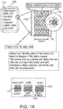
- FIG. 1A is a diagram of a safe apparatus 100, according to an example embodiment, according to an example embodiment. It is to be noted that the components are shown schematically in greatly simplified form, with only those components relevant to understanding of the embodiments being illustrated.
- the safe apparatus 100 includes a safe door 110 and the safe door includes: an externally facing solid surface 113 (the surface visible to an onlooker when the safe door 110 is closed), an internally facing solid surface 114 (the surface visible when the safe door 110 is opened and the surface on the interior of the safe door), a gap 112 between the externally facing surface 113 and the internally facing surface 114, and a weaved fabric material 111 inserted in the gap 112.
- the weaved fabric material 111 is designed to bunch around a drill bit or drilling tool when the externally facing surface 113 is penetrated by the drilling tool so as to impeded progress of the drilling tool to reach the internally facing surface 114 or progress through the internally facing surface 114 to reach the interior of the safe 100.
- the circular graphic in the FIG. 1A illustrates how the attack tool becomes tangled in the fabric 111 with the fabric 111 bunching up around the attack tool.
- the graphic at the bottom of the FIG. 1A illustrates a variety of types of weaves that can be deployed for the fabric 111, such as a wart and weft woven fabric 111, a weft knitted fabric 111, and a warp knitted fabric 111. It is noted that other types of woven fabric patterns can be used without departing from the novel aspects of the presented safe 100.
- the gap 112 between the externally facing surface 113 and the internally facing surface 114 is approximately 10 mm. Again, it is noted that other sizes of the gap 112 can be deployed without departing from novel aspects of the presented safe 100.
- the gap 112 and the inserted fabric 111 surrounds all six sides of the safe 100; rather than just the door 110, such that the externally facing surface 113 and the internally facing surface 114 with the gap 112 and the fabric 111 surround all size sides of the safe 100.
- the externally facing surface 113 and the internally facing surface 114 are constructed of a single solid material, such as hard plastic.
- a thin portion of the externally facing surface 113 is constructed of steel while a remaining portion of the externally facing surface 113 is a hard plastic.
- a thin portion of the internally facing surface 114 is constructed of steel while a remaining portion or the internally facing surface 114 is a hard plastic.
- both or just one of the externally facing surface 113 and the internally facing surface 114 are constructed of solid steel.
- the safe 100 and the safe door 110 is constructed of hard plastic with rounded edges.
- POS Point-Of-Sale
- SST Self-Service Terminal
- ATM Automated Teller Machine
- the gap 112 manufacture between the externally facing surface 113 and the internally facing surface 114 allows the safe 100 to be lighter than conventional all solid steel constructed safes, which also improves safe transport and installation.
- the fabric 111 is made of foam. In an embodiment, portions of the woven fabric 111 are constructed of a first material while other portions of the woven fabric 111 are constructed of a second and different material. In an embodiment, all or a portion of the fabric 111 is made of Kevlar®.
- the entire six sides of the safe can be constructed in the presented manner or just the safe door 110.
- the presented safe 100 also reduces the conventional cost of manufacturing the safe 100 because conventional safes are constructed of solid steel walls with no gaps and steel is expensive relative to a low cost fabric 111 with a safe 100 that includes less steel or is devoid of steel entirely (as discussed above in the various presented embodiments).
- the presented embodiments of the safe 100 are substantially lighter and less expensive to manufacture than conventional safe construction while at the same time, the presented safe 100 increases safe protection and security by thwarting or substantially impeding penetration into the interior of the safe 100 through the fabric 111 protection mechanism.
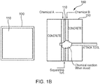
- FIG. 1B is a diagram of another safe apparatus 100, according to an example embodiment.
- the gap 112 includes a separating film that segments the gap 112 into two separate compartments.
- Each compartment includes a different chemical mixture, such that when an attack tool penetrates the film the two separate chemical mixtures release and mix with one another. This creates a chemical reaction that produces a solid in short period of time to impeded or thwart the attach tool from reaching the internally facing surface 114 of the safe 100.
- the entire gap 112 includes both chemical A and B and the separating film.
- the gap can also include two layers of concrete thick enough to impede (slow down) or damage the attack tool during cutting of the safe 100.
- the gap 112 then includes a first layer of concrete followed by chemical A followed by a thin separating film followed by chemical B and a second layer of concrete.
- the two separate chemicals or chemical mixtures A and B when mixed and interacted with one another produce a self-hardening by product (such as a hardening and quick setting foam).
- a plurality of chemical mixture can achieve this end, such as Alumilite Rigid Foams®, mixing Polyurethane foam liquids, etc.
- the chemical mixture there is a single chemical mixture that is inserted in the gap 112 under pressure, such that when the pressure is eased through a penetration into the gap, the chemical mixture hardens into a hard foam, such as 3M Polystyrene Foam®, Tiger Foam®, etc.
- a hard foam such as 3M Polystyrene Foam®, Tiger Foam®, etc.
- the chemical mixture is a mixture that rapidly hardens when pressure is eased and/or when exposed to air.
- FIG. 1A illustrates a woven fabric in a gap 112 of safe 100 walls to impeded an attack tool from penetrating the interior of a safe 100.
- FIG. 1B illustrates one or more chemicals that when mixed or when pressure is eased or exposed to air produces a rapidly setting hardened foam that impedes an attack tool from penetrating the interior of a safe.
- the gap 112 can be included in the manufacture of just the safe door 110 or the entire six side walls of the safe 100.
- the embodiments presented provides improved safes 100 that are lighter than conventional safes and less expensive to manufacture.
- the improved safes 100 also provide improved safe protection from attack tools attempting to penetrate into the interior of the safe 100.
- FIGS. 2-4 These and other embodiments are now discussed with reference to the FIGS. 2-4 .
- FIG. 2 is a diagram of a safe apparatus 200.
- the safe apparatus 200 referred to herein as just "safe 200.”
- the safe 200 is the safe 100 of the FIG. 1A .
- the safe 200 is the safe 100 of the FIG. 1B .
- the safe 200 includes six walls or surfaces having an interior compartment for which valuables are maintained, such as currency and the like.
- the safe 200 also includes a safe door 210.
- At least one wall of the safe is manufactured with a solid externally facing surface 211 and a solid internally facing surface 212.
- the externally facing surface 211 separated from the internally facing surface 212 by a gap 213 and inserted into the gap 213 is a safe protection mechanism 214, 215, and/or 216.
- the gap 213 with the safe protection mechanism 214, 215, and/or 216 is approximately 10 millimeters in thickness.
- the gap 213 creates an interior chamber within the at least one wall. Inserted into the chamber is the safe protection mechanism 214, 215, and/or 216.
- the walls are constructed of a hard plastic material.
- the at least one wall is the wall of the safe door 210.
- the at least one wall is all six walls or surfaces of the safe 200.
- the safe protection mechanism is a woven fabric 214 as discussed above with the discussion and illustration of the FIG. 1A and the fabric 111.
- the safe protection mechanism includes a thin film 215 and a first chemical 214 and a second chemical 216.
- the film 215 when penetrated by an attack tool ruptures and causes the two chemicals 214 and 216 to mix with one another or interact with one another forming a hard and quick setting foam around a site that the film 215 was penetrated or ruptured.
- the safe protection mechanism includes a single chemical 214 or 215 that is under pressure, such that when the externally facing surface 211 of the at least one wall is penetrated by an attack tool, pressure is eased and air mixes with the chemical 214 or 215, which induces a quick setting hard foam byproduct around a site where the externally facing surface 211 was penetrated in order to thwart or impeded the progress of an attack tool.
- the externally facing surface 211 is constructed of a first solid material and the internally facing surface 212 is construed of a second solid material that is different from the first solid material.
- the externally facing surface 211 and the internally facing surface 212 are constructed of a same solid material.
- the gap 215 includes a first portion abutting the externally facing surface 211 filled with concrete and the gap 215 includes a second portion abutting the internally facing surface 212 filled with concrete.
- the gap 215 also includes the safe protection mechanism 215, 215, and/or 216 between the first and second portions.
- FIG. 3 is a diagram of a method 300 for safe protection, according to an example embodiment.
- the method 300 representing a method of manufacturing the safe 100 of the FIGS. 1A and 1B and the safe 200 of the FIG. 2 .
- At 310 at least one wall of the six walls or surfaces of the safe is formed with a gap, such that the at least one wall includes an interior chamber that separates an externally facing surface of the at least one wall and an internally facing surface of the at least one wall.
- the gap is formed in all size walls or surfaces of the safe.
- the gap is formed in a safe door of the safe.
- the gap is manufactured with an embedded safe protection mechanism that is activated with the externally facing surface is penetrated with an attack tool to thwart or impede penetration into an interior of the safe.
- a woven fabric is inserted into the gap as the safe protection mechanism.
- a thin film is inserted into a center of the gap and two chemicals are inserted on each side of the thin film.
- the thin film when penetrated mix the two chemicals and form a hard foam that impedes the progress of the attack tool.
- the thin film and the two chemicals combine to form the safe protection mechanism.
- a chemical mixture under pressure is inserted within the gap and when the externally facing surface is penetrated, the pressure is eased and air interacts with the chemical mixture inducing a hard foam that impedes progress of the attack tool.
- the chemical mixture under pressure within the gap is the safe protection mechanism.
- FIG. 4 is a diagram of another method 400 for safe protection, according to an example embodiment.
- the method 400 is a combined method of manufacture and installation of the safe 100 of the FIGS. 1A and 1B and the safe 200 of the FIG. 2 .
- the method 400 includes all of or some combination of the method 300.
- a safe is manufactured with at least one wall of six walls or surfaces to include a gap and a safe protection mechanism is inserted into the gap to thwart or impeded progress of a safe attack.
- the safe protection mechanism is one of: a woven fabric, a thin film having two different chemicals separated by the thin film that when mixed together produce a hard foam, and a chemical mixture under pressure that when pressure is eased and air interact with the chemical mixture a hard foam is produced.
Landscapes
- Engineering & Computer Science (AREA)
- Textile Engineering (AREA)
- Treatments For Attaching Organic Compounds To Fibrous Goods (AREA)
- Casting Or Compression Moulding Of Plastics Or The Like (AREA)
- Woven Fabrics (AREA)
- Laminated Bodies (AREA)
- Buffer Packaging (AREA)
Abstract
Description
- Existing high security safes use steel reinforcement to add strength to the safes and increase the needed safe attack times. Steel adds substantial manufacturing costs and increases the weight of the safes making transport and installation of the safes more difficult.
- In various embodiments, methods and apparatuses for enhanced safe protection are presented.
- According to an embodiment, a safe apparatus is presented. Specifically, and in an embodiment, the safe apparatus includes walls and at least one wall includes a gap, inserted into the gap is a safe protection mechanism that thwarts and/or impedes a safe attack on the safe.
- Acorrding to a first aspect of the present invention there is provided a safe, comprising: walls; and at least one of the walls including a gap and the gap including a safe protection mechanism.
- Optionally, the walls may be constructed of hard plastic.
- Optionally, the at least one wall may include an externally facing surface constructed of a solid material and an internally facing surface constructed of the solid material, the externally facing surface separated from the internally facing surface by the gap and the safe protection mechanism.
- Optionally, the at least one wall may include all of the walls.
- Optionally, the at least one wall may include a safe door for the safe.
- Optionally, the safe protection mechanism may be a woven fabric.
- Optionally, the safe protection mechanism may include a thin film that separates two chemicals, and the thin film when penetrated causes the two chemicals to mix together as a mixture, and the mixture configured to form a hard foam around a site that the film was penetrated.
- Optionally, the safe protection mechanism may include a chemical mixture under pressure, and when the externally facing surface may be penetrated pressure may be eased and air penetrates the chemical mixture forming a hard foam around a site that the externally facing surface was penetrated.
- Optionally, the externally facing surface may be constructed of a first solid material and the internally facing surface may be construed of a second solid material that may be different from the first solid material.
- Optionally, the externally facing surface and the internally facing surface may be construed a same solid material.
- Optionally, the gap may include a first portion abutting the externally facing surface filled with concrete, and the gap may include a second portion abutting the internally facing surface filled with concrete.
- According to a second aspect of the present invention there is provided a method comprising: forming at least one wall of a safe with a gap; and manufacturing within the gap a safe protection mechanism that may be activated when an externally facing surface of the at least one wall may be penetrated with an attack tool to thwart or impeded penetration into an interior of the safe.
- Optionally, forming may further include forming the gap in all walls of the safe.
- Optionally, forming may further include forming the gap in a safe door of the safe.
- Optionally, manufacturing may further include inserting a woven fabric into the gap as the safe protection mechanism.
- Optionally, manufacturing may further include inserting a thin film in a center of the gap and inserting two chemicals on each side of the thin film, and when the thin film may be penetrated mixing the two chemicals forming a hard foam that impedes progress of the attack tool, wherein the thin film and the two chemicals combine form the safe protection mechanism.
- Optionally, manufacturing may further include inserting a chemical mixture under pressure within the gap, and when the externally facing surface may be penetrated causing pressure to ease and air to interact with the chemical mixture a hard foam may be induced that impedes progress of the attack tool, wherein the chemical mixture under pressure may be the safe protection mechanism.
- According to a third aspect of the present invention, there is provided a method comprising: manufacturing a safe having at least one wall that may include a gap and inserted into the gap a safe protection mechanism to thwart or impeded a safe attack; and integrating the safe into a Self-Service Terminal (SST) as a portion of the SST and used during operation of the SST.
- Optionally, the SST may be one of: an Automated Teller Machine (ATM) and a kiosk.
- Optionally, the safe protection mechanism may be one of: woven fabric; a thin film having two different chemicals separated by the thin film that when mixed together produce a hard foam; and a chemical mixture under pressure that when pressure may be eased and air interacts with the chemical mixture a hard foam may be produced.
- These and other aspects of the present invention will be apparent form the following specific description, given by way of example, with reference to the accompanying drawings.
-
FIG. 1A is a diagram of a safe apparatus, according to an example embodiment. -
FIG. 1B is a diagram of another safe apparatus, according to an example embodiment. -
FIG. 2 is a diagram of a safe apparatus, according to an example embodiment. -
FIG. 3 is a diagram of a method for protecting a safe, according to an example embodiment. -
FIG. 4 is a diagram of another method for protecting a safe, according to an example embodiment. -
FIG. 1A is a diagram of asafe apparatus 100, according to an example embodiment, according to an example embodiment. It is to be noted that the components are shown schematically in greatly simplified form, with only those components relevant to understanding of the embodiments being illustrated. - Furthermore, the various components (that are identified in the
FIG. 1 ) are illustrated and the arrangement of the components is presented for purposes of illustration only. It is to be noted that other arrangements with more or less components are possible without departing from the teachings of safe protection, presented herein and below. - The safe apparatus 100 (hereinafter safe 100) includes a
safe door 110 and the safe door includes: an externally facing solid surface 113 (the surface visible to an onlooker when thesafe door 110 is closed), an internally facing solid surface 114 (the surface visible when thesafe door 110 is opened and the surface on the interior of the safe door), agap 112 between the externally facingsurface 113 and the internally facingsurface 114, and a weavedfabric material 111 inserted in thegap 112. - The weaved
fabric material 111 is designed to bunch around a drill bit or drilling tool when the externally facingsurface 113 is penetrated by the drilling tool so as to impeded progress of the drilling tool to reach the internally facingsurface 114 or progress through the internally facingsurface 114 to reach the interior of the safe 100. The circular graphic in theFIG. 1A illustrates how the attack tool becomes tangled in thefabric 111 with thefabric 111 bunching up around the attack tool. - The graphic at the bottom of the
FIG. 1A illustrates a variety of types of weaves that can be deployed for thefabric 111, such as a wart andweft woven fabric 111, a weft knittedfabric 111, and a warp knittedfabric 111. It is noted that other types of woven fabric patterns can be used without departing from the novel aspects of the presented safe 100. - In an embodiment, the
gap 112 between the externally facingsurface 113 and the internally facingsurface 114 is approximately 10 mm. Again, it is noted that other sizes of thegap 112 can be deployed without departing from novel aspects of the presented safe 100. - In an embodiment, the
gap 112 and the insertedfabric 111 surrounds all six sides of the safe 100; rather than just thedoor 110, such that the externally facingsurface 113 and the internally facingsurface 114 with thegap 112 and thefabric 111 surround all size sides of the safe 100. - In an embodiment, the externally facing
surface 113 and the internally facingsurface 114 are constructed of a single solid material, such as hard plastic. - In an embodiment, a thin portion of the externally facing
surface 113 is constructed of steel while a remaining portion of the externally facingsurface 113 is a hard plastic. - In an embodiment, a thin portion of the internally facing
surface 114 is constructed of steel while a remaining portion or the internally facingsurface 114 is a hard plastic. - In an embodiment, both or just one of the externally facing
surface 113 and the internally facingsurface 114 are constructed of solid steel. - In an embodiment, the safe 100 and the
safe door 110 is constructed of hard plastic with rounded edges. - Uses of plastic for the entire safe 100 or just some portions of the safe 100 as discussed above makes the safe 100 lighter than
conventional safes 100, which means there is an improved ability to transport and install the safe in a Point-Of-Sale (POS) terminal or a Self-Service Terminal (SST), such as an Automated Teller Machine (ATM) or a kiosk. - Moreover, the
gap 112 manufacture between the externally facingsurface 113 and the internally facingsurface 114 allows the safe 100 to be lighter than conventional all solid steel constructed safes, which also improves safe transport and installation. - In an embodiment, the
fabric 111 is made of foam. In an embodiment, portions of thewoven fabric 111 are constructed of a first material while other portions of thewoven fabric 111 are constructed of a second and different material. In an embodiment, all or a portion of thefabric 111 is made of Kevlar®. - Again, the entire six sides of the safe can be constructed in the presented manner or just the
safe door 110. - The presented safe 100 also reduces the conventional cost of manufacturing the safe 100 because conventional safes are constructed of solid steel walls with no gaps and steel is expensive relative to a
low cost fabric 111 with a safe 100 that includes less steel or is devoid of steel entirely (as discussed above in the various presented embodiments). - Additionally, the presented embodiments of the safe 100 are substantially lighter and less expensive to manufacture than conventional safe construction while at the same time, the presented safe 100 increases safe protection and security by thwarting or substantially impeding penetration into the interior of the safe 100 through the
fabric 111 protection mechanism. -
FIG. 1B is a diagram of anothersafe apparatus 100, according to an example embodiment. - The embodiment presented in the
FIG. 1B differs from the embodiment presented in theFIG. 1A in a few ways. Notably, thegap 112 includes a separating film that segments thegap 112 into two separate compartments. Each compartment includes a different chemical mixture, such that when an attack tool penetrates the film the two separate chemical mixtures release and mix with one another. This creates a chemical reaction that produces a solid in short period of time to impeded or thwart the attach tool from reaching the internally facingsurface 114 of the safe 100. Theentire gap 112 includes both chemical A and B and the separating film. - In an embodiment, as illustrated in the
FIG. 1B , the gap can also include two layers of concrete thick enough to impede (slow down) or damage the attack tool during cutting of the safe 100. Thegap 112 then includes a first layer of concrete followed by chemical A followed by a thin separating film followed by chemical B and a second layer of concrete. - In an embodiment, the two separate chemicals or chemical mixtures A and B when mixed and interacted with one another produce a self-hardening by product (such as a hardening and quick setting foam). A plurality of chemical mixture can achieve this end, such as Alumilite Rigid Foams®, mixing Polyurethane foam liquids, etc.
- In an embodiment, there is a single chemical mixture that is inserted in the
gap 112 under pressure, such that when the pressure is eased through a penetration into the gap, the chemical mixture hardens into a hard foam, such as 3M Polystyrene Foam®, Tiger Foam®, etc. In this embodiment, there is no film in the gap and the chemical mixture is a mixture that rapidly hardens when pressure is eased and/or when exposed to air. -
FIG. 1A illustrates a woven fabric in agap 112 of safe 100 walls to impeded an attack tool from penetrating the interior of a safe 100.FIG. 1B illustrates one or more chemicals that when mixed or when pressure is eased or exposed to air produces a rapidly setting hardened foam that impedes an attack tool from penetrating the interior of a safe. Thegap 112 can be included in the manufacture of just thesafe door 110 or the entire six side walls of the safe 100. - The embodiments presented provides
improved safes 100 that are lighter than conventional safes and less expensive to manufacture. Theimproved safes 100 also provide improved safe protection from attack tools attempting to penetrate into the interior of the safe 100. - These and other embodiments are now discussed with reference to the
FIGS. 2-4 . -
FIG. 2 is a diagram of asafe apparatus 200. Thesafe apparatus 200 referred to herein as just "safe 200." - In an embodiment, the safe 200 is the safe 100 of the
FIG. 1A . - In an embodiment, the safe 200 is the safe 100 of the
FIG. 1B . - The safe 200 includes six walls or surfaces having an interior compartment for which valuables are maintained, such as currency and the like.
- The safe 200 also includes a
safe door 210. - At least one wall of the safe is manufactured with a solid externally facing
surface 211 and a solid internally facingsurface 212. The externally facingsurface 211 separated from the internally facingsurface 212 by agap 213 and inserted into thegap 213 is asafe protection mechanism - In an embodiment, the
gap 213 with thesafe protection mechanism gap 213 creates an interior chamber within the at least one wall. Inserted into the chamber is thesafe protection mechanism - In an embodiment, the walls are constructed of a hard plastic material.
- In an embodiment, the at least one wall is the wall of the
safe door 210. - In an embodiment, the at least one wall is all six walls or surfaces of the safe 200.
- In an embodiment, the safe protection mechanism is a
woven fabric 214 as discussed above with the discussion and illustration of theFIG. 1A and thefabric 111. - In an embodiment, the safe protection mechanism includes a
thin film 215 and afirst chemical 214 and asecond chemical 216. Thefilm 215 when penetrated by an attack tool ruptures and causes the twochemicals film 215 was penetrated or ruptured. - In an embodiment, the safe protection mechanism includes a
single chemical surface 211 of the at least one wall is penetrated by an attack tool, pressure is eased and air mixes with the chemical 214 or 215, which induces a quick setting hard foam byproduct around a site where the externally facingsurface 211 was penetrated in order to thwart or impeded the progress of an attack tool. - In an embodiment, the externally facing
surface 211 is constructed of a first solid material and the internally facingsurface 212 is construed of a second solid material that is different from the first solid material. - In an embodiment, the externally facing
surface 211 and the internally facingsurface 212 are constructed of a same solid material. - In an embodiment, the
gap 215 includes a first portion abutting the externally facingsurface 211 filled with concrete and thegap 215 includes a second portion abutting the internally facingsurface 212 filled with concrete. Thegap 215 also includes thesafe protection mechanism -
FIG. 3 is a diagram of amethod 300 for safe protection, according to an example embodiment. - The
method 300 representing a method of manufacturing the safe 100 of theFIGS. 1A and1B and the safe 200 of theFIG. 2 . - At 310, at least one wall of the six walls or surfaces of the safe is formed with a gap, such that the at least one wall includes an interior chamber that separates an externally facing surface of the at least one wall and an internally facing surface of the at least one wall.
- According to an embodiment, at 311, the gap is formed in all size walls or surfaces of the safe.
- In an embodiment at 312, the gap is formed in a safe door of the safe.
- At 320, the gap is manufactured with an embedded safe protection mechanism that is activated with the externally facing surface is penetrated with an attack tool to thwart or impede penetration into an interior of the safe.
- In an embodiment, at 321, a woven fabric is inserted into the gap as the safe protection mechanism.
- In an embodiment, at 322, a thin film is inserted into a center of the gap and two chemicals are inserted on each side of the thin film. The thin film when penetrated mix the two chemicals and form a hard foam that impedes the progress of the attack tool. The thin film and the two chemicals combine to form the safe protection mechanism.
- In an embodiment, at 323, a chemical mixture under pressure is inserted within the gap and when the externally facing surface is penetrated, the pressure is eased and air interacts with the chemical mixture inducing a hard foam that impedes progress of the attack tool. The chemical mixture under pressure within the gap is the safe protection mechanism.
-
FIG. 4 is a diagram of anothermethod 400 for safe protection, according to an example embodiment. - The
method 400 is a combined method of manufacture and installation of the safe 100 of theFIGS. 1A and1B and the safe 200 of theFIG. 2 . - In an embodiment, the
method 400 includes all of or some combination of themethod 300. - At 410, a safe is manufactured with at least one wall of six walls or surfaces to include a gap and a safe protection mechanism is inserted into the gap to thwart or impeded progress of a safe attack.
- In an embodiment, at 411, the safe protection mechanism is one of: a woven fabric, a thin film having two different chemicals separated by the thin film that when mixed together produce a hard foam, and a chemical mixture under pressure that when pressure is eased and air interact with the chemical mixture a hard foam is produced.
- The above description is illustrative, and not restrictive. Many other embodiments will be apparent to those of skill in the art upon reviewing the above description. The scope of embodiments should therefore be determined with reference to the appended claims, along with the full scope of equivalents to which such claims are entitled.
- In the foregoing description of the embodiments, various features are grouped together in a single embodiment for the purpose of streamlining the disclosure. This method of disclosure is not to be interpreted as reflecting that the claimed embodiments have more features than are expressly recited in each claim. Rather, as the following claims reflect, inventive subject matter lies in less than all features of a single disclosed embodiment.
Claims (14)
- A safe (100), comprising:walls; andat least one of the walls including a gap (112) and the gap including a safe protection mechanism (111, 214, 215, and/or 216).
- The safe of claim 1, wherein the walls are constructed of hard plastic.
- The safe according to any previous claim, wherein the at least one wall includes an externally facing surface (113) constructed of a solid material and an internally facing surface (114) constructed of the solid material, the externally facing surface separated from the internally facing surface by the gap and the safe protection mechanism.
- The safe of claim 3, wherein the at least one wall includes all of the walls.
- The safe of claim 3, wherein the at least one wall includes a safe door (110) for the safe.
- The safe of claim 3, wherein the safe protection mechanism is a woven fabric (111).
- The safe of claim 3, wherein the safe protection mechanism includes a thin film (215) that separates two chemicals (214, 216), and the thin film when penetrated causes the two chemicals to mix together as a mixture, and the mixture configured to form a hard foam around a site that the film was penetrated.
- The safe of claim 3, wherein the safe protection mechanism includes a chemical mixture under pressure, and when the externally facing surface is penetrated pressure is eased and air penetrates the chemical mixture forming a hard foam around a site that the externally facing surface was penetrated.
- The safe of claim 3, wherein the externally facing surface is constructed of a first solid material and the internally facing surface is construed of a second solid material that is different from the first solid material.
- The safe of claim 3, wherein the externally facing surface and the internally facing surface are construed a same solid material.
- The safe of claim 3, wherein the gap includes a first portion abutting the externally facing surface filled with concrete, and the gap includes a second portion abutting the internally facing surface filled with concrete.
- A method, comprising:manufacturing a safe having at least one wall that includes a gap and inserted into the gap a safe protection mechanism to thwart or impeded a safe attack (410); andintegrating the safe into a Self-Service Terminal (SST) as a portion of the SST and used during operation of the SST (420).
- The method of claim 12, wherein the SST is one of: an Automated Teller Machine (ATM) and a kiosk (421).
- The method according to any preceding claim, wherein the safe protection mechanism is one of (411):woven fabric;a thin film having two different chemicals separated by the thin film that when mixed together produce a hard foam; anda chemical mixture under pressure that when pressure is eased and air interacts with the chemical mixture a hard foam is produced.
Applications Claiming Priority (1)
| Application Number | Priority Date | Filing Date | Title |
|---|---|---|---|
| US15/608,897 US10378267B2 (en) | 2017-05-30 | 2017-05-30 | Safe protection apparatuses and methods |
Publications (2)
| Publication Number | Publication Date |
|---|---|
| EP3409871A1 true EP3409871A1 (en) | 2018-12-05 |
| EP3409871B1 EP3409871B1 (en) | 2021-04-14 |
Family
ID=62186276
Family Applications (1)
| Application Number | Title | Priority Date | Filing Date |
|---|---|---|---|
| EP18172454.3A Active EP3409871B1 (en) | 2017-05-30 | 2018-05-15 | Safe protection apparatuses and methods |
Country Status (3)
| Country | Link |
|---|---|
| US (1) | US10378267B2 (en) |
| EP (1) | EP3409871B1 (en) |
| CN (2) | CN108979448A (en) |
Families Citing this family (2)
| Publication number | Priority date | Publication date | Assignee | Title |
|---|---|---|---|---|
| EP3477038B1 (en) * | 2017-10-24 | 2019-12-11 | Assa Abloy AB | Drill protection device, drill protection assembly and access member |
| SE543721C2 (en) * | 2019-01-04 | 2021-06-29 | Cesium Ab | Upper construction element and lower construction element for a container and a container |
Citations (4)
| Publication number | Priority date | Publication date | Assignee | Title |
|---|---|---|---|---|
| US1567707A (en) * | 1920-08-19 | 1925-12-29 | Art Metal Construction Co | Safe |
| EP0633381A1 (en) * | 1993-07-05 | 1995-01-11 | OTTO LAMPERTZ FABRIKEN FÜR ORGANISATIONSMITTEL UND EDV-ZUBEHÖR GmbH & Co. KG | A composite wall element for the construction of spaces, lockers, safes and similar security devices protected against fire, water and burglary |
| WO2014076223A1 (en) * | 2012-11-16 | 2014-05-22 | Döttling Markus | Portable security container |
| WO2015200932A2 (en) * | 2014-05-28 | 2015-12-30 | Magneto Ip Holdings (Pty) Ltd | Protection of a safe |
Family Cites Families (18)
| Publication number | Priority date | Publication date | Assignee | Title |
|---|---|---|---|---|
| US4662288A (en) * | 1978-06-05 | 1987-05-05 | Transaction Security, Inc. | Insulating apparatus and burglary resistant composite laminates employed therein |
| DE2931330A1 (en) * | 1979-08-02 | 1981-02-26 | Distelrath Gmbh | STEEL CABINET, SAFE OR THE LIKE |
| US4263365A (en) * | 1979-08-02 | 1981-04-21 | John D. Brush & Co., Inc. | Fire-resistant safe and panel |
| GB8400990D0 (en) * | 1984-01-14 | 1984-02-15 | Chubb & Sons Lock & Safe Co | Fireresistant enclosures |
| JPS61254781A (en) * | 1985-04-30 | 1986-11-12 | 株式会社イトーキクレビオ | Cdre material for safe, etc. |
| US5069358A (en) * | 1991-01-03 | 1991-12-03 | John D. Brush & Co., Inc. | Media case |
| US5152231A (en) * | 1991-01-30 | 1992-10-06 | John D. Brush & Co., Inc. | Fire-resistant safe |
| US6841209B2 (en) * | 2000-01-12 | 2005-01-11 | Fireking International, Inc. | Fire protection containers incorporating novel low free-water insulation materials |
| JP4675328B2 (en) * | 2003-11-03 | 2011-04-20 | ナムローゼ・フェンノートシャップ・ベーカート・ソシエテ・アノニム | Blade-proof insert with steel cord and non-woven fabric |
| US8327778B2 (en) * | 2009-10-28 | 2012-12-11 | Dellorusso Jr Anthony J | Light weight portable fire resistant containment system |
| US8474386B2 (en) * | 2009-10-28 | 2013-07-02 | Anthony J. DelloRusso, JR. | Fire resistant containment system having a light weight portable removable enclosure |
| JP5474502B2 (en) * | 2009-11-18 | 2014-04-16 | 沖電気工業株式会社 | Enclosure |
| US8567665B2 (en) * | 2010-05-20 | 2013-10-29 | Ncr Corporation | Secure enclosure |
| US9582972B2 (en) * | 2011-01-20 | 2017-02-28 | Tecnologia Bancaria S.A. | Method for bank equipment reinforcement and fixation through an anchorage base |
| CN202509946U (en) * | 2011-12-05 | 2012-10-31 | 创斯达(南通)机电有限公司 | Chemical protection layers embedded in safety box body |
| SE537876C2 (en) * | 2012-10-11 | 2015-11-10 | Engtex Ab | Anti-intrusion arrangements |
| US9333714B2 (en) * | 2013-01-16 | 2016-05-10 | Hardwire, Llc | Vehicular armor system |
| CN203905713U (en) * | 2014-05-29 | 2014-10-29 | 焦作市九龙聚海工贸有限公司 | Bullet bin for arms locker and with fireproof alarm function |
-
2017
- 2017-05-30 US US15/608,897 patent/US10378267B2/en active Active
-
2018
- 2018-05-07 CN CN201810424785.3A patent/CN108979448A/en active Pending
- 2018-05-07 CN CN202310647932.4A patent/CN116696203A/en active Pending
- 2018-05-15 EP EP18172454.3A patent/EP3409871B1/en active Active
Patent Citations (4)
| Publication number | Priority date | Publication date | Assignee | Title |
|---|---|---|---|---|
| US1567707A (en) * | 1920-08-19 | 1925-12-29 | Art Metal Construction Co | Safe |
| EP0633381A1 (en) * | 1993-07-05 | 1995-01-11 | OTTO LAMPERTZ FABRIKEN FÜR ORGANISATIONSMITTEL UND EDV-ZUBEHÖR GmbH & Co. KG | A composite wall element for the construction of spaces, lockers, safes and similar security devices protected against fire, water and burglary |
| WO2014076223A1 (en) * | 2012-11-16 | 2014-05-22 | Döttling Markus | Portable security container |
| WO2015200932A2 (en) * | 2014-05-28 | 2015-12-30 | Magneto Ip Holdings (Pty) Ltd | Protection of a safe |
Also Published As
| Publication number | Publication date |
|---|---|
| CN116696203A (en) | 2023-09-05 |
| US10378267B2 (en) | 2019-08-13 |
| US20180347255A1 (en) | 2018-12-06 |
| CN108979448A (en) | 2018-12-11 |
| EP3409871B1 (en) | 2021-04-14 |
Similar Documents
| Publication | Publication Date | Title |
|---|---|---|
| US10378267B2 (en) | Safe protection apparatuses and methods | |
| EP1955005B1 (en) | Protective structure and protective system | |
| KR101612434B1 (en) | Rock Blasting Method for using Minerals | |
| KR20160004892A (en) | PBD complex equipment installed beforehand boring structure with vibratory-hammer/breaker and system/method thereof | |
| KR100554944B1 (en) | Tunnel Rock Excavation Excavation Study Minimization Blasting Method | |
| KR20180110888A (en) | Construction methods of approaching dual tunnel | |
| RU2433267C1 (en) | Method of ore deposits mining by sublevel caving | |
| JP2019027011A (en) | Reinforcement anchor | |
| KR101696409B1 (en) | Paten using location difference of detonator explosive, and method for blasting | |
| JP6868437B2 (en) | How to hang the surface of a concrete skeleton to a predetermined depth | |
| KR101185325B1 (en) | An outer wall structure of a safe and manufacturing method thereof | |
| JP5297018B2 (en) | Storage warehouse | |
| WO2015200932A2 (en) | Protection of a safe | |
| US20060225376A1 (en) | Reinforcement assembly for matrix materials | |
| EP2496773A1 (en) | Improved slope of an open cut mine | |
| EP2365177A2 (en) | An armoured panel for a secure enclosure | |
| EP1871956A1 (en) | Masonry block | |
| KR20170008418A (en) | PBD complex equipment installed beforehand boring structure with vibratory-hammer/breaker and system/method thereof | |
| JP3373429B2 (en) | Ground improvement method | |
| Li et al. | Rock fracturing related to strain burst in quartzite rock mass | |
| WO2019224669A1 (en) | Safety device against deflagration or detonation of explosive devices for automated teller machines,protected automated teller machine and method of protection of a confined environment from deflagration or detonation, by means of an explosive device, of an automated teller machine | |
| BRPI1003775A2 (en) | abrasive coating for atm safes internal and external protection system | |
| PL441611A1 (en) | Method of isolating the goafs of a wall being demolished and sealing agent for isolating the goafs | |
| JP6910120B2 (en) | Composite vein-shaped ground improvement method | |
| JP2023119345A (en) | SOIL IMPROVEMENT DEVICE AND SOIL IMPROVEMENT METHOD |
Legal Events
| Date | Code | Title | Description |
|---|---|---|---|
| PUAI | Public reference made under article 153(3) epc to a published international application that has entered the european phase |
Free format text: ORIGINAL CODE: 0009012 |
|
| STAA | Information on the status of an ep patent application or granted ep patent |
Free format text: STATUS: THE APPLICATION HAS BEEN PUBLISHED |
|
| AK | Designated contracting states |
Kind code of ref document: A1 Designated state(s): AL AT BE BG CH CY CZ DE DK EE ES FI FR GB GR HR HU IE IS IT LI LT LU LV MC MK MT NL NO PL PT RO RS SE SI SK SM TR |
|
| AX | Request for extension of the european patent |
Extension state: BA ME |
|
| STAA | Information on the status of an ep patent application or granted ep patent |
Free format text: STATUS: REQUEST FOR EXAMINATION WAS MADE |
|
| 17P | Request for examination filed |
Effective date: 20190605 |
|
| RBV | Designated contracting states (corrected) |
Designated state(s): AL AT BE BG CH CY CZ DE DK EE ES FI FR GB GR HR HU IE IS IT LI LT LU LV MC MK MT NL NO PL PT RO RS SE SI SK SM TR |
|
| STAA | Information on the status of an ep patent application or granted ep patent |
Free format text: STATUS: EXAMINATION IS IN PROGRESS |
|
| 17Q | First examination report despatched |
Effective date: 20191118 |
|
| GRAP | Despatch of communication of intention to grant a patent |
Free format text: ORIGINAL CODE: EPIDOSNIGR1 |
|
| STAA | Information on the status of an ep patent application or granted ep patent |
Free format text: STATUS: GRANT OF PATENT IS INTENDED |
|
| INTG | Intention to grant announced |
Effective date: 20201210 |
|
| GRAS | Grant fee paid |
Free format text: ORIGINAL CODE: EPIDOSNIGR3 |
|
| GRAA | (expected) grant |
Free format text: ORIGINAL CODE: 0009210 |
|
| STAA | Information on the status of an ep patent application or granted ep patent |
Free format text: STATUS: THE PATENT HAS BEEN GRANTED |
|
| AK | Designated contracting states |
Kind code of ref document: B1 Designated state(s): AL AT BE BG CH CY CZ DE DK EE ES FI FR GB GR HR HU IE IS IT LI LT LU LV MC MK MT NL NO PL PT RO RS SE SI SK SM TR |
|
| REG | Reference to a national code |
Ref country code: GB Ref legal event code: FG4D |
|
| REG | Reference to a national code |
Ref country code: CH Ref legal event code: EP |
|
| REG | Reference to a national code |
Ref country code: DE Ref legal event code: R084 Ref document number: 602018015407 Country of ref document: DE |
|
| REG | Reference to a national code |
Ref country code: DE Ref legal event code: R096 Ref document number: 602018015407 Country of ref document: DE |
|
| REG | Reference to a national code |
Ref country code: IE Ref legal event code: FG4D Ref country code: GB Ref legal event code: 746 Effective date: 20210421 |
|
| REG | Reference to a national code |
Ref country code: AT Ref legal event code: REF Ref document number: 1382524 Country of ref document: AT Kind code of ref document: T Effective date: 20210515 |
|
| REG | Reference to a national code |
Ref country code: LT Ref legal event code: MG9D |
|
| REG | Reference to a national code |
Ref country code: AT Ref legal event code: MK05 Ref document number: 1382524 Country of ref document: AT Kind code of ref document: T Effective date: 20210414 |
|
| REG | Reference to a national code |
Ref country code: NL Ref legal event code: MP Effective date: 20210414 |
|
| PG25 | Lapsed in a contracting state [announced via postgrant information from national office to epo] |
Ref country code: NL Free format text: LAPSE BECAUSE OF FAILURE TO SUBMIT A TRANSLATION OF THE DESCRIPTION OR TO PAY THE FEE WITHIN THE PRESCRIBED TIME-LIMIT Effective date: 20210414 Ref country code: BG Free format text: LAPSE BECAUSE OF FAILURE TO SUBMIT A TRANSLATION OF THE DESCRIPTION OR TO PAY THE FEE WITHIN THE PRESCRIBED TIME-LIMIT Effective date: 20210714 Ref country code: AT Free format text: LAPSE BECAUSE OF FAILURE TO SUBMIT A TRANSLATION OF THE DESCRIPTION OR TO PAY THE FEE WITHIN THE PRESCRIBED TIME-LIMIT Effective date: 20210414 Ref country code: FI Free format text: LAPSE BECAUSE OF FAILURE TO SUBMIT A TRANSLATION OF THE DESCRIPTION OR TO PAY THE FEE WITHIN THE PRESCRIBED TIME-LIMIT Effective date: 20210414 Ref country code: HR Free format text: LAPSE BECAUSE OF FAILURE TO SUBMIT A TRANSLATION OF THE DESCRIPTION OR TO PAY THE FEE WITHIN THE PRESCRIBED TIME-LIMIT Effective date: 20210414 Ref country code: LT Free format text: LAPSE BECAUSE OF FAILURE TO SUBMIT A TRANSLATION OF THE DESCRIPTION OR TO PAY THE FEE WITHIN THE PRESCRIBED TIME-LIMIT Effective date: 20210414 |
|
| PG25 | Lapsed in a contracting state [announced via postgrant information from national office to epo] |
Ref country code: NO Free format text: LAPSE BECAUSE OF FAILURE TO SUBMIT A TRANSLATION OF THE DESCRIPTION OR TO PAY THE FEE WITHIN THE PRESCRIBED TIME-LIMIT Effective date: 20210714 Ref country code: LV Free format text: LAPSE BECAUSE OF FAILURE TO SUBMIT A TRANSLATION OF THE DESCRIPTION OR TO PAY THE FEE WITHIN THE PRESCRIBED TIME-LIMIT Effective date: 20210414 Ref country code: PT Free format text: LAPSE BECAUSE OF FAILURE TO SUBMIT A TRANSLATION OF THE DESCRIPTION OR TO PAY THE FEE WITHIN THE PRESCRIBED TIME-LIMIT Effective date: 20210816 Ref country code: PL Free format text: LAPSE BECAUSE OF FAILURE TO SUBMIT A TRANSLATION OF THE DESCRIPTION OR TO PAY THE FEE WITHIN THE PRESCRIBED TIME-LIMIT Effective date: 20210414 Ref country code: SE Free format text: LAPSE BECAUSE OF FAILURE TO SUBMIT A TRANSLATION OF THE DESCRIPTION OR TO PAY THE FEE WITHIN THE PRESCRIBED TIME-LIMIT Effective date: 20210414 Ref country code: RS Free format text: LAPSE BECAUSE OF FAILURE TO SUBMIT A TRANSLATION OF THE DESCRIPTION OR TO PAY THE FEE WITHIN THE PRESCRIBED TIME-LIMIT Effective date: 20210414 Ref country code: GR Free format text: LAPSE BECAUSE OF FAILURE TO SUBMIT A TRANSLATION OF THE DESCRIPTION OR TO PAY THE FEE WITHIN THE PRESCRIBED TIME-LIMIT Effective date: 20210715 Ref country code: IS Free format text: LAPSE BECAUSE OF FAILURE TO SUBMIT A TRANSLATION OF THE DESCRIPTION OR TO PAY THE FEE WITHIN THE PRESCRIBED TIME-LIMIT Effective date: 20210814 |
|
| REG | Reference to a national code |
Ref country code: CH Ref legal event code: PL |
|
| REG | Reference to a national code |
Ref country code: DE Ref legal event code: R097 Ref document number: 602018015407 Country of ref document: DE |
|
| PG25 | Lapsed in a contracting state [announced via postgrant information from national office to epo] |
Ref country code: SK Free format text: LAPSE BECAUSE OF FAILURE TO SUBMIT A TRANSLATION OF THE DESCRIPTION OR TO PAY THE FEE WITHIN THE PRESCRIBED TIME-LIMIT Effective date: 20210414 Ref country code: SM Free format text: LAPSE BECAUSE OF FAILURE TO SUBMIT A TRANSLATION OF THE DESCRIPTION OR TO PAY THE FEE WITHIN THE PRESCRIBED TIME-LIMIT Effective date: 20210414 Ref country code: EE Free format text: LAPSE BECAUSE OF FAILURE TO SUBMIT A TRANSLATION OF THE DESCRIPTION OR TO PAY THE FEE WITHIN THE PRESCRIBED TIME-LIMIT Effective date: 20210414 Ref country code: ES Free format text: LAPSE BECAUSE OF FAILURE TO SUBMIT A TRANSLATION OF THE DESCRIPTION OR TO PAY THE FEE WITHIN THE PRESCRIBED TIME-LIMIT Effective date: 20210414 Ref country code: RO Free format text: LAPSE BECAUSE OF FAILURE TO SUBMIT A TRANSLATION OF THE DESCRIPTION OR TO PAY THE FEE WITHIN THE PRESCRIBED TIME-LIMIT Effective date: 20210414 Ref country code: CZ Free format text: LAPSE BECAUSE OF FAILURE TO SUBMIT A TRANSLATION OF THE DESCRIPTION OR TO PAY THE FEE WITHIN THE PRESCRIBED TIME-LIMIT Effective date: 20210414 Ref country code: DK Free format text: LAPSE BECAUSE OF FAILURE TO SUBMIT A TRANSLATION OF THE DESCRIPTION OR TO PAY THE FEE WITHIN THE PRESCRIBED TIME-LIMIT Effective date: 20210414 Ref country code: CH Free format text: LAPSE BECAUSE OF NON-PAYMENT OF DUE FEES Effective date: 20210531 Ref country code: LI Free format text: LAPSE BECAUSE OF NON-PAYMENT OF DUE FEES Effective date: 20210531 Ref country code: LU Free format text: LAPSE BECAUSE OF NON-PAYMENT OF DUE FEES Effective date: 20210515 Ref country code: MC Free format text: LAPSE BECAUSE OF FAILURE TO SUBMIT A TRANSLATION OF THE DESCRIPTION OR TO PAY THE FEE WITHIN THE PRESCRIBED TIME-LIMIT Effective date: 20210414 |
|
| REG | Reference to a national code |
Ref country code: BE Ref legal event code: MM Effective date: 20210531 |
|
| PLBE | No opposition filed within time limit |
Free format text: ORIGINAL CODE: 0009261 |
|
| STAA | Information on the status of an ep patent application or granted ep patent |
Free format text: STATUS: NO OPPOSITION FILED WITHIN TIME LIMIT |
|
| 26N | No opposition filed |
Effective date: 20220117 |
|
| PG25 | Lapsed in a contracting state [announced via postgrant information from national office to epo] |
Ref country code: IE Free format text: LAPSE BECAUSE OF NON-PAYMENT OF DUE FEES Effective date: 20210515 |
|
| PG25 | Lapsed in a contracting state [announced via postgrant information from national office to epo] |
Ref country code: IS Free format text: LAPSE BECAUSE OF FAILURE TO SUBMIT A TRANSLATION OF THE DESCRIPTION OR TO PAY THE FEE WITHIN THE PRESCRIBED TIME-LIMIT Effective date: 20210814 Ref country code: AL Free format text: LAPSE BECAUSE OF FAILURE TO SUBMIT A TRANSLATION OF THE DESCRIPTION OR TO PAY THE FEE WITHIN THE PRESCRIBED TIME-LIMIT Effective date: 20210414 |
|
| PG25 | Lapsed in a contracting state [announced via postgrant information from national office to epo] |
Ref country code: IT Free format text: LAPSE BECAUSE OF FAILURE TO SUBMIT A TRANSLATION OF THE DESCRIPTION OR TO PAY THE FEE WITHIN THE PRESCRIBED TIME-LIMIT Effective date: 20210414 Ref country code: BE Free format text: LAPSE BECAUSE OF NON-PAYMENT OF DUE FEES Effective date: 20210531 |
|
| P01 | Opt-out of the competence of the unified patent court (upc) registered |
Effective date: 20230506 |
|
| PG25 | Lapsed in a contracting state [announced via postgrant information from national office to epo] |
Ref country code: CY Free format text: LAPSE BECAUSE OF FAILURE TO SUBMIT A TRANSLATION OF THE DESCRIPTION OR TO PAY THE FEE WITHIN THE PRESCRIBED TIME-LIMIT Effective date: 20210414 |
|
| PG25 | Lapsed in a contracting state [announced via postgrant information from national office to epo] |
Ref country code: HU Free format text: LAPSE BECAUSE OF FAILURE TO SUBMIT A TRANSLATION OF THE DESCRIPTION OR TO PAY THE FEE WITHIN THE PRESCRIBED TIME-LIMIT; INVALID AB INITIO Effective date: 20180515 |
|
| PG25 | Lapsed in a contracting state [announced via postgrant information from national office to epo] |
Ref country code: MK Free format text: LAPSE BECAUSE OF FAILURE TO SUBMIT A TRANSLATION OF THE DESCRIPTION OR TO PAY THE FEE WITHIN THE PRESCRIBED TIME-LIMIT Effective date: 20210414 |
|
| PG25 | Lapsed in a contracting state [announced via postgrant information from national office to epo] |
Ref country code: TR Free format text: LAPSE BECAUSE OF FAILURE TO SUBMIT A TRANSLATION OF THE DESCRIPTION OR TO PAY THE FEE WITHIN THE PRESCRIBED TIME-LIMIT Effective date: 20210414 |
|
| REG | Reference to a national code |
Ref country code: DE Ref legal event code: R081 Ref document number: 602018015407 Country of ref document: DE Owner name: CARDTRONICS USA, INC. (GESELLSCHAFT NACH DEN G, US Free format text: FORMER OWNER: NCR CORPORATION, ATLANTA, GA, US |
|
| PG25 | Lapsed in a contracting state [announced via postgrant information from national office to epo] |
Ref country code: MT Free format text: LAPSE BECAUSE OF FAILURE TO SUBMIT A TRANSLATION OF THE DESCRIPTION OR TO PAY THE FEE WITHIN THE PRESCRIBED TIME-LIMIT Effective date: 20210414 |
|
| PGFP | Annual fee paid to national office [announced via postgrant information from national office to epo] |
Ref country code: DE Payment date: 20250529 Year of fee payment: 8 |
|
| PGFP | Annual fee paid to national office [announced via postgrant information from national office to epo] |
Ref country code: GB Payment date: 20250527 Year of fee payment: 8 |
|
| PGFP | Annual fee paid to national office [announced via postgrant information from national office to epo] |
Ref country code: FR Payment date: 20250526 Year of fee payment: 8 |