EP3409245B1 - Ostomy device - Google Patents
Ostomy device Download PDFInfo
- Publication number
- EP3409245B1 EP3409245B1 EP18172697.7A EP18172697A EP3409245B1 EP 3409245 B1 EP3409245 B1 EP 3409245B1 EP 18172697 A EP18172697 A EP 18172697A EP 3409245 B1 EP3409245 B1 EP 3409245B1
- Authority
- EP
- European Patent Office
- Prior art keywords
- ostomy device
- closing disc
- connecting element
- attachment
- shield
- Prior art date
- Legal status (The legal status is an assumption and is not a legal conclusion. Google has not performed a legal analysis and makes no representation as to the accuracy of the status listed.)
- Active
Links
- 230000000903 blocking effect Effects 0.000 claims description 55
- 238000007789 sealing Methods 0.000 claims description 20
- 230000002093 peripheral effect Effects 0.000 claims description 11
- 238000007455 ileostomy Methods 0.000 description 10
- OKTJSMMVPCPJKN-UHFFFAOYSA-N Carbon Chemical compound [C] OKTJSMMVPCPJKN-UHFFFAOYSA-N 0.000 description 6
- 229910052799 carbon Inorganic materials 0.000 description 6
- 230000000694 effects Effects 0.000 description 6
- 210000004905 finger nail Anatomy 0.000 description 6
- 210000001072 colon Anatomy 0.000 description 5
- 210000000813 small intestine Anatomy 0.000 description 5
- 230000009182 swimming Effects 0.000 description 5
- XLYOFNOQVPJJNP-UHFFFAOYSA-N water Substances O XLYOFNOQVPJJNP-UHFFFAOYSA-N 0.000 description 5
- 210000001015 abdomen Anatomy 0.000 description 4
- 238000006073 displacement reaction Methods 0.000 description 4
- 210000000936 intestine Anatomy 0.000 description 4
- 238000003287 bathing Methods 0.000 description 3
- 230000008878 coupling Effects 0.000 description 3
- 238000010168 coupling process Methods 0.000 description 3
- 238000005859 coupling reaction Methods 0.000 description 3
- 229920001971 elastomer Polymers 0.000 description 3
- 210000003608 fece Anatomy 0.000 description 3
- 210000002700 urine Anatomy 0.000 description 3
- 238000009423 ventilation Methods 0.000 description 3
- 210000000664 rectum Anatomy 0.000 description 2
- 239000012858 resilient material Substances 0.000 description 2
- 238000001356 surgical procedure Methods 0.000 description 2
- 201000009030 Carcinoma Diseases 0.000 description 1
- 206010040880 Skin irritation Diseases 0.000 description 1
- 230000001154 acute effect Effects 0.000 description 1
- 239000000853 adhesive Substances 0.000 description 1
- 230000001070 adhesive effect Effects 0.000 description 1
- 230000006835 compression Effects 0.000 description 1
- 238000007906 compression Methods 0.000 description 1
- 238000013016 damping Methods 0.000 description 1
- 230000001419 dependent effect Effects 0.000 description 1
- 201000010099 disease Diseases 0.000 description 1
- 208000037265 diseases, disorders, signs and symptoms Diseases 0.000 description 1
- 239000000806 elastomer Substances 0.000 description 1
- 210000003405 ileum Anatomy 0.000 description 1
- 230000001939 inductive effect Effects 0.000 description 1
- 230000014759 maintenance of location Effects 0.000 description 1
- 239000000463 material Substances 0.000 description 1
- 230000027939 micturition Effects 0.000 description 1
- 210000003205 muscle Anatomy 0.000 description 1
- 230000036556 skin irritation Effects 0.000 description 1
- 231100000475 skin irritation Toxicity 0.000 description 1
- 210000000626 ureter Anatomy 0.000 description 1
- 210000001635 urinary tract Anatomy 0.000 description 1
Images


Classifications
-
- A—HUMAN NECESSITIES
- A61—MEDICAL OR VETERINARY SCIENCE; HYGIENE
- A61F—FILTERS IMPLANTABLE INTO BLOOD VESSELS; PROSTHESES; DEVICES PROVIDING PATENCY TO, OR PREVENTING COLLAPSING OF, TUBULAR STRUCTURES OF THE BODY, e.g. STENTS; ORTHOPAEDIC, NURSING OR CONTRACEPTIVE DEVICES; FOMENTATION; TREATMENT OR PROTECTION OF EYES OR EARS; BANDAGES, DRESSINGS OR ABSORBENT PADS; FIRST-AID KITS
- A61F5/00—Orthopaedic methods or devices for non-surgical treatment of bones or joints; Nursing devices; Anti-rape devices
- A61F5/44—Devices worn by the patient for reception of urine, faeces, catamenial or other discharge; Portable urination aids; Colostomy devices
- A61F5/4404—Details or parts
- A61F5/4407—Closure means other than valves
-
- A—HUMAN NECESSITIES
- A61—MEDICAL OR VETERINARY SCIENCE; HYGIENE
- A61F—FILTERS IMPLANTABLE INTO BLOOD VESSELS; PROSTHESES; DEVICES PROVIDING PATENCY TO, OR PREVENTING COLLAPSING OF, TUBULAR STRUCTURES OF THE BODY, e.g. STENTS; ORTHOPAEDIC, NURSING OR CONTRACEPTIVE DEVICES; FOMENTATION; TREATMENT OR PROTECTION OF EYES OR EARS; BANDAGES, DRESSINGS OR ABSORBENT PADS; FIRST-AID KITS
- A61F5/00—Orthopaedic methods or devices for non-surgical treatment of bones or joints; Nursing devices; Anti-rape devices
- A61F5/44—Devices worn by the patient for reception of urine, faeces, catamenial or other discharge; Portable urination aids; Colostomy devices
- A61F5/441—Devices worn by the patient for reception of urine, faeces, catamenial or other discharge; Portable urination aids; Colostomy devices having venting or deodorant means, e.g. filters ; having antiseptic means, e.g. bacterial barriers
-
- A—HUMAN NECESSITIES
- A61—MEDICAL OR VETERINARY SCIENCE; HYGIENE
- A61F—FILTERS IMPLANTABLE INTO BLOOD VESSELS; PROSTHESES; DEVICES PROVIDING PATENCY TO, OR PREVENTING COLLAPSING OF, TUBULAR STRUCTURES OF THE BODY, e.g. STENTS; ORTHOPAEDIC, NURSING OR CONTRACEPTIVE DEVICES; FOMENTATION; TREATMENT OR PROTECTION OF EYES OR EARS; BANDAGES, DRESSINGS OR ABSORBENT PADS; FIRST-AID KITS
- A61F5/00—Orthopaedic methods or devices for non-surgical treatment of bones or joints; Nursing devices; Anti-rape devices
- A61F5/44—Devices worn by the patient for reception of urine, faeces, catamenial or other discharge; Portable urination aids; Colostomy devices
- A61F5/445—Colostomy, ileostomy or urethrostomy devices
- A61F5/448—Means for attaching bag to seal ring
Definitions
- the present invention relates to an ostomy device for use in connection with a stoma. More specifically, the invention relates to a device which is suitable for use with a base plate in such a manner, whereby the stoma can be pinched off or blocked for an extended period of time. Subsequently, discharge from the stoma can be collected and emptied without inducing a risk of leakage. Thereby, the risk for skin irritation due to skin contact with faeces or urine is markedly lowered.
- US 8,092,437 B2 is regarded as the closest prior art.
- colostomy In connection with certain diseases such as carcinomas of the colon or rectum, the surgical removal of the bowel (colostomy) or small intestine (ileostomy) or parts thereof is often necessary. After surgery, an artificial opening is created on the body allowing faeces or urine, either from the intestine or the urinary tract, to pass through this opening. The discharge from the ileostomy or colostomy is collected in a stoma pouch or bag.
- Ostomy can be performed in different ways.
- the most common ostomies include colostomy, ileostomy and urostomy, respectively.
- colostomy In a colostomy operation, part of the colon is brought to the surface of the abdomen to form the stoma.
- Loop colostomy is typically performed as a temporary measure in acute situations, and by this operation, part of the colon is lifted above skin level and held in place with a stoma rod.
- a part of the small intestine (the ileum) is brought to the surface of the abdomen to form the stoma.
- An ileostomy is typically created in cases where the end part of the small intestine is diseased and may be performed as either an end ileostomy or a loop ileostomy.
- End ileostomy is made in cases where part of the colon is removed (or need to rest), and the end of the small intestine is brought to the surface of the abdomen to form the stoma.
- a loop ileostomy a loop of the small intestine is lifted above skin level and held in place with a stoma rod.
- a loop ileostomy may be temporary and performed to protect a surgical join in the bowel.
- urostomy an isolated part of the intestine is brought onto the surface of the abdomen and the other end is sewn up, and the ureters are detached from the bladder and reattached to the isolated section of the intestine. Because this section of the intestine is too small to function as a reservoir, and there is no muscle or valve to control urination, a urostomy pouch to collect the urine is needed.
- base plates so-called skin plates
- the base plates are usually fastened or adhered to the skin around the stoma by use of an adhesive.
- the plates have an orifice/opening (or it may be possible to provide and orifice/opening) through which the stoma can be transferred.
- Several types of pouches to fit and to be fastened to the base plates are known in the art.
- an ostomy appliance for fastening to a base plate comprises an attachment ring, the flange of which is permanently attached to the base plate.
- the ostomy device further comprises means which are suited for detachably attached to the attachment ring, and a cap having a sealing for the stoma, thereby blocking the stoma. In spite of the sealing cap there is still a risk of leakage from the stoma, if not combined with the use of a stoma pouch.
- stoma pouches A number of disadvantages are involved with the use of stoma pouches, including the wearer's reduced mobility and possibility of participating in certain activities (e.g. swimming and bathing as well as other activities where clothing closely fitting the body is required). The wearer may understandably prefer the stoma pouch is not visible beneath the clothing.
- an ostomy appliance comprises a stoma seal that is self-urging with a dynamic damping resisting changes of seal volume to conform with the stoma shape, a press-fit coupling member and a single-use frangible portion.
- the appliance further comprises a protecting shield having a seal displacer, a coupling member and a bracing porting, the latter for bracing the single-use frangible portion.
- the appliance needs not to be used with a pouch, however, the user may need to discharge the stoma frequently due to the limited seal volume.
- a ostomy device which eliminates the wearer's need to discharge the stoma pouch for an extended period of time (e.g. for as long as six hours), while at the same time make possible the release of gas from the stoma.
- the ostomy device is an ostomy device for attachment to (coupling to) a base plate, wherein the ostomy device comprises an attachment ring configured to detachable attachment to the base plate, wherein the ostomy device further comprises elements with means for detachable attachment to the attachment ring, wherein the ostomy device comprises a shield comprising a blocking element, whereby the stoma may be pinched off/blocked, wherein the blocking element is formed and configured to engage with a collecting element and a herein placed distal part of the stoma.
- the stoma may be pinched off, thus, enabling the wearer's use of the ostomy device for periods of e.g. 2-6 hours without the need for the simultaneous use of a stoma pouch.
- the blocking element is configured to engage with a collecting element and thereby provide a pressure against the stoma which is thereby pinched off/blocked.
- the ostomy device according to the invention may be detachably attached to the base plate through an attachment ring.
- the ostomy device further comprises elements having means configured for detachable attachment to the attachment ring. These elements may have any suitable shape and geometry.
- the shield may have any suitable shape and geometry. However, it may be an advantage that the shield comprises a spherical part (e.g. formed as the surface of a globular structure/dome or an oval structure).
- the blocking element may suitably have a geometry providing a predefined pressure distribution against the distal part of the stoma, when the blocking element is brought into engagement with a collecting element and the herein placed distal part of the stoma, thereby resulting in the blocking or pinching off of the stoma.
- the blocking element is displaceably attached to the base plate.
- the level of blocking or pinching off can be adapted by displacing the blocking element relative to the base plate, since the force and, thus, the pressure by the blocking element acting on the free end of the stoma are defined e.g. by the distance between the blocking element and the base plate.
- a shield having a distance-adjustable blocking element enabling selective adjustment of the blocking of the stoma.
- the shield is symmetrical, and that the blocking element is centrally placed.
- the shield has preferably a convex outer side and a concave part, the latter configured to be placed against the base plate.
- the ostomy device comprises a closing disc provided with a threaded area, and further that the blocking element is provided with a corresponding threaded area configured to engage with the threaded area of the closing disc.
- the blocking element may be displaced upwards and downwards so as to vary the pressure by the blocking element on the distal end of the stoma in a simple and continuous manner.
- the closing disc is provided with an internal threaded area extending along an internal cylinder-shaped surface and that the ostomy device comprises a blocking element comprising a cylindrical portion provided with an outer (externally provided) threaded area extending along the outer cylindrical surface of the cylindrical portion.
- the blocking element is centrally placed on the inner portion of the shield.
- a shield having a blocking element that can easily be provided with an outer (external) threaded area configured to attachment to a structure (e.g. a closing disc) having a corresponding inner threaded area.
- the shield covers an area extending along the area of the base plate to which the ostomy device is attached.
- the shield protects the base plate and ensures that the shield sufficiently covers the area needed.
- a cavity is present in the central part of the blocking element, wherein the cavity is configured to receive the distal part of a stoma.
- the height of the blocking element and, thus, the size of the shield
- the blocking element may thus receive the part of the stoma to be blocked or pinched off.
- the collecting element e.g. a pouch or a condom.
- the ostomy device comprises a connection member detachably attached to the attachment ring.
- the application of a detachably mounted/attached connecting element makes it possible to attach and detach the connecting element e.g. when changing collecting elements (e.g. a pouch or a condom).
- the collecting element may e.g. be attached in a fastening recess provided in the connecting element.
- the ostomy device comprises a closing disc suited for attachment to the attachment ring or the connecting element. Thereby, it is possible to attach the shield to the closing disc and ensure mechanical attachment to the base plate. It may be preferred that the closing disc is provided with attachment elements for detachable attachment of the shield to the closing disc. It may be an advantage that these attachment elements are configured to enable adjustment of the distance between the closing disc and the base plate.
- the closing disc comprises a flange having an internal threaded area and comprises an adjacent portion, wherein the flange extends perpendicular to the adjacent portion.
- a flexible collecting element e.g. formed as a pouch (alternatively a condom) may suitably be attached to a ring-shaped attachment recess provided in a connecting element.
- the collecting element thereby encloses the distal end of the stoma and enables collection of the discharge from the stoma.
- the shield is provided with one or more grips, e.g. fitting the fingers of the hand. Thereby, the handling of the shield is eased.
- the shield comprises two such finger grips opposed to each other at the periphery of the shield.
- the lower portion of the closing disc is provided with a number of engagement elements configured to be brought into locking engagement with corresponding openings of an underlying connecting element or an underlying attachment ring. Thereby, it is possible to provide an easy attachment of the closing disc to the underlying connecting element or the underlying attachment ring.
- the engagement elements are L-shaped.
- the engagement elements are rotatably attached to the closing disc.
- the L-shaped engagement elements comprise a central portion extending along the longitudinal axis of the closing disc and comprise an engagement structure extending perpendicular to the longitudinal axis of the closing disc.
- the closing disc may suitably comprise one, two, three, four, five, six or more engagement elements.
- the engagement elements may be evenly distributed along the lower portion of the adjacent portion of the closing disc. If e.g. three engagement elements are present, the distance between adjacent engagement elements is approximately 120°.
- the connecting element or the closing disc or both is provided with a number of T-shaped engagement elements configured to be brought in to engagement with corresponding openings of an adjacent attachment ring or an adjacent connecting element. Thereby, it is possible to provide an effective and easy attachment of the closing disc to the attachment ring or the connecting element.
- the T-shaped engagement elements comprise a central portion extending along the longitudinal axis of the connecting element and comprise two engagement structures extending perpendicular to the longitudinal axis of connecting element.
- This type of engagement elements makes it possible to rotate the closing disc and, thus, place the closing disc in a number of configurations, whereby the closing disc becomes locked or unlocked relative to the attachment ring or the connecting element.
- the lower portion of the closing disc is provided with a number of recesses configured to receive protrusions provided on the connecting element.
- the number of recesses should preferably at least equal the number of protruding protrusions on the connecting element.
- the number of recesses may, however, equal the number of protruding protrusions on the connecting elements.
- the number of recesses on the closing disc may be one, two, three, four, five, six or more, depending on the number of protruding protrusions on the connecting element.
- the recesses should be provided and distributed such as to angularly correspond to the protruding protrusions on the connecting element, thus, enabling engagement of the protruding protrusions with the recesses.
- the central portion is rotatably attached to the connecting element, whereby the recesses enable rotation of the engagement elements about the longitudinal axis of the central portion.
- attachment ring is provided with openings, each opening being provided with a radial adjacent resilient structure.
- a resilient structure for each opening ensures that variations in the different portions are acceptable, while providing easy attachment of the engagement elements to the attachment ring. Furthermore, the resilient structures ensure locking engagement between the openings and the engagement elements.
- the resilient structure is a wavy/corrugated profile next to the opening and further next to a slit, thus, enabling displacement of the resilient structure, whereby the receipt of a corresponding engagement element of a connecting element is achieved.
- the attachment ring is provided with a centrally placed disc having three openings, each opening provided with a radial adjacent resilient structure.
- the openings may advantageously comprise a tangentially extending center structure surrounded by adjacent locking elements configured to provide locking engagement with a connecting element of corresponding engagement elements at the upper portion of the attachment ring.
- the closing disc comprises an attachment recess configured for receipt and attachment of a collecting element. Thereby, it is possible to attach a collecting element surrounding the distal portion of the stoma, whereby discharge from the stoma may be collected.
- attachment recess is annular and has a circular cross-section.
- the closing disc comprises a peripheral edge extending from the adjacent portion of the closing disc along the longitudinal axis. Thereby, an area is provided enabling the use of an annularly shaped filter.
- the ostomy device comprises an integrated or built-in filter. Thereby, it is possible to clean/reduce the odour of the gas escaping from the stoma. It may be advantageous to use a carbon filter as this type of filter effectively cleans the gas, thereby markedly reducing the odours from the ostomy device.
- the connecting element comprises a sealing portion extending along the longitudinal axis of the ostomy device.
- the sealing portion further ensures retention of discharge gathered by the collecting element attached to the connecting element attached to the attachment recess of the connecting element, which is practical in connection with the removal of the collecting element from the connecting element.
- the engagement provides may comprise a protruding profile configured to enable rotation of the shield using the engagement profiles.
- Fig. 1A illustrates a schematically cross-sectional view of an ostomy device 2 according to the invention before the blocking element 16 shown in Fig. 1B is attached.
- Fig. 1B illustrates a cross-sectional view of the ostomy device 2 shown in Fig. 1A in a configuration, where the blocking element 16 is attached, whereby the stoma 20 is pinched off/blocked to hinder leak of the discharge from the stoma 20.
- the ostomy device 2 is attached to a base plate 6, which is fastened to the wearer's skin 4.
- the ostomy device 2 comprises an attachment ring 8 configured to detachable attachment on the inner portion of a locking flange 52 of the base plate 6, provided in an attachment recess (cf. Fig. 4E ).
- the ostomy device 2 further comprises an annularly-shaped connecting element 10 attached to the attachment ring 8 through the engagement elements 18, said engagement elements 18 configured to be engaged with corresponding openings/apertures 42 of the attachment ring 8 (cf. Fig. 4A and Fig. 4B for further details).
- the annularly shaped connecting element 10 is provided with protrusions 22 configured to be received by a corresponding aperture (or recess) in the adjacent portion 11 of the closing disc 12 (cf. Fig. 2A and Fig. 2B ).
- the closing disc 12 comprises a flange 14 having an internal threaded area 30.
- the flange 13 extends vertically along the adjacent portion 11 of the closing disc 12.
- the stoma 20 is led through the opening 34 of the ostomy device 2.
- a flexible collecting element 28 formed as a pouch (alternatively a condom) is attached to an attachment recess 26 provided in the annularly shaped connecting element 10.
- the collecting element 28 surrounds the distal portion of the stoma 20 and may thus collect the discharge (faeces) excreted from the stoma 20.
- the ostomy device 2 according to the invention can thereby be applied without a pouch attached to the attachment flange 52. Accordingly, the invention makes it possible to use a "pouch-free ostomy device".
- a shield 60 is attached to the closing disc 12, the shield 60 comprising a dome-shaped shell (dome) having a centrally placed blocking element 16.
- the blocking element 16 pinches against the collecting element 28 and the stoma 20 surrounded by the blocking element 16. Thereby, the stoma 20 is blocked, enabling the wearer of the ostomy device 2 to use the ostomy device 2 for period of e.g. 2-8 hours without a collecting element 28.
- Fig. 1B seems to show a slit between the back portion of the blocking element 16 and the stoma 20, the back side of the blocking element 16 rests against the collecting element 28 and thereby make a pressure against the stoma 20, which is thus pinched off.
- the blocking element 16 comprises an external threaded area 32 fitting the corresponding internal threaded area 30 of the closing disc 12.
- the blocking element 16 and thus the shield 60 are rotatably attached to the closing disc 12.
- the blocking element 16 and the shield 60 may by rotation of the shield 60 be moved closer to or further away from the base plate 6.
- a protruding profile 64 is provided at the topmost part of the shield 60.
- This protruding profile 64 functions as a grip which may be used by the wearer of the ostomy device 2 to rotate the shield 60 relative to the base plate 6.
- By rotation of the shield 60 it is thereby possible to vary the force at which the back side of the blocking element 16 acts against the collecting element 28 and the stoma 20, whereby a sufficiently pinching off of the stoma 20 is achieved.
- the shield 60 comprises et laterally positioned grip 62 for mounting to e.g. a belt (not shown), this being specifically suited for more diverent wearers.
- the grips 62 may equally be used for handling of the shield 60.
- the shield 60 may also be equipped with a sealing element 92 configured to seal the adjacent base plate 6.
- the sealing element 92 is formed as an O-ring having an annular cross-section.
- the sealing element 92 may preferably be made from a resilient material, like e.g. a rubber material.
- the compressive force F T (tangentially oriented relative to the shield 60), forcing the peripheral portion of the shield 60 against the adjacent base plate 6, compresses the sealing element 92, thereby making the shield 60 as well as the ostomy device waterproof/resistant to water ingress.
- the shield 60 thus, becomes pre-tightened and thereby able to resist a pressure from water splashing against the shield 60. Accordingly, the shield 60 ensures the underlying or adjacent structures are not brought into contact with the water, whereby the ostomy device 2 is suited for bathing and swimming.
- the shield 60 ensures that the wearer of the ostomy device 2 may use the ostomy device 2 in connection with bathing, swimming or other activities, where toileting is not an option.
- Fig. 2A illustrates, in perspective, a connecting element 10 of the ostomy device 2 viewed from below
- Fig. 2B illustrates, in perspective, the connecting element 10 shown in Fig. 2A viewed from above.
- the connecting element 10 is formed as an annularly shaped structure having a centrally positioned opening.
- the connecting element 10 is equipped with three openings 38 configured to receive engagement elements 18 (cf. Fig. 2C and Fig. 2D ) from an attachment ring 8 positioned below the connecting element 10.
- the three openings 38 are evenly distributed along the annularly shaped profile of the connecting element 10. Thus, the angle between adjacent openings 38 is approximately 120°.
- the openings 38 are configured to receive and fixate L-shaped engagement elements 18 of a closing disc 12 positioned above the connecting element 10.
- the number of openings 38 may be varied.
- a connecting element 10 having one, two, three four, five, six or more openings 38 may be provided.
- the openings 38 may suitably be evenly distributed.
- the connecting element 10 further comprises three T-shaped engagement elements 18 configured to be brought into engagement with corresponding openings of an adjacent or underlying attachment ring 8 suited for receiving such engagement elements 18 (cf. Fig. 4A and Fig. 4B ).
- the three engagement elements 18 are evenly distributed along the annularly shaped profile of the connecting element 10.
- angle between adjacent connecting elements 10 is approximately 120°.
- the T-shaped engagement elements 18 comprises a central portion 80 extending along the longitudinal axis X of the connecting elements 10 and two engagement profiles 78 extending perpendicular along the longitudinal axis X of the connecting element 10. It can be seen that the connecting element 10 comprises an annularly shaped attachment profile 26 provided at the under-most side of the connecting element 10.
- the attachment profile 26 is configured for attachment of a collecting element 28 as shown in Fig. 1A and Fig. 1B .
- a collecting element 28 as shown in Fig. 1A and Fig. 1B .
- protruding protrusions 22 are provided on the upper side of the connection element 10. These protrusions 22 are configured to function as guiding means, when the connecting element 10 is rotated about the longitudinal axis X in connection with the mounting on or demounting from an underlying attachment ring 8.
- the protrusions 22 may preferably comprise an upright profile extending radially and along the longitudinal axis X. Thereby, it is possible to bring a finger nail into engagement with the profile and thereby provide the required torque in order to mount or demount the connecting element 10 on or from the attachment ring 8.
- the protrusions 22 may have another shape than the shape shown in Fig. 2B . The number of protrusions 22 may suitably be varied.
- a connecting element having one, two, three, four, five, six or more protrusions 22.
- the protrusions 22 may suitably be evenly distributed.
- the central portion 80 is rotatably attached to the connecting element 10, whereby the engagement elements 18 may rotated about the longitudinal axis of the central portion 80 using the protrusions 22.
- Fig. 2C illustrates, in perspective, a closing disc 12 of the ostomy device 2 according to the invention viewed from above
- Fig. 2D illustrates, in perspective, the closing disc 12 shown in Fig. 2C viewed from below.
- the closing disc 12 comprises a disc-formed adjacent portion 11 configured to be brought into engagement with the underlying or adjacent connecting element 10 corresponding to the connecting element shown I Fig. 2A and Fig. 2B .
- the closing disc 12 further comprises a protruding flange 14 from the connecting portion 11.
- the flange 14 is cylindrical and extends along the longitudinal axis X of the closing disc 12.
- An internal threaded area 30 is provided along the inner side of the flange 14.
- upwards protruding protrusions 36 is provided, said protrusions 36 being configured to function as a guiding means in connection with mounting or demounting from an underlying connecting element 10.
- the upwards protruding protrusions 36 comprises an upright profile extending radially and along the longitudinal axis X allowing a finger nail to engage with the profile, thereby providing a sufficiently effective torque to mount or demount the adjacent portion 11 from the underlying connecting element 10.
- a slot is provided between the upper part of the adjacent portion 11 and the lower part of the distal portion of the protruding protrusions 36. Thereby, it is possible to place the outer of a finger nail in the slot so as to drag/move the closing disc 12 in the direction of the longitudinal axis. This feature is convenient when removing, demounting or changing the closing disc 12.
- the number of protruding protrusions 26 may be varied. Thus, it is possible to provide a closing disc 12 having one, two, three, four, five, six or more protruding protrusions 36. It may be an advantage that the protruding protrusions 36 are evenly distributed along the adjacent portion 11 of closing disc 12. In the case of three protruding protrusions 36, the angle between adjacent protrusions 36 is thus approximately 120°.
- the L-shaped engaging elements 48 are configured to be brought into locking engagement with corresponding openings 38 of an underlying connecting element 10 (cf. Fig. 2A and Fig. 2B ).
- the L-shaped engaging elements 48 comprises a central portion 80 extending along the longitudinal axis X of the closing disc 12 and further an engagement profile extending perpendicular to the longitudinal axis of the closing disc 12. More or fewer engagement elements 48 may suitably be provided.
- a closing disc 12 having one, two, three, four, five, six or more engagement elements 48. It may be an advantage that the engaging elements 48 are evenly distributed along the lower portion of the adjacent portion 11 of the closing disc 12. If three engagement elements 48 are present, the angle between adjacent engagement element 48 is thus approximately 120°.
- three recesses 46 may be provided on the lower portion of the closing disc 12.
- the recesses 46 are configured to receive the protruding protrusions 22 shown on the connecting element 10 and illustrated in Fig. 2B .
- the number of recesses 46 should at least equal the number of protruding protrusions 22 of the connecting element 10.
- the number of recesses 46 may suitably equal the number of protruding protrusions 22 of the connecting element 10. It is possible to provide a closing disc 12 having one, two, three, four, five, six or more recesses 46 depending on the number of protruding protrusions 22 on the connecting element 22. It is, however, a requirement that the recesses 46 are placed/distributed angularly so as to fit the protruding protrusions 22 of the connecting element 10 to enable engagement with the protruding protrusions 22. In Fig. 2D , the recesses 46 are evenly distributed along the lower portion of the adjacent portion 11 of the closing disc 12. Thus, in the case of three protrusions 22, the angle between adjacent recesses 46 is approximately 120°.
- Fig. 3A is a perspective view of a closing disc 12 of an ostomy device 2 according to the invention viewed from below.
- Fig. 3B is a perspective view from above of the closing disc 12 shown in Fig. 3A .
- the closing disc 12 is provided with a disc-shaped adjacent portion 11 configured to be brought into engagement with an adjacent, underlying connecting element 10.
- An underlying connecting element 10 is shown in Fig. 2A and Fig. 2B .
- the closing disc 12 further comprises a, from the adjacent portion 11, upwards protruding cylindrical flange 14 extending along the longitudinal axis X of the closing disc 12.
- the inner portion of the flange 14 is provided with an internal threaded area 30.
- the closing disc 12 essentially corresponds to the closing disc 12 shown in Fig. 2C and Fig. 2D with the exception of the recesses 46 which are shown in Fig. 2D .
- Fig. 3C is a perspective view of a connecting element 10 of an ostomy device 2 according to the invention viewed from below
- Fig. 3D is a perspective view of the connecting element 10 shown in Fig. 3C viewed from above.
- the connecting element 10 corresponds essentially to the connecting element 10 shown in Fig. 2A and Fig. 2B .
- the connecting element 10 shown in Fig. 3C and Fig 3C comprises, however, a sealing edge 76 extending along the longitudinal axis X.
- the sealing edge 76 contributes to retaining discharge collected in the collecting element 28 attached to the attachment recess 26, when removing the collecting element 28 from the connecting element 10.
- the one of the three engagement members 18 is provided with a guiding means 82 extending along the longitudinal axis.
- the guiding means 82 may be suitable for securing a predefined positioning of the connecting element 10 relative to an underlying attachment ring 8 provided with corresponding profile configured to receiving the guiding means 82.
- the T-shaped engagement members 18 make it possible to provide a double locking system, in which the connecting element 10 may be clicked off engagement with an underlying attachment ring 8 by one simple rotation (one click) and may be brought into locking engagement by an additional rotation (a double-click).
- the corresponding opening provided in the attachment ring 8 may suitably have a geometry facilitating the click and double-click system.
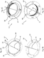
- Fig. 4A is a perspective view of an attachment ring 8 of the ostomy device 2 according to the invention viewed from above, whereas Fig. 4B is a perspective view of the attachment ring 8 shown in Fig. 4A , however, viewed from below.
- the attachment ring 8 comprises a centrally located ring-shaped disc provided with three openings 42, each opening 42 provided with a radially adjacent resilient structure 44.
- the openings 42 comprise a tangentially extending central structure 84 surrounded by corresponding locking elements 86 configured to lockingly engage with the corresponding engagement profiles (cf. 78 in Fig. 2A ) of a connecting member 10 on the upper portion of the attachment ring 8.
- the resilient structure 44 provided for each opening 42 makes it possible to compensate for imperfect fitting of corresponding engagement elements 18 of a connecting member 10 attached to the attachment ring 8.
- the resilient structure 44 comprises a wavy profile adjacent to the opening 42 and further comprises a slot 88 making displacement of the resilient structure 44 possible, whereby engagement of a corresponding engagement element 48 of a connecting element 10 is possible.
- Fig. 4E is a schematic cross-sectional view of a part of an attachment ring 8 of an ostomy device 2 according to the invention placed above a base plate 6, while Fig. 4F is a schematic cross-sectional view of an attachment ring 8 as shown in Fig. 4E attached to the base plate 6.
- the attachment ring 8 comprises a protruding peripherical located planar ring portion 50 configured to be brought into engagement with a fastening recess/cavity 54 provided on the inner portion of a locking flange 52 of a base plate 6.
- Fig. 4C is a perspective view of a closing disc 12 of an ostomy device 2 according to the invention viewed from below
- Fig. 4D is a perspective view of the closing disc 12 shown in Fig. 4C , however, viewed from above.
- the closing disc 12 shown essentially corresponds to the closing disc 12 shown in Fig. 2C and Fig 2D .
- the closing disc 12 shown in Fig. 4C and Fig. 4D is, however, provided with cylindrical peripheral edge/enclosing portion 58 extending along the longitudinal axis X as well as a number of ventilation apertures 56 located on the upper part of the adjacent portion 11 of the closing disc 12, thereby differing from the closing disc 12 shown in Fig. 2C and Fig. 2D .
- the closing disc 12 shown in Fig. 4C and Fig. 4D is configured to receive an annular filter 40, e.g. a carbon filter (cf. Fig. 5A ).
- the carbon filter 40 may suitably be placed peripherally along the inner portion of the peripherical edge 58.
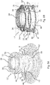
- Fig. 5A is a perspective view of an ostomy device 2 according to the invention, shown in disassembled configuration and viewed from above.
- the ostomy device 2 comprises a connecting element 10 configured to be attached to an attachment ring 8 configured to be detachably attached to a fastening recess (cavity) on the inner portion of the locking flange 52 of the base plate 6 (as shown in Fig. 4E ).
- the attachment ring 8 corresponds to the attachment ring 8 shown in Fig. 4A and Fig. 4B and thus comprises openings 42 and adjacent resilient structures 44 provided at a planar upper portion.
- the connecting element 10 corresponds to the connecting element 10 shown in Fig. 2A and Fig. 2B or Fig. 3C and Fig. 3D .
- the connecting element 10 comprises openings 38 for receiving the engaging elements (18 see Fig. 5B ) of the above placed closing disc 12.
- the connecting element 10 further comprises upwards protruding protrusions 22.
- annular carbon filter 40 Above the connecting element 10, an annular carbon filter 40 is provided.
- the carbon filter 40 is configured to be enclosed by a closing disc 12 placed above the carbon filter 40.
- a suited closing disc 12 is shown in Fig. 4C and Fig. 4D .
- the closing disc 12 comprises an adjacent portion 11 having ventilation apertures 56 located along the peripheral portion of the adjacent portion 11.
- the closing disc 12 further comprises a flange 14 having an internal threaded area 30.
- the flange 40 is upwards protruding and extend perpendicular to the adjacent portion 11 of the closing disc 12.
- Fig. 5B is a perspective view of parts of the ostomy device 2 according to the invention.
- the ostomy device 2 comprises an attachment ring 8 corresponding to the attachment ring 8 shown in Fig. 5A .
- the connecting element 10 comprises a planar upper side provided with openings 38 configured to receive L-shaped engaging elements 48 of a closing disc 12 placed above the planar upper side.
- the connecting element 10 comprises protruding protrusions 22 suited for acting as guiding means, when rotating the connecting element 10 about its longitudinal axis to mount or demount the connecting element 10 from the underlying attachment ring 8.
- the connecting element 10 further comprises T-shaped engaging elements 18 configured to be brought into engagement with corresponding openings 42 of the attachment ring 8.
- the closing disc 12 corresponds to the closing disc 12 shown in Fig. 2C and Fig. 2D .
- the closing disc 12 comprises a disc-shaped adjacent portion 11 configured to engage with the adjacent, underlying connecting element 10.
- the closing disc 12 is further provided with a, from the adjacent portion 11, upwards protruding cylindric flange 14 extending along the longitudinal axis of the closing disc 12.
- an internal threaded area 30 is provided along the inner side of the flange 14.
- an upwards protruding protrusion 36 is provided on the upper side of the adjacent portion 11.
- the protrusions 36 are configured to function as guiding means in connection with mounting or demounting from an underlying connecting element 10.
- the protruding protrusions 36 comprises an upright profile extending radially and along the longitudinal axis, whereby a finger nail may be brought into engagement with the profile in order to provide a sufficiently effective torque for mounting or demounting from an underlying connecting element 10.
- a slot/notch 74 with a suitable geometry and size is provided.
- the number of protruding protrusions 36 and the number of engaging elements 48 may be varied.
- a closing disc 12 having one, two, three, four five, six or more protruding protrusions 36 and e.g. three engaging elements 48. It may be an advantage that the protrusions 36 as well as the engaging elements 48 are evenly distributed along the adjacent portion 11 of the closing disc 12, whereby the angle between adjacent protrusions 36 and corresponding engaging elements 48 is approximately 120° in the case of three protrusions 36.
- Fig. 6A is a schematic cross-sectional view of an ostomy device 2 according to the invention, viewed from the side.
- the ostomy device 2 comprises an attachment ring 8 having a peripherally placed planar ring portion 50 configured to be brought into engagement with a fastening recess 26 provided on the inner portion of a locking flange of the base plate 6.
- the attachment ring 8 is brought into engagement with an engagement element 38 of the connecting element 10 placed above the attachment ring 8.
- an annular attachment recess 26 is provided at the attachment ring 8.
- the attachment recess 26 is suited and configured for fastening a collecting element corresponding to the collecting element 28 shown in Fig. 1A and Fig. 1B . Thereby, it is possible to fasten the proximal end of e.g. a condom in the fastening recess 26 of the connecting element 10.
- the connecting element 10 is fastened or attached to a shield 60, the shield 60 comprising a curvy surface 70 enabling deformation (compression and extension) of the shield 60.
- a shield 60 comprising a curvy surface 70 enabling deformation (compression and extension) of the shield 60.
- two finger grips 62 for attachment to e.g. a belt (not shown) is provided. This may in particular be suited for more diverent users.
- the finger grips 62 may further be used for handling the shield 60.
- a protruding profile 64 is provided on the topmost port of the shield 60. The profile 64 may be used for rotating the shield 60.
- Fig. 6B is a perspective view of parts of the ostomy device 2 corresponding to the ostomy device 2 shown in Fig. 6A .
- the ostomy device 2 comprises a shield 60 having a curvy surface 70, peripheral finger grips 62 and a centrally placed dome 68 having a protruding profile 64.
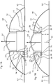
- Fig. 7A is a schematic cross-sectional view of an ostomy device 2 according to the invention, shown in a first configuration
- Fig. 7B is a cross-sectional view of the ostomy device 2 shown in Fig. 7A in another configuration.
- the ostomy device 2 comprises an attachment ring 8 having a peripheral planar ring portion 50 configured to be brought into engagement with an attachment recess 26 of a locking flange 14 of a base plate 6.
- the attachment ring 8 has been brought into engagement with an engagement element 48 of the closing disc 12 placed above the attachment ring 8.
- the closing disc 12 comprises an annularly shaped attachment recess 26 for fastening/attaching a collecting element 28 as shown in Fig. 1A and Fig. 1B .
- a condom in the attachment recess 26 of the closing disc 12.
- the closing disc 12 is attached or fastened to the attachment ring 8 by means of an engagement element 28, brought into locking engagement with an opening ej vist of the attachment ring 8.
- the closing disc 12 is provided with a protrusion 36, provided with a notch (slot) 74. A finger nail may be inserted into the notch 74 for moving the closing disc 12 in the longitudinal axis X.
- the closing disc 12 is provided with an adjacent portion 11 and a cylindrical flange 14, extending perpendicular to the adjacent portion 11 and parallel to the longitudinal axis X.
- the flange 14 is provided with an internal threaded area 30.
- the ostomy device 2 comprises a shield 60 provided with a smooth surface 72, peripheral finger grips 62 and a centrally placed blocking element 16 provided with an outer threaded area 32 configured to be brought into engagement with the inner threaded area 30 of the flange 14.
- the shield 60 comprises a sealing element 92 shaped as an O-ring (preferably made of a resilient material as e.g. an elastomer such as rubber) and configured to seal against the underlying base plate 6.
- the sealing element 92 is compressed, thereby sealing the shield 60 and the ostomy device 2 against water ingress.
- the displacement of the shield 60 against the stoma 20 results in the radial displacement of the finger grips 62 of the shield 60 and the sealing element 92.
- a radial force from the shield 60 against the sealing element 92 and the finger grips 62 of the shield 60 is provided, whereby the shield 60 is tightened and is able to resist pressure from water acting against the shield 60.
- the shield 60 further comprises a protruding profile 62 extending from the top of the shield 60, whereby it is possible to rotate the shield 60 relative to the longitudinal axis of the ostomy device 2.
- Fig. 7A shows the attachment ring 8 and the thereto attached closing disc 12 in the lowermost position (farthest from the top of the shield 12).
- Fig. 7B shows the attachment ring 8 and the thereto attached closing disc 12 in the topmost position (closest to the top of the shield 60). In this configuration, the distance H from the underside of the attachment ring 8 and the bottom part of the shield 60 is indicated.
- the ostomy device 2 shown in Fig. 7A and Fig. 7B is configured to adjust the placement of the attachment ring 8 and the thereto attached closing disc 12 relative to the top of the shield 60.
- a collecting element 28 e.g. a condom placed in the cavity of the blocking element 16.
- Fig. 8A is a schematic cross-sectional view of an ostomy device 2 according to the invention.
- the ostomy device 2 comprises a shield 60 having a dome-shaped surface 72 and a finger grip 62 located at the periphery.
- a planar top portion 66 is provided, the planar top portion 66 being provided with a protruding profile 64.
- the shield 60 comprises a centrally placed blocking element 16 provided with an external threaded area 32 configured to engage with an internal threaded area 30 provided at a closing disc 12 being attached to a connecting element 10 attached to an underlying attachment ring 8.
- the attachment ring 8 comprises a planar ring portion 50 configured to engage with the inner portion of an attachment recess 26 provided at the locking flange of the base plate 6.
- the attachment ring 8 is shown to be engage with an engagement element 46 of the connecting element 10 placed above the connecting element 10.
- An attachment recess 26 is provided at the connecting element 10 for attachment of a collecting element 28 e.g. as shown in Fig. 1A and Fig. 1B .
- a collecting element 28 e.g. as shown in Fig. 1A and Fig. 1B .
- Using an attachment recess 26 makes it possible to attach, to the attachment recess 26, the proximal folded end of e.g. a condom.
- the connecting element 10 is provided with an inner rounded edge 90 for avoiding damage (e.g. by puncturing) to the collecting element 28 when in contact with the connecting element 10.
- the closing disc 12 By rotation of the shield 60 relative to the closing disc 12, the closing disc 12 is displaced along the longitudinal axis X of the ostomy device 2.
- the pressure by which the underside of the blocking element 16 is forced against the free end of the stoma and the pouch or condom enclosing the free end of the stoma By rotation of the shield 60, it is thus possible to vary the extend of blocking of the stoma.
- the ostomy device 2 makes it possible to avoid the use of a traditional stoma pouch. Furthermore, the wearer may perform daily and ordinary activities such as swimming and further use closely fitting clothes without the ostomy device 2 being visible.
- Fig. 8B is a perspective view of an ostomy device 2 according to the invention.
- the ostomy device 2 comprises a shield 60 having a dome-shaped surface 72 at the periphery of which two finger grips 62 are provided. At the central portion of the top of the shield 60, a smaller dome 68 is provided, from which a three-parted protruding profile 64 is extending.
Description
- The present invention relates to an ostomy device for use in connection with a stoma. More specifically, the invention relates to a device which is suitable for use with a base plate in such a manner, whereby the stoma can be pinched off or blocked for an extended period of time. Subsequently, discharge from the stoma can be collected and emptied without inducing a risk of leakage. Thereby, the risk for skin irritation due to skin contact with faeces or urine is markedly lowered.
US 8,092,437 B2 is regarded as the closest prior art. - In connection with certain diseases such as carcinomas of the colon or rectum, the surgical removal of the bowel (colostomy) or small intestine (ileostomy) or parts thereof is often necessary. After surgery, an artificial opening is created on the body allowing faeces or urine, either from the intestine or the urinary tract, to pass through this opening. The discharge from the ileostomy or colostomy is collected in a stoma pouch or bag.
- Ostomy can be performed in different ways. The most common ostomies include colostomy, ileostomy and urostomy, respectively. In a colostomy operation, part of the colon is brought to the surface of the abdomen to form the stoma. There are two types of colostomy, namely end colostomy and loop colostomy. End colostomy is typically performed if parts of the colon and rectum have been removed. Loop colostomy is typically performed as a temporary measure in acute situations, and by this operation, part of the colon is lifted above skin level and held in place with a stoma rod. In an ileostomy operation, a part of the small intestine (the ileum) is brought to the surface of the abdomen to form the stoma. An ileostomy is typically created in cases where the end part of the small intestine is diseased and may be performed as either an end ileostomy or a loop ileostomy. End ileostomy is made in cases where part of the colon is removed (or need to rest), and the end of the small intestine is brought to the surface of the abdomen to form the stoma. In a loop ileostomy, a loop of the small intestine is lifted above skin level and held in place with a stoma rod. A loop ileostomy may be temporary and performed to protect a surgical join in the bowel. By urostomy, an isolated part of the intestine is brought onto the surface of the abdomen and the other end is sewn up, and the ureters are detached from the bladder and reattached to the isolated section of the intestine. Because this section of the intestine is too small to function as a reservoir, and there is no muscle or valve to control urination, a urostomy pouch to collect the urine is needed.
- It is known in the art to apply base plates (so-called skin plates) in connection with stomas. The base plates are usually fastened or adhered to the skin around the stoma by use of an adhesive. The plates have an orifice/opening (or it may be possible to provide and orifice/opening) through which the stoma can be transferred. Several types of pouches to fit and to be fastened to the base plates are known in the art.
- E.g. from
EP 1 795 157 A2 an ostomy appliance for fastening to a base plate is known. The ostomy appliance comprises an attachment ring, the flange of which is permanently attached to the base plate. The ostomy device further comprises means which are suited for detachably attached to the attachment ring, and a cap having a sealing for the stoma, thereby blocking the stoma. In spite of the sealing cap there is still a risk of leakage from the stoma, if not combined with the use of a stoma pouch. - A number of disadvantages are involved with the use of stoma pouches, including the wearer's reduced mobility and possibility of participating in certain activities (e.g. swimming and bathing as well as other activities where clothing closely fitting the body is required). The wearer may understandably prefer the stoma pouch is not visible beneath the clothing.
- Therefore, an alternative to the known stoma pouches is desired.
- From
WO 2011/031822 A1 , an ostomy appliance is known. The appliance comprises a stoma seal that is self-urging with a dynamic damping resisting changes of seal volume to conform with the stoma shape, a press-fit coupling member and a single-use frangible portion. The appliance further comprises a protecting shield having a seal displacer, a coupling member and a bracing porting, the latter for bracing the single-use frangible portion. The appliance needs not to be used with a pouch, however, the user may need to discharge the stoma frequently due to the limited seal volume. - Furthermore, it is desired to provide a ostomy device which eliminates the wearer's need to discharge the stoma pouch for an extended period of time (e.g. for as long as six hours), while at the same time make possible the release of gas from the stoma.
- It is an object of the present invention to provide an ostomy device that minimises or even eliminates the above disadvantages.
- It is also an object of the present invention to provide an ostomy device that enhances the wearer's mobility, and further makes it possible to participate in various activities without revealing the stoma pouch (e.g. swimming and other activities involving closely fitting clothes).
- It is further an object of the present invention to provide an ostomy device which enables pinching off or blocking the stoma for an extended period of time (e.g. for as long as six hours), while at the same time enables release of gas from the stoma.
- The object of the present invention is achieved by the ostomy device as defined in claim 1. Preferred embodiments are comprised by the dependent claims and further described herein as well as illustrated in the accompanying drawings.
- The ostomy device according to the invention is an ostomy device for attachment to (coupling to) a base plate, wherein the ostomy device comprises an attachment ring configured to detachable attachment to the base plate, wherein the ostomy device further comprises elements with means for detachable attachment to the attachment ring, wherein the ostomy device comprises a shield comprising a blocking element, whereby the stoma may be pinched off/blocked, wherein the blocking element is formed and configured to engage with a collecting element and a herein placed distal part of the stoma.
- Thereby, the stoma may be pinched off, thus, enabling the wearer's use of the ostomy device for periods of e.g. 2-6 hours without the need for the simultaneous use of a stoma pouch. The blocking element is configured to engage with a collecting element and thereby provide a pressure against the stoma which is thereby pinched off/blocked.
- The ostomy device according to the invention may be detachably attached to the base plate through an attachment ring. The ostomy device further comprises elements having means configured for detachable attachment to the attachment ring. These elements may have any suitable shape and geometry.
- The shield may have any suitable shape and geometry. However, it may be an advantage that the shield comprises a spherical part (e.g. formed as the surface of a globular structure/dome or an oval structure). The blocking element may suitably have a geometry providing a predefined pressure distribution against the distal part of the stoma, when the blocking element is brought into engagement with a collecting element and the herein placed distal part of the stoma, thereby resulting in the blocking or pinching off of the stoma.
- In may be advantageous that the blocking element is displaceably attached to the base plate.
- Thereby, the level of blocking or pinching off can be adapted by displacing the blocking element relative to the base plate, since the force and, thus, the pressure by the blocking element acting on the free end of the stoma are defined e.g. by the distance between the blocking element and the base plate. Thus, it is possible to provide a shield having a distance-adjustable blocking element enabling selective adjustment of the blocking of the stoma.
- It may be an advantage that the shield is symmetrical, and that the blocking element is centrally placed.
- The shield has preferably a convex outer side and a concave part, the latter configured to be placed against the base plate.
- It may be an advantage that the ostomy device comprises a closing disc provided with a threaded area, and further that the blocking element is provided with a corresponding threaded area configured to engage with the threaded area of the closing disc. Thereby, the blocking element may be displaced upwards and downwards so as to vary the pressure by the blocking element on the distal end of the stoma in a simple and continuous manner.
- It may be an advantage that the closing disc is provided with an internal threaded area extending along an internal cylinder-shaped surface and that the ostomy device comprises a blocking element comprising a cylindrical portion provided with an outer (externally provided) threaded area extending along the outer cylindrical surface of the cylindrical portion.
- It may be an advantage that the blocking element is centrally placed on the inner portion of the shield. Thereby, it is possible to provide a shield having a blocking element that can easily be provided with an outer (external) threaded area configured to attachment to a structure (e.g. a closing disc) having a corresponding inner threaded area.
- It may be an advantage that the shield covers an area extending along the area of the base plate to which the ostomy device is attached.
- Thereby, the shield protects the base plate and ensures that the shield sufficiently covers the area needed.
- A cavity is present in the central part of the blocking element, wherein the cavity is configured to receive the distal part of a stoma. Thereby, the height of the blocking element (and, thus, the size of the shield) may be reduced, since the blocking element may thus receive the part of the stoma to be blocked or pinched off. Thereby, it is possible to place, in the cavity, the stoma as well the free end of the stoma in the collecting element (e.g. a pouch or a condom).
- It may be an advantage that the ostomy device comprises a connection member detachably attached to the attachment ring. The application of a detachably mounted/attached connecting element makes it possible to attach and detach the connecting element e.g. when changing collecting elements (e.g. a pouch or a condom). The collecting element may e.g. be attached in a fastening recess provided in the connecting element.
- The ostomy device comprises a closing disc suited for attachment to the attachment ring or the connecting element. Thereby, it is possible to attach the shield to the closing disc and ensure mechanical attachment to the base plate. It may be preferred that the closing disc is provided with attachment elements for detachable attachment of the shield to the closing disc. It may be an advantage that these attachment elements are configured to enable adjustment of the distance between the closing disc and the base plate.
- It may be an advantage that the closing disc comprises a flange having an internal threaded area and comprises an adjacent portion, wherein the flange extends perpendicular to the adjacent portion. Thereby, the stoma can be lead through the opening in the flange, and a flexible collecting element e.g. formed as a pouch (alternatively a condom) may suitably be attached to a ring-shaped attachment recess provided in a connecting element. The collecting element thereby encloses the distal end of the stoma and enables collection of the discharge from the stoma.
- It may be an advantage that the shield is provided with one or more grips, e.g. fitting the fingers of the hand. Thereby, the handling of the shield is eased. In a preferred embodiment of the invention, the shield comprises two such finger grips opposed to each other at the periphery of the shield.
- It may be an advantage that the lower portion of the closing disc is provided with a number of engagement elements configured to be brought into locking engagement with corresponding openings of an underlying connecting element or an underlying attachment ring. Thereby, it is possible to provide an easy attachment of the closing disc to the underlying connecting element or the underlying attachment ring.
- It may be an advantage that the engagement elements are L-shaped. In one embodiment of the invention, the engagement elements are rotatably attached to the closing disc.
- In a preferred embodiment of the invention, the L-shaped engagement elements comprise a central portion extending along the longitudinal axis of the closing disc and comprise an engagement structure extending perpendicular to the longitudinal axis of the closing disc.
- The closing disc may suitably comprise one, two, three, four, five, six or more engagement elements. In some embodiments of the invention, the engagement elements may be evenly distributed along the lower portion of the adjacent portion of the closing disc. If e.g. three engagement elements are present, the distance between adjacent engagement elements is approximately 120°.
- It may be an advantage that the connecting element or the closing disc or both is provided with a number of T-shaped engagement elements configured to be brought in to engagement with corresponding openings of an adjacent attachment ring or an adjacent connecting element. Thereby, it is possible to provide an effective and easy attachment of the closing disc to the attachment ring or the connecting element.
- It may be an advantage that the T-shaped engagement elements comprise a central portion extending along the longitudinal axis of the connecting element and comprise two engagement structures extending perpendicular to the longitudinal axis of connecting element. This type of engagement elements makes it possible to rotate the closing disc and, thus, place the closing disc in a number of configurations, whereby the closing disc becomes locked or unlocked relative to the attachment ring or the connecting element.
- It may be an advantage that the engagement elements are evenly distributed along the ring-shaped structure of the connecting element.
- It may be an advantage that the lower portion of the closing disc is provided with a number of recesses configured to receive protrusions provided on the connecting element.
- The number of recesses should preferably at least equal the number of protruding protrusions on the connecting element. The number of recesses may, however, equal the number of protruding protrusions on the connecting elements. Suitably, the number of recesses on the closing disc may be one, two, three, four, five, six or more, depending on the number of protruding protrusions on the connecting element.
- The recesses should be provided and distributed such as to angularly correspond to the protruding protrusions on the connecting element, thus, enabling engagement of the protruding protrusions with the recesses.
- In one embodiment of the invention, the central portion is rotatably attached to the connecting element, whereby the recesses enable rotation of the engagement elements about the longitudinal axis of the central portion. Thereby, a safe and secure locking is provided by applying simple mechanical means.
- It may be an advantage that the attachment ring is provided with openings, each opening being provided with a radial adjacent resilient structure.
- The use of a resilient structure for each opening ensures that variations in the different portions are acceptable, while providing easy attachment of the engagement elements to the attachment ring. Furthermore, the resilient structures ensure locking engagement between the openings and the engagement elements.
- In one embodiment of the invention, the resilient structure is a wavy/corrugated profile next to the opening and further next to a slit, thus, enabling displacement of the resilient structure, whereby the receipt of a corresponding engagement element of a connecting element is achieved.
- In a preferred embodiment, the attachment ring is provided with a centrally placed disc having three openings, each opening provided with a radial adjacent resilient structure.
- The openings may advantageously comprise a tangentially extending center structure surrounded by adjacent locking elements configured to provide locking engagement with a connecting element of corresponding engagement elements at the upper portion of the attachment ring.
- It may be an advantage that the closing disc comprises an attachment recess configured for receipt and attachment of a collecting element. Thereby, it is possible to attach a collecting element surrounding the distal portion of the stoma, whereby discharge from the stoma may be collected.
- It may be an advantage that the attachment recess is annular and has a circular cross-section.
- It may be an advantage that the closing disc comprises a peripheral edge extending from the adjacent portion of the closing disc along the longitudinal axis. Thereby, an area is provided enabling the use of an annularly shaped filter.
- It may be an advantage that the ostomy device comprises an integrated or built-in filter. Thereby, it is possible to clean/reduce the odour of the gas escaping from the stoma. It may be advantageous to use a carbon filter as this type of filter effectively cleans the gas, thereby markedly reducing the odours from the ostomy device.
- It may be an advantage that the connecting element comprises a sealing portion extending along the longitudinal axis of the ostomy device. The sealing portion further ensures retention of discharge gathered by the collecting element attached to the connecting element attached to the attachment recess of the connecting element, which is practical in connection with the removal of the collecting element from the connecting element.
- It may be an advantageous to provide one or more engagement profiles for engaging with the shield. The engagement provides may comprise a protruding profile configured to enable rotation of the shield using the engagement profiles.
- The invention is further explained in relation to the accompanying drawings, where
- Fig. 1A
- is a schematically cross-sectional view of a ostomy device according to the invention before the blocking element is attached,
- Fig. 1B
- is a cross-sectional view of the ostomy device shown in
Fig. 1A in a configuration, where the blocking element is attached, whereby the stoma is pinched off, - Fig. 2A
- is a perspective view of a connecting element according to the invention viewed from below,
- Fig. 2B
- is a perspective view of the connecting element shown I
Fig. 2A viewed from above, - Fig. 2C
- is a perspective view of a closing disc according to the invention viewed from above,
- Fig. 2D
- is a perspective view of the closing disc shown in
Fig. 2C viewed from below, - Fig. 3A
- is a perspective view of a closing disc according to the invention viewed from below,
- Fig. 3B
- is a perspective view of the closing disc shown in
Fig. 3A viewed from above, - Fig. 3C
- is a perspective view of a connecting element according to the invention view from below,
- Fig. 3D
- is a perspective view of the connecting element shown in
Fig. 3C viewed from above, - Fig. 4A
- is a perspective view of an attachment ring according to the invention viewed from above,
- Fig. 4B
- is a perspective view of the attachment ring shown in
Fig. 4A viewed from below, - Fig. 4C
- is a perspective view of a closing disc according to the invention viewed from below,
- Fig. 4D
- is a perspective view of the closing disc shown in
Fig. 4C viewed from above, - Fig. 4E
- is a schematically cross-sectional view of a portion of an attachment ring according to the invention placed on a base plate,
- Fig. 4F
- is a schematically cross-sectional view of the attachment ring shown in
Fig. 4E attached to the base plate, - Fig. 5A
- is a perspective view of an ostomy device according to the invention in a exploded configuration, viewed from above,
- Fig. 5B
- is a perspective view of portions of an ostomy device according to the invention,
- Fig. 6A
- is a schematically cross-sectional view of an ostomy device according to the invention view from the side,
- Fig. 6B
- is a perspective view of portions of an ostomy device according to the invention,
- Fig. 7A
- is a schematically cross-sectional view of an ostomy device according to the invention in a first configuration,
- Fig. 7B
- is a schematically cross-sectional view of the ostomy device shown in
Fig. 7A in another configuration, - Fig. 8A
- is a schematically view of an ostomy device according to the invention, and
- Fig. 8B
- shows a perspective view of an ostomy device according to the invention.
- The accompanying drawings are only intended for illustrating non-limiting embodiments. A number of other embodiments are possible within the scope of the present invention and will readily be recognised by the person skilled in the art. In the following, similar or identical elements of the various embodiments have identical reference numbers.
-
Fig. 1A illustrates a schematically cross-sectional view of anostomy device 2 according to the invention before the blockingelement 16 shown inFig. 1B is attached.Fig. 1B illustrates a cross-sectional view of theostomy device 2 shown inFig. 1A in a configuration, where the blockingelement 16 is attached, whereby thestoma 20 is pinched off/blocked to hinder leak of the discharge from thestoma 20. - The
ostomy device 2 is attached to abase plate 6, which is fastened to the wearer'sskin 4. Theostomy device 2 comprises anattachment ring 8 configured to detachable attachment on the inner portion of a lockingflange 52 of thebase plate 6, provided in an attachment recess (cf.Fig. 4E ). Theostomy device 2 further comprises an annularly-shaped connectingelement 10 attached to theattachment ring 8 through theengagement elements 18, saidengagement elements 18 configured to be engaged with corresponding openings/apertures 42 of the attachment ring 8 (cf.Fig. 4A and Fig. 4B for further details). The annularly shaped connectingelement 10 is provided withprotrusions 22 configured to be received by a corresponding aperture (or recess) in theadjacent portion 11 of the closing disc 12 (cf.Fig. 2A and Fig. 2B ). - The
closing disc 12 comprises aflange 14 having an internal threadedarea 30. The flange 13 extends vertically along theadjacent portion 11 of theclosing disc 12. Thestoma 20 is led through theopening 34 of theostomy device 2. Aflexible collecting element 28 formed as a pouch (alternatively a condom) is attached to anattachment recess 26 provided in the annularly shaped connectingelement 10. The collectingelement 28 surrounds the distal portion of thestoma 20 and may thus collect the discharge (faeces) excreted from thestoma 20. Theostomy device 2 according to the invention can thereby be applied without a pouch attached to theattachment flange 52. Accordingly, the invention makes it possible to use a "pouch-free ostomy device". - While the
stoma 20 shown inFig. 1A is just surrounded by the surrounding flexible collectingelement 28, thestoma 20 is pinched-off as shown inFig. 1B . InFig. 1B , ashield 60 is attached to theclosing disc 12, theshield 60 comprising a dome-shaped shell (dome) having a centrally placed blockingelement 16. - The blocking
element 16 pinches against the collectingelement 28 and thestoma 20 surrounded by the blockingelement 16. Thereby, thestoma 20 is blocked, enabling the wearer of theostomy device 2 to use theostomy device 2 for period of e.g. 2-8 hours without a collectingelement 28. AlthoughFig. 1B seems to show a slit between the back portion of the blockingelement 16 and thestoma 20, the back side of the blockingelement 16 rests against the collectingelement 28 and thereby make a pressure against thestoma 20, which is thus pinched off. - The blocking
element 16 comprises an external threadedarea 32 fitting the corresponding internal threadedarea 30 of theclosing disc 12. The blockingelement 16 and thus theshield 60 are rotatably attached to theclosing disc 12. The blockingelement 16 and theshield 60 may by rotation of theshield 60 be moved closer to or further away from thebase plate 6. At the topmost part of theshield 60, a protrudingprofile 64 is provided. This protrudingprofile 64 functions as a grip which may be used by the wearer of theostomy device 2 to rotate theshield 60 relative to thebase plate 6. Thus, it is possible to vary the distance between the back side of the blockingelement 16 and thebase plate 6. By rotation of theshield 60, it is thereby possible to vary the force at which the back side of the blockingelement 16 acts against the collectingelement 28 and thestoma 20, whereby a sufficiently pinching off of thestoma 20 is achieved. - As long as the
ostomy device 2 blocks thestoma 20, discharge from thestoma 20 is not excreted. Once theostomy device 2 is unmounted, the collectingelement 28 will fill with discharge from thestoma 20. Subsequently, the collecting element may be unmounted and discarded. Anunused collecting element 28 may thereafter be attached, and theostomy device 2 is ready for further use. Theshield 60 comprises et laterally positionedgrip 62 for mounting to e.g. a belt (not shown), this being specifically suited for more corpulent wearers. Thegrips 62 may equally be used for handling of theshield 60. Theshield 60 may also be equipped with a sealingelement 92 configured to seal theadjacent base plate 6. The sealingelement 92 is formed as an O-ring having an annular cross-section. The sealingelement 92 may preferably be made from a resilient material, like e.g. a rubber material. The compressive force FT (tangentially oriented relative to the shield 60), forcing the peripheral portion of theshield 60 against theadjacent base plate 6, compresses the sealingelement 92, thereby making theshield 60 as well as the ostomy device waterproof/resistant to water ingress. When theshield 60 is mounted on thestoma 20, thegrips 62 of theshield 60 and the thus the sealingelement 82 are displaced radially (to the side), whereby a radially oriented force FR from theshield 60 acts against the sealingelement 92 and thegrips 62. Theshield 60, thus, becomes pre-tightened and thereby able to resist a pressure from water splashing against theshield 60. Accordingly, theshield 60 ensures the underlying or adjacent structures are not brought into contact with the water, whereby theostomy device 2 is suited for bathing and swimming. - The
shield 60 ensures that the wearer of theostomy device 2 may use theostomy device 2 in connection with bathing, swimming or other activities, where toileting is not an option. -
Fig. 2A illustrates, in perspective, a connectingelement 10 of theostomy device 2 viewed from below, whereasFig. 2B illustrates, in perspective, the connectingelement 10 shown inFig. 2A viewed from above. The connectingelement 10 is formed as an annularly shaped structure having a centrally positioned opening. The connectingelement 10 is equipped with threeopenings 38 configured to receive engagement elements 18 (cf.Fig. 2C and Fig. 2D ) from anattachment ring 8 positioned below the connectingelement 10. The threeopenings 38 are evenly distributed along the annularly shaped profile of the connectingelement 10. Thus, the angle betweenadjacent openings 38 is approximately 120°. Theopenings 38 are configured to receive and fixate L-shapedengagement elements 18 of aclosing disc 12 positioned above the connectingelement 10. The number ofopenings 38 may be varied. Thus, a connectingelement 10 having one, two, three four, five, six ormore openings 38 may be provided. Theopenings 38 may suitably be evenly distributed. - The connecting
element 10 further comprises three T-shapedengagement elements 18 configured to be brought into engagement with corresponding openings of an adjacent orunderlying attachment ring 8 suited for receiving such engagement elements 18 (cf.Fig. 4A and Fig. 4B ). The threeengagement elements 18 are evenly distributed along the annularly shaped profile of the connectingelement 10. Thus, angle between adjacent connectingelements 10 is approximately 120°. The T-shapedengagement elements 18 comprises acentral portion 80 extending along the longitudinal axis X of the connectingelements 10 and twoengagement profiles 78 extending perpendicular along the longitudinal axis X of the connectingelement 10. It can be seen that the connectingelement 10 comprises an annularly shapedattachment profile 26 provided at the under-most side of the connectingelement 10. Theattachment profile 26 is configured for attachment of a collectingelement 28 as shown inFig. 1A and Fig. 1B . Thus, it is possible to attach the proximal folded end of e.g. a condom to theattachment recess 26 of the connectingelement 10. - On the upper side of the
connection element 10, upwards protrudingprotrusions 22 are provided. Theseprotrusions 22 are configured to function as guiding means, when the connectingelement 10 is rotated about the longitudinal axis X in connection with the mounting on or demounting from anunderlying attachment ring 8. Theprotrusions 22 may preferably comprise an upright profile extending radially and along the longitudinal axis X. Thereby, it is possible to bring a finger nail into engagement with the profile and thereby provide the required torque in order to mount or demount the connectingelement 10 on or from theattachment ring 8. Theprotrusions 22 may have another shape than the shape shown inFig. 2B . The number ofprotrusions 22 may suitably be varied. Thus, it is possible to provide a connecting element having one, two, three, four, five, six ormore protrusions 22. Theprotrusions 22 may suitably be evenly distributed. In one embodiment of the invention, thecentral portion 80 is rotatably attached to the connectingelement 10, whereby theengagement elements 18 may rotated about the longitudinal axis of thecentral portion 80 using theprotrusions 22. Thus, it is possible to provide a very secure locking using very simple mechanical means. -
Fig. 2C illustrates, in perspective, aclosing disc 12 of theostomy device 2 according to the invention viewed from above, whereasFig. 2D illustrates, in perspective, theclosing disc 12 shown inFig. 2C viewed from below. Theclosing disc 12 comprises a disc-formedadjacent portion 11 configured to be brought into engagement with the underlying or adjacent connectingelement 10 corresponding to the connecting element shown IFig. 2A and Fig. 2B . Theclosing disc 12 further comprises a protrudingflange 14 from the connectingportion 11. Theflange 14 is cylindrical and extends along the longitudinal axis X of theclosing disc 12. An internal threadedarea 30 is provided along the inner side of theflange 14. - On the upper portion of the
adjacent portion 11, upwards protrudingprotrusions 36 is provided, saidprotrusions 36 being configured to function as a guiding means in connection with mounting or demounting from an underlying connectingelement 10. The upwards protrudingprotrusions 36 comprises an upright profile extending radially and along the longitudinal axis X allowing a finger nail to engage with the profile, thereby providing a sufficiently effective torque to mount or demount theadjacent portion 11 from the underlying connectingelement 10. - A slot is provided between the upper part of the
adjacent portion 11 and the lower part of the distal portion of the protrudingprotrusions 36. Thereby, it is possible to place the outer of a finger nail in the slot so as to drag/move theclosing disc 12 in the direction of the longitudinal axis. This feature is convenient when removing, demounting or changing theclosing disc 12. The number of protrudingprotrusions 26 may be varied. Thus, it is possible to provide aclosing disc 12 having one, two, three, four, five, six or more protrudingprotrusions 36. It may be an advantage that the protrudingprotrusions 36 are evenly distributed along theadjacent portion 11 ofclosing disc 12. In the case of three protrudingprotrusions 36, the angle betweenadjacent protrusions 36 is thus approximately 120°. - On the lower portion of the
closing disc 12, three L-shapedengagement elements 48 may be provided. The L-shapedengaging elements 48 are configured to be brought into locking engagement withcorresponding openings 38 of an underlying connecting element 10 (cf.Fig. 2A and Fig. 2B ). The L-shapedengaging elements 48 comprises acentral portion 80 extending along the longitudinal axis X of theclosing disc 12 and further an engagement profile extending perpendicular to the longitudinal axis of theclosing disc 12. More orfewer engagement elements 48 may suitably be provided. Thus, it is possible to provide aclosing disc 12 having one, two, three, four, five, six ormore engagement elements 48. It may be an advantage that theengaging elements 48 are evenly distributed along the lower portion of theadjacent portion 11 of theclosing disc 12. If threeengagement elements 48 are present, the angle betweenadjacent engagement element 48 is thus approximately 120°. - Furthermore, on the lower portion of the
closing disc 12, threerecesses 46 may be provided. Therecesses 46 are configured to receive the protrudingprotrusions 22 shown on the connectingelement 10 and illustrated inFig. 2B . - The number of
recesses 46 should at least equal the number of protrudingprotrusions 22 of the connectingelement 10. The number ofrecesses 46 may suitably equal the number of protrudingprotrusions 22 of the connectingelement 10. It is possible to provide aclosing disc 12 having one, two, three, four, five, six ormore recesses 46 depending on the number of protrudingprotrusions 22 on the connectingelement 22. It is, however, a requirement that therecesses 46 are placed/distributed angularly so as to fit the protrudingprotrusions 22 of the connectingelement 10 to enable engagement with the protrudingprotrusions 22. InFig. 2D , therecesses 46 are evenly distributed along the lower portion of theadjacent portion 11 of theclosing disc 12. Thus, in the case of threeprotrusions 22, the angle betweenadjacent recesses 46 is approximately 120°. -
Fig. 3A is a perspective view of aclosing disc 12 of anostomy device 2 according to the invention viewed from below.Fig. 3B is a perspective view from above of theclosing disc 12 shown inFig. 3A . Theclosing disc 12 is provided with a disc-shapedadjacent portion 11 configured to be brought into engagement with an adjacent, underlying connectingelement 10. An underlying connectingelement 10 is shown inFig. 2A and Fig. 2B . Theclosing disc 12 further comprises a, from theadjacent portion 11, upwards protrudingcylindrical flange 14 extending along the longitudinal axis X of theclosing disc 12. The inner portion of theflange 14 is provided with an internal threadedarea 30. Theclosing disc 12 essentially corresponds to theclosing disc 12 shown inFig. 2C and Fig. 2D with the exception of therecesses 46 which are shown inFig. 2D . -
Fig. 3C is a perspective view of a connectingelement 10 of anostomy device 2 according to the invention viewed from below, andFig. 3D is a perspective view of the connectingelement 10 shown inFig. 3C viewed from above. The connectingelement 10 corresponds essentially to the connectingelement 10 shown inFig. 2A and Fig. 2B . The connectingelement 10 shown inFig. 3C and Fig 3C comprises, however, a sealingedge 76 extending along the longitudinal axis X. The sealingedge 76 contributes to retaining discharge collected in the collectingelement 28 attached to theattachment recess 26, when removing the collectingelement 28 from the connectingelement 10. - The one of the three
engagement members 18 is provided with a guiding means 82 extending along the longitudinal axis. The guiding means 82 may be suitable for securing a predefined positioning of the connectingelement 10 relative to anunderlying attachment ring 8 provided with corresponding profile configured to receiving the guiding means 82. The T-shapedengagement members 18 make it possible to provide a double locking system, in which the connectingelement 10 may be clicked off engagement with anunderlying attachment ring 8 by one simple rotation (one click) and may be brought into locking engagement by an additional rotation (a double-click). The corresponding opening provided in theattachment ring 8 may suitably have a geometry facilitating the click and double-click system. -
Fig. 4A is a perspective view of anattachment ring 8 of theostomy device 2 according to the invention viewed from above, whereasFig. 4B is a perspective view of theattachment ring 8 shown inFig. 4A , however, viewed from below. - The
attachment ring 8 comprises a centrally located ring-shaped disc provided with threeopenings 42, each opening 42 provided with a radially adjacentresilient structure 44. Theopenings 42 comprise a tangentially extendingcentral structure 84 surrounded by corresponding lockingelements 86 configured to lockingly engage with the corresponding engagement profiles (cf. 78 inFig. 2A ) of a connectingmember 10 on the upper portion of theattachment ring 8. Theresilient structure 44 provided for eachopening 42 makes it possible to compensate for imperfect fitting ofcorresponding engagement elements 18 of a connectingmember 10 attached to theattachment ring 8. Theresilient structure 44 comprises a wavy profile adjacent to theopening 42 and further comprises aslot 88 making displacement of theresilient structure 44 possible, whereby engagement of acorresponding engagement element 48 of a connectingelement 10 is possible. -
Fig. 4E is a schematic cross-sectional view of a part of anattachment ring 8 of anostomy device 2 according to the invention placed above abase plate 6, whileFig. 4F is a schematic cross-sectional view of anattachment ring 8 as shown inFig. 4E attached to thebase plate 6. Theattachment ring 8 comprises a protruding peripherical locatedplanar ring portion 50 configured to be brought into engagement with a fastening recess/cavity 54 provided on the inner portion of a lockingflange 52 of abase plate 6. -
Fig. 4C is a perspective view of aclosing disc 12 of anostomy device 2 according to the invention viewed from below, whileFig. 4D is a perspective view of theclosing disc 12 shown inFig. 4C , however, viewed from above. Theclosing disc 12 shown essentially corresponds to theclosing disc 12 shown inFig. 2C and Fig 2D . Theclosing disc 12 shown inFig. 4C and Fig. 4D is, however, provided with cylindrical peripheral edge/enclosingportion 58 extending along the longitudinal axis X as well as a number ofventilation apertures 56 located on the upper part of theadjacent portion 11 of theclosing disc 12, thereby differing from theclosing disc 12 shown inFig. 2C and Fig. 2D . Theclosing disc 12 shown inFig. 4C and Fig. 4D is configured to receive anannular filter 40, e.g. a carbon filter (cf.Fig. 5A ). Thecarbon filter 40 may suitably be placed peripherally along the inner portion of theperipherical edge 58. -
Fig. 5A is a perspective view of anostomy device 2 according to the invention, shown in disassembled configuration and viewed from above. Theostomy device 2 comprises a connectingelement 10 configured to be attached to anattachment ring 8 configured to be detachably attached to a fastening recess (cavity) on the inner portion of the lockingflange 52 of the base plate 6 (as shown inFig. 4E ). Theattachment ring 8 corresponds to theattachment ring 8 shown inFig. 4A and Fig. 4B and thus comprisesopenings 42 and adjacentresilient structures 44 provided at a planar upper portion. - Above the
attachment ring 8, a planar annularly-shaped connectingelement 10 is placed. The connectingelement 10 corresponds to the connectingelement 10 shown inFig. 2A and Fig. 2B orFig. 3C and Fig. 3D . The connectingelement 10 comprisesopenings 38 for receiving the engaging elements (18 seeFig. 5B ) of the above placed closingdisc 12. The connectingelement 10 further comprises upwards protrudingprotrusions 22. - Above the connecting
element 10, anannular carbon filter 40 is provided. Thecarbon filter 40 is configured to be enclosed by aclosing disc 12 placed above thecarbon filter 40. Asuited closing disc 12 is shown inFig. 4C and Fig. 4D . Theclosing disc 12 comprises anadjacent portion 11 havingventilation apertures 56 located along the peripheral portion of theadjacent portion 11. Theclosing disc 12 further comprises aflange 14 having an internal threadedarea 30. Theflange 40 is upwards protruding and extend perpendicular to theadjacent portion 11 of theclosing disc 12. -
Fig. 5B is a perspective view of parts of theostomy device 2 according to the invention. Theostomy device 2 comprises anattachment ring 8 corresponding to theattachment ring 8 shown inFig. 5A . - Above the
attachment ring 8, an annularly shaped connectingelement 10 is placed. The connectingelement 10 comprises a planar upper side provided withopenings 38 configured to receive L-shapedengaging elements 48 of aclosing disc 12 placed above the planar upper side. The connectingelement 10 comprises protrudingprotrusions 22 suited for acting as guiding means, when rotating the connectingelement 10 about its longitudinal axis to mount or demount the connectingelement 10 from theunderlying attachment ring 8. The connectingelement 10 further comprises T-shapedengaging elements 18 configured to be brought into engagement withcorresponding openings 42 of theattachment ring 8. - Above the annularly shaped connecting
element 10, aclosing disc 12 is provided. Theclosing disc 12 corresponds to theclosing disc 12 shown inFig. 2C and Fig. 2D . Theclosing disc 12 comprises a disc-shapedadjacent portion 11 configured to engage with the adjacent, underlying connectingelement 10. Theclosing disc 12 is further provided with a, from theadjacent portion 11, upwards protrudingcylindric flange 14 extending along the longitudinal axis of theclosing disc 12. Along the inner side of theflange 14, an internal threadedarea 30 is provided. - On the upper side of the
adjacent portion 11, an upwards protrudingprotrusion 36 is provided. Theprotrusions 36 are configured to function as guiding means in connection with mounting or demounting from an underlying connectingelement 10. The protrudingprotrusions 36 comprises an upright profile extending radially and along the longitudinal axis, whereby a finger nail may be brought into engagement with the profile in order to provide a sufficiently effective torque for mounting or demounting from an underlying connectingelement 10. Between the upper side of theadjacent portion 11 and the underside of the distal portion of the protrudingprotrusions 36, a slot/notch 74 with a suitable geometry and size is provided. Thereby, it is possible to position the front portion of a finger nail into theslot 74 so as to lead theclosing disc 12 along the longitudinal axis, thereby enabling removal, demounting or changing theclosing disc 12. The number of protrudingprotrusions 36 and the number ofengaging elements 48 may be varied. Thus, it is possible to provide aclosing disc 12 having one, two, three, four five, six or moreprotruding protrusions 36 and e.g. threeengaging elements 48. It may be an advantage that theprotrusions 36 as well as theengaging elements 48 are evenly distributed along theadjacent portion 11 of theclosing disc 12, whereby the angle betweenadjacent protrusions 36 and correspondingengaging elements 48 is approximately 120° in the case of threeprotrusions 36. -
Fig. 6A is a schematic cross-sectional view of anostomy device 2 according to the invention, viewed from the side. Theostomy device 2 comprises anattachment ring 8 having a peripherally placedplanar ring portion 50 configured to be brought into engagement with afastening recess 26 provided on the inner portion of a locking flange of thebase plate 6. Theattachment ring 8 is brought into engagement with anengagement element 38 of the connectingelement 10 placed above theattachment ring 8. At theattachment ring 8, anannular attachment recess 26 is provided. Theattachment recess 26 is suited and configured for fastening a collecting element corresponding to the collectingelement 28 shown inFig. 1A and Fig. 1B . Thereby, it is possible to fasten the proximal end of e.g. a condom in thefastening recess 26 of the connectingelement 10. - The connecting
element 10 is fastened or attached to ashield 60, theshield 60 comprising acurvy surface 70 enabling deformation (compression and extension) of theshield 60. On the peripheral portion of theshield 60, twofinger grips 62 for attachment to e.g. a belt (not shown) is provided. This may in particular be suited for more corpulent users. The finger grips 62 may further be used for handling theshield 60. On the topmost port of theshield 60, a protrudingprofile 64 is provided. Theprofile 64 may be used for rotating theshield 60. -
Fig. 6B is a perspective view of parts of theostomy device 2 corresponding to theostomy device 2 shown inFig. 6A . Theostomy device 2 comprises ashield 60 having acurvy surface 70, peripheral finger grips 62 and a centrally placeddome 68 having a protrudingprofile 64. -
Fig. 7A is a schematic cross-sectional view of anostomy device 2 according to the invention, shown in a first configuration, whileFig. 7B is a cross-sectional view of theostomy device 2 shown inFig. 7A in another configuration. Theostomy device 2 comprises anattachment ring 8 having a peripheralplanar ring portion 50 configured to be brought into engagement with anattachment recess 26 of a lockingflange 14 of abase plate 6. - The
attachment ring 8 has been brought into engagement with anengagement element 48 of theclosing disc 12 placed above theattachment ring 8. Theclosing disc 12 comprises an annularly shapedattachment recess 26 for fastening/attaching a collectingelement 28 as shown inFig. 1A and Fig. 1B . Thus, it is possible to fasten the proximal folded end of e.g. a condom in theattachment recess 26 of theclosing disc 12. - The
closing disc 12 is attached or fastened to theattachment ring 8 by means of anengagement element 28, brought into locking engagement with an opening ej vist of theattachment ring 8. Theclosing disc 12 is provided with aprotrusion 36, provided with a notch (slot) 74. A finger nail may be inserted into thenotch 74 for moving theclosing disc 12 in the longitudinal axis X. Theclosing disc 12 is provided with anadjacent portion 11 and acylindrical flange 14, extending perpendicular to theadjacent portion 11 and parallel to the longitudinal axis X. Theflange 14 is provided with an internal threadedarea 30. - The
ostomy device 2 comprises ashield 60 provided with asmooth surface 72, peripheral finger grips 62 and a centrally placed blockingelement 16 provided with an outer threadedarea 32 configured to be brought into engagement with the inner threadedarea 30 of theflange 14. Theshield 60 comprises a sealingelement 92 shaped as an O-ring (preferably made of a resilient material as e.g. an elastomer such as rubber) and configured to seal against theunderlying base plate 6. Once theattachment ring 8 is fastened/attached to theunderlying base plate 6 and the blockingelement 16 is screwed towards thebase plate 6 along thedirection 94, the peripheral portion of theshield 60 is forced against theunderlying base plate 6 by a compressive force. Thus, the sealingelement 92 is compressed, thereby sealing theshield 60 and theostomy device 2 against water ingress. The displacement of theshield 60 against thestoma 20 results in the radial displacement of the finger grips 62 of theshield 60 and the sealingelement 92. Thereby, a radial force from theshield 60 against the sealingelement 92 and the finger grips 62 of theshield 60 is provided, whereby theshield 60 is tightened and is able to resist pressure from water acting against theshield 60. Theshield 60 further comprises a protrudingprofile 62 extending from the top of theshield 60, whereby it is possible to rotate theshield 60 relative to the longitudinal axis of theostomy device 2. -
Fig. 7A shows theattachment ring 8 and the thereto attachedclosing disc 12 in the lowermost position (farthest from the top of the shield 12).Fig. 7B shows theattachment ring 8 and the thereto attachedclosing disc 12 in the topmost position (closest to the top of the shield 60). In this configuration, the distance H from the underside of theattachment ring 8 and the bottom part of theshield 60 is indicated. - The
ostomy device 2 shown inFig. 7A and Fig. 7B is configured to adjust the placement of theattachment ring 8 and the thereto attachedclosing disc 12 relative to the top of theshield 60. Thus, it is possible to adjust the placement of theattachment ring 8 and the thereto attachedclosing disc 12 in order to pinch off the stoma, the distal end of which is enclosed by a collecting element 28 (e.g. a condom) placed in the cavity of the blockingelement 16. -
Fig. 8A is a schematic cross-sectional view of anostomy device 2 according to the invention. Theostomy device 2 comprises ashield 60 having a dome-shapedsurface 72 and afinger grip 62 located at the periphery. At the topmost portion of theshield 60, a planartop portion 66 is provided, the planartop portion 66 being provided with a protrudingprofile 64. Thus, it is possible to rotate theshield 6 about the longitudinal axis X of theostomy device 2. - The
shield 60 comprises a centrally placed blockingelement 16 provided with an external threadedarea 32 configured to engage with an internal threadedarea 30 provided at aclosing disc 12 being attached to a connectingelement 10 attached to anunderlying attachment ring 8. Theattachment ring 8 comprises aplanar ring portion 50 configured to engage with the inner portion of anattachment recess 26 provided at the locking flange of thebase plate 6. Theattachment ring 8 is shown to be engage with anengagement element 46 of the connectingelement 10 placed above the connectingelement 10. - An
attachment recess 26 is provided at the connectingelement 10 for attachment of a collectingelement 28 e.g. as shown inFig. 1A and Fig. 1B . Using anattachment recess 26 makes it possible to attach, to theattachment recess 26, the proximal folded end of e.g. a condom. - The connecting
element 10 is provided with an inner rounded edge 90 for avoiding damage (e.g. by puncturing) to the collectingelement 28 when in contact with the connectingelement 10. - By rotation of the
shield 60 relative to theclosing disc 12, theclosing disc 12 is displaced along the longitudinal axis X of theostomy device 2. Thus, it is possible to vary the pressure by which the underside of the blockingelement 16 is forced against the free end of the stoma and the pouch or condom enclosing the free end of the stoma. By rotation of theshield 60, it is thus possible to vary the extend of blocking of the stoma. Theostomy device 2 makes it possible to avoid the use of a traditional stoma pouch. Furthermore, the wearer may perform daily and ordinary activities such as swimming and further use closely fitting clothes without theostomy device 2 being visible. -
Fig. 8B is a perspective view of anostomy device 2 according to the invention. Theostomy device 2 comprises ashield 60 having a dome-shapedsurface 72 at the periphery of which twofinger grips 62 are provided. At the central portion of the top of theshield 60, asmaller dome 68 is provided, from which a three-parted protrudingprofile 64 is extending. -
- 2
- Ostomy device
- 4
- Skin
- 6
- Base plate
- 8
- Attachment ring
- 10
- Connecting element
- 11
- Adjacent portion
- 12
- Closing disc
- 14
- Flange
- 16
- Blocking element
- 18
- Engagement element (e.g. L-shaped)
- 20
- Stoma
- 22
- Protrusion
- 24
- Ring porting
- 26
- Attachment recess
- 28
- Collecting element
- 30
- Inner threaded area
- 32
- External threaded area
- 34
- Opening
- 36
- Protrusion
- 38
- Aperture/opening
- 40
- Filter
- 42
- Aperture/opening
- 44
- Resilient structure
- 46
- Recess
- 48
- Engagement element
- 50
- Planar ring portion
- H
- Hight
- 52
- Flange
- 54
- Cavity/recess
- 56
- Ventilation aperture
- 58
- Peripheral edge (enclosing portion)
- 60
- Shield
- 62
- Finger grip
- 64
- Protruding profile
- 66
- Planar top portion
- 68
- Dome
- 70
- Curvy surface
- 72
- Surface
- 74
- Notch (slot)
- 76
- Sealing edge
- 78
- Engagement profile
- 80
- Central portion
- 82
- Guiding means
- 84
- Central structure
- 86
- Locking element
- 88
- Slot
- 90
- Rounded edge
- 92
- Sealing element
- 94
- Direction
- X
- Longitudinal axis
- FT
- Compressive force
- FR
- Radially oriented force
Claims (14)
- Ostomy device (2) for attachment to a base plate (6), wherein the ostomy device (2) comprises an attachment ring (8) configured for detachable attachment to the base plate(6), wherein the ostomy devices further comprises elements (10, 12, 16, 28) having means (18, 48, 78, 80) configured for detachable attachment to the attachment ring (8), and a shield (60) having a blocking element (16) for blocking a stoma (20), characterised in that the blocking element (16) has a cavity in the central part of the blocking element (16), wherein the cavity is configured to receive a distal portion of a stoma (20), and wherein the blocking element (16) is shaped and configured to engage with a collecting element (28), and in that the ostomy device (2) comprises a closing disc (12) having a threaded area (30), and in that the blocking element (16) is provided with a corresponding threaded area (32) configured to be brought into engagement with the threaded area (30) of the closing disc (12).
- Ostomy device (2) according to claim 1, characterised in that the blocking element (16) is displaceably attached to the base plate (6).
- Ostomy device (2) according to claim 1 or 2, characterised in that the closing disc (12) has an internal threaded area (30) along an internal cylinder surface and a cylindrical blocking element (16) having an external threaded area (32) extending along the external cylinder surface.
- Ostomy device (2) according to any one of the preceding claims, characterised in that the blocking element (16) is placed centrally on the inner portion of the shield (60).
- Ostomy device (2) according to any one of the preceding claims, characterised in that the shield (60) covers an area extending beyond an area (52) of the base plate (6) to which base plate (6) the ostomy device (2) is attached.
- Ostomy device (2) according to any one of the preceding claims, characterised in that the ostomy device (2) comprises a connecting element detachhably attached to the attachment ring (8).
- Ostomy device (2) according to any one of the preceding claims, characterised in that the ostomy device (2) comprises a closing disc (12) for attachment to the attachment ring (8) or to the connecting element (10).
- Ostomy device (2) according to claim 7, 8, characterised in that the closing disc (12) comprises a flange (14) having an internal threaded area (30) and an adjacent part (11), where the flange (14) extends perpendicular to the adjacent part (11).
- Ostomy device (2) according to any one of the preceding claims, characterised in that a number of engagement elements (48) is provided at the underside of the closing disc (12), said engagement elements (48) being configured to be in locking engagement with corresponding openings (38, 42) of the underlying connecting element (10) or the underlying attachment ring (8).
- Ostomy device (2) according to any one of the preceding claims, characterised in that the connecting element (10) or the closing disc (12) is provided with a number of T-shaped engagement elements (18) configured to be brought into engagement with corresponding openings (38, 42) of the underlying attachment ring (8) or the underlying connecting element (10).
- Ostomy device (2) according to any one of the preceding claims, characterised in that the attachment ring (8) is provided with openings (42) each provided with a radial adjacent resilient structure (44).
- Ostomy device (2) according to any one of the preceding claims, characterised in that the closing disc (12) comprises an attachment recess (26) configured for receiving and attaching a collecting element (28).
- Ostomy device (2) according to any one of the preceding claims, characterised in that the closing disc (12) comprises a peripheral edge (76) extending from the adjacent part (11) of the closing disc (12) along the longitudinal axis of the closing disc (12).
- Ostomy device (2) according to any one of claims 6-13, characterised in that the connecting element (10) comprise a sealing edge (76) extending along the longitudinal axis (X) of the ostomy device (2).
Applications Claiming Priority (1)
| Application Number | Priority Date | Filing Date | Title |
|---|---|---|---|
| DKPA201700325A DK179423B1 (en) | 2017-05-31 | 2017-05-31 | An ostomy appliance |
Publications (2)
| Publication Number | Publication Date |
|---|---|
| EP3409245A1 EP3409245A1 (en) | 2018-12-05 |
| EP3409245B1 true EP3409245B1 (en) | 2020-04-08 |
Family
ID=62196373
Family Applications (1)
| Application Number | Title | Priority Date | Filing Date |
|---|---|---|---|
| EP18172697.7A Active EP3409245B1 (en) | 2017-05-31 | 2018-05-16 | Ostomy device |
Country Status (3)
| Country | Link |
|---|---|
| US (1) | US11241329B2 (en) |
| EP (1) | EP3409245B1 (en) |
| DK (1) | DK179423B1 (en) |
Families Citing this family (18)
| Publication number | Priority date | Publication date | Assignee | Title |
|---|---|---|---|---|
| EP2157944B1 (en) | 2007-06-12 | 2020-04-22 | ConvaTec Technologies Inc. | Ostomy appliance |
| RU2519961C2 (en) | 2008-11-19 | 2014-06-20 | Конватек Текнолоджиз Инк. | Ileostomy bag |
| EP2451852B1 (en) | 2009-07-07 | 2019-04-17 | ConvaTec Technologies Inc. | Pressure sensitive silicone adhesives with amphiphilic copolymers |
| KR101765350B1 (en) | 2009-09-11 | 2017-08-07 | 컨바텍 테크놀러지스 인크 | Controlled discharge ostomy appliance and shield therefor |
| US10285847B2 (en) | 2011-09-29 | 2019-05-14 | Convatec Technologies Inc. | Ostomy pouch with filtering system |
| GB201115160D0 (en) | 2011-09-02 | 2011-10-19 | Trio Healthcare Ltd | Discharge solidifier and malodour control |
| ES2873929T3 (en) | 2014-04-24 | 2021-11-04 | Convatec Technologies Inc | Ostomy Bag Filter System |
| EP2957268A1 (en) * | 2014-06-17 | 2015-12-23 | University of Limerick | An ostomy pouching system |
| DK178391B1 (en) * | 2015-03-18 | 2016-10-17 | Multi-Lock Aps | An ostomy appliance |
| MX2018004607A (en) | 2015-10-14 | 2018-08-16 | Convatec Technologies Inc | A medical device with an opening system. |
| DK179423B1 (en) * | 2017-05-31 | 2018-06-18 | Multi Lock Aps | An ostomy appliance |
| US20190321213A1 (en) * | 2018-04-23 | 2019-10-24 | Robert Allen Morrison, SR. | Adjustable Waterproof Barrier For An Ostomy Appliance |
| EP3692956A1 (en) | 2019-02-07 | 2020-08-12 | ConvaTec Technologies Inc. | Adjustable convex ostomy device |
| SG11202111670VA (en) | 2019-04-25 | 2021-11-29 | Convatec Technologies Inc | Ostomy wafers incorporating adhesives, ostomy devices including the same, and methods of applying |
| WO2020220026A1 (en) | 2019-04-25 | 2020-10-29 | Convatec Technologies Inc. | Perforated chamber ostomy wafers,devices including the same, and methods of applying |
| CA3137965A1 (en) | 2019-04-25 | 2020-10-29 | Convatec Technologies Inc. | Ostomy wafers incorporating adhesives and foam layers, ostomy devices including the same, and methods of applying ostomy wafers and ostomy devices |
| CN115317226B (en) * | 2022-09-02 | 2023-10-24 | 中国人民解放军总医院第一医学中心 | Supporting device for laparoscopic colorectal surgery |
| DK181525B1 (en) * | 2022-09-09 | 2024-04-03 | Multi Lock Aps | Ostomy device |
Family Cites Families (17)
| Publication number | Priority date | Publication date | Assignee | Title |
|---|---|---|---|---|
| US4121589A (en) * | 1975-08-06 | 1978-10-24 | Mcdonnell Roy Edward | Ostomy appliance |
| DE68909179T2 (en) * | 1988-11-15 | 1994-03-17 | Sans Jose Vidal | Closure element for the control of ileocolostomy. |
| DK2789D0 (en) * | 1989-01-04 | 1989-01-04 | Bar Shalom Daniel | CLOSING FACILITIES FOR COATING |
| NO314014B1 (en) * | 2001-01-10 | 2003-01-20 | Svein Jakob Andersen | Device by ostomy bag |
| US6723079B2 (en) * | 2002-03-27 | 2004-04-20 | Bristol-Myers Squibb Company | Controlled evacuation ostomy device with external seal |
| US7001367B2 (en) * | 2002-04-16 | 2006-02-21 | Arkinstall William W | Valved ostomy drainage device |
| US20070100303A1 (en) * | 2005-10-11 | 2007-05-03 | Bristol-Myers Squibb Company | Controlled evacuation ostomy appliance |
| NZ550487A (en) * | 2005-10-11 | 2008-04-30 | Bristol Myers Squibb Co | Ostomy coupling |
| NZ551481A (en) * | 2005-11-30 | 2008-08-29 | Bristol Myers Squibb Co | Controlled evacuation ostomy appliance |
| US8142406B2 (en) * | 2005-12-07 | 2012-03-27 | Convatec Technologies Inc. | Ostomy coupling |
| KR101765350B1 (en) * | 2009-09-11 | 2017-08-07 | 컨바텍 테크놀러지스 인크 | Controlled discharge ostomy appliance and shield therefor |
| CN102834074B (en) * | 2010-02-01 | 2016-06-15 | 赛义德·萨比特 | Medical treatment device |
| US8657799B2 (en) * | 2011-11-07 | 2014-02-25 | Georgann M. Carrubba | Ostomy appliance and method |
| CN105407841B (en) * | 2012-05-10 | 2018-10-30 | B·布劳恩医学股份有限公司 | Ostomy appliance |
| BR112015028183A2 (en) * | 2013-05-09 | 2020-06-30 | Stimatix Gi Ltd | ostomy device and cap |
| DK178391B1 (en) * | 2015-03-18 | 2016-10-17 | Multi-Lock Aps | An ostomy appliance |
| DK179423B1 (en) * | 2017-05-31 | 2018-06-18 | Multi Lock Aps | An ostomy appliance |
-
2017
- 2017-05-31 DK DKPA201700325A patent/DK179423B1/en active
-
2018
- 2018-05-16 EP EP18172697.7A patent/EP3409245B1/en active Active
- 2018-05-18 US US15/983,735 patent/US11241329B2/en active Active
Non-Patent Citations (1)
| Title |
|---|
| None * |
Also Published As
| Publication number | Publication date |
|---|---|
| DK201700325A1 (en) | 2018-06-18 |
| DK179423B1 (en) | 2018-06-18 |
| US20180344506A1 (en) | 2018-12-06 |
| US11241329B2 (en) | 2022-02-08 |
| EP3409245A1 (en) | 2018-12-05 |
Similar Documents
| Publication | Publication Date | Title |
|---|---|---|
| EP3409245B1 (en) | Ostomy device | |
| US9517157B2 (en) | Ostomy appliance | |
| CA2023407C (en) | Convex adapter for ostomy device | |
| US5626570A (en) | Ostomy appliance belt | |
| US6673056B2 (en) | Snap-in insert for convex ostomy faceplate | |
| AU700851B2 (en) | Self-aligning ostomy device | |
| US20210307952A1 (en) | Convex ostomy barrier and method of forming convex ostomy barriers of various softness | |
| US8512303B2 (en) | Negative drawstring seal for an ostomy bag | |
| US8316985B2 (en) | Methods and devices for sound abatement of an abdominal stoma | |
| US20190321213A1 (en) | Adjustable Waterproof Barrier For An Ostomy Appliance | |
| CN112601508A (en) | Ostomy bag | |
| JP2003319960A (en) | Ostomy device | |
| EP3541331B1 (en) | Convex ostomy barrier | |
| RU2579625C2 (en) | Stoma bag with external rotating adhesive plate | |
| CA2281550C (en) | Convex insert system for an ostomy appliance | |
| WO2016146136A1 (en) | Ostomy device | |
| KR20170011318A (en) | Apparatus for attaching on stoma and Method the same | |
| WO2024051908A1 (en) | Ostomy device | |
| WO2005094252A2 (en) | Collection bag adapted for use in an incontinence management system | |
| WO2016019963A2 (en) | An ostomy bag | |
| EP3824852A1 (en) | Artificial stoma device | |
| JPS6214846Y2 (en) | ||
| CA3165266A1 (en) | Belt mounts for ostomy appliances | |
| GB2552517A (en) | A stoma cover device |
Legal Events
| Date | Code | Title | Description |
|---|---|---|---|
| PUAI | Public reference made under article 153(3) epc to a published international application that has entered the european phase |
Free format text: ORIGINAL CODE: 0009012 |
|
| STAA | Information on the status of an ep patent application or granted ep patent |
Free format text: STATUS: THE APPLICATION HAS BEEN PUBLISHED |
|
| AK | Designated contracting states |
Kind code of ref document: A1 Designated state(s): AL AT BE BG CH CY CZ DE DK EE ES FI FR GB GR HR HU IE IS IT LI LT LU LV MC MK MT NL NO PL PT RO RS SE SI SK SM TR |
|
| AX | Request for extension of the european patent |
Extension state: BA ME |
|
| STAA | Information on the status of an ep patent application or granted ep patent |
Free format text: STATUS: REQUEST FOR EXAMINATION WAS MADE |
|
| 17P | Request for examination filed |
Effective date: 20190522 |
|
| RBV | Designated contracting states (corrected) |
Designated state(s): AL AT BE BG CH CY CZ DE DK EE ES FI FR GB GR HR HU IE IS IT LI LT LU LV MC MK MT NL NO PL PT RO RS SE SI SK SM TR |
|
| REG | Reference to a national code |
Ref country code: DE Ref legal event code: R079 Ref document number: 602018003537 Country of ref document: DE Free format text: PREVIOUS MAIN CLASS: A61F0005445000 Ipc: A61F0005440000 |
|
| RIC1 | Information provided on ipc code assigned before grant |
Ipc: A61F 5/448 20060101ALI20191024BHEP Ipc: A61F 5/441 20060101ALI20191024BHEP Ipc: A61F 5/445 20060101ALI20191024BHEP Ipc: A61F 5/44 20060101AFI20191024BHEP |
|
| GRAP | Despatch of communication of intention to grant a patent |
Free format text: ORIGINAL CODE: EPIDOSNIGR1 |
|
| STAA | Information on the status of an ep patent application or granted ep patent |
Free format text: STATUS: GRANT OF PATENT IS INTENDED |
|
| INTG | Intention to grant announced |
Effective date: 20191129 |
|
| GRAS | Grant fee paid |
Free format text: ORIGINAL CODE: EPIDOSNIGR3 |
|
| GRAA | (expected) grant |
Free format text: ORIGINAL CODE: 0009210 |
|
| STAA | Information on the status of an ep patent application or granted ep patent |
Free format text: STATUS: THE PATENT HAS BEEN GRANTED |
|
| AK | Designated contracting states |
Kind code of ref document: B1 Designated state(s): AL AT BE BG CH CY CZ DE DK EE ES FI FR GB GR HR HU IE IS IT LI LT LU LV MC MK MT NL NO PL PT RO RS SE SI SK SM TR |
|
| REG | Reference to a national code |
Ref country code: CH Ref legal event code: EP Ref country code: AT Ref legal event code: REF Ref document number: 1253341 Country of ref document: AT Kind code of ref document: T Effective date: 20200415 |
|
| REG | Reference to a national code |
Ref country code: DE Ref legal event code: R096 Ref document number: 602018003537 Country of ref document: DE |
|
| REG | Reference to a national code |
Ref country code: IE Ref legal event code: FG4D |
|
| REG | Reference to a national code |
Ref country code: NL Ref legal event code: MP Effective date: 20200408 |
|
| REG | Reference to a national code |
Ref country code: LT Ref legal event code: MG4D |
|
| PG25 | Lapsed in a contracting state [announced via postgrant information from national office to epo] |
Ref country code: NL Free format text: LAPSE BECAUSE OF FAILURE TO SUBMIT A TRANSLATION OF THE DESCRIPTION OR TO PAY THE FEE WITHIN THE PRESCRIBED TIME-LIMIT Effective date: 20200408 Ref country code: LT Free format text: LAPSE BECAUSE OF FAILURE TO SUBMIT A TRANSLATION OF THE DESCRIPTION OR TO PAY THE FEE WITHIN THE PRESCRIBED TIME-LIMIT Effective date: 20200408 Ref country code: PT Free format text: LAPSE BECAUSE OF FAILURE TO SUBMIT A TRANSLATION OF THE DESCRIPTION OR TO PAY THE FEE WITHIN THE PRESCRIBED TIME-LIMIT Effective date: 20200817 Ref country code: FI Free format text: LAPSE BECAUSE OF FAILURE TO SUBMIT A TRANSLATION OF THE DESCRIPTION OR TO PAY THE FEE WITHIN THE PRESCRIBED TIME-LIMIT Effective date: 20200408 Ref country code: SE Free format text: LAPSE BECAUSE OF FAILURE TO SUBMIT A TRANSLATION OF THE DESCRIPTION OR TO PAY THE FEE WITHIN THE PRESCRIBED TIME-LIMIT Effective date: 20200408 Ref country code: IS Free format text: LAPSE BECAUSE OF FAILURE TO SUBMIT A TRANSLATION OF THE DESCRIPTION OR TO PAY THE FEE WITHIN THE PRESCRIBED TIME-LIMIT Effective date: 20200808 Ref country code: GR Free format text: LAPSE BECAUSE OF FAILURE TO SUBMIT A TRANSLATION OF THE DESCRIPTION OR TO PAY THE FEE WITHIN THE PRESCRIBED TIME-LIMIT Effective date: 20200709 Ref country code: NO Free format text: LAPSE BECAUSE OF FAILURE TO SUBMIT A TRANSLATION OF THE DESCRIPTION OR TO PAY THE FEE WITHIN THE PRESCRIBED TIME-LIMIT Effective date: 20200708 |
|
| REG | Reference to a national code |
Ref country code: AT Ref legal event code: MK05 Ref document number: 1253341 Country of ref document: AT Kind code of ref document: T Effective date: 20200408 |
|
| PG25 | Lapsed in a contracting state [announced via postgrant information from national office to epo] |
Ref country code: BG Free format text: LAPSE BECAUSE OF FAILURE TO SUBMIT A TRANSLATION OF THE DESCRIPTION OR TO PAY THE FEE WITHIN THE PRESCRIBED TIME-LIMIT Effective date: 20200708 Ref country code: HR Free format text: LAPSE BECAUSE OF FAILURE TO SUBMIT A TRANSLATION OF THE DESCRIPTION OR TO PAY THE FEE WITHIN THE PRESCRIBED TIME-LIMIT Effective date: 20200408 Ref country code: RS Free format text: LAPSE BECAUSE OF FAILURE TO SUBMIT A TRANSLATION OF THE DESCRIPTION OR TO PAY THE FEE WITHIN THE PRESCRIBED TIME-LIMIT Effective date: 20200408 Ref country code: LV Free format text: LAPSE BECAUSE OF FAILURE TO SUBMIT A TRANSLATION OF THE DESCRIPTION OR TO PAY THE FEE WITHIN THE PRESCRIBED TIME-LIMIT Effective date: 20200408 |
|
| PG25 | Lapsed in a contracting state [announced via postgrant information from national office to epo] |
Ref country code: AL Free format text: LAPSE BECAUSE OF FAILURE TO SUBMIT A TRANSLATION OF THE DESCRIPTION OR TO PAY THE FEE WITHIN THE PRESCRIBED TIME-LIMIT Effective date: 20200408 |
|
| REG | Reference to a national code |
Ref country code: DE Ref legal event code: R097 Ref document number: 602018003537 Country of ref document: DE |
|
| PG25 | Lapsed in a contracting state [announced via postgrant information from national office to epo] |
Ref country code: SM Free format text: LAPSE BECAUSE OF FAILURE TO SUBMIT A TRANSLATION OF THE DESCRIPTION OR TO PAY THE FEE WITHIN THE PRESCRIBED TIME-LIMIT Effective date: 20200408 Ref country code: EE Free format text: LAPSE BECAUSE OF FAILURE TO SUBMIT A TRANSLATION OF THE DESCRIPTION OR TO PAY THE FEE WITHIN THE PRESCRIBED TIME-LIMIT Effective date: 20200408 Ref country code: DK Free format text: LAPSE BECAUSE OF FAILURE TO SUBMIT A TRANSLATION OF THE DESCRIPTION OR TO PAY THE FEE WITHIN THE PRESCRIBED TIME-LIMIT Effective date: 20200408 Ref country code: IT Free format text: LAPSE BECAUSE OF FAILURE TO SUBMIT A TRANSLATION OF THE DESCRIPTION OR TO PAY THE FEE WITHIN THE PRESCRIBED TIME-LIMIT Effective date: 20200408 Ref country code: AT Free format text: LAPSE BECAUSE OF FAILURE TO SUBMIT A TRANSLATION OF THE DESCRIPTION OR TO PAY THE FEE WITHIN THE PRESCRIBED TIME-LIMIT Effective date: 20200408 Ref country code: CZ Free format text: LAPSE BECAUSE OF FAILURE TO SUBMIT A TRANSLATION OF THE DESCRIPTION OR TO PAY THE FEE WITHIN THE PRESCRIBED TIME-LIMIT Effective date: 20200408 Ref country code: RO Free format text: LAPSE BECAUSE OF FAILURE TO SUBMIT A TRANSLATION OF THE DESCRIPTION OR TO PAY THE FEE WITHIN THE PRESCRIBED TIME-LIMIT Effective date: 20200408 Ref country code: ES Free format text: LAPSE BECAUSE OF FAILURE TO SUBMIT A TRANSLATION OF THE DESCRIPTION OR TO PAY THE FEE WITHIN THE PRESCRIBED TIME-LIMIT Effective date: 20200408 Ref country code: MC Free format text: LAPSE BECAUSE OF FAILURE TO SUBMIT A TRANSLATION OF THE DESCRIPTION OR TO PAY THE FEE WITHIN THE PRESCRIBED TIME-LIMIT Effective date: 20200408 |
|
| PLBE | No opposition filed within time limit |
Free format text: ORIGINAL CODE: 0009261 |
|
| STAA | Information on the status of an ep patent application or granted ep patent |
Free format text: STATUS: NO OPPOSITION FILED WITHIN TIME LIMIT |
|
| PG25 | Lapsed in a contracting state [announced via postgrant information from national office to epo] |
Ref country code: PL Free format text: LAPSE BECAUSE OF FAILURE TO SUBMIT A TRANSLATION OF THE DESCRIPTION OR TO PAY THE FEE WITHIN THE PRESCRIBED TIME-LIMIT Effective date: 20200408 Ref country code: SK Free format text: LAPSE BECAUSE OF FAILURE TO SUBMIT A TRANSLATION OF THE DESCRIPTION OR TO PAY THE FEE WITHIN THE PRESCRIBED TIME-LIMIT Effective date: 20200408 |
|
| 26N | No opposition filed |
Effective date: 20210112 |
|
| REG | Reference to a national code |
Ref country code: BE Ref legal event code: MM Effective date: 20200531 |
|
| PG25 | Lapsed in a contracting state [announced via postgrant information from national office to epo] |
Ref country code: LU Free format text: LAPSE BECAUSE OF NON-PAYMENT OF DUE FEES Effective date: 20200516 |
|
| PG25 | Lapsed in a contracting state [announced via postgrant information from national office to epo] |
Ref country code: IE Free format text: LAPSE BECAUSE OF NON-PAYMENT OF DUE FEES Effective date: 20200516 |
|
| PG25 | Lapsed in a contracting state [announced via postgrant information from national office to epo] |
Ref country code: BE Free format text: LAPSE BECAUSE OF NON-PAYMENT OF DUE FEES Effective date: 20200531 Ref country code: SI Free format text: LAPSE BECAUSE OF FAILURE TO SUBMIT A TRANSLATION OF THE DESCRIPTION OR TO PAY THE FEE WITHIN THE PRESCRIBED TIME-LIMIT Effective date: 20200408 |
|
| REG | Reference to a national code |
Ref country code: CH Ref legal event code: PL |
|
| PG25 | Lapsed in a contracting state [announced via postgrant information from national office to epo] |
Ref country code: LI Free format text: LAPSE BECAUSE OF NON-PAYMENT OF DUE FEES Effective date: 20210531 Ref country code: CH Free format text: LAPSE BECAUSE OF NON-PAYMENT OF DUE FEES Effective date: 20210531 |
|
| PG25 | Lapsed in a contracting state [announced via postgrant information from national office to epo] |
Ref country code: TR Free format text: LAPSE BECAUSE OF FAILURE TO SUBMIT A TRANSLATION OF THE DESCRIPTION OR TO PAY THE FEE WITHIN THE PRESCRIBED TIME-LIMIT Effective date: 20200408 Ref country code: MT Free format text: LAPSE BECAUSE OF FAILURE TO SUBMIT A TRANSLATION OF THE DESCRIPTION OR TO PAY THE FEE WITHIN THE PRESCRIBED TIME-LIMIT Effective date: 20200408 Ref country code: CY Free format text: LAPSE BECAUSE OF FAILURE TO SUBMIT A TRANSLATION OF THE DESCRIPTION OR TO PAY THE FEE WITHIN THE PRESCRIBED TIME-LIMIT Effective date: 20200408 |
|
| PG25 | Lapsed in a contracting state [announced via postgrant information from national office to epo] |
Ref country code: MK Free format text: LAPSE BECAUSE OF FAILURE TO SUBMIT A TRANSLATION OF THE DESCRIPTION OR TO PAY THE FEE WITHIN THE PRESCRIBED TIME-LIMIT Effective date: 20200408 |
|
| PGFP | Annual fee paid to national office [announced via postgrant information from national office to epo] |
Ref country code: FR Payment date: 20230525 Year of fee payment: 6 Ref country code: DE Payment date: 20230530 Year of fee payment: 6 |
|
| PGFP | Annual fee paid to national office [announced via postgrant information from national office to epo] |
Ref country code: GB Payment date: 20230529 Year of fee payment: 6 |