EP3409211A1 - Implant and attachment member - Google Patents
Implant and attachment member Download PDFInfo
- Publication number
- EP3409211A1 EP3409211A1 EP17744035.1A EP17744035A EP3409211A1 EP 3409211 A1 EP3409211 A1 EP 3409211A1 EP 17744035 A EP17744035 A EP 17744035A EP 3409211 A1 EP3409211 A1 EP 3409211A1
- Authority
- EP
- European Patent Office
- Prior art keywords
- optical fiber
- fixing member
- fiber fixing
- insertion part
- needle
- Prior art date
- Legal status (The legal status is an assumption and is not a legal conclusion. Google has not performed a legal analysis and makes no representation as to the accuracy of the status listed.)
- Granted
Links
- 239000007943 implant Substances 0.000 title 1
- 239000013307 optical fiber Substances 0.000 claims abstract description 358
- 238000003780 insertion Methods 0.000 claims abstract description 144
- 230000037431 insertion Effects 0.000 claims abstract description 144
- 239000000853 adhesive Substances 0.000 claims description 38
- 230000001070 adhesive effect Effects 0.000 claims description 38
- 229910052751 metal Inorganic materials 0.000 claims description 35
- 239000002184 metal Substances 0.000 claims description 35
- 239000007924 injection Substances 0.000 claims description 30
- 238000002347 injection Methods 0.000 claims description 30
- 229920005989 resin Polymers 0.000 claims description 14
- 239000011347 resin Substances 0.000 claims description 14
- 239000000463 material Substances 0.000 claims description 9
- 230000001154 acute effect Effects 0.000 claims description 8
- 238000010586 diagram Methods 0.000 claims description 7
- 229910010293 ceramic material Inorganic materials 0.000 claims description 3
- 239000007769 metal material Substances 0.000 claims description 3
- 230000008859 change Effects 0.000 abstract description 6
- 239000000523 sample Substances 0.000 description 35
- 239000003814 drug Substances 0.000 description 18
- 238000002604 ultrasonography Methods 0.000 description 17
- 238000001514 detection method Methods 0.000 description 16
- 238000005070 sampling Methods 0.000 description 11
- 230000005540 biological transmission Effects 0.000 description 8
- 238000000034 method Methods 0.000 description 8
- 230000003287 optical effect Effects 0.000 description 8
- 238000001574 biopsy Methods 0.000 description 6
- 230000015572 biosynthetic process Effects 0.000 description 6
- 238000003786 synthesis reaction Methods 0.000 description 6
- 238000003384 imaging method Methods 0.000 description 4
- 238000000926 separation method Methods 0.000 description 4
- 239000003822 epoxy resin Substances 0.000 description 3
- 230000006870 function Effects 0.000 description 3
- 239000007788 liquid Substances 0.000 description 3
- 229920000647 polyepoxide Polymers 0.000 description 3
- LFQSCWFLJHTTHZ-UHFFFAOYSA-N Ethanol Chemical compound CCO LFQSCWFLJHTTHZ-UHFFFAOYSA-N 0.000 description 2
- UQSXHKLRYXJYBZ-UHFFFAOYSA-N Iron oxide Chemical compound [Fe]=O UQSXHKLRYXJYBZ-UHFFFAOYSA-N 0.000 description 2
- JNDMLEXHDPKVFC-UHFFFAOYSA-N aluminum;oxygen(2-);yttrium(3+) Chemical compound [O-2].[O-2].[O-2].[Al+3].[Y+3] JNDMLEXHDPKVFC-UHFFFAOYSA-N 0.000 description 2
- 230000003444 anaesthetic effect Effects 0.000 description 2
- 210000004204 blood vessel Anatomy 0.000 description 2
- 238000006073 displacement reaction Methods 0.000 description 2
- 230000000694 effects Effects 0.000 description 2
- AMWRITDGCCNYAT-UHFFFAOYSA-L hydroxy(oxo)manganese;manganese Chemical compound [Mn].O[Mn]=O.O[Mn]=O AMWRITDGCCNYAT-UHFFFAOYSA-L 0.000 description 2
- 230000031700 light absorption Effects 0.000 description 2
- 229920001721 polyimide Polymers 0.000 description 2
- -1 polytetrafluoroethylene Polymers 0.000 description 2
- 229910001220 stainless steel Inorganic materials 0.000 description 2
- 239000010935 stainless steel Substances 0.000 description 2
- 230000009466 transformation Effects 0.000 description 2
- 229910019901 yttrium aluminum garnet Inorganic materials 0.000 description 2
- 239000004642 Polyimide Substances 0.000 description 1
- 239000004743 Polypropylene Substances 0.000 description 1
- WGLPBDUCMAPZCE-UHFFFAOYSA-N Trioxochromium Chemical compound O=[Cr](=O)=O WGLPBDUCMAPZCE-UHFFFAOYSA-N 0.000 description 1
- 210000001015 abdomen Anatomy 0.000 description 1
- 230000003321 amplification Effects 0.000 description 1
- 239000002246 antineoplastic agent Substances 0.000 description 1
- 229940041181 antineoplastic drug Drugs 0.000 description 1
- 210000004369 blood Anatomy 0.000 description 1
- 239000008280 blood Substances 0.000 description 1
- 210000001124 body fluid Anatomy 0.000 description 1
- 239000010839 body fluid Substances 0.000 description 1
- 229910000423 chromium oxide Inorganic materials 0.000 description 1
- 239000002872 contrast media Substances 0.000 description 1
- 238000013016 damping Methods 0.000 description 1
- 239000000835 fiber Substances 0.000 description 1
- 238000001802 infusion Methods 0.000 description 1
- 238000007689 inspection Methods 0.000 description 1
- 238000005259 measurement Methods 0.000 description 1
- 238000012986 modification Methods 0.000 description 1
- 230000004048 modification Effects 0.000 description 1
- 238000003199 nucleic acid amplification method Methods 0.000 description 1
- 230000001151 other effect Effects 0.000 description 1
- 238000010895 photoacoustic effect Methods 0.000 description 1
- 239000002504 physiological saline solution Substances 0.000 description 1
- 239000000049 pigment Substances 0.000 description 1
- 239000004033 plastic Substances 0.000 description 1
- 229920003023 plastic Polymers 0.000 description 1
- 229910052697 platinum Inorganic materials 0.000 description 1
- 229920000515 polycarbonate Polymers 0.000 description 1
- 239000004417 polycarbonate Substances 0.000 description 1
- 229920000728 polyester Polymers 0.000 description 1
- 239000009719 polyimide resin Substances 0.000 description 1
- 229920001155 polypropylene Polymers 0.000 description 1
- 229920001296 polysiloxane Polymers 0.000 description 1
- 229920001343 polytetrafluoroethylene Polymers 0.000 description 1
- 239000004810 polytetrafluoroethylene Substances 0.000 description 1
- 229920005749 polyurethane resin Polymers 0.000 description 1
- 230000008569 process Effects 0.000 description 1
- 238000012545 processing Methods 0.000 description 1
- 239000004065 semiconductor Substances 0.000 description 1
- 229920002379 silicone rubber Polymers 0.000 description 1
- 239000004945 silicone rubber Substances 0.000 description 1
- 229910000679 solder Inorganic materials 0.000 description 1
- 230000006641 stabilisation Effects 0.000 description 1
- 238000011105 stabilization Methods 0.000 description 1
- 238000007920 subcutaneous administration Methods 0.000 description 1
- 229920001187 thermosetting polymer Polymers 0.000 description 1
- 229910052719 titanium Inorganic materials 0.000 description 1
- 210000001835 viscera Anatomy 0.000 description 1
- 238000012800 visualization Methods 0.000 description 1
Images



Classifications
-
- A—HUMAN NECESSITIES
- A61—MEDICAL OR VETERINARY SCIENCE; HYGIENE
- A61B—DIAGNOSIS; SURGERY; IDENTIFICATION
- A61B8/00—Diagnosis using ultrasonic, sonic or infrasonic waves
- A61B8/44—Constructional features of the ultrasonic, sonic or infrasonic diagnostic device
- A61B8/4444—Constructional features of the ultrasonic, sonic or infrasonic diagnostic device related to the probe
- A61B8/445—Details of catheter construction
-
- G—PHYSICS
- G02—OPTICS
- G02B—OPTICAL ELEMENTS, SYSTEMS OR APPARATUS
- G02B6/00—Light guides; Structural details of arrangements comprising light guides and other optical elements, e.g. couplings
- G02B6/24—Coupling light guides
- G02B6/26—Optical coupling means
- G02B6/262—Optical details of coupling light into, or out of, or between fibre ends, e.g. special fibre end shapes or associated optical elements
-
- A—HUMAN NECESSITIES
- A61—MEDICAL OR VETERINARY SCIENCE; HYGIENE
- A61B—DIAGNOSIS; SURGERY; IDENTIFICATION
- A61B8/00—Diagnosis using ultrasonic, sonic or infrasonic waves
- A61B8/13—Tomography
-
- G—PHYSICS
- G02—OPTICS
- G02B—OPTICAL ELEMENTS, SYSTEMS OR APPARATUS
- G02B6/00—Light guides; Structural details of arrangements comprising light guides and other optical elements, e.g. couplings
- G02B6/24—Coupling light guides
- G02B6/26—Optical coupling means
-
- A—HUMAN NECESSITIES
- A61—MEDICAL OR VETERINARY SCIENCE; HYGIENE
- A61B—DIAGNOSIS; SURGERY; IDENTIFICATION
- A61B10/00—Instruments for taking body samples for diagnostic purposes; Other methods or instruments for diagnosis, e.g. for vaccination diagnosis, sex determination or ovulation-period determination; Throat striking implements
- A61B10/02—Instruments for taking cell samples or for biopsy
- A61B10/0233—Pointed or sharp biopsy instruments
-
- A—HUMAN NECESSITIES
- A61—MEDICAL OR VETERINARY SCIENCE; HYGIENE
- A61B—DIAGNOSIS; SURGERY; IDENTIFICATION
- A61B17/00—Surgical instruments, devices or methods
- A61B17/34—Trocars; Puncturing needles
- A61B17/3403—Needle locating or guiding means
- A61B2017/3413—Needle locating or guiding means guided by ultrasound
-
- A—HUMAN NECESSITIES
- A61—MEDICAL OR VETERINARY SCIENCE; HYGIENE
- A61B—DIAGNOSIS; SURGERY; IDENTIFICATION
- A61B5/00—Measuring for diagnostic purposes; Identification of persons
- A61B5/68—Arrangements of detecting, measuring or recording means, e.g. sensors, in relation to patient
- A61B5/6846—Arrangements of detecting, measuring or recording means, e.g. sensors, in relation to patient specially adapted to be brought in contact with an internal body part, i.e. invasive
- A61B5/6847—Arrangements of detecting, measuring or recording means, e.g. sensors, in relation to patient specially adapted to be brought in contact with an internal body part, i.e. invasive mounted on an invasive device
- A61B5/6848—Needles
Definitions
- the present invention relates to an insert and specifically relates to an insert that includes a hollow tube and of which at least a portion is inserted into a subject.
- the present invention relates to an attachment member that is formed to be engageable with a hollow tube.
- An ultrasonic examination method is known as a kind of image inspection method that may non-invasively inspect the state inside a living body.
- an ultrasound probe that may transmit and receive ultrasonic waves is used.
- the ultrasonic waves advance inside the living body, and the ultrasonic waves are reflected on a tissue interface.
- the reflected ultrasonic waves are received by an ultrasound probe, and a distance is calculated based on time until the reflected ultrasonic waves return to the ultrasound probe, so as to image the state of the inside.
- Photoacoustic imaging for imaging the inside of a living body by using the photoacoustic effect is known.
- a living body is irradiated with pulsed laser light.
- the living tissue absorbs energy of the pulsed laser light, and ultrasonic waves (photoacoustic waves) are generated due to adiabatic expansion by the energy.
- ultrasonic waves photoacoustic waves
- the visualization in the living body based on the photoacoustic wave may be performed.
- JP2015-037519A discloses that photoacoustic waves are generated in an insert inserted into a subject, and a photoacoustic image is generated based on the photoacoustic waves.
- light emitted from a light source is guided to a portion near a distal end of a puncture needle that is an insert using light guiding means such as an optical fiber.
- a light absorbing member or the like is arranged near the distal end of a puncture needle, and the light absorbing member is irradiated with light from a light emission end of the optical fiber. According to this light irradiation, photoacoustic waves are generated near the distal end of the puncture needle.
- the photoacoustic waves are detected by using a probe, and the photoacoustic image is generated based on the detected photoacoustic waves, so as to confirm the position near the distal end of the puncture needle using the photoacoustic image.
- JP2015-037519A in a case where a shielding object is present between the generation source and the probe of the photoacoustic waves, the photoacoustic waves are damped by the shielding object, and the intensity of the photoacoustic waves detected by the probe is weakened.
- the light emitting end of light guide means such as an optical fiber to a portion near the distal end of the puncture needle having an opening.
- an optical fiber is inserted into a needle tube of a puncture needle having a length of about several tens of mm from an optical fiber insertion part (insertion opening) provided in the base end section, so as to align the distal end of the optical fiber to a portion near the distal end of the puncture needle.
- the position of the distal end of the optical fiber may be finely adjusted by finely adjusting the insertion length of the optical fiber.
- the distal end of the optical fiber may be fixed at a desired position by fixing the optical fiber to the insertion opening by using an adhesive or the like, after the insertion length of the optical fiber is finely adjusted.
- the optical fiber may move so as to change the insertion length of the optical fiber into the hollow tube. In a case where the insertion length of the optical fiber is changed, the position of the distal end of the optical fiber moves from the position in a case of the adjustment.
- an object of the present invention is to provide an insert and an attachment member that is formed to be capable of suppressing the change of the insertion length of an optical fiber after the insertion length of the optical fiber to a hollow tube is adjusted.
- the present invention provides an insert comprising: a hollow tube of which at least a portion is inserted into a subject; an optical fiber that is inserted into an inside portion of the hollow tube and guides light emitted from a light source; a base end section including an optical fiber insertion part used for inserting the optical fiber; a light absorbing member that absorbs light guided by the optical fiber in a case of being irradiated with the light and generates a photoacoustic wave; an optical fiber fixing member that fixes the optical fiber at a position spaced from a distal end of the optical fiber and inserted into the optical fiber insertion part, in which the optical fiber insertion part includes a first portion into which the optical fiber fixing member is inserted and which has at least three protrusions protruding toward the center at positions spaced from each other in a circumferential direction, and a size of the optical fiber fixing member in a direction perpendicular to an insertion direction into the first portion is larger than that of an inside portion of the first portion
- a size of a cross section of the optical fiber fixing member in the direction perpendicular to the insertion direction is larger than that of a diagram that is circumscribed with the at least three protrusions and is similar to a shape of the cross section of the optical fiber fixing member in the direction perpendicular to the insertion direction.
- the optical fiber insertion part has an axis extending along a predetermined direction.
- an insertion amount of the optical fiber fixing member into the first portion in the direction of the axis is capable of being adjusted.
- the at least three protrusions extend along the insertion direction of the optical fiber.
- the optical fiber insertion part may further include an adhesive injection port provided deeper than the first portion in the insertion direction of the optical fiber.
- the optical fiber fixing member may be fixed in the optical fiber insertion part with an adhesive injected from the adhesive injection port.
- Young's modulus of the optical fiber fixing member is the same as that of the first portion or higher than that of the first portion.
- the optical fiber fixing member may be formed of at least one of a metallic material, a hard resin material, or a ceramic material.
- the at least three protrusions may be formed of a resin material.
- the insert of the present invention further comprises a metal tube into which the optical fiber fixing member is inserted.
- the optical fiber insertion part may include a second portion having a size larger than the size of the optical fiber fixing member on a near side of the first portion in the insertion direction of the optical fiber.
- the metal tube may be inserted into the second portion.
- a size of the inside portion of the metal tube is larger than the size of the optical fiber fixing member.
- the hollow tube may have an opening at a distal end, and the distal end of the hollow tube may be sharpened at an acute angle.
- a length of the first portion in the insertion direction of the optical fiber is longer than that of the portion of the distal end of the hollow tube which is sharpened at an acute angle.
- the present invention also provides an attachment member which is engageable with a hollow tube of which at least a portion is inserted into a subject, the attachment member comprising: an optical fiber that is inserted into an inside portion of the hollow tube in a case where the hollow tube is engaged and guides light emitted from a light source; a base end section including an optical fiber insertion part used for inserting the optical fiber; and an optical fiber fixing member that fixes the optical fiber at a position spaced from a distal end of the optical fiber and is inserted into the optical fiber insertion part, the optical fiber insertion part includes a first portion into which the optical fiber fixing member is inserted and which has at least three protrusions protruding toward the center at positions spaced from each other in a circumferential direction, and a size of the optical fiber fixing member in a direction perpendicular to an insertion direction into the first portion is larger than that of an inside portion of the first portion, and the optical fiber fixing member is fixed by the at least three protrusions of the first portion.
- An insert and an attachment member of the present invention may suppress a change in an insertion length of an optical fiber after adjusting an insertion length of the optical fiber with respect to the hollow tube.
- FIG. 1 illustrates a photoacoustic image generating device used in an insert according to a first embodiment of the present invention.
- a photoacoustic image generating device (photoacoustic image diagnostic device) 10 includes a probe (ultrasound probe) 11, an ultrasonic unit 12, a laser unit 13, and a puncture needle 15.
- ultrasonic waves are used as the acoustic waves, but the present invention is not limited to ultrasonic waves.
- An acoustic wave of an audible frequency may be used as long as an appropriate frequency may be selected according to a subject to be examined, measurement conditions, or the like.
- the laser unit 13 is a light source.
- the laser unit 13 is, for example, a laser diode light source (semiconductor laser light source). Otherwise, the laser unit 13 may be a light amplification type laser light source using a laser diode light source as a seed light source.
- a type of the laser light source used in the laser unit 13 is not particularly limited, and a solid-state laser light source using, for example, yttrium-aluminum-garnet (YAG), alexandrite, or the like may be used for the laser unit 13.
- the laser light emitted from the laser unit 13, for example, is guided to the puncture needle 15 by using light guiding means such as an optical fiber 61.
- a light source other than the laser light source may be used.
- the puncture needle 15 that includes a hollow tube and may be used for injection of medicine or the like is considered as an insert of which at least a portion is inserted into the subject is considered.
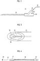
- Fig. 2 illustrates the puncture needle 15.
- the puncture needle 15 has a needle tube 51 and a base end section (needle base) 52.
- the needle tube 51 is a hollow tube that has an opening at a distal end and has a lumen inside.
- the needle tube 51 for example, is formed of metal such as stainless steel.
- the needle tube 51 for example, may be made of a fluororesin material such as polytetrafluoroethylene.
- the base end section 52 for example, is formed of a resin material such as polypropylene, polycarbonate, and polyester.
- the needle tube 51 for example, is adhered to the distal end side of the base end section 52 with an adhesive such as an epoxy resin.
- the base end section 52 has an optical fiber insertion part (optical fiber insertion port) 53 and a medicine injection portion (medicine injection port) 54.
- the optical fiber insertion part 53 for example, has a hole having a diameter of about 4 mm.
- the medicine injection portion 54 for example, has a hole having a diameter of about 6 mm to 8 mm.
- the optical fiber 61 that guides light emitted from the laser unit 13 is inserted into the inside portion of the needle tube 51 through the optical fiber insertion part 53.
- the optical fiber 61 is inside of the needle tube 51 and, for example, it is preferable that the optical fiber is stored in a tube formed of a resin material such as polyimide or is covered with a resin material to be protected.
- the medicine injection portion 54 is an injection port of liquid medicine.
- the medicine to be used for example, anesthetic, infusion, anticancer drug, ethanol, a contrast medium, and physiological saline may be considered.
- a syringe, a liquid transfusing tube, and the like are attached to the medicine injection portion 54.
- the medicine injection portion 54 may be used not only for injecting medicine but also for taking out liquid such as blood or body fluid from the subject.
- Fig. 3 illustrates a front end section of the needle tube 51.
- the needle tube 51 has an opening at a distal end. The distal end of the needle tube 51 is sharpened at an acute angle.
- a light emitting portion 62 and a light absorbing member 55 of the optical fiber 61 is arranged at the front end section of the needle tube 51.
- the light emitting portion 62 is formed by an end face on the light advancing side as seen from the laser unit 13 of the optical fiber 61.
- the light absorbing member 55 is irradiated with the light guided by the optical fiber 61 from the light emitting portion 62.
- the diameter of the optical fiber for example, is 130 ⁇ m, and for example, the light absorbing member 55 is irradiated with 2 ⁇ J of laser light from the light emitting portion 62.
- the light absorbing member 55 absorbs light emitted from the light emitting portion 62 and generates photoacoustic waves.
- an epoxy resin, a polyurethane resin, a fluororesin, or a silicone rubber, which is mixed with a black pigment may be used for the light absorbing member 55.
- metal or oxide having light absorption properties with respect to the wavelength of laser light may be used for the light absorbing member 55.
- oxide such as iron oxide, chromium oxide, or manganese oxide having high light absorption properties with respect to the wavelength of the laser light may be used.
- metal such as Ti, Pt, solder, or welded stainless steel may be used as the light absorbing member 55.
- An adhesive may be further applied on the light absorbing member 55 and cured such that the distal end thereof is fixed on to an inner wall of the needle tube 51.
- the light absorbing member 55 provided around the light emitting portion 62 is irradiated with at least a portion of the light emitted from the light emitting portion 62.
- a photoacoustic wave is generated at a distal end of the puncture needle.
- the light absorbing member 55 exists near the distal end of the puncture needle 15, and the photoacoustic waves may be generated at a point of the distal end of the puncture needle 15.
- the length of the generation source (sound source) of the photoacoustic wave is sufficiently shorter than compared with the entire length of the puncture needle, and the sound source may be regarded as a point sound source.
- the expression “near the distal end of the puncture needle 15” refers to a position at which a photoacoustic wave capable of imaging the position of the distal end of the puncture needle 15 with the accuracy necessary for a puncture operation may be generated in a case where the light emitting portion 62 and the light absorbing member 55 are arranged at this position.
- the expression refers to a portion in the range of 0 mm to 3 mm from the distal end having the opening of the puncture needle 15 to the base end section side.
- Fig. 4 illustrates the optical fiber 61 inserted from the optical fiber insertion part 53 (see Fig. 2 ).
- the light absorbing member 55 is attached to an end portion on a distal side seen from the light source of the optical fiber 61.
- the optical fiber 61 is inserted into an optical fiber insertion opening from the light absorbing member 55 side.
- the light absorbing member 55 may not be attached to a distal end of the optical fiber 61 before the insertion of the optical fiber 61.
- the light absorbing member 55 may be attached to the distal end of the optical fiber 61.
- the light absorbing member 55 may also function as a member for fixing the optical fiber 61 to the inner wall of the needle tube 51.
- An optical fiber fixing member 77 fixes the optical fiber 61 to a position spaced from the distal end (the light emitting portion 62 of Fig. 3 ) of the optical fiber 61.
- the expression "the position spaced from the distal end of the optical fiber 61" refers to a position separated from the distal end of the optical fiber 61 by a predetermined distance. It is preferable that the predetermined distance is substantially equal to the length from the distal end of the needle tube 51 to the optical fiber insertion part 53.
- the optical fiber fixing member 77 is inserted into the inside portion of the optical fiber insertion part 53.
- the optical fiber fixing member 77 is formed of at least one of a metallic material, a hard resin material, and a ceramic material.
- the optical fiber fixing member 77 for example, has a through hole in a center portion, and the optical fiber 61 is inserted into the through hole.
- the position at which the optical fiber 61 inserted into the through hole is fixed to the optical fiber fixing member 77 is determined based on the length of the needle tube 51, and the distance from the optical fiber insertion part 53 to the end portion of the needle tube 51 on the base end section 52 side.
- An optical connector 47 connected to an optical connector provided in the laser unit 13 is attached to an end portion of the optical fiber 61 on the light source side.
- a sheath 63 is a tube having flexibility and protects an optical fiber between the optical fiber fixing member 77 and the optical connector 47. It is preferable that the optical fiber 61 is covered with a polyimide resin or the like or protected by another protection tube in a predetermined range from the optical fiber fixing member 77 on the laser unit 13 side.
- the optical fiber insertion part 53 is formed such that the optical fiber insertion length may be adjusted.
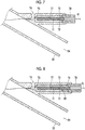
- Fig. 5 illustrates the cross section of the base end section 52 of the puncture needle 15 according to the first embodiment of the present invention.
- Fig. 6 illustrates a cross section taken along line A-A of Fig. 5 .
- Fig. 7 illustrates a cross section of the base end section 52 in a state in which the optical fiber 61 is inserted into the optical fiber insertion part 53.
- the optical fiber insertion part 53 has a through hole that communicates with the needle tube 51 (not illustrated in Fig. 5 ).
- the medicine injection portion 54 has a through hole that communicates with the needle tube 51, and the optical fiber insertion part 53 and the medicine injection portion 54 are merged in the inside portion of the base end section 52.
- the optical fiber insertion part 53 has an axis extending along a predetermined direction.
- the optical fiber insertion part 53 has a first portion 71 into which the optical fiber fixing member 77 (see Fig. 4 ) is inserted.
- the first portion 71 has a protrusion 72 that protrudes toward the center of the optical fiber insertion part 53.
- the first portion 71 has three protrusions 72 at positions spaced from each other in a circumferential direction.
- the protrusion 72 for example, is formed of a resin material.
- the protrusion 72 is formed in the inside portion of the optical fiber insertion part 53 during the injection mold.
- the number of the protrusions 72 in the first portion 71 is not limited to three, the first portion may have four or more protrusions 72.
- the shape of the cross section of the protrusion 72 is not particularly limited to Fig. 6 .
- the shape of the cross section in a case where the optical fiber insertion part 53 is cut in along the plane perpendicular to the axial direction of the optical fiber insertion part 53 at the position of the first portion 71 is not limited to a circular shape, but may be a polygonal shape such as a square or a hexagon.
- the cross section in the first portion 71 may have an oval shape or a polygonal shape such as square or hexagon.
- a protrusion formed in the first portion 71 or a wall surface of the first portion 71 comes into contact with the cross section of the optical fiber fixing member 77 at two or more points, the resistance force is sufficiently generated during the insertion of the optical fiber fixing member 77.
- the three protrusions 72 respectively extend in the insertion direction of the optical fiber.
- the size of the inside portion of the first portion 71 is reduced by the amount of the protrusion.
- the optical fiber 61 (see Fig. 4 ) is inserted into the optical fiber insertion part 53 from the distal end side thereof.
- the optical fiber fixing member 77 that fixes the optical fiber 61 is inserted into the first portion 71.
- the size of the optical fiber fixing member 77 in the direction perpendicular to the insertion direction into the first portion 71 is larger than the size of the inside portion of the first portion 71.
- the expression "the size is large” means that a diameter is large in a case where the shape is a circle or means that a length of each side is long in a case where the shape is a polygonal shape.
- the optical fiber fixing member 77 may be fixed by the protrusion 72 of the first portion 71.
- Young's modulus of the optical fiber fixing member 77 is preferably equal to or higher than Young's modulus of the first portion 71.
- At least one of at least three of protrusions 72 of the first portion 71 or the optical fiber fixing member 77 is slightly deformed to come into contact with each other, and as a result, the optical fiber fixing member 77 may be fixed by the protrusion 72 of the first portion 71.
- the size of the cross section of the optical fiber fixing member 77 in the direction perpendicular to the insertion direction into the first portion 71 is larger than the size of the diagram similar to the shape of the cross section of the optical fiber fixing member 77 that is circumscribed with the three protrusions of the first portion 71 and that is in the direction perpendicular to the insertion direction.
- a case where the shape of the optical fiber fixing member 77 in the direction perpendicular to the insertion direction into the first portion 71 has a circular shape is considered.
- a circle 76 that is circumscribed with the three protrusions 72 is considered.
- the diameter of the circle 76 is smaller than the outside diameter of the optical fiber fixing member 77.
- the diameter of the circle 76 is set as about 1.45 mm.
- the optical fiber fixing member 77 is supported by the three protrusions 72.
- the space on the inner side of the three protrusions 72 in the first portion 71 is narrower than the optical fiber fixing member 77, and thus the optical fiber fixing member 77 is required to be pushed to the first portion 71 in order to insert the optical fiber fixing member 77 into the first portion 71.
- the protrusions 72 are subjected to elastic or plastic deformation, and frictional force is generated between the protrusion 72 and the optical fiber fixing member 77.
- the buckling load of the optical fiber fixing member 77 is greater than the frictional force in a case where the optical fiber fixing member 77 is pushed to the first portion 71. Therefore, the position of the optical fiber fixing member 77 in the first portion 71 may be changed, and the insertion amount of the optical fiber fixing member 77 in the optical fiber insertion direction into the first portion 71 may be adjusted.
- the optical fiber fixing member 77 in a state in which force is not applied to the optical fiber fixing member 77, the optical fiber fixing member 77 may be temporarily fixed to the inside portion of the optical fiber insertion part 53.
- the expression "being temporarily fixed” means a state of being not completely fixed and being not displaced in the insertion direction even in a case where some force is applied.
- positions of the light emitting portion 62 or the light absorbing member 55 (see Fig. 3 ) in the front end section of the needle tube 51 may be adjusted.
- the insertion amount of the optical fiber fixing member 77 may be adjusted in the range of the length of the first portion 71 in the optical fiber insertion direction.
- the length of the first portion 71 in the optical fiber insertion direction that is, the range of adjusting the insertion amount of the optical fiber fixing member 77 is preferably longer than the length of the portion that is sharpened at an acute angle of the distal end of the needle tube 51. In this case, it is possible to arrange the light emitting portion 62 of the optical fiber 61 at any position of a portion of the distal end of the needle tube 51 which is sharpened at an acute angle.
- the optical fiber insertion part 53 has an adhesive injection port 74 in order to inject an adhesive from the outside (see Figs. 5 and 7 ).
- the adhesive injection port 74 is provided deeper than than the first portion 71 in the insertion direction of the optical fiber 61.
- the optical fiber fixing member 77 inserted into the first portion 71 is fixed to the inside portion of the optical fiber insertion part 53 with the adhesive injected from the adhesive injection port 74.
- the direction of opening the adhesive injection port 74 is not limited to this, and may be, for example, the direction perpendicular to the paper surface of Fig. 5 or 7 .
- the optical fiber insertion part 53 has a space 75 having an inner diameter larger than that of the first portion on a near sideof the insertion direction of the optical fiber 61 than the first portion 71.
- a portion of a protection tube (bush) 78 for protecting the optical fiber 61 is inserted in a certain range on the light source side from the optical fiber fixing member 77.
- the protection tube 78 is, for example, a silicone tube.
- the sheath 63 (see Fig. 4 ) for protecting the optical fiber 61 between the optical fiber fixing member 77 and the optical connector 47 is not illustrated.
- an operation of adjusting the optical fiber insertion length in the present embodiment is described.
- An operator fixes the optical fiber 61 to the optical fiber fixing member 77 by an adhesive or the like at a position spaced from a distal end of the optical fiber 61.
- the optical fiber 61 is inserted into the inside portion of the needle tube 51 (see Fig. 2 ) from the distal end side of the optical fiber 61 through the optical fiber insertion part 53, and the optical fiber fixing member 77 is inserted into the optical fiber insertion part 53.
- the operator pushes the optical fiber fixing member 77 to the first portion 71 of the optical fiber insertion part 53.
- the insertion length to the needle tube 51 of the optical fiber 61 is adjusted by changing a pushing amount of the optical fiber fixing member 77 to the first portion 71.
- the operator adjusts the insertion length of the optical fiber 61, and the light emitting portion 62 (see Fig. 3 ) at the distal end of the optical fiber 61 is arranged near the distal end of the needle tube 51.
- the optical fiber fixing member 77 is temporarily fixed to the first portion 71 by the frictional force with the protrusion 72 (see Fig. 6 ) in a stage of ending the adjustment.
- the operator injects an adhesive from the adhesive injection port 74.
- the adhesive injected from the adhesive injection port 74 flows from a space 73 (see Fig. 5 ) in the optical fiber insertion part 53 to the first portion 71.
- the first portion 71 has the three protrusion 72 at a position spaced from each other in the circumferential direction, and the adhesive flows to a gap between the optical fiber fixing member 77 temporarily fixed into the center portion of the first portion 71 and the inner wall of the optical fiber insertion part 53.
- the optical fiber fixing member 77 may be fixed to the optical fiber insertion part 53.
- the operator attaches the protection tube 78 to the light source side of the optical fiber fixing member 77 and protects the end portion of the optical fiber fixing member 77 and the optical fiber 61 with the protection tube 78.
- the operator fixes the light emitting portion 62 near the distal end of the needle tube 51.
- the light emitting portion 62 is fixed, for example, near the distal end of the needle tube 51 by the adhesive.
- the light absorbing member 55 may be attached to the light emitting portion 62 before being inserted into the needle tube 51. In this case, the light absorbing member 55 may be fixed to the front end section of the needle tube 51 by an ultraviolet curing adhesive, a light curing adhesive, or a thermosetting adhesive.
- the probe 11 is means for detecting acoustic waves and has, for example, a plurality of ultrasonic transducers one-dimensionally arranged.
- the probe 11 detects the photoacoustic wave emitted from the light absorbing member 55 (see Fig. 3 ) after the subject is punctured with the puncture needle 15.
- the probe 11 transmits acoustic waves (ultrasonic waves) to the subject and receives reflected acoustic waves (reflected ultrasonic waves) with respect to the transmitted ultrasonic waves.
- the transmission and reception of the ultrasonic waves may be performed at the separated position.
- the ultrasonic waves may be transmitted from a position different from the probe 11, and the reflected ultrasonic waves are received with the probe 11 with respect to the transmitted ultrasonic waves.
- the probe 11 is not limited to the linear probe and may be a convex probe or a sector probe.
- the ultrasonic unit 12 includes a reception circuit 21, a reception memory 22, data separation means 23, photoacoustic image generation means 24, ultrasound image generation means 25, image synthesis means 26, control means 28, and a transmission control circuit 29.
- the ultrasonic unit 12 forms a signal processing device.
- the ultrasonic unit 12 generally has a processor, a memory, a bus, and the like.
- a program relating to the photoacoustic image generation is installed in the ultrasonic unit 12, and thus the processor is operated according to the program so as to realize at least a portion of the functions of the respective units in the ultrasonic unit 12.
- the reception circuit 21 receives a detection signal output from the probe 11 and stores the received detection signal in the reception memory 22.
- the reception circuit 21 includes generally includes a low noise amplifier, a variable gain amplifier, a lowpass filter, and an Analog to Digital converter (AD converter). After the detection signal of the probe 11 is amplified by the low noise amplifier, the gain is adjusted according to the depth by the variable gain amplifier, high-frequency components are cut by the lowpass filter, and the detection signal is stored as the digital signal by the AD converter and is stored in the reception memory 22.
- the reception circuit 21 includes, for example, one Integrated Circuit (IC).
- the reception circuit 21 stores detection signal (sampling data) of the AD-converted photoacoustic waves and the reflected ultrasonic waves in the reception memory 22.
- the data separation means 23 separates sampling data of the detection signal of the photoacoustic wave stored in the reception memory 22 and the sampling data of the detection signal of the reflected ultrasonic waves.
- the data separation means 23 inputs the sampling data of the detection signal of the photoacoustic waves to the photoacoustic image generation means 24.
- the sampling data of the separated reflected ultrasonic waves is input to the ultrasound image generation means (reflected acoustic wave image generation means) 25.
- the photoacoustic image generation means 24 generates the photoacoustic image based on the detection signal of the photoacoustic waves detected by the probe 11.
- the generation of the photoacoustic image includes, for example, image reconstruction such as phase matching addition, detection, and logarithmic transformation.
- the ultrasound image generation means 25 generates the ultrasound image (reflected acoustic wave image) based on the detection signal of the reflected ultrasonic waves detected by the probe 11.
- the generation of the ultrasound image also includes image reconstruction such as phase matching addition, detection, logarithmic transformation, and the like.
- the image synthesis means 26 synthesizes the photoacoustic image and the ultrasound image.
- the image synthesis means 26 performs image synthesis, for example, by superimposing the photoacoustic image and the ultrasound image.
- the synthesized image is displayed on image display means 14 such as a display device. Without performing the image synthesis, the photoacoustic image and the ultrasound image may be displayed on the image display means 14 side by side, or the photoacoustic image and the ultrasound image may be substituted and displayed.
- the control means 28 controls the respective units in the ultrasonic unit 12.
- the trigger signal is transmitted to the laser unit 13 and the laser light is emitted from the laser unit 13.
- the sampling trigger signal is transmitted to the reception circuit 21, so as to control the sampling start timing of the photoacoustic waves or the like.
- an ultrasonic transmission trigger signal is sent to instruct the transmission control circuit 29 to transmit ultrasonic waves.
- the transmission control circuit 29 transmits ultrasonic waves from the probe 11.
- the control means 28 sends a sampling trigger signal to the reception circuit 21 according to the timing of the transmission of the ultrasonic waves and initiates the sampling of the reflected ultrasonic waves.
- the optical fiber fixing member 77 to which the optical fiber 61 is fixed is inserted into the optical fiber insertion part 53.
- the optical fiber insertion part 53 has the first portion 71 into which the optical fiber fixing member 77 is inserted, and the first portion 71 has at least three protrusions protruding toward the center in the circumferential direction at positions spaced from each other.
- the size of the optical fiber fixing member 77 in the direction perpendicular to the insertion direction with respect to the first portion 71 is greater than that of the inside portion of the first portion 71, and the optical fiber fixing member 77 is harder than the first portion 71.
- the size of the inside portion of the first portion 71 is smaller than the optical fiber fixing member 77, but the optical fiber fixing member 77 is harder than the first portion 71, and thus the optical fiber fixing member 77 may be inserted into the first portion 71.
- the distal end of the optical fiber 61 may be accurately aligned near the distal end of the needle tube 51.
- the optical fiber fixing member 77 is fixed at the adjusted position, by using an adhesive or the like.
- the size of the optical fiber fixing member 77 inserted into the first portion 71 is larger than that of the inside portion of the first portion 71. Therefore, after the adjustment of the optical fiber insertion length is completed, until the optical fiber fixing member 77 is fixed with an adhesive or the like, the optical fiber fixing member 77 is held by the frictional force working between the protrusion 72 and the optical fiber fixing member 77 in the first portion 71. Accordingly, it is possible to suppress the change of the optical fiber insertion length.
- the operator does not have to hold the optical fiber 61 in order to suppress the displacement of the optical fiber 61 and the adjustment operation is simplified.
- Fig. 8 illustrates a cross section of a base end section of the puncture needle according to the second embodiment of the present invention.
- the puncture needle according to the present embodiment further includes a metal tube 79 in which the optical fiber fixing member 77 is inserted into the inside portion.
- the optical fiber insertion part 53 (see Fig. 5 ) has a second portion 80 on a near side of the first portion 71 in the optical fiber insertion direction, in addition to the first portion 71.
- the size of the second portion 80 is larger than that of the first portion 71.
- Other points in addition to the above are the same as the first embodiment.
- the metal tube 79 has a lumen to which the optical fiber fixing member 77 is inserted into the inside portion.
- the diameter of the lumen thereof is longer than the outside diameter of the optical fiber fixing member 77.
- the diameter of the lumen of the metal tube 79 is set to be about 1.6 mm.
- the second portion 80 is a portion into which the metal tube 79 is inserted.
- the inner diameter of the second portion 80 is set to be almost the same size as the outside diameter of the metal tube 79 or smaller than the outside diameter of the metal tube 79.
- the metal tube 79 is pushed, for example, to the second portion 80.
- the metal tube 79 is fixed to the optical fiber insertion part 53 with the frictional force working between the metal tube 79 and the inner wall of the second portion 80.
- the frictional force working the inner wall thereof and the metal tube 79 is greater than the frictional force working the optical fiber fixing member 77 and the protrusion 72 in the first portion 71.
- the operator Before inserting the optical fiber 61 from the optical fiber insertion part 53 to the needle tube 51 (see Fig. 2 ), the operator inserts the metal tube 79 to the second portion 80 of the optical fiber insertion part 53. Subsequently, the operator inserts the optical fiber 61 to the needle tube 51 through the optical fiber insertion part 53 into which the metal tube 79 is inserted.
- the insertion of the optical fiber fixing member 77 into the first portion 71 is the same as described in the first embodiment.
- the operator After adjusting the insertion amount of the optical fiber fixing member 77, the operator injects an adhesive toward a gap between the metal tube 79 and the optical fiber fixing member 77 from the end portion on the light source side of the metal tube 79. Accordingly, the optical fiber fixing member 77 is instantly fixed to the metal tube 79.
- the operator injects an adhesive from the adhesive injection port 74 and fixes the optical fiber fixing member 77 to the first portion 71.
- the strength of the adhesiveness between metal by the adhesive is higher than the adhesive strength between the resin and the metal.
- the adhesive strength between the optical fiber fixing member 77 and the metal tube 79 is higher than that between the optical fiber fixing member 77 and the first portion 71.
- the puncture needle according to the present embodiment has the metal tube 79.
- the metal tube 79 is inserted into the optical fiber insertion part 53, and the insertion of the optical fiber 61 into the needle tube 51 and the insertion of the optical fiber fixing member 77 into the first portion of the optical fiber insertion part 53 are performed through the metal tube 79.
- the optical fiber fixing member 77 is firmly fixed to the metal tube 79 by using an instantaneous adhesive or the like, and thus it is possible to use a stable adhesive or the like although more time is required for curing at other bonding regions.
- the optical fiber fixing member 77 may be firmly fixed. Since the metal tube 79 may be firmly fixed for a short period of time, the frictional force between the optical fiber fixing member and the first portion 71 is set to be lower than the case of the first example, such that in a case where the front end section of the optical fiber 61 is adjusted, the fine adjustment may be performed with the smaller force. Other effects are the same as those of the first embodiment.
- an assembling method using an indirect fixing method of temporarily fixing the optical fiber fixing member 77 to the sheath 63 through the sheath 63 and fixing the sheath 63 and the optical fiber 61 there is an assembling method using an indirect fixing method of temporarily fixing the optical fiber fixing member 77 to the sheath 63 through the sheath 63 and fixing the sheath 63 and the optical fiber 61. That is, the optical fiber fixing member 77 once passes a position slightly beyond the end portion of the sheath 63. Subsequently, at a position which the optical fiber fixing member 77 passes slightly beyond the end portion of the sheath 63, for example, the optical fiber fixing member 77 is caulked by using pliers or the like to an extent that the optical fiber 61 does not break.
- the position at which the optical fiber fixing member 77 is caulked is, for example, a portion near the end portion of the optical fiber fixing member 77 on the light source side.
- the optical fiber fixing member 77 and a portion of the sheath 63 comes into contact with each other, the position of the sheath 63 (that is, the front end section of the optical fiber 61) may be adjusted while the frictional force is obtained.
- the optical fiber fixing member 77 is inserted into the first portion 71.
- two kinds of frictional force the first frictional force between the optical fiber fixing member 77 and the first portion 71 and the second frictional force between the optical fiber fixing member 77 and the sheath 63 may be used.
- the displacement of the sheath 63 with respect to the optical fiber fixing member 77 may be finely adjusted by using the second frictional force smaller than the first frictional force. This contributes to the stabilization and/or the efficiency of the assembly process.
- those described in the first embodiment or the second embodiment may be appropriately employed.
- the probe 11 detects both of the photoacoustic waves and the reflected ultrasonic waves, but the probe used in the generation of the ultrasound image and the probe used in the generation of the photoacoustic image may not be the same.
- the photoacoustic waves and the reflected ultrasonic waves may be respectively detected by independent probes. Any one of the detection (sampling) of the photoacoustic wave and the detection (sampling) of the reflected ultrasonic waves may be performed first.
- the puncture needle is not limited to the application of percutaneously puncturing the subject from the outside of the subject, but may be a needle for an ultrasonic endoscope.
- the optical fiber 61 and the light absorbing member 55 are provided on a needle for an ultrasonic endoscope, the light absorbing member 55 provided in the front end section of the needle is irradiated with light, and the photoacoustic wave is detected, so as to generate the photoacoustic image.
- puncturing may be performed while the position of the front end section of the needle for the ultrasonic endoscope is confirmed by observing the photoacoustic image.
- the photoacoustic wave generated in the front end section of the needle for the ultrasonic endoscope may be detected by using a body surface probe or may be detected using a probe incorporated in the endoscope.
- Fig. 2 an example in which the optical fiber insertion part 53 is inclined with respect to the axial direction of the needle tube 51, and the optical fiber 61 is inserted into the base end section 52 at an angle inclined with respect to the axial direction of the needle tube 51 is described, but the present invention is not limited thereto.
- the positional relationship between the optical fiber insertion part 53 and the medicine injection portion 54 is not limited to that illustrated in Fig. 2 , and any positional relationship is allowed.
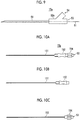
- Fig. 9 illustrates a puncture needle according to a first deformation example.
- a base end section 52a of a puncture needle 15a has the optical fiber insertion part 53 on an extension line in the axial direction of the needle tube 51, and the medicine injection portion 54 is inclined with respect to the axial direction of the needle tube 51. Also in this case, the insertion length of the optical fiber 61 may be adjusted by displacing the optical fiber fixing member 77 inserted into the optical fiber insertion part 53.
- the puncture needle 15 has the medicine injection portion 54 in the base end section 52
- the puncture needle 15 may not have to have the medicine injection portion 54.
- the inside portion of the needle tube 51, particularly, the front end section thereof, may be may be closed after the insertion of the optical fiber 61.
- the puncture needle 15 may have an inner needle and an outer needle.
- Figs. 10A, 10B, and 10C illustrate a puncture needle 15b according to the second deformation example.
- Fig. 10A illustrates an external appearance of the entire puncture needle
- Fig. 10B illustrates an external appearance of the outer needle
- Fig. 10C illustrates an external appearance of the inner needle.
- the puncture needle 15b has an outer needle 151 and an inner needle 153.
- the outer needle 151 has a lumen in the inside portion.
- the inner needle 153 has the outside diameter which is, for example, almost the same as the inner diameter of the outer needle 151, and is formed so as to be capable of being pulled in and out from the hollow outer needle 151.
- the outer needle 151 adheres to an outer needle base 152 (see Fig. 10B ), and an inner needle 153 adheres to an inner needle base 154 (see Fig. 10C ).
- the inner needle base 154 has the optical fiber insertion part 53, and the optical fiber 61 (see Fig. 2 ) is inserted into the inside portion of the inner needle 153.
- the inner needle 153 is inserted from the outer needle base 152 side into the lumen of the outer needle 151, and at least a portion of the lumen of the outer needle 151 is sealed to an extent of preventing the intrusion of a piece of the living body or the like to the lumen.
- a protrusion portion for aligning the connection position is provided in the inner needle base 154, and a groove to be engaged with the protrusion portion of the inner needle base 154 is provided in the outer needle base 152.
- the positions the protrusion of the inner needle base 154 and the groove of the outer needle base 152 are aligned, and then the inner needle base 154 is engaged with the outer needle base 152.
- Fig. 11 illustrates a cross section near the distal end of the puncture needle 15b according to a second deformation example.
- the front end sections of the outer needle 151 and the inner needle 153 are sharpened at an acute angle.
- the inner needle 153 has a tube 155 forming the needle tube.
- the optical fiber 61 is inserted into the tube of the tube 155.
- the light emitting portion 62 of the optical fiber 61 is covered with the light absorbing member 55.
- the optical fiber 61 may be inserted into the tube of the tube 155 after the light emitting portion 62 is covered with the light absorbing member 55.
- the positions of the light emitting portion 62 and the light absorbing member 55 may be adjusted with respect to the distal end (opening) of the tube 155, by adjusting the insertion length of optical fiber into the inner needle 153 (the tube 155). After the insertion length of the optical fiber 61 is adjusted, the inside portion of the tube 155 is filled with a transparent resin 156, and the optical fiber 61 is buried in the inside portion of the tube 155.
- a soft epoxy resin with less damping of the acoustic waves is used as the transparent resin 156.
- the subject is punctured with the puncture needle 15b in a state in which the inner needle 153 is set in the outer needle 151 (see Fig. 10A ). Since the lumen of the outer needle 151 is closed with the inner needle 153, it is possible to prevent a flesh piece or the like from being caught in the course of performing puncturing with the needle, and thus the hinderance of sense of the piercing by the operator may be prevented. Moisture may be prevented from flowing from the puncture region to the lumen of the outer needle 151. After puncturing the subject, the operator releases the connection between the inner needle base 154 and the outer needle base 152 and removes the inner needle 153 from the outer needle 151.
- the operator After removing the inner needle 153, the operator mounts a syringe or the like to the outer needle base 152 and injects a medicine such as an anesthetic. Otherwise, the operator takes a biopsy sample from a place of the subject which is punctured with the puncture needle 15b.
- the puncture needle is considered as the insert, but the present invention is not limited thereto.
- the insert may be a catheter to be inserted into the blood vessel.
- the insert may be an indwelling needle.
- a needle having an opening at the distal end is assumed as the needle, but the opening does not have to be provided at the front end section.
- the needle is not limited to a needle such as an injection needle and may be a biopsy needle used for biopsy. That is, the biopsy needle may be a biopsy needle capable of collecting a tissue of a biopsy region in an examination target by puncturing the examination target of a living body.
- the needle may also be used as a guiding needle for puncturing the deep portion, such as a blood vessel, subcutaneous, or internal organs inside the belly.
- the needle tube 51 and the base end section 52 do not have to be formed in an inseparable manner, and the portion of the needle tube 51 and the portion of the base end section 52 may be formed in a separable manner.
- the portion of the base end section 52 connected to the needle tube 51 is set to have a screw structure of being coupled (engaged) with a commercially available needle (needle tube), and any needles may be attachable to the base end section 52.
- the portion of the base end section 52 may be set as an attachment member that is engageable with the needle tube (hollow tube).
- a light absorbing member is attached to the optical fiber in advance.
- the operator or the like inserts a separately prepared needle into the attachment member (base end section) and adjusts the insertion amount of the optical fiber fixing member 77 (see Fig. 7 and the like) into the first portion 71, so as to adjust the position of the light absorbing member at a distal end of the needle.
- a needle having a function capable of confirming the distal end position of the needle with ultrasonic waves immediately before the operation.
- Fig. 12 illustrates the external appearance of the photoacoustic image generating device.
- the probe 11 is connected to the ultrasonic unit 12.
- the ultrasonic unit 12 is formed as an integrated device including the image display means 14.
- the ultrasonic unit 12 generally has a processor, a memory, a bus, and the like.
- a program relating to the generation of the photoacoustic image is incorporated to the ultrasonic unit 12.
- a laser unit 40 corresponds to the laser unit 13 of Fig. 1 .
- the ultrasonic unit 12 has a port 32 having a trigger signal port and a power supply port.
- a connector including a power supply input terminal 41 and a trigger input terminal 42 of the laser unit 40 is inserted into the port 32.
- the laser unit 40 may be held by being inserted into the port 32 of the ultrasonic unit 12.
- a cable including a trigger signal and a power supply line comes out from the laser unit 40 and may be connected to the ultrasonic unit 12.
- the optical connector 47 connected to a light output terminal of the laser unit 40 is arranged at one end of the optical fiber 61 forming the light guiding member of the puncture needle 15.
- the optical fiber 61 is inserted into the light output terminal without change and held by a spring force or the like.
- strong force is applied to the light output terminal due to the pulling of the puncture needle 15 by the operator, it is possible to prevent the optical fiber 61 from being fallen out from the light output terminal such that the optical fiber 61 breaks.
- the optical connector 47 does not have to be provided in the optical fiber extending from the puncture needle 15, and there is an effect of reducing the cost.
- the pulse energy of the pulsed laser light output from the laser unit 40 may be 6.4 ⁇ J in a case where the core diameter of the optical fiber 61 is 200 ⁇ m. In a case where the core diameter of the optical fiber 61 is 100 ⁇ m, the pulse energy may be 2.0 ⁇ J.
- the pulse time width may be set to 80 ns.
- the light output terminal is provided on the surface facing the surface on which the port 32 is present, but the light output terminal is preferably provided on the surface orthogonal to the surface on which the port 32 is present.
- the light output terminal is provided on the facing surface, in a case where the laser unit 40 is pulled in a case where the operator moves the puncture needle 15, the laser unit 40 is fallen out from the port 32 in some cases.
- the light output terminal is provided on the orthogonal surface, even in a case where the laser unit 40 is pulled, the laser unit 40 is hardly fallen out from the port 32.
- the trigger input signal and the power supply line may not be the same cable, and the trigger input terminal 42 may obtain a trigger signal from, for example, a connector for Electrocardiogram (ECG) synchronization which is attached to a general ultrasonic system.
- the power terminal may be taken out from the USB terminal. Otherwise, a trigger signal may be obtained from the terminal of a portion of the connector of the probe.
- ECG Electrocardiogram
Landscapes
- Health & Medical Sciences (AREA)
- Physics & Mathematics (AREA)
- Life Sciences & Earth Sciences (AREA)
- Biomedical Technology (AREA)
- Medical Informatics (AREA)
- Biophysics (AREA)
- Nuclear Medicine, Radiotherapy & Molecular Imaging (AREA)
- Pathology (AREA)
- Radiology & Medical Imaging (AREA)
- Engineering & Computer Science (AREA)
- General Physics & Mathematics (AREA)
- Heart & Thoracic Surgery (AREA)
- Optics & Photonics (AREA)
- Molecular Biology (AREA)
- Surgery (AREA)
- Animal Behavior & Ethology (AREA)
- General Health & Medical Sciences (AREA)
- Public Health (AREA)
- Veterinary Medicine (AREA)
- Ultra Sonic Daignosis Equipment (AREA)
Abstract
Description
- The present invention relates to an insert and specifically relates to an insert that includes a hollow tube and of which at least a portion is inserted into a subject. The present invention relates to an attachment member that is formed to be engageable with a hollow tube.
- An ultrasonic examination method is known as a kind of image inspection method that may non-invasively inspect the state inside a living body. In the ultrasonic examination, an ultrasound probe that may transmit and receive ultrasonic waves is used. In a case where ultrasonic waves are transmitted from an ultrasound probe to a subject (living body), the ultrasonic waves advance inside the living body, and the ultrasonic waves are reflected on a tissue interface. The reflected ultrasonic waves are received by an ultrasound probe, and a distance is calculated based on time until the reflected ultrasonic waves return to the ultrasound probe, so as to image the state of the inside.
- Photoacoustic imaging for imaging the inside of a living body by using the photoacoustic effect is known. Generally, in the photoacoustic imaging, a living body is irradiated with pulsed laser light. In the inside portion of the living body, the living tissue absorbs energy of the pulsed laser light, and ultrasonic waves (photoacoustic waves) are generated due to adiabatic expansion by the energy. In a case where photoacoustic waves are detected with an ultrasonic probe or the like, and a photoacoustic image is formed based on the detection signal, the visualization in the living body based on the photoacoustic wave may be performed.
- Here,
JP2015-037519A JP2015-037519A - In
JP2015-037519A - For example, it is considered that an optical fiber is inserted into a needle tube of a puncture needle having a length of about several tens of mm from an optical fiber insertion part (insertion opening) provided in the base end section, so as to align the distal end of the optical fiber to a portion near the distal end of the puncture needle. In this case, the position of the distal end of the optical fiber may be finely adjusted by finely adjusting the insertion length of the optical fiber.
- The distal end of the optical fiber may be fixed at a desired position by fixing the optical fiber to the insertion opening by using an adhesive or the like, after the insertion length of the optical fiber is finely adjusted. However, in a case where the inner diameter of the insertion opening of the optical fiber is longer than the diameter of the optical fiber, in a case where the hand is released from the optical fiber or the like before the optical fiber is fixed, the optical fiber may move so as to change the insertion length of the optical fiber into the hollow tube. In a case where the insertion length of the optical fiber is changed, the position of the distal end of the optical fiber moves from the position in a case of the adjustment.
- In view of the above, an object of the present invention is to provide an insert and an attachment member that is formed to be capable of suppressing the change of the insertion length of an optical fiber after the insertion length of the optical fiber to a hollow tube is adjusted.
- In order to achieve the above object, the present invention provides an insert comprising: a hollow tube of which at least a portion is inserted into a subject; an optical fiber that is inserted into an inside portion of the hollow tube and guides light emitted from a light source; a base end section including an optical fiber insertion part used for inserting the optical fiber; a light absorbing member that absorbs light guided by the optical fiber in a case of being irradiated with the light and generates a photoacoustic wave; an optical fiber fixing member that fixes the optical fiber at a position spaced from a distal end of the optical fiber and inserted into the optical fiber insertion part, in which the optical fiber insertion part includes a first portion into which the optical fiber fixing member is inserted and which has at least three protrusions protruding toward the center at positions spaced from each other in a circumferential direction, and a size of the optical fiber fixing member in a direction perpendicular to an insertion direction into the first portion is larger than that of an inside portion of the first portion, and the optical fiber fixing member is fixed by the at least three protrusions of the first portion.
- In the insert of the present invention, it is preferable that a size of a cross section of the optical fiber fixing member in the direction perpendicular to the insertion direction is larger than that of a diagram that is circumscribed with the at least three protrusions and is similar to a shape of the cross section of the optical fiber fixing member in the direction perpendicular to the insertion direction.
- In the insert of the present invention, it is preferable that the optical fiber insertion part has an axis extending along a predetermined direction. In this case, it is preferable that an insertion amount of the optical fiber fixing member into the first portion in the direction of the axis is capable of being adjusted.
- In the insert of the present invention, it is preferable that the at least three protrusions extend along the insertion direction of the optical fiber.
- In the insert of the present invention, the optical fiber insertion part may further include an adhesive injection port provided deeper than the first portion in the insertion direction of the optical fiber.
- In the insert of the present invention, the optical fiber fixing member may be fixed in the optical fiber insertion part with an adhesive injected from the adhesive injection port.
- In the insert of the present invention, it is preferable that Young's modulus of the optical fiber fixing member is the same as that of the first portion or higher than that of the first portion.
- In the insert of the present invention, the optical fiber fixing member may be formed of at least one of a metallic material, a hard resin material, or a ceramic material.
- In the insert of the present invention, the at least three protrusions may be formed of a resin material.
- The insert of the present invention further comprises a metal tube into which the optical fiber fixing member is inserted.
- In the insert, the optical fiber insertion part may include a second portion having a size larger than the size of the optical fiber fixing member on a near side of the first portion in the insertion direction of the optical fiber. In this case, the metal tube may be inserted into the second portion.
- It is preferable that a size of the inside portion of the metal tube is larger than the size of the optical fiber fixing member.
- In the insert of the present invention, the hollow tube may have an opening at a distal end, and the distal end of the hollow tube may be sharpened at an acute angle.
- In the insert of the present invention, it is preferable that a length of the first portion in the insertion direction of the optical fiber is longer than that of the portion of the distal end of the hollow tube which is sharpened at an acute angle.
- The present invention also provides an attachment member which is engageable with a hollow tube of which at least a portion is inserted into a subject, the attachment member comprising: an optical fiber that is inserted into an inside portion of the hollow tube in a case where the hollow tube is engaged and guides light emitted from a light source; a base end section including an optical fiber insertion part used for inserting the optical fiber; and an optical fiber fixing member that fixes the optical fiber at a position spaced from a distal end of the optical fiber and is inserted into the optical fiber insertion part, the optical fiber insertion part includes a first portion into which the optical fiber fixing member is inserted and which has at least three protrusions protruding toward the center at positions spaced from each other in a circumferential direction, and a size of the optical fiber fixing member in a direction perpendicular to an insertion direction into the first portion is larger than that of an inside portion of the first portion, and the optical fiber fixing member is fixed by the at least three protrusions of the first portion.
- An insert and an attachment member of the present invention may suppress a change in an insertion length of an optical fiber after adjusting an insertion length of the optical fiber with respect to the hollow tube.
-
-
Fig. 1 is a block diagram illustrating a photoacoustic image generating device used in an insert according to a first embodiment of the present invention. -
Fig. 2 is a side view illustrating a puncture needle. -
Fig. 3 is a front view illustrating a front end section of a needle tube in a puncture needle. -
Fig. 4 is a drawing illustrating an optical fiber inserted from an optical fiber insertion part. -
Fig. 5 is a cross sectional view illustrating a base end section of a puncture needle according to the first embodiment of the present invention. -
Fig. 6 is a cross sectional view illustrating a cross section taken along line A-A ofFig. 5 . -
Fig. 7 is a cross sectional view illustrating a base end section in a state in which an optical fiber is inserted into an optical fiber insertion part. -
Fig. 8 is a cross sectional view illustrating a base end section of a puncture needle of a second embodiment of the present invention. -
Fig. 9 is a side view illustrating a puncture needle according to a first deformation example. -
Fig. 10A is a diagram illustrating an external appearance of an entire puncture needle of a second deformation example. -
Fig. 10B is a diagram illustrating an external appearance of an outer needle. -
Fig. 10C is a diagram illustrating an external appearance of an inner needle. -
Fig. 11 is a cross sectional view illustrating a distal end of a puncture needle according to the second deformation example. -
Fig. 12 is a perspective view illustrating an external appearance of a photoacoustic image generating device. - Hereinafter, embodiments of the present invention will be described in detail with reference to the drawings.
Fig. 1 illustrates a photoacoustic image generating device used in an insert according to a first embodiment of the present invention. A photoacoustic image generating device (photoacoustic image diagnostic device) 10 includes a probe (ultrasound probe) 11, anultrasonic unit 12, alaser unit 13, and apuncture needle 15. According to the embodiment of the present invention, ultrasonic waves are used as the acoustic waves, but the present invention is not limited to ultrasonic waves. An acoustic wave of an audible frequency may be used as long as an appropriate frequency may be selected according to a subject to be examined, measurement conditions, or the like. - The
laser unit 13 is a light source. Thelaser unit 13 is, for example, a laser diode light source (semiconductor laser light source). Otherwise, thelaser unit 13 may be a light amplification type laser light source using a laser diode light source as a seed light source. A type of the laser light source used in thelaser unit 13 is not particularly limited, and a solid-state laser light source using, for example, yttrium-aluminum-garnet (YAG), alexandrite, or the like may be used for thelaser unit 13. The laser light emitted from thelaser unit 13, for example, is guided to thepuncture needle 15 by using light guiding means such as anoptical fiber 61. A light source other than the laser light source may be used. - According to the present embodiment, the
puncture needle 15 that includes a hollow tube and may be used for injection of medicine or the like is considered as an insert of which at least a portion is inserted into the subject is considered.Fig. 2 illustrates thepuncture needle 15. Thepuncture needle 15 has aneedle tube 51 and a base end section (needle base) 52. Theneedle tube 51 is a hollow tube that has an opening at a distal end and has a lumen inside. Theneedle tube 51, for example, is formed of metal such as stainless steel. Theneedle tube 51, for example, may be made of a fluororesin material such as polytetrafluoroethylene. Thebase end section 52, for example, is formed of a resin material such as polypropylene, polycarbonate, and polyester. Theneedle tube 51, for example, is adhered to the distal end side of thebase end section 52 with an adhesive such as an epoxy resin. - The
base end section 52 has an optical fiber insertion part (optical fiber insertion port) 53 and a medicine injection portion (medicine injection port) 54. The opticalfiber insertion part 53, for example, has a hole having a diameter of about 4 mm. Themedicine injection portion 54, for example, has a hole having a diameter of about 6 mm to 8 mm. Theoptical fiber 61 that guides light emitted from thelaser unit 13 is inserted into the inside portion of theneedle tube 51 through the opticalfiber insertion part 53. Theoptical fiber 61 is inside of theneedle tube 51 and, for example, it is preferable that the optical fiber is stored in a tube formed of a resin material such as polyimide or is covered with a resin material to be protected. - The
medicine injection portion 54 is an injection port of liquid medicine. As the medicine to be used, for example, anesthetic, infusion, anticancer drug, ethanol, a contrast medium, and physiological saline may be considered. A syringe, a liquid transfusing tube, and the like are attached to themedicine injection portion 54. Themedicine injection portion 54 may be used not only for injecting medicine but also for taking out liquid such as blood or body fluid from the subject. -
Fig. 3 illustrates a front end section of theneedle tube 51. Theneedle tube 51 has an opening at a distal end. The distal end of theneedle tube 51 is sharpened at an acute angle. Alight emitting portion 62 and alight absorbing member 55 of theoptical fiber 61 is arranged at the front end section of theneedle tube 51. Thelight emitting portion 62 is formed by an end face on the light advancing side as seen from thelaser unit 13 of theoptical fiber 61. Thelight absorbing member 55 is irradiated with the light guided by theoptical fiber 61 from thelight emitting portion 62. The diameter of the optical fiber, for example, is 130 µm, and for example, thelight absorbing member 55 is irradiated with 2 µJ of laser light from thelight emitting portion 62. - The
light absorbing member 55 absorbs light emitted from thelight emitting portion 62 and generates photoacoustic waves. For example, an epoxy resin, a polyurethane resin, a fluororesin, or a silicone rubber, which is mixed with a black pigment may be used for thelight absorbing member 55. Otherwise, metal or oxide having light absorption properties with respect to the wavelength of laser light may be used for thelight absorbing member 55. For example, as thelight absorbing member 55, oxide such as iron oxide, chromium oxide, or manganese oxide having high light absorption properties with respect to the wavelength of the laser light may be used. Otherwise, metal such as Ti, Pt, solder, or welded stainless steel may be used as thelight absorbing member 55. An adhesive may be further applied on thelight absorbing member 55 and cured such that the distal end thereof is fixed on to an inner wall of theneedle tube 51. - The
light absorbing member 55 provided around thelight emitting portion 62 is irradiated with at least a portion of the light emitted from thelight emitting portion 62. In a case where thelight absorbing member 55 absorbs the irradiated light, a photoacoustic wave is generated at a distal end of the puncture needle. Thelight absorbing member 55 exists near the distal end of thepuncture needle 15, and the photoacoustic waves may be generated at a point of the distal end of thepuncture needle 15. The length of the generation source (sound source) of the photoacoustic wave is sufficiently shorter than compared with the entire length of the puncture needle, and the sound source may be regarded as a point sound source. Here, the expression "near the distal end of thepuncture needle 15" refers to a position at which a photoacoustic wave capable of imaging the position of the distal end of thepuncture needle 15 with the accuracy necessary for a puncture operation may be generated in a case where thelight emitting portion 62 and thelight absorbing member 55 are arranged at this position. For example, the expression refers to a portion in the range of 0 mm to 3 mm from the distal end having the opening of thepuncture needle 15 to the base end section side. -
Fig. 4 illustrates theoptical fiber 61 inserted from the optical fiber insertion part 53 (seeFig. 2 ). Thelight absorbing member 55 is attached to an end portion on a distal side seen from the light source of theoptical fiber 61. Theoptical fiber 61 is inserted into an optical fiber insertion opening from thelight absorbing member 55 side. Thelight absorbing member 55 may not be attached to a distal end of theoptical fiber 61 before the insertion of theoptical fiber 61. After theoptical fiber 61 is inserted into theneedle tube 51, thelight absorbing member 55 may be attached to the distal end of theoptical fiber 61. In this case, thelight absorbing member 55 may also function as a member for fixing theoptical fiber 61 to the inner wall of theneedle tube 51. - An optical
fiber fixing member 77 fixes theoptical fiber 61 to a position spaced from the distal end (thelight emitting portion 62 ofFig. 3 ) of theoptical fiber 61. Here, the expression "the position spaced from the distal end of theoptical fiber 61", for example, refers to a position separated from the distal end of theoptical fiber 61 by a predetermined distance. It is preferable that the predetermined distance is substantially equal to the length from the distal end of theneedle tube 51 to the opticalfiber insertion part 53. In a case where theoptical fiber 61 is fixed at a position at which the opticalfiber fixing member 77 is spaced from such a distance, in a case where the distal end of theoptical fiber 61 comes close to the distal end of theneedle tube 51, the opticalfiber fixing member 77 is inserted into the inside portion of the opticalfiber insertion part 53. - The optical
fiber fixing member 77, for example, is formed of at least one of a metallic material, a hard resin material, and a ceramic material. The opticalfiber fixing member 77, for example, has a through hole in a center portion, and theoptical fiber 61 is inserted into the through hole. The position at which theoptical fiber 61 inserted into the through hole is fixed to the opticalfiber fixing member 77 is determined based on the length of theneedle tube 51, and the distance from the opticalfiber insertion part 53 to the end portion of theneedle tube 51 on thebase end section 52 side. - An
optical connector 47 connected to an optical connector provided in thelaser unit 13 is attached to an end portion of theoptical fiber 61 on the light source side. Asheath 63 is a tube having flexibility and protects an optical fiber between the opticalfiber fixing member 77 and theoptical connector 47. It is preferable that theoptical fiber 61 is covered with a polyimide resin or the like or protected by another protection tube in a predetermined range from the opticalfiber fixing member 77 on thelaser unit 13 side. - In the
puncture needle 15 of the present embodiment, in order to accurately align thelight emitting portion 62 of theoptical fiber 61 near the distal end of theneedle tube 51, the opticalfiber insertion part 53 is formed such that the optical fiber insertion length may be adjusted.Fig. 5 illustrates the cross section of thebase end section 52 of thepuncture needle 15 according to the first embodiment of the present invention.Fig. 6 illustrates a cross section taken along line A-A ofFig. 5 .Fig. 7 illustrates a cross section of thebase end section 52 in a state in which theoptical fiber 61 is inserted into the opticalfiber insertion part 53. As illustrated inFig. 5 , the opticalfiber insertion part 53 has a through hole that communicates with the needle tube 51 (not illustrated inFig. 5 ). Themedicine injection portion 54 has a through hole that communicates with theneedle tube 51, and the opticalfiber insertion part 53 and themedicine injection portion 54 are merged in the inside portion of thebase end section 52. - The optical
fiber insertion part 53 has an axis extending along a predetermined direction. The opticalfiber insertion part 53 has afirst portion 71 into which the optical fiber fixing member 77 (seeFig. 4 ) is inserted. Thefirst portion 71 has aprotrusion 72 that protrudes toward the center of the opticalfiber insertion part 53. As illustrated inFig. 6 , thefirst portion 71 has threeprotrusions 72 at positions spaced from each other in a circumferential direction. Theprotrusion 72, for example, is formed of a resin material. For example, in a case where a main body portion of thebase end section 52 is formed by injection mold, theprotrusion 72 is formed in the inside portion of the opticalfiber insertion part 53 during the injection mold. - The number of the
protrusions 72 in thefirst portion 71 is not limited to three, the first portion may have four ormore protrusions 72. The shape of the cross section of theprotrusion 72 is not particularly limited toFig. 6 . The shape of the cross section in a case where the opticalfiber insertion part 53 is cut in along the plane perpendicular to the axial direction of the opticalfiber insertion part 53 at the position of thefirst portion 71 is not limited to a circular shape, but may be a polygonal shape such as a square or a hexagon. - Instead of using the
protrusion 72 in thefirst portion 71, the cross section in thefirst portion 71 may have an oval shape or a polygonal shape such as square or hexagon. In short, in a case where a cross sectional area of thefirst portion 71 is larger than a cross sectional area of the opticalfiber fixing member 77, a protrusion formed in thefirst portion 71 or a wall surface of thefirst portion 71 comes into contact with the cross section of the opticalfiber fixing member 77 at two or more points, the resistance force is sufficiently generated during the insertion of the opticalfiber fixing member 77. - In the
first portion 71, the threeprotrusions 72 respectively extend in the insertion direction of the optical fiber. In thefirst portion 71, since theprotrusion 72 protrudes to the inside portion, the size of the inside portion of thefirst portion 71 is reduced by the amount of the protrusion. The optical fiber 61 (seeFig. 4 ) is inserted into the opticalfiber insertion part 53 from the distal end side thereof. In a case where theoptical fiber 61 is inserted into theneedle tube 51 from the opticalfiber insertion part 53, the opticalfiber fixing member 77 that fixes theoptical fiber 61 is inserted into thefirst portion 71. - According to the present embodiment, the size of the optical
fiber fixing member 77 in the direction perpendicular to the insertion direction into thefirst portion 71 is larger than the size of the inside portion of thefirst portion 71. For example, the expression "the size is large" means that a diameter is large in a case where the shape is a circle or means that a length of each side is long in a case where the shape is a polygonal shape. Accordingly, the opticalfiber fixing member 77 may be fixed by theprotrusion 72 of thefirst portion 71. According to the present embodiment, Young's modulus of the opticalfiber fixing member 77 is preferably equal to or higher than Young's modulus of thefirst portion 71. Accordingly, at least one of at least three ofprotrusions 72 of thefirst portion 71 or the opticalfiber fixing member 77 is slightly deformed to come into contact with each other, and as a result, the opticalfiber fixing member 77 may be fixed by theprotrusion 72 of thefirst portion 71. - According to the present embodiment, the size of the cross section of the optical
fiber fixing member 77 in the direction perpendicular to the insertion direction into thefirst portion 71 is larger than the size of the diagram similar to the shape of the cross section of the opticalfiber fixing member 77 that is circumscribed with the three protrusions of thefirst portion 71 and that is in the direction perpendicular to the insertion direction. For example, a case where the shape of the opticalfiber fixing member 77 in the direction perpendicular to the insertion direction into thefirst portion 71 has a circular shape is considered. In thefirst portion 71, as illustrated inFig. 6 , acircle 76 that is circumscribed with the threeprotrusions 72 is considered. In this case, the diameter of thecircle 76 is smaller than the outside diameter of the opticalfiber fixing member 77. Specifically, for example, in a case where the outside diameter of the opticalfiber fixing member 77 is about 1.5 mm, the diameter of thecircle 76 is set as about 1.45 mm. - According to the present embodiment, in the
first portion 71, the opticalfiber fixing member 77 is supported by the threeprotrusions 72. The space on the inner side of the threeprotrusions 72 in thefirst portion 71 is narrower than the opticalfiber fixing member 77, and thus the opticalfiber fixing member 77 is required to be pushed to thefirst portion 71 in order to insert the opticalfiber fixing member 77 into thefirst portion 71. In a case where the opticalfiber fixing member 77 is pushed to thefirst portion 71, theprotrusions 72 are subjected to elastic or plastic deformation, and frictional force is generated between theprotrusion 72 and the opticalfiber fixing member 77. - According to the present embodiment, the buckling load of the optical
fiber fixing member 77 is greater than the frictional force in a case where the opticalfiber fixing member 77 is pushed to thefirst portion 71. Therefore, the position of the opticalfiber fixing member 77 in thefirst portion 71 may be changed, and the insertion amount of the opticalfiber fixing member 77 in the optical fiber insertion direction into thefirst portion 71 may be adjusted. In a case where frictional force works between the opticalfiber fixing member 77 and theprotrusion 72 in thefirst portion 71, in a state in which force is not applied to the opticalfiber fixing member 77, the opticalfiber fixing member 77 may be temporarily fixed to the inside portion of the opticalfiber insertion part 53. Here, the expression "being temporarily fixed" means a state of being not completely fixed and being not displaced in the insertion direction even in a case where some force is applied. - According to the present embodiment, in a case where the insertion amount of the optical
fiber fixing member 77 is adjusted, positions of thelight emitting portion 62 or the light absorbing member 55 (seeFig. 3 ) in the front end section of theneedle tube 51 may be adjusted. The insertion amount of the opticalfiber fixing member 77 may be adjusted in the range of the length of thefirst portion 71 in the optical fiber insertion direction. The length of thefirst portion 71 in the optical fiber insertion direction, that is, the range of adjusting the insertion amount of the opticalfiber fixing member 77 is preferably longer than the length of the portion that is sharpened at an acute angle of the distal end of theneedle tube 51. In this case, it is possible to arrange thelight emitting portion 62 of theoptical fiber 61 at any position of a portion of the distal end of theneedle tube 51 which is sharpened at an acute angle. - The optical
fiber insertion part 53 has anadhesive injection port 74 in order to inject an adhesive from the outside (seeFigs. 5 and7 ). Theadhesive injection port 74 is provided deeper than than thefirst portion 71 in the insertion direction of theoptical fiber 61. The opticalfiber fixing member 77 inserted into thefirst portion 71 is fixed to the inside portion of the opticalfiber insertion part 53 with the adhesive injected from theadhesive injection port 74. The direction of opening theadhesive injection port 74 is not limited to this, and may be, for example, the direction perpendicular to the paper surface ofFig. 5 or7 . - The optical
fiber insertion part 53 has aspace 75 having an inner diameter larger than that of the first portion on a near sideof the insertion direction of theoptical fiber 61 than thefirst portion 71. As illustrated inFig. 7 , in thespace 75, a portion of a protection tube (bush) 78 for protecting theoptical fiber 61 is inserted in a certain range on the light source side from the opticalfiber fixing member 77. Theprotection tube 78 is, for example, a silicone tube. InFig. 7 , the sheath 63 (seeFig. 4 ) for protecting theoptical fiber 61 between the opticalfiber fixing member 77 and theoptical connector 47 is not illustrated. - Subsequently, an operation of adjusting the optical fiber insertion length in the present embodiment is described. An operator fixes the
optical fiber 61 to the opticalfiber fixing member 77 by an adhesive or the like at a position spaced from a distal end of theoptical fiber 61. Subsequently, theoptical fiber 61 is inserted into the inside portion of the needle tube 51 (seeFig. 2 ) from the distal end side of theoptical fiber 61 through the opticalfiber insertion part 53, and the opticalfiber fixing member 77 is inserted into the opticalfiber insertion part 53. - The operator pushes the optical
fiber fixing member 77 to thefirst portion 71 of the opticalfiber insertion part 53. The insertion length to theneedle tube 51 of theoptical fiber 61 is adjusted by changing a pushing amount of the opticalfiber fixing member 77 to thefirst portion 71. The operator adjusts the insertion length of theoptical fiber 61, and the light emitting portion 62 (seeFig. 3 ) at the distal end of theoptical fiber 61 is arranged near the distal end of theneedle tube 51. The opticalfiber fixing member 77 is temporarily fixed to thefirst portion 71 by the frictional force with the protrusion 72 (seeFig. 6 ) in a stage of ending the adjustment. - After the operator adjusts the insertion amount of the
optical fiber 61, the operator injects an adhesive from theadhesive injection port 74. The adhesive injected from theadhesive injection port 74 flows from a space 73 (seeFig. 5 ) in the opticalfiber insertion part 53 to thefirst portion 71. As illustrated inFig. 6 , thefirst portion 71 has the threeprotrusion 72 at a position spaced from each other in the circumferential direction, and the adhesive flows to a gap between the opticalfiber fixing member 77 temporarily fixed into the center portion of thefirst portion 71 and the inner wall of the opticalfiber insertion part 53. In a case where the adhesive flowing to the gap is cured, the opticalfiber fixing member 77 may be fixed to the opticalfiber insertion part 53. After the opticalfiber fixing member 77 is fixed, the operator attaches theprotection tube 78 to the light source side of the opticalfiber fixing member 77 and protects the end portion of the opticalfiber fixing member 77 and theoptical fiber 61 with theprotection tube 78. - In a case where the position of the
light emitting portion 62 is positioned at a desired position near the distal end of theneedle tube 51, the operator fixes thelight emitting portion 62 near the distal end of theneedle tube 51. Thelight emitting portion 62 is fixed, for example, near the distal end of theneedle tube 51 by the adhesive. The light absorbing member 55 (seeFig. 4 ) may be attached to thelight emitting portion 62 before being inserted into theneedle tube 51. In this case, thelight absorbing member 55 may be fixed to the front end section of theneedle tube 51 by an ultraviolet curing adhesive, a light curing adhesive, or a thermosetting adhesive. - Returning to
Fig. 1 , theprobe 11 is means for detecting acoustic waves and has, for example, a plurality of ultrasonic transducers one-dimensionally arranged. Theprobe 11 detects the photoacoustic wave emitted from the light absorbing member 55 (seeFig. 3 ) after the subject is punctured with thepuncture needle 15. In addition to the detection of the photoacoustic wave, theprobe 11 transmits acoustic waves (ultrasonic waves) to the subject and receives reflected acoustic waves (reflected ultrasonic waves) with respect to the transmitted ultrasonic waves. The transmission and reception of the ultrasonic waves may be performed at the separated position. For example, the ultrasonic waves may be transmitted from a position different from theprobe 11, and the reflected ultrasonic waves are received with theprobe 11 with respect to the transmitted ultrasonic waves. Theprobe 11 is not limited to the linear probe and may be a convex probe or a sector probe. - The
ultrasonic unit 12 includes areception circuit 21, areception memory 22, data separation means 23, photoacoustic image generation means 24, ultrasound image generation means 25, image synthesis means 26, control means 28, and atransmission control circuit 29. Theultrasonic unit 12 forms a signal processing device. Theultrasonic unit 12 generally has a processor, a memory, a bus, and the like. A program relating to the photoacoustic image generation is installed in theultrasonic unit 12, and thus the processor is operated according to the program so as to realize at least a portion of the functions of the respective units in theultrasonic unit 12. - The
reception circuit 21 receives a detection signal output from theprobe 11 and stores the received detection signal in thereception memory 22. Thereception circuit 21 includes generally includes a low noise amplifier, a variable gain amplifier, a lowpass filter, and an Analog to Digital converter (AD converter). After the detection signal of theprobe 11 is amplified by the low noise amplifier, the gain is adjusted according to the depth by the variable gain amplifier, high-frequency components are cut by the lowpass filter, and the detection signal is stored as the digital signal by the AD converter and is stored in thereception memory 22. Thereception circuit 21 includes, for example, one Integrated Circuit (IC). - The
reception circuit 21 stores detection signal (sampling data) of the AD-converted photoacoustic waves and the reflected ultrasonic waves in thereception memory 22. The data separation means 23 separates sampling data of the detection signal of the photoacoustic wave stored in thereception memory 22 and the sampling data of the detection signal of the reflected ultrasonic waves. The data separation means 23 inputs the sampling data of the detection signal of the photoacoustic waves to the photoacoustic image generation means 24. The sampling data of the separated reflected ultrasonic waves is input to the ultrasound image generation means (reflected acoustic wave image generation means) 25. - The photoacoustic image generation means 24 generates the photoacoustic image based on the detection signal of the photoacoustic waves detected by the
probe 11. The generation of the photoacoustic image includes, for example, image reconstruction such as phase matching addition, detection, and logarithmic transformation. The ultrasound image generation means 25 generates the ultrasound image (reflected acoustic wave image) based on the detection signal of the reflected ultrasonic waves detected by theprobe 11. The generation of the ultrasound image also includes image reconstruction such as phase matching addition, detection, logarithmic transformation, and the like. - The image synthesis means 26 synthesizes the photoacoustic image and the ultrasound image. The image synthesis means 26 performs image synthesis, for example, by superimposing the photoacoustic image and the ultrasound image. The synthesized image is displayed on image display means 14 such as a display device. Without performing the image synthesis, the photoacoustic image and the ultrasound image may be displayed on the image display means 14 side by side, or the photoacoustic image and the ultrasound image may be substituted and displayed.
- The control means 28 controls the respective units in the
ultrasonic unit 12. In a case where the control means 28 obtains, for example, the photoacoustic image, the trigger signal is transmitted to thelaser unit 13 and the laser light is emitted from thelaser unit 13. According to the emission of the laser light, the sampling trigger signal is transmitted to thereception circuit 21, so as to control the sampling start timing of the photoacoustic waves or the like. - In a case where the control means 28 obtains the ultrasound image, an ultrasonic transmission trigger signal is sent to instruct the
transmission control circuit 29 to transmit ultrasonic waves. In a case where the ultrasonic transmission trigger signal is received, thetransmission control circuit 29 transmits ultrasonic waves from theprobe 11. The control means 28 sends a sampling trigger signal to thereception circuit 21 according to the timing of the transmission of the ultrasonic waves and initiates the sampling of the reflected ultrasonic waves. - According to the present embodiment, the optical
fiber fixing member 77 to which theoptical fiber 61 is fixed is inserted into the opticalfiber insertion part 53. The opticalfiber insertion part 53 has thefirst portion 71 into which the opticalfiber fixing member 77 is inserted, and thefirst portion 71 has at least three protrusions protruding toward the center in the circumferential direction at positions spaced from each other. According to the present embodiment, the size of the opticalfiber fixing member 77 in the direction perpendicular to the insertion direction with respect to thefirst portion 71 is greater than that of the inside portion of thefirst portion 71, and the opticalfiber fixing member 77 is harder than thefirst portion 71. The size of the inside portion of thefirst portion 71 is smaller than the opticalfiber fixing member 77, but the opticalfiber fixing member 77 is harder than thefirst portion 71, and thus the opticalfiber fixing member 77 may be inserted into thefirst portion 71. In a case where the insertion amount of the opticalfiber fixing member 77 into thefirst portion 71 is adjusted, the distal end of theoptical fiber 61 may be accurately aligned near the distal end of theneedle tube 51. - According to the present embodiment, after the optical fiber insertion length is adjusted, the optical
fiber fixing member 77 is fixed at the adjusted position, by using an adhesive or the like. According to the present embodiment, the size of the opticalfiber fixing member 77 inserted into thefirst portion 71 is larger than that of the inside portion of thefirst portion 71. Therefore, after the adjustment of the optical fiber insertion length is completed, until the opticalfiber fixing member 77 is fixed with an adhesive or the like, the opticalfiber fixing member 77 is held by the frictional force working between theprotrusion 72 and the opticalfiber fixing member 77 in thefirst portion 71. Accordingly, it is possible to suppress the change of the optical fiber insertion length. According to the present embodiment, after the optical fiber insertion length is adjusted, until the opticalfiber fixing member 77 is fixed, the operator does not have to hold theoptical fiber 61 in order to suppress the displacement of theoptical fiber 61 and the adjustment operation is simplified. - Subsequently, a second embodiment of the present invention is described.
Fig. 8 illustrates a cross section of a base end section of the puncture needle according to the second embodiment of the present invention. The puncture needle according to the present embodiment further includes ametal tube 79 in which the opticalfiber fixing member 77 is inserted into the inside portion. The optical fiber insertion part 53 (seeFig. 5 ) has asecond portion 80 on a near side of thefirst portion 71 in the optical fiber insertion direction, in addition to thefirst portion 71. The size of thesecond portion 80 is larger than that of thefirst portion 71. Other points in addition to the above are the same as the first embodiment. - The
metal tube 79 has a lumen to which the opticalfiber fixing member 77 is inserted into the inside portion. The diameter of the lumen thereof is longer than the outside diameter of the opticalfiber fixing member 77. For example, in a case where the outside diameter of the opticalfiber fixing member 77 is about 1.4 mm, the diameter of the lumen of themetal tube 79 is set to be about 1.6 mm. Thesecond portion 80 is a portion into which themetal tube 79 is inserted. The inner diameter of thesecond portion 80 is set to be almost the same size as the outside diameter of themetal tube 79 or smaller than the outside diameter of themetal tube 79. Themetal tube 79 is pushed, for example, to thesecond portion 80. Themetal tube 79 is fixed to the opticalfiber insertion part 53 with the frictional force working between themetal tube 79 and the inner wall of thesecond portion 80. In thesecond portion 80, the frictional force working the inner wall thereof and themetal tube 79 is greater than the frictional force working the opticalfiber fixing member 77 and theprotrusion 72 in thefirst portion 71. - Before inserting the
optical fiber 61 from the opticalfiber insertion part 53 to the needle tube 51 (seeFig. 2 ), the operator inserts themetal tube 79 to thesecond portion 80 of the opticalfiber insertion part 53. Subsequently, the operator inserts theoptical fiber 61 to theneedle tube 51 through the opticalfiber insertion part 53 into which themetal tube 79 is inserted. The insertion of the opticalfiber fixing member 77 into thefirst portion 71 is the same as described in the first embodiment. - After adjusting the insertion amount of the optical
fiber fixing member 77, the operator injects an adhesive toward a gap between themetal tube 79 and the opticalfiber fixing member 77 from the end portion on the light source side of themetal tube 79. Accordingly, the opticalfiber fixing member 77 is instantly fixed to themetal tube 79. The operator injects an adhesive from theadhesive injection port 74 and fixes the opticalfiber fixing member 77 to thefirst portion 71. Generally, the strength of the adhesiveness between metal by the adhesive is higher than the adhesive strength between the resin and the metal. In a case where the opticalfiber fixing member 77 is formed of metal, the adhesive strength between the opticalfiber fixing member 77 and themetal tube 79 is higher than that between the opticalfiber fixing member 77 and thefirst portion 71. After fixing the opticalfiber fixing member 77, the operator attaches theprotection tube 78 to the light source side than the opticalfiber fixing member 77 and protects the end portion of the opticalfiber fixing member 77 and theoptical fiber 61 with theprotection tube 78. - The puncture needle according to the present embodiment has the
metal tube 79. Themetal tube 79 is inserted into the opticalfiber insertion part 53, and the insertion of theoptical fiber 61 into theneedle tube 51 and the insertion of the opticalfiber fixing member 77 into the first portion of the opticalfiber insertion part 53 are performed through themetal tube 79. After the insertion amount of the opticalfiber fixing member 77 into thefirst portion 71 is adjusted, the opticalfiber fixing member 77 is firmly fixed to themetal tube 79 by using an instantaneous adhesive or the like, and thus it is possible to use a stable adhesive or the like although more time is required for curing at other bonding regions. In a case where the adhesive injected to thefirst portion 71 is cured and then stopped by themetal tube 79, the opticalfiber fixing member 77 may be firmly fixed. Since themetal tube 79 may be firmly fixed for a short period of time, the frictional force between the optical fiber fixing member and thefirst portion 71 is set to be lower than the case of the first example, such that in a case where the front end section of theoptical fiber 61 is adjusted, the fine adjustment may be performed with the smaller force. Other effects are the same as those of the first embodiment. - As an assembling method according to the derivative form of the above embodiment, there is an assembling method using an indirect fixing method of temporarily fixing the optical
fiber fixing member 77 to thesheath 63 through thesheath 63 and fixing thesheath 63 and theoptical fiber 61. That is, the opticalfiber fixing member 77 once passes a position slightly beyond the end portion of thesheath 63. Subsequently, at a position which the opticalfiber fixing member 77 passes slightly beyond the end portion of thesheath 63, for example, the opticalfiber fixing member 77 is caulked by using pliers or the like to an extent that theoptical fiber 61 does not break. The position at which the opticalfiber fixing member 77 is caulked is, for example, a portion near the end portion of the opticalfiber fixing member 77 on the light source side. In this caulking step, the opticalfiber fixing member 77 and a portion of thesheath 63 comes into contact with each other, the position of the sheath 63 (that is, the front end section of the optical fiber 61) may be adjusted while the frictional force is obtained. In this state, the opticalfiber fixing member 77 is inserted into thefirst portion 71. - According to the assembling method according to the derivative form of the above embodiment, two kinds of frictional force: the first frictional force between the optical
fiber fixing member 77 and thefirst portion 71 and the second frictional force between the opticalfiber fixing member 77 and thesheath 63 may be used. With respect to the effects, for example, in a case where the unevenness of the first frictional force is greater than the tolerance of resin form, after the position of the opticalfiber fixing member 77 with respect to thefirst portion 71 is roughly adjusted, the displacement of thesheath 63 with respect to the opticalfiber fixing member 77 may be finely adjusted by using the second frictional force smaller than the first frictional force. This contributes to the stabilization and/or the efficiency of the assembly process. As the assembling method after the fiber insertion amount is adjusted, those described in the first embodiment or the second embodiment may be appropriately employed. - In the respective embodiments, it is described that the
probe 11 detects both of the photoacoustic waves and the reflected ultrasonic waves, but the probe used in the generation of the ultrasound image and the probe used in the generation of the photoacoustic image may not be the same. The photoacoustic waves and the reflected ultrasonic waves may be respectively detected by independent probes. Any one of the detection (sampling) of the photoacoustic wave and the detection (sampling) of the reflected ultrasonic waves may be performed first. - The puncture needle is not limited to the application of percutaneously puncturing the subject from the outside of the subject, but may be a needle for an ultrasonic endoscope. The
optical fiber 61 and thelight absorbing member 55 are provided on a needle for an ultrasonic endoscope, thelight absorbing member 55 provided in the front end section of the needle is irradiated with light, and the photoacoustic wave is detected, so as to generate the photoacoustic image. In this case, puncturing may be performed while the position of the front end section of the needle for the ultrasonic endoscope is confirmed by observing the photoacoustic image. The photoacoustic wave generated in the front end section of the needle for the ultrasonic endoscope may be detected by using a body surface probe or may be detected using a probe incorporated in the endoscope. - In
Fig. 2 , an example in which the opticalfiber insertion part 53 is inclined with respect to the axial direction of theneedle tube 51, and theoptical fiber 61 is inserted into thebase end section 52 at an angle inclined with respect to the axial direction of theneedle tube 51 is described, but the present invention is not limited thereto. The positional relationship between the opticalfiber insertion part 53 and themedicine injection portion 54 is not limited to that illustrated inFig. 2 , and any positional relationship is allowed.Fig. 9 illustrates a puncture needle according to a first deformation example. Abase end section 52a of apuncture needle 15a has the opticalfiber insertion part 53 on an extension line in the axial direction of theneedle tube 51, and themedicine injection portion 54 is inclined with respect to the axial direction of theneedle tube 51. Also in this case, the insertion length of theoptical fiber 61 may be adjusted by displacing the opticalfiber fixing member 77 inserted into the opticalfiber insertion part 53. - According to the respective embodiments, an example in which the
puncture needle 15 has themedicine injection portion 54 in thebase end section 52 is described, but thepuncture needle 15 may not have to have themedicine injection portion 54. In this case, the inside portion of theneedle tube 51, particularly, the front end section thereof, may be may be closed after the insertion of theoptical fiber 61. - The
puncture needle 15 may have an inner needle and an outer needle.Figs. 10A, 10B, and 10C illustrate apuncture needle 15b according to the second deformation example.Fig. 10A illustrates an external appearance of the entire puncture needle,Fig. 10B illustrates an external appearance of the outer needle, andFig. 10C illustrates an external appearance of the inner needle. Thepuncture needle 15b has anouter needle 151 and aninner needle 153. Theouter needle 151 has a lumen in the inside portion. Theinner needle 153 has the outside diameter which is, for example, almost the same as the inner diameter of theouter needle 151, and is formed so as to be capable of being pulled in and out from the hollowouter needle 151. Theouter needle 151 adheres to an outer needle base 152 (seeFig. 10B ), and aninner needle 153 adheres to an inner needle base 154 (seeFig. 10C ). Theinner needle base 154 has the opticalfiber insertion part 53, and the optical fiber 61 (seeFig. 2 ) is inserted into the inside portion of theinner needle 153. - The
inner needle 153 is inserted from theouter needle base 152 side into the lumen of theouter needle 151, and at least a portion of the lumen of theouter needle 151 is sealed to an extent of preventing the intrusion of a piece of the living body or the like to the lumen. In theinner needle base 154, a protrusion portion for aligning the connection position is provided, and a groove to be engaged with the protrusion portion of theinner needle base 154 is provided in theouter needle base 152. In a case where theinner needle 153 is set in theouter needle 151, the positions the protrusion of theinner needle base 154 and the groove of theouter needle base 152 are aligned, and then theinner needle base 154 is engaged with theouter needle base 152. -
Fig. 11 illustrates a cross section near the distal end of thepuncture needle 15b according to a second deformation example. The front end sections of theouter needle 151 and theinner needle 153 are sharpened at an acute angle. Theinner needle 153 has atube 155 forming the needle tube. Theoptical fiber 61 is inserted into the tube of thetube 155. In the inside portion of thetube 155, thelight emitting portion 62 of theoptical fiber 61 is covered with thelight absorbing member 55. Instead of covering thelight emitting portion 62 with thelight absorbing member 55 after the insertion of theoptical fiber 61, theoptical fiber 61 may be inserted into the tube of thetube 155 after thelight emitting portion 62 is covered with thelight absorbing member 55. The positions of thelight emitting portion 62 and thelight absorbing member 55 may be adjusted with respect to the distal end (opening) of thetube 155, by adjusting the insertion length of optical fiber into the inner needle 153 (the tube 155). After the insertion length of theoptical fiber 61 is adjusted, the inside portion of thetube 155 is filled with atransparent resin 156, and theoptical fiber 61 is buried in the inside portion of thetube 155. For example, a soft epoxy resin with less damping of the acoustic waves is used as thetransparent resin 156. - The subject is punctured with the
puncture needle 15b in a state in which theinner needle 153 is set in the outer needle 151 (seeFig. 10A ). Since the lumen of theouter needle 151 is closed with theinner needle 153, it is possible to prevent a flesh piece or the like from being caught in the course of performing puncturing with the needle, and thus the hinderance of sense of the piercing by the operator may be prevented. Moisture may be prevented from flowing from the puncture region to the lumen of theouter needle 151. After puncturing the subject, the operator releases the connection between theinner needle base 154 and theouter needle base 152 and removes theinner needle 153 from theouter needle 151. After removing theinner needle 153, the operator mounts a syringe or the like to theouter needle base 152 and injects a medicine such as an anesthetic. Otherwise, the operator takes a biopsy sample from a place of the subject which is punctured with thepuncture needle 15b. - According to the respective embodiments, the puncture needle is considered as the insert, but the present invention is not limited thereto. The insert may be a catheter to be inserted into the blood vessel. The insert may be an indwelling needle. In the respective embodiments, a needle having an opening at the distal end is assumed as the needle, but the opening does not have to be provided at the front end section. The needle is not limited to a needle such as an injection needle and may be a biopsy needle used for biopsy. That is, the biopsy needle may be a biopsy needle capable of collecting a tissue of a biopsy region in an examination target by puncturing the examination target of a living body. The needle may also be used as a guiding needle for puncturing the deep portion, such as a blood vessel, subcutaneous, or internal organs inside the belly.
- In
Fig. 2 , theneedle tube 51 and thebase end section 52 do not have to be formed in an inseparable manner, and the portion of theneedle tube 51 and the portion of thebase end section 52 may be formed in a separable manner. For example, the portion of thebase end section 52 connected to theneedle tube 51 is set to have a screw structure of being coupled (engaged) with a commercially available needle (needle tube), and any needles may be attachable to thebase end section 52. In this case, the portion of thebase end section 52 may be set as an attachment member that is engageable with the needle tube (hollow tube). In a case where the needle tube is formed to be in replaceable manner, it is preferable that a light absorbing member is attached to the optical fiber in advance. The operator or the like inserts a separately prepared needle into the attachment member (base end section) and adjusts the insertion amount of the optical fiber fixing member 77 (seeFig. 7 and the like) into thefirst portion 71, so as to adjust the position of the light absorbing member at a distal end of the needle. In this manner, it is possible to assemble a needle having a function capable of confirming the distal end position of the needle with ultrasonic waves immediately before the operation. - Finally,
Fig. 12 illustrates the external appearance of the photoacoustic image generating device. Theprobe 11 is connected to theultrasonic unit 12. Theultrasonic unit 12 is formed as an integrated device including the image display means 14. Theultrasonic unit 12 generally has a processor, a memory, a bus, and the like. A program relating to the generation of the photoacoustic image is incorporated to theultrasonic unit 12. Alaser unit 40 corresponds to thelaser unit 13 ofFig. 1 . - The
ultrasonic unit 12 has aport 32 having a trigger signal port and a power supply port. A connector including a power supply input terminal 41 and a trigger input terminal 42 of thelaser unit 40 is inserted into theport 32. In a case where thelaser unit 40 is formed as a card-sized and light-weighted small device, thelaser unit 40 may be held by being inserted into theport 32 of theultrasonic unit 12. A cable including a trigger signal and a power supply line comes out from thelaser unit 40 and may be connected to theultrasonic unit 12. - The
optical connector 47 connected to a light output terminal of thelaser unit 40 is arranged at one end of theoptical fiber 61 forming the light guiding member of thepuncture needle 15. Instead of the arrangement of theoptical connector 47, theoptical fiber 61 is inserted into the light output terminal without change and held by a spring force or the like. In a case where strong force is applied to the light output terminal due to the pulling of thepuncture needle 15 by the operator, it is possible to prevent theoptical fiber 61 from being fallen out from the light output terminal such that theoptical fiber 61 breaks. In a case where theoptical fiber 61 is formed to be directly inserted into and pulled out from the light output terminal, theoptical connector 47 does not have to be provided in the optical fiber extending from thepuncture needle 15, and there is an effect of reducing the cost. - The pulse energy of the pulsed laser light output from the
laser unit 40 may be 6.4 µJ in a case where the core diameter of theoptical fiber 61 is 200 µm. In a case where the core diameter of theoptical fiber 61 is 100 µm, the pulse energy may be 2.0 µJ. The pulse time width may be set to 80 ns. - In
Fig. 12 , the light output terminal is provided on the surface facing the surface on which theport 32 is present, but the light output terminal is preferably provided on the surface orthogonal to the surface on which theport 32 is present. In a case where the light output terminal is provided on the facing surface, in a case where thelaser unit 40 is pulled in a case where the operator moves thepuncture needle 15, thelaser unit 40 is fallen out from theport 32 in some cases. In contrast, in a case where the light output terminal is provided on the orthogonal surface, even in a case where thelaser unit 40 is pulled, thelaser unit 40 is hardly fallen out from theport 32. - The trigger input signal and the power supply line may not be the same cable, and the trigger input terminal 42 may obtain a trigger signal from, for example, a connector for Electrocardiogram (ECG) synchronization which is attached to a general ultrasonic system. The power terminal may be taken out from the USB terminal. Otherwise, a trigger signal may be obtained from the terminal of a portion of the connector of the probe.
- The present invention is described above based on the preferable embodiments thereof, but the insert and the attachment member of the present invention are not limited to the above embodiments, and various modifications and changes from the above embodiments are included in the scope of the present invention.
-
- 11: probe
- 12: ultrasonic unit
- 13: laser unit
- 14: image display means
- 15, 15a, 15b: puncture needle
- 21: reception circuit
- 22: reception memory
- 23: data separation means
- 24: photoacoustic image generation means
- 25: ultrasound image generation means
- 26: image synthesis means
- 28: control means
- 29: transmission control circuit
- 32: port
- 40: laser unit
- 41: power supply input terminal
- 42: trigger input terminal
- 47: optical connector
- 51: needle tube
- 52, 52a: base end section
- 53: optical fiber insertion part
- 54: medicine injection portion
- 55: light absorbing member
- 61: optical fiber
- 62: light emitting portion
- 63: sheath
- 71: first portion
- 72: protrusion
- 73: space
- 74: adhesive injection port
- 75: space
- 76: circle
- 77: optical fiber fixing member
- 78: protection tube
- 79: metal tube
- 80: the second portion
- 151: outer needle
- 152: outer needle base
- 153: inner needle
- 154: inner needle base
- 155: tube
- 156: transparent resin
Claims (15)
- An insert comprising:a hollow tube of which at least a portion is inserted into a subject;an optical fiber that is inserted into an inside portion of the hollow tube and guides light emitted from a light source;a base end section including an optical fiber insertion part used for inserting the optical fiber;a light absorbing member that absorbs light guided by the optical fiber in a case of being irradiated with the light and generates a photoacoustic wave;an optical fiber fixing member that fixes the optical fiber at a position spaced from a distal end of the optical fiber and is inserted into the optical fiber insertion part,wherein the optical fiber insertion part includes a first portion into which the optical fiber fixing member is inserted and which has at least three protrusions protruding toward the center at positions spaced from each other in a circumferential direction, anda size of the optical fiber fixing member in a direction perpendicular to an insertion direction into the first portion is larger than that of an inside portion of the first portion, and the optical fiber fixing member is fixed by the at least three protrusions of the first portion.
- The insert according to claim 1,
wherein a size of a cross section of the optical fiber fixing member in the direction perpendicular to the insertion direction is larger than that of a diagram that is circumscribed with the at least three protrusions and is similar to a shape of the cross section of the optical fiber fixing member in the direction perpendicular to the insertion direction. - The insert according to claim 1 or 2,
wherein the optical fiber insertion part has an axis extending along a predetermined direction, and an insertion amount of the optical fiber fixing member into the first portion in the direction of the axis is capable of being adjusted. - The insert according to any one of claims 1 to 3,
wherein the at least three protrusions extend along the insertion direction of the optical fiber. - The insert according to any one of claims 1 to 4,
wherein the optical fiber insertion part further includes an adhesive injection port provided deeper than the first portion in the insertion direction of the optical fiber. - The insert according to claim 5,
wherein the optical fiber fixing member is fixed in the optical fiber insertion part with an adhesive injected from the adhesive injection port. - The insert according to claim 1,
wherein Young's modulus of the optical fiber fixing member is the same as that of the first portion or higher than that of the first portion. - The insert according to any one of claims 1 to 6,
wherein the optical fiber fixing member is formed of at least one of a metallic material, a hard resin, or a ceramic material. - The insert according to any one of claims 1 to 8,
wherein the at least three protrusions is formed of a resin material. - The insert according to any one of claims 1 to 9, further comprising:
a metal tube into which the optical fiber fixing member is inserted. - The insert according to claim 10,
wherein the optical fiber insertion part includes a second portion having a size larger than the size of the optical fiber fixing member on a near side of the first portion in the insertion direction of the optical fiber, and the metal tube is inserted into the second portion. - The insert according to claim 10 or 11,
wherein a size of the inside portion of the metal tube is larger than the size of the optical fiber fixing member. - The insert according to any one of claims 1 to 12,
wherein the hollow tube has an opening at a distal end, and the distal end of the hollow tube is sharpened at an acute angle. - The insert according to claim 13,
wherein a length of the first portion in the insertion direction of the optical fiber is longer than that of the portion of the distal end of the hollow tube which is sharpened at an acute angle. - An attachment member which is engageable with a hollow tube of which at least a portion is inserted into a subject, the attachment member comprising:an optical fiber that is inserted into an inside portion of the hollow tube in a case where the hollow tube is engaged and guides light emitted from a light source;a base end section including an optical fiber insertion part used for inserting the optical fiber; andan optical fiber fixing member that fixes the optical fiber at a position spaced from a distal end of the optical fiber and is inserted into the optical fiber insertion part,wherein the optical fiber insertion part includes a first portion into which the optical fiber fixing member is inserted and which has at least three protrusions protruding toward the center at positions spaced from each other in a circumferential direction, anda size of the optical fiber fixing member in a direction perpendicular to an insertion direction into the first portion is larger than that of an inside portion of the first portion, and the optical fiber fixing member is fixed by the at least three protrusions of the first portion.
Applications Claiming Priority (2)
| Application Number | Priority Date | Filing Date | Title |
|---|---|---|---|
| JP2016011603 | 2016-01-25 | ||
| PCT/JP2017/001462 WO2017130805A1 (en) | 2016-01-25 | 2017-01-18 | Implant and attachment member |
Publications (3)
| Publication Number | Publication Date |
|---|---|
| EP3409211A1 true EP3409211A1 (en) | 2018-12-05 |
| EP3409211A4 EP3409211A4 (en) | 2019-03-20 |
| EP3409211B1 EP3409211B1 (en) | 2019-12-11 |
Family
ID=59397954
Family Applications (1)
| Application Number | Title | Priority Date | Filing Date |
|---|---|---|---|
| EP17744035.1A Active EP3409211B1 (en) | 2016-01-25 | 2017-01-18 | Implant and attachment member |
Country Status (5)
| Country | Link |
|---|---|
| US (1) | US10241272B2 (en) |
| EP (1) | EP3409211B1 (en) |
| JP (1) | JP6475367B2 (en) |
| CN (1) | CN108495589A (en) |
| WO (1) | WO2017130805A1 (en) |
Families Citing this family (5)
| Publication number | Priority date | Publication date | Assignee | Title |
|---|---|---|---|---|
| JP6752373B2 (en) | 2017-09-15 | 2020-09-09 | 富士フイルム株式会社 | Inserts, optical inserts and photoacoustic measuring devices |
| CN109461057A (en) * | 2018-11-13 | 2019-03-12 | 拉扎斯网络科技(上海)有限公司 | Order information processing method and order information processing device |
| CN110672240B (en) * | 2019-10-23 | 2021-07-30 | 云南师范大学 | An optical fiber-based static friction force measurement device |
| KR20230033282A (en) | 2021-09-01 | 2023-03-08 | 현대자동차주식회사 | Optical fiver fixing device |
| CN115060387A (en) * | 2022-06-10 | 2022-09-16 | 南方电网调峰调频发电有限公司西部检修试验分公司 | Micro-distance distributed optical fiber temperature measuring sensor for generator set |
Family Cites Families (15)
| Publication number | Priority date | Publication date | Assignee | Title |
|---|---|---|---|---|
| US4623156A (en) * | 1984-01-31 | 1986-11-18 | Raychem Corporation | Optical fiber chuck |
| US5725514A (en) * | 1994-08-15 | 1998-03-10 | A.V.I. - Advanced Visual Instruments, Inc. | Adjustable miniature panoramic illumination and infusion system for retinal surgery |
| US6224566B1 (en) * | 1999-05-04 | 2001-05-01 | Cardiodyne, Inc. | Method and devices for creating a trap for confining therapeutic drugs and/or genes in the myocardium |
| CN100406942C (en) * | 2003-06-17 | 2008-07-30 | 台达电子工业股份有限公司 | Optical fiber connecting device |
| CN1276782C (en) * | 2003-07-18 | 2006-09-27 | 黄益富 | Fiberoptic slider and transfusable fiberoptic needle using the same |
| US10772600B2 (en) * | 2015-09-25 | 2020-09-15 | Perceptive Navigation Llc | Image guided catheters and methods of use |
| US9125677B2 (en) * | 2011-01-22 | 2015-09-08 | Arcuo Medical, Inc. | Diagnostic and feedback control system for efficacy and safety of laser application for tissue reshaping and regeneration |
| JP5743957B2 (en) * | 2011-06-07 | 2015-07-01 | 富士フイルム株式会社 | Photoacoustic image generation apparatus and method |
| JP2014518118A (en) * | 2011-06-28 | 2014-07-28 | コーニンクレッカ フィリップス エヌ ヴェ | Needle with optical fiber integrated into an elongated insert |
| JP5819387B2 (en) * | 2013-01-09 | 2015-11-24 | 富士フイルム株式会社 | Photoacoustic image generating apparatus and insert |
| JP6041832B2 (en) | 2013-08-02 | 2016-12-14 | 富士フイルム株式会社 | Photoacoustic image generating apparatus and operating method thereof |
| JP6049208B2 (en) * | 2014-01-27 | 2016-12-21 | 富士フイルム株式会社 | Photoacoustic signal processing apparatus, system, and method |
| WO2016002258A1 (en) * | 2014-06-30 | 2016-01-07 | 富士フイルム株式会社 | Photoacoustic image generating device, signal processing device, and photoacoustic image generating method |
| CN105334582A (en) * | 2014-07-01 | 2016-02-17 | 泰科电子(上海)有限公司 | Insertion core device and manufacture method thereof |
| JP6215470B2 (en) * | 2014-07-08 | 2017-10-18 | 富士フイルム株式会社 | Photoacoustic image generating apparatus and insert |
-
2017
- 2017-01-18 WO PCT/JP2017/001462 patent/WO2017130805A1/en not_active Ceased
- 2017-01-18 JP JP2017564187A patent/JP6475367B2/en not_active Expired - Fee Related
- 2017-01-18 EP EP17744035.1A patent/EP3409211B1/en active Active
- 2017-01-18 CN CN201780007915.7A patent/CN108495589A/en active Pending
-
2018
- 2018-07-23 US US16/042,458 patent/US10241272B2/en active Active
Also Published As
| Publication number | Publication date |
|---|---|
| JP6475367B2 (en) | 2019-02-27 |
| US10241272B2 (en) | 2019-03-26 |
| EP3409211A4 (en) | 2019-03-20 |
| JPWO2017130805A1 (en) | 2018-07-19 |
| WO2017130805A1 (en) | 2017-08-03 |
| CN108495589A (en) | 2018-09-04 |
| US20180329142A1 (en) | 2018-11-15 |
| EP3409211B1 (en) | 2019-12-11 |
Similar Documents
| Publication | Publication Date | Title |
|---|---|---|
| US10241272B2 (en) | Insert and attachment member | |
| US11510575B2 (en) | Photoacoustic image generating device and insertion object | |
| JP6482695B2 (en) | Photoacoustic image generating apparatus and insert | |
| CN106470614B (en) | Photoacoustic image generation device and insert | |
| CN105451661B (en) | Photoacoustic image generating means and light source control method | |
| JP5552050B2 (en) | Indwelling needle | |
| US6027492A (en) | Method for providing access to a vein as well as device for performing the method | |
| JP6454031B2 (en) | Optical fiber insertion length adjustment mechanism, insert, and attachment member | |
| US20190223733A1 (en) | Insert, photoacoustic measurement device comprising insert, and method for manufacturing insert | |
| US11445916B2 (en) | Insert, optical insert, and photoacoustic measurement device |
Legal Events
| Date | Code | Title | Description |
|---|---|---|---|
| STAA | Information on the status of an ep patent application or granted ep patent |
Free format text: STATUS: THE INTERNATIONAL PUBLICATION HAS BEEN MADE |
|
| PUAI | Public reference made under article 153(3) epc to a published international application that has entered the european phase |
Free format text: ORIGINAL CODE: 0009012 |
|
| STAA | Information on the status of an ep patent application or granted ep patent |
Free format text: STATUS: REQUEST FOR EXAMINATION WAS MADE |
|
| 17P | Request for examination filed |
Effective date: 20180723 |
|
| AK | Designated contracting states |
Kind code of ref document: A1 Designated state(s): AL AT BE BG CH CY CZ DE DK EE ES FI FR GB GR HR HU IE IS IT LI LT LU LV MC MK MT NL NO PL PT RO RS SE SI SK SM TR |
|
| AX | Request for extension of the european patent |
Extension state: BA ME |
|
| A4 | Supplementary search report drawn up and despatched |
Effective date: 20190214 |
|
| RIC1 | Information provided on ipc code assigned before grant |
Ipc: A61B 8/13 20060101AFI20190208BHEP Ipc: G02B 6/26 20060101ALN20190208BHEP |
|
| DAV | Request for validation of the european patent (deleted) | ||
| DAX | Request for extension of the european patent (deleted) | ||
| GRAP | Despatch of communication of intention to grant a patent |
Free format text: ORIGINAL CODE: EPIDOSNIGR1 |
|
| STAA | Information on the status of an ep patent application or granted ep patent |
Free format text: STATUS: GRANT OF PATENT IS INTENDED |
|
| RIC1 | Information provided on ipc code assigned before grant |
Ipc: G02B 6/26 20060101ALN20190531BHEP Ipc: A61B 8/13 20060101AFI20190531BHEP |
|
| RIC1 | Information provided on ipc code assigned before grant |
Ipc: G02B 6/26 20060101ALN20190617BHEP Ipc: A61B 8/13 20060101AFI20190617BHEP |
|
| INTG | Intention to grant announced |
Effective date: 20190703 |
|
| GRAS | Grant fee paid |
Free format text: ORIGINAL CODE: EPIDOSNIGR3 |
|
| GRAA | (expected) grant |
Free format text: ORIGINAL CODE: 0009210 |
|
| STAA | Information on the status of an ep patent application or granted ep patent |
Free format text: STATUS: THE PATENT HAS BEEN GRANTED |
|
| AK | Designated contracting states |
Kind code of ref document: B1 Designated state(s): AL AT BE BG CH CY CZ DE DK EE ES FI FR GB GR HR HU IE IS IT LI LT LU LV MC MK MT NL NO PL PT RO RS SE SI SK SM TR |
|
| REG | Reference to a national code |
Ref country code: GB Ref legal event code: FG4D |
|
| REG | Reference to a national code |
Ref country code: CH Ref legal event code: EP |
|
| REG | Reference to a national code |
Ref country code: AT Ref legal event code: REF Ref document number: 1211359 Country of ref document: AT Kind code of ref document: T Effective date: 20191215 |
|
| REG | Reference to a national code |
Ref country code: DE Ref legal event code: R096 Ref document number: 602017009669 Country of ref document: DE |
|
| REG | Reference to a national code |
Ref country code: IE Ref legal event code: FG4D |
|
| REG | Reference to a national code |
Ref country code: NL Ref legal event code: MP Effective date: 20191211 |
|
| REG | Reference to a national code |
Ref country code: LT Ref legal event code: MG4D |
|
| PG25 | Lapsed in a contracting state [announced via postgrant information from national office to epo] |
Ref country code: LV Free format text: LAPSE BECAUSE OF FAILURE TO SUBMIT A TRANSLATION OF THE DESCRIPTION OR TO PAY THE FEE WITHIN THE PRESCRIBED TIME-LIMIT Effective date: 20191211 Ref country code: SE Free format text: LAPSE BECAUSE OF FAILURE TO SUBMIT A TRANSLATION OF THE DESCRIPTION OR TO PAY THE FEE WITHIN THE PRESCRIBED TIME-LIMIT Effective date: 20191211 Ref country code: LT Free format text: LAPSE BECAUSE OF FAILURE TO SUBMIT A TRANSLATION OF THE DESCRIPTION OR TO PAY THE FEE WITHIN THE PRESCRIBED TIME-LIMIT Effective date: 20191211 Ref country code: BG Free format text: LAPSE BECAUSE OF FAILURE TO SUBMIT A TRANSLATION OF THE DESCRIPTION OR TO PAY THE FEE WITHIN THE PRESCRIBED TIME-LIMIT Effective date: 20200311 Ref country code: FI Free format text: LAPSE BECAUSE OF FAILURE TO SUBMIT A TRANSLATION OF THE DESCRIPTION OR TO PAY THE FEE WITHIN THE PRESCRIBED TIME-LIMIT Effective date: 20191211 Ref country code: GR Free format text: LAPSE BECAUSE OF FAILURE TO SUBMIT A TRANSLATION OF THE DESCRIPTION OR TO PAY THE FEE WITHIN THE PRESCRIBED TIME-LIMIT Effective date: 20200312 Ref country code: NO Free format text: LAPSE BECAUSE OF FAILURE TO SUBMIT A TRANSLATION OF THE DESCRIPTION OR TO PAY THE FEE WITHIN THE PRESCRIBED TIME-LIMIT Effective date: 20200311 |
|
| PG25 | Lapsed in a contracting state [announced via postgrant information from national office to epo] |
Ref country code: HR Free format text: LAPSE BECAUSE OF FAILURE TO SUBMIT A TRANSLATION OF THE DESCRIPTION OR TO PAY THE FEE WITHIN THE PRESCRIBED TIME-LIMIT Effective date: 20191211 Ref country code: RS Free format text: LAPSE BECAUSE OF FAILURE TO SUBMIT A TRANSLATION OF THE DESCRIPTION OR TO PAY THE FEE WITHIN THE PRESCRIBED TIME-LIMIT Effective date: 20191211 |
|
| PG25 | Lapsed in a contracting state [announced via postgrant information from national office to epo] |
Ref country code: AL Free format text: LAPSE BECAUSE OF FAILURE TO SUBMIT A TRANSLATION OF THE DESCRIPTION OR TO PAY THE FEE WITHIN THE PRESCRIBED TIME-LIMIT Effective date: 20191211 |
|
| PG25 | Lapsed in a contracting state [announced via postgrant information from national office to epo] |
Ref country code: CZ Free format text: LAPSE BECAUSE OF FAILURE TO SUBMIT A TRANSLATION OF THE DESCRIPTION OR TO PAY THE FEE WITHIN THE PRESCRIBED TIME-LIMIT Effective date: 20191211 Ref country code: RO Free format text: LAPSE BECAUSE OF FAILURE TO SUBMIT A TRANSLATION OF THE DESCRIPTION OR TO PAY THE FEE WITHIN THE PRESCRIBED TIME-LIMIT Effective date: 20191211 Ref country code: ES Free format text: LAPSE BECAUSE OF FAILURE TO SUBMIT A TRANSLATION OF THE DESCRIPTION OR TO PAY THE FEE WITHIN THE PRESCRIBED TIME-LIMIT Effective date: 20191211 Ref country code: NL Free format text: LAPSE BECAUSE OF FAILURE TO SUBMIT A TRANSLATION OF THE DESCRIPTION OR TO PAY THE FEE WITHIN THE PRESCRIBED TIME-LIMIT Effective date: 20191211 Ref country code: EE Free format text: LAPSE BECAUSE OF FAILURE TO SUBMIT A TRANSLATION OF THE DESCRIPTION OR TO PAY THE FEE WITHIN THE PRESCRIBED TIME-LIMIT Effective date: 20191211 Ref country code: PT Free format text: LAPSE BECAUSE OF FAILURE TO SUBMIT A TRANSLATION OF THE DESCRIPTION OR TO PAY THE FEE WITHIN THE PRESCRIBED TIME-LIMIT Effective date: 20200506 |
|
| PG25 | Lapsed in a contracting state [announced via postgrant information from national office to epo] |
Ref country code: IS Free format text: LAPSE BECAUSE OF FAILURE TO SUBMIT A TRANSLATION OF THE DESCRIPTION OR TO PAY THE FEE WITHIN THE PRESCRIBED TIME-LIMIT Effective date: 20200411 Ref country code: SK Free format text: LAPSE BECAUSE OF FAILURE TO SUBMIT A TRANSLATION OF THE DESCRIPTION OR TO PAY THE FEE WITHIN THE PRESCRIBED TIME-LIMIT Effective date: 20191211 Ref country code: SM Free format text: LAPSE BECAUSE OF FAILURE TO SUBMIT A TRANSLATION OF THE DESCRIPTION OR TO PAY THE FEE WITHIN THE PRESCRIBED TIME-LIMIT Effective date: 20191211 |
|
| REG | Reference to a national code |
Ref country code: CH Ref legal event code: PL |
|
| REG | Reference to a national code |
Ref country code: DE Ref legal event code: R097 Ref document number: 602017009669 Country of ref document: DE |
|
| PG25 | Lapsed in a contracting state [announced via postgrant information from national office to epo] |
Ref country code: MC Free format text: LAPSE BECAUSE OF FAILURE TO SUBMIT A TRANSLATION OF THE DESCRIPTION OR TO PAY THE FEE WITHIN THE PRESCRIBED TIME-LIMIT Effective date: 20191211 |
|
| REG | Reference to a national code |
Ref country code: AT Ref legal event code: MK05 Ref document number: 1211359 Country of ref document: AT Kind code of ref document: T Effective date: 20191211 Ref country code: BE Ref legal event code: MM Effective date: 20200131 |
|
| PLBE | No opposition filed within time limit |
Free format text: ORIGINAL CODE: 0009261 |
|
| STAA | Information on the status of an ep patent application or granted ep patent |
Free format text: STATUS: NO OPPOSITION FILED WITHIN TIME LIMIT |
|
| PG25 | Lapsed in a contracting state [announced via postgrant information from national office to epo] |
Ref country code: LU Free format text: LAPSE BECAUSE OF NON-PAYMENT OF DUE FEES Effective date: 20200118 Ref country code: DK Free format text: LAPSE BECAUSE OF FAILURE TO SUBMIT A TRANSLATION OF THE DESCRIPTION OR TO PAY THE FEE WITHIN THE PRESCRIBED TIME-LIMIT Effective date: 20191211 |
|
| 26N | No opposition filed |
Effective date: 20200914 |
|
| PG25 | Lapsed in a contracting state [announced via postgrant information from national office to epo] |
Ref country code: AT Free format text: LAPSE BECAUSE OF FAILURE TO SUBMIT A TRANSLATION OF THE DESCRIPTION OR TO PAY THE FEE WITHIN THE PRESCRIBED TIME-LIMIT Effective date: 20191211 Ref country code: SI Free format text: LAPSE BECAUSE OF FAILURE TO SUBMIT A TRANSLATION OF THE DESCRIPTION OR TO PAY THE FEE WITHIN THE PRESCRIBED TIME-LIMIT Effective date: 20191211 Ref country code: CH Free format text: LAPSE BECAUSE OF NON-PAYMENT OF DUE FEES Effective date: 20200131 Ref country code: LI Free format text: LAPSE BECAUSE OF NON-PAYMENT OF DUE FEES Effective date: 20200131 Ref country code: BE Free format text: LAPSE BECAUSE OF NON-PAYMENT OF DUE FEES Effective date: 20200131 |
|
| PG25 | Lapsed in a contracting state [announced via postgrant information from national office to epo] |
Ref country code: IT Free format text: LAPSE BECAUSE OF FAILURE TO SUBMIT A TRANSLATION OF THE DESCRIPTION OR TO PAY THE FEE WITHIN THE PRESCRIBED TIME-LIMIT Effective date: 20191211 Ref country code: IE Free format text: LAPSE BECAUSE OF NON-PAYMENT OF DUE FEES Effective date: 20200118 |
|
| PG25 | Lapsed in a contracting state [announced via postgrant information from national office to epo] |
Ref country code: PL Free format text: LAPSE BECAUSE OF FAILURE TO SUBMIT A TRANSLATION OF THE DESCRIPTION OR TO PAY THE FEE WITHIN THE PRESCRIBED TIME-LIMIT Effective date: 20191211 |
|
| PG25 | Lapsed in a contracting state [announced via postgrant information from national office to epo] |
Ref country code: TR Free format text: LAPSE BECAUSE OF FAILURE TO SUBMIT A TRANSLATION OF THE DESCRIPTION OR TO PAY THE FEE WITHIN THE PRESCRIBED TIME-LIMIT Effective date: 20191211 Ref country code: MT Free format text: LAPSE BECAUSE OF FAILURE TO SUBMIT A TRANSLATION OF THE DESCRIPTION OR TO PAY THE FEE WITHIN THE PRESCRIBED TIME-LIMIT Effective date: 20191211 Ref country code: CY Free format text: LAPSE BECAUSE OF FAILURE TO SUBMIT A TRANSLATION OF THE DESCRIPTION OR TO PAY THE FEE WITHIN THE PRESCRIBED TIME-LIMIT Effective date: 20191211 |
|
| PG25 | Lapsed in a contracting state [announced via postgrant information from national office to epo] |
Ref country code: MK Free format text: LAPSE BECAUSE OF FAILURE TO SUBMIT A TRANSLATION OF THE DESCRIPTION OR TO PAY THE FEE WITHIN THE PRESCRIBED TIME-LIMIT Effective date: 20191211 |
|
| PGFP | Annual fee paid to national office [announced via postgrant information from national office to epo] |
Ref country code: GB Payment date: 20221201 Year of fee payment: 7 Ref country code: FR Payment date: 20221208 Year of fee payment: 7 |
|
| PGFP | Annual fee paid to national office [announced via postgrant information from national office to epo] |
Ref country code: DE Payment date: 20221130 Year of fee payment: 7 |
|
| P01 | Opt-out of the competence of the unified patent court (upc) registered |
Effective date: 20230515 |
|
| REG | Reference to a national code |
Ref country code: DE Ref legal event code: R119 Ref document number: 602017009669 Country of ref document: DE |
|
| GBPC | Gb: european patent ceased through non-payment of renewal fee |
Effective date: 20240118 |
|
| PG25 | Lapsed in a contracting state [announced via postgrant information from national office to epo] |
Ref country code: DE Free format text: LAPSE BECAUSE OF NON-PAYMENT OF DUE FEES Effective date: 20240801 |
|
| PG25 | Lapsed in a contracting state [announced via postgrant information from national office to epo] |
Ref country code: GB Free format text: LAPSE BECAUSE OF NON-PAYMENT OF DUE FEES Effective date: 20240118 |
|
| PG25 | Lapsed in a contracting state [announced via postgrant information from national office to epo] |
Ref country code: FR Free format text: LAPSE BECAUSE OF NON-PAYMENT OF DUE FEES Effective date: 20240131 |
|
| PG25 | Lapsed in a contracting state [announced via postgrant information from national office to epo] |
Ref country code: GB Free format text: LAPSE BECAUSE OF NON-PAYMENT OF DUE FEES Effective date: 20240118 Ref country code: FR Free format text: LAPSE BECAUSE OF NON-PAYMENT OF DUE FEES Effective date: 20240131 Ref country code: DE Free format text: LAPSE BECAUSE OF NON-PAYMENT OF DUE FEES Effective date: 20240801 |