EP3408611B1 - Optoelectronic modules and methods for operating the same - Google Patents
Optoelectronic modules and methods for operating the same Download PDFInfo
- Publication number
- EP3408611B1 EP3408611B1 EP17744656.4A EP17744656A EP3408611B1 EP 3408611 B1 EP3408611 B1 EP 3408611B1 EP 17744656 A EP17744656 A EP 17744656A EP 3408611 B1 EP3408611 B1 EP 3408611B1
- Authority
- EP
- European Patent Office
- Prior art keywords
- vector
- light
- readable medium
- transitory computer
- target
- Prior art date
- Legal status (The legal status is an assumption and is not a legal conclusion. Google has not performed a legal analysis and makes no representation as to the accuracy of the status listed.)
- Active
Links
Images




Classifications
-
- G—PHYSICS
- G01—MEASURING; TESTING
- G01C—MEASURING DISTANCES, LEVELS OR BEARINGS; SURVEYING; NAVIGATION; GYROSCOPIC INSTRUMENTS; PHOTOGRAMMETRY OR VIDEOGRAMMETRY
- G01C3/00—Measuring distances in line of sight; Optical rangefinders
- G01C3/10—Measuring distances in line of sight; Optical rangefinders using a parallactic triangle with variable angles and a base of fixed length in the observation station, e.g. in the instrument
-
- G—PHYSICS
- G01—MEASURING; TESTING
- G01S—RADIO DIRECTION-FINDING; RADIO NAVIGATION; DETERMINING DISTANCE OR VELOCITY BY USE OF RADIO WAVES; LOCATING OR PRESENCE-DETECTING BY USE OF THE REFLECTION OR RERADIATION OF RADIO WAVES; ANALOGOUS ARRANGEMENTS USING OTHER WAVES
- G01S7/00—Details of systems according to groups G01S13/00, G01S15/00, G01S17/00
- G01S7/48—Details of systems according to groups G01S13/00, G01S15/00, G01S17/00 of systems according to group G01S17/00
- G01S7/497—Means for monitoring or calibrating
-
- G—PHYSICS
- G01—MEASURING; TESTING
- G01S—RADIO DIRECTION-FINDING; RADIO NAVIGATION; DETERMINING DISTANCE OR VELOCITY BY USE OF RADIO WAVES; LOCATING OR PRESENCE-DETECTING BY USE OF THE REFLECTION OR RERADIATION OF RADIO WAVES; ANALOGOUS ARRANGEMENTS USING OTHER WAVES
- G01S17/00—Systems using the reflection or reradiation of electromagnetic waves other than radio waves, e.g. lidar systems
- G01S17/02—Systems using the reflection of electromagnetic waves other than radio waves
- G01S17/06—Systems determining position data of a target
- G01S17/08—Systems determining position data of a target for measuring distance only
- G01S17/32—Systems determining position data of a target for measuring distance only using transmission of continuous waves, whether amplitude-, frequency-, or phase-modulated, or unmodulated
- G01S17/36—Systems determining position data of a target for measuring distance only using transmission of continuous waves, whether amplitude-, frequency-, or phase-modulated, or unmodulated with phase comparison between the received signal and the contemporaneously transmitted signal
-
- G—PHYSICS
- G01—MEASURING; TESTING
- G01S—RADIO DIRECTION-FINDING; RADIO NAVIGATION; DETERMINING DISTANCE OR VELOCITY BY USE OF RADIO WAVES; LOCATING OR PRESENCE-DETECTING BY USE OF THE REFLECTION OR RERADIATION OF RADIO WAVES; ANALOGOUS ARRANGEMENTS USING OTHER WAVES
- G01S7/00—Details of systems according to groups G01S13/00, G01S15/00, G01S17/00
- G01S7/48—Details of systems according to groups G01S13/00, G01S15/00, G01S17/00 of systems according to group G01S17/00
- G01S7/483—Details of pulse systems
- G01S7/486—Receivers
- G01S7/487—Extracting wanted echo signals, e.g. pulse detection
- G01S7/4873—Extracting wanted echo signals, e.g. pulse detection by deriving and controlling a threshold value
-
- G—PHYSICS
- G01—MEASURING; TESTING
- G01S—RADIO DIRECTION-FINDING; RADIO NAVIGATION; DETERMINING DISTANCE OR VELOCITY BY USE OF RADIO WAVES; LOCATING OR PRESENCE-DETECTING BY USE OF THE REFLECTION OR RERADIATION OF RADIO WAVES; ANALOGOUS ARRANGEMENTS USING OTHER WAVES
- G01S7/00—Details of systems according to groups G01S13/00, G01S15/00, G01S17/00
- G01S7/48—Details of systems according to groups G01S13/00, G01S15/00, G01S17/00 of systems according to group G01S17/00
- G01S7/51—Display arrangements
-
- G—PHYSICS
- G01—MEASURING; TESTING
- G01S—RADIO DIRECTION-FINDING; RADIO NAVIGATION; DETERMINING DISTANCE OR VELOCITY BY USE OF RADIO WAVES; LOCATING OR PRESENCE-DETECTING BY USE OF THE REFLECTION OR RERADIATION OF RADIO WAVES; ANALOGOUS ARRANGEMENTS USING OTHER WAVES
- G01S17/00—Systems using the reflection or reradiation of electromagnetic waves other than radio waves, e.g. lidar systems
- G01S17/88—Lidar systems specially adapted for specific applications
- G01S17/89—Lidar systems specially adapted for specific applications for mapping or imaging
- G01S17/894—Three-dimensional [3D] imaging with simultaneous measurement of time-of-flight at a two-dimensional [2D] array of receiver pixels, e.g. time-of-flight cameras or flash lidar
Definitions
- Optoelectronic modules such as a proximity sensors and range imagining cameras, sometimes include at least one channel configured to transmit light to a target, and at least one channel configured to receive light reflected from the target. Further, optoelectronic modules sometimes include a transmissive element, such as an optical element, spectral filter, and/or cover glass placed between the channels and the target. In some cases, transmitted light may reflect from the transmissive element and may cause significant cross talk (e.g., light reflected from the transmissive element is collected by the channel configured to receive light).
- a transmissive element such as an optical element, spectral filter, and/or cover glass placed between the channels and the target. In some cases, transmitted light may reflect from the transmissive element and may cause significant cross talk (e.g., light reflected from the transmissive element is collected by the channel configured to receive light).
- an optoelectronic module operable to collect distance information or three-dimensional data via the indirect time-of-flight technique can be affected by spurious signals produced by cross talk emanating from a transmissive element.
- a signal generated from light reflected from a target and a transmissive element and received by an array of demodulation pixels within a collection channel sometimes includes a component resulting from the target and a component resulting from the transmissive element.
- the signal can be converted into a vector having a magnitude corresponding to the signal fidelity (including the transmissive properties of the transmissive element), and a phase ostensibly corresponding to the distance to the target.
- the phase can be affected strongly by the cross-talk and, in the absence of sufficient calibration data, the corresponding distance data may be inaccurate.
- methods for calibrating and collecting distance data are needed that can be implemented within relatively short distances (e.g., less than a meter) such that a manufacturer or an end user of the optoelectronic module can perform the calibration measurements.
- US 2011/0149071 Al describes a method and system to compensate for stray light errors in time of flight (TOF) camera systems uses reference targets in the in the field of view (FOV) that can be used to measure stray light. In different embodiments, one or more reference targets are used.
- TOF time of flight
- FOV field of view
- AT 513402 Al describes a method for measuring the distance of a target (Ui) by means of laser pulses (Sm) emitted by a transmitter, reflected at the target (Ui) and received in a receiver, the transmitter and receiver have a common support structure on which spurious reflections (Xm) of the laser pulses (Sm) occur, comprising: emitting a laser pulse (Sm) from the transmitter to a target (LJd) at a transmission time (tsml) on a time scale (obtaining a received signal (e(t)) representing a target reflection (Ern) of the laser pulse (Sm) picked up by the receiver as an amplitude variation with respect to the transmission time (tsml); subtracting a stored reference Disturbance signal (Xref(t)) from the received signal (e(t)) to obtain an adjusted received signal (f(t)); detecting a pulse (Em) and its occurrence time point (tEml) in the adjusted received signal (f(t)) or
- the modules are operable to provide cross talk calibration data using targets positioned within a relatively small distance from the optoelectronic modules (e.g., less than a meter).
- the calibration data can be applied to measurements executed by optoelectronic modules to improve the accuracy of said measurements.
- a non-transitory computer-readable medium for operating an optoelectronic module comprising instructions stored thereon, can, when executed on a processor, perform operations to provide cross talk calibration data, and provide measurements with improved accuracy.
- a first aspect describes a method for operating an optoelectronic module.
- the optoelectronic module includes a transmission channel and a collection channel.
- the optoelectronic module is operable to transmit light from the transmission channel and to receive light in the collection channel.
- the method includes: transmitting light from the transmission channel to a first target at a first distance; receiving light in the collection channel reflected from the first target at the first distance; converting the received light into a first signal A; saving the first signal A to a non-transitory computer-readable medium as a first vector A; transmitting light from the transmission channel to a second target at a second distance; receiving light in the collection channel reflected from the second target at the second distance; converting the received light into a second signal B; and saving the second signal B to the non-transitory computer-readable medium as a second vector B.
- the method includes positioning a transmissive element between a transmission channel and a collection channel and a first target and a second target; transmitting light from the transmission channel to the transmissive element and the first target at the first distance; receiving in the collection channel light reflected from the first target and light reflected from the transmissive element; converting the received light into a third signal C; saving the third signal C to a non-transitory computer-readable medium as a third vector C; transmitting light from the transmission channel to the transmissive element and the second target at the second distance; receiving in the collection channel light reflected from the second target and light reflected from the transmissive element; converting the received light into a fourth signal D; saving the fourth signal D to the non-transitory computer-readable medium as a fourth vector D; recalling (e.g., retrieving) a first vector A and the third vector C from the non-transitory computer-readable medium; performing an operation on the first vector A and the third vector C, the operation including dividing the magnitude of the third vector C by the magnitude
- the method for operating an optoelectronic module includes determining a cross-talk-corrected object vector Q.
- the method includes transmitting light from the transmission channel to the transmissive element and an object at an object distance; receiving light in the collection channel light reflected from the object at the object distance and light reflected from the transmissive element; converting the received light into an object signal; saving the object signal to the non-transitory computer-readable medium as an object vector O; recalling the cross-talk vector V and the object vector O from the non-transitory computer-readable medium; and performing an operation on the cross-talk vector V and the object vector O, the operation including subtracting the cross-talk vector V from the object vector O, the difference being the cross-talk corrected object vector Q.
- the method for operating an optoelectronic module can include saving the cross-talk-corrected object vector Q to the non-transitory computer-readable medium.
- the method for operating an optoelectronic module includes determining a distance between the optoelectronic module and the object from a phase of the cross-talk-corrected object vector Q.
- the method for operating an optoelectronic module includes the first target that is reflective to the light transmitting from the transmission channel.
- the method for operating an optoelectronic module includes the second target that is absorptive to the light transmitting from the transmission channel.
- the method for operating an optoelectronic module includes the second distance that is greater than the first distance.
- the method for operating an optoelectronic module includes light transmitted by the transmission channel that is intensity modulated, and the collection channel includes an array of demodulation pixels operable to demodulate intensity modulated light received by the collection channel.
- a non-transitory computer-readable medium includes machine-readable instructions stored thereon.
- operations are performed including: transmitting light from the transmission channel to a first target at a first distance; receiving light in the collection channel reflected from the first target at the first distance; converting the received light into a first signal A; saving the first signal A to the non-transitory computer-readable medium as a first vector A; transmitting light from the transmission channel to a second target at a second distance; receiving light in the collection channel reflected from the second target at the second distance; converting the received light into a second signal B; and saving the second signal B to the non-transitory computer-readable medium as a second vector B.
- the operations include: transmitting light from the transmission channel to a transmissive element positioned between the transmission channel and the collection channel and the first target and the second target; transmitting light from the transmission channel to the first target at a first distance; receiving in the collection channel light reflected from the first target and light reflected from the transmissive element; converting the received light into a third signal C; and saving the third signal C to the non-transitory computer-readable medium as a third vector C.
- the operations include: transmitting light from the transmission channel to the transmissive element and the second target at a second distance; receiving in the collection channel light reflected from the second target and light reflected from the transmissive element; converting the received light into a fourth signal D; and saving the fourth signal D to the non-transitory computer-readable medium as a fourth vector D.
- the operations include: recalling the first vector A and the third vector C from the non-transitory computer-readable medium; performing an operation on the first vector A and the third vector C, the operation including dividing the magnitude of the third vector C by the magnitude of the first vector A, and equating a scalar transmission factor T to the square root of the quotient; and saving the scalar transmission factor T to the non-transitory computer-readable medium.
- the operations include: recalling the second vector B and the scalar transmission factor T from the non-transitory computer-readable medium; performing an operation on the second vector B and the scalar transmission factor T, the operation including multiplying the second vector B by the square of the scalar transmission factor T, and equating a modified fourth vector M to the product; saving the modified fourth vector to the non-transitory computer-readable medium; recalling the fourth vector D and the modified fourth vector M from the non-transitory computer-readable medium; performing an operation on the fourth vector D and the modified fourth vector M, the operation including subtracting the modified fourth vector M from the fourth vector D, and equating a cross-talk vector V to the difference; saving the cross-talk vector V to the non-transitory computer-readable medium, and using the cross-talk vector V to calibrate the optoelectronic module for subsequent measurements.
- the operations further include: transmitting light from the transmission channel to the transmissive element and an object at an object distance; receiving light in the collection channel light reflected from the object at the object distance and light reflected from the transmissive element; converting the received light into an object signal; saving the object signal to the non-transitory computer-readable medium as an object vector O; recalling the cross-talk vector V and the object vector O from the non-transitory computer-readable medium; and performing an operation on the cross-talk vector V and the object vector O, the operation including subtracting the cross-talk vector V from the object vector O, the difference being a cross-talk corrected object vector Q.
- the operations further include: saving the cross-talk-corrected object vector Q to the non-transitory computer-readable medium; and determining a distance between the optoelectronic module and the object from the phase of the cross-talk-corrected object vector Q.
- an optoelectronic module in another aspect, includes a transmission channel, a collection channel, a non-transitory computer-readable medium, and a processor.
- the transmission channel includes a light-emitting component operable to generate intensity modulated light.
- the collection channel includes an array of demodulation pixels operable to demodulate the intensity modulated light.
- the non-transitory computer-readable medium includes instructions stored thereon.
- operations are performed including: transmitting light from the transmission channel to a first target at a first distance; receiving light in the collection channel reflected from the first target at the first distance; converting the received light into a first signal A; saving the first signal A to the non-transitory computer-readable medium as a first vector A; transmitting light from the transmission channel to a second target at a second distance; receiving light in the collection channel reflected from the second target at the second distance; converting the received light into a second signal B; saving the second signal B to the non-transitory computer-readable medium as a second vector B; transmitting light from the transmission channel to a transmissive element positioned between the transmission and collection channels and the first and second targets; transmitting light from the transmission channel to the first target at the first distance; receiving in the collection channel light reflected from the first target and light reflected from the transmissive element; converting the received light into a third signal C; saving the third signal C to the non-transitory computer-readable medium as a third vector
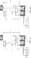
- FIGS. 1A - FIG. 1D depict an example of an optoelectronic module 100.
- the optoelectronic module 100 includes a transmission channel 102, a collection channel 104, a non-transitory computer-readable medium 106, and a processor 108.
- the transmission channel 102 is operable to generate intensity modulated light
- the collection channel 104 includes an array of demodulation pixels 110 operable to demodulate the intensity modulated light. Accordingly, distance data can be generated using the indirect time-of-flight technique.
- a first target 112 is depicted at a first distance 114, and a second target 116 is depicted at a second distance 118.
- Light 120 transmitted from the transmission channel 102 can be directed to the first target 112.
- Light 124A reflected from the first target 112 can be received in the collection channel 104 as depicted in FIG. 1A .
- light 120 transmitted from the transmission channel 102 can be directed to the second target 116.
- Reflected light 124B from the second target 116 can be received in the collection channel 104 as depicted, for example, in FIG. 1B .
- light 120 transmitted from the transmission channel 102 is directed to the first target 112 and to a cover glass 122 positioned between the optoelectronic module 100 and the first target 112 and the second target 116.
- the cover glass 122 is an example of a transmissive element.
- Light 124C reflected from the first target 112 can be received in the collection channel 104 and optical cross talk 126C, reflected from the cover glass 122, can be received in the collection channel 104, as depicted, for example, in FIG. 1C .
- light 120 transmitted from the transmission channel 102 can be directed to the second target 116 and to the cover glass 122 positioned between the optoelectronic module 100 and the first target 112 and the second target 116.
- Light 124D reflected from the second target 116 can be received in the collection channel 104 and optical cross talk 126D, reflected from the cover glass 122, can be received in the collection channel 104, as depicted, for example, in FIG. 1D .
- the first target 112 is reflective to the light 120 transmitted from the transmission channel 102.
- the first target 112 can be a white card.
- the second target 116 is absorptive to the light 120 transmitted from the transmission channel 102.
- the second target 116 can be a black card.
- the first target 112 is near the optoelectronic module 100 such that the first distance 114 is relatively small (e.g., 100 mm).
- the second target 116 is relatively far from the optoelectronic module 100 such that the distance 118 is relatively large (e.g., 400 mm).
- Both the first 114 and second 118 distances are dependent on characteristics of the optoelectronic module 100 (e.g., the optical power of the transmission channel and the intended operating range) and properties of the targets (e.g., degree of reflectivity and absorptance).
- the first target 112 and the first distance 114 are configured such that reflected light 124C is substantially greater than cross talk 126C (e.g., reflected light 124C is multiple orders of magnitude greater than cross talk 126C).
- the second target 116 and the second distance 116 are configured such that reflected light 124D is not substantially greater than cross talk 126D (e.g., reflected light 124D and cross talk 126D are within the same order of magnitude). In some instances, the cross talk 126C and the cross talk 126D are equal.
- the non-transitory computer-readable medium 106 includes machine-readbale instructions stored thereon that when executed on the processor 108, perform several operations.
- the operations can generate calibration data and distance data as illustrated, for example, in FIG. 2 and FIG. 3A - FIG. 3C .
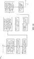
- FIG. 2 depicts an example of a method 200 for collecting calibration data with the optoelectronic module depicted in FIG. 1A - FIG. 1B not comprising all steps of the method of the invention.
- light 120 is transmitted from the transmission channel 102 to the first target 112 at the first distance 114.
- light 124A reflected from the first target 112 at the first distance 114 is received in the collection channel 104 as depicted in FIG. 1A .
- the received light is converted into a first signal A.
- the first signal A is saved to the non-transitory computer-readable medium 106 as a first vector A.
- light 120 is transmitted from the transmission channel 102 to the second target 116 at a second distance 118.
- reflected light 124B reflected form the second target 116 at the second distance 118 is received in the collection channel 104 as depicted in FIG. 1B .
- the received light is converted into a second signal B.
- the second signal B is saved to the non-transitory computer-readable medium 106 as a second vector B.
- FIG. 3A - 3C depict another example of a method 300 for collecting calibration data with the optoelectronic module depicted in FIG. 1A - FIG. 1D .
- light 120 is transmitted from the transmission channel 102 to the first target 112 at the first distance 114.
- light 124A reflected from the first target 112 at the first distance 114 is received in the collection channel 104 as depicted in FIG. 1A .
- the received light is converted into a first signal A.
- the first signal A is saved to the non-transitory computer-readable medium 106 as a first vector A.
- light 120 is transmitted from the transmission channel 102 to a second target 116 at a second distance 118.
- light 124B reflected form the second target 116 at the second distance 118 is received in the collection channel 104 as depicted, for example, in FIG. 1B .
- the received light is converted into a second signal B.
- the second signal B is saved to the non-transitory computer-readable medium 106 as a second vector B.
- the cover glass 122 is positioned between the transmission 102 and collection 104 channels and the first 112 and second targets 116 as depicted in FIG. 1C and FIG. 1D .
- the light 120 is transmitted from the transmission channel 102 to the cover glass 122 and the first target 112 at the first distance 114.
- light 124C reflected from the first target 112 and cross talk 126C reflected from the cover glass 122 are received in the collection channel 104 as depicted, for example, in FIG 1C .
- the received light is converted into a third signal C.
- the third signal C is saved to the non-transitory computer-readable medium as a third vector C.
- light 120 is transmitted from the transmission channel 102 to the cover glass 122 and the second target 116 at the second distance 118.
- light reflected from the second target 116 and light reflected from the cover glass 126D are received in the collection channel 102 as depicted, for example, in FIG. 1D .
- the received light is converted into a fourth signal D.
- the fourth signal D is saved to the non-transitory computer-readable medium 106 as a fourth vector D.
- the first vector A and the third vector C are recalled from the non-transitory computer-readable medium 106.
- FIG. 3B depicts further operations of method 300.
- an operation is performed on the first vector A and the third vector C.
- the scalar transmission factor T is saved to the non-transitory computer-readable medium 106.
- the second vector B and the scalar transmission factor T are recalled from the non-transitory computer-readable medium 106.
- an operation is performed on the second vector B and the scalar transmission factor T.
- the modified fourth vector is saved to the non-transitory computer-readable medium 106.
- the fourth vector D and the modified fourth vector M are recalled from the non-transitory computer-readable medium 106.
- an operation on the fourth vector D and the modified fourth vector M is performed.
- the cross-talk vector V is saved to the non-transitory computer-readable medium.
- the cross-talk vector V is used to calibrate the optoelectronic module 100 for subsequent measurements.
- FIG. 3C depict further operations of method 300.
- light 120 is transmitted from the transmission channel 102 to the cover glass 122 and an object at an object distance (not depicted).
- light reflected from the object at the object distance and light reflected from the cover glass are received in the collection channel 104.
- the received light is converted into an object signal.
- the object signal is saved to the non-transitory computer-readable medium 106 as an object vector O.
- the cross-talk vector V and the object vector O are recalled from the non-transitory computer-readable medium 106.
- an operation is performed on the cross-talk vector V and the object vector O.
- the cross-talk-corrected object vector Q is saved to the non-transitory computer-readable medium 106.
- the distance between the optoelectronic module and the object is determined from the phase of the cross-talk-corrected object vector Q.
- Embodiments of the subject matter described in this specification can be implemented as one or more computer program products, i.e., one or more modules of computer program instructions encoded on a computer readable medium for execution by, or to control the operation of, data processing apparatus.
- the computer readable medium can be a machine-readable storage device, a machine-readable storage substrate, a memory device, a composition of matter effecting a machine-readable propagated signal, or a combination of one or more of them.
- data processing apparatus and “computer” encompasses all apparatus, devices, and machines for processing data, including by way of example a programmable processor, a computer, or multiple processors or computers.
- the apparatus can include, in addition to hardware, code that creates an execution environment for the computer program in question, e.g., code that constitutes processor firmware, a protocol stack, a database management system, an operating system, or a combination of one or more of them.
- a computer program (also known as a program, software, software application, script, or code) can be written in any form of programming language, including compiled or interpreted languages, and it can be deployed in any form, including as a stand alone program or as a module, component, subroutine, or other unit suitable for use in a computing environment.
- a computer program does not necessarily correspond to a file in a file system.
- a program can be stored in a portion of a file that holds other programs or data (e.g., one or more scripts stored in a markup language document), in a single file dedicated to the program in question, or in multiple coordinated files (e.g., files that store one or more modules, sub programs, or portions of code).
- a computer program can be deployed to be executed on one computer or on multiple computers that are located at one site or distributed across multiple sites and interconnected by a communication network.
- the processes and logic flows described in this specification can be performed by one or more programmable processors executing one or more computer programs to perform functions by operating on input data and generating output.
- the processes and logic flows can also be performed by, and apparatus can also be implemented as, special purpose logic circuitry, e.g., an FPGA (field programmable gate array) or an ASIC (application specific integrated circuit).
- processors suitable for the execution of a computer program include, by way of example, both general and special purpose microprocessors, and any one or more processors of any kind of digital computer.
- a processor will receive instructions and data from a read only memory or a random access memory or both.
- the essential elements of a computer are a processor for performing instructions and one or more memory devices for storing instructions and data.
- a computer will also include, or be operatively coupled to receive data from or transfer data to, or both, one or more mass storage devices for storing data, e.g., magnetic, magneto optical disks, or optical disks.
- mass storage devices for storing data, e.g., magnetic, magneto optical disks, or optical disks.
- a computer need not have such devices.
- a computer can be embedded in another device, e.g., a mobile telephone, a personal digital assistant (PDA), a mobile audio player, a Global Positioning System (GPS) receiver, to name just a few.
- Computer readable media suitable for storing computer program instructions and data include all forms of non volatile memory, media and memory devices, including by way of example semiconductor memory devices, e.g., EPROM, EEPROM, and flash memory devices; magnetic disks, e.g., internal hard disks or removable disks; magneto optical disks; and CD ROM and DVD-ROM disks.
- the processor and the memory can be supplemented by, or incorporated in, special purpose logic circuitry.
- embodiments of the subject matter described in this specification can be implemented on a computer having a display device, e.g., a CRT (cathode ray tube) or LCD (liquid crystal display) monitor, for displaying information to the user and a keyboard and a pointing device, e.g., a mouse or a trackball, by which the user can provide input to the computer.
- a display device e.g., a CRT (cathode ray tube) or LCD (liquid crystal display) monitor
- keyboard and a pointing device e.g., a mouse or a trackball
- Other kinds of devices can be used to provide for interaction with a user as well; for example, feedback provided to the user can be any form of sensory feedback, e.g., visual feedback, auditory feedback, or tactile feedback; and input from the user can be received in any form, including acoustic, speech, or tactile input.
- aspects of the subject matter described in this specification can be implemented in a computing system that includes a back end component, e.g., as a data server, or that includes a middleware component, e.g., an application server, or that includes a front end component, e.g., a client computer having a graphical user interface or a Web browser through which a user can interact with an implementation of the subject matter described is this specification, or any combination of one or more such back end, middleware, or front end components.
- the components of the system can be interconnected by any form or medium of digital data communication, e.g., a communication network. Examples of communication networks include a local area network (“LAN”) and a wide area network (“WAN”), e.g., the Internet.
- LAN local area network
- WAN wide area network
- the computing system can include clients and servers.
- a client and server are generally remote from each other and typically interact through a communication network.
- the relationship of client and server arises by virtue of computer programs running on the respective computers and having a client-server relationship to each other.
Landscapes
- Engineering & Computer Science (AREA)
- Physics & Mathematics (AREA)
- General Physics & Mathematics (AREA)
- Radar, Positioning & Navigation (AREA)
- Remote Sensing (AREA)
- Computer Networks & Wireless Communication (AREA)
- Electromagnetism (AREA)
- Optical Radar Systems And Details Thereof (AREA)
- Length Measuring Devices By Optical Means (AREA)
- Measurement Of Optical Distance (AREA)
Description
- Optoelectronic modules, such as a proximity sensors and range imagining cameras, sometimes include at least one channel configured to transmit light to a target, and at least one channel configured to receive light reflected from the target. Further, optoelectronic modules sometimes include a transmissive element, such as an optical element, spectral filter, and/or cover glass placed between the channels and the target. In some cases, transmitted light may reflect from the transmissive element and may cause significant cross talk (e.g., light reflected from the transmissive element is collected by the channel configured to receive light).
- Cross talk can produce spurious signals in some cases. For example, an optoelectronic module operable to collect distance information or three-dimensional data via the indirect time-of-flight technique can be affected by spurious signals produced by cross talk emanating from a transmissive element. A signal generated from light reflected from a target and a transmissive element and received by an array of demodulation pixels within a collection channel sometimes includes a component resulting from the target and a component resulting from the transmissive element. Based on the indirect time-of-flight technique, the signal can be converted into a vector having a magnitude corresponding to the signal fidelity (including the transmissive properties of the transmissive element), and a phase ostensibly corresponding to the distance to the target. The phase, however, can be affected strongly by the cross-talk and, in the absence of sufficient calibration data, the corresponding distance data may be inaccurate.
- Methods for calibrating the cross talk due to the transmissive element of an optoelectronic module are known, but these methods sometimes require positioning a target at a very large distance (e.g., 10 - 30 meters or more) from the optoelectronic module. The long distances are often necessary to collect a pure cross talk signal. These methods can be impractical for a manufacturer or even an end user to implement.
- Accordingly, methods for calibrating and collecting distance data are needed that can be implemented within relatively short distances (e.g., less than a meter) such that a manufacturer or an end user of the optoelectronic module can perform the calibration measurements.
-
US 2011/0149071 Al describes a method and system to compensate for stray light errors in time of flight (TOF) camera systems uses reference targets in the in the field of view (FOV) that can be used to measure stray light. In different embodiments, one or more reference targets are used. -
AT 513402 Al - This disclosure describes optoelectronic modules, non-transitory computer-readable mediums, and methods for operating the same. In some instances, the modules are operable to provide cross talk calibration data using targets positioned within a relatively small distance from the optoelectronic modules (e.g., less than a meter). In some instances, the calibration data can be applied to measurements executed by optoelectronic modules to improve the accuracy of said measurements. In some instances, a non-transitory computer-readable medium for operating an optoelectronic module, comprising instructions stored thereon, can, when executed on a processor, perform operations to provide cross talk calibration data, and provide measurements with improved accuracy.
- A first aspect describes a method for operating an optoelectronic module. The optoelectronic module includes a transmission channel and a collection channel. The optoelectronic module is operable to transmit light from the transmission channel and to receive light in the collection channel. The method includes: transmitting light from the transmission channel to a first target at a first distance; receiving light in the collection channel reflected from the first target at the first distance; converting the received light into a first signal A; saving the first signal A to a non-transitory computer-readable medium as a first vector A; transmitting light from the transmission channel to a second target at a second distance; receiving light in the collection channel reflected from the second target at the second distance; converting the received light into a second signal B; and saving the second signal B to the non-transitory computer-readable medium as a second vector B.
- The method includes positioning a transmissive element between a transmission channel and a collection channel and a first target and a second target; transmitting light from the transmission channel to the transmissive element and the first target at the first distance; receiving in the collection channel light reflected from the first target and light reflected from the transmissive element; converting the received light into a third signal C; saving the third signal C to a non-transitory computer-readable medium as a third vector C; transmitting light from the transmission channel to the transmissive element and the second target at the second distance; receiving in the collection channel light reflected from the second target and light reflected from the transmissive element; converting the received light into a fourth signal D; saving the fourth signal D to the non-transitory computer-readable medium as a fourth vector D; recalling (e.g., retrieving) a first vector A and the third vector C from the non-transitory computer-readable medium; performing an operation on the first vector A and the third vector C, the operation including dividing the magnitude of the third vector C by the magnitude of the first vector A, and equating a scalar transmission factor T to the square root of the quotient; saving the scalar transmission factor T to the non-transitory computer-readable medium; recalling the second vector B and the scalar transmission factor T from the non-transitory computer-readable medium; performing an operation on the second vector B and the scalar transmission factor T, the operation including multiplying the second vector B by the square of the scalar transmission factor T, and equating a modified fourth vector M to the product; saving the modified fourth vector to the non-transitory computer-readable medium; recalling the fourth vector D and the modified fourth vector M from the non-transitory computer-readable medium; performing an operation on the fourth vector D and the modified fourth vector M, the operation including subtracting the modified fourth vector M from the fourth vector D, equating a cross-talk vector V to the difference; and saving the cross-talk vector V to the non-transitory computer-readable medium, and using the cross-talk vector V to calibrate the optoelectronic module for subsequent measurements.
- In a further aspect, for example, the method for operating an optoelectronic module includes determining a cross-talk-corrected object vector Q. The method includes transmitting light from the transmission channel to the transmissive element and an object at an object distance; receiving light in the collection channel light reflected from the object at the object distance and light reflected from the transmissive element; converting the received light into an object signal; saving the object signal to the non-transitory computer-readable medium as an object vector O; recalling the cross-talk vector V and the object vector O from the non-transitory computer-readable medium; and performing an operation on the cross-talk vector V and the object vector O, the operation including subtracting the cross-talk vector V from the object vector O, the difference being the cross-talk corrected object vector Q.
- Some implementations include one or more of the following features. For example, the method for operating an optoelectronic module can include saving the cross-talk-corrected object vector Q to the non-transitory computer-readable medium.
- In some instances, the method for operating an optoelectronic module includes determining a distance between the optoelectronic module and the object from a phase of the cross-talk-corrected object vector Q.
- In some instances, the method for operating an optoelectronic module includes the first target that is reflective to the light transmitting from the transmission channel.
- In some instances, the method for operating an optoelectronic module includes the second target that is absorptive to the light transmitting from the transmission channel.
- In some instances, the method for operating an optoelectronic module includes the second distance that is greater than the first distance.
- In a further aspect, for example, the method for operating an optoelectronic module includes light transmitted by the transmission channel that is intensity modulated, and the collection channel includes an array of demodulation pixels operable to demodulate intensity modulated light received by the collection channel.
- In another aspect, a non-transitory computer-readable medium includes machine-readable instructions stored thereon. When the instructions are executed by a processor of an optoelectronic module comprising a transmission channel and a collection channel, operations are performed including: transmitting light from the transmission channel to a first target at a first distance; receiving light in the collection channel reflected from the first target at the first distance; converting the received light into a first signal A; saving the first signal A to the non-transitory computer-readable medium as a first vector A; transmitting light from the transmission channel to a second target at a second distance; receiving light in the collection channel reflected from the second target at the second distance; converting the received light into a second signal B; and saving the second signal B to the non-transitory computer-readable medium as a second vector B.
- The operations include: transmitting light from the transmission channel to a transmissive element positioned between the transmission channel and the collection channel and the first target and the second target; transmitting light from the transmission channel to the first target at a first distance; receiving in the collection channel light reflected from the first target and light reflected from the transmissive element; converting the received light into a third signal C; and saving the third signal C to the non-transitory computer-readable medium as a third vector C.
- The operations include: transmitting light from the transmission channel to the transmissive element and the second target at a second distance; receiving in the collection channel light reflected from the second target and light reflected from the transmissive element; converting the received light into a fourth signal D; and saving the fourth signal D to the non-transitory computer-readable medium as a fourth vector D.
- The operations include: recalling the first vector A and the third vector C from the non-transitory computer-readable medium; performing an operation on the first vector A and the third vector C, the operation including dividing the magnitude of the third vector C by the magnitude of the first vector A, and equating a scalar transmission factor T to the square root of the quotient; and saving the scalar transmission factor T to the non-transitory computer-readable medium.
- The operations include: recalling the second vector B and the scalar transmission factor T from the non-transitory computer-readable medium; performing an operation on the second vector B and the scalar transmission factor T, the operation including multiplying the second vector B by the square of the scalar transmission factor T, and equating a modified fourth vector M to the product; saving the modified fourth vector to the non-transitory computer-readable medium; recalling the fourth vector D and the modified fourth vector M from the non-transitory computer-readable medium; performing an operation on the fourth vector D and the modified fourth vector M, the operation including subtracting the modified fourth vector M from the fourth vector D, and equating a cross-talk vector V to the difference; saving the cross-talk vector V to the non-transitory computer-readable medium, and using the cross-talk vector V to calibrate the optoelectronic module for subsequent measurements.
- In further aspect, for example, the operations further include: transmitting light from the transmission channel to the transmissive element and an object at an object distance; receiving light in the collection channel light reflected from the object at the object distance and light reflected from the transmissive element; converting the received light into an object signal; saving the object signal to the non-transitory computer-readable medium as an object vector O; recalling the cross-talk vector V and the object vector O from the non-transitory computer-readable medium; and performing an operation on the cross-talk vector V and the object vector O, the operation including subtracting the cross-talk vector V from the object vector O, the difference being a cross-talk corrected object vector Q.
- In a further aspect, for example, the operations further include: saving the cross-talk-corrected object vector Q to the non-transitory computer-readable medium; and determining a distance between the optoelectronic module and the object from the phase of the cross-talk-corrected object vector Q.
- In another aspect, an optoelectronic module includes a transmission channel, a collection channel, a non-transitory computer-readable medium, and a processor. The transmission channel includes a light-emitting component operable to generate intensity modulated light. The collection channel includes an array of demodulation pixels operable to demodulate the intensity modulated light. The non-transitory computer-readable medium includes instructions stored thereon. When the instructions are executed on the processor, operations are performed including: transmitting light from the transmission channel to a first target at a first distance; receiving light in the collection channel reflected from the first target at the first distance; converting the received light into a first signal A; saving the first signal A to the non-transitory computer-readable medium as a first vector A; transmitting light from the transmission channel to a second target at a second distance; receiving light in the collection channel reflected from the second target at the second distance; converting the received light into a second signal B; saving the second signal B to the non-transitory computer-readable medium as a second vector B; transmitting light from the transmission channel to a transmissive element positioned between the transmission and collection channels and the first and second targets; transmitting light from the transmission channel to the first target at the first distance; receiving in the collection channel light reflected from the first target and light reflected from the transmissive element; converting the received light into a third signal C; saving the third signal C to the non-transitory computer-readable medium as a third vector C; transmitting light from the transmission channel to the transmissive element and the second target at the second distance; receiving in the collection channel light reflected from the second target and light reflected from the transmissive element; converting the received light into a fourth signal D; saving the fourth signal D to the non-transitory computer-readable medium as a fourth vector D; recalling the first vector A and the third vector C from the non-transitory computer-readable medium; performing an operation on the first vector A and the third vector C, the operation including dividing the magnitude of the third vector C by the magnitude of the first vector A, and equating the scalar transmission factor T to the square root of the quotient; saving the scalar transmission factor T to the non-transitory computer-readable medium; recalling the second vector B and the scalar transmission factor T from the non-transitory computer-readable medium; performing an operation on the second vector B and the scalar transmission factor, the operation including multiplying the second vector B by the square of the scalar transmission factor T, and equating the modified fourth vector M to the product; saving the modified fourth vector to the non-transitory computer-readable medium; recalling the fourth vector D and the modified fourth vector M from the non-transitory computer-readable medium; performing an operation on the fourth vector D and the modified fourth vector M, the operation including subtracting the modified fourth vector M from the fourth vector D, and equating the cross-talk vector V to the difference; saving the cross-talk vector V to the non-transitory computer-readable medium; using the cross-talk vector V to calibrate the optoelectronic module for subsequent measurements. Moreover, the processor is operable to execute the instructions stored on the non-transitory computer-readable medium.
- Other aspects, features, and advantages will be apparent from the following detailed description, the accompanying drawings, and the claims
-
-
FIG. 1A depicts an example of an optoelectronic module with a first target at a first distance. -
FIG. 1B depicts an example of an optoelectronic module with a second target at a second distance. -
FIG. 1C depicts an example of an optoelectronic module with a first target at a first distance and a cover glass positioned between the example optoelectronic module and the first target. -
FIG. 1D depicts an example of an optoelectronic module with a second target at a second distance and a cover glass positioned between the example optoelectronic module and the second target. -
FIG. 2 depicts an example of a method for collecting calibration data. -
FIG. 3A - 3C depict another example of a method for collecting calibration data. -
FIGS. 1A - FIG. 1D depict an example of anoptoelectronic module 100. Theoptoelectronic module 100 includes atransmission channel 102, acollection channel 104, a non-transitory computer-readable medium 106, and aprocessor 108. Thetransmission channel 102 is operable to generate intensity modulated light, and thecollection channel 104 includes an array ofdemodulation pixels 110 operable to demodulate the intensity modulated light. Accordingly, distance data can be generated using the indirect time-of-flight technique. - A
first target 112 is depicted at afirst distance 114, and asecond target 116 is depicted at asecond distance 118.Light 120 transmitted from thetransmission channel 102 can be directed to thefirst target 112.Light 124A reflected from thefirst target 112 can be received in thecollection channel 104 as depicted inFIG. 1A . Similarly, light 120 transmitted from thetransmission channel 102 can be directed to thesecond target 116. Reflected light 124B from thesecond target 116 can be received in thecollection channel 104 as depicted, for example, inFIG. 1B . - In some instances, light 120 transmitted from the
transmission channel 102 is directed to thefirst target 112 and to acover glass 122 positioned between theoptoelectronic module 100 and thefirst target 112 and thesecond target 116. Thecover glass 122 is an example of a transmissive element.Light 124C reflected from thefirst target 112 can be received in thecollection channel 104 andoptical cross talk 126C, reflected from thecover glass 122, can be received in thecollection channel 104, as depicted, for example, inFIG. 1C . - In some instances, light 120 transmitted from the
transmission channel 102 can be directed to thesecond target 116 and to thecover glass 122 positioned between theoptoelectronic module 100 and thefirst target 112 and thesecond target 116.Light 124D reflected from thesecond target 116 can be received in thecollection channel 104 andoptical cross talk 126D, reflected from thecover glass 122, can be received in thecollection channel 104, as depicted, for example, inFIG. 1D . - In some instance, the
first target 112 is reflective to the light 120 transmitted from thetransmission channel 102. For example, thefirst target 112 can be a white card. In some instances, thesecond target 116 is absorptive to the light 120 transmitted from thetransmission channel 102. For example, thesecond target 116 can be a black card. In some instances, thefirst target 112 is near theoptoelectronic module 100 such that thefirst distance 114 is relatively small (e.g., 100 mm). In some instances, thesecond target 116 is relatively far from theoptoelectronic module 100 such that thedistance 118 is relatively large (e.g., 400 mm). Both the first 114 and second 118 distances are dependent on characteristics of the optoelectronic module 100 (e.g., the optical power of the transmission channel and the intended operating range) and properties of the targets (e.g., degree of reflectivity and absorptance). Thefirst target 112 and thefirst distance 114 are configured such that reflected light 124C is substantially greater thancross talk 126C (e.g., reflected light 124C is multiple orders of magnitude greater thancross talk 126C). Thesecond target 116 and thesecond distance 116 are configured such that reflected light 124D is not substantially greater thancross talk 126D (e.g., reflected light 124D and crosstalk 126D are within the same order of magnitude). In some instances, thecross talk 126C and thecross talk 126D are equal. - The non-transitory computer-
readable medium 106 includes machine-readbale instructions stored thereon that when executed on theprocessor 108, perform several operations. The operations can generate calibration data and distance data as illustrated, for example, inFIG. 2 andFIG. 3A - FIG. 3C . -
FIG. 2 depicts an example of amethod 200 for collecting calibration data with the optoelectronic module depicted inFIG. 1A - FIG. 1B not comprising all steps of the method of the invention. At 202, light 120 is transmitted from thetransmission channel 102 to thefirst target 112 at thefirst distance 114. At 204, light 124A reflected from thefirst target 112 at thefirst distance 114 is received in thecollection channel 104 as depicted inFIG. 1A . At 206, the received light is converted into a first signal A. At 208, the first signal A is saved to the non-transitory computer-readable medium 106 as a first vector A. - At 210, light 120 is transmitted from the
transmission channel 102 to thesecond target 116 at asecond distance 118. At 212, reflected light 124B reflected form thesecond target 116 at thesecond distance 118 is received in thecollection channel 104 as depicted inFIG. 1B . At 214, the received light is converted into a second signal B. At 216, the second signal B is saved to the non-transitory computer-readable medium 106 as a second vector B. -
FIG. 3A - 3C depict another example of amethod 300 for collecting calibration data with the optoelectronic module depicted inFIG. 1A - FIG. 1D . At 302, light 120 is transmitted from thetransmission channel 102 to thefirst target 112 at thefirst distance 114. At 304, light 124A reflected from thefirst target 112 at thefirst distance 114 is received in thecollection channel 104 as depicted inFIG. 1A . At 306, the received light is converted into a first signal A. At 308, the first signal A is saved to the non-transitory computer-readable medium 106 as a first vector A. - At 310, light 120 is transmitted from the
transmission channel 102 to asecond target 116 at asecond distance 118. At 312, light 124B reflected form thesecond target 116 at thesecond distance 118 is received in thecollection channel 104 as depicted, for example, inFIG. 1B . At 314, the received light is converted into a second signal B. At 316, the second signal B is saved to the non-transitory computer-readable medium 106 as a second vector B. - At 318, the
cover glass 122 is positioned between thetransmission 102 andcollection 104 channels and the first 112 andsecond targets 116 as depicted inFIG. 1C and FIG. 1D . At 320, the light 120 is transmitted from thetransmission channel 102 to thecover glass 122 and thefirst target 112 at thefirst distance 114. At 322, light 124C reflected from thefirst target 112 andcross talk 126C reflected from thecover glass 122 are received in thecollection channel 104 as depicted, for example, inFIG 1C . At 324, the received light is converted into a third signal C. - At 326, the third signal C is saved to the non-transitory computer-readable medium as a third vector C. At 328, light 120 is transmitted from the
transmission channel 102 to thecover glass 122 and thesecond target 116 at thesecond distance 118. At 330, light reflected from thesecond target 116 and light reflected from thecover glass 126D are received in thecollection channel 102 as depicted, for example, inFIG. 1D . - At 332, the received light is converted into a fourth signal D. At 334, the fourth signal D is saved to the non-transitory computer-
readable medium 106 as a fourth vector D. At 336, the first vector A and the third vector C are recalled from the non-transitory computer-readable medium 106. -
FIG. 3B depicts further operations ofmethod 300. At 338, an operation is performed on the first vector A and the third vector C. The operation includes dividing the magnitude of the third vector C by the magnitude of the first vector A, and equating a scalar transmission factor T to the square root of the quotient; for example:
- At 340, the scalar transmission factor T is saved to the non-transitory computer-
readable medium 106. - At 342, the second vector B and the scalar transmission factor T are recalled from the non-transitory computer-
readable medium 106. At 344, an operation is performed on the second vector B and the scalar transmission factor T. The operation includes multiplying the second vector B by the square of the scalar transmission factor T, and equating a modified fourth vector M to the product; for example:
- At 346, the modified fourth vector is saved to the non-transitory computer-
readable medium 106. - At 348, the fourth vector D and the modified fourth vector M are recalled from the non-transitory computer-
readable medium 106. At 350, an operation on the fourth vector D and the modified fourth vector M is performed. The operation includes subtracting the modified fourth vector M from the fourth vector D, and equating a cross-talk vector V to the difference; for example:
- At 352, the cross-talk vector V is saved to the non-transitory computer-readable medium.
- The cross-talk vector V is used to calibrate the
optoelectronic module 100 for subsequent measurements. -
FIG. 3C depict further operations ofmethod 300. At 354, light 120 is transmitted from thetransmission channel 102 to thecover glass 122 and an object at an object distance (not depicted). At 356, light reflected from the object at the object distance and light reflected from the cover glass are received in thecollection channel 104. At 358, the received light is converted into an object signal. At 360, the object signal is saved to the non-transitory computer-readable medium 106 as an object vector O. - At 362, the cross-talk vector V and the object vector O are recalled from the non-transitory computer-
readable medium 106. At 364, an operation is performed on the cross-talk vector V and the object vector O. The operation includes subtracting the cross-talk vector V from the object vector O, the difference being the cross-talk corrected object vector Q; for example:
- At 366, the cross-talk-corrected object vector Q is saved to the non-transitory computer-
readable medium 106. At 368, the distance between the optoelectronic module and the object is determined from the phase of the cross-talk-corrected object vector Q. - Various aspects of the subject matter and the functional operations described in this specification can be implemented in digital electronic circuitry, or in computer software, firmware, or hardware, including the structures disclosed in this specification and their structural equivalents, or in combinations of one or more of them. Embodiments of the subject matter described in this specification can be implemented as one or more computer program products, i.e., one or more modules of computer program instructions encoded on a computer readable medium for execution by, or to control the operation of, data processing apparatus. The computer readable medium can be a machine-readable storage device, a machine-readable storage substrate, a memory device, a composition of matter effecting a machine-readable propagated signal, or a combination of one or more of them. The terms "data processing apparatus" and "computer" encompasses all apparatus, devices, and machines for processing data, including by way of example a programmable processor, a computer, or multiple processors or computers. The apparatus can include, in addition to hardware, code that creates an execution environment for the computer program in question, e.g., code that constitutes processor firmware, a protocol stack, a database management system, an operating system, or a combination of one or more of them.
- A computer program (also known as a program, software, software application, script, or code) can be written in any form of programming language, including compiled or interpreted languages, and it can be deployed in any form, including as a stand alone program or as a module, component, subroutine, or other unit suitable for use in a computing environment. A computer program does not necessarily correspond to a file in a file system. A program can be stored in a portion of a file that holds other programs or data (e.g., one or more scripts stored in a markup language document), in a single file dedicated to the program in question, or in multiple coordinated files (e.g., files that store one or more modules, sub programs, or portions of code). A computer program can be deployed to be executed on one computer or on multiple computers that are located at one site or distributed across multiple sites and interconnected by a communication network.
- The processes and logic flows described in this specification can be performed by one or more programmable processors executing one or more computer programs to perform functions by operating on input data and generating output. The processes and logic flows can also be performed by, and apparatus can also be implemented as, special purpose logic circuitry, e.g., an FPGA (field programmable gate array) or an ASIC (application specific integrated circuit).
- Processors suitable for the execution of a computer program include, by way of example, both general and special purpose microprocessors, and any one or more processors of any kind of digital computer. Generally, a processor will receive instructions and data from a read only memory or a random access memory or both. The essential elements of a computer are a processor for performing instructions and one or more memory devices for storing instructions and data. Generally, a computer will also include, or be operatively coupled to receive data from or transfer data to, or both, one or more mass storage devices for storing data, e.g., magnetic, magneto optical disks, or optical disks. However, a computer need not have such devices. Moreover, a computer can be embedded in another device, e.g., a mobile telephone, a personal digital assistant (PDA), a mobile audio player, a Global Positioning System (GPS) receiver, to name just a few. Computer readable media suitable for storing computer program instructions and data include all forms of non volatile memory, media and memory devices, including by way of example semiconductor memory devices, e.g., EPROM, EEPROM, and flash memory devices; magnetic disks, e.g., internal hard disks or removable disks; magneto optical disks; and CD ROM and DVD-ROM disks. The processor and the memory can be supplemented by, or incorporated in, special purpose logic circuitry.
- To provide for interaction with a user, embodiments of the subject matter described in this specification can be implemented on a computer having a display device, e.g., a CRT (cathode ray tube) or LCD (liquid crystal display) monitor, for displaying information to the user and a keyboard and a pointing device, e.g., a mouse or a trackball, by which the user can provide input to the computer. Other kinds of devices can be used to provide for interaction with a user as well; for example, feedback provided to the user can be any form of sensory feedback, e.g., visual feedback, auditory feedback, or tactile feedback; and input from the user can be received in any form, including acoustic, speech, or tactile input.
- Aspects of the subject matter described in this specification can be implemented in a computing system that includes a back end component, e.g., as a data server, or that includes a middleware component, e.g., an application server, or that includes a front end component, e.g., a client computer having a graphical user interface or a Web browser through which a user can interact with an implementation of the subject matter described is this specification, or any combination of one or more such back end, middleware, or front end components. The components of the system can be interconnected by any form or medium of digital data communication, e.g., a communication network. Examples of communication networks include a local area network ("LAN") and a wide area network ("WAN"), e.g., the Internet.
- The computing system can include clients and servers. A client and server are generally remote from each other and typically interact through a communication network. The relationship of client and server arises by virtue of computer programs running on the respective computers and having a client-server relationship to each other.
- Various modifications may be made to the foregoing implementations, and features described above in different implementations may be combined in the same implementation. Further, unless expressly stated or implicitly required, the various operations may be performed in a different order than set forth in the foregoing examples. Some implementations may omit some operations and/or may include additional operations.
Claims (10)
- A method (200, 300) for operating an optoelectronic module (100) having a transmission channel (102), a collection channel (104), and being operable to transmit light from the transmission channel (102) and to receive light in the collection channel (104), the method comprising:transmitting (202, 302) light (120) from the transmission channel (102) to a first target (112) at a first distance (114);receiving (204, 304) light (124) in the collection channel (104) reflected from the first target (112) at the first distance (114);converting (206, 306) the received light into a first signal A;saving (208, 308) the first signal A to a non-transitory computer-readable medium (106) as a first vector A;transmitting (210, 310) light from the transmission channel (102) to a second target (116) at a second distance (118);receiving (212, 312) light (124B) in the collection channel (104) reflected from the second target (116) at the second distance (118);converting (214, 314) the received light into a second signal B; andsaving (216, 316) the second signal B to the non-transitory computer-readable medium (106) as a second vector B.positioning (318) a transmissive element (122) between the transmission and collection channels (102, 104) and the first and second targets (112, 116);transmitting (320) light from the transmission channel (102) to the transmissive element (122) and the first target (112) at the first distance (114);receiving (322) in the collection channel (104) light reflected from the first target (112) and light reflected from the transmissive element (122);converting (324) the received light into a third signal C;saving (326) the third signal C to the non-transitory computer-readable medium (108) as a third vector C;transmitting (328) light from the transmission channel (104) to the transmissive element (122) and the second target (116) at the second distance (118);receiving (330) in the collection channel (104) light reflected from the second target (116) and light reflected from the transmissive element (122);converting (332) the received light into a fourth signal D;saving (334) the fourth signal D to the non-transitory computer-readable medium (108) as a fourth vector D;recalling (336) the first vector A and the third vector C from the non-transitory computer-readable medium (108);performing (338) an operation on the first vector A and the third vector C, the operation including dividing the magnitude of the third vector C by the magnitude of the first vector A, and equating a scalar transmission factor T to the square root of the quotient;saving (340) the scalar transmission factor T to the non-transitory computer-readable medium (108);recalling (342) the second vector B and the scalar transmission factor T from the non-transitory computer-readable medium (108);performing (344) an operation on the second vector B and the scalar transmission factor T, the operation including multiplying the second vector B by the square of the scalar transmission factor T, and equating a modified fourth vector M to the product;saving (346) the modified fourth vector to the non-transitory computer-readable medium (108);recalling (348) the fourth vector D and the modified fourth vector M from the non-transitory computer-readable medium (108);performing (350) an operation on the fourth vector D and the modified fourth vector M, the operation including subtracting the modified fourth vector M from the fourth vector D, and equating a cross-talk vector V to the difference;saving (352) the cross-talk vector V to the non-transitory computer-readable medium (108); andusing the cross-talk vector V to calibrate the optoelectronic module (100) for subsequent measurements.
- The method (200, 300) of claim 1 further comprising determining a cross-talk-corrected object vector Q, the method comprising:transmitting (354) light from the transmission channel (102) to the transmissive element (122) and an object at an object distance;receiving (356) light in the collection channel (104) light reflected from the object at the object distance and light reflected from the transmissive element (122);converting (358) the received light into an object signal;saving (360) the object signal to a non-transitory computer-readable medium (108) as an object vector O;recalling (362) the cross-talk vector V and the object vector O from the non-transitory computer-readable medium (108); andperforming (364) an operation on the cross-talk vector V and the object vector O, the operation including subtracting the cross-talk vector V from the object vector O, the difference being the cross-talk corrected object vector Q.
- The method (200, 300) of claim 2, further comprising saving (366) the cross-talk-corrected object vector Q to a non-transitory computer-readable medium (106), and optionally wherein the method (200, 300) further comprises determining (368) the distance between the optoelectronic module (100) and the object from the phase of the cross-talk-corrected object vector Q.
- The method (200, 300) of claim 1, wherein either a) the first target is reflective to the light transmitting from the transmission channel (102) or b) the second target is absorptive to the light transmitting from the transmission channel (102).
- The method (200, 300) of claim 1, wherein the second distance is greater than the first distance.
- The method (200, 300) of any one of claims 1 and 2, wherein the light transmitted by the transmission channel (102) is intensity modulated, and the collection channel (104) includes an array of demodulation pixels (110) operable to demodulate intensity modulated light received by the collection channel (102).
- A non-transitory computer-readable medium (106) comprising machine-readable instructions stored thereon, that when executed on a processor (108) of an optoelectronic module comprising a transmission channel (102) and a collection channel (104), perform operations including:transmitting (202) light from the transmission channel (102) to a first target (114) at a first distance (114);receiving (204) light in the collection channel (104) reflected from the first target (114) at the first distance (114);converting (206) the received light into a first signal A;saving (208) the first signal A to the non-transitory computer-readable medium (106) as a first vector A;transmitting (210) light from the transmission channel (102) to a second target (116) at a second distance (118);receiving (212) light in the collection channel (104) reflected from the second target (116) at the second distance (118);converting (214) the received light into a second signal B; andsaving (216) the second signal B to the non-transitory computer-readable medium (106) as a second vector B;transmitting light from the transmission channel (102) to a transmissive element (122) positioned between the transmission and collection channels (102, 104) and the first and second targets (112, 116);transmitting light from the transmission channel (102) to the first target (112) at the first distance (114);receiving in the collection channel (104) light reflected from the first target (112) and light reflected from the transmissive element (122);converting the received light into a third signal C; andsaving the third signal C to the non-transitory computer-readable medium (106) as a third vector C;transmitting light from the transmission channel (102) to the transmissive element (122) and the second target (116) at the second distance (118);receiving in the collection channel (104) light reflected from the second target (118) and light reflected from the transmissive element (122);converting the received light into a fourth signal D; andsaving the fourth signal D to the non-transitory computer-readable medium (106) as a fourth vector D;recalling the first vector A and the third vector C from the non-transitory computer-readable medium (106);performing an operation on the first vector A and the third vector C, the operation including dividing the magnitude of the third vector C by the magnitude of the first vector A, and equating the scalar transmission factor T to the square root of the quotient; andsaving the scalar transmission factor T to the non-transitory computer-readable medium (106);recalling the second vector B and the scalar transmission factor T from the non-transitory computer-readable medium (106);performing an operation on the second vector B and the scalar transmission factor T, the operation including multiplying the second vector B by the square of the scalar transmission factor T, and equating the modified fourth vector M to the product;saving the modified fourth vector to the non-transitory computer-readable medium (106);recalling the fourth vector D and the modified fourth vector M from the non-transitory computer-readable medium (106);performing an operation on the fourth vector D and the modified fourth vector M, the operation including subtracting the modified fourth vector M from the fourth vector D, and equating the cross-talk vector V to the difference;saving the cross-talk vector V to the non-transitory computer-readable medium (106); andusing the cross-talk vector V to calibrate the optolectronic module (100) for subsequent measurements.
- The non-transitory computer-readable medium (106) of claim 7, comprising machine-readable instructions stored thereon, that when executed on a processor (108), perform operations including:transmitting light from the transmission channel (102) to the transmissive element (122) and an object at an object distance;receiving light in the collection channel (104) light reflected from the object at the object distance and light reflected from the transmissive element (122);converting the received light into an object signal;saving the object signal to the non-transitory computer-readable medium (106) as an object vector O;recalling the cross-talk vector V and the object vector O from the non-transitory computer-readable medium (106); andperforming an operation on the cross-talk vector V and the object vector O, the operation including subtracting the cross-talk vector V from the object vector O, the difference being across-talk corrected object vector Q.
- The non-transitory computer-readable medium (106) of claim 8, comprising machine-readable instructions stored thereon, that when executed on a processor (108), perform operations including:saving the cross-talk-corrected object vector Q to a non-transitory computer-readable medium (106); anddetermining the distance between the optoelectronic module and the object from the phase of the cross-talk-corrected object vector Q.
- An optoelectronic module (100) comprising:a transmission channel (102), a collection channel (104), a non-transitory computer-readable medium (106), and a processor (108);the transmission channel (102) including a light-emitting component operable to generate intensity modulated light;the collection channel (104) including an array of demodulation pixels (110) operable to demodulate the intensity modulated light; the non-transitory computer-readable medium (106) according to any one of claims 7-9wherein the processor (108) is operable to execute the instructions stored on the non-transitory computer-readable medium (106).
Applications Claiming Priority (2)
| Application Number | Priority Date | Filing Date | Title |
|---|---|---|---|
| US201662288575P | 2016-01-29 | 2016-01-29 | |
| PCT/SG2017/050041 WO2017131586A1 (en) | 2016-01-29 | 2017-01-27 | Optoelectronic modules and methods for operating the same |
Publications (3)
| Publication Number | Publication Date |
|---|---|
| EP3408611A1 EP3408611A1 (en) | 2018-12-05 |
| EP3408611A4 EP3408611A4 (en) | 2019-02-27 |
| EP3408611B1 true EP3408611B1 (en) | 2022-08-24 |
Family
ID=59398489
Family Applications (1)
| Application Number | Title | Priority Date | Filing Date |
|---|---|---|---|
| EP17744656.4A Active EP3408611B1 (en) | 2016-01-29 | 2017-01-27 | Optoelectronic modules and methods for operating the same |
Country Status (5)
| Country | Link |
|---|---|
| US (1) | US10746544B2 (en) |
| EP (1) | EP3408611B1 (en) |
| CN (1) | CN108885100B (en) |
| TW (1) | TWI713688B (en) |
| WO (1) | WO2017131586A1 (en) |
Family Cites Families (17)
| Publication number | Priority date | Publication date | Assignee | Title |
|---|---|---|---|---|
| US6023322A (en) * | 1995-05-04 | 2000-02-08 | Bushnell Corporation | Laser range finder with target quality display and scan mode |
| WO2009155198A1 (en) * | 2008-06-18 | 2009-12-23 | Ev Products, Inc. | Count correction in a photon counting imaging system |
| US8502153B2 (en) | 2009-11-20 | 2013-08-06 | Avago Technologies General Ip (Singapore) Pte. Ltd. | Methods, systems and devices for crosstalk measurement and cancellation in optical proximity sensors |
| AU2010339731B2 (en) * | 2009-12-21 | 2016-01-28 | Heptagon Micro Optics Pte. Ltd. | Stray light compensation method and system for time of flight camera systems |
| US8964028B2 (en) * | 2009-12-21 | 2015-02-24 | Mesa Imaging Ag | Stray light compensation method and system for time of flight camera systems |
| TWI448666B (en) * | 2010-06-15 | 2014-08-11 | Pixart Imaging Inc | Calibrating method of calibrating measured distance of measured object measured by distance-measuring device according to ambient temperature and device thereof |
| US8988660B2 (en) | 2011-06-29 | 2015-03-24 | Silicon Laboratories Inc. | Optical detector |
| CN103363951B (en) * | 2012-04-10 | 2015-11-25 | 通用电气公司 | Trigonometry distance measurement system and method |
| EP2662702A1 (en) * | 2012-05-07 | 2013-11-13 | Leica Geosystems AG | Laser tracker with interferometer and absolute distance measuring unit and calibration method for a laser tracker |
| DE102012208308A1 (en) * | 2012-05-18 | 2013-11-21 | Robert Bosch Gmbh | Optical rangefinder with calibration device to account for crosstalk |
| AT513402B1 (en) | 2012-10-05 | 2014-09-15 | Riegl Laser Measurement Sys | Method for distance measurement |
| TWI512313B (en) | 2012-11-09 | 2015-12-11 | Upi Semiconductor Corp | Proximity sensor and operating method thereof |
| CN103884315A (en) * | 2012-12-21 | 2014-06-25 | 宗经投资股份有限公司 | Ranging method and computer program product |
| TWI498789B (en) | 2013-05-20 | 2015-09-01 | Lite On Singapore Pte Ltd | Proximity sensing method, proximity sensing device, and electronic device |
| US9279726B2 (en) | 2013-08-06 | 2016-03-08 | Avago Technologies General Ip (Singapore) Pte. Ltd. | Optical device with reduced crosstalk |
| US9250714B2 (en) | 2013-11-27 | 2016-02-02 | Intersil Americas LLC | Optical proximity detectors |
| WO2015136099A2 (en) | 2014-03-14 | 2015-09-17 | Mesa Imaging Ag | Optical imaging modules and optical detection modules including a time-of-flight sensor |
-
2017
- 2017-01-27 EP EP17744656.4A patent/EP3408611B1/en active Active
- 2017-01-27 US US16/073,168 patent/US10746544B2/en active Active
- 2017-01-27 WO PCT/SG2017/050041 patent/WO2017131586A1/en not_active Ceased
- 2017-01-27 CN CN201780018936.9A patent/CN108885100B/en active Active
- 2017-02-02 TW TW106103551A patent/TWI713688B/en active
Also Published As
| Publication number | Publication date |
|---|---|
| CN108885100B (en) | 2021-06-01 |
| CN108885100A (en) | 2018-11-23 |
| EP3408611A4 (en) | 2019-02-27 |
| US20190033071A1 (en) | 2019-01-31 |
| EP3408611A1 (en) | 2018-12-05 |
| US10746544B2 (en) | 2020-08-18 |
| TWI713688B (en) | 2020-12-21 |
| WO2017131586A1 (en) | 2017-08-03 |
| TW201733288A (en) | 2017-09-16 |
Similar Documents
| Publication | Publication Date | Title |
|---|---|---|
| EP3561539B1 (en) | Angular resolution of targets using separate radar receivers | |
| JP2022130554A (en) | Method and system for pitch-catch scanning of coherent lidar | |
| US10003757B2 (en) | Method and apparatus for de-noising data from a distance sensing camera | |
| US9903941B2 (en) | Time of flight camera device and method of driving the same | |
| US12174324B2 (en) | In-situ sensor calibration for autonomous vehicles | |
| CN106154279A (en) | A kind of laser range finder bearing calibration | |
| US10190983B2 (en) | Methods and apparatus for fluorescence lifetime imaging with pulsed light | |
| CN107861164B (en) | Method and device for data processing of three-dimensional ground penetrating radar, three-dimensional ground penetrating radar | |
| EP3607345A1 (en) | Radar system and method for producing radar image | |
| CN110471075A (en) | Radar range finding method, apparatus and terminal device | |
| CN113296135B (en) | Deformation monitoring method, device and receiver | |
| CN114556048B (en) | Ranging method, distance measuring device and computer-readable storage medium | |
| CN114624705A (en) | Dielectric permittivity calculation method and dielectric permittivity calculation device | |
| CN115436908A (en) | Target detection method, device and medium based on radar frequency agile signal | |
| US12169255B2 (en) | Time-of-flight measurement with background light correction | |
| US10746544B2 (en) | Optoelectronic modules and methods for operating the same | |
| US10145719B2 (en) | Echo curve determination at a resolution that differs on area-by-area basis | |
| CN114594471B (en) | Radar altitude measuring method and radar altitude measuring device | |
| CN106443696A (en) | Method and device for realizing range finding | |
| CN115079188B (en) | Time-of-flight measurement method and device and time-of-flight depth camera | |
| FR2997512A1 (en) | METHOD AND DEVICE FOR DETERMINING THE POSITION OF A VEHICLE | |
| KR102604467B1 (en) | Apparatus and method for distance measurement, and vehicle with the same | |
| CN115079190B (en) | Time-of-flight measurement methods, devices, and time-of-flight depth cameras | |
| CN104897959B (en) | A kind of distributed physical amount detection method and its device based on spectrum scan | |
| EP4636437A1 (en) | Time of flight correction method by neural network |
Legal Events
| Date | Code | Title | Description |
|---|---|---|---|
| STAA | Information on the status of an ep patent application or granted ep patent |
Free format text: STATUS: THE INTERNATIONAL PUBLICATION HAS BEEN MADE |
|
| PUAI | Public reference made under article 153(3) epc to a published international application that has entered the european phase |
Free format text: ORIGINAL CODE: 0009012 |
|
| STAA | Information on the status of an ep patent application or granted ep patent |
Free format text: STATUS: REQUEST FOR EXAMINATION WAS MADE |
|
| 17P | Request for examination filed |
Effective date: 20180816 |
|
| AK | Designated contracting states |
Kind code of ref document: A1 Designated state(s): AL AT BE BG CH CY CZ DE DK EE ES FI FR GB GR HR HU IE IS IT LI LT LU LV MC MK MT NL NO PL PT RO RS SE SI SK SM TR |
|
| AX | Request for extension of the european patent |
Extension state: BA ME |
|
| REG | Reference to a national code |
Ref country code: DE Ref legal event code: R079 Ref document number: 602017061000 Country of ref document: DE Free format text: PREVIOUS MAIN CLASS: G01C0003100000 Ipc: G01S0007497000 |
|
| A4 | Supplementary search report drawn up and despatched |
Effective date: 20190128 |
|
| RIC1 | Information provided on ipc code assigned before grant |
Ipc: G01S 17/06 20060101ALI20190122BHEP Ipc: G01S 7/497 20060101AFI20190122BHEP Ipc: G01S 17/36 20060101ALI20190122BHEP Ipc: G01C 3/10 20060101ALI20190122BHEP |
|
| DAV | Request for validation of the european patent (deleted) | ||
| DAX | Request for extension of the european patent (deleted) | ||
| STAA | Information on the status of an ep patent application or granted ep patent |
Free format text: STATUS: EXAMINATION IS IN PROGRESS |
|
| 17Q | First examination report despatched |
Effective date: 20200526 |
|
| GRAP | Despatch of communication of intention to grant a patent |
Free format text: ORIGINAL CODE: EPIDOSNIGR1 |
|
| STAA | Information on the status of an ep patent application or granted ep patent |
Free format text: STATUS: GRANT OF PATENT IS INTENDED |
|
| INTG | Intention to grant announced |
Effective date: 20220324 |
|
| GRAS | Grant fee paid |
Free format text: ORIGINAL CODE: EPIDOSNIGR3 |
|
| GRAA | (expected) grant |
Free format text: ORIGINAL CODE: 0009210 |
|
| STAA | Information on the status of an ep patent application or granted ep patent |
Free format text: STATUS: THE PATENT HAS BEEN GRANTED |
|
| AK | Designated contracting states |
Kind code of ref document: B1 Designated state(s): AL AT BE BG CH CY CZ DE DK EE ES FI FR GB GR HR HU IE IS IT LI LT LU LV MC MK MT NL NO PL PT RO RS SE SI SK SM TR |
|
| REG | Reference to a national code |
Ref country code: CH Ref legal event code: EP |
|
| REG | Reference to a national code |
Ref country code: DE Ref legal event code: R096 Ref document number: 602017061000 Country of ref document: DE |
|
| REG | Reference to a national code |
Ref country code: IE Ref legal event code: FG4D |
|
| REG | Reference to a national code |
Ref country code: AT Ref legal event code: REF Ref document number: 1514023 Country of ref document: AT Kind code of ref document: T Effective date: 20220915 |
|
| REG | Reference to a national code |
Ref country code: LT Ref legal event code: MG9D |
|
| REG | Reference to a national code |
Ref country code: NL Ref legal event code: MP Effective date: 20220824 |
|
| PG25 | Lapsed in a contracting state [announced via postgrant information from national office to epo] |
Ref country code: SE Free format text: LAPSE BECAUSE OF FAILURE TO SUBMIT A TRANSLATION OF THE DESCRIPTION OR TO PAY THE FEE WITHIN THE PRESCRIBED TIME-LIMIT Effective date: 20220824 Ref country code: RS Free format text: LAPSE BECAUSE OF FAILURE TO SUBMIT A TRANSLATION OF THE DESCRIPTION OR TO PAY THE FEE WITHIN THE PRESCRIBED TIME-LIMIT Effective date: 20220824 Ref country code: PT Free format text: LAPSE BECAUSE OF FAILURE TO SUBMIT A TRANSLATION OF THE DESCRIPTION OR TO PAY THE FEE WITHIN THE PRESCRIBED TIME-LIMIT Effective date: 20221226 Ref country code: NO Free format text: LAPSE BECAUSE OF FAILURE TO SUBMIT A TRANSLATION OF THE DESCRIPTION OR TO PAY THE FEE WITHIN THE PRESCRIBED TIME-LIMIT Effective date: 20221124 Ref country code: NL Free format text: LAPSE BECAUSE OF FAILURE TO SUBMIT A TRANSLATION OF THE DESCRIPTION OR TO PAY THE FEE WITHIN THE PRESCRIBED TIME-LIMIT Effective date: 20220824 Ref country code: LV Free format text: LAPSE BECAUSE OF FAILURE TO SUBMIT A TRANSLATION OF THE DESCRIPTION OR TO PAY THE FEE WITHIN THE PRESCRIBED TIME-LIMIT Effective date: 20220824 Ref country code: LT Free format text: LAPSE BECAUSE OF FAILURE TO SUBMIT A TRANSLATION OF THE DESCRIPTION OR TO PAY THE FEE WITHIN THE PRESCRIBED TIME-LIMIT Effective date: 20220824 Ref country code: FI Free format text: LAPSE BECAUSE OF FAILURE TO SUBMIT A TRANSLATION OF THE DESCRIPTION OR TO PAY THE FEE WITHIN THE PRESCRIBED TIME-LIMIT Effective date: 20220824 |
|
| REG | Reference to a national code |
Ref country code: AT Ref legal event code: MK05 Ref document number: 1514023 Country of ref document: AT Kind code of ref document: T Effective date: 20220824 |
|
| PG25 | Lapsed in a contracting state [announced via postgrant information from national office to epo] |
Ref country code: PL Free format text: LAPSE BECAUSE OF FAILURE TO SUBMIT A TRANSLATION OF THE DESCRIPTION OR TO PAY THE FEE WITHIN THE PRESCRIBED TIME-LIMIT Effective date: 20220824 Ref country code: IS Free format text: LAPSE BECAUSE OF FAILURE TO SUBMIT A TRANSLATION OF THE DESCRIPTION OR TO PAY THE FEE WITHIN THE PRESCRIBED TIME-LIMIT Effective date: 20221224 Ref country code: HR Free format text: LAPSE BECAUSE OF FAILURE TO SUBMIT A TRANSLATION OF THE DESCRIPTION OR TO PAY THE FEE WITHIN THE PRESCRIBED TIME-LIMIT Effective date: 20220824 Ref country code: GR Free format text: LAPSE BECAUSE OF FAILURE TO SUBMIT A TRANSLATION OF THE DESCRIPTION OR TO PAY THE FEE WITHIN THE PRESCRIBED TIME-LIMIT Effective date: 20221125 |
|
| PG25 | Lapsed in a contracting state [announced via postgrant information from national office to epo] |
Ref country code: SM Free format text: LAPSE BECAUSE OF FAILURE TO SUBMIT A TRANSLATION OF THE DESCRIPTION OR TO PAY THE FEE WITHIN THE PRESCRIBED TIME-LIMIT Effective date: 20220824 Ref country code: RO Free format text: LAPSE BECAUSE OF FAILURE TO SUBMIT A TRANSLATION OF THE DESCRIPTION OR TO PAY THE FEE WITHIN THE PRESCRIBED TIME-LIMIT Effective date: 20220824 Ref country code: ES Free format text: LAPSE BECAUSE OF FAILURE TO SUBMIT A TRANSLATION OF THE DESCRIPTION OR TO PAY THE FEE WITHIN THE PRESCRIBED TIME-LIMIT Effective date: 20220824 Ref country code: DK Free format text: LAPSE BECAUSE OF FAILURE TO SUBMIT A TRANSLATION OF THE DESCRIPTION OR TO PAY THE FEE WITHIN THE PRESCRIBED TIME-LIMIT Effective date: 20220824 Ref country code: CZ Free format text: LAPSE BECAUSE OF FAILURE TO SUBMIT A TRANSLATION OF THE DESCRIPTION OR TO PAY THE FEE WITHIN THE PRESCRIBED TIME-LIMIT Effective date: 20220824 Ref country code: AT Free format text: LAPSE BECAUSE OF FAILURE TO SUBMIT A TRANSLATION OF THE DESCRIPTION OR TO PAY THE FEE WITHIN THE PRESCRIBED TIME-LIMIT Effective date: 20220824 |
|
| REG | Reference to a national code |
Ref country code: DE Ref legal event code: R097 Ref document number: 602017061000 Country of ref document: DE |
|
| PG25 | Lapsed in a contracting state [announced via postgrant information from national office to epo] |
Ref country code: SK Free format text: LAPSE BECAUSE OF FAILURE TO SUBMIT A TRANSLATION OF THE DESCRIPTION OR TO PAY THE FEE WITHIN THE PRESCRIBED TIME-LIMIT Effective date: 20220824 Ref country code: EE Free format text: LAPSE BECAUSE OF FAILURE TO SUBMIT A TRANSLATION OF THE DESCRIPTION OR TO PAY THE FEE WITHIN THE PRESCRIBED TIME-LIMIT Effective date: 20220824 |
|
| PG25 | Lapsed in a contracting state [announced via postgrant information from national office to epo] |
Ref country code: AL Free format text: LAPSE BECAUSE OF FAILURE TO SUBMIT A TRANSLATION OF THE DESCRIPTION OR TO PAY THE FEE WITHIN THE PRESCRIBED TIME-LIMIT Effective date: 20220824 |
|
| PLBE | No opposition filed within time limit |
Free format text: ORIGINAL CODE: 0009261 |
|
| STAA | Information on the status of an ep patent application or granted ep patent |
Free format text: STATUS: NO OPPOSITION FILED WITHIN TIME LIMIT |
|
| 26N | No opposition filed |
Effective date: 20230525 |
|
| PG25 | Lapsed in a contracting state [announced via postgrant information from national office to epo] |
Ref country code: SI Free format text: LAPSE BECAUSE OF FAILURE TO SUBMIT A TRANSLATION OF THE DESCRIPTION OR TO PAY THE FEE WITHIN THE PRESCRIBED TIME-LIMIT Effective date: 20220824 |
|
| REG | Reference to a national code |
Ref country code: CH Ref legal event code: PL |
|
| GBPC | Gb: european patent ceased through non-payment of renewal fee |
Effective date: 20230127 |
|
| PG25 | Lapsed in a contracting state [announced via postgrant information from national office to epo] |
Ref country code: LU Free format text: LAPSE BECAUSE OF NON-PAYMENT OF DUE FEES Effective date: 20230127 |
|
| REG | Reference to a national code |
Ref country code: BE Ref legal event code: MM Effective date: 20230131 |
|
| P01 | Opt-out of the competence of the unified patent court (upc) registered |
Effective date: 20230825 |
|
| PG25 | Lapsed in a contracting state [announced via postgrant information from national office to epo] |
Ref country code: LI Free format text: LAPSE BECAUSE OF NON-PAYMENT OF DUE FEES Effective date: 20230131 Ref country code: GB Free format text: LAPSE BECAUSE OF NON-PAYMENT OF DUE FEES Effective date: 20230127 Ref country code: CH Free format text: LAPSE BECAUSE OF NON-PAYMENT OF DUE FEES Effective date: 20230131 |
|
| PG25 | Lapsed in a contracting state [announced via postgrant information from national office to epo] |
Ref country code: FR Free format text: LAPSE BECAUSE OF NON-PAYMENT OF DUE FEES Effective date: 20230131 Ref country code: BE Free format text: LAPSE BECAUSE OF NON-PAYMENT OF DUE FEES Effective date: 20230131 |
|
| PG25 | Lapsed in a contracting state [announced via postgrant information from national office to epo] |
Ref country code: IE Free format text: LAPSE BECAUSE OF NON-PAYMENT OF DUE FEES Effective date: 20230127 |
|
| PG25 | Lapsed in a contracting state [announced via postgrant information from national office to epo] |
Ref country code: IT Free format text: LAPSE BECAUSE OF FAILURE TO SUBMIT A TRANSLATION OF THE DESCRIPTION OR TO PAY THE FEE WITHIN THE PRESCRIBED TIME-LIMIT Effective date: 20220824 |
|
| PG25 | Lapsed in a contracting state [announced via postgrant information from national office to epo] |
Ref country code: MC Free format text: LAPSE BECAUSE OF FAILURE TO SUBMIT A TRANSLATION OF THE DESCRIPTION OR TO PAY THE FEE WITHIN THE PRESCRIBED TIME-LIMIT Effective date: 20220824 |
|
| PG25 | Lapsed in a contracting state [announced via postgrant information from national office to epo] |
Ref country code: MC Free format text: LAPSE BECAUSE OF FAILURE TO SUBMIT A TRANSLATION OF THE DESCRIPTION OR TO PAY THE FEE WITHIN THE PRESCRIBED TIME-LIMIT Effective date: 20220824 |
|
| REG | Reference to a national code |
Ref country code: DE Ref legal event code: R081 Ref document number: 602017061000 Country of ref document: DE Owner name: AMS-OSRAM ASIA PACIFIC PTE. LTD., SG Free format text: FORMER OWNER: HEPTAGON MICRO OPTICS PTE. LTD., SINGAPORE, SG |
|
| PG25 | Lapsed in a contracting state [announced via postgrant information from national office to epo] |
Ref country code: BG Free format text: LAPSE BECAUSE OF FAILURE TO SUBMIT A TRANSLATION OF THE DESCRIPTION OR TO PAY THE FEE WITHIN THE PRESCRIBED TIME-LIMIT Effective date: 20220824 |
|
| PG25 | Lapsed in a contracting state [announced via postgrant information from national office to epo] |
Ref country code: BG Free format text: LAPSE BECAUSE OF FAILURE TO SUBMIT A TRANSLATION OF THE DESCRIPTION OR TO PAY THE FEE WITHIN THE PRESCRIBED TIME-LIMIT Effective date: 20220824 |
|
| PG25 | Lapsed in a contracting state [announced via postgrant information from national office to epo] |
Ref country code: CY Free format text: LAPSE BECAUSE OF FAILURE TO SUBMIT A TRANSLATION OF THE DESCRIPTION OR TO PAY THE FEE WITHIN THE PRESCRIBED TIME-LIMIT; INVALID AB INITIO Effective date: 20170127 |
|
| PG25 | Lapsed in a contracting state [announced via postgrant information from national office to epo] |
Ref country code: HU Free format text: LAPSE BECAUSE OF FAILURE TO SUBMIT A TRANSLATION OF THE DESCRIPTION OR TO PAY THE FEE WITHIN THE PRESCRIBED TIME-LIMIT; INVALID AB INITIO Effective date: 20170127 |
|
| PG25 | Lapsed in a contracting state [announced via postgrant information from national office to epo] |
Ref country code: TR Free format text: LAPSE BECAUSE OF FAILURE TO SUBMIT A TRANSLATION OF THE DESCRIPTION OR TO PAY THE FEE WITHIN THE PRESCRIBED TIME-LIMIT Effective date: 20220824 |
|
| PGFP | Annual fee paid to national office [announced via postgrant information from national office to epo] |
Ref country code: DE Payment date: 20260121 Year of fee payment: 10 |