EP3407961B1 - Skin treatment apparatus - Google Patents
Skin treatment apparatus Download PDFInfo
- Publication number
- EP3407961B1 EP3407961B1 EP17743839.7A EP17743839A EP3407961B1 EP 3407961 B1 EP3407961 B1 EP 3407961B1 EP 17743839 A EP17743839 A EP 17743839A EP 3407961 B1 EP3407961 B1 EP 3407961B1
- Authority
- EP
- European Patent Office
- Prior art keywords
- treatment
- skin
- treatment beam
- skin area
- scanning
- Prior art date
- Legal status (The legal status is an assumption and is not a legal conclusion. Google has not performed a legal analysis and makes no representation as to the accuracy of the status listed.)
- Active
Links
- 238000011282 treatment Methods 0.000 title claims description 179
- 230000007246 mechanism Effects 0.000 claims description 17
- 210000000577 adipose tissue Anatomy 0.000 claims description 9
- 230000010412 perfusion Effects 0.000 claims description 2
- 210000003491 skin Anatomy 0.000 description 156
- 230000005855 radiation Effects 0.000 description 30
- 210000001519 tissue Anatomy 0.000 description 27
- 230000008859 change Effects 0.000 description 15
- 238000001816 cooling Methods 0.000 description 11
- 238000000034 method Methods 0.000 description 10
- 230000005670 electromagnetic radiation Effects 0.000 description 6
- 230000006870 function Effects 0.000 description 5
- 210000004209 hair Anatomy 0.000 description 5
- 238000012876 topography Methods 0.000 description 5
- 238000002604 ultrasonography Methods 0.000 description 5
- 230000001427 coherent effect Effects 0.000 description 4
- 230000001419 dependent effect Effects 0.000 description 4
- 230000003287 optical effect Effects 0.000 description 4
- 230000008569 process Effects 0.000 description 4
- 210000004207 dermis Anatomy 0.000 description 3
- 238000010438 heat treatment Methods 0.000 description 3
- 238000003384 imaging method Methods 0.000 description 3
- 238000012544 monitoring process Methods 0.000 description 3
- 230000035515 penetration Effects 0.000 description 3
- 238000012545 processing Methods 0.000 description 3
- 241001465754 Metazoa Species 0.000 description 2
- 210000001789 adipocyte Anatomy 0.000 description 2
- 238000004458 analytical method Methods 0.000 description 2
- 230000008901 benefit Effects 0.000 description 2
- 210000004204 blood vessel Anatomy 0.000 description 2
- 210000002808 connective tissue Anatomy 0.000 description 2
- 230000000694 effects Effects 0.000 description 2
- 238000005516 engineering process Methods 0.000 description 2
- 210000002615 epidermis Anatomy 0.000 description 2
- 239000000835 fiber Substances 0.000 description 2
- 210000003780 hair follicle Anatomy 0.000 description 2
- 229910052740 iodine Inorganic materials 0.000 description 2
- 239000011630 iodine Substances 0.000 description 2
- 238000011369 optimal treatment Methods 0.000 description 2
- 206010033675 panniculitis Diseases 0.000 description 2
- 230000009467 reduction Effects 0.000 description 2
- 230000001105 regulatory effect Effects 0.000 description 2
- 210000001732 sebaceous gland Anatomy 0.000 description 2
- 239000004065 semiconductor Substances 0.000 description 2
- 239000007787 solid Substances 0.000 description 2
- 238000001228 spectrum Methods 0.000 description 2
- 210000004304 subcutaneous tissue Anatomy 0.000 description 2
- 230000002123 temporal effect Effects 0.000 description 2
- 102000008186 Collagen Human genes 0.000 description 1
- 108010035532 Collagen Proteins 0.000 description 1
- 230000006978 adaptation Effects 0.000 description 1
- 210000004369 blood Anatomy 0.000 description 1
- 239000008280 blood Substances 0.000 description 1
- 238000009529 body temperature measurement Methods 0.000 description 1
- 239000003638 chemical reducing agent Substances 0.000 description 1
- 230000007012 clinical effect Effects 0.000 description 1
- 229920001436 collagen Polymers 0.000 description 1
- 238000012937 correction Methods 0.000 description 1
- 230000008878 coupling Effects 0.000 description 1
- 238000010168 coupling process Methods 0.000 description 1
- 238000005859 coupling reaction Methods 0.000 description 1
- 238000006073 displacement reaction Methods 0.000 description 1
- 230000002500 effect on skin Effects 0.000 description 1
- 210000000245 forearm Anatomy 0.000 description 1
- 230000009931 harmful effect Effects 0.000 description 1
- 230000001678 irradiating effect Effects 0.000 description 1
- 230000003902 lesion Effects 0.000 description 1
- 238000012423 maintenance Methods 0.000 description 1
- 239000008267 milk Substances 0.000 description 1
- 210000004080 milk Anatomy 0.000 description 1
- 235000013336 milk Nutrition 0.000 description 1
- 230000000149 penetrating effect Effects 0.000 description 1
- 230000002093 peripheral effect Effects 0.000 description 1
- 230000000704 physical effect Effects 0.000 description 1
- 230000002035 prolonged effect Effects 0.000 description 1
- 230000000284 resting effect Effects 0.000 description 1
- 230000035945 sensitivity Effects 0.000 description 1
- 238000007619 statistical method Methods 0.000 description 1
- 210000000434 stratum corneum Anatomy 0.000 description 1
- 238000007920 subcutaneous administration Methods 0.000 description 1
- 230000001360 synchronised effect Effects 0.000 description 1
- 230000000007 visual effect Effects 0.000 description 1
- XLYOFNOQVPJJNP-UHFFFAOYSA-N water Substances O XLYOFNOQVPJJNP-UHFFFAOYSA-N 0.000 description 1
- 230000037331 wrinkle reduction Effects 0.000 description 1
Images


Classifications
-
- A—HUMAN NECESSITIES
- A61—MEDICAL OR VETERINARY SCIENCE; HYGIENE
- A61B—DIAGNOSIS; SURGERY; IDENTIFICATION
- A61B18/00—Surgical instruments, devices or methods for transferring non-mechanical forms of energy to or from the body
- A61B18/18—Surgical instruments, devices or methods for transferring non-mechanical forms of energy to or from the body by applying electromagnetic radiation, e.g. microwaves
- A61B18/20—Surgical instruments, devices or methods for transferring non-mechanical forms of energy to or from the body by applying electromagnetic radiation, e.g. microwaves using laser
- A61B18/203—Surgical instruments, devices or methods for transferring non-mechanical forms of energy to or from the body by applying electromagnetic radiation, e.g. microwaves using laser applying laser energy to the outside of the body
-
- A—HUMAN NECESSITIES
- A61—MEDICAL OR VETERINARY SCIENCE; HYGIENE
- A61N—ELECTROTHERAPY; MAGNETOTHERAPY; RADIATION THERAPY; ULTRASOUND THERAPY
- A61N1/00—Electrotherapy; Circuits therefor
-
- A—HUMAN NECESSITIES
- A61—MEDICAL OR VETERINARY SCIENCE; HYGIENE
- A61N—ELECTROTHERAPY; MAGNETOTHERAPY; RADIATION THERAPY; ULTRASOUND THERAPY
- A61N5/00—Radiation therapy
- A61N5/06—Radiation therapy using light
- A61N5/0613—Apparatus adapted for a specific treatment
- A61N5/0616—Skin treatment other than tanning
-
- A—HUMAN NECESSITIES
- A61—MEDICAL OR VETERINARY SCIENCE; HYGIENE
- A61B—DIAGNOSIS; SURGERY; IDENTIFICATION
- A61B18/00—Surgical instruments, devices or methods for transferring non-mechanical forms of energy to or from the body
- A61B18/18—Surgical instruments, devices or methods for transferring non-mechanical forms of energy to or from the body by applying electromagnetic radiation, e.g. microwaves
- A61B18/20—Surgical instruments, devices or methods for transferring non-mechanical forms of energy to or from the body by applying electromagnetic radiation, e.g. microwaves using laser
- A61B18/22—Surgical instruments, devices or methods for transferring non-mechanical forms of energy to or from the body by applying electromagnetic radiation, e.g. microwaves using laser the beam being directed along or through a flexible conduit, e.g. an optical fibre; Couplings or hand-pieces therefor
-
- A—HUMAN NECESSITIES
- A61—MEDICAL OR VETERINARY SCIENCE; HYGIENE
- A61B—DIAGNOSIS; SURGERY; IDENTIFICATION
- A61B18/00—Surgical instruments, devices or methods for transferring non-mechanical forms of energy to or from the body
- A61B2018/00315—Surgical instruments, devices or methods for transferring non-mechanical forms of energy to or from the body for treatment of particular body parts
- A61B2018/00452—Skin
- A61B2018/00458—Deeper parts of the skin, e.g. treatment of vascular disorders or port wine stains
- A61B2018/00464—Subcutaneous fat, e.g. liposuction, lipolysis
-
- A—HUMAN NECESSITIES
- A61—MEDICAL OR VETERINARY SCIENCE; HYGIENE
- A61B—DIAGNOSIS; SURGERY; IDENTIFICATION
- A61B18/00—Surgical instruments, devices or methods for transferring non-mechanical forms of energy to or from the body
- A61B2018/00315—Surgical instruments, devices or methods for transferring non-mechanical forms of energy to or from the body for treatment of particular body parts
- A61B2018/00452—Skin
- A61B2018/00476—Hair follicles
-
- A—HUMAN NECESSITIES
- A61—MEDICAL OR VETERINARY SCIENCE; HYGIENE
- A61B—DIAGNOSIS; SURGERY; IDENTIFICATION
- A61B18/00—Surgical instruments, devices or methods for transferring non-mechanical forms of energy to or from the body
- A61B2018/00636—Sensing and controlling the application of energy
- A61B2018/00642—Sensing and controlling the application of energy with feedback, i.e. closed loop control
-
- A—HUMAN NECESSITIES
- A61—MEDICAL OR VETERINARY SCIENCE; HYGIENE
- A61B—DIAGNOSIS; SURGERY; IDENTIFICATION
- A61B18/00—Surgical instruments, devices or methods for transferring non-mechanical forms of energy to or from the body
- A61B2018/00636—Sensing and controlling the application of energy
- A61B2018/00696—Controlled or regulated parameters
- A61B2018/00702—Power or energy
-
- A—HUMAN NECESSITIES
- A61—MEDICAL OR VETERINARY SCIENCE; HYGIENE
- A61B—DIAGNOSIS; SURGERY; IDENTIFICATION
- A61B18/00—Surgical instruments, devices or methods for transferring non-mechanical forms of energy to or from the body
- A61B2018/00636—Sensing and controlling the application of energy
- A61B2018/00696—Controlled or regulated parameters
- A61B2018/00714—Temperature
-
- A—HUMAN NECESSITIES
- A61—MEDICAL OR VETERINARY SCIENCE; HYGIENE
- A61B—DIAGNOSIS; SURGERY; IDENTIFICATION
- A61B18/00—Surgical instruments, devices or methods for transferring non-mechanical forms of energy to or from the body
- A61B2018/00636—Sensing and controlling the application of energy
- A61B2018/00773—Sensed parameters
- A61B2018/00779—Power or energy
-
- A—HUMAN NECESSITIES
- A61—MEDICAL OR VETERINARY SCIENCE; HYGIENE
- A61B—DIAGNOSIS; SURGERY; IDENTIFICATION
- A61B18/00—Surgical instruments, devices or methods for transferring non-mechanical forms of energy to or from the body
- A61B2018/00636—Sensing and controlling the application of energy
- A61B2018/00773—Sensed parameters
- A61B2018/00791—Temperature
- A61B2018/00809—Temperature measured thermochromatically
-
- A—HUMAN NECESSITIES
- A61—MEDICAL OR VETERINARY SCIENCE; HYGIENE
- A61B—DIAGNOSIS; SURGERY; IDENTIFICATION
- A61B18/00—Surgical instruments, devices or methods for transferring non-mechanical forms of energy to or from the body
- A61B18/18—Surgical instruments, devices or methods for transferring non-mechanical forms of energy to or from the body by applying electromagnetic radiation, e.g. microwaves
- A61B18/20—Surgical instruments, devices or methods for transferring non-mechanical forms of energy to or from the body by applying electromagnetic radiation, e.g. microwaves using laser
- A61B18/22—Surgical instruments, devices or methods for transferring non-mechanical forms of energy to or from the body by applying electromagnetic radiation, e.g. microwaves using laser the beam being directed along or through a flexible conduit, e.g. an optical fibre; Couplings or hand-pieces therefor
- A61B2018/2255—Optical elements at the distal end of probe tips
- A61B2018/2272—Optical elements at the distal end of probe tips with reflective or refractive surfaces for deflecting the beam
- A61B2018/2283—Optical elements at the distal end of probe tips with reflective or refractive surfaces for deflecting the beam with pivotable mirrors
-
- A—HUMAN NECESSITIES
- A61—MEDICAL OR VETERINARY SCIENCE; HYGIENE
- A61N—ELECTROTHERAPY; MAGNETOTHERAPY; RADIATION THERAPY; ULTRASOUND THERAPY
- A61N5/00—Radiation therapy
- A61N5/06—Radiation therapy using light
- A61N2005/065—Light sources therefor
- A61N2005/0651—Diodes
-
- A—HUMAN NECESSITIES
- A61—MEDICAL OR VETERINARY SCIENCE; HYGIENE
- A61N—ELECTROTHERAPY; MAGNETOTHERAPY; RADIATION THERAPY; ULTRASOUND THERAPY
- A61N5/00—Radiation therapy
- A61N5/06—Radiation therapy using light
- A61N5/0613—Apparatus adapted for a specific treatment
- A61N5/0625—Warming the body, e.g. hyperthermia treatment
-
- A—HUMAN NECESSITIES
- A61—MEDICAL OR VETERINARY SCIENCE; HYGIENE
- A61N—ELECTROTHERAPY; MAGNETOTHERAPY; RADIATION THERAPY; ULTRASOUND THERAPY
- A61N5/00—Radiation therapy
- A61N5/06—Radiation therapy using light
- A61N5/067—Radiation therapy using light using laser light
Definitions
- the present description relates to a system for aesthetic treatment of a human cutaneous and subcutaneous tissue and in particular for treatment of large segments of tissue.
- Tissue is frequently treated non-invasively by different energies delivered to the skin.
- energies that may be found in use for skin treatment include ultra sound (US) energy, Radio Frequency (RF) energy, microwave (MW) radiation or radiation energy emitted by a source of light or heat.
- the skin treatment energy is coupled to the skin by an applicator.
- the spot-size of the applicator is the area of the interface for delivering the energy and it defines to some extent the segment of skin or tissue to which the skin treatment energy is transferred.
- the applicator is repositioned or re-aligned across a larger segment of the skin and activated to couple treatment energy to this segment of skin.
- the size of a treated segment of skin varies from about 3x3mm 2 to about 30x30mm 2 .
- the remaining segments of the skin are treated by moving or repositioning the applicator across a larger skin segment.
- a caregiver providing the skin treatment manually repositions the applicator.
- the time of skin treatment energy delivery could be controlled, other parameters would much depend on the expertise of the caregiver such as treated area overlap, quality of the contact, pressure applied to the applicator etc... As a result, not all skin segments are treated uniformly and evenly.
- the human or animal skin has a three-dimensional contour and in addition to the caregiver errors, the skin contour complicates proper applicator positioning on the skin and optimal coupling or delivery of tissue or skin affecting energy.
- the skin treatment usually continues for tens of minutes (20 - 60 minutes) depending on the treatment area size and naturally causes some fatigue to the caregiver. Reliance on the caregiver expertise for repositioning of the applicator frequently causes some of the skin treated areas to receive a lower than desired portion of energy and be at a temperature lower than the optimal treatment temperature, while other skin areas could receive a larger than desired portion of energy and be at a temperature higher than the optimal treatment temperature.
- Relevant prior art is disclosed by US2010/063490A1 , US2015/025513A1 , US2013/261606A1 , US RE37504E and US2013/345541A1 .
- skin as used in the present disclosure includes the outer skin layers such as stratum corneum, dermis, epidermis, connective tissue and the deeper subcutaneous layers such as adipose tissue.
- tissue or “skin” as used in the present disclosure have the same meaning and are used interchangeable through the text of the disclosure.
- skin treatment energy means electromagnetic energy delivered to the skin by a treatment energy application device.
- treatment energy source may be a laser source, for example a semiconductor laser such as laser diode, VCSEL, an assembly of laser diodes or bars or a solid state laser such as an Nd:YAG or Alexandrite for example, or a fiber laser, or other laser source or sources.
- the treatment energy source may be a broad spectrum light source of either coherent or non-coherent radiation source such as a Xe, Kr, W, Quartz-Iodine lamps or a high power LED.
- the treatment energy source maybe microwave energy source or sources.
- scanning angle means half the angle between the extreme scanning beam locations on the skin of the incident treatment energy beam and the energy source or scanning mirror/deflector.
- the energy source is a ultrasound phased array
- the “scanning angle” will mean half the angle between the extreme scanning locations of the incident treatment energy beam on the skin and the phase center of the array, which is the location that the radiation appears to emanate.
- the scanning angle defines the length of a treatment energy beam sweep on the skin. In some examples the scanning angle of the same scanning system could be a variable angle characterizing a shorter or a longer treatment energy beam sweep.
- incidence angle means an angle between the treatment energy beam and the skin at each of the locations the beam impinges the skin.
- tissue/skin affecting energy or “treatment energy” as used in the present disclosure means energy capable of causing a change in the tissue including heating and affecting hair follicles, hair papillae, sebaceous glands, fat cells, blood vessels, connective tissue, or supporting such change.
- Such energy for example, may be optical radiation in visible or invisible part of electromagnetic spectrum.
- the exact parameters of the energy source such as power, fluence, wavelength, etc., may be chosen depending on the specific application and clinical effect to target tissue.
- target tissue temperature means temperature of the targeted tissue such as dermis, hair follicle, hair papillae, sebaceous glands, fat cells, blood vessel, pigmented lesion, adipose or deeper subcutaneous tissue.
- the temperature of the target tissue could be derived based on the temperature of the skin overlaying the target tissue.
- a computer means a computer including a processing unit capable of receiving data or information, processing it, and delivering the data processing results to another device.
- a computer may include, as nonlimiting examples, a personal computer, a PDA computer, a mobile telephone, a micro controller and similar devices.
- a computer as defined herein would have a display or communicate with a display.
- the display could be a touch type of display such that the caregiver could use the display to enter commands or a monitor screen that displays information and images.
- three-dimensional (3D) Acquisition system means a device that acquires data to reconstruct a surface contour. It may include one or more cameras and may include a projector to project a light structure.
- a system for skin treatment including a treatment energy source that generates a treatment beam.
- a treatment beam deflecting mechanism is configured to direct the treatment beam to a treated skin area.
- One or more video cameras are configured to capture a treated skin area and communicate the captured treated skin area image to a processor.
- the processor is configured to construct, based on a captured treated skin area a three-dimensional (3D) representation of the captured treated skin area.
- the processor is further configured to control a treatment beam deflecting mechanism to deflect the treatment beam to follow the three-dimensional representation of the captured skin area.
- the system for skin treatment includes an infrared imager configured to capture an infrared image of the treated skin area captured by the at least one video camera and communicate the infrared image of the treated skin area to the processor. Based on the infrared image of the treated skin area, the processor is also configured to assess the temperature of adipose tissue located below the treated skin area.
- the present disclosure suggests an efficient, homogenous and almost simultaneous skin treatment energy delivery apparatus over a relatively large skin areas or segments of skin.
- Treatment energy beam scanning provided by a deflecting mirror or a rotating polygon supports almost simultaneous delivery of the skin treatment or skin affecting energy across a large area of skin. Overlap of the scanning spot formed by the treatment energy beam along the scanning path removes non-uniformities caused by any none-uniform energy distribution or hot-spots in the treatment energy beam pass.
- Application of treatment energy by scanning the treatment energy beam makes the skin treatment less dependent or almost not dependent on the caregiver's expertise and reduces the treatment time considerably.
- Treatment energy beam scanning supports variability in position of the scanning spot in all three dimensions/axes. Treatment energy beam spot could be easily positioned at almost any location on the skin in X-Y plane and also moved over relatively large distance in direction of Z axis or depth.
- the need to accurately identify the temperature readings or representation of target tissue temperature across the treated skin area under such conditions may represent a serious challenge to any caregiver.
- the present document also discloses a method of target tissue temperature determination in course of the skin treatment.
- Monitoring the temporal change of the skin temperature could be done by using a thermal camera, IR temperature sensor, ultrasound propagation speed temperature monitoring, contact temperature sensors, non-contact temperature sensing device, or any other means that can be used to assess the temperature in the target tissue. This could be achieved by measuring the amount of heat that has dissipated from the target to the skin and then cooled by either normal air convection of the skin or by taking into account the temporal dynamics of bio-heat equation for the entire treated skin area.
- Another advantage of using a scanning treatment energy beam is the ability for continuous control of a large number of variables available in course of the skin treatment. This could include distribution of energy in each of wavelengths of the treatment radiation beam, the spot/area formed by irradiating the skin treatment beam, overlap between two neighbor treatment spots, treatment energy level, exposure duration per unit area or continuous irradiation, selected treatment duration and adaptation to treated skin/tissue area characteristics.
- the energy dose delivered by a scanning treatment beam spot could be set to cause immediate detectable temperature rise of the treated tissue. In other examples of the apparatus disclosed, the energy dose delivered by a scanning treatment beam spot could be set to cause a slow, immediately not detectable temperature rise of the treated tissue, such that the treated and surrounding tissue is heated but not damaged.
- the scanning system could deliver the treatment energy in a continuous or pulsed mode.
- Uniform scanning treatment beam intensity or fluence distribution and location on the treated skin area among others could be regulated by processor 218 ( FIG. 2 ) that maintains treatment beam scanning speed to facilitate an overlap of at least 30% between two neighbor treatment scanning spots.
- the treatment beam scanning speed could be set to match the thermal relaxation time and perfusion rate of the targeted skin/tissue, such as dependent on the size of the treated area and desired temperature to be maintained, or a homogenous desired skin temperature is maintained for a certain volume of targeted tissue.
- Skin treatment system 100 includes a treatment energy source 104 that provides a treatment radiation beam 108.
- Treatment radiation beam 108 impinges on a treatment beam deflecting or scanning mechanism 112 that could be one or more of flat or concave deflecting mirrors, a scanning polygon, a holographic disk and a combination of the above.
- a control module 116 controls position of the scanning mechanism 112 and is configured to locate treatment scanning spot 120 at any coordinate in X-Y scanning plane 124.
- System 100 could also include a lens 128 that could be a flat field lens or a regular lens or lens array depending on the length or angle of the treatment beam scanning and the depth profile of the treated skin. In some examples lens 128 could be a beam expander ⁇ reducer matching the spot size on the skin with a treatment plan or protocol.
- treatment energy beam 108 When treatment energy beam 108 is directed to scan across the skin the actual spot size produced by the treatment beam intensity may change due to change in the incidence angle and the skin curvature at any location on skin, the fluence of the treatment energy changed in order to compensate and reach the desired treatment energy intensity by temporarily increasing the source power.
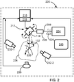
- FIG. 2 is a schematic illustration of a skin treatment system according to an example.
- Skin treatment system 200 includes a treatment energy source 204 that is configured to generate a treatment radiation beam 208.
- Treatment radiation or treatment energy source 204 could be a semiconductor optical energy source such as laser diode, VCSEL, an assembly of laser diodes or bars, a solid state laser, a fiber laser, or other laser energy source with suitable power and wavelengths.
- Treatment energy source 204 could operate at wavelength of visible to NIR (450-2000nm) and provide treatment energy radiation power of 1W to 17kW.
- the treatment energy source 204 in FIG. 2 can be a broad spectrum light source of either coherent or non-coherent radiation such as a Xe, Kr, W, Quartz-Iodine lamps or a LED.
- Treatment radiation beam or simply treatment beam 208 impinges on a treatment beam deflecting mechanism 212 that could be one or more deflecting mirrors, a scanning polygon, a holographic scanning system and a combination of the above.
- the treatment beam deflecting mechanism 212 could be a two dimensional beam deflecting or scanning mechanism,
- the treatment energy beam deflecting mechanism 212 could deflect the treatment beam along one axis X or Y and a linear movement or displacement of the treatment beam deflecting mechanism could be used to scan in the other direction.
- a computer 216 that includes a processor 218 which controls position of the scanning mechanism 212 and is configured to locate treatment beam scanning spot 220 at any coordinate in scanning plane 224.
- Processor 218 also controls the scanning mechanism 212 to produce a plurality of treated skin area scanning patterns and further controls the scanning speed of treatment scanning spot 220 and treatment energy source operation time.
- Control module 216 and in particular processor 218 controls all elements of system 200 including operation time and parameters of treatment energy source 204. It has been noted above that the human or animal skin usually has a three-dimensional contour or profile.
- system 200 includes a dynamic focus module 228, such as HPLK or Pro-series module, commercially available from Cambridge Technology, Inc., Bedford, MA 01730 U.S.A.
- the Dynamic Focus Module (DFM) is used to follow the three-dimensional contour or profile of the human skin and not to flatten the X-Y plane.
- the treatment radiation beam divergence could be changed. The change in divergence would cause a change in the spot size and changes to the treatment radiation intensity delivered by the scanning spot could be introduced.
- the diameter of the scanning spot 220 could be changed up to ten times or even more. The diameter of spot 220 could change for example, from 5 to 30mm.
- Scanning treatment energy spot shape distortion could be compensated among others by changing the size of the scanning spot and/or the amount of fluence delivered into the treatment energy radiation beam.
- the amount of fluence or intensity delivered into the treatment radiation beam could be compensated by providing a treatment intensity roll-off look-up table or by calculating the change in energy in real-time.
- Based on the treatment intensity roll-off look-up table processor 218 adjusts the deflected treatment energy beam intensity to maintain a roll-off the treatment energy beam intensity or fluence of less than 10% (10 percent).
- the look-up table is calculated based on the skin 3D contour and the treatment energy beam incidence angle that is usually less than 30 degrees.
- the scanning system could deliver the treatment energy in a continuous or pulsed mode. Uniform scanning treatment radiation beam distribution on the treated skin area among others could be regulated by processor 218 ( FIG. 2 ) that maintains treatment beam scanning speed to facilitate an overlap of at least 30% between two neighbor treatment scanning spots.
- System 200 further includes a 3D acquisition system 232 (For example, video cameras 232-1 and 232-2) configured to capture a treated skin area or segment and communicate the captured treated skin area image to processor 218.
- the 3D acquisition system 232 also communicates the captured image or images to processor 218, which based on the communicated image or images is configured to reconstruct/determine the three-dimensional (3D) contour of the treated segment or area of the human body.
- the 3D acquisition system 232 could be equipped with an optical zoom system supporting imaging of different sizes of the treated skin area or segment.
- Processor 218 is also configured to construct based on the captured skin area a three-dimensional representation or topography of the captured skin area.
- Processor 218 is further configured to control the treatment energy beam deflecting mechanism to deflect the treatment energy beam to follow the topography or three-dimensional representation of the captured skin area.
- System 200 further includes one or more infrared (IR) cameras or imagers 236 configured to provide processor 218 with a thermal image of the skin affected by the treatment energy radiation.
- Infrared imager 236 could be almost any infrared camera supporting temperature sensitivity of 1°K or better. Infrared imager supports non-contact and non-invasive skin temperature measurement. IR imager or camera 236 could have a resolution sufficient to support imaging of an area of the treated skin segment with dimensions of 30x30cm 2 or smaller.
- Processor 218 is configured to receive the thermal image indicating temperature distribution on the surface of the currently treated by the treatment energy beam skin segment and determine the temperature of the currently treated skin area or segment. Physical properties of human tissue are known and relatively well established.
- Temperature distribution below the skin surface can be calculated based on skin surface temperature and finite elements analyses, using the Bio-heat equation or other suitable numerical and statistical methods known for solving the different heat distribution equations. (For Bio-heat equation details see H.H. Pennes, Analysis of Tissue and Arterial Blood Temperature in the Resting Human Forearm, J. Appl. Phys. vol. 1, pp. 93-122, 1948 ).
- Imager or infrared camera 236 could be equipped by an optical zoom system supporting imaging of a large area or segment of the treated skin or a small area of the treated skin segment.
- System 200 further includes a display 240.
- Processor 218 based on the signals received from the infrared imager 236 continuously or at predetermined intervals updates the displayed thermal image of the treated skin segment. Based on the signals received from the 3D acquisition system 232, processor 218 issues corrections to the treatment energy spot and treatment energy beam location to follow the skin contour.
- Display 240 is configured to receive from processor 218 the thermal image of the treated skin segment and to display the temperature of the skin segment or thermal map 300 ( FIG. 3 ) of the treated by the skin treatment energy skin segment. Display of the image captured by the 3D acquisition system facilitates visual control of the process by the caregiver.
- the image provided by 3D acquisition system 232 could include area larger than the treated skin areas and include surrounding the skin treatment area skin segments.
- FIG. 3 is a schematic illustration of an image displayed on the display of the present system for skin treatment according to an example.
- Image 300 shows area 304 with a homogenous skin temperature that could be a desired treatment temperature.
- Areas 308 - 316 illustrate segments of skin having temperature different from the desired treatment temperature. The temperature could be higher or lower than the desired treatment temperature and each area 308 - 316 could have a different temperature.
- Display 240 is also configured to receive from computer 218 processor 216 ( FIG. 2 ) the thermal image of the treated skin segment and the current or most recent location of the scanning treatment energy spot 220, within the treated by the skin treatment energy skin segment.
- control of the treatment process and of the scanning system could be simplified by forming a specific scanning geometry, for example, limiting the treatment energy beam incidence angle to 20, 15 or 10 degrees. At such treatment energy beam incident angles, scanned treatment energy power is almost constant and skin topography does not change significantly.
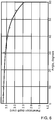
- FIG. 4 is an example illustrating dependence of incident electromagnetic radiation beam fluence as a function of the incident angle on a turbid media.
- the electromagnetic radiation could be a laser beam.
- Turbid media was simulating human tissue or skin and was produced/simulated by different concentration of milk in water. The figure ( FIG. 4 ) shows that in highly concentrated turbid media at incidence angles from 0 degrees to about 30 degrees the fluence of the laser beam does not significantly change.
- FIG. 5 is an illustration of the incident electromagnetic energy beam fluence distribution in the XZ plane (in the depth of the turbid media) at different electromagnetic energy beam incident angles.
- the crosshatched area is an area with maximal electromagnetic energy beam fluence.
- the fluence distribution pattern does not manifests visible asymmetry.
- FIG. 6 is an example illustrating dependence of the electromagnetic radiation beam, such as a laser beam, penetration depth into a turbid media as a function of incidence angle.
- the figure clear shows that for incidence angles ranging from 0° (zero degrees) to about 40° (degrees) the penetration depth of the laser beam into a turbid media is weakly dependent on the laser beam incidence angle.
- FIG. 4 and FIG. 6 solid line marks measured values and round dots mark calculated values. Experimental results have been obtained using a Nd:YAG (532 nm) and a laser diode (800 nm) electromagnetic radiation.
- FIG. 7 is a schematic illustration of an example of skin temperature distribution when it is irradiated by a treatment radiation.
- Treatment radiation scanning beam scans the skin surface from which the treatment energy penetrates into deeper skin layers and heats for example, hair roots, adipose tissue and collagen.
- Prolonged heating for example 30 to 50min of the target skin areas (e. g. hair roots, adipose tissue) and maintenance of the target areas at a constant relatively low skin temperature of for example, 40 degrees Celsius, causes the desired skin treatment effect.
- the effect could be hair removal, adipose tissue reduction, wrinkle reduction and other.
- some skin areas could have a temperature higher or lower than the desired treatment temperature. Skin areas with higher temperature could be cooled.
- Fig. 8 illustrates an example of a cryogenic cooling device for cooling large skin area.
- Cryogenic cooling device includes two bars 804 and 808 ( FIG. 8A - 8B ) spaced apart with a plurality of nozzles through which cryogenic gas or cold air, schematically shown in FIG. 8C by arrows 812, is directed to skin surface 816.
- Treatment energy radiation 820 is directed into space 824 between bars 804 and 808.
- Bars 804 and 808 could move in a synchronous or asynchronous movement mode following the treatment radiation beam and changing width of space 824 between bars 804 and 808.
- Bars 804 and 808 could be of straight shape or a have a type of arched or curvilinear shape ( FIG. 8C ) to approximate the shape of the treated skin area.
- FIG. 9 is an example of a workflow of the skin treatment by the present system for skin treatment.
- operator or caregiver sets the desired treatment beam fluence (Block 904).
- Proper fluence values could be achieved by setting treatment radiation power from 1.0W to 10kW.
- Concurrently treatment radiation pulse duration is set to be 1msec to 1 sec or CW operation.
- the operator determines topography or 3D profile of the scanned surface. Given the topography of the scanned surface, it is possible to set the distance from the deflection module to the treated skin segment (Block 912).
- the operator sets the treatment radiation power and other treatment radiation parameters to meet the change in the distance to the treated skin segment (Block 916).
- changes to beam divergence or focal length of lens 128 could take place. Changes in beam divergence or focal length could control the size of the scanning spot 220 ( FIG. 2 ) formed by the treatment beam. Spot 220 could change from 5 to 30mm.
- a video camera 232 could be used to validate (Block 920) the distance to the treated skin surface.
- control of the distance between the scanning mechanism and the treated skin surface could be performed based on the dimensions/size of the treated body.
- Image sensors such as video cameras 232 ( FIG. 2 ) could be adapted to provide the desired information to processor 218 that would execute a proper algorithm supporting determination of the dimensions/size of the treated body.
- the treatment process settings and control could be simplified by using prepared ahead of time standard skin treatment procedures parameters.
- the procedures could be stored in the memory as a Look-up-Table (LUT) of computer 216 ( FIG. 2 ), which controls the process of the skin treatetment.
- LUT Look-up-Table
Description
- The present description relates to a system for aesthetic treatment of a human cutaneous and subcutaneous tissue and in particular for treatment of large segments of tissue.
- Tissue is frequently treated non-invasively by different energies delivered to the skin. Types of energies that may be found in use for skin treatment include ultra sound (US) energy, Radio Frequency (RF) energy, microwave (MW) radiation or radiation energy emitted by a source of light or heat. The skin treatment energy is coupled to the skin by an applicator. The spot-size of the applicator is the area of the interface for delivering the energy and it defines to some extent the segment of skin or tissue to which the skin treatment energy is transferred. In order to treat another skin segments, the applicator is repositioned or re-aligned across a larger segment of the skin and activated to couple treatment energy to this segment of skin. The size of a treated segment of skin varies from about 3x3mm2 to about 30x30mm2.
- After applying treatment to a specific skin segment the remaining segments of the skin are treated by moving or repositioning the applicator across a larger skin segment. A caregiver providing the skin treatment manually repositions the applicator. Although the time of skin treatment energy delivery could be controlled, other parameters would much depend on the expertise of the caregiver such as treated area overlap, quality of the contact, pressure applied to the applicator etc... As a result, not all skin segments are treated uniformly and evenly.
- The human or animal skin has a three-dimensional contour and in addition to the caregiver errors, the skin contour complicates proper applicator positioning on the skin and optimal coupling or delivery of tissue or skin affecting energy.
- The skin treatment usually continues for tens of minutes (20 - 60 minutes) depending on the treatment area size and naturally causes some fatigue to the caregiver. Reliance on the caregiver expertise for repositioning of the applicator frequently causes some of the skin treated areas to receive a lower than desired portion of energy and be at a temperature lower than the optimal treatment temperature, while other skin areas could receive a larger than desired portion of energy and be at a temperature higher than the optimal treatment temperature. Relevant prior art is disclosed by
US2010/063490A1 ,US2015/025513A1 ,US2013/261606A1 ,US RE37504E andUS2013/345541A1 . - The term "skin" as used in the present disclosure includes the outer skin layers such as stratum corneum, dermis, epidermis, connective tissue and the deeper subcutaneous layers such as adipose tissue. The terms "tissue" or "skin" as used in the present disclosure have the same meaning and are used interchangeable through the text of the disclosure.
- The term "skin treatment energy" as used in the present disclosure means electromagnetic energy delivered to the skin by a treatment energy application device.
- The term "treatment energy source" may be a laser source, for example a semiconductor laser such as laser diode, VCSEL, an assembly of laser diodes or bars or a solid state laser such as an Nd:YAG or Alexandrite for example, or a fiber laser, or other laser source or sources. The treatment energy source may be a broad spectrum light source of either coherent or non-coherent radiation source such as a Xe, Kr, W, Quartz-Iodine lamps or a high power LED. In some examples the treatment energy source maybe microwave energy source or sources.
- The term "scanning angle" as used in the present disclosure means half the angle between the extreme scanning beam locations on the skin of the incident treatment energy beam and the energy source or scanning mirror/deflector. In the case the energy source is a ultrasound phased array the "scanning angle" will mean half the angle between the extreme scanning locations of the incident treatment energy beam on the skin and the phase center of the array, which is the location that the radiation appears to emanate. The scanning angle defines the length of a treatment energy beam sweep on the skin. In some examples the scanning angle of the same scanning system could be a variable angle characterizing a shorter or a longer treatment energy beam sweep.
- The term "incidence angle" as used in the present disclosure means an angle between the treatment energy beam and the skin at each of the locations the beam impinges the skin.
- The term "tissue/skin affecting energy" or "treatment energy" as used in the present disclosure means energy capable of causing a change in the tissue including heating and affecting hair follicles, hair papillae, sebaceous glands, fat cells, blood vessels, connective tissue, or supporting such change. Such energy for example, may be optical radiation in visible or invisible part of electromagnetic spectrum. The exact parameters of the energy source such as power, fluence, wavelength, etc., may be chosen depending on the specific application and clinical effect to target tissue.
- The term "target tissue temperature" as used in the present disclosure means temperature of the targeted tissue such as dermis, hair follicle, hair papillae, sebaceous glands, fat cells, blood vessel, pigmented lesion, adipose or deeper subcutaneous tissue. The temperature of the target tissue could be derived based on the temperature of the skin overlaying the target tissue.
- The term "computer" as used in the present disclosure means a computer including a processing unit capable of receiving data or information, processing it, and delivering the data processing results to another device. As such, a computer may include, as nonlimiting examples, a personal computer, a PDA computer, a mobile telephone, a micro controller and similar devices. Typically, a computer as defined herein would have a display or communicate with a display. The display could be a touch type of display such that the caregiver could use the display to enter commands or a monitor screen that displays information and images.
- The term "three-dimensional (3D) Acquisition system" as used in the present disclosure means a device that acquires data to reconstruct a surface contour. It may include one or more cameras and may include a projector to project a light structure.
- A system for skin treatment including a treatment energy source that generates a treatment beam. A treatment beam deflecting mechanism is configured to direct the treatment beam to a treated skin area. One or more video cameras are configured to capture a treated skin area and communicate the captured treated skin area image to a processor. The processor is configured to construct, based on a captured treated skin area a three-dimensional (3D) representation of the captured treated skin area. The processor is further configured to control a treatment beam deflecting mechanism to deflect the treatment beam to follow the three-dimensional representation of the captured skin area.
- The system for skin treatment includes an infrared imager configured to capture an infrared image of the treated skin area captured by the at least one video camera and communicate the infrared image of the treated skin area to the processor. Based on the infrared image of the treated skin area, the processor is also configured to assess the temperature of adipose tissue located below the treated skin area.
-
-
FIG. 1 is an example of an existing skin treatment laser scanning system; -
FIG. 2 is a schematic illustration of a skin treatment energy delivering scanning system according to an example; -
FIG. 3 is a schematic illustration of an image displayed on the display of the present system for skin treatment according to an example; -
FIG. 4 is an example illustrating dependence of incident electromagnetic radiation beam fluence as a function of the incident angle on a turbid media; -
FIG. 5 is an example illustrating dependence of the electromagnetic energy beam fluence distribution as function of the incident angle in the XZ plane; -
FIG. 6 is an example illustrating dependence of the electromagnetic radiation beam, such as a laser beam, penetration depth into a turbid media as function of incident angle; -
FIG. 7 is a schematic illustration of an example of skin temperature distribution when it is irradiated by a treatment energy radiation; -
Fig. 8 illustrates an example of a cryogenic cooling device for cooling large skin area; and -
FIG. 9 is an example of a workflow of the skin treatment by the present system for skin treatment. - Currently, most of the skin treatments by electromagnetic energy and in particular by light are performed by an applicator that when applied to the skin affects an area of 3x3mm2 and up to 30x30mm2. In order to treat other skin segments or areas, the applicator is repositioned or re-aligned across a large segment of the skin and activated to deliver or couple tissue or skin affecting or treatment energy to this segment of skin. Proper skin treatment and in particular adipose tissue treatment for circumference reduction would provide better results if efficient, homogenous affecting energy delivery over a relatively large skin areas or segments could be performed.
- It has been found that it would be advantageous to affect simultaneously or almost simultaneously a large skin area without involving hand motion and applicator repositioning by the caregiver.
- The present disclosure suggests an efficient, homogenous and almost simultaneous skin treatment energy delivery apparatus over a relatively large skin areas or segments of skin. Treatment energy beam scanning provided by a deflecting mirror or a rotating polygon supports almost simultaneous delivery of the skin treatment or skin affecting energy across a large area of skin. Overlap of the scanning spot formed by the treatment energy beam along the scanning path removes non-uniformities caused by any none-uniform energy distribution or hot-spots in the treatment energy beam pass. Application of treatment energy by scanning the treatment energy beam makes the skin treatment less dependent or almost not dependent on the caregiver's expertise and reduces the treatment time considerably.
- An additional advantage of the treatment energy beam scanning is that it supports variability in position of the scanning spot in all three dimensions/axes. Treatment energy beam spot could be easily positioned at almost any location on the skin in X-Y plane and also moved over relatively large distance in direction of Z axis or depth.
- The need to accurately identify the temperature readings or representation of target tissue temperature across the treated skin area under such conditions may represent a serious challenge to any caregiver. The present document also discloses a method of target tissue temperature determination in course of the skin treatment.
- As light energy is absorbed rapidly when penetrating the skin, heating of the superficial layers of the skin is inevitable. In order to eliminate the risk of undesired harmful effect of the epidermis and dermis one may use a number of cooling methods such as contact cooling, dynamic-cooling, air-cooling, cryogenic cooling and other known in the art cooling methods. These epidermal protection methods cool the skin in any combination of before, during and after the delivery of light energy to the skin. So the temperature rise within the epidermal and dermal layer is below the threshold of harming the tissue, while still reaching desired treatment temperature in the targeted tissue.
- Monitoring the temporal change of the skin temperature could be done by using a thermal camera, IR temperature sensor, ultrasound propagation speed temperature monitoring, contact temperature sensors, non-contact temperature sensing device, or any other means that can be used to assess the temperature in the target tissue. This could be achieved by measuring the amount of heat that has dissipated from the target to the skin and then cooled by either normal air convection of the skin or by taking into account the temporal dynamics of bio-heat equation for the entire treated skin area.
- Another advantage of using a scanning treatment energy beam is the ability for continuous control of a large number of variables available in course of the skin treatment. This could include distribution of energy in each of wavelengths of the treatment radiation beam, the spot/area formed by irradiating the skin treatment beam, overlap between two neighbor treatment spots, treatment energy level, exposure duration per unit area or continuous irradiation, selected treatment duration and adaptation to treated skin/tissue area characteristics.
- In some examples, the energy dose delivered by a scanning treatment beam spot could be set to cause immediate detectable temperature rise of the treated tissue. In other examples of the apparatus disclosed, the energy dose delivered by a scanning treatment beam spot could be set to cause a slow, immediately not detectable temperature rise of the treated tissue, such that the treated and surrounding tissue is heated but not damaged.
- The scanning system could deliver the treatment energy in a continuous or pulsed mode. Uniform scanning treatment beam intensity or fluence distribution and location on the treated skin area among others could be regulated by processor 218 (
FIG. 2 ) that maintains treatment beam scanning speed to facilitate an overlap of at least 30% between two neighbor treatment scanning spots. - In a further example, the treatment beam scanning speed could be set to match the thermal relaxation time and perfusion rate of the targeted skin/tissue, such as dependent on the size of the treated area and desired temperature to be maintained, or a homogenous desired skin temperature is maintained for a certain volume of targeted tissue.
- Reference is made to
FIG. 1 which is an example of an existing skin treatment laser scanning system.Skin treatment system 100 includes atreatment energy source 104 that provides atreatment radiation beam 108.Treatment radiation beam 108 impinges on a treatment beam deflecting orscanning mechanism 112 that could be one or more of flat or concave deflecting mirrors, a scanning polygon, a holographic disk and a combination of the above. Acontrol module 116 controls position of thescanning mechanism 112 and is configured to locatetreatment scanning spot 120 at any coordinate inX-Y scanning plane 124.System 100 could also include alens 128 that could be a flat field lens or a regular lens or lens array depending on the length or angle of the treatment beam scanning and the depth profile of the treated skin. In someexamples lens 128 could be a beam expander\reducer matching the spot size on the skin with a treatment plan or protocol. - When
treatment energy beam 108 is directed to scan across the skin the actual spot size produced by the treatment beam intensity may change due to change in the incidence angle and the skin curvature at any location on skin, the fluence of the treatment energy changed in order to compensate and reach the desired treatment energy intensity by temporarily increasing the source power. -
FIG. 2 is a schematic illustration of a skin treatment system according to an example.Skin treatment system 200 includes atreatment energy source 204 that is configured to generate atreatment radiation beam 208. Treatment radiation ortreatment energy source 204 could be a semiconductor optical energy source such as laser diode, VCSEL, an assembly of laser diodes or bars, a solid state laser, a fiber laser, or other laser energy source with suitable power and wavelengths.Treatment energy source 204 could operate at wavelength of visible to NIR (450-2000nm) and provide treatment energy radiation power of 1W to 17kW. Thetreatment energy source 204 inFIG. 2 can be a broad spectrum light source of either coherent or non-coherent radiation such as a Xe, Kr, W, Quartz-Iodine lamps or a LED. Treatment radiation beam or simplytreatment beam 208 impinges on a treatmentbeam deflecting mechanism 212 that could be one or more deflecting mirrors, a scanning polygon, a holographic scanning system and a combination of the above. In one example, the treatmentbeam deflecting mechanism 212 could be a two dimensional beam deflecting or scanning mechanism, In a further example, the treatment energybeam deflecting mechanism 212 could deflect the treatment beam along one axis X or Y and a linear movement or displacement of the treatment beam deflecting mechanism could be used to scan in the other direction. - A
computer 216 that includes aprocessor 218 which controls position of thescanning mechanism 212 and is configured to locate treatmentbeam scanning spot 220 at any coordinate inscanning plane 224.Processor 218 also controls thescanning mechanism 212 to produce a plurality of treated skin area scanning patterns and further controls the scanning speed oftreatment scanning spot 220 and treatment energy source operation time.Control module 216 and inparticular processor 218 controls all elements ofsystem 200 including operation time and parameters oftreatment energy source 204. It has been noted above that the human or animal skin usually has a three-dimensional contour or profile. In one example,system 200 includes adynamic focus module 228, such as HPLK or Pro-series module, commercially available from Cambridge Technology, Inc., Bedford, MA 01730 U.S.A. However, in the current disclosure the Dynamic Focus Module (DFM) is used to follow the three-dimensional contour or profile of the human skin and not to flatten the X-Y plane. In order to compensate for any change in the curvature of the skin and deliver the prescribed fluence or power dose, the treatment radiation beam divergence could be changed. The change in divergence would cause a change in the spot size and changes to the treatment radiation intensity delivered by the scanning spot could be introduced. By changingtreatment radiation beam 208 divergence, the diameter of thescanning spot 220 could be changed up to ten times or even more. The diameter ofspot 220 could change for example, from 5 to 30mm. - The scanning or treatment energy beam sweep angle and 3D (three dimensional) nature of human body distort to certain degree the scanning treatment spot shape and cause a treatment beam intensity roll-off at peripheral treatment beams. Scanning treatment energy spot shape distortion could be compensated among others by changing the size of the scanning spot and/or the amount of fluence delivered into the treatment energy radiation beam. The amount of fluence or intensity delivered into the treatment radiation beam could be compensated by providing a treatment intensity roll-off look-up table or by calculating the change in energy in real-time. Based on the treatment intensity roll-off look-up
table processor 218 adjusts the deflected treatment energy beam intensity to maintain a roll-off the treatment energy beam intensity or fluence of less than 10% (10 percent). The look-up table is calculated based on theskin 3D contour and the treatment energy beam incidence angle that is usually less than 30 degrees. The scanning system could deliver the treatment energy in a continuous or pulsed mode. Uniform scanning treatment radiation beam distribution on the treated skin area among others could be regulated by processor 218 (FIG. 2 ) that maintains treatment beam scanning speed to facilitate an overlap of at least 30% between two neighbor treatment scanning spots. -
System 200 further includes a 3D acquisition system 232 (For example, video cameras 232-1 and 232-2) configured to capture a treated skin area or segment and communicate the captured treated skin area image toprocessor 218. The 3D acquisition system 232 also communicates the captured image or images toprocessor 218, which based on the communicated image or images is configured to reconstruct/determine the three-dimensional (3D) contour of the treated segment or area of the human body. The 3D acquisition system 232 could be equipped with an optical zoom system supporting imaging of different sizes of the treated skin area or segment.Processor 218 is also configured to construct based on the captured skin area a three-dimensional representation or topography of the captured skin area.Processor 218 is further configured to control the treatment energy beam deflecting mechanism to deflect the treatment energy beam to follow the topography or three-dimensional representation of the captured skin area. -
System 200 further includes one or more infrared (IR) cameras orimagers 236 configured to provideprocessor 218 with a thermal image of the skin affected by the treatment energy radiation.Infrared imager 236 could be almost any infrared camera supporting temperature sensitivity of 1°K or better. Infrared imager supports non-contact and non-invasive skin temperature measurement. IR imager orcamera 236 could have a resolution sufficient to support imaging of an area of the treated skin segment with dimensions of 30x30cm2 or smaller.Processor 218 is configured to receive the thermal image indicating temperature distribution on the surface of the currently treated by the treatment energy beam skin segment and determine the temperature of the currently treated skin area or segment. Physical properties of human tissue are known and relatively well established. Temperature distribution below the skin surface can be calculated based on skin surface temperature and finite elements analyses, using the Bio-heat equation or other suitable numerical and statistical methods known for solving the different heat distribution equations.
(For Bio-heat equation details see H.H. Pennes, Analysis of Tissue and Arterial Blood Temperature in the Resting Human Forearm, J. Appl. Phys. vol. 1, pp. 93-122, 1948). - Without forming part of the invention, methods of assessing temperature inside the body by analyzing the radiation reflection spectrum or any other known in the art method could be used to assess temperature of the adipose tissue located below the skin. Real-time temperature monitoring facilitates safe and effective skin treatment.
- Imager or
infrared camera 236 could be equipped by an optical zoom system supporting imaging of a large area or segment of the treated skin or a small area of the treated skin segment. -
System 200 further includes adisplay 240.Processor 218 based on the signals received from theinfrared imager 236 continuously or at predetermined intervals updates the displayed thermal image of the treated skin segment. Based on the signals received from the 3D acquisition system 232,processor 218 issues corrections to the treatment energy spot and treatment energy beam location to follow the skin contour. -
Display 240 is configured to receive fromprocessor 218 the thermal image of the treated skin segment and to display the temperature of the skin segment or thermal map 300 (FIG. 3 ) of the treated by the skin treatment energy skin segment. Display of the image captured by the 3D acquisition system facilitates visual control of the process by the caregiver. The image provided by 3D acquisition system 232 could include area larger than the treated skin areas and include surrounding the skin treatment area skin segments. -
FIG. 3 is a schematic illustration of an image displayed on the display of the present system for skin treatment according to an example.Image 300 showsarea 304 with a homogenous skin temperature that could be a desired treatment temperature. Areas 308 - 316 illustrate segments of skin having temperature different from the desired treatment temperature. The temperature could be higher or lower than the desired treatment temperature and each area 308 - 316 could have a different temperature. -
Display 240 is also configured to receive fromcomputer 218 processor 216 (FIG. 2 ) the thermal image of the treated skin segment and the current or most recent location of the scanningtreatment energy spot 220, within the treated by the skin treatment energy skin segment. - In some examples control of the treatment process and of the scanning system could be simplified by forming a specific scanning geometry, for example, limiting the treatment energy beam incidence angle to 20, 15 or 10 degrees. At such treatment energy beam incident angles, scanned treatment energy power is almost constant and skin topography does not change significantly.
-
FIG. 4 is an example illustrating dependence of incident electromagnetic radiation beam fluence as a function of the incident angle on a turbid media. The electromagnetic radiation could be a laser beam. Turbid media was simulating human tissue or skin and was produced/simulated by different concentration of milk in water. The figure (FIG. 4 ) shows that in highly concentrated turbid media at incidence angles from 0 degrees to about 30 degrees the fluence of the laser beam does not significantly change. -
FIG. 5 is an illustration of the incident electromagnetic energy beam fluence distribution in the XZ plane (in the depth of the turbid media) at different electromagnetic energy beam incident angles. The electromagnetic energy beam had a radius R=8mm. The crosshatched area is an area with maximal electromagnetic energy beam fluence. The fluence distribution pattern does not manifests visible asymmetry. -
FIG. 6 is an example illustrating dependence of the electromagnetic radiation beam, such as a laser beam, penetration depth into a turbid media as a function of incidence angle. The figure clear shows that for incidence angles ranging from 0° (zero degrees) to about 40° (degrees) the penetration depth of the laser beam into a turbid media is weakly dependent on the laser beam incidence angle. - In
FIG. 4 andFIG. 6 solid line marks measured values and round dots mark calculated values. Experimental results have been obtained using a Nd:YAG (532 nm) and a laser diode (800 nm) electromagnetic radiation. -
FIG. 7 is a schematic illustration of an example of skin temperature distribution when it is irradiated by a treatment radiation. Treatment radiation scanning beam scans the skin surface from which the treatment energy penetrates into deeper skin layers and heats for example, hair roots, adipose tissue and collagen. Prolonged heating, for example 30 to 50min of the target skin areas (e. g. hair roots, adipose tissue) and maintenance of the target areas at a constant relatively low skin temperature of for example, 40 degrees Celsius, causes the desired skin treatment effect. The effect could be hair removal, adipose tissue reduction, wrinkle reduction and other. As it has been illustrated inFIG. 3 some skin areas could have a temperature higher or lower than the desired treatment temperature. Skin areas with higher temperature could be cooled. -
Fig. 8 illustrates an example of a cryogenic cooling device for cooling large skin area. Cryogenic cooling device includes twobars 804 and 808 (FIG. 8A - 8B ) spaced apart with a plurality of nozzles through which cryogenic gas or cold air, schematically shown inFIG. 8C byarrows 812, is directed toskin surface 816.Treatment energy radiation 820 is directed intospace 824 betweenbars Bars space 824 betweenbars Bars FIG. 8C ) to approximate the shape of the treated skin area. -
FIG. 9 is an example of a workflow of the skin treatment by the present system for skin treatment. Initially, operator or caregiver sets the desired treatment beam fluence (Block 904). Proper fluence values could be achieved by setting treatment radiation power from 1.0W to 10kW. Concurrently treatment radiation pulse duration is set to be 1msec to 1 sec or CW operation. Atblock 908 the operator determines topography or 3D profile of the scanned surface. Given the topography of the scanned surface, it is possible to set the distance from the deflection module to the treated skin segment (Block 912). The operator sets the treatment radiation power and other treatment radiation parameters to meet the change in the distance to the treated skin segment (Block 916). In some examples in addition to change in the distance to the treated skin segment treatment changes to beam divergence or focal length oflens 128 also could take place. Changes in beam divergence or focal length could control the size of the scanning spot 220 (FIG. 2 ) formed by the treatment beam.Spot 220 could change from 5 to 30mm. Upon completion of the settings a video camera 232 could be used to validate (Block 920) the distance to the treated skin surface. - According to another example, control of the distance between the scanning mechanism and the treated skin surface could be performed based on the dimensions/size of the treated body. Image sensors, such as video cameras 232 (
FIG. 2 ) could be adapted to provide the desired information toprocessor 218 that would execute a proper algorithm supporting determination of the dimensions/size of the treated body. - In some examples the treatment process settings and control could be simplified by using prepared ahead of time standard skin treatment procedures parameters. The procedures could be stored in the memory as a Look-up-Table (LUT) of computer 216 (
FIG. 2 ), which controls the process of the skin treatetment. - While the apparatus has been particularly shown and described with references to some examples thereof, it will be understood by those skilled in the art that various changes in form and details may be made therein without departing from the scope of the apparatus encompassed by the appended claims.
Claims (10)
- A system comprising:at least one treatment energy source (104, 204) for generating a treatment beam (108, 208);at least one treatment beam (108, 208) deflecting mechanism (112, 212) configured to direct the treatment beam (108, 208) to a treated skin area;at least one video camera (236) configured to capture a treated skin area and communicate captured treated skin area image to a processor (218); anda processor (218) configured to construct, based on a captured treated skin area a three-dimensional representation of the captured treated skin area and wherein the processor (218) is further configured to control a treatment beam deflecting mechanism (112, 212) to deflect the treatment beam (108, 208) to follow the three-dimensional representation of the captured skin area,characterized in that the system further comprises:
a treatment beam (108, 208) intensity roll-off look-up table, wherein the processor (218) is configured to adjust a deflected treatment beam (108, 208) intensity based on the treatment beam intensity roll-off look-up table. - The system according to claim 1 further comprising an infrared imager (236) configured to capture an infrared image (300) of the treated skin area captured by the at least one video camera (236) and communicate the infrared image (300) of the treated skin area to the processor (218) and wherein the processor (218) is also configured based on the infrared image (300) of the treated skin area to assess at least temperature of adipose tissue located below the treated skin area.
- The system according to claim 1 wherein scanning angle of the treatment beam (108, 208) is less than 30 degrees and wherein treatment beam (108, 208) intensity roll-off is less than 10 percent.
- The system according to claim 1 wherein the processor (218) controls a treatment beam deflecting mechanism (112, 212) to produce a plurality of treated skin area scanning patterns and wherein the processor (218) also controls a treatment beam (108, 208) scanning speed.
- The system according to claim 1 wherein treatment beam (108, 208) intensity and scanning speed are selected to support temperature of adipose tissue located below the treated skin area at at least 40 degrees Celsius.
- The system according to claim 1 wherein a treatment beam (108, 208) intensity varies along a scanning angle.
- The system according to claim 1 wherein the treatment energy source delivers treatment energy in a continuous or pulsed mode, and preferably wherein a temperature sensing device is a non-contact temperature measuring device.
- The system according to claim 1 wherein the treatment beam deflecting mechanism (112, 212) is at least one of a group of elements consisting of a flat mirror, concave mirror, holographic element and a rotating polygon.
- The system according to claim 1 wherein the scanning treatment beam forms a scanning spot (120, 220) on the treated skin area and wherein the processor (218) maintains treatment beam (108, 208) scanning speed to maintain an overlap of at least 30% between two neighbor treatment spots.
- The system according to claim 1 wherein a treatment beam (108, 208) scanning speed is set:
to match a thermal relaxation time and perfusion rate of a targeted skin and/or according to size of the treated area and desired temperature to be maintained.
Applications Claiming Priority (2)
| Application Number | Priority Date | Filing Date | Title |
|---|---|---|---|
| US201662286458P | 2016-01-25 | 2016-01-25 | |
| PCT/IL2017/050005 WO2017130185A2 (en) | 2016-01-25 | 2017-01-01 | Skin treatment apparatus and method |
Publications (3)
| Publication Number | Publication Date |
|---|---|
| EP3407961A2 EP3407961A2 (en) | 2018-12-05 |
| EP3407961A4 EP3407961A4 (en) | 2019-11-20 |
| EP3407961B1 true EP3407961B1 (en) | 2021-07-14 |
Family
ID=59397576
Family Applications (1)
| Application Number | Title | Priority Date | Filing Date |
|---|---|---|---|
| EP17743839.7A Active EP3407961B1 (en) | 2016-01-25 | 2017-01-01 | Skin treatment apparatus |
Country Status (3)
| Country | Link |
|---|---|
| US (1) | US20180271597A1 (en) |
| EP (1) | EP3407961B1 (en) |
| WO (1) | WO2017130185A2 (en) |
Families Citing this family (5)
| Publication number | Priority date | Publication date | Assignee | Title |
|---|---|---|---|---|
| US8357150B2 (en) | 2009-07-20 | 2013-01-22 | Syneron Medical Ltd. | Method and apparatus for fractional skin treatment |
| WO2018211492A1 (en) | 2017-05-18 | 2018-11-22 | Lightfective Ltd. | Methods and devices for treatment of subcutaneous fat |
| SG11202005218TA (en) | 2017-12-14 | 2020-07-29 | Avava Inc | Electromagnetic radiation beam scanning system and method |
| KR20220052317A (en) * | 2019-06-13 | 2022-04-27 | 도미니언 에스테틱 테크놀로지스, 인크. | Systems and methods for cosmetic treatment |
| CN112915398B (en) * | 2021-03-18 | 2023-05-30 | 江苏集萃有机光电技术研究所有限公司 | Face infrared physiotherapy method, device, equipment, system and mask |
Family Cites Families (8)
| Publication number | Priority date | Publication date | Assignee | Title |
|---|---|---|---|---|
| USRE37504E1 (en) * | 1992-12-03 | 2002-01-08 | Lasersight Technologies, Inc. | Ophthalmic surgery method using non-contact scanning laser |
| US6149644A (en) * | 1998-02-17 | 2000-11-21 | Altralight, Inc. | Method and apparatus for epidermal treatment with computer controlled moving focused infrared light |
| US8308717B2 (en) * | 2004-06-21 | 2012-11-13 | Seilex Ltd | Thermal energy applicator |
| US8821482B2 (en) * | 2006-06-26 | 2014-09-02 | Koninklijke Philips N.V. | Device and method for the treatment of skin, and use of the device |
| US20130261606A1 (en) * | 2007-04-30 | 2013-10-03 | Andrew Technologies Llc | Harvesting Fat Tissue Using Tissue Liquefaction |
| US20130345541A1 (en) * | 2012-06-26 | 2013-12-26 | Covidien Lp | Electrosurgical device incorporating a photo-acoustic system for interrogating/imaging tissue |
| US20140303608A1 (en) * | 2013-04-08 | 2014-10-09 | Scientific Image Center Management, Inc. | System and method for providing treatment feedback for a thermal treatment device |
| WO2015126988A1 (en) * | 2014-02-18 | 2015-08-27 | Tria Beauty, Inc. | Internet connected dermatological devices and systems |
-
2017
- 2017-01-01 WO PCT/IL2017/050005 patent/WO2017130185A2/en active Application Filing
- 2017-01-01 EP EP17743839.7A patent/EP3407961B1/en active Active
- 2017-01-01 US US15/781,501 patent/US20180271597A1/en not_active Abandoned
Also Published As
| Publication number | Publication date |
|---|---|
| US20180271597A1 (en) | 2018-09-27 |
| WO2017130185A2 (en) | 2017-08-03 |
| EP3407961A4 (en) | 2019-11-20 |
| WO2017130185A3 (en) | 2017-11-23 |
| EP3407961A2 (en) | 2018-12-05 |
Similar Documents
| Publication | Publication Date | Title |
|---|---|---|
| EP3407961B1 (en) | Skin treatment apparatus | |
| US7083611B2 (en) | Method and apparatus for providing facial rejuvenation treatments | |
| JP4335209B2 (en) | Method and apparatus for treating skin using light energy patterns | |
| CN109688964B (en) | Automated system and method for hair removal | |
| US10299871B2 (en) | Automated system and method for hair removal | |
| KR101649959B1 (en) | Galvano Scanner control and epilation Treatment Handpiece using Pore recognition | |
| JP6509829B2 (en) | Measuring device for skin characteristics and non-invasive processing device | |
| US20230405355A1 (en) | Image guided laser therapy | |
| JP2023501980A (en) | Feedback detection for therapeutic devices | |
| US10850115B2 (en) | Systems and methods for medical treatment using a series of pulsed lasers | |
| KR101716317B1 (en) | A treatment apparatus and a method for controlling the optical apparatus | |
| KR20160122581A (en) | Laser irradiator for skin treatment and medical treatment method thereof | |
| CN112165893A (en) | Diffractive optics for EMR-based tissue treatment | |
| KR20220103094A (en) | Pulse irradiation method and pulse irradiation apparatus | |
| US20240108408A1 (en) | Treatment apparatus | |
| JPWO2006030622A1 (en) | Laser therapy equipment | |
| KR20160122585A (en) | Laser irradiator for skin treatment and medical treatment method thereof | |
| Gassem et al. | Real time control of the spatial selectivity during laser treatment of a biological surface |
Legal Events
| Date | Code | Title | Description |
|---|---|---|---|
| STAA | Information on the status of an ep patent application or granted ep patent |
Free format text: STATUS: THE INTERNATIONAL PUBLICATION HAS BEEN MADE |
|
| PUAI | Public reference made under article 153(3) epc to a published international application that has entered the european phase |
Free format text: ORIGINAL CODE: 0009012 |
|
| STAA | Information on the status of an ep patent application or granted ep patent |
Free format text: STATUS: REQUEST FOR EXAMINATION WAS MADE |
|
| 17P | Request for examination filed |
Effective date: 20180817 |
|
| AK | Designated contracting states |
Kind code of ref document: A2 Designated state(s): AL AT BE BG CH CY CZ DE DK EE ES FI FR GB GR HR HU IE IS IT LI LT LU LV MC MK MT NL NO PL PT RO RS SE SI SK SM TR |
|
| AX | Request for extension of the european patent |
Extension state: BA ME |
|
| STAA | Information on the status of an ep patent application or granted ep patent |
Free format text: STATUS: REQUEST FOR EXAMINATION WAS MADE |
|
| DAV | Request for validation of the european patent (deleted) | ||
| DAX | Request for extension of the european patent (deleted) | ||
| A4 | Supplementary search report drawn up and despatched |
Effective date: 20191023 |
|
| RIC1 | Information provided on ipc code assigned before grant |
Ipc: A61N 5/067 20060101ALN20191017BHEP Ipc: A61N 5/06 20060101ALN20191017BHEP Ipc: A61B 18/20 20060101AFI20191017BHEP Ipc: A61B 18/22 20060101ALN20191017BHEP Ipc: A61B 18/00 20060101ALN20191017BHEP |
|
| RIC1 | Information provided on ipc code assigned before grant |
Ipc: A61B 18/20 20060101AFI20201223BHEP Ipc: A61N 5/067 20060101ALN20201223BHEP Ipc: A61B 18/00 20060101ALN20201223BHEP Ipc: A61N 5/06 20060101ALN20201223BHEP Ipc: A61B 18/22 20060101ALN20201223BHEP |
|
| REG | Reference to a national code |
Ref country code: DE Ref legal event code: R079 Ref document number: 602017042121 Country of ref document: DE Free format text: PREVIOUS MAIN CLASS: A61N0001000000 Ipc: A61B0018200000 |
|
| GRAP | Despatch of communication of intention to grant a patent |
Free format text: ORIGINAL CODE: EPIDOSNIGR1 |
|
| STAA | Information on the status of an ep patent application or granted ep patent |
Free format text: STATUS: GRANT OF PATENT IS INTENDED |
|
| RIC1 | Information provided on ipc code assigned before grant |
Ipc: A61B 18/00 20060101ALN20210120BHEP Ipc: A61B 18/22 20060101ALN20210120BHEP Ipc: A61N 5/06 20060101ALN20210120BHEP Ipc: A61B 18/20 20060101AFI20210120BHEP Ipc: A61N 5/067 20060101ALN20210120BHEP |
|
| RIC1 | Information provided on ipc code assigned before grant |
Ipc: A61B 18/20 20060101AFI20210130BHEP Ipc: A61N 5/067 20060101ALN20210130BHEP Ipc: A61B 18/22 20060101ALN20210130BHEP Ipc: A61N 5/06 20060101ALN20210130BHEP Ipc: A61B 18/00 20060101ALN20210130BHEP |
|
| INTG | Intention to grant announced |
Effective date: 20210219 |
|
| GRAS | Grant fee paid |
Free format text: ORIGINAL CODE: EPIDOSNIGR3 |
|
| GRAA | (expected) grant |
Free format text: ORIGINAL CODE: 0009210 |
|
| STAA | Information on the status of an ep patent application or granted ep patent |
Free format text: STATUS: THE PATENT HAS BEEN GRANTED |
|
| AK | Designated contracting states |
Kind code of ref document: B1 Designated state(s): AL AT BE BG CH CY CZ DE DK EE ES FI FR GB GR HR HU IE IS IT LI LT LU LV MC MK MT NL NO PL PT RO RS SE SI SK SM TR |
|
| REG | Reference to a national code |
Ref country code: GB Ref legal event code: FG4D |
|
| REG | Reference to a national code |
Ref country code: IE Ref legal event code: FG4D |
|
| REG | Reference to a national code |
Ref country code: DE Ref legal event code: R096 Ref document number: 602017042121 Country of ref document: DE |
|
| REG | Reference to a national code |
Ref country code: AT Ref legal event code: REF Ref document number: 1410049 Country of ref document: AT Kind code of ref document: T Effective date: 20210815 |
|
| REG | Reference to a national code |
Ref country code: LT Ref legal event code: MG9D |
|
| REG | Reference to a national code |
Ref country code: NL Ref legal event code: MP Effective date: 20210714 |
|
| REG | Reference to a national code |
Ref country code: AT Ref legal event code: MK05 Ref document number: 1410049 Country of ref document: AT Kind code of ref document: T Effective date: 20210714 |
|
| PG25 | Lapsed in a contracting state [announced via postgrant information from national office to epo] |
Ref country code: HR Free format text: LAPSE BECAUSE OF FAILURE TO SUBMIT A TRANSLATION OF THE DESCRIPTION OR TO PAY THE FEE WITHIN THE PRESCRIBED TIME-LIMIT Effective date: 20210714 Ref country code: SE Free format text: LAPSE BECAUSE OF FAILURE TO SUBMIT A TRANSLATION OF THE DESCRIPTION OR TO PAY THE FEE WITHIN THE PRESCRIBED TIME-LIMIT Effective date: 20210714 Ref country code: RS Free format text: LAPSE BECAUSE OF FAILURE TO SUBMIT A TRANSLATION OF THE DESCRIPTION OR TO PAY THE FEE WITHIN THE PRESCRIBED TIME-LIMIT Effective date: 20210714 Ref country code: ES Free format text: LAPSE BECAUSE OF FAILURE TO SUBMIT A TRANSLATION OF THE DESCRIPTION OR TO PAY THE FEE WITHIN THE PRESCRIBED TIME-LIMIT Effective date: 20210714 Ref country code: FI Free format text: LAPSE BECAUSE OF FAILURE TO SUBMIT A TRANSLATION OF THE DESCRIPTION OR TO PAY THE FEE WITHIN THE PRESCRIBED TIME-LIMIT Effective date: 20210714 Ref country code: PT Free format text: LAPSE BECAUSE OF FAILURE TO SUBMIT A TRANSLATION OF THE DESCRIPTION OR TO PAY THE FEE WITHIN THE PRESCRIBED TIME-LIMIT Effective date: 20211115 Ref country code: NL Free format text: LAPSE BECAUSE OF FAILURE TO SUBMIT A TRANSLATION OF THE DESCRIPTION OR TO PAY THE FEE WITHIN THE PRESCRIBED TIME-LIMIT Effective date: 20210714 Ref country code: NO Free format text: LAPSE BECAUSE OF FAILURE TO SUBMIT A TRANSLATION OF THE DESCRIPTION OR TO PAY THE FEE WITHIN THE PRESCRIBED TIME-LIMIT Effective date: 20211014 Ref country code: AT Free format text: LAPSE BECAUSE OF FAILURE TO SUBMIT A TRANSLATION OF THE DESCRIPTION OR TO PAY THE FEE WITHIN THE PRESCRIBED TIME-LIMIT Effective date: 20210714 Ref country code: BG Free format text: LAPSE BECAUSE OF FAILURE TO SUBMIT A TRANSLATION OF THE DESCRIPTION OR TO PAY THE FEE WITHIN THE PRESCRIBED TIME-LIMIT Effective date: 20211014 Ref country code: LT Free format text: LAPSE BECAUSE OF FAILURE TO SUBMIT A TRANSLATION OF THE DESCRIPTION OR TO PAY THE FEE WITHIN THE PRESCRIBED TIME-LIMIT Effective date: 20210714 |
|
| PG25 | Lapsed in a contracting state [announced via postgrant information from national office to epo] |
Ref country code: PL Free format text: LAPSE BECAUSE OF FAILURE TO SUBMIT A TRANSLATION OF THE DESCRIPTION OR TO PAY THE FEE WITHIN THE PRESCRIBED TIME-LIMIT Effective date: 20210714 Ref country code: LV Free format text: LAPSE BECAUSE OF FAILURE TO SUBMIT A TRANSLATION OF THE DESCRIPTION OR TO PAY THE FEE WITHIN THE PRESCRIBED TIME-LIMIT Effective date: 20210714 Ref country code: GR Free format text: LAPSE BECAUSE OF FAILURE TO SUBMIT A TRANSLATION OF THE DESCRIPTION OR TO PAY THE FEE WITHIN THE PRESCRIBED TIME-LIMIT Effective date: 20211015 |
|
| REG | Reference to a national code |
Ref country code: DE Ref legal event code: R097 Ref document number: 602017042121 Country of ref document: DE |
|
| PG25 | Lapsed in a contracting state [announced via postgrant information from national office to epo] |
Ref country code: DK Free format text: LAPSE BECAUSE OF FAILURE TO SUBMIT A TRANSLATION OF THE DESCRIPTION OR TO PAY THE FEE WITHIN THE PRESCRIBED TIME-LIMIT Effective date: 20210714 |
|
| PLBE | No opposition filed within time limit |
Free format text: ORIGINAL CODE: 0009261 |
|
| STAA | Information on the status of an ep patent application or granted ep patent |
Free format text: STATUS: NO OPPOSITION FILED WITHIN TIME LIMIT |
|
| PG25 | Lapsed in a contracting state [announced via postgrant information from national office to epo] |
Ref country code: SM Free format text: LAPSE BECAUSE OF FAILURE TO SUBMIT A TRANSLATION OF THE DESCRIPTION OR TO PAY THE FEE WITHIN THE PRESCRIBED TIME-LIMIT Effective date: 20210714 Ref country code: SK Free format text: LAPSE BECAUSE OF FAILURE TO SUBMIT A TRANSLATION OF THE DESCRIPTION OR TO PAY THE FEE WITHIN THE PRESCRIBED TIME-LIMIT Effective date: 20210714 Ref country code: RO Free format text: LAPSE BECAUSE OF FAILURE TO SUBMIT A TRANSLATION OF THE DESCRIPTION OR TO PAY THE FEE WITHIN THE PRESCRIBED TIME-LIMIT Effective date: 20210714 Ref country code: EE Free format text: LAPSE BECAUSE OF FAILURE TO SUBMIT A TRANSLATION OF THE DESCRIPTION OR TO PAY THE FEE WITHIN THE PRESCRIBED TIME-LIMIT Effective date: 20210714 Ref country code: CZ Free format text: LAPSE BECAUSE OF FAILURE TO SUBMIT A TRANSLATION OF THE DESCRIPTION OR TO PAY THE FEE WITHIN THE PRESCRIBED TIME-LIMIT Effective date: 20210714 Ref country code: AL Free format text: LAPSE BECAUSE OF FAILURE TO SUBMIT A TRANSLATION OF THE DESCRIPTION OR TO PAY THE FEE WITHIN THE PRESCRIBED TIME-LIMIT Effective date: 20210714 |
|
| 26N | No opposition filed |
Effective date: 20220419 |
|
| PG25 | Lapsed in a contracting state [announced via postgrant information from national office to epo] |
Ref country code: IT Free format text: LAPSE BECAUSE OF FAILURE TO SUBMIT A TRANSLATION OF THE DESCRIPTION OR TO PAY THE FEE WITHIN THE PRESCRIBED TIME-LIMIT Effective date: 20210714 |
|
| PG25 | Lapsed in a contracting state [announced via postgrant information from national office to epo] |
Ref country code: MC Free format text: LAPSE BECAUSE OF FAILURE TO SUBMIT A TRANSLATION OF THE DESCRIPTION OR TO PAY THE FEE WITHIN THE PRESCRIBED TIME-LIMIT Effective date: 20210714 |
|
| REG | Reference to a national code |
Ref country code: CH Ref legal event code: PL |
|
| REG | Reference to a national code |
Ref country code: BE Ref legal event code: MM Effective date: 20220131 |
|
| PG25 | Lapsed in a contracting state [announced via postgrant information from national office to epo] |
Ref country code: LU Free format text: LAPSE BECAUSE OF NON-PAYMENT OF DUE FEES Effective date: 20220101 |
|
| PG25 | Lapsed in a contracting state [announced via postgrant information from national office to epo] |
Ref country code: BE Free format text: LAPSE BECAUSE OF NON-PAYMENT OF DUE FEES Effective date: 20220131 |
|
| PG25 | Lapsed in a contracting state [announced via postgrant information from national office to epo] |
Ref country code: LI Free format text: LAPSE BECAUSE OF NON-PAYMENT OF DUE FEES Effective date: 20220131 Ref country code: CH Free format text: LAPSE BECAUSE OF NON-PAYMENT OF DUE FEES Effective date: 20220131 |
|
| PG25 | Lapsed in a contracting state [announced via postgrant information from national office to epo] |
Ref country code: IE Free format text: LAPSE BECAUSE OF NON-PAYMENT OF DUE FEES Effective date: 20220101 |
|
| PGFP | Annual fee paid to national office [announced via postgrant information from national office to epo] |
Ref country code: DE Payment date: 20221130 Year of fee payment: 7 |
|
| PGFP | Annual fee paid to national office [announced via postgrant information from national office to epo] |
Ref country code: GB Payment date: 20231130 Year of fee payment: 8 |
|
| PGFP | Annual fee paid to national office [announced via postgrant information from national office to epo] |
Ref country code: FR Payment date: 20231212 Year of fee payment: 8 |
|
| PG25 | Lapsed in a contracting state [announced via postgrant information from national office to epo] |
Ref country code: HU Free format text: LAPSE BECAUSE OF FAILURE TO SUBMIT A TRANSLATION OF THE DESCRIPTION OR TO PAY THE FEE WITHIN THE PRESCRIBED TIME-LIMIT; INVALID AB INITIO Effective date: 20170101 |