EP3407834B1 - Systems for repositioning a fully deployed valve assembly - Google Patents
Systems for repositioning a fully deployed valve assembly Download PDFInfo
- Publication number
- EP3407834B1 EP3407834B1 EP17701977.5A EP17701977A EP3407834B1 EP 3407834 B1 EP3407834 B1 EP 3407834B1 EP 17701977 A EP17701977 A EP 17701977A EP 3407834 B1 EP3407834 B1 EP 3407834B1
- Authority
- EP
- European Patent Office
- Prior art keywords
- repositioning
- valve assembly
- frame
- wire
- snare
- Prior art date
- Legal status (The legal status is an assumption and is not a legal conclusion. Google has not performed a legal analysis and makes no representation as to the accuracy of the status listed.)
- Active
Links
Images








Classifications
-
- A—HUMAN NECESSITIES
- A61—MEDICAL OR VETERINARY SCIENCE; HYGIENE
- A61F—FILTERS IMPLANTABLE INTO BLOOD VESSELS; PROSTHESES; DEVICES PROVIDING PATENCY TO, OR PREVENTING COLLAPSING OF, TUBULAR STRUCTURES OF THE BODY, e.g. STENTS; ORTHOPAEDIC, NURSING OR CONTRACEPTIVE DEVICES; FOMENTATION; TREATMENT OR PROTECTION OF EYES OR EARS; BANDAGES, DRESSINGS OR ABSORBENT PADS; FIRST-AID KITS
- A61F2/00—Filters implantable into blood vessels; Prostheses, i.e. artificial substitutes or replacements for parts of the body; Appliances for connecting them with the body; Devices providing patency to, or preventing collapsing of, tubular structures of the body, e.g. stents
- A61F2/02—Prostheses implantable into the body
- A61F2/24—Heart valves ; Vascular valves, e.g. venous valves; Heart implants, e.g. passive devices for improving the function of the native valve or the heart muscle; Transmyocardial revascularisation [TMR] devices; Valves implantable in the body
- A61F2/2427—Devices for manipulating or deploying heart valves during implantation
- A61F2/2439—Expansion controlled by filaments
-
- A—HUMAN NECESSITIES
- A61—MEDICAL OR VETERINARY SCIENCE; HYGIENE
- A61F—FILTERS IMPLANTABLE INTO BLOOD VESSELS; PROSTHESES; DEVICES PROVIDING PATENCY TO, OR PREVENTING COLLAPSING OF, TUBULAR STRUCTURES OF THE BODY, e.g. STENTS; ORTHOPAEDIC, NURSING OR CONTRACEPTIVE DEVICES; FOMENTATION; TREATMENT OR PROTECTION OF EYES OR EARS; BANDAGES, DRESSINGS OR ABSORBENT PADS; FIRST-AID KITS
- A61F2/00—Filters implantable into blood vessels; Prostheses, i.e. artificial substitutes or replacements for parts of the body; Appliances for connecting them with the body; Devices providing patency to, or preventing collapsing of, tubular structures of the body, e.g. stents
- A61F2/02—Prostheses implantable into the body
- A61F2/24—Heart valves ; Vascular valves, e.g. venous valves; Heart implants, e.g. passive devices for improving the function of the native valve or the heart muscle; Transmyocardial revascularisation [TMR] devices; Valves implantable in the body
- A61F2/2427—Devices for manipulating or deploying heart valves during implantation
-
- A—HUMAN NECESSITIES
- A61—MEDICAL OR VETERINARY SCIENCE; HYGIENE
- A61F—FILTERS IMPLANTABLE INTO BLOOD VESSELS; PROSTHESES; DEVICES PROVIDING PATENCY TO, OR PREVENTING COLLAPSING OF, TUBULAR STRUCTURES OF THE BODY, e.g. STENTS; ORTHOPAEDIC, NURSING OR CONTRACEPTIVE DEVICES; FOMENTATION; TREATMENT OR PROTECTION OF EYES OR EARS; BANDAGES, DRESSINGS OR ABSORBENT PADS; FIRST-AID KITS
- A61F2/00—Filters implantable into blood vessels; Prostheses, i.e. artificial substitutes or replacements for parts of the body; Appliances for connecting them with the body; Devices providing patency to, or preventing collapsing of, tubular structures of the body, e.g. stents
- A61F2/02—Prostheses implantable into the body
- A61F2/24—Heart valves ; Vascular valves, e.g. venous valves; Heart implants, e.g. passive devices for improving the function of the native valve or the heart muscle; Transmyocardial revascularisation [TMR] devices; Valves implantable in the body
- A61F2/2412—Heart valves ; Vascular valves, e.g. venous valves; Heart implants, e.g. passive devices for improving the function of the native valve or the heart muscle; Transmyocardial revascularisation [TMR] devices; Valves implantable in the body with soft flexible valve members, e.g. tissue valves shaped like natural valves
- A61F2/2418—Scaffolds therefor, e.g. support stents
-
- A—HUMAN NECESSITIES
- A61—MEDICAL OR VETERINARY SCIENCE; HYGIENE
- A61F—FILTERS IMPLANTABLE INTO BLOOD VESSELS; PROSTHESES; DEVICES PROVIDING PATENCY TO, OR PREVENTING COLLAPSING OF, TUBULAR STRUCTURES OF THE BODY, e.g. STENTS; ORTHOPAEDIC, NURSING OR CONTRACEPTIVE DEVICES; FOMENTATION; TREATMENT OR PROTECTION OF EYES OR EARS; BANDAGES, DRESSINGS OR ABSORBENT PADS; FIRST-AID KITS
- A61F2/00—Filters implantable into blood vessels; Prostheses, i.e. artificial substitutes or replacements for parts of the body; Appliances for connecting them with the body; Devices providing patency to, or preventing collapsing of, tubular structures of the body, e.g. stents
- A61F2/02—Prostheses implantable into the body
- A61F2/24—Heart valves ; Vascular valves, e.g. venous valves; Heart implants, e.g. passive devices for improving the function of the native valve or the heart muscle; Transmyocardial revascularisation [TMR] devices; Valves implantable in the body
- A61F2/2427—Devices for manipulating or deploying heart valves during implantation
- A61F2/243—Deployment by mechanical expansion
-
- A—HUMAN NECESSITIES
- A61—MEDICAL OR VETERINARY SCIENCE; HYGIENE
- A61F—FILTERS IMPLANTABLE INTO BLOOD VESSELS; PROSTHESES; DEVICES PROVIDING PATENCY TO, OR PREVENTING COLLAPSING OF, TUBULAR STRUCTURES OF THE BODY, e.g. STENTS; ORTHOPAEDIC, NURSING OR CONTRACEPTIVE DEVICES; FOMENTATION; TREATMENT OR PROTECTION OF EYES OR EARS; BANDAGES, DRESSINGS OR ABSORBENT PADS; FIRST-AID KITS
- A61F2/00—Filters implantable into blood vessels; Prostheses, i.e. artificial substitutes or replacements for parts of the body; Appliances for connecting them with the body; Devices providing patency to, or preventing collapsing of, tubular structures of the body, e.g. stents
- A61F2/95—Instruments specially adapted for placement or removal of stents or stent-grafts
-
- A—HUMAN NECESSITIES
- A61—MEDICAL OR VETERINARY SCIENCE; HYGIENE
- A61F—FILTERS IMPLANTABLE INTO BLOOD VESSELS; PROSTHESES; DEVICES PROVIDING PATENCY TO, OR PREVENTING COLLAPSING OF, TUBULAR STRUCTURES OF THE BODY, e.g. STENTS; ORTHOPAEDIC, NURSING OR CONTRACEPTIVE DEVICES; FOMENTATION; TREATMENT OR PROTECTION OF EYES OR EARS; BANDAGES, DRESSINGS OR ABSORBENT PADS; FIRST-AID KITS
- A61F2/00—Filters implantable into blood vessels; Prostheses, i.e. artificial substitutes or replacements for parts of the body; Appliances for connecting them with the body; Devices providing patency to, or preventing collapsing of, tubular structures of the body, e.g. stents
- A61F2/95—Instruments specially adapted for placement or removal of stents or stent-grafts
- A61F2002/9534—Instruments specially adapted for placement or removal of stents or stent-grafts for repositioning of stents
-
- A—HUMAN NECESSITIES
- A61—MEDICAL OR VETERINARY SCIENCE; HYGIENE
- A61F—FILTERS IMPLANTABLE INTO BLOOD VESSELS; PROSTHESES; DEVICES PROVIDING PATENCY TO, OR PREVENTING COLLAPSING OF, TUBULAR STRUCTURES OF THE BODY, e.g. STENTS; ORTHOPAEDIC, NURSING OR CONTRACEPTIVE DEVICES; FOMENTATION; TREATMENT OR PROTECTION OF EYES OR EARS; BANDAGES, DRESSINGS OR ABSORBENT PADS; FIRST-AID KITS
- A61F2230/00—Geometry of prostheses classified in groups A61F2/00 - A61F2/26 or A61F2/82 or A61F9/00 or A61F11/00 or subgroups thereof
- A61F2230/0063—Three-dimensional shapes
- A61F2230/0069—Three-dimensional shapes cylindrical
Definitions
- the present disclosure relates to devices, systems, and methods for repositioning a fully deployed valve assembly.
- the methods described herein do not form part of the invention.
- Heart valves are sometimes damaged by disease or by aging, resulting in problems with the proper functioning of the valve.
- Heart valve replacement has become a routine surgical procedure for patients suffering from valve dysfunctions.
- Traditional open surgery inflicts significant patient trauma and discomfort, requires extensive recuperation times, and may result in life-threatening complications.
- the valve prosthesis or valve assembly generally includes a frame and a prosthetic valve, and is radially compressed for delivery in a catheter and then advanced to the location of a native valve, where the valve assembly is deployed by radial expansion.
- the catheter may be advanced, for example through an opening in the native vasculature remote from the native valve, such as the femoral artery, and advanced through the vasculature to the native valve.
- the catheter is advanced through an opening in the heart to the location of the native valve, such as transapical or transatrially, or through an opening in the ascending aorta.
- the valve assembly may not perform as desired following implantation. For example, due to the position of the valve assembly, the valve assembly may not properly seal with the native valve and/or walls surrounding the native valve. This may result in paravalvular leakage (PVL), and other post surgical complications. Further, the valve assembly may not function properly due to the position of the valve assembly at the native valve. However, once a valve assembly is fully deployed and released from the delivery device, there is no easy way to reposition to the valve assembly to a new location.
- US 2007/0100427 A1 describes a device for treating a blood vessel and associated treatment kit.
- US 2008/0039934 A1 describes an interchangeable prosthetic valve.
- US 2014/0249564 A1 describes methods of repositioning a transcatheter heart valve after full deployment.
- Embodiments hereof relate to a valve assembly including a frame, a prosthetic valve, and a repositioning wire.
- the frame defines a central passage.
- the prosthetic valve is coupled to the frame and disposed in the central passage of the frame.
- the repositioning wire is coupled to the frame.
- the repositioning wire is configured such that with the valve assembly in a radially expanded fully deployed configuration, pulling the repositioning wire radially compresses the valve assembly from the radially expanded fully deployed configuration to a radially compressed repositioning configuration, as defined by claim 1.
- Embodiments hereof also relate to a valve assembly repositioning system for repositioning a valve assembly that is in a radially expanded fully deployed configuration.
- the valve assembly repositioning system includes the valve assembly and a snare device.
- the valve assembly includes a frame that defines a central passage, a prosthetic valve coupled to the frame, and a repositioning wire coupled to the frame.
- the snare device is configured to snare and pull the repositioning wire to radially compress the valve assembly from the radially expanded fully deployed configuration to a radially compressed repositioning configuration.
- the snare device is also configured to move the valve assembly when the valve assembly is in the radially compressed repositioning configuration.
- Examples that do not form part of the invention hereof also relate to a method of repositioning a valve assembly having a frame, a prosthetic valve coupled to the frame, and a repositioning wire coupled to the frame.
- the method includes advancing a snare device to a location of the valve assembly with the valve assembly in a radially expanded fully deployed configuration at a first location adjacent a native valve.
- the snare device snares the repositioning wire.
- the snare device is manipulated such that the repositioning wire is pulled to radially compress the valve assembly from the radially expanded fully deployed configuration to a radially compressed repositioning configuration.
- the valve assembly is moved from the first location to a second location adjacent the native valve by manipulation of the snare device.
- the repositioning wire is released from the snare device and the valve assembly radially expands from the radially compressed repositioning configuration back to the radially expanded fully deployed configuration.
- distal and proximal when used in the following description to refer to a catheter or delivery device, are with respect to a position or direction relative to the treating clinician.
- distal refers to positions distant from, or in a direction away from, the clinician and “proximal” and “proximally” refer to positions near, or in a direction toward, the clinician.
- distal refers to positions in a device implanted into a native artery, such as a valve assembly, they are used with reference to the direction of blood flow from the heart.
- distal and disally refer to positions in a downstream direction with respect to the direction of blood flow and “proximal” and “proximally” refer to positions in an upstream direction with respect to the direction of blood flow.
- the terms “fully deployed”, “fully deployed configuration”, and “radially expanded fully deployed configuration” mean that the device, such as a valve assembly or frame, that is described using these terms has been deployed at a site within the body, has been radially expanded (such as by balloon expansion or selfexpansion), and has been released from the delivery device.
- a valve assembly wherein a portion of the valve assembly has been radially expanded but a portion of the valve assembly is either not radially expanded or is still attached to the delivery device, is not considered “fully deployed”, in a “fully deployed configuration”, or in a “radially expanded fully deployed configuration”.
- the valve assembly of the present invention includes a frame, a prosthetic valve, and at least one repositioning wire.
- the valve assembly has a radially expanded fully deployed configuration that is collapsible to a radially compressed repositioning configuration for repositioning the valve assembly after the valve assembly has been fully deployed adjacent a native valve.
- the valve assembly also has a radially compressed delivery configuration (not shown), which is a smaller diameter than the radially compressed repositioning configuration.
- the frame of the valve assembly is a generally tubular configuration having a proximal end, a distal end, and a lumen therebetween.
- the frame is a stent structure as is known in the art, as described in more detail below.
- the frame may be self expanding or may be balloon expandable.
- the frame may comprise a number of strut or wire portions arranged relative to each other to provide a desired compressibility, strength, and leaflet attachment zone(s).
- the frame is a generally tubular support structure, and leaflets are secured to the frame to provide a stented prosthetic valve.
- the prosthetic valve of the valve assembly is attached to the frame.
- the prosthetic valve may also include a skirt affixed to the frame.
- the prosthetic valve may include a plurality of prosthetic valve leaflets, which may be attached along their bases to the skirt, for example, using sutures or a suitable biocompatible adhesive, or may be attached to the skirt or frame in other ways known to those skilled in the art. Adjoining pairs of leaflets may be attached to one another at their lateral ends to form commissures with free edges of the leaflets forming coaptation edges that meet in an area of coaptation.
- the prosthetic valve leaflets may be formed from a variety of materials, such as autologous tissue, xenograph material, or synthetics as are known in the art.
- the leaflets may be provided as a homogenous, biological valve structure, such as a porcine, bovine, or equine valve.
- the leaflets can be provided independent of one another (e.g., bovine or equine pericardial leaflets) and subsequently assembled to the support structure of the the frame.
- the frame and leaflets may be fabricated at the same time, such as may be accomplished using high strength nano-manufactured NiTi films of the type produced at Advanced Bio Prosthetic Surfaces Ltd. (ABPS) of San Antonio, Tex., for example.
- the frame and prosthetic valve of the valve assembly may be similar to the Medtronic CoreValve ® transcatheter aortic valve replacement valve prosthesis and as described in U.S. Patent Application Publication No. 2011/0172765 to Nguyen al.
- any suitable valve prosthesis may be used in the present embodiment as the frame and prosthetic valve of the valve assembly.
- the combination of a frame and prosthetic valve of the valve assembly may assume a variety of other configurations that differ from those shown and described, including any known prosthetic heart valve design.
- the frame and the prosthetic valve may utilize certain features of known expandable prosthetic heart valve configurations, whether balloon expandable, selfexpanding, or unfurling (as described, for example, in U.S. Pat. Nos. 3,671,979 ; 4,056,854 ; 4,994,077 ; 5,332,402 ; 5,370,685 ; 5,397,351 ; 5,554,185 ; 5,855,601 ; and 6,168,614 ; U.S. Patent Application Publication No.
- the valve assembly of the present invention adds at least one repositioning wire.
- the term "wire” as used herein means an elongated element or filament or group of elongated elements or filaments and is not limited to a particular crosssectional shape or material, unless so specified.
- the repositioning wire of the present disclosure includes a first end coupled to the frame. The repositioning wire extends from the first end around a circumference of the frame to a second end disposed opposite the first end. The first end of the repositioning wire may be coupled to the frame of the valve assembly by methods such as, but not limited to laser or ultrasonic welding, adhesives, tying, or other methods suitable for the purposes disclosed herein.
- the repositioning wire wraps around at least a portion of the circumference of the valve assembly. In an embodiment, with the valve assembly is in the radially expanded fully deployed configuration, the repositioning wire wraps around at least 75% of the circumference of the frame at the location of the repositioning wire.
- the repositioning wire may be woven through the open spaces of the frame of the valve assembly, above some frame members and below others.
- the repositioning wire is configured such that when the second end of the repositioning wire is pulled, the valve assembly is compressed from the radially expanded fully deployed configuration to the radially compressed repositioning configuration.
- the repositioning wire may be constructed of materials such as, but not limited to stainless steel, Nitinol, nylon, polybutester, polypropylene, silk, and polyester or other materials suitable for the purposes described herein.
- the present disclosure also discloses a valve assembly repositioning system, which includes a valve assembly, as described above, and a snare device.
- the snare device is an elongate member configured to snare and to pull the repositioning wire of the valve assembly such that the valve assembly is compressed from the radially expanded fully deployed configuration to the radially compressed repositioning configuration.
- the snare device is also configured to move the valve assembly from a first location adjacent a native valve to a second location adjacent a native valve when the valve assembly is in the radially compressed repositioning configuration.
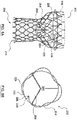
- FIG. 1A illustrates valve assembly 102 in a radially expanded fully deployed configuration.
- Valve assembly 102 includes a frame 104, a prosthetic valve 108, and a repositioning wire 120, as described above.
- Frame 104 is of a generally tubular configuration including a first end 104 and a second end 106, and defines a central passage 106 therethrough.
- Frame 104 is a support structure that comprises a number of wire members 110 arranged relative to each other to create open spaces 112.
- Prosthetic valve 108 is coupled to frame 104 and disposed within central passage 106 of frame 104.
- Valve assembly 102 further includes a first repositioning wire 120A and a second repositioning wire 120B.
- first repositioning wire 120A is disposed adjacent first end 114 (inflow end) of frame 104 and second repositioning wire 120B is disposed adjacent second end 116 (outflow end) of frame 104.
- FIGS. 1A-2B show two repositioning wires, more or fewer repositioning wires may be utilized.
- a single reposition wire may be utilized adjacent the first end, second end, or middle portion of frame 104.
- a third repositioning wire may be added between the first and second repositioning wires.
- first repositioning wire 120A includes a first end 122A coupled to frame 104.
- First repositioning wire 120A wraps around a circumference of frame 104 to a second end 124A, as shown in FIG. 1A .
- second repositioning wire 120B includes a first end 122B coupled to frame 104.
- Second repositioning wire 120B wraps around a circumference of frame 104 to a second end 124B, as shown in FIG. 1A .
- each of first and second repositioning wires 120A, 120B wraps around the circumference of frame 104 at least 75% of the circumference of frame 104 at the location of each respective repositioning wire.
- each repositioning wire 120A, 120B may be woven through open spaces 112 of frame 104, above some frame members 110 and below others.
- Each repositioning wire 120A, 120B is configured such that when respective second end 124A, 124B of each repositioning wire 120A, 120B is pulled, frame 104 of valve assembly 102 is compressed from the radially expanded fully deployed configuration to a radially compressed repositioning configuration, thereby also compressing valve assembly 102 from the radially expanded fully deployed configuration to the radially compressed repositioning configuration.
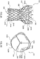
- valve assembly 102 has an outer diameter D e when in the radially expanded fully deployed configuration, as shown in FIGS. 1A-1B which is greater than an outer diameter D c when in the radially compressed repositioning configuration, as shown in FIGS. 2A-2B .
- Outer diameter D c may be in the range of 40% to 80% of outer diameter D e .
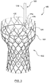
- FIG. 3 shows an embodiment of a valve assembly repositioning system 100 including valve assembly 102 and a snare device 130.
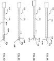
- Snare device 130 shown in more detail in FIGS. 4A-4D , is an elongated device including a shaft 170 configured for delivery through the vasculature, and a clasping mechanism 176 disposed at a distal end 174 of shaft 170 of snare device 130. More particularly, clasping mechanism 176 is user actuated from a location at a proximal end (not shown) of snare device 130. Clasping mechanism 176 is configured to grasp and hold second end 124B of repositioning wire 120B, as shown in FIG. 3 .
- snare device 130 could instead grasp repositioning wire 120A, or snare device 130 may include a plurality of clasping mechanisms, one for each repositioning wire, or a plurality of snare devices 130 could be used, one for each repositioning wire.
- Snare device 130 is further configured to pull repositioning wire 120B such that valve assembly 102 is compressed from the radially expanded fully deployed configuration to the radially compressed repositioning configuration. In the embodiment shown in FIGS.
- repositioning wire 120B is pulled by rotating snare device 130 in a direction R1 such that repositioning wire 120B wraps circumferentially around shaft 170 of snare device 130, as shown in FIGS. 4A-4D .
- snare device 130 is rotated in a direction (not shown) opposite direction R1.
- Snare device 130 is also configured to move valve assembly 102 longitudinally within the native vessel or valve when valve assembly 102 is in the radially compressed repositioning configuration.
- the user pushes or pulls snare device 130, respectively.
- moving snare device 130 distally moves valve assembly 102 distally (i.e., away from the clinician), and moving snare device 130 proximally moves valve assembly 102 proximally (i.e., towards the clinician).
- Clasping mechanism 176 shown in FIGS. 3-4D is shown including a pair of jaws 177A, 177B.
- any clasping mechanism suitable to grasp and hold a repositioning wire may be utilized.
- jaws 177A, 177B are displaceable towards and away from one another and are formed from a resilient material.
- jaws 177A, 177B are biased into a normally open configuration, as shown in FIG. 4B .
- shaft 170 is extended at least partially over clasping mechanism 176 to maintain jaws 177A, 177B in a closed configuration.
- shaft 170 When it is desired to open jaws 177A, 177B, shaft 170 is retracted proximally to expose jaws 177A, 177B such that their natural bias opens jaws 177A, 177B, as shown in FIG. 4B .
- shaft 170 With the repositioning wire 120B disposed between jaws 177A, 177B, shaft 170 is moved distally to force jaws 177A, 177B together, as shown in FIG. 4C .
- Snare device 130 may then be rotated in direction R1, as shown in FIG. 4D , to pull the repositioning wire by wrapping it around shaft 170, as explained above.
- Other clasping mechanisms may be utilized.
- the jaws may be opening and closed by a mechanical linkage extending proximally to a handle which is operated by the user.
- Other clasping mechanisms which do not necessarily include two jaws, may also be utilized.
- FIGS. 5A-7C illustrate schematically a valve assembly repositioning system 200 including a valve assembly 202 and a snare device 230 according to another embodiment hereof.
- Valve assembly repositioning system 200 is similar to valve assembly repositioning system 100 described above.
- valve assembly 202 is shown in FIGS. 5A-5B and includes a frame 204 and a prosthetic valve 208 as described above.
- Frame 204 and prosthetic valve 208 may be similar to frame 104 and prosthetic valve 108 describe above and the description in paragraphs [0040]-[0043] above, which are incorporated herein with respect to frame 204 and prosthetic valve 208.
- frame 204 includes a first end 214, a second end 216, and defines a central passage 206 therethrough.
- Frame 204 includes a number of wire members 210 arranged relative to each other to create open spaces 212.
- Prosthetic valve 208 is coupled to frame 204 and disposed within central passage of frame 204.
- valve assembly further includes a repositioning wire 220.
- Repositioning wire 220 includes a first end 222 coupled to frame 204. Repositioning wire 220 wraps around a circumference of frame 204 to a second end 224, as shown in FIGS. 5A-5B . With valve assembly 202 in the radially expanded fully deployed configuration, repositioning wire 220 wraps around the circumference of frame 204 at least 75% of the circumference of frame 204 at the location of repositioning wire 220. As previously described, repositioning wire 220 may be woven through open spaces 212 of frame 204, above some frame members 210 and below others.
- a lasso 226 is coupled to second end 224 of repositioning wire 220.
- Lasso 226 is of a generally circular shape creating a loop. Lasso 226 may be coupled to second end 224 by laser or ultrasonic welding, adhesives, or other methods suitable for the purposes disclosed herein.
- lasso 226 may be formed as an extension of repositioning wire 220 such that repositioning wire 220 forms a loop which is coupled to the remainder of repositioning wire 220 by a knot, laser or ultrasonic welding, adhesives, or other suitable connection methods.
- Repositioning wire 220 and lasso 226 may be made of the same materials described above for the repositioning wires.
- a single repositioning wire 220 is shown disposed around second end 216 of frame 204.
- more than one repositioning wire may be utilized.
- repositioning wire 220 is not limited to the location at the second end 216 of frame 204.
- FIGS. 7A-7E show an embodiment of snare device 230.
- Snare device 230 is an elongated device including a shaft 270 configured for delivery through the vasculature.
- a snare wire 275 including a snare mechanism 276 at a distal end 277 of snare wire 275 extends through a lumen 278 of shaft 270 and is slidable with respect to shaft 270.
- snare mechanism 276 may be a hook, as shown, but other configurations suitable to snaring lasso 226 may also be used.
- the position of snare mechanism 276 relative to shaft 270 is user selectable from a location at a proximal end (not shown) of snare device 23.
- Snare wire 275 and snare mechanism 276 may be constructed of materials such as, but not limited to stainless steel, Nitinol, nylon, polybutester, polypropylene, silk, and polyester or other materials suitable for the purposes described herein.
- snare device 230 may be delivered to a location of fully deployed valve assembly 202 with snare mechanism 276 disposed within lumen 278 of shaft 270, as shown in FIG. 7A .
- Snare device 230 may also be delivered with snare mechanism 276 distal of distal end 274 or snare wire may be delivered through lumen 278 after shaft 270 is delivered.
- snare wire 275 is extended distally relative to shaft 270 such that snare mechanism 276 is distal of distal end 274 of shaft 270, as shown in FIG. 7B .
- Snare mechanism 276 is then manipulated to snare lasso 226 of repositioning wire 220, as shown in FIG. 6 and 7C .
- snare wire 275 may be retracted proximally in direction L p to pull lasso 226 (and thus repositioning wire 220 coupled to lasso 226) towards shaft 270, as shown in FIG. 7D .
- valve assembly 202 is compressed from the radially expanded fully deployed configuration to the radially compressed repositioning configuration.
- Snare wire 275 may be retracted proximally until snare mechanism 276 and lasso 220 are disposed within lumen 278 of shaft 270, as shown in FIG. 7E .
- snare device 230 may be manipulated to move valve assembly 202 within the native vessel/valve. To move valve assembly 202 distally or proximally, the user pushes or pulls snare device 230, respectively.
- valve assembly 202 when snare device 230 has snared and pulled lasso 226 of repositioning wire 220, and valve assembly 202 is in the radially compressed repositioning configuration, moving snare device 230 distally moves valve assembly 202 distally, and moving snare device 230 proximally moves valve assembly 202 proximally.
- valve assembly 202 may include more than one repositioning wire.
- FIG. 8 shows valve assembly 202 including first and second repositioning wires 220A, 220B at first end 214 and second end 216 of frame 204, respectively.
- Valve assembly 202 shown in FIG. 8 is the same as the embodiment shown in FIGS. 5A-5B except for the additional repositioning wire.
- FIGS. 5A-5B shows valve assembly 202 including first and second repositioning wires 220A, 220B at first end 214 and second end 216 of frame 204, respectively.
- Valve assembly 202 shown in FIG. 8 is the same as the embodiment shown in FIGS. 5A-5B except for the additional repositioning wire.
- FIGS. 9 and 10A-10D show an embodiment of a snare device 330 which may be used in conjunction with valve assembly 202 including first and second repositioning wires 220A, 220B.
- Snare device 330 is an elongated device including a first snare 376 and a second snare 386.
- First snare 376 is disposed at a distal end 374 of a first shaft or wire 370.
- Second snare 386 is disposed at a distal end 384 of a second shaft 380.
- Second shaft 380 defines a lumen 388 through which first shaft 370 is slidably disposed.
- Snare device 330 may optionally include a third shaft 390 including a lumen 398.
- First and second shafts 370, 380 are slidable through third shaft 390.
- the position of first snare 376 relative to second snare 386 of snare device 330 is user adjustable by sliding first shaft 370 and second shaft 380 relative to each other.
- First snare 376 and second snare 386 are curved or sharply bent shapes suitable for catching, snagging, or snaring first lasso 226A and second lasso 226B, respectively. While FIGS. 9 and 10A-10D show first snare 376 and second snare 386 as a hook shape, this is not meant to limit the design and other shapes or constructions may be provided that are suitable for the purposes outlined herein.
- First and second snares 376, 386 may be constructed of materials such as, but not limited to stainless steel, Nitinol, nylon, polybutester, polypropylene, silk, and polyester or other materials suitable for the purposes described herein.
- Snare device 330 may be advanced to a location of a fully deployed valve assembly in the configuration shown in FIG. 10A , with first and second shafts 370, 380 and first and second snares 376, 386 disposed within lumen 398 of third shaft 390. However, snare device 330 may be advanced to the location of a fully deployed valve assembly in other configurations. When at the desired location, first snare 376 and second snare 386 are exposed, for example, by retracting third shaft 390 or advancing first and second shafts 370, 380, as shown in FIG. 10B .
- First snare 376 and second snare 386 are manipulated such that first snare 376 is placed through first lasso 226A of repositioning wire 220A and second snare 386 is placed through second lasso 226B of repositioning wire 220B, as shown in FIG. 10C .
- first and second shafts 376, 386 may be moved in opposite directions, as indication by arrows L d and L p , respectively, in FIG. 10D .
- first snare 376 is move distally and second snare 386 is moved proximally.
- Moving first snare 376 and second snare 386 in opposite directions causes first lasso 226A and second lasso 226B to be pulled, thereby causing first repositioning wire 220A and second repositioning wire 220B to be pulled, respectively.
- Pulling of first repositioning wire 220A and second repositioning wire 220B radially compresses valve assembly 202 from the radially expanded fully deployed configuration to the radially compressed repositioning configuration, as explained above.
- snare device 330 may be manipulated to move valve assembly 202 within the native vessel/valve. To move valve assembly 202 distally or proximally within the native valve, the user moves snare device 330 distally or proximally, respectively.
- valve assembly 202 is in the radially compressed repositioning configuration, moving snare device 330 distally moves valve assembly 202 distally, and moving snare device 330 proximally moves valve assembly 202 proximally.
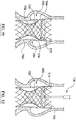
- FIGS. 11-16 An example, not forming part of the invention, of a method of repositioning a fully deployed valve assembly in a native valve is schematically represented in FIGS. 11-16 .
- a valve assembly 102 is fully deployed adjacent a native valve 700 at a first location.
- Valve assembly 102 is in a radially expanded fully deployed configuration and is thus disconnected from a delivery device.
- valve assembly 102 includes a frame 104, a repositioning wire 120, and a prosthetic valve 108.
- valve assembly 102 may not be performing as desired, and repositioning of valve assembly 102 is desired to improve valve performance. For example, and not by way of limitation, it may be determined that valve assembly 102 is "too deep" into the annulus 702 such that it may interfere with the left ventricular outflow tract (LVOT) or form gaps between frame 104 and annulus 702 causing paravalvular leakage. In another example, valve assembly 102 may not be deep enough in annulus such that frame 104 is not properly secured against annulus 702, which may also cause paravalvular leakage.
- LVOT left ventricular outflow tract
- Snare device 130 is advanced through the patient's vasculature and is positioned adjacent valve assembly 102.
- Clasping mechanism 176 of snare device 130 is manipulated by the treating clinician to grasp a second end 124 of repositioning wire 120, as shown in FIG. 12 .
- Snare device 130 is rotated in a direction R1 by the treating clinician, thereby pulling repositioning wire 120 as it wraps circumferentially around shaft 170 of snare device 130.
- the pulling of repositioning wire 120 compresses valve assembly 102 from the radially expanded fully deployed configuration to the radially compressed repositioning configuration, as shown in FIG. 13 .
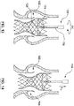
- Snare device 130 may then be moved proximally or distally to reposition valve assembly 102 from the first location of FIG. 11 to a second location adjacent native valve 700.
- FIG. 14 shows snare device 130 and valve assembly 102 being moved proximally in a direction L p to the second location as determined by the treating clinician. However, valve assembly 102 may be moved distally.
- Snare device 130 is rotated in a direction R2 opposite direction R1 by the treating clinician, thereby releasing the pulling force on repositioning wire 120 as repositioning wire 120 unwraps circumferentially from shaft 170 of snare device 130.
- frame 104 of valve assembly 102 self-expands from the radially compressed repositioning configuration to the radially expanded fully deployed configuration at the second location, as shown in FIG. 15 .
- valve assembly 102 Once valve assembly 102 is in its radially expanded fully deployed configuration at the second location, snare device 130 may be withdrawn from the patient. Valve assembly 102 remains fully deployed at the repositioned second location adjacent native valve 700, as shown in FIG. 16 .
- a similar method may be used for a valve assembly 102 including a plurality of repositioning wires 120.
- a snare device may be used for each repositioning wire.
- a snare device may include multiple clasping mechanisms, one for each of the plurality of repositioning wires.
- a similar method may be used to reposition valve assembly 202 of FIGS. 5A-5B utilizing the snare device of FIGS. 7A-7E .
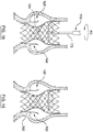
- FIGS. 17-22 schematically show a method, not forming part of the invention, of repositioning a fully deployed valve assembly 202.
- a valve assembly 202 is fully deployed adjacent a native valve 700 at a first location.
- Valve assembly 202 is in a radially expanded fully deployed configuration and thus is disconnected from a delivery device.
- valve assembly 202 includes a frame 204, first and second repositioning wires 220A, 220B, and a prosthetic valve 208. As determined by the treating clinician, valve assembly 202 may not be performing as desired, and repositioning of valve assembly 202 is desired to improve valve performance. For example, and not by way of limitation, it may be determined that valve assembly 202 is "too deep" into the annulus 702 such that it may interfere with the left ventricular outflow tract (LVOT) or form gaps between frame 204 and annulus 702 causing paravalvular leakage. In another example, valve assembly 202 may not be deep enough in annulus such that frame 204 is not properly secured against annulus 702, which may also cause paravalvular leakage.
- LVOT left ventricular outflow tract
- Snare device 330 is advanced through the patient's and is positioned within valve assembly 202, as shown in FIG. 18 .
- First snare 376 is manipulated by the treating clinician to snare first lasso 226A of first repositioning wire 220A and second snare 386 is manipulated by the treating clinician to snare second lasso 226B of second repositioning wire 220B, as shown in FIG. 18 .
- snare device 330 is actuated by the treating clinician such that first snare 376 and second snare 386 are moved apart from each other.
- first repositioning wire 220A and second repositioning wire 220B to be pulled in directions L d and L p , respectively, thereby compressing valve assembly 202 from the radially expanded fully deployed configuration to a radially compressed repositioning configuration, as shown in FIG. 19 .
- Snare device 330 may then be moved proximally or distally to reposition valve assembly 202 from the first location of FIG. 17 to a second location adjacent the native valve 700.
- FIG. 20 shows snare device 330 and valve assembly 202 being moved proximally in a direction L p to the second location as determined by the treating clinician.
- valve assembly 202 may instead be moved distally.
- valve assembly 202 When valve assembly 202 is positioned at the repositioned second location, the treating clinician may move first snare 376 and second snare 386 back toward each other such that the pulling force on first repositioning wire 220A and second repositioning wire 220B is released. As the pulling force on repositioning wires 220A and 220B is released, valve assembly 202 self-expands from the radially compressed repositioning configuration to the radially expanded fully deployed configuration at the second location, as shown in FIG. 21 .
- valve assembly 202 Once valve assembly 202 is and in its radially expanded fully deployed configuration at the second location, snare device 330 may be withdrawn from the patient. Valve assembly 202 remains fully deployed at the repositioned second location adjacent native valve 700, as shown in FIG. 22 .
Landscapes
- Health & Medical Sciences (AREA)
- Cardiology (AREA)
- Engineering & Computer Science (AREA)
- Biomedical Technology (AREA)
- Oral & Maxillofacial Surgery (AREA)
- Transplantation (AREA)
- Heart & Thoracic Surgery (AREA)
- Vascular Medicine (AREA)
- Life Sciences & Earth Sciences (AREA)
- Animal Behavior & Ethology (AREA)
- General Health & Medical Sciences (AREA)
- Public Health (AREA)
- Veterinary Medicine (AREA)
- Mechanical Engineering (AREA)
- Prostheses (AREA)
Description
- The present disclosure relates to devices, systems, and methods for repositioning a fully deployed valve assembly. The methods described herein do not form part of the invention.
- Heart valves are sometimes damaged by disease or by aging, resulting in problems with the proper functioning of the valve. Heart valve replacement has become a routine surgical procedure for patients suffering from valve dysfunctions. Traditional open surgery inflicts significant patient trauma and discomfort, requires extensive recuperation times, and may result in life-threatening complications.
- To address these concerns, minimally invasive techniques, such as transcatheter valve implantation techniques, have been developed to deliver and deploy valve prostheses. In such methods, the valve prosthesis or valve assembly generally includes a frame and a prosthetic valve, and is radially compressed for delivery in a catheter and then advanced to the location of a native valve, where the valve assembly is deployed by radial expansion. The catheter may be advanced, for example through an opening in the native vasculature remote from the native valve, such as the femoral artery, and advanced through the vasculature to the native valve. In other techniques, the catheter is advanced through an opening in the heart to the location of the native valve, such as transapical or transatrially, or through an opening in the ascending aorta.
- In some patients, the valve assembly may not perform as desired following implantation. For example, due to the position of the valve assembly, the valve assembly may not properly seal with the native valve and/or walls surrounding the native valve. This may result in paravalvular leakage (PVL), and other post surgical complications. Further, the valve assembly may not function properly due to the position of the valve assembly at the native valve. However, once a valve assembly is fully deployed and released from the delivery device, there is no easy way to reposition to the valve assembly to a new location.
US 2007/0100427 A1 describes a device for treating a blood vessel and associated treatment kit.US 2008/0039934 A1US 2014/0249564 A1 describes methods of repositioning a transcatheter heart valve after full deployment. - Accordingly, there is a need for a valve assembly, system and method of repositioning a fully deployed valve assembly.
- Embodiments hereof relate to a valve assembly including a frame, a prosthetic valve, and a repositioning wire. The frame defines a central passage. The prosthetic valve is coupled to the frame and disposed in the central passage of the frame. The repositioning wire is coupled to the frame. The repositioning wire is configured such that with the valve assembly in a radially expanded fully deployed configuration, pulling the repositioning wire radially compresses the valve assembly from the radially expanded fully deployed configuration to a radially compressed repositioning configuration, as defined by
claim 1. - Embodiments hereof also relate to a valve assembly repositioning system for repositioning a valve assembly that is in a radially expanded fully deployed configuration. The valve assembly repositioning system includes the valve assembly and a snare device. The valve assembly includes a frame that defines a central passage, a prosthetic valve coupled to the frame, and a repositioning wire coupled to the frame. The snare device is configured to snare and pull the repositioning wire to radially compress the valve assembly from the radially expanded fully deployed configuration to a radially compressed repositioning configuration. The snare device is also configured to move the valve assembly when the valve assembly is in the radially compressed repositioning configuration.
- Examples that do not form part of the invention hereof also relate to a method of repositioning a valve assembly having a frame, a prosthetic valve coupled to the frame, and a repositioning wire coupled to the frame. The method includes advancing a snare device to a location of the valve assembly with the valve assembly in a radially expanded fully deployed configuration at a first location adjacent a native valve. The snare device snares the repositioning wire. The snare device is manipulated such that the repositioning wire is pulled to radially compress the valve assembly from the radially expanded fully deployed configuration to a radially compressed repositioning configuration. The valve assembly is moved from the first location to a second location adjacent the native valve by manipulation of the snare device. The repositioning wire is released from the snare device and the valve assembly radially expands from the radially compressed repositioning configuration back to the radially expanded fully deployed configuration.
-
-
FIG. 1A is a side perspective schematic illustration of a valve assembly according to an embodiment hereof with the valve assembly in a radially expanded fully deployed configuration. -
FIG. 1B an end view schematic illustration of the valve assembly ofFIG. 1A . -
FIG. 2A is a side view schematic illustration of the valve assembly ofFIG. 1A in a radially compressed repositioning configuration. -
FIG. 2B is an end view schematic illustration of the valve assembly ofFIG. 1A in a radially compressed repositioning configuration. -
FIG. 3 is a side perspective schematic illustration of a valve assembly repositioning system according to an embodiment hereof, with the valve assembly ofFIG. 1A . -
FIGS. 4A-4D are a series of side illustrations of a snare device grasping and pulling a repositioning wire. -
FIG. 5A is a side perspective schematic illustration of a valve assembly according to another embodiment hereof, wherein the repositioning wire includes a lasso. -
FIG. 5B is an end view perspective schematic illustration of the valve assembly ofFIG. 5A . -
FIG. 6 is a side perspective schematic illustration of a valve assembly repositioning system according to an embodiment hereof, with the valve assembly ofFIG. 5A . -
FIGS. 7A-7E are a series of close up side illustrations of snare device snaring and pulling the lasso of the repositioning wire. -
FIG. 8A is a side perspective schematic illustration of the valve assembly ofFIG. 5A , wherein the valve assembly includes a plurality of repositioning wires with lassos. -
FIG. 8B is an end view perspective schematic illustration of the valve assembly ofFIG. 8A . -
FIG. 9 is a side perspective schematic illustration of a valve assembly repositioning system according to an embodiment hereof, with the valve assembly ofFIG. 8 . -
FIGS. 10A-10D are a series of side schematic illustrations of a snare device snaring and pulling the lassos of the repositioning wires of the valve assembly ofFIG. 8 . -
FIGS. 11-16 are schematic illustrations of an example not forming part of the invention of a method of repositioning a fully deployed valve assembly. -
FIG. 11 is a schematic illustration of the valve assembly ofFIG. 1A in a radially expanded fully deployed configuration and disposed at a first location adjacent a native valve. -
FIG. 12 is a schematic illustration a step in the method, not forming part of the invention, of repositioning the valve assembly, wherein the snare device has grasped the repositioning wire. -
FIG. 13 is a schematic illustration of a step in the method, not forming part of the invention, of repositioning the valve assembly, wherein the snare device is pulling the repositioning wire and the valve assembly is collapsing to the radially collapsed repositioning configuration. -
FIG. 14 is a schematic illustration of a step in the method, not forming part of the invention, of repositioning the valve assembly, wherein the valve assembly is in the radially collapsed repositioning configuration and is being moved to a second location adjacent the native valve. -
FIG. 15 is a schematic illustration of a step in the method, not forming part of the invention, of repositioning the valve assembly, wherein the snare device is releasing the repositioning wire and the valve assembly is expanding to the radially expanded fully deployed configuration at the second location. -
FIG. 16 is a schematic illustration of a step in the method, not forming part of the invention, of repositioning the valve assembly, wherein the snare device has released the valve assembly such that the valve assembly is in the radially expanded fully deployed configuration at the second location. -
FIGS. 17-22 are schematic illustrations of another example not forming part of the invention of a method of repositioning a fully deployed valve assembly. -
FIG. 17 is a schematic illustration of the valve assembly ofFIG. 8A in a radially expanded fully deployed configuration and disposed at a first location adjacent a native valve. -
FIG. 18 is a schematic illustration of a step in the method, not forming part of the invention, of repositioning the valve assembly, wherein the snare device has snared the lassos of the repositioning wires. -
FIG. 19 is a schematic illustration of a step in the method, not forming part of the invention, of repositioning the valve assembly, wherein the snare device is pulling the repositioning wires to collapse the valve assembly to the radially collapsed repositioning configuration. -
FIG. 20 is a schematic illustration of a step in the method, not forming part of the invention, of repositioning the valve assembly, wherein the valve assembly is in the radially collapsed repositioning configuration and is being moved to a second location adjacent the native valve. -
FIG. 21 is a schematic illustration of a step in the method, not forming part of the invention, of repositioning the valve assembly, wherein the snare device is releasing the repositioning wire and the valve assembly is expanding to the radially expanded fully deployed configuration at the second location. -
FIG. 22 is a schematic illustration of a step in the method, not forming part of the invention, of repositioning the valve assembly, wherein the snare device has released the valve assembly such that the valve assembly is in the radially expanded fully deployed configuration at the second location. - Specific embodiments of the present invention are now described with reference to the figures, wherein like reference numbers indicate identical or functionally similar elements. The terms "distal" and "proximal", when used in the following description to refer to a catheter or delivery device, are with respect to a position or direction relative to the treating clinician. Thus, "distal" and "distally" refer to positions distant from, or in a direction away from, the clinician and "proximal" and "proximally" refer to positions near, or in a direction toward, the clinician. When the terms "distal" and "proximal" are used in the following description to refer to a device implanted into a native artery, such as a valve assembly, they are used with reference to the direction of blood flow from the heart. Thus "distal" and "distally" refer to positions in a downstream direction with respect to the direction of blood flow and "proximal" and "proximally" refer to positions in an upstream direction with respect to the direction of blood flow.
- The following detailed description is merely exemplary in nature and is not intended to limit the invention or the application and uses of the invention. Although the description of the invention is in the context of a transcatheter aortic valve repositioning system, the invention may also be used in other body passageways where it is deemed useful. Furthermore, there is no intention to be bound by any expressed or implied theory presented in the preceding technical field, background, brief summary, or the following detailed description.
- As used herein the terms "fully deployed", "fully deployed configuration", and "radially expanded fully deployed configuration" mean that the device, such as a valve assembly or frame, that is described using these terms has been deployed at a site within the body, has been radially expanded (such as by balloon expansion or selfexpansion), and has been released from the delivery device. Thus, for example, a valve assembly wherein a portion of the valve assembly has been radially expanded but a portion of the valve assembly is either not radially expanded or is still attached to the delivery device, is not considered "fully deployed", in a "fully deployed configuration", or in a "radially expanded fully deployed configuration".
- The valve assembly of the present invention includes a frame, a prosthetic valve, and at least one repositioning wire. The valve assembly has a radially expanded fully deployed configuration that is collapsible to a radially compressed repositioning configuration for repositioning the valve assembly after the valve assembly has been fully deployed adjacent a native valve. The valve assembly also has a radially compressed delivery configuration (not shown), which is a smaller diameter than the radially compressed repositioning configuration.
- The frame of the valve assembly is a generally tubular configuration having a proximal end, a distal end, and a lumen therebetween. The frame is a stent structure as is known in the art, as described in more detail below. The frame may be self expanding or may be balloon expandable. The frame may comprise a number of strut or wire portions arranged relative to each other to provide a desired compressibility, strength, and leaflet attachment zone(s). The frame is a generally tubular support structure, and leaflets are secured to the frame to provide a stented prosthetic valve.
- The prosthetic valve of the valve assembly is attached to the frame. The prosthetic valve may also include a skirt affixed to the frame. The prosthetic valve may include a plurality of prosthetic valve leaflets, which may be attached along their bases to the skirt, for example, using sutures or a suitable biocompatible adhesive, or may be attached to the skirt or frame in other ways known to those skilled in the art. Adjoining pairs of leaflets may be attached to one another at their lateral ends to form commissures with free edges of the leaflets forming coaptation edges that meet in an area of coaptation. The prosthetic valve leaflets may be formed from a variety of materials, such as autologous tissue, xenograph material, or synthetics as are known in the art. The leaflets may be provided as a homogenous, biological valve structure, such as a porcine, bovine, or equine valve. Alternatively, the leaflets can be provided independent of one another (e.g., bovine or equine pericardial leaflets) and subsequently assembled to the support structure of the the frame. In another alternative, the frame and leaflets may be fabricated at the same time, such as may be accomplished using high strength nano-manufactured NiTi films of the type produced at Advanced Bio Prosthetic Surfaces Ltd. (ABPS) of San Antonio, Tex., for example.
- The frame and prosthetic valve of the valve assembly may be similar to the Medtronic CoreValve® transcatheter aortic valve replacement valve prosthesis and as described in
U.S. Patent Application Publication No. 2011/0172765 to Nguyen al. However, those skilled in the art would recognize that any suitable valve prosthesis may be used in the present embodiment as the frame and prosthetic valve of the valve assembly. For example, and not by way of limitation, the combination of a frame and prosthetic valve of the valve assembly may assume a variety of other configurations that differ from those shown and described, including any known prosthetic heart valve design. In various embodiments, the frame and the prosthetic valve may utilize certain features of known expandable prosthetic heart valve configurations, whether balloon expandable, selfexpanding, or unfurling (as described, for example, inU.S. Pat. Nos. 3,671,979 ;4,056,854 ;4,994,077 ;5,332,402 ;5,370,685 ;5,397,351 ;5,554,185 ;5,855,601 ; and6,168,614 ;U.S. Patent Application Publication No. 2004/0034411 ; Bonhoeffer P., et al., "Percutaneous Insertion of the Pulmonary Valve", Pediatric Cardiology, 2002; 39:1664-1669; Anderson H R, et al., "Transluminal Implantation of Artificial Heart Valves", EUR Heart J., 1992; 13:704-708; Anderson, J. R., et al., "Transluminal Catheter Implantation of New Expandable Artificial Cardiac Valve", EUR Heart J., 1990, 11: (Suppl) 224a; Hilbert S. L., "Evaluation of Explanted Polyurethane Trileaflet Cardiac Valve Prosthesis", J Thorac Cardiovascular Surgery, 1989; 94:419-29; Block P C, "Clinical and Hemodynamic Follow-Up After Percutaneous Aortic Valvuloplasty in the Elderly", The American Journal of Cardiology, Vol. 62, Oct. 1, 1998; Boudjemline, Y., "Steps Toward Percutaneous Aortic Valve Replacement", Circulation, 2002; 105:775-558; Bonhoeffer, P., "Transcatheter Implantation of a Bovine Valve in Pulmonary Position, a Lamb Study", Circulation, 2000: 102:813-816; Boudjemline, Y., "Percutaneous Implantation of a Valve in the Descending Aorta In Lambs", EUR Heart J, 2002; 23:1045-1049; Kulkinski, D., "Future Horizons in Surgical Aortic Valve Replacement: Lessons Learned During the Early Stages of Developing a Transluminal Implantation Technique", ASAIO J, 2004;). - The valve assembly of the present invention adds at least one repositioning wire. The term "wire" as used herein means an elongated element or filament or group of elongated elements or filaments and is not limited to a particular crosssectional shape or material, unless so specified. The repositioning wire of the present disclosure includes a first end coupled to the frame. The repositioning wire extends from the first end around a circumference of the frame to a second end disposed opposite the first end. The first end of the repositioning wire may be coupled to the frame of the valve assembly by methods such as, but not limited to laser or ultrasonic welding, adhesives, tying, or other methods suitable for the purposes disclosed herein. The repositioning wire wraps around at least a portion of the circumference of the valve assembly. In an embodiment, with the valve assembly is in the radially expanded fully deployed configuration, the repositioning wire wraps around at least 75% of the circumference of the frame at the location of the repositioning wire. The repositioning wire may be woven through the open spaces of the frame of the valve assembly, above some frame members and below others. The repositioning wire is configured such that when the second end of the repositioning wire is pulled, the valve assembly is compressed from the radially expanded fully deployed configuration to the radially compressed repositioning configuration. The repositioning wire may be constructed of materials such as, but not limited to stainless steel, Nitinol, nylon, polybutester, polypropylene, silk, and polyester or other materials suitable for the purposes described herein.
- The present disclosure also discloses a valve assembly repositioning system, which includes a valve assembly, as described above, and a snare device. The snare device is an elongate member configured to snare and to pull the repositioning wire of the valve assembly such that the valve assembly is compressed from the radially expanded fully deployed configuration to the radially compressed repositioning configuration. The snare device is also configured to move the valve assembly from a first location adjacent a native valve to a second location adjacent a native valve when the valve assembly is in the radially compressed repositioning configuration.
- With the above understanding in mind, an embodiment of a
valve assembly 102 according to the present disclosure is shown inFIGS. 1A-2B .FIG. 1A illustratesvalve assembly 102 in a radially expanded fully deployed configuration.Valve assembly 102 includes aframe 104, aprosthetic valve 108, and arepositioning wire 120, as described above. -
Frame 104 is of a generally tubular configuration including afirst end 104 and asecond end 106, and defines acentral passage 106 therethrough.Frame 104 is a support structure that comprises a number ofwire members 110 arranged relative to each other to createopen spaces 112.Prosthetic valve 108 is coupled to frame 104 and disposed withincentral passage 106 offrame 104. -
Valve assembly 102 further includes afirst repositioning wire 120A and asecond repositioning wire 120B. In the embodiment shown,first repositioning wire 120A is disposed adjacent first end 114 (inflow end) offrame 104 andsecond repositioning wire 120B is disposed adjacent second end 116 (outflow end) offrame 104. AlthoughFIGS. 1A-2B show two repositioning wires, more or fewer repositioning wires may be utilized. For example, and not by way of limitation, a single reposition wire may be utilized adjacent the first end, second end, or middle portion offrame 104. Alternatively, and also not by way of limitation, a third repositioning wire may be added between the first and second repositioning wires. As explained above,first repositioning wire 120A includes afirst end 122A coupled toframe 104.First repositioning wire 120A wraps around a circumference offrame 104 to asecond end 124A, as shown inFIG. 1A . Similarly,second repositioning wire 120B includes afirst end 122B coupled toframe 104.Second repositioning wire 120B wraps around a circumference offrame 104 to asecond end 124B, as shown inFIG. 1A . In an embodiment, withvalve assembly 102 in the radially expanded fully deployed configuration, each of first andsecond repositioning wires frame 104 at least 75% of the circumference offrame 104 at the location of each respective repositioning wire. As previously described, eachrepositioning wire open spaces 112 offrame 104, above someframe members 110 and below others. - Each
repositioning wire second end repositioning wire frame 104 ofvalve assembly 102 is compressed from the radially expanded fully deployed configuration to a radially compressed repositioning configuration, thereby also compressingvalve assembly 102 from the radially expanded fully deployed configuration to the radially compressed repositioning configuration. As shown inFIGS. 1A-2B ,valve assembly 102 has an outer diameter De when in the radially expanded fully deployed configuration, as shown inFIGS. 1A-1B which is greater than an outer diameter Dc when in the radially compressed repositioning configuration, as shown inFIGS. 2A-2B . Outer diameter Dc may be in the range of 40% to 80% of outer diameter De. -
FIG. 3 shows an embodiment of a valveassembly repositioning system 100 includingvalve assembly 102 and asnare device 130.Snare device 130, shown in more detail inFIGS. 4A-4D , is an elongated device including ashaft 170 configured for delivery through the vasculature, and aclasping mechanism 176 disposed at adistal end 174 ofshaft 170 ofsnare device 130. More particularly, claspingmechanism 176 is user actuated from a location at a proximal end (not shown) ofsnare device 130. Claspingmechanism 176 is configured to grasp and holdsecond end 124B ofrepositioning wire 120B, as shown inFIG. 3 . Althoughsnare device 130 inFIG. 3 is shown graspingrepositioning wire 120B,snare device 130 could instead grasp repositioningwire 120A, orsnare device 130 may include a plurality of clasping mechanisms, one for each repositioning wire, or a plurality ofsnare devices 130 could be used, one for each repositioning wire.Snare device 130 is further configured to pullrepositioning wire 120B such thatvalve assembly 102 is compressed from the radially expanded fully deployed configuration to the radially compressed repositioning configuration. In the embodiment shown inFIGS. 3 and4A-4D ,repositioning wire 120B is pulled by rotatingsnare device 130 in a direction R1 such thatrepositioning wire 120B wraps circumferentially aroundshaft 170 ofsnare device 130, as shown inFIGS. 4A-4D . To releaserepositioning wire 120B,snare device 130 is rotated in a direction (not shown) opposite direction R1. -
Snare device 130 is also configured to movevalve assembly 102 longitudinally within the native vessel or valve whenvalve assembly 102 is in the radially compressed repositioning configuration. To movevalve assembly 102 distally or proximally, the user pushes or pullssnare device 130, respectively. Stated another way, whensnare device 130 has grasped and pulledrepositioning wire 120 andvalve assembly 102 is in the radially compressed repositioning configuration, movingsnare device 130 distally movesvalve assembly 102 distally (i.e., away from the clinician), and movingsnare device 130 proximally movesvalve assembly 102 proximally (i.e., towards the clinician). - Clasping
mechanism 176 shown inFIGS. 3-4D is shown including a pair ofjaws 177A, 177B. However, any clasping mechanism suitable to grasp and hold a repositioning wire may be utilized. In one embodiment,jaws 177A, 177B are displaceable towards and away from one another and are formed from a resilient material. In an embodiment,jaws 177A, 177B are biased into a normally open configuration, as shown inFIG. 4B . For delivery to the location ofvalve assembly 102,shaft 170 is extended at least partially overclasping mechanism 176 to maintainjaws 177A, 177B in a closed configuration. When it is desired to openjaws 177A, 177B,shaft 170 is retracted proximally to exposejaws 177A, 177B such that their natural bias opensjaws 177A, 177B, as shown inFIG. 4B . With therepositioning wire 120B disposed betweenjaws 177A, 177B,shaft 170 is moved distally to forcejaws 177A, 177B together, as shown inFIG. 4C .Snare device 130 may then be rotated in direction R1, as shown inFIG. 4D , to pull the repositioning wire by wrapping it aroundshaft 170, as explained above. Other clasping mechanisms may be utilized. For example, and not by way of limitation, the jaws may be opening and closed by a mechanical linkage extending proximally to a handle which is operated by the user. Other clasping mechanisms which do not necessarily include two jaws, may also be utilized. -
FIGS. 5A-7C illustrate schematically a valveassembly repositioning system 200 including avalve assembly 202 and asnare device 230 according to another embodiment hereof. Valveassembly repositioning system 200 is similar to valveassembly repositioning system 100 described above. In particular,valve assembly 202 is shown inFIGS. 5A-5B and includes aframe 204 and aprosthetic valve 208 as described above.Frame 204 andprosthetic valve 208 may be similar toframe 104 andprosthetic valve 108 describe above and the description in paragraphs [0040]-[0043] above, which are incorporated herein with respect to frame 204 andprosthetic valve 208. Thus, as described above,frame 204 includes afirst end 214, asecond end 216, and defines acentral passage 206 therethrough.Frame 204 includes a number of wire members 210 arranged relative to each other to create open spaces 212.Prosthetic valve 208 is coupled to frame 204 and disposed within central passage offrame 204. - Similar to the embodiments described above, valve assembly further includes a
repositioning wire 220.Repositioning wire 220 includes afirst end 222 coupled toframe 204.Repositioning wire 220 wraps around a circumference offrame 204 to asecond end 224, as shown inFIGS. 5A-5B . Withvalve assembly 202 in the radially expanded fully deployed configuration,repositioning wire 220 wraps around the circumference offrame 204 at least 75% of the circumference offrame 204 at the location of repositioningwire 220. As previously described,repositioning wire 220 may be woven through open spaces 212 offrame 204, above some frame members 210 and below others. - In the embodiment shown in of
FIGS. 5A-7C , alasso 226 is coupled tosecond end 224 ofrepositioning wire 220.Lasso 226 is of a generally circular shape creating a loop.Lasso 226 may be coupled tosecond end 224 by laser or ultrasonic welding, adhesives, or other methods suitable for the purposes disclosed herein. Alternatively, lasso 226 may be formed as an extension ofrepositioning wire 220 such thatrepositioning wire 220 forms a loop which is coupled to the remainder ofrepositioning wire 220 by a knot, laser or ultrasonic welding, adhesives, or other suitable connection methods.Repositioning wire 220 and lasso 226 may be made of the same materials described above for the repositioning wires. - In the embodiment of
FIGS. 5A-5B and6 , asingle repositioning wire 220 is shown disposed aroundsecond end 216 offrame 204. However, as described above, more than one repositioning wire may be utilized. Further,repositioning wire 220 is not limited to the location at thesecond end 216 offrame 204. -
FIGS. 7A-7E show an embodiment ofsnare device 230.Snare device 230 is an elongated device including ashaft 270 configured for delivery through the vasculature. Asnare wire 275 including asnare mechanism 276 at adistal end 277 ofsnare wire 275 extends through alumen 278 ofshaft 270 and is slidable with respect toshaft 270. In an embodiment,snare mechanism 276 may be a hook, as shown, but other configurations suitable to snaringlasso 226 may also be used. In an embodiment, the position ofsnare mechanism 276 relative toshaft 270 is user selectable from a location at a proximal end (not shown) of snare device 23.Snare wire 275 andsnare mechanism 276 may be constructed of materials such as, but not limited to stainless steel, Nitinol, nylon, polybutester, polypropylene, silk, and polyester or other materials suitable for the purposes described herein. - In an embodiment shown in
FIGS. 7A-7E ,snare device 230 may be delivered to a location of fully deployedvalve assembly 202 withsnare mechanism 276 disposed withinlumen 278 ofshaft 270, as shown inFIG. 7A .Snare device 230 may also be delivered withsnare mechanism 276 distal ofdistal end 274 or snare wire may be delivered throughlumen 278 aftershaft 270 is delivered. When at the desired location,snare wire 275 is extended distally relative toshaft 270 such thatsnare mechanism 276 is distal ofdistal end 274 ofshaft 270, as shown inFIG. 7B .Snare mechanism 276 is then manipulated to snarelasso 226 ofrepositioning wire 220, as shown inFIG. 6 and7C . Withsnare mechanism 276 engaged withlasso 226,snare wire 275 may be retracted proximally in direction Lp to pull lasso 226 (and thus repositioningwire 220 coupled to lasso 226) towardsshaft 270, as shown inFIG. 7D . Aslasso 226 andrepositioning wire 220 are pulled,valve assembly 202 is compressed from the radially expanded fully deployed configuration to the radially compressed repositioning configuration.Snare wire 275 may be retracted proximally untilsnare mechanism 276 and lasso 220 are disposed withinlumen 278 ofshaft 270, as shown inFIG. 7E . - With
snare mechanism 276 engaged withlasso 226 andrepositioning wire 220 pulled such thatvalve assembly 202 is in the radially compressed repositioning configuration,snare device 230 may be manipulated to movevalve assembly 202 within the native vessel/valve. To movevalve assembly 202 distally or proximally, the user pushes or pullssnare device 230, respectively. Stated another way, whensnare device 230 has snared and pulledlasso 226 ofrepositioning wire 220, andvalve assembly 202 is in the radially compressed repositioning configuration, movingsnare device 230 distally movesvalve assembly 202 distally, and movingsnare device 230 proximally movesvalve assembly 202 proximally. - As noted above,
valve assembly 202 may include more than one repositioning wire.FIG. 8 showsvalve assembly 202 including first andsecond repositioning wires first end 214 andsecond end 216 offrame 204, respectively.Valve assembly 202 shown inFIG. 8 is the same as the embodiment shown inFIGS. 5A-5B except for the additional repositioning wire. Thus, details of the valve assembly will not be repeated with respect to this embodiment, but the details described above with respect to other embodiments are incorporated herein. -
FIGS. 9 and10A-10D show an embodiment of asnare device 330 which may be used in conjunction withvalve assembly 202 including first andsecond repositioning wires Snare device 330 is an elongated device including afirst snare 376 and asecond snare 386.First snare 376 is disposed at adistal end 374 of a first shaft orwire 370.Second snare 386 is disposed at adistal end 384 of asecond shaft 380.Second shaft 380 defines alumen 388 through whichfirst shaft 370 is slidably disposed.Snare device 330 may optionally include athird shaft 390 including alumen 398. First andsecond shafts third shaft 390. The position offirst snare 376 relative tosecond snare 386 ofsnare device 330 is user adjustable by slidingfirst shaft 370 andsecond shaft 380 relative to each other.First snare 376 andsecond snare 386 are curved or sharply bent shapes suitable for catching, snagging, or snaringfirst lasso 226A andsecond lasso 226B, respectively. WhileFIGS. 9 and10A-10D showfirst snare 376 andsecond snare 386 as a hook shape, this is not meant to limit the design and other shapes or constructions may be provided that are suitable for the purposes outlined herein. First andsecond snares -
Snare device 330 may be advanced to a location of a fully deployed valve assembly in the configuration shown inFIG. 10A , with first andsecond shafts second snares lumen 398 ofthird shaft 390. However,snare device 330 may be advanced to the location of a fully deployed valve assembly in other configurations. When at the desired location,first snare 376 andsecond snare 386 are exposed, for example, by retractingthird shaft 390 or advancing first andsecond shafts FIG. 10B .First snare 376 andsecond snare 386 are manipulated such thatfirst snare 376 is placed throughfirst lasso 226A ofrepositioning wire 220A andsecond snare 386 is placed throughsecond lasso 226B ofrepositioning wire 220B, as shown inFIG. 10C . - With
first snare 376 engaged withfirst lasso 226A andsecond snare 386 engaged withsecond lasso 226B, first andsecond shafts FIG. 10D . In the embodiment shown,first snare 376 is move distally andsecond snare 386 is moved proximally. Movingfirst snare 376 andsecond snare 386 in opposite directions causesfirst lasso 226A andsecond lasso 226B to be pulled, thereby causingfirst repositioning wire 220A andsecond repositioning wire 220B to be pulled, respectively. Pulling offirst repositioning wire 220A andsecond repositioning wire 220B radially compressesvalve assembly 202 from the radially expanded fully deployed configuration to the radially compressed repositioning configuration, as explained above. - With first and
second snares second lassos second repositioning wires valve assembly 202 is in the radially compressed repositioning configuration,snare device 330 may be manipulated to movevalve assembly 202 within the native vessel/valve. To movevalve assembly 202 distally or proximally within the native valve, the user movessnare device 330 distally or proximally, respectively. Stated another way, whensnare device 330 has snared and pulled first andsecond lassos second repositioning wires valve assembly 202 is in the radially compressed repositioning configuration, movingsnare device 330 distally movesvalve assembly 202 distally, and movingsnare device 330 proximally movesvalve assembly 202 proximally. - An example, not forming part of the invention, of a method of repositioning a fully deployed valve assembly in a native valve is schematically represented in
FIGS. 11-16 . Although the method is described with respect tovalve assembly 102 andsnare device 130, it will be apparent to one of ordinary skill that methods described herein may be utilized with valve assemblies and snare devices according to any embodiment described herein. InFIG. 11 , avalve assembly 102 is fully deployed adjacent anative valve 700 at a first location.Valve assembly 102 is in a radially expanded fully deployed configuration and is thus disconnected from a delivery device. As previously described,valve assembly 102 includes aframe 104, arepositioning wire 120, and aprosthetic valve 108. As determined by the treating clinician,valve assembly 102 may not be performing as desired, and repositioning ofvalve assembly 102 is desired to improve valve performance. For example, and not by way of limitation, it may be determined thatvalve assembly 102 is "too deep" into theannulus 702 such that it may interfere with the left ventricular outflow tract (LVOT) or form gaps betweenframe 104 andannulus 702 causing paravalvular leakage. In another example,valve assembly 102 may not be deep enough in annulus such thatframe 104 is not properly secured againstannulus 702, which may also cause paravalvular leakage. -
Snare device 130 is advanced through the patient's vasculature and is positionedadjacent valve assembly 102. Claspingmechanism 176 ofsnare device 130 is manipulated by the treating clinician to grasp asecond end 124 ofrepositioning wire 120, as shown inFIG. 12 . -
Snare device 130 is rotated in a direction R1 by the treating clinician, thereby pullingrepositioning wire 120 as it wraps circumferentially aroundshaft 170 ofsnare device 130. The pulling ofrepositioning wire 120 compressesvalve assembly 102 from the radially expanded fully deployed configuration to the radially compressed repositioning configuration, as shown inFIG. 13 . -
Snare device 130 may then be moved proximally or distally to repositionvalve assembly 102 from the first location ofFIG. 11 to a second location adjacentnative valve 700.FIG. 14 showssnare device 130 andvalve assembly 102 being moved proximally in a direction Lp to the second location as determined by the treating clinician. However,valve assembly 102 may be moved distally. -
Snare device 130 is rotated in a direction R2 opposite direction R1 by the treating clinician, thereby releasing the pulling force onrepositioning wire 120 asrepositioning wire 120 unwraps circumferentially fromshaft 170 ofsnare device 130. As the pulling force is released,frame 104 ofvalve assembly 102 self-expands from the radially compressed repositioning configuration to the radially expanded fully deployed configuration at the second location, as shown inFIG. 15 . - Once
valve assembly 102 is in its radially expanded fully deployed configuration at the second location,snare device 130 may be withdrawn from the patient.Valve assembly 102 remains fully deployed at the repositioned second location adjacentnative valve 700, as shown inFIG. 16 . - A similar method, not forming part of the invention, may be used for a
valve assembly 102 including a plurality ofrepositioning wires 120. For example, and not by way of limitation, a snare device may be used for each repositioning wire. In another example, a snare device may include multiple clasping mechanisms, one for each of the plurality of repositioning wires. Further, a similar method may be used to repositionvalve assembly 202 ofFIGS. 5A-5B utilizing the snare device ofFIGS. 7A-7E . -
FIGS. 17-22 schematically show a method, not forming part of the invention, of repositioning a fully deployedvalve assembly 202. Although described herein with respect tovalve assembly 202 ofFIGS. 8A-8B andsnare device 330 ofFIGS. 10A-10D , it will be apparent to one of ordinary skill that methods described herein may be used with valve assemblies and snare devices according to any embodiment described herein. InFIG. 17 , avalve assembly 202 is fully deployed adjacent anative valve 700 at a first location.Valve assembly 202 is in a radially expanded fully deployed configuration and thus is disconnected from a delivery device. As previously described,valve assembly 202 includes aframe 204, first andsecond repositioning wires prosthetic valve 208. As determined by the treating clinician,valve assembly 202 may not be performing as desired, and repositioning ofvalve assembly 202 is desired to improve valve performance. For example, and not by way of limitation, it may be determined thatvalve assembly 202 is "too deep" into theannulus 702 such that it may interfere with the left ventricular outflow tract (LVOT) or form gaps betweenframe 204 andannulus 702 causing paravalvular leakage. In another example,valve assembly 202 may not be deep enough in annulus such thatframe 204 is not properly secured againstannulus 702, which may also cause paravalvular leakage. -
Snare device 330 is advanced through the patient's and is positioned withinvalve assembly 202, as shown inFIG. 18 . -
First snare 376 is manipulated by the treating clinician to snarefirst lasso 226A offirst repositioning wire 220A andsecond snare 386 is manipulated by the treating clinician to snaresecond lasso 226B ofsecond repositioning wire 220B, as shown inFIG. 18 . Oncefirst lasso 226A andsecond lasso 226B are snared byfirst snare 376 andsecond snare 386, respectively,snare device 330 is actuated by the treating clinician such thatfirst snare 376 andsecond snare 386 are moved apart from each other. This movement causesfirst repositioning wire 220A andsecond repositioning wire 220B to be pulled in directions Ld and Lp, respectively, thereby compressingvalve assembly 202 from the radially expanded fully deployed configuration to a radially compressed repositioning configuration, as shown inFIG. 19 . -
Snare device 330 may then be moved proximally or distally to repositionvalve assembly 202 from the first location ofFIG. 17 to a second location adjacent thenative valve 700.FIG. 20 showssnare device 330 andvalve assembly 202 being moved proximally in a direction Lp to the second location as determined by the treating clinician. However,valve assembly 202 may instead be moved distally. - When
valve assembly 202 is positioned at the repositioned second location, the treating clinician may movefirst snare 376 andsecond snare 386 back toward each other such that the pulling force onfirst repositioning wire 220A andsecond repositioning wire 220B is released. As the pulling force on repositioningwires valve assembly 202 self-expands from the radially compressed repositioning configuration to the radially expanded fully deployed configuration at the second location, as shown inFIG. 21 . - Once
valve assembly 202 is and in its radially expanded fully deployed configuration at the second location,snare device 330 may be withdrawn from the patient.Valve assembly 202 remains fully deployed at the repositioned second location adjacentnative valve 700, as shown inFIG. 22 . - While only some embodiments and methods, the methods not forming part of the invention, have been described herein, it should be understood that it has been presented by way of illustration and example only, and not limitation. Various changes in form and detail can be made therein without departing from the scope of the invention, which is defined by the appended claims.
Claims (15)
- A valve assembly (102, 202) having a radially expanded fully deployed configuration, a radially compressed delivery configuration, and a radially compressed repositioning configuration, the valve assembly (102, 202) comprising:a generally tubular frame (104, 204) defining a central passage (106, 206);a prosthetic valve (108, 208) coupled to the frame (104, 204) and disposed in the central passage (106, 206); anda repositioning wire (120, 220) coupled to the frame (104, 204) and configured such that pulling the repositioning wire (120, 220) radially compresses the valve assembly (102, 202) from the radially expanded fully deployed configuration to the radially compressed repositioning configuration,wherein the radially compressed delivery configuration is a smaller diameter than the radially compressed repositioning configuration.
- The valve assembly (102, 202) of claim 1, wherein the frame (104, 204) includes a plurality of frame members (110, 210) with open spaces (112, 212) between the frame members (110, 210), wherein the repositioning wire (120, 220) is woven through the open spaces (112, 212), above some frame members (110, 210), and below other frame members (110, 210).
- The valve assembly (102, 202) of claim 1, wherein the repositioning wire (120, 220) comprises a plurality of repositioning wires (120A, 120B, 220A, 220B).
- The valve assembly (102, 202) of claim 1, wherein the repositioning wire (120, 220) has a first end (122A, 122B, 222) coupled to the frame (104, 204), wherein the repositioning wire (120, 220) extends from the first end (122A, 122B, 222) around at least a portion of a circumference of the frame (104, 204) to a second end (124, 224) of the repositioning wire (120, 220).
- The valve assembly (102, 202) of claim 4, wherein with the valve assembly (102, 202) in the radially expanded fully deployed configuration, the repositioning wire (120, 220) extends around at least 75 percent of the circumference of the frame (104, 204).
- The valve assembly (202) of claim 4, wherein the second end (224) of the repositioning wire (220) includes a lasso (226).
- The valve assembly (102, 202) of claim 1, wherein a diameter (Dc) of the frame (104, 204) in the radially compressed repositioning configuration is in the range of 40-80 percent of a diameter (De) of the frame (104, 204) in the radially expanded fully deployed configuration.
- A valve assembly repositioning system comprising:a valve assembly (102, 202) according to claim 1; anda snare device (130, 230, 330) configured to snare the repositioning wire (120, 220) and to pull the repositioning wire (120, 220) to radially compress the valve assembly (102, 202) from the radially expanded fully deployed configuration to the radially compressed repositioning configuration, wherein the snare device (130, 230, 330) is further configured to move the valve assembly (102, 202) when the valve assembly (102, 202) is in the radially compressed repositioning configuration.
- The valve assembly repositioning system of claim 8, wherein the repositioning wire (120, 220) comprises a plurality of repositioning wires (120A, 120B, 220A, 220B).
- The valve assembly repositioning system of claim 8, wherein the repositioning wire (120, 220) has a first end (122A, 122B, 222) coupled to the frame (104, 204), wherein the repositioning wire (120, 220) extends from the first end (122A, 122B, 222) around at least a portion of a circumference of the frame (104, 204) to a second end (124, 224) of the repositioning wire (120, 220).
- The valve assembly of claim 10, wherein with the valve assembly (102, 202) in the radially expanded fully deployed configuration, the repositioning wire (120, 220) extends around at least 75 percent of the circumference of the frame (104, 204).
- The valve assembly repositioning system of claim 8, wherein the snare device (130) includes a clasping mechanism (176) at a distal second end (174) of the snare device (130).
- The valve assembly repositioning system of claim 8, wherein the repositioning wire (220) includes a lasso (226) or
wherein a diameter (Dc) of the frame (104, 204) in the radially compressed repositioning configuration is in the range of 40-80 percent of a diameter (De) of the frame (104, 204) in the radially expanded fully deployed configuration. - The valve assembly repositioning system of claim 8,wherein the repositioning wire (220) includes a first repositioning wire (220A) disposed adjacent a first end (214) of the frame (204) and including a first lasso (226A), and a second repositioning wire (220B) disposed adjacent a second end (216) of the frame (204) and including a second lasso (226B),wherein the snare device (330) includes a first snare (376) configured to snare the first lasso (226A) and a second snare (386) configured to snare the second lasso (226B), andwherein the snare device (330) is configured such that the first snare (376) and the second snare (386) are moved apart from each other to move the first lasso (226A) and the second lasso (226B) apart from each other to radially compress the valve assembly (202).
- The valve assembly repositioning system of claim 14, wherein the first snare (376) is disposed at a distal end (374) of a first shaft (370) and the second snare (386) is disposed at a distal end (384) of a second shaft (380), wherein the first shaft (370) is disposed within a lumen (388) of and is slidable relative to the second shaft (380).
Applications Claiming Priority (2)
| Application Number | Priority Date | Filing Date | Title |
|---|---|---|---|
| US15/008,019 US20170209268A1 (en) | 2016-01-27 | 2016-01-27 | Systems and methods for repositioning a fully deployed valve assembly |
| PCT/US2017/013807 WO2017132008A1 (en) | 2016-01-27 | 2017-01-17 | Systems for repositioning a fully deployed valve assembly |
Publications (2)
| Publication Number | Publication Date |
|---|---|
| EP3407834A1 EP3407834A1 (en) | 2018-12-05 |
| EP3407834B1 true EP3407834B1 (en) | 2022-08-24 |
Family
ID=57910184
Family Applications (1)
| Application Number | Title | Priority Date | Filing Date |
|---|---|---|---|
| EP17701977.5A Active EP3407834B1 (en) | 2016-01-27 | 2017-01-17 | Systems for repositioning a fully deployed valve assembly |
Country Status (5)
| Country | Link |
|---|---|
| US (1) | US20170209268A1 (en) |
| EP (1) | EP3407834B1 (en) |
| CN (1) | CN108495602B (en) |
| AU (1) | AU2017211005A1 (en) |
| WO (1) | WO2017132008A1 (en) |
Cited By (14)
| Publication number | Priority date | Publication date | Assignee | Title |
|---|---|---|---|---|
| US11602429B2 (en) | 2019-04-01 | 2023-03-14 | Neovasc Tiara Inc. | Controllably deployable prosthetic valve |
| US11617650B2 (en) | 2012-05-30 | 2023-04-04 | Neovasc Tiara Inc. | Methods and apparatus for loading a prosthesis onto a delivery system |
| US11737872B2 (en) | 2018-11-08 | 2023-08-29 | Neovasc Tiara Inc. | Ventricular deployment of a transcatheter mitral valve prosthesis |
| US11779742B2 (en) | 2019-05-20 | 2023-10-10 | Neovasc Tiara Inc. | Introducer with hemostasis mechanism |
| US11793640B2 (en) | 2017-08-25 | 2023-10-24 | Neovasc Tiara Inc. | Sequentially deployed transcatheter mitral valve prosthesis |
| US11931254B2 (en) | 2019-06-20 | 2024-03-19 | Neovasc Tiara Inc. | Low profile prosthetic mitral valve |
| US11998447B2 (en) | 2019-03-08 | 2024-06-04 | Neovasc Tiara Inc. | Retrievable prosthesis delivery system |
| US12036117B2 (en) | 2019-04-10 | 2024-07-16 | Neovasc Tiara Inc. | Prosthetic valve with natural blood flow |
| US12053369B2 (en) | 2011-11-23 | 2024-08-06 | Neovasc Tiara Inc. | Sequentially deployed transcatheter mitral valve prosthesis |
| US12109111B2 (en) | 2015-12-15 | 2024-10-08 | Neovasc Tiara Inc. | Transseptal delivery system |
| US12138159B2 (en) | 2012-02-14 | 2024-11-12 | Neovasc Tiara Inc. | Methods and apparatus for engaging a valve prosthesis with tissue |
| US12193932B2 (en) | 2016-01-29 | 2025-01-14 | Neovasc Tiara Inc. | Prosthetic valve for avoiding obstruction of outflow |
| US12201524B2 (en) | 2016-11-21 | 2025-01-21 | Neovasc Tiara Inc. | Methods and systems for rapid retraction of a transcatheter heart valve delivery system |
| US12611303B2 (en) | 2010-05-05 | 2026-04-28 | Neovasc Tiara Inc. | Transcatheter mitral valve prosthesis |
Families Citing this family (69)
| Publication number | Priority date | Publication date | Assignee | Title |
|---|---|---|---|---|
| DE102007043830A1 (en) | 2007-09-13 | 2009-04-02 | Lozonschi, Lucian, Madison | Heart valve stent |
| WO2010117680A1 (en) | 2009-03-30 | 2010-10-14 | Cardiovantage Medical, Inc. | Sutureless valve prostheses and devices and methods for delivery |
| EP4643824A3 (en) | 2009-12-08 | 2026-01-07 | Avalon Medical Ltd. | Device and system for transcatheter mitral valve replacement |
| CA2957442C (en) | 2011-08-11 | 2019-06-04 | Tendyne Holdings, Inc. | Improvements for prosthetic valves and related inventions |
| US9827092B2 (en) | 2011-12-16 | 2017-11-28 | Tendyne Holdings, Inc. | Tethers for prosthetic mitral valve |
| WO2014022124A1 (en) | 2012-07-28 | 2014-02-06 | Tendyne Holdings, Inc. | Improved multi-component designs for heart valve retrieval device, sealing structures and stent assembly |
| WO2014021905A1 (en) | 2012-07-30 | 2014-02-06 | Tendyne Holdings, Inc. | Improved delivery systems and methods for transcatheter prosthetic valves |
| EP2967810B1 (en) | 2013-03-14 | 2020-04-22 | Suzhou Jiecheng Medical Technology Co., Ltd. | Embolic protection devices |
| US11259923B2 (en) | 2013-03-14 | 2022-03-01 | Jc Medical, Inc. | Methods and devices for delivery of a prosthetic valve |
| US11406497B2 (en) | 2013-03-14 | 2022-08-09 | Jc Medical, Inc. | Heart valve prosthesis |
| US11224510B2 (en) | 2013-04-02 | 2022-01-18 | Tendyne Holdings, Inc. | Prosthetic heart valve and systems and methods for delivering the same |
| US10463489B2 (en) | 2013-04-02 | 2019-11-05 | Tendyne Holdings, Inc. | Prosthetic heart valve and systems and methods for delivering the same |
| US10478293B2 (en) | 2013-04-04 | 2019-11-19 | Tendyne Holdings, Inc. | Retrieval and repositioning system for prosthetic heart valve |
| US9610159B2 (en) | 2013-05-30 | 2017-04-04 | Tendyne Holdings, Inc. | Structural members for prosthetic mitral valves |
| EP3415120B1 (en) | 2013-06-25 | 2022-12-14 | Tendyne Holdings, Inc. | Thrombus management and structural compliance features for prosthetic heart valves |
| CN105555231B (en) | 2013-08-01 | 2018-02-09 | 坦迪尼控股股份有限公司 | External membrane of heart anchor and method |
| WO2015058039A1 (en) | 2013-10-17 | 2015-04-23 | Robert Vidlund | Apparatus and methods for alignment and deployment of intracardiac devices |
| CN105682611B (en) | 2013-10-28 | 2018-06-01 | 坦迪尼控股股份有限公司 | Prosthetic heart valve and systems and methods for delivering a prosthetic heart valve |
| WO2015120122A2 (en) | 2014-02-05 | 2015-08-13 | Robert Vidlund | Apparatus and methods for transfemoral delivery of prosthetic mitral valve |
| JP6865037B2 (en) | 2014-03-10 | 2021-04-28 | テンダイン ホールディングス,インコーポレイテッド | Devices and methods for positioning the artificial mitral valve and monitoring the tether load of the artificial mitral valve |
| AU2016205371B2 (en) | 2015-01-07 | 2019-10-10 | Tendyne Holdings, Inc. | Prosthetic mitral valves and apparatus and methods for delivery of same |
| EP3253331B1 (en) | 2015-02-05 | 2021-04-07 | Tendyne Holdings, Inc. | Prosthetic heart valve with tether and expandable epicardial pad |
| US10327894B2 (en) | 2015-09-18 | 2019-06-25 | Tendyne Holdings, Inc. | Methods for delivery of prosthetic mitral valves |
| CA3005908A1 (en) | 2015-12-03 | 2017-06-08 | Tendyne Holdings, Inc. | Frame features for prosthetic mitral valves |
| AU2016380259B2 (en) | 2015-12-28 | 2020-10-22 | Tendyne Holdings, Inc. | Atrial pocket closures for prosthetic heart valves |
| US10470877B2 (en) | 2016-05-03 | 2019-11-12 | Tendyne Holdings, Inc. | Apparatus and methods for anterior valve leaflet management |
| US11039921B2 (en) | 2016-06-13 | 2021-06-22 | Tendyne Holdings, Inc. | Sequential delivery of two-part prosthetic mitral valve |
| EP3478224B1 (en) | 2016-06-30 | 2022-11-02 | Tendyne Holdings, Inc. | Prosthetic heart valves and apparatus for delivery of same |
| EP3484411A1 (en) | 2016-07-12 | 2019-05-22 | Tendyne Holdings, Inc. | Apparatus and methods for trans-septal retrieval of prosthetic heart valves |
| US10653523B2 (en) * | 2017-01-19 | 2020-05-19 | 4C Medical Technologies, Inc. | Systems, methods and devices for delivery systems, methods and devices for implanting prosthetic heart valves |
| JP7216066B2 (en) | 2017-07-13 | 2023-01-31 | テンダイン ホールディングス,インコーポレイテッド | Apparatus and methods for prosthetic heart valves and their delivery |
| WO2019033026A1 (en) * | 2017-08-11 | 2019-02-14 | The Charles Stark Draper Laboratory, Inc. | Growth adaptive expandable stent |
| CN111031967B (en) | 2017-08-28 | 2022-08-09 | 坦迪尼控股股份有限公司 | Prosthetic heart valve with tether connection features |
| US10736760B2 (en) * | 2017-09-26 | 2020-08-11 | Microvention, Inc. | Stent and stent connection interface |
| CN210582754U (en) | 2018-01-07 | 2020-05-22 | 苏州杰成医疗科技有限公司 | Delivery system for delivering valve prostheses |
| CN111712216B (en) | 2018-01-07 | 2024-01-26 | 苏州杰成医疗科技有限公司 | Heart valve prostheses and delivery |
| WO2019195860A2 (en) | 2018-04-04 | 2019-10-10 | Vdyne, Llc | Devices and methods for anchoring transcatheter heart valve |
| US12310850B2 (en) | 2018-09-20 | 2025-05-27 | Vdyne, Inc. | Transcatheter deliverable prosthetic heart valves and methods of delivery |
| US11071627B2 (en) | 2018-10-18 | 2021-07-27 | Vdyne, Inc. | Orthogonally delivered transcatheter heart valve frame for valve in valve prosthesis |
| US10321995B1 (en) | 2018-09-20 | 2019-06-18 | Vdyne, Llc | Orthogonally delivered transcatheter heart valve replacement |
| US11278437B2 (en) | 2018-12-08 | 2022-03-22 | Vdyne, Inc. | Compression capable annular frames for side delivery of transcatheter heart valve replacement |
| US12186187B2 (en) | 2018-09-20 | 2025-01-07 | Vdyne, Inc. | Transcatheter deliverable prosthetic heart valves and methods of delivery |
| US11344413B2 (en) | 2018-09-20 | 2022-05-31 | Vdyne, Inc. | Transcatheter deliverable prosthetic heart valves and methods of delivery |
| US11109969B2 (en) * | 2018-10-22 | 2021-09-07 | Vdyne, Inc. | Guidewire delivery of transcatheter heart valve |
| US11253359B2 (en) | 2018-12-20 | 2022-02-22 | Vdyne, Inc. | Proximal tab for side-delivered transcatheter heart valves and methods of delivery |
| WO2020146842A1 (en) | 2019-01-10 | 2020-07-16 | Vdyne, Llc | Anchor hook for side-delivery transcatheter heart valve prosthesis |
| US11273032B2 (en) | 2019-01-26 | 2022-03-15 | Vdyne, Inc. | Collapsible inner flow control component for side-deliverable transcatheter heart valve prosthesis |
| US11185409B2 (en) | 2019-01-26 | 2021-11-30 | Vdyne, Inc. | Collapsible inner flow control component for side-delivered transcatheter heart valve prosthesis |
| US12544226B2 (en) | 2019-02-14 | 2026-02-10 | 4C Medical Technologies, Inc. | Hydrophilic skirt for paravalvular leak mitigation and fit and apposition optimization for prosthetic heart valve implants |
| EP4729034A2 (en) | 2019-03-05 | 2026-04-22 | VDyne, Inc. | Tricuspid regurgitation control devices for orthogonal transcatheter heart valve prosthesis |
| US11076956B2 (en) | 2019-03-14 | 2021-08-03 | Vdyne, Inc. | Proximal, distal, and anterior anchoring tabs for side-delivered transcatheter mitral valve prosthesis |
| US11173027B2 (en) | 2019-03-14 | 2021-11-16 | Vdyne, Inc. | Side-deliverable transcatheter prosthetic valves and methods for delivering and anchoring the same |
| AU2020267390B2 (en) | 2019-05-04 | 2025-12-04 | Vdyne, Inc. | Cinch device and method for deployment of a side-delivered prosthetic heart valve in a native annulus |
| WO2021035032A1 (en) | 2019-08-20 | 2021-02-25 | Vdyne, Inc. | Delivery and retrieval devices and methods for side-deliverable transcatheter prosthetic valves |
| EP4684767A3 (en) | 2019-08-26 | 2026-04-08 | VDyne, Inc. | Side-deliverable transcatheter prosthetic valves |
| EP4051178A1 (en) * | 2019-10-30 | 2022-09-07 | Edwards Lifesciences Corporation | Devices and methods for prosthetic valve diameter estimation |
| EP3831343B1 (en) | 2019-12-05 | 2024-01-31 | Tendyne Holdings, Inc. | Braided anchor for mitral valve |
| US11648114B2 (en) | 2019-12-20 | 2023-05-16 | Tendyne Holdings, Inc. | Distally loaded sheath and loading funnel |
| US12138163B2 (en) * | 2020-01-08 | 2024-11-12 | St. Jude Medical, Cardiology Division, Inc. | Fully deployable and recapturable prosthetic heart valve |
| US11234813B2 (en) | 2020-01-17 | 2022-02-01 | Vdyne, Inc. | Ventricular stability elements for side-deliverable prosthetic heart valves and methods of delivery |
| US11992403B2 (en) | 2020-03-06 | 2024-05-28 | 4C Medical Technologies, Inc. | Devices, systems and methods for improving recapture of prosthetic heart valve device with stent frame having valve support with inwardly stent cells |
| US11951002B2 (en) | 2020-03-30 | 2024-04-09 | Tendyne Holdings, Inc. | Apparatus and methods for valve and tether fixation |
| EP4199860A1 (en) | 2020-08-19 | 2023-06-28 | Tendyne Holdings, Inc. | Fully-transseptal apical pad with pulley for tensioning |
| CN115462765A (en) * | 2021-06-10 | 2022-12-13 | 成都赛拉诺医疗科技有限公司 | Blood flow pressure monitoring system and auxiliary device for monitoring blood flow pressure |
| CN116059006A (en) * | 2021-11-04 | 2023-05-05 | 上海微创心通医疗科技有限公司 | Wire-controlled bracket, wire-controlled bracket assembly and delivery device |
| US12588998B1 (en) | 2022-09-01 | 2026-03-31 | 4C Medical Technologies, Inc. | Prosthetic heart valve for natural blood flow |
| EP4601585A1 (en) | 2022-10-14 | 2025-08-20 | Vdyne, Inc. | Devices and methods for delivering a prosthetic heart valve using supra-annular support |
| US20240366366A1 (en) | 2023-03-24 | 2024-11-07 | 4C Medical Technologies, Inc. | Implant delivery |
| WO2025257702A1 (en) * | 2024-06-14 | 2025-12-18 | Medtronic, Inc. | Transcatheter heart valve retrieval devices and methods |
Family Cites Families (9)
| Publication number | Priority date | Publication date | Assignee | Title |
|---|---|---|---|---|
| FR2874812B1 (en) * | 2004-09-07 | 2007-06-15 | Perouse Soc Par Actions Simpli | INTERCHANGEABLE PROTHETIC VALVE |
| FR2894131B1 (en) * | 2005-12-02 | 2008-12-05 | Perouse Soc Par Actions Simpli | DEVICE FOR TREATING A BLOOD VESSEL, AND ASSOCIATED TREATMENT NECESSARY. |
| US8187284B2 (en) * | 2007-04-23 | 2012-05-29 | Boston Scientific Scimed, Inc. | Intraluminary stent relocating apparatus |
| DE102008012113A1 (en) | 2008-03-02 | 2009-09-03 | Transcatheter Technologies Gmbh | Implant e.g. heart-valve-carrying stent, for e.g. arresting blood vessel, has fiber by which section of implant is reducible according to increasing of implant at extended diameter by unfolding or expansion of diameter with expansion unit |
| US8206636B2 (en) * | 2008-06-20 | 2012-06-26 | Amaranth Medical Pte. | Stent fabrication via tubular casting processes |
| US8623075B2 (en) * | 2010-04-21 | 2014-01-07 | Medtronic, Inc. | Transcatheter prosthetic heart valve delivery system and method with controlled expansion of prosthetic heart valve |
| WO2011133792A1 (en) * | 2010-04-23 | 2011-10-27 | Medtronic Inc. | Delivery systems and methods of implantation for prosthetic heart valves |
| US9901470B2 (en) * | 2013-03-01 | 2018-02-27 | St. Jude Medical, Cardiology Division, Inc. | Methods of repositioning a transcatheter heart valve after full deployment |
| WO2015148241A1 (en) * | 2014-03-26 | 2015-10-01 | St. Jude Medical, Cardiology Division, Inc. | Transcatheter mitral valve stent frames |
-
2016
- 2016-01-27 US US15/008,019 patent/US20170209268A1/en not_active Abandoned
-
2017
- 2017-01-17 EP EP17701977.5A patent/EP3407834B1/en active Active
- 2017-01-17 WO PCT/US2017/013807 patent/WO2017132008A1/en not_active Ceased
- 2017-01-17 CN CN201780008185.2A patent/CN108495602B/en active Active
- 2017-01-17 AU AU2017211005A patent/AU2017211005A1/en not_active Abandoned
Cited By (14)
| Publication number | Priority date | Publication date | Assignee | Title |
|---|---|---|---|---|
| US12611303B2 (en) | 2010-05-05 | 2026-04-28 | Neovasc Tiara Inc. | Transcatheter mitral valve prosthesis |
| US12053369B2 (en) | 2011-11-23 | 2024-08-06 | Neovasc Tiara Inc. | Sequentially deployed transcatheter mitral valve prosthesis |
| US12138159B2 (en) | 2012-02-14 | 2024-11-12 | Neovasc Tiara Inc. | Methods and apparatus for engaging a valve prosthesis with tissue |
| US11617650B2 (en) | 2012-05-30 | 2023-04-04 | Neovasc Tiara Inc. | Methods and apparatus for loading a prosthesis onto a delivery system |
| US12109111B2 (en) | 2015-12-15 | 2024-10-08 | Neovasc Tiara Inc. | Transseptal delivery system |
| US12193932B2 (en) | 2016-01-29 | 2025-01-14 | Neovasc Tiara Inc. | Prosthetic valve for avoiding obstruction of outflow |
| US12201524B2 (en) | 2016-11-21 | 2025-01-21 | Neovasc Tiara Inc. | Methods and systems for rapid retraction of a transcatheter heart valve delivery system |
| US11793640B2 (en) | 2017-08-25 | 2023-10-24 | Neovasc Tiara Inc. | Sequentially deployed transcatheter mitral valve prosthesis |
| US11737872B2 (en) | 2018-11-08 | 2023-08-29 | Neovasc Tiara Inc. | Ventricular deployment of a transcatheter mitral valve prosthesis |
| US11998447B2 (en) | 2019-03-08 | 2024-06-04 | Neovasc Tiara Inc. | Retrievable prosthesis delivery system |
| US11602429B2 (en) | 2019-04-01 | 2023-03-14 | Neovasc Tiara Inc. | Controllably deployable prosthetic valve |
| US12036117B2 (en) | 2019-04-10 | 2024-07-16 | Neovasc Tiara Inc. | Prosthetic valve with natural blood flow |
| US11779742B2 (en) | 2019-05-20 | 2023-10-10 | Neovasc Tiara Inc. | Introducer with hemostasis mechanism |
| US11931254B2 (en) | 2019-06-20 | 2024-03-19 | Neovasc Tiara Inc. | Low profile prosthetic mitral valve |
Also Published As
| Publication number | Publication date |
|---|---|
| AU2017211005A1 (en) | 2018-07-26 |
| EP3407834A1 (en) | 2018-12-05 |
| CN108495602B (en) | 2021-12-07 |
| WO2017132008A1 (en) | 2017-08-03 |
| CN108495602A (en) | 2018-09-04 |
| US20170209268A1 (en) | 2017-07-27 |
Similar Documents
| Publication | Publication Date | Title |
|---|---|---|
| CN108495602B (en) | System for repositioning a fully deployed valve assembly | |
| US12485007B2 (en) | Heart valve prosthesis | |
| EP3651695B1 (en) | Prosthetic heart valves and apparatus for delivery of same | |
| EP3389562B1 (en) | Devices and methods for transcatheter valve loading and implantation | |
| EP3675774B1 (en) | Prosthetic heart valves with tether coupling features | |
| JP5744028B2 (en) | Transcatheter valve delivery system and method | |
| US11571297B2 (en) | Apparatus and methods for delivery of a prosthetic valve within an existing implanted prosthetic valve | |
| US20160367362A1 (en) | Delivery Systems and Methods of Implantation for Replacement Prosthetic Heart Valve | |
| CN102858275A (en) | Delivery systems and methods of implantation for prosthetic heart valves | |
| CN102917669A (en) | Transcatheter delivery system and method with controlled expansion and contraction of prosthetic heart vavle | |
| CN102811682A (en) | Transcatheter prosthetic heart valve delivery system with recapturing feature and method | |
| CN102905647A (en) | Transcatheter prosthetic heart valve delivery device with passive trigger release | |
| JP2023527402A (en) | Methods and devices for leaflet folding or capture |
Legal Events
| Date | Code | Title | Description |
|---|---|---|---|
| STAA | Information on the status of an ep patent application or granted ep patent |
Free format text: STATUS: UNKNOWN |
|
| STAA | Information on the status of an ep patent application or granted ep patent |
Free format text: STATUS: THE INTERNATIONAL PUBLICATION HAS BEEN MADE |
|
| PUAI | Public reference made under article 153(3) epc to a published international application that has entered the european phase |
Free format text: ORIGINAL CODE: 0009012 |
|
| STAA | Information on the status of an ep patent application or granted ep patent |
Free format text: STATUS: REQUEST FOR EXAMINATION WAS MADE |
|
| 17P | Request for examination filed |
Effective date: 20180703 |
|
| AK | Designated contracting states |
Kind code of ref document: A1 Designated state(s): AL AT BE BG CH CY CZ DE DK EE ES FI FR GB GR HR HU IE IS IT LI LT LU LV MC MK MT NL NO PL PT RO RS SE SI SK SM TR |
|
| AX | Request for extension of the european patent |
Extension state: BA ME |
|
| DAV | Request for validation of the european patent (deleted) | ||
| DAX | Request for extension of the european patent (deleted) | ||
| STAA | Information on the status of an ep patent application or granted ep patent |
Free format text: STATUS: EXAMINATION IS IN PROGRESS |
|
| 17Q | First examination report despatched |
Effective date: 20200320 |
|
| GRAP | Despatch of communication of intention to grant a patent |
Free format text: ORIGINAL CODE: EPIDOSNIGR1 |
|
| STAA | Information on the status of an ep patent application or granted ep patent |
Free format text: STATUS: GRANT OF PATENT IS INTENDED |
|
| INTG | Intention to grant announced |
Effective date: 20211214 |
|
| GRAJ | Information related to disapproval of communication of intention to grant by the applicant or resumption of examination proceedings by the epo deleted |
Free format text: ORIGINAL CODE: EPIDOSDIGR1 |
|
| STAA | Information on the status of an ep patent application or granted ep patent |
Free format text: STATUS: EXAMINATION IS IN PROGRESS |
|
| GRAP | Despatch of communication of intention to grant a patent |
Free format text: ORIGINAL CODE: EPIDOSNIGR1 |
|
| STAA | Information on the status of an ep patent application or granted ep patent |
Free format text: STATUS: GRANT OF PATENT IS INTENDED |
|
| INTC | Intention to grant announced (deleted) | ||
| INTG | Intention to grant announced |
Effective date: 20220408 |
|
| TPAC | Observations filed by third parties |
Free format text: ORIGINAL CODE: EPIDOSNTIPA |
|
| GRAS | Grant fee paid |
Free format text: ORIGINAL CODE: EPIDOSNIGR3 |
|
| GRAA | (expected) grant |
Free format text: ORIGINAL CODE: 0009210 |
|
| STAA | Information on the status of an ep patent application or granted ep patent |
Free format text: STATUS: THE PATENT HAS BEEN GRANTED |
|
| AK | Designated contracting states |
Kind code of ref document: B1 Designated state(s): AL AT BE BG CH CY CZ DE DK EE ES FI FR GB GR HR HU IE IS IT LI LT LU LV MC MK MT NL NO PL PT RO RS SE SI SK SM TR |
|
| REG | Reference to a national code |
Ref country code: CH Ref legal event code: EP |
|
| REG | Reference to a national code |
Ref country code: IE Ref legal event code: FG4D |
|
| REG | Reference to a national code |
Ref country code: AT Ref legal event code: REF Ref document number: 1513145 Country of ref document: AT Kind code of ref document: T Effective date: 20220915 Ref country code: DE Ref legal event code: R096 Ref document number: 602017060953 Country of ref document: DE |
|
| REG | Reference to a national code |
Ref country code: LT Ref legal event code: MG9D |
|
| REG | Reference to a national code |
Ref country code: NL Ref legal event code: MP Effective date: 20220824 |
|
| PG25 | Lapsed in a contracting state [announced via postgrant information from national office to epo] |
Ref country code: SE Free format text: LAPSE BECAUSE OF FAILURE TO SUBMIT A TRANSLATION OF THE DESCRIPTION OR TO PAY THE FEE WITHIN THE PRESCRIBED TIME-LIMIT Effective date: 20220824 Ref country code: RS Free format text: LAPSE BECAUSE OF FAILURE TO SUBMIT A TRANSLATION OF THE DESCRIPTION OR TO PAY THE FEE WITHIN THE PRESCRIBED TIME-LIMIT Effective date: 20220824 Ref country code: PT Free format text: LAPSE BECAUSE OF FAILURE TO SUBMIT A TRANSLATION OF THE DESCRIPTION OR TO PAY THE FEE WITHIN THE PRESCRIBED TIME-LIMIT Effective date: 20221226 Ref country code: NO Free format text: LAPSE BECAUSE OF FAILURE TO SUBMIT A TRANSLATION OF THE DESCRIPTION OR TO PAY THE FEE WITHIN THE PRESCRIBED TIME-LIMIT Effective date: 20221124 Ref country code: NL Free format text: LAPSE BECAUSE OF FAILURE TO SUBMIT A TRANSLATION OF THE DESCRIPTION OR TO PAY THE FEE WITHIN THE PRESCRIBED TIME-LIMIT Effective date: 20220824 Ref country code: LV Free format text: LAPSE BECAUSE OF FAILURE TO SUBMIT A TRANSLATION OF THE DESCRIPTION OR TO PAY THE FEE WITHIN THE PRESCRIBED TIME-LIMIT Effective date: 20220824 Ref country code: LT Free format text: LAPSE BECAUSE OF FAILURE TO SUBMIT A TRANSLATION OF THE DESCRIPTION OR TO PAY THE FEE WITHIN THE PRESCRIBED TIME-LIMIT Effective date: 20220824 Ref country code: FI Free format text: LAPSE BECAUSE OF FAILURE TO SUBMIT A TRANSLATION OF THE DESCRIPTION OR TO PAY THE FEE WITHIN THE PRESCRIBED TIME-LIMIT Effective date: 20220824 |
|
| REG | Reference to a national code |
Ref country code: AT Ref legal event code: MK05 Ref document number: 1513145 Country of ref document: AT Kind code of ref document: T Effective date: 20220824 |
|
| PG25 | Lapsed in a contracting state [announced via postgrant information from national office to epo] |
Ref country code: PL Free format text: LAPSE BECAUSE OF FAILURE TO SUBMIT A TRANSLATION OF THE DESCRIPTION OR TO PAY THE FEE WITHIN THE PRESCRIBED TIME-LIMIT Effective date: 20220824 Ref country code: IS Free format text: LAPSE BECAUSE OF FAILURE TO SUBMIT A TRANSLATION OF THE DESCRIPTION OR TO PAY THE FEE WITHIN THE PRESCRIBED TIME-LIMIT Effective date: 20221224 Ref country code: HR Free format text: LAPSE BECAUSE OF FAILURE TO SUBMIT A TRANSLATION OF THE DESCRIPTION OR TO PAY THE FEE WITHIN THE PRESCRIBED TIME-LIMIT Effective date: 20220824 Ref country code: GR Free format text: LAPSE BECAUSE OF FAILURE TO SUBMIT A TRANSLATION OF THE DESCRIPTION OR TO PAY THE FEE WITHIN THE PRESCRIBED TIME-LIMIT Effective date: 20221125 |
|
| PG25 | Lapsed in a contracting state [announced via postgrant information from national office to epo] |
Ref country code: SM Free format text: LAPSE BECAUSE OF FAILURE TO SUBMIT A TRANSLATION OF THE DESCRIPTION OR TO PAY THE FEE WITHIN THE PRESCRIBED TIME-LIMIT Effective date: 20220824 Ref country code: RO Free format text: LAPSE BECAUSE OF FAILURE TO SUBMIT A TRANSLATION OF THE DESCRIPTION OR TO PAY THE FEE WITHIN THE PRESCRIBED TIME-LIMIT Effective date: 20220824 Ref country code: ES Free format text: LAPSE BECAUSE OF FAILURE TO SUBMIT A TRANSLATION OF THE DESCRIPTION OR TO PAY THE FEE WITHIN THE PRESCRIBED TIME-LIMIT Effective date: 20220824 Ref country code: DK Free format text: LAPSE BECAUSE OF FAILURE TO SUBMIT A TRANSLATION OF THE DESCRIPTION OR TO PAY THE FEE WITHIN THE PRESCRIBED TIME-LIMIT Effective date: 20220824 Ref country code: CZ Free format text: LAPSE BECAUSE OF FAILURE TO SUBMIT A TRANSLATION OF THE DESCRIPTION OR TO PAY THE FEE WITHIN THE PRESCRIBED TIME-LIMIT Effective date: 20220824 Ref country code: AT Free format text: LAPSE BECAUSE OF FAILURE TO SUBMIT A TRANSLATION OF THE DESCRIPTION OR TO PAY THE FEE WITHIN THE PRESCRIBED TIME-LIMIT Effective date: 20220824 |
|
| REG | Reference to a national code |
Ref country code: DE Ref legal event code: R097 Ref document number: 602017060953 Country of ref document: DE |
|
| PG25 | Lapsed in a contracting state [announced via postgrant information from national office to epo] |
Ref country code: SK Free format text: LAPSE BECAUSE OF FAILURE TO SUBMIT A TRANSLATION OF THE DESCRIPTION OR TO PAY THE FEE WITHIN THE PRESCRIBED TIME-LIMIT Effective date: 20220824 Ref country code: EE Free format text: LAPSE BECAUSE OF FAILURE TO SUBMIT A TRANSLATION OF THE DESCRIPTION OR TO PAY THE FEE WITHIN THE PRESCRIBED TIME-LIMIT Effective date: 20220824 |
|
| PG25 | Lapsed in a contracting state [announced via postgrant information from national office to epo] |
Ref country code: AL Free format text: LAPSE BECAUSE OF FAILURE TO SUBMIT A TRANSLATION OF THE DESCRIPTION OR TO PAY THE FEE WITHIN THE PRESCRIBED TIME-LIMIT Effective date: 20220824 |
|
| PLBE | No opposition filed within time limit |
Free format text: ORIGINAL CODE: 0009261 |
|
| STAA | Information on the status of an ep patent application or granted ep patent |
Free format text: STATUS: NO OPPOSITION FILED WITHIN TIME LIMIT |
|
| 26N | No opposition filed |
Effective date: 20230525 |
|
| PG25 | Lapsed in a contracting state [announced via postgrant information from national office to epo] |
Ref country code: SI Free format text: LAPSE BECAUSE OF FAILURE TO SUBMIT A TRANSLATION OF THE DESCRIPTION OR TO PAY THE FEE WITHIN THE PRESCRIBED TIME-LIMIT Effective date: 20220824 |
|
| REG | Reference to a national code |
Ref country code: CH Ref legal event code: PL |
|
| GBPC | Gb: european patent ceased through non-payment of renewal fee |
Effective date: 20230117 |
|
| PG25 | Lapsed in a contracting state [announced via postgrant information from national office to epo] |
Ref country code: LU Free format text: LAPSE BECAUSE OF NON-PAYMENT OF DUE FEES Effective date: 20230117 |
|
| REG | Reference to a national code |
Ref country code: BE Ref legal event code: MM Effective date: 20230131 |
|
| PG25 | Lapsed in a contracting state [announced via postgrant information from national office to epo] |
Ref country code: LI Free format text: LAPSE BECAUSE OF NON-PAYMENT OF DUE FEES Effective date: 20230131 Ref country code: GB Free format text: LAPSE BECAUSE OF NON-PAYMENT OF DUE FEES Effective date: 20230117 Ref country code: CH Free format text: LAPSE BECAUSE OF NON-PAYMENT OF DUE FEES Effective date: 20230131 |
|
| PG25 | Lapsed in a contracting state [announced via postgrant information from national office to epo] |
Ref country code: BE Free format text: LAPSE BECAUSE OF NON-PAYMENT OF DUE FEES Effective date: 20230131 |
|
| PG25 | Lapsed in a contracting state [announced via postgrant information from national office to epo] |
Ref country code: IE Free format text: LAPSE BECAUSE OF NON-PAYMENT OF DUE FEES Effective date: 20230117 |
|
| PG25 | Lapsed in a contracting state [announced via postgrant information from national office to epo] |
Ref country code: IT Free format text: LAPSE BECAUSE OF FAILURE TO SUBMIT A TRANSLATION OF THE DESCRIPTION OR TO PAY THE FEE WITHIN THE PRESCRIBED TIME-LIMIT Effective date: 20220824 |
|
| PG25 | Lapsed in a contracting state [announced via postgrant information from national office to epo] |
Ref country code: MC Free format text: LAPSE BECAUSE OF FAILURE TO SUBMIT A TRANSLATION OF THE DESCRIPTION OR TO PAY THE FEE WITHIN THE PRESCRIBED TIME-LIMIT Effective date: 20220824 |
|
| PG25 | Lapsed in a contracting state [announced via postgrant information from national office to epo] |
Ref country code: MC Free format text: LAPSE BECAUSE OF FAILURE TO SUBMIT A TRANSLATION OF THE DESCRIPTION OR TO PAY THE FEE WITHIN THE PRESCRIBED TIME-LIMIT Effective date: 20220824 |
|
| PG25 | Lapsed in a contracting state [announced via postgrant information from national office to epo] |
Ref country code: BG Free format text: LAPSE BECAUSE OF FAILURE TO SUBMIT A TRANSLATION OF THE DESCRIPTION OR TO PAY THE FEE WITHIN THE PRESCRIBED TIME-LIMIT Effective date: 20220824 |
|
| PG25 | Lapsed in a contracting state [announced via postgrant information from national office to epo] |
Ref country code: BG Free format text: LAPSE BECAUSE OF FAILURE TO SUBMIT A TRANSLATION OF THE DESCRIPTION OR TO PAY THE FEE WITHIN THE PRESCRIBED TIME-LIMIT Effective date: 20220824 |
|
| PG25 | Lapsed in a contracting state [announced via postgrant information from national office to epo] |
Ref country code: CY Free format text: LAPSE BECAUSE OF FAILURE TO SUBMIT A TRANSLATION OF THE DESCRIPTION OR TO PAY THE FEE WITHIN THE PRESCRIBED TIME-LIMIT; INVALID AB INITIO Effective date: 20170117 |
|
| PG25 | Lapsed in a contracting state [announced via postgrant information from national office to epo] |
Ref country code: HU Free format text: LAPSE BECAUSE OF FAILURE TO SUBMIT A TRANSLATION OF THE DESCRIPTION OR TO PAY THE FEE WITHIN THE PRESCRIBED TIME-LIMIT; INVALID AB INITIO Effective date: 20170117 |
|
| PG25 | Lapsed in a contracting state [announced via postgrant information from national office to epo] |
Ref country code: TR Free format text: LAPSE BECAUSE OF FAILURE TO SUBMIT A TRANSLATION OF THE DESCRIPTION OR TO PAY THE FEE WITHIN THE PRESCRIBED TIME-LIMIT Effective date: 20220824 |
|
| PGFP | Annual fee paid to national office [announced via postgrant information from national office to epo] |
Ref country code: FR Payment date: 20251217 Year of fee payment: 10 |
|
| PGFP | Annual fee paid to national office [announced via postgrant information from national office to epo] |
Ref country code: DE Payment date: 20251217 Year of fee payment: 10 |