EP3407811B1 - Access device having an anchoring feature - Google Patents
Access device having an anchoring feature Download PDFInfo
- Publication number
- EP3407811B1 EP3407811B1 EP17704132.4A EP17704132A EP3407811B1 EP 3407811 B1 EP3407811 B1 EP 3407811B1 EP 17704132 A EP17704132 A EP 17704132A EP 3407811 B1 EP3407811 B1 EP 3407811B1
- Authority
- EP
- European Patent Office
- Prior art keywords
- elongate member
- end portion
- sleeve
- lumen
- configuration
- Prior art date
- Legal status (The legal status is an assumption and is not a legal conclusion. Google has not performed a legal analysis and makes no representation as to the accuracy of the status listed.)
- Active
Links
Images


Classifications
-
- A—HUMAN NECESSITIES
- A61—MEDICAL OR VETERINARY SCIENCE; HYGIENE
- A61B—DIAGNOSIS; SURGERY; IDENTIFICATION
- A61B17/00—Surgical instruments, devices or methods
- A61B17/02—Surgical instruments, devices or methods for holding wounds open, e.g. retractors; Tractors
- A61B17/0218—Surgical instruments, devices or methods for holding wounds open, e.g. retractors; Tractors for minimally invasive surgery
-
- A—HUMAN NECESSITIES
- A61—MEDICAL OR VETERINARY SCIENCE; HYGIENE
- A61B—DIAGNOSIS; SURGERY; IDENTIFICATION
- A61B17/00—Surgical instruments, devices or methods
- A61B17/34—Trocars; Puncturing needles
- A61B17/3417—Details of tips or shafts, e.g. grooves, expandable, bendable; Multiple coaxial sliding cannulas, e.g. for dilating
- A61B17/3421—Cannulas
-
- A—HUMAN NECESSITIES
- A61—MEDICAL OR VETERINARY SCIENCE; HYGIENE
- A61B—DIAGNOSIS; SURGERY; IDENTIFICATION
- A61B17/00—Surgical instruments, devices or methods
- A61B2017/00477—Coupling
-
- A—HUMAN NECESSITIES
- A61—MEDICAL OR VETERINARY SCIENCE; HYGIENE
- A61B—DIAGNOSIS; SURGERY; IDENTIFICATION
- A61B17/00—Surgical instruments, devices or methods
- A61B2017/00831—Material properties
- A61B2017/00858—Material properties high friction or non-slip
-
- A—HUMAN NECESSITIES
- A61—MEDICAL OR VETERINARY SCIENCE; HYGIENE
- A61B—DIAGNOSIS; SURGERY; IDENTIFICATION
- A61B17/00—Surgical instruments, devices or methods
- A61B2017/00831—Material properties
- A61B2017/00951—Material properties adhesive
-
- A—HUMAN NECESSITIES
- A61—MEDICAL OR VETERINARY SCIENCE; HYGIENE
- A61B—DIAGNOSIS; SURGERY; IDENTIFICATION
- A61B17/00—Surgical instruments, devices or methods
- A61B17/02—Surgical instruments, devices or methods for holding wounds open, e.g. retractors; Tractors
- A61B17/0218—Surgical instruments, devices or methods for holding wounds open, e.g. retractors; Tractors for minimally invasive surgery
- A61B2017/0225—Surgical instruments, devices or methods for holding wounds open, e.g. retractors; Tractors for minimally invasive surgery flexible, e.g. fabrics, meshes, or membranes
-
- A—HUMAN NECESSITIES
- A61—MEDICAL OR VETERINARY SCIENCE; HYGIENE
- A61B—DIAGNOSIS; SURGERY; IDENTIFICATION
- A61B17/00—Surgical instruments, devices or methods
- A61B17/34—Trocars; Puncturing needles
- A61B2017/347—Locking means, e.g. for locking instrument in cannula
-
- A—HUMAN NECESSITIES
- A61—MEDICAL OR VETERINARY SCIENCE; HYGIENE
- A61B—DIAGNOSIS; SURGERY; IDENTIFICATION
- A61B17/00—Surgical instruments, devices or methods
- A61B17/34—Trocars; Puncturing needles
- A61B2017/348—Means for supporting the trocar against the body or retaining the trocar inside the body
- A61B2017/3482—Means for supporting the trocar against the body or retaining the trocar inside the body inside
- A61B2017/3484—Anchoring means, e.g. spreading-out umbrella-like structure
-
- A—HUMAN NECESSITIES
- A61—MEDICAL OR VETERINARY SCIENCE; HYGIENE
- A61B—DIAGNOSIS; SURGERY; IDENTIFICATION
- A61B17/00—Surgical instruments, devices or methods
- A61B17/34—Trocars; Puncturing needles
- A61B2017/348—Means for supporting the trocar against the body or retaining the trocar inside the body
- A61B2017/3482—Means for supporting the trocar against the body or retaining the trocar inside the body inside
- A61B2017/3484—Anchoring means, e.g. spreading-out umbrella-like structure
- A61B2017/3488—Fixation to inner organ or inner body tissue
Definitions
- This disclosure relates generally to medical devices and more particularly to medical devices such as access devices or sheaths that include anchoring features.
- access devices or access sheaths may be used in procedures such as percutaneous nephrolithotomy procedures.
- US 2013/197592 A1 appears to describe an apparatus for an anchoring cannula including a first cannula, a second cannula concentrically arranged within the lumen of the first cannula, the second cannula including an expandable portion connected to the distal end that is configured to expand when the second cannula is advanced out of the distal end of the first cannula and to change to an unexpanded configuration when retracted back into the distal end of the first cannula.
- US 8 817 062 A appears to describe a thoracic trocar including an inner member having a number of arms at a distal end, the arms being naturally biased to an open position and being maintained in a closed position by an outer member.
- WO 00/62689 A1 appears to describe a trocar with expandable point, the trocar comprising mutually sliding outer and inner tubes, wherein the point of the inner tube may be slid forward in relation to the outer tube, the point of the inner tube being provided with slits so that flaps are formed, configured such that when the inner tube is retracted in relation to the outer tube, the flaps are folded together while overcoming an elastic force in the material which the inner tube is made of, and when the inner tube is advanced forward in relation to the outer tube, the flaps will be automatically unfolded due to the elastic force and form a collar.
- US 2009/105691 A1 appears to disclose an anchoring cannula possessing a shape memory polymer on the distal portion thereof which expands upon heating thereby securing the cannula in tissue.
- a device such as an access device or access sheath that includes features or components that help facilitate the securement of the access device or access sheath within the body of the patient.
- a medical device includes an elongate member and a sleeve,
- the elongate member defines a lumen and has a first end portion and a second end portion.
- the second end portion has a first configuration and a second configuration.
- the second end portion has a first size when the second end portion is in its first configuration and a second size when the second end portion is in its second configuration.
- the first size is smaller than the second size.
- the second end portion is biased to its second configuration.
- the sleeve defines a lumen extending from a first end portion of the sleeve to a second end portion of the sleeve.
- the lumen is configured to movably receive at least a portion of the elongate member.
- the sleeve is configured to engage the second end portion of the elongate member to help retain the second end portion of the elongate member in its first configuration.
- the lumen defined by the elongate member extends from the first end portion of the elongate member to the second end portion of the elongate member.
- the elongate member defines a longitudinal axis, the at least a portion of the elongate member being movably received by the sleeve such that the elongate member may move in a direction substantially parallel to the longitudinal axis of the elongate member.
- the elongate member is configured to rotate with respect to the sleeve.
- the elongate member includes a hub member, the hub member defines an opening, the opening being in fluid communication with the lumen of the elongate member. In some embodiments, the elongate member includes a hub member, the hub member defines a funnel shaped opening, the funnel shaped opening being in fluid communication with the lumen of the elongate member.
- the elongate member having a longitudinal length
- the sleeve having a longitudinal length
- the longitudinal length of the elongate member being greater than the longitudinal length of the sleeve
- the second end portion of the elongate member includes a plurality of support members.
- the elongate member is configured to be locked in position with respect to the sleeve. In some embodiments, the elongate member is configured to be locked in position with respect to the sleeve via a frictional coupling between a portion of the elongate member and a portion of the sleeve. In some embodiments, the elongate member includes a first locking feature, the sleeve includes a second locking feature, the first locking feature being configured to engage the second locking feature to lock the elongate member with respect to the sleeve.
- the lumen of the elongate member is configured to receive a secondary medical device.
- the sleeve includes an inner surface, at least a portion of the inner surface of the sleeve being configured to engage the second end portion of the elongate member to help retain the elongate member in its first configuration.
- the medical device is configured to be inserted into a body of a patient. In some embodiments, the medical device is configured to be inserted into a body of a patient and the lumen of the elongate member is configured to receive at least a portion of a secondary medical device.
- a medical device in another aspect, includes an elongate member and a sleeve.
- the elongate member defines a lumen and has a first end portion and a second end portion.
- the second end portion has a first configuration and a second configuration.
- the second end portion has a first size when the second end portion is in its first configuration and a second size when the second end portion is in its second configuration. The first size being smaller than the second size.
- the second end portion is biased to its second configuration.
- the sleeve is movably coupled to the elongate member.
- the sleeve has a contact surface. The contact surface is configured to contact the second end portion of the elongate member to help retain the elongate member in its first configuration.
- the elongate member is configured to rotate with respect to the sleeve.
- the elongate member includes a hub member, the hub member defines an opening, the opening being in fluid communication with the lumen of the elongate member.
- the elongate member includes a hub member, the hub member defines a funnel shaped opening, the funnel shaped opening being in fluid communication with the lumen of the elongate member.
- the second end portion of the elongate member includes a plurality of support members.
- an exemplary method includes inserting a medical device into a body of a patient, the medical device including an elongate member and a sleeve; and moving the elongate member with respect to the sleeve such that an end portion of the elongate member moves away from an end portion of the sleeve and moves from a collapsed configuration to an expanded configuration.
- the moving the elongate member with respect to the sleeve includes rotating the elongate member with respect to the sleeve.
- the term patient may hereafter be used for a person who benefits from the medical device or the exemplary methods disclosed in the present application.
- the patient can be a person whose body is operated through the medical device or the method disclosed by the present disclosure.
- the patient may be a human female, a human male, or any other mammal.
- proximal and distal described in relation to various devices, apparatuses, and components as discussed in the subsequent text of the present application are referred with a point of reference.
- the point of reference is a perspective of an operator.
- the operator may be a surgeon, a physician, a nurse, a doctor, a technician, and the like who may perform the procedure and operate the medical device as described in the present invention.
- proximal refers to an area or portion that is closer or closest to the operator during a surgical procedure.
- distal refers to an area or portion that is farther or farthest from the operator.
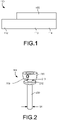
- FIG. 1 is a schematic illustration of a medical device 100 according to an embodiment.
- the medical device 100 may be used in surgical procedures.
- the medical device 100 may be placed within a body of a patient to create an access or port for further medical procedures. More specifically, in some embodiments, the medical device 100 may be placed within the body of the patient such that a distal end portion of the medical device 100 is disposed within the body of the patient and a proximal end portion of the medical device 100 extends from the body of the patient.
- an additional or secondary medical device may be inserted into the body of the patient via the medical device 100 to perform an additional medical procedure.
- the medical device 100 includes an elongate member 110 and a sleeve 150.
- the elongate member 110 has a first or proximal end portion 112 and a second or distal end portion 114.
- the elongate member 110 defines a lumen that extends from the first or proximal end portion 112 to the second or distal end portion 114.
- the elongate member 110 is linear or substantially straight or linear. In other embodiments, the elongate member 110 is curved or is flexible and may form a curve or have a curved portion. In some embodiments, the elongate member 110 may be tubular or have a round or circular cross-sectional shape. In other embodiments, the elongate member 110 has a different cross-sectional shape, such as square, rectangular, triangular, or any other shape.
- second or distal end portion 114 of the elongate member 110 may be placed in a first configuration (or collapsed configuration) or a second configuration (or expanded configuration).
- the second end portion 114 of the elongate member 110 has a first size when the second end portion 114 is in its first configuration.
- the second end portion 114 has a second size when the second end portion 114 is in its second configuration.
- the first size is smaller than the second size.
- the second end portion 114 is biased to its second or expanded configuration.
- the sleeve 150 is movably coupled to the elongate member 110.
- the sleeve 150 defines a lumen.
- the lumen may receive at least a portion of the elongate member 110 such that the elongate member 110 may move with respect to the sleeve 150.
- the sleeve 150 is configured to retain the second end portion 114 of the elongate member in its first or collapsed configuration.
- the sleeve 150 includes a contact portion or a contact surface. The contact portion or the contact surface is configured to contact the second end portion 114 of the elongate member 110 to help retain or force the second end portion 114 of the elongate member 110 in its first or collapsed configuration.
- the medical device 100 may be inserted into a body of a patient.
- the medical device 100 may be inserted into the body of the patient while the second end portion 114 of the elongate member 110 is in its first or collapsed configuration.
- the medical device 100 may be inserted into the body of the patient while the contact portion or contact surface of the sleeve 150 is in contact with the second end portion 114 of the elongate member 110 to retain the second end portion 114 of the elongate member 110 in its first or collapsed configuration.
- the medical device 100 may be inserted into the body of the patient such that the second or distal end portion 114 of the elongate member 110 is disposed within the body of the patient and the first or proximal end portion 112 of the elongate member 110 is disposed outside of the body of the patient (or extends from the body of the patient).
- the second end portion 114 may then be moved from its first or collapsed configuration to its second or expanded configuration.
- the elongate member 110 is moved with respect to the sleeve 150 such that the contact portion or contact surface of the sleeve disengages or is removed from the second end portion 114 of the elongate member 110.
- the second end portion 114 of the elongate member 110 may then move to its second or expanded configuration.
- the second end portion 114 of the elongate member 110 is biased to its second or expanded configuration and will move to such configuration in the absences of an external or retaining force.
- the second end portion 114 of the elongate member 110 is configured to retain or help retain the medical device 100 in place within the body of the patient. Specifically, in some embodiments, the second end portion 114 in its second or expanded configuration is configured to contact bodily tissue of the patient to retain or help retain the medical device 100 in place within the body of the patient.
- the elongate member 110 defines a lumen. Once the medical device 100 is disposed within the body of the patient, other medical devices may be inserted into the body of the patient though the lumen defined by the elongate member 110. Accordingly, such other or secondary medical devices may be used to perform additional medical procedures once such device is disposed within the body of the patient.
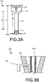
- FIGS. 2 and 3A are side views of a medical device 200 according to an embodiment.
- FIG. 3B is a cross-sectional view of a portion of the medical device 200.
- the medical device 200 may be used in surgical procedures.
- the medical device 200 may be placed within a body of a patient to create an access or port for further medical procedures.
- the medical device 200 may be placed within a body of a patient and used in a percutaneous nephrolithotomy procedure.
- FIG. 1 is a percutaneous nephrolithotomy procedure.
- the medical device 200 may be placed within the body of the patient such that a distal end portion of the medical device 200 is disposed within the body of the patient and a proximal end portion of the medical device 200 extends from the body of the patient.
- an additional or secondary medical device may be inserted into the body of the patient via the medical device 200 to perform an additional medical procedure.
- the medical device 200 includes an elongate member 210 and a sleeve 250.
- FIG. 2 illustrates the elongate member 210 with its distal end portion 214 in a first or collapsed configuration
- FIG. 3A illustrates the elongate member 210 with its distal end portion 214 in a second or expanded configuration.
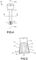
- FIG. 4 is a side view of the elongate member 210.
- FIG. 5 is a side view of the distal end portion 214 of the elongate member 210.
- FIG. 6 is a cross-sectional view of the elongate member 210 taken along line A-A of FIG. 4 .
- FIG. 7 is a cross-sectional view of the elongate member 210 taken along line B-B of FIG. 4 .
- the elongate member 210 has a first or proximal end portion 212 and a second or distal end portion 214.
- the elongate member 210 defines a lumen 216 that extends from the first or proximal end portion 212 to the second or distal end portion 214.
- the elongate member 210 is linear or substantially linear. Specifically, the elongate member 210 extends along a longitudinal axis LA1. In other embodiments, the elongate member 210 is curved or is flexible and may form a curve or have a curved portion.
- the elongate member 210 may be tubular or have a round or circular cross-sectional shape (the cross-section that is disposed orthogonal or substantially orthogonal to the longitudinal axis LA1 of the elongate member 210). In other embodiments, the elongate member 210 has a different cross-sectional shape, such as square, rectangular, triangular, or any other shape.
- the second or distal end portion 214 of the elongate member 210 may be placed in a first configuration (or collapsed configuration) or a second configuration (or expanded configuration).
- the second end portion 214 of the elongate member 210 has a first size S1 when the second end portion 214 is in its first configuration.
- the second end portion 214 is in its first configuration and has a size or width S1 when the second end portion 214 is disposed within the sleeve 250.
- the second end portion 214 has a second size or width S2 when the second end portion 214 is in its second configuration.
- the second end portion 214 is in its second configuration and has the second size S2 when the second end portion 214 is disposed outside of the sleeve 250.
- the first size S1 is smaller than the second size S2.
- the second end portion 214 is biased to its second or expanded configuration. In some embodiments, the second end portion is biased to a flared configuration or shape. As best illustrated in FIG. 5 , the second end portion 214 includes support members 222 that extend longitudinally or substantially longitudinally. The support members 222 are configured to expand or separate when the second end portion 214 is disposed outside of the sleeve 250. In some embodiments, the support members 222 are formed of a biocompatible material. In some embodiments, the support members 222 are formed of the same material that is used to form the sleeve 250. In some embodiments, the support members 222 have a thickness that is larger than the thickness of the sleeve 250. Extension portions 223 extend between the support members 222.
- the extension portions 223 are more flexible than the support members 222. In some embodiments, the flexibility of the extension portions 223 facilitates the expansion of the second end portion 214 to its larger or flared configuration. In some embodiments, the extension portions 223 are formed of a material that is more flexible than the material that is used to form the support members 222. In some embodiments, the second end portion 214 can be formed of a molded thermoplastic or a shaped metal material or a metal support on a polymeric member. In some embodiments, the support members 222 may be formed of acetal or polyetherimide. In other embodiments, the support members 222 are formed of polyethylene, polypropylene, polyvinyl chloride, nitinol or stainless steel.
- an outer surface 221 of the second end portion 214 is configured to grip or adhere to bodily tissue of the patient to help retain the device 200 in place within the body of the patient.
- the outer surface 221 includes an material or a coating that has a relatively high coefficient of friction to help grip or adhere to the bodily tissue or anatomy of the patient.
- the second end portion 214 includes anchoring members or points 225.
- the anchoring members or points 225 may be raised or protruding portions that help the second end portion 214 grip or adhere to the bodily tissue or anatomy of the patient when the device is in its expanded configuration.
- the anchoring members or points 225 may be of any shape or size. In some embodiments, the anchoring members or points 225 are rectangular in shape. In other embodiments, the anchoring members or points 225 are circular in shape. In some embodiments, the anchoring members or points 225 may be circumferentially distributed or arraigned in a row or a plurality of rows.
- a gel may coat or cover a portion of the anchoring members 225.
- the gel may be a biodegradable or medical gel and may have a relatively high coefficient of friction.
- the gel may help the second end portion 214 grip or adhere to the bodily tissue or anatomy of the patient when the device is in its expanded configuration.
- the gel may be gel pads.
- the gel may be or include a silicone gel.
- FIG. 8 is a side view of the sleeve 250.
- FIG. 9 is a cross-sectional view of the sleeve 250 taken along line C-C (which is orthogonal or substantially orthogonal to the longitudinal axis LA2 of the sleeve 250) of FIG. 8 .
- FIG. 10 is another cross-sectional view of the sleeve 250.
- the sleeve 250 is movably coupled to the elongate member 210.
- the sleeve 250 defines a lumen 256.
- the lumen 256 extends from a first end portion 252 of the sleeve 250 to a second end portion 254 of the sleeve.
- the lumen 256 may receive at least a portion of the elongate member 210 such that the elongate member 210 may move or slide with respect to the sleeve 250.
- the sleeve 250 is configured to retain the second end portion 214 of the elongate member 210 in its first or collapsed configuration.
- the sleeve 250 includes a contact portion or a contact surface 259.
- the contact portion or the contact surface 259 is an inner surface of the sleeve 250 and is configured to contact the second end portion 214 of the elongate member 210 to help retain or force the second end portion 214 of the elongate member 210 in its first or collapsed configuration.
- the sleeve 250 includes an enlarged portion 257 disposed at the first or proximal end portion 252 of the sleeve 250.
- the enlarged portion 257 is configured to be larger than the remaining length of the sleeve 250.
- the enlarged portion 257 is configured to help prevent the sleeve 250 from being entirely disposed within the body of the patient.
- the enlarged portion 257 is configured to contact an other surface or outer portion of the body of the patient to help prevent the sleeve 250 from being entirely disposed within the body of the patient.
- the elongate member 210 has a length that is greater than a length of the sleeve 250. As best illustrated in FIG. 3A , the elongate member 210 has a length L1 along its longitudinal axis LA1 and the sleeve 250 has a length L2 along its longitudinal axis LA2. The length L1 is greater than the length L2.
- the medical device 200 may be inserted into a body of a patient (as schematically illustrated in FIG. 11 ).
- the medical device 200 may be inserted into the body of the patient while the second end portion 214 of the elongate member 210 is in its first or collapsed configuration.
- the medical device 200 may be inserted into the body of the patient while the contact portion or contact surface 259 of the sleeve 250 is in contact with the second end portion 214 of the elongate member 210 to retain the second end portion 214 of the elongate member 210 in its first or collapsed configuration.
- the medical device 200 may be inserted into the body of the patient while the second end portion 214 of the elongate member 210 is disposed within the lumen 256 of the sleeve 250.
- the medical device 200 may be inserted into the body of the patient such that the second or distal end portion 214 of the elongate member 210 is disposed within the body of the patient and the first or proximal end portion 212 of the elongate member 210 is disposed outside of the body of the patient (or extends from the body of the patient). As illustrated in FIG. 11 , a distal end portion 202 of the medical device 200 extends from an outer surface OS of the body of the patient.
- the second end portion 214 may then be moved from its first or collapsed configuration to its second or expanded configuration.
- the elongate member 210 is moved with respect to the sleeve 250 such that the contact portion or contact surface 259 of the sleeve 250 disengages or is removed from the second end portion 214 of the elongate member 210.
- the sleeve 250 may be moved in the direction of arrow M (as illustrated in FIG. 3A ) to disengage the contact portion or the contact surface 259 from the second end portion 214 (i.e., remove the second end portion 214 from the lumen 256 of the sleeve 250).
- the second end portion 214 of the elongate member 210 may then move to its second or expanded configuration.
- the second end portion 214 of the elongate member 210 is biased to its second or expanded configuration and will move to such configuration in the absences of an external or retaining force.
- an inner surface 251 of the sleeve 250 may include a cam or otherwise uneven surface.
- the elongate member 210 may be rotated in an opposite direction to disengage or unlock the elongate member 210 from the sleeve.
- a different type of coupling mechanism may be used to removably couple or fix the elongate member 210 with respect to the sleeve 250.
- the coupling mechanism used to removably couple or fix the elongate member 210 with respect to the sleeve 250 is a helical threaded screw type mechanism.
- the elongate member 210 may be rotated with respect to the sleeve 250 to move the elongate member 210 linearly with respect to the sleeve 250.
- the second end portion 214 of the elongate member 210 is configured to retain or help retain the medical device 200 in place within the body of the patient. Specifically, as illustrated in FIG. 11 , the second end portion 214 in its second or expanded configuration is configured to contact bodily tissue BT of the patient to retain or help retain the medical device 200 in place within the body of the patient.
- the medical device 200 once the medical device 200 is disposed within the body of the patient, other medical devices may be inserted into the body of the patient though the lumen 216 defined by the elongate member 210. Accordingly, such other or secondary medical devices may be used to perform additional medical procedures once such device is disposed within the body of the patient.
- the proximal end portion 212 of the elongate member 210 includes a hub 230.
- the hub 230 defines a lumen 232.
- the lumen or opening 232 of the hub is in fluid communication with the lumen 216 of the elongate member 210.
- the lumen or opening 232 of the hub 230 is tapered or funnel shaped. In other words, there is a portion of the opening or lumen that is larger or wider than another portion of the opening or lumen.
- the lumen or opening of the hub 230 funnels down to the lumen 216 of the elongate member 210.
- the funnel shaped lumen 232 of the hub 230 may help funnel the secondary medical devices down to and guide them to the lumen 216 of the elongate member 210.
- an inner surface 234 of the hub 230 may guide secondary medical devices into the lumen 216 of the elongate member 210.
- the inner surface 234 may contact the secondary medical devices and help couple or retain the secondary medical devices in place once they are disposed within the lumen 216 of the elongate member 210.
- the inner surface 234 may frictionally retain or couple the secondary medical devices in place within the medical device 200.
- the hub 230 includes a lever 239.
- the lever 239 is configured to be moved to from a first position to a second position to contact the secondary medical device SMD to help couple the secondary medical device within the lumen 216 of the elongate member 210. In some embodiments, the lever 239 may be rotated or twisted to move into and out of engagement with the secondary medical device.
- FIG. 12 is a flow chart of an exemplary method.
- a medical device is inserted into a body of a patient.
- the elongate member of the medical device is moved with respect to the sleeve of the medical device. The movement allows a portion of the elongate member to move from a collapsed configuration to an expanded configuration. Accordingly, in some embodiments, the expanded configuration of the elongate member helps secure or anchor the medical device within the body of the patient.
Landscapes
- Health & Medical Sciences (AREA)
- Surgery (AREA)
- Life Sciences & Earth Sciences (AREA)
- Medical Informatics (AREA)
- Nuclear Medicine, Radiotherapy & Molecular Imaging (AREA)
- Engineering & Computer Science (AREA)
- Biomedical Technology (AREA)
- Heart & Thoracic Surgery (AREA)
- Molecular Biology (AREA)
- Animal Behavior & Ethology (AREA)
- General Health & Medical Sciences (AREA)
- Public Health (AREA)
- Veterinary Medicine (AREA)
- Pathology (AREA)
- Media Introduction/Drainage Providing Device (AREA)
- Surgical Instruments (AREA)
Description
- This disclosure relates generally to medical devices and more particularly to medical devices such as access devices or sheaths that include anchoring features.
- A variety of medical procedures are performed using an access device or an access sheath. For example, access devices or access sheaths may be used in procedures such as percutaneous nephrolithotomy procedures.
- For instance,
US 2013/197592 A1 appears to describe an apparatus for an anchoring cannula including a first cannula, a second cannula concentrically arranged within the lumen of the first cannula, the second cannula including an expandable portion connected to the distal end that is configured to expand when the second cannula is advanced out of the distal end of the first cannula and to change to an unexpanded configuration when retracted back into the distal end of the first cannula. -
US 8 817 062 A appears to describe a thoracic trocar including an inner member having a number of arms at a distal end, the arms being naturally biased to an open position and being maintained in a closed position by an outer member. -
WO 00/62689 A1 -
US 2009/105691 A1 appears to disclose an anchoring cannula possessing a shape memory polymer on the distal portion thereof which expands upon heating thereby securing the cannula in tissue. - In some procedures that use access devices or access sheaths, it may be difficult for a physician or other medical practitioner to maintain the placement of the access device or the access sheath within the body or be unintentionally dislodged from the its desired position within the body of the patient.
- Accordingly, is may be desirable to provide a device, such as an access device or access sheath that includes features or components that help facilitate the securement of the access device or access sheath within the body of the patient.
- The invention is defined by claim 1. Further embodiments of the invention are defined by the dependent claims.
- According to an aspect, a medical device includes an elongate member and a sleeve, The elongate member defines a lumen and has a first end portion and a second end portion. The second end portion has a first configuration and a second configuration. The second end portion has a first size when the second end portion is in its first configuration and a second size when the second end portion is in its second configuration. The first size is smaller than the second size. The second end portion is biased to its second configuration. The sleeve defines a lumen extending from a first end portion of the sleeve to a second end portion of the sleeve. The lumen is configured to movably receive at least a portion of the elongate member. The sleeve is configured to engage the second end portion of the elongate member to help retain the second end portion of the elongate member in its first configuration.
- In some embodiments, the lumen defined by the elongate member extends from the first end portion of the elongate member to the second end portion of the elongate member.
- In some embodiments, the elongate member defines a longitudinal axis, the at least a portion of the elongate member being movably received by the sleeve such that the elongate member may move in a direction substantially parallel to the longitudinal axis of the elongate member.
- In some embodiments the elongate member is configured to rotate with respect to the sleeve.
- In some embodiments, the elongate member includes a hub member, the hub member defines an opening, the opening being in fluid communication with the lumen of the elongate member. In some embodiments, the elongate member includes a hub member, the hub member defines a funnel shaped opening, the funnel shaped opening being in fluid communication with the lumen of the elongate member.
- In some embodiments, the elongate member having a longitudinal length, the sleeve having a longitudinal length, the longitudinal length of the elongate member being greater than the longitudinal length of the sleeve.
- In some embodiments, the second end portion of the elongate member includes a plurality of support members.
- In some embodiments, the elongate member is configured to be locked in position with respect to the sleeve. In some embodiments, the elongate member is configured to be locked in position with respect to the sleeve via a frictional coupling between a portion of the elongate member and a portion of the sleeve. In some embodiments, the elongate member includes a first locking feature, the sleeve includes a second locking feature, the first locking feature being configured to engage the second locking feature to lock the elongate member with respect to the sleeve.
- In some embodiments, the lumen of the elongate member is configured to receive a secondary medical device.
- In some embodiments, the sleeve includes an inner surface, at least a portion of the inner surface of the sleeve being configured to engage the second end portion of the elongate member to help retain the elongate member in its first configuration.
- In some embodiments, the medical device is configured to be inserted into a body of a patient. In some embodiments, the medical device is configured to be inserted into a body of a patient and the lumen of the elongate member is configured to receive at least a portion of a secondary medical device.
- In another aspect, a medical device includes an elongate member and a sleeve. The elongate member defines a lumen and has a first end portion and a second end portion. The second end portion has a first configuration and a second configuration. The second end portion has a first size when the second end portion is in its first configuration and a second size when the second end portion is in its second configuration. The first size being smaller than the second size. The second end portion is biased to its second configuration. The sleeve is movably coupled to the elongate member. The sleeve has a contact surface. The contact surface is configured to contact the second end portion of the elongate member to help retain the elongate member in its first configuration.
- In some embodiments, the elongate member is configured to rotate with respect to the sleeve. In some embodiments, the elongate member includes a hub member, the hub member defines an opening, the opening being in fluid communication with the lumen of the elongate member. In some embodiments, the elongate member includes a hub member, the hub member defines a funnel shaped opening, the funnel shaped opening being in fluid communication with the lumen of the elongate member.
- In some embodiments, the second end portion of the elongate member includes a plurality of support members.
- In some embodiments, an exemplary method includes inserting a medical device into a body of a patient, the medical device including an elongate member and a sleeve; and moving the elongate member with respect to the sleeve such that an end portion of the elongate member moves away from an end portion of the sleeve and moves from a collapsed configuration to an expanded configuration. In some embodiments, the moving the elongate member with respect to the sleeve includes rotating the elongate member with respect to the sleeve.
-
-
FIG. 1 is a schematic illustration of a medical device according to an embodiment. -
FIGS. 2 and3A are side views of a medical device according to an embodiment. -
FIG. 3B is a cross-sectional view of a portion of the medical device ofFIGS. 2 and3A . -
FIG. 4 is a side view of an elongate member of the medical device ofFIGS. 2 and3A . -
FIG. 5 is a side view of a distal end portion of the elongate member ofFIG. 4 . -
FIG. 6 is a cross-sectional view of the elongate member ofFIG. 4 taken along line A-A ofFIG. 4 . -
FIG. 7 is a cross-sectional view of the elongate member ofFIG. 4 taken along line B-B ofFIG. 4 . -
FIG. 8 is a side view of a sleeve of the medical device ofFIGS. 2 and3A . -
FIG. 9 is a cross-sectional view of the sleeve ofFIG. 8 taken along line C-C ofFIG. 8 . -
FIG. 10 is a cross-sectional view of the sleeve ofFIG. 8 taken along line D-D ofFIG. 8 . -
FIG. 11 is a schematic view of the medical device ofFIGS. 2 and3A disposed within a body of a patient. -
FIG. 12 is a flow chart of an exemplary method not according to the invention. - Detailed embodiments are disclosed herein. However, it is understood that the disclosed embodiments are merely examples, which may be embodied in various forms. Therefore, specific structural and functional details disclosed herein are not to be interpreted as limiting, but merely as a basis for the claims and as a representative basis for teaching one skilled in the art to variously employ the embodiments in virtually any appropriately detailed structure. Further, the terms and phrases used herein are not intended to be limiting, but to provide an understandable description of the invention.
- The terms "a" or "an," as used herein, are defined as one or more than one. The term "another," as used herein, is defined as at least a second or more. The terms "including" and/or "having", as used herein, are defined as comprising (i.e., open transition).
- The term patient may hereafter be used for a person who benefits from the medical device or the exemplary methods disclosed in the present application. For example, the patient can be a person whose body is operated through the medical device or the method disclosed by the present disclosure. For example, in some aspects, the patient may be a human female, a human male, or any other mammal.
- The terms proximal and distal described in relation to various devices, apparatuses, and components as discussed in the subsequent text of the present application are referred with a point of reference. The point of reference, as used in this description, is a perspective of an operator. The operator may be a surgeon, a physician, a nurse, a doctor, a technician, and the like who may perform the procedure and operate the medical device as described in the present invention. The term proximal refers to an area or portion that is closer or closest to the operator during a surgical procedure. The term distal refers to an area or portion that is farther or farthest from the operator.
-
FIG. 1 is a schematic illustration of amedical device 100 according to an embodiment. Themedical device 100 may be used in surgical procedures. For example, in some embodiments themedical device 100 may be placed within a body of a patient to create an access or port for further medical procedures. More specifically, in some embodiments, themedical device 100 may be placed within the body of the patient such that a distal end portion of themedical device 100 is disposed within the body of the patient and a proximal end portion of themedical device 100 extends from the body of the patient. In some embodiments, an additional or secondary medical device may be inserted into the body of the patient via themedical device 100 to perform an additional medical procedure. - In the illustrated embodiment, the
medical device 100 includes anelongate member 110 and asleeve 150. Theelongate member 110 has a first orproximal end portion 112 and a second ordistal end portion 114. In some embodiments, theelongate member 110 defines a lumen that extends from the first orproximal end portion 112 to the second ordistal end portion 114. - In some embodiments, the
elongate member 110 is linear or substantially straight or linear. In other embodiments, theelongate member 110 is curved or is flexible and may form a curve or have a curved portion. In some embodiments, theelongate member 110 may be tubular or have a round or circular cross-sectional shape. In other embodiments, theelongate member 110 has a different cross-sectional shape, such as square, rectangular, triangular, or any other shape. - In some embodiments, second or
distal end portion 114 of theelongate member 110 may be placed in a first configuration (or collapsed configuration) or a second configuration (or expanded configuration). Thesecond end portion 114 of theelongate member 110 has a first size when thesecond end portion 114 is in its first configuration. Thesecond end portion 114 has a second size when thesecond end portion 114 is in its second configuration. The first size is smaller than the second size. In some embodiments, thesecond end portion 114 is biased to its second or expanded configuration. - The
sleeve 150 is movably coupled to theelongate member 110. In some embodiments, thesleeve 150 defines a lumen. In such embodiments, the lumen may receive at least a portion of theelongate member 110 such that theelongate member 110 may move with respect to thesleeve 150. - The
sleeve 150 is configured to retain thesecond end portion 114 of the elongate member in its first or collapsed configuration. In some embodiments, thesleeve 150 includes a contact portion or a contact surface. The contact portion or the contact surface is configured to contact thesecond end portion 114 of theelongate member 110 to help retain or force thesecond end portion 114 of theelongate member 110 in its first or collapsed configuration. - In use, the
medical device 100 may be inserted into a body of a patient. In some embodiments, themedical device 100 may be inserted into the body of the patient while thesecond end portion 114 of theelongate member 110 is in its first or collapsed configuration. For example, in some embodiments, themedical device 100 may be inserted into the body of the patient while the contact portion or contact surface of thesleeve 150 is in contact with thesecond end portion 114 of theelongate member 110 to retain thesecond end portion 114 of theelongate member 110 in its first or collapsed configuration. - In some embodiments, the
medical device 100 may be inserted into the body of the patient such that the second ordistal end portion 114 of theelongate member 110 is disposed within the body of the patient and the first orproximal end portion 112 of theelongate member 110 is disposed outside of the body of the patient (or extends from the body of the patient). - The
second end portion 114 may then be moved from its first or collapsed configuration to its second or expanded configuration. For example, in some embodiments, theelongate member 110 is moved with respect to thesleeve 150 such that the contact portion or contact surface of the sleeve disengages or is removed from thesecond end portion 114 of theelongate member 110. Thesecond end portion 114 of theelongate member 110 may then move to its second or expanded configuration. In some embodiments, thesecond end portion 114 of theelongate member 110 is biased to its second or expanded configuration and will move to such configuration in the absences of an external or retaining force. - In some embodiments, the
second end portion 114 of theelongate member 110 is configured to retain or help retain themedical device 100 in place within the body of the patient. Specifically, in some embodiments, thesecond end portion 114 in its second or expanded configuration is configured to contact bodily tissue of the patient to retain or help retain themedical device 100 in place within the body of the patient. - In some embodiments, the
elongate member 110 defines a lumen. Once themedical device 100 is disposed within the body of the patient, other medical devices may be inserted into the body of the patient though the lumen defined by theelongate member 110. Accordingly, such other or secondary medical devices may be used to perform additional medical procedures once such device is disposed within the body of the patient. -
FIGS. 2 and3A are side views of amedical device 200 according to an embodiment.FIG. 3B is a cross-sectional view of a portion of themedical device 200. Themedical device 200 may be used in surgical procedures. For example, in some embodiments themedical device 200 may be placed within a body of a patient to create an access or port for further medical procedures. For example, in some embodiments, themedical device 200 may be placed within a body of a patient and used in a percutaneous nephrolithotomy procedure. In some embodiments, as best illustrated inFIG. 11 , themedical device 200 may be placed within the body of the patient such that a distal end portion of themedical device 200 is disposed within the body of the patient and a proximal end portion of themedical device 200 extends from the body of the patient. In some embodiments, an additional or secondary medical device may be inserted into the body of the patient via themedical device 200 to perform an additional medical procedure. - In the illustrated embodiment, the
medical device 200 includes anelongate member 210 and asleeve 250. As will be described in more detail below,FIG. 2 illustrates theelongate member 210 with itsdistal end portion 214 in a first or collapsed configuration andFIG. 3A illustrates theelongate member 210 with itsdistal end portion 214 in a second or expanded configuration. -
FIG. 4 is a side view of theelongate member 210.FIG. 5 is a side view of thedistal end portion 214 of theelongate member 210.FIG. 6 is a cross-sectional view of theelongate member 210 taken along line A-A ofFIG. 4 .FIG. 7 is a cross-sectional view of theelongate member 210 taken along line B-B ofFIG. 4 . - The
elongate member 210 has a first orproximal end portion 212 and a second ordistal end portion 214. Theelongate member 210 defines alumen 216 that extends from the first orproximal end portion 212 to the second ordistal end portion 214. - In the illustrated embodiment, the
elongate member 210 is linear or substantially linear. Specifically, theelongate member 210 extends along a longitudinal axis LA1. In other embodiments, theelongate member 210 is curved or is flexible and may form a curve or have a curved portion. - As best illustrated in
FIG. 6 , theelongate member 210 may be tubular or have a round or circular cross-sectional shape (the cross-section that is disposed orthogonal or substantially orthogonal to the longitudinal axis LA1 of the elongate member 210). In other embodiments, theelongate member 210 has a different cross-sectional shape, such as square, rectangular, triangular, or any other shape. - The second or
distal end portion 214 of theelongate member 210 may be placed in a first configuration (or collapsed configuration) or a second configuration (or expanded configuration). Thesecond end portion 214 of theelongate member 210 has a first size S1 when thesecond end portion 214 is in its first configuration. For example, as will be described in detail below and as illustrated inFIG. 2 , thesecond end portion 214 is in its first configuration and has a size or width S1 when thesecond end portion 214 is disposed within thesleeve 250. Thesecond end portion 214 has a second size or width S2 when thesecond end portion 214 is in its second configuration. As best illustrated inFIG. 3A , thesecond end portion 214 is in its second configuration and has the second size S2 when thesecond end portion 214 is disposed outside of thesleeve 250. The first size S1 is smaller than the second size S2. - In the illustrated embodiment, the
second end portion 214 is biased to its second or expanded configuration. In some embodiments, the second end portion is biased to a flared configuration or shape. As best illustrated inFIG. 5 , thesecond end portion 214 includessupport members 222 that extend longitudinally or substantially longitudinally. Thesupport members 222 are configured to expand or separate when thesecond end portion 214 is disposed outside of thesleeve 250. In some embodiments, thesupport members 222 are formed of a biocompatible material. In some embodiments, thesupport members 222 are formed of the same material that is used to form thesleeve 250. In some embodiments, thesupport members 222 have a thickness that is larger than the thickness of thesleeve 250.Extension portions 223 extend between thesupport members 222. In some embodiments, theextension portions 223 are more flexible than thesupport members 222. In some embodiments, the flexibility of theextension portions 223 facilitates the expansion of thesecond end portion 214 to its larger or flared configuration. In some embodiments, theextension portions 223 are formed of a material that is more flexible than the material that is used to form thesupport members 222. In some embodiments, thesecond end portion 214 can be formed of a molded thermoplastic or a shaped metal material or a metal support on a polymeric member. In some embodiments, thesupport members 222 may be formed of acetal or polyetherimide. In other embodiments, thesupport members 222 are formed of polyethylene, polypropylene, polyvinyl chloride, nitinol or stainless steel. - In some embodiments, an
outer surface 221 of thesecond end portion 214 is configured to grip or adhere to bodily tissue of the patient to help retain thedevice 200 in place within the body of the patient. In some embodiments, theouter surface 221 includes an material or a coating that has a relatively high coefficient of friction to help grip or adhere to the bodily tissue or anatomy of the patient. In some embodiments, in accordance with the present claimed invention, thesecond end portion 214 includes anchoring members or points 225. - The anchoring members or points 225 may be raised or protruding portions that help the
second end portion 214 grip or adhere to the bodily tissue or anatomy of the patient when the device is in its expanded configuration. The anchoring members or points 225 may be of any shape or size. In some embodiments, the anchoring members or points 225 are rectangular in shape. In other embodiments, the anchoring members or points 225 are circular in shape. In some embodiments, the anchoring members or points 225 may be circumferentially distributed or arraigned in a row or a plurality of rows. - In some embodiments, a gel may coat or cover a portion of the anchoring
members 225. The gel may be a biodegradable or medical gel and may have a relatively high coefficient of friction. Thus, in some embodiments, the gel may help thesecond end portion 214 grip or adhere to the bodily tissue or anatomy of the patient when the device is in its expanded configuration. In some embodiments, the gel may be gel pads. In some embodiments, the gel may be or include a silicone gel. -
FIG. 8 is a side view of thesleeve 250.FIG. 9 is a cross-sectional view of thesleeve 250 taken along line C-C (which is orthogonal or substantially orthogonal to the longitudinal axis LA2 of the sleeve 250) ofFIG. 8 .FIG. 10 is another cross-sectional view of thesleeve 250. Thesleeve 250 is movably coupled to theelongate member 210. In in the illustrated embodiment, thesleeve 250 defines alumen 256. Thelumen 256 extends from afirst end portion 252 of thesleeve 250 to asecond end portion 254 of the sleeve. Thelumen 256 may receive at least a portion of theelongate member 210 such that theelongate member 210 may move or slide with respect to thesleeve 250. - The
sleeve 250 is configured to retain thesecond end portion 214 of theelongate member 210 in its first or collapsed configuration. In the illustrated embodiment, thesleeve 250 includes a contact portion or acontact surface 259. The contact portion or thecontact surface 259 is an inner surface of thesleeve 250 and is configured to contact thesecond end portion 214 of theelongate member 210 to help retain or force thesecond end portion 214 of theelongate member 210 in its first or collapsed configuration. - In the illustrated embodiment, the
sleeve 250 includes anenlarged portion 257 disposed at the first orproximal end portion 252 of thesleeve 250. Theenlarged portion 257 is configured to be larger than the remaining length of thesleeve 250. In some embodiments, theenlarged portion 257 is configured to help prevent thesleeve 250 from being entirely disposed within the body of the patient. For example, in some embodiments, theenlarged portion 257 is configured to contact an other surface or outer portion of the body of the patient to help prevent thesleeve 250 from being entirely disposed within the body of the patient. - In the illustrated embodiment, the
elongate member 210 has a length that is greater than a length of thesleeve 250. As best illustrated inFIG. 3A , theelongate member 210 has a length L1 along its longitudinal axis LA1 and thesleeve 250 has a length L2 along its longitudinal axis LA2. The length L1 is greater than the length L2. - In use, the
medical device 200 may be inserted into a body of a patient (as schematically illustrated inFIG. 11 ). In some embodiments, themedical device 200 may be inserted into the body of the patient while thesecond end portion 214 of theelongate member 210 is in its first or collapsed configuration. For example, in some embodiments, themedical device 200 may be inserted into the body of the patient while the contact portion orcontact surface 259 of thesleeve 250 is in contact with thesecond end portion 214 of theelongate member 210 to retain thesecond end portion 214 of theelongate member 210 in its first or collapsed configuration. In some embodiments, themedical device 200 may be inserted into the body of the patient while thesecond end portion 214 of theelongate member 210 is disposed within thelumen 256 of thesleeve 250. - In some embodiments, the
medical device 200 may be inserted into the body of the patient such that the second ordistal end portion 214 of theelongate member 210 is disposed within the body of the patient and the first orproximal end portion 212 of theelongate member 210 is disposed outside of the body of the patient (or extends from the body of the patient). As illustrated inFIG. 11 , adistal end portion 202 of themedical device 200 extends from an outer surface OS of the body of the patient. - The
second end portion 214 may then be moved from its first or collapsed configuration to its second or expanded configuration. For example, in some embodiments, theelongate member 210 is moved with respect to thesleeve 250 such that the contact portion orcontact surface 259 of thesleeve 250 disengages or is removed from thesecond end portion 214 of theelongate member 210. For example, in the illustrated embodiment, thesleeve 250 may be moved in the direction of arrow M (as illustrated inFIG. 3A ) to disengage the contact portion or thecontact surface 259 from the second end portion 214 (i.e., remove thesecond end portion 214 from thelumen 256 of the sleeve 250). - The
second end portion 214 of theelongate member 210 may then move to its second or expanded configuration. In some embodiments, thesecond end portion 214 of theelongate member 210 is biased to its second or expanded configuration and will move to such configuration in the absences of an external or retaining force. - In the illustrated embodiment, once the
sleeve 250 is moved such that thesecond end portion 214 of theelongate member 210 extends from the sleeve 250 (as illustrated inFIG. 3A ), the position of theelongate member 210 with respect to thesleeve 250 may be locked or fixed. In the illustrated embodiment, theelongate member 210 may be rotated in the direction of arrow N to lock or fix theelongate member 210 with respect to thesleeve 250. For example, in some embodiments, aninner surface 251 of thesleeve 250 may include a cam or otherwise uneven surface. As theelongate member 210 is rotated or twisted, in accordance with the present claimed invention, the inner surface frictionally couples theelongate member 210 to thesleeve 250. Theelongate member 210 may be rotated in an opposite direction to disengage or unlock theelongate member 210 from the sleeve. In other embodiments, a different type of coupling mechanism may be used to removably couple or fix theelongate member 210 with respect to thesleeve 250. In some embodiments, the coupling mechanism used to removably couple or fix theelongate member 210 with respect to thesleeve 250 is a helical threaded screw type mechanism. For example, theelongate member 210 may be rotated with respect to thesleeve 250 to move theelongate member 210 linearly with respect to thesleeve 250. - In some embodiments, the
second end portion 214 of theelongate member 210 is configured to retain or help retain themedical device 200 in place within the body of the patient. Specifically, as illustrated inFIG. 11 , thesecond end portion 214 in its second or expanded configuration is configured to contact bodily tissue BT of the patient to retain or help retain themedical device 200 in place within the body of the patient. - In some embodiments, once the
medical device 200 is disposed within the body of the patient, other medical devices may be inserted into the body of the patient though thelumen 216 defined by theelongate member 210. Accordingly, such other or secondary medical devices may be used to perform additional medical procedures once such device is disposed within the body of the patient. - In the illustrated embodiment, the
proximal end portion 212 of theelongate member 210 includes ahub 230. Thehub 230 defines alumen 232. The lumen or opening 232 of the hub is in fluid communication with thelumen 216 of theelongate member 210. In the illustrated embodiment, the lumen or opening 232 of thehub 230 is tapered or funnel shaped. In other words, there is a portion of the opening or lumen that is larger or wider than another portion of the opening or lumen. In the illustrated embodiment, the lumen or opening of thehub 230 funnels down to thelumen 216 of theelongate member 210. - In some embodiments, the funnel shaped
lumen 232 of thehub 230 may help funnel the secondary medical devices down to and guide them to thelumen 216 of theelongate member 210. For example, in the illustrated embodiment, aninner surface 234 of thehub 230 may guide secondary medical devices into thelumen 216 of theelongate member 210. Additionally, in some embodiments, theinner surface 234 may contact the secondary medical devices and help couple or retain the secondary medical devices in place once they are disposed within thelumen 216 of theelongate member 210. For example, in some embodiments, theinner surface 234 may frictionally retain or couple the secondary medical devices in place within themedical device 200. As best illustrated inFIG. 3B , in the illustrated embodiment, thehub 230 includes alever 239. Thelever 239 is configured to be moved to from a first position to a second position to contact the secondary medical device SMD to help couple the secondary medical device within thelumen 216 of theelongate member 210. In some embodiments, thelever 239 may be rotated or twisted to move into and out of engagement with the secondary medical device. -
FIG. 12 is a flow chart of an exemplary method. At 410, a medical device is inserted into a body of a patient. At 420, the elongate member of the medical device is moved with respect to the sleeve of the medical device. The movement allows a portion of the elongate member to move from a collapsed configuration to an expanded configuration. Accordingly, in some embodiments, the expanded configuration of the elongate member helps secure or anchor the medical device within the body of the patient. - While certain features of the described implementations have been illustrated as described herein, many modifications, substitutions, changes and equivalents will now occur to those skilled in the art. The invention is defined by the following claims.
Claims (12)
- A medical access device (200), comprising:an elongate member (210) defining a lumen (216) and having a first end portion (212) and a second end portion (214), the second end portion (214) having a first configuration and a second configuration, the second end portion (214) having a first size when the second end portion (214) is in its first configuration and a second size when the second end portion (214) is in its second configuration, the first size being smaller than the second size, the second end portion (214) being biased to its second configuration, the second end portion including anchoring members or points (225); anda sleeve (250) defining a lumen (256) extending from a first end portion (252) of the sleeve (250) to a second end portion (254) of the sleeve (250), the lumen (256) being configured to movably receive at least a portion of the elongate member (210), the sleeve (250) being configured to engage the second end portion (214) of the elongate member (210) to help retain the second end portion (214) of the elongate member (110) in its first configuration,wherein the elongate member (210) is configured to rotate with respect to the sleeve (250) such as to lock the elongate member (210) in position with respect to the sleeve (250) via a frictional coupling between a portion of the elongate member (210) and a portion of the sleeve (250).
- The medical access device of claim 1, wherein the lumen (216) defined by the elongate member (210) extends from the first end portion (212) of the elongate member (210) to the second end portion (214) of the elongate member (210).
- The medical access device (200) of any of claims 1 and 2, wherein the elongate member (210) defines a longitudinal axis, the at least a portion of the elongate member (210) being movably received by the sleeve (250) such that the elongate member (210) may move in a direction substantially parallel to the longitudinal axis of the elongate member (210).
- The medical access device (200) of any of claims 1-3, wherein the elongate member (210) includes a hub member (230), the hub member (230) defines an opening (232), the opening (232) being in fluid communication with the lumen (216) of the elongate member (210).
- The medical access device (200) of any of claims 1-3, wherein the elongate member (210) includes a hub member (230), the hub member (230) defines a funnel shaped opening (232), the funnel shaped opening (232) being in fluid communication with the lumen (216) of the elongate member (210).
- The medical access device (200) of any of claims 1-5, wherein the elongate member (210) having a longitudinal length, the sleeve (250) having a longitudinal length, the longitudinal length of the elongate member (210) being greater than the longitudinal length of the sleeve (250).
- The medical access device (200) of any of claims 1-6, wherein the second end portion (214) of the elongate member (210) includes a plurality of support members (222).
- The medical access device (200) of any of claims 1-7, wherein the elongate member (210) includes a first locking feature, the sleeve (250) includes a second locking feature, the first locking feature being configured to engage the second locking feature to lock the elongate member (210) with respect to the sleeve (250).
- The medical access device (200) of any of claims 1-8, wherein the lumen (216) of the elongate member (210) is configured to receive a secondary medical device.
- The medical access device (200) of any of claims 1-9, wherein the sleeve (250) includes an inner surface (251), at least a portion of the inner surface (251) of the sleeve (250) being configured to engage the second end portion (214) of the elongate member (210) to help retain the elongate member (210) in its first configuration.
- The medical access device (200) of any of claims 1-10, wherein the medical device (200) is configured to be inserted into a body of a patient.
- The medical access device (200) of any of claims 1-10, wherein the medical device (200) is configured to be inserted into a body of a patient and the lumen (216) of the elongate member (210) is configured to receive at least a portion of a secondary medical device.
Applications Claiming Priority (3)
| Application Number | Priority Date | Filing Date | Title |
|---|---|---|---|
| US201662288925P | 2016-01-29 | 2016-01-29 | |
| US15/412,864 US11006941B2 (en) | 2016-01-29 | 2017-01-23 | Access device having an anchoring feature and methods of using the same |
| PCT/US2017/014698 WO2017132125A1 (en) | 2016-01-29 | 2017-01-24 | Access device having an anchoring feature and methods of using the same |
Publications (2)
| Publication Number | Publication Date |
|---|---|
| EP3407811A1 EP3407811A1 (en) | 2018-12-05 |
| EP3407811B1 true EP3407811B1 (en) | 2022-05-04 |
Family
ID=59386321
Family Applications (1)
| Application Number | Title | Priority Date | Filing Date |
|---|---|---|---|
| EP17704132.4A Active EP3407811B1 (en) | 2016-01-29 | 2017-01-24 | Access device having an anchoring feature |
Country Status (4)
| Country | Link |
|---|---|
| US (2) | US11006941B2 (en) |
| EP (1) | EP3407811B1 (en) |
| CN (1) | CN109414278B (en) |
| WO (1) | WO2017132125A1 (en) |
Families Citing this family (6)
| Publication number | Priority date | Publication date | Assignee | Title |
|---|---|---|---|---|
| US11006941B2 (en) * | 2016-01-29 | 2021-05-18 | Boston Scientific Limited | Access device having an anchoring feature and methods of using the same |
| DE102018208564A1 (en) | 2018-05-30 | 2019-12-05 | Kardion Gmbh | Controllable introducer sheath |
| DE102018208555A1 (en) | 2018-05-30 | 2019-12-05 | Kardion Gmbh | Apparatus for anchoring a cardiac assist system in a blood vessel, method of operation, and method of making a device and cardiac assist system |
| DE102018208537A1 (en) | 2018-05-30 | 2019-12-05 | Kardion Gmbh | Device for connecting a cardiac assist system to an insertion device and method for producing a device for connecting a cardiac assist system to an insertion device |
| DE102018211297A1 (en) | 2018-07-09 | 2020-01-09 | Kardion Gmbh | Cardiac support system and method for monitoring the integrity of a support structure of a cardiac support system |
| US12589237B2 (en) | 2020-11-20 | 2026-03-31 | Kardion Gmbh | Mechanical circulatory support system with guidewire aid |
Citations (4)
| Publication number | Priority date | Publication date | Assignee | Title |
|---|---|---|---|---|
| US5782813A (en) * | 1991-11-06 | 1998-07-21 | Yoon; Inbae | Surgical instrument stabilizer |
| US20080045863A1 (en) * | 2006-08-17 | 2008-02-21 | Ethicon Endo-Surgery, Inc. | Guidewire structure including a medical guidewire |
| US20110160538A1 (en) * | 2009-12-31 | 2011-06-30 | Sundaram Ravikumar | Surgical instruments for laparoscopic aspiration and retraction |
| US20130267995A1 (en) * | 2012-04-09 | 2013-10-10 | Abbott Cardiovascular Systems, Inc. | Closure devices, systems, and methods |
Family Cites Families (26)
| Publication number | Priority date | Publication date | Assignee | Title |
|---|---|---|---|---|
| US4043346A (en) * | 1976-03-10 | 1977-08-23 | Baylor College Of Medicine | Catheter |
| FR2625428A1 (en) | 1988-01-05 | 1989-07-07 | Sinergy Sa | MULTIFUNCTIONAL OPERATIVE COELIOSCOPY DEVICE FOR PERFORMING DIFFERENT OPERATIVE GESTURES WITH INTRODUCTION OF INSTRUMENTS |
| US5707359A (en) * | 1995-11-14 | 1998-01-13 | Bufalini; Bruno | Expanding trocar assembly |
| US5817062A (en) | 1996-03-12 | 1998-10-06 | Heartport, Inc. | Trocar |
| DK199900539A (en) | 1999-04-21 | 2000-10-22 | Bisgaard Therkel | Expandable Trocar |
| US6228059B1 (en) * | 1999-06-16 | 2001-05-08 | Denis C. Astarita | Endoscopic instrument locks |
| US7041055B2 (en) * | 2002-10-07 | 2006-05-09 | Mark LoGuidice | Instruments and methods for use in laparoscopic surgery |
| US8328716B2 (en) * | 2002-05-23 | 2012-12-11 | Arthrex, Inc. | Retracting cannula |
| US7854724B2 (en) | 2003-04-08 | 2010-12-21 | Surgiquest, Inc. | Trocar assembly with pneumatic sealing |
| DE10320228A1 (en) | 2003-05-05 | 2004-11-25 | Stm Medizintechnik Starnberg Gmbh | endoscope shaft |
| US20050096507A1 (en) * | 2003-10-30 | 2005-05-05 | Prosek Michael U. | Adjustable length cannula |
| US7435214B2 (en) | 2004-01-29 | 2008-10-14 | Cannuflow, Inc. | Atraumatic arthroscopic instrument sheath |
| US8025648B2 (en) | 2006-01-18 | 2011-09-27 | Cannuflow, Inc. | Extravasation minimization device |
| US8287503B2 (en) * | 2006-03-13 | 2012-10-16 | Applied Medical Resources Corporation | Balloon trocar |
| EP2059181B1 (en) | 2006-09-08 | 2011-02-16 | SurgiQuest, Incorporated | Trocar assembly with pneumatic sealing |
| WO2009046164A1 (en) | 2007-10-05 | 2009-04-09 | Tyco Healthcare Group Lp | Seal anchor for use in surgical procedures |
| US8795326B2 (en) * | 2007-10-05 | 2014-08-05 | Covidien Lp | Expanding seal anchor for single incision surgery |
| US20090105691A1 (en) | 2007-10-17 | 2009-04-23 | Tyco Healthcare Group Lp | Access port using shape memory anchor |
| US20120095291A1 (en) | 2009-07-06 | 2012-04-19 | Kiyokazu Nakajima | Endoscope overtube |
| US8435174B2 (en) | 2009-12-11 | 2013-05-07 | Ethicon Endo-Surgery, Inc. | Methods and devices for accessing a body cavity |
| EP3195819B1 (en) | 2011-08-17 | 2019-03-20 | Surgical Stabilization Technologies Inc. | Trocar support |
| WO2013106347A1 (en) | 2012-01-10 | 2013-07-18 | The Board Of Trustees Of The Leland Stanford Junior University | Methods and devices for the prevention of surgical site infections |
| US8852253B2 (en) * | 2012-01-27 | 2014-10-07 | Kyphon Sarl | Anchoring cannula |
| US10022520B2 (en) * | 2012-12-17 | 2018-07-17 | Nico Corporation | Surgical access system |
| US10327751B2 (en) | 2013-03-20 | 2019-06-25 | Prescient Surgical, Inc. | Methods and apparatus for reducing the risk of surgical site infections |
| US11006941B2 (en) * | 2016-01-29 | 2021-05-18 | Boston Scientific Limited | Access device having an anchoring feature and methods of using the same |
-
2017
- 2017-01-23 US US15/412,864 patent/US11006941B2/en active Active
- 2017-01-24 WO PCT/US2017/014698 patent/WO2017132125A1/en not_active Ceased
- 2017-01-24 EP EP17704132.4A patent/EP3407811B1/en active Active
- 2017-01-24 CN CN201780008953.4A patent/CN109414278B/en active Active
-
2021
- 2021-04-15 US US17/301,832 patent/US12256914B2/en active Active
Patent Citations (4)
| Publication number | Priority date | Publication date | Assignee | Title |
|---|---|---|---|---|
| US5782813A (en) * | 1991-11-06 | 1998-07-21 | Yoon; Inbae | Surgical instrument stabilizer |
| US20080045863A1 (en) * | 2006-08-17 | 2008-02-21 | Ethicon Endo-Surgery, Inc. | Guidewire structure including a medical guidewire |
| US20110160538A1 (en) * | 2009-12-31 | 2011-06-30 | Sundaram Ravikumar | Surgical instruments for laparoscopic aspiration and retraction |
| US20130267995A1 (en) * | 2012-04-09 | 2013-10-10 | Abbott Cardiovascular Systems, Inc. | Closure devices, systems, and methods |
Also Published As
| Publication number | Publication date |
|---|---|
| US12256914B2 (en) | 2025-03-25 |
| US20210228199A1 (en) | 2021-07-29 |
| CN109414278A (en) | 2019-03-01 |
| US11006941B2 (en) | 2021-05-18 |
| US20170215861A1 (en) | 2017-08-03 |
| CN109414278B (en) | 2021-10-26 |
| WO2017132125A1 (en) | 2017-08-03 |
| EP3407811A1 (en) | 2018-12-05 |
Similar Documents
| Publication | Publication Date | Title |
|---|---|---|
| US12256914B2 (en) | Access device having an anchoring feature and methods of using the same | |
| KR101515090B1 (en) | Stoma dilator | |
| US8647261B2 (en) | Body cavity access tube assembly and method of use | |
| EP3116413B1 (en) | Apparatus for clipping tissue | |
| EP1379180B1 (en) | Apparatus for the insertion of a medical device | |
| US8361033B2 (en) | Access needle well-suited for percutaneous implantation in a body lumen | |
| US9364638B2 (en) | Adjustable vaginal anchor for uterine tamponade device and methods of using the same | |
| CN110461249B (en) | System and method for influencing movement of tissue structures | |
| CN110461212B (en) | Devices and methods for tissue retraction | |
| BR102017008144A2 (en) | DEVICES, SYSTEMS AND METHODS FOR MENISCO REPAIR | |
| US20180085182A1 (en) | Access sheath for brain surgery | |
| US20130197534A1 (en) | Apparatus and method for restricting movement of a cannula during a surgical procedure | |
| US20040193113A1 (en) | Expandable bore injection needle | |
| EP2301618B1 (en) | A dilation device for dilating an opening | |
| WO2017168418A1 (en) | Systems and methods for the retrieval gallbladder implants | |
| EP3191165B1 (en) | Intraluminal tubes with deployable structures and related methods | |
| CN212755754U (en) | Retractor assembly and retractor | |
| WO2018144971A1 (en) | Implantable medical device system and methods of use | |
| US20250213824A1 (en) | Medical drainage tube attachment device and related systems and methods | |
| EP3030311B1 (en) | Anchor sleeve deployment for implantable medical devices | |
| JP2014121469A (en) | Dilator for gastrostomy | |
| CN121059253A (en) | Percutaneous puncture recoverable expansion device for non-lumen structure | |
| BR112018002649B1 (en) | SURGICAL INSTRUMENT |
Legal Events
| Date | Code | Title | Description |
|---|---|---|---|
| STAA | Information on the status of an ep patent application or granted ep patent |
Free format text: STATUS: UNKNOWN |
|
| STAA | Information on the status of an ep patent application or granted ep patent |
Free format text: STATUS: THE INTERNATIONAL PUBLICATION HAS BEEN MADE |
|
| PUAI | Public reference made under article 153(3) epc to a published international application that has entered the european phase |
Free format text: ORIGINAL CODE: 0009012 |
|
| STAA | Information on the status of an ep patent application or granted ep patent |
Free format text: STATUS: REQUEST FOR EXAMINATION WAS MADE |
|
| 17P | Request for examination filed |
Effective date: 20180725 |
|
| AK | Designated contracting states |
Kind code of ref document: A1 Designated state(s): AL AT BE BG CH CY CZ DE DK EE ES FI FR GB GR HR HU IE IS IT LI LT LU LV MC MK MT NL NO PL PT RO RS SE SI SK SM TR |
|
| AX | Request for extension of the european patent |
Extension state: BA ME |
|
| DAV | Request for validation of the european patent (deleted) | ||
| DAX | Request for extension of the european patent (deleted) | ||
| STAA | Information on the status of an ep patent application or granted ep patent |
Free format text: STATUS: EXAMINATION IS IN PROGRESS |
|
| 17Q | First examination report despatched |
Effective date: 20200304 |
|
| GRAP | Despatch of communication of intention to grant a patent |
Free format text: ORIGINAL CODE: EPIDOSNIGR1 |
|
| STAA | Information on the status of an ep patent application or granted ep patent |
Free format text: STATUS: GRANT OF PATENT IS INTENDED |
|
| INTG | Intention to grant announced |
Effective date: 20211125 |
|
| RAP1 | Party data changed (applicant data changed or rights of an application transferred) |
Owner name: BOSTON SCIENTIFIC MEDICAL DEVICE LIMITED |
|
| GRAS | Grant fee paid |
Free format text: ORIGINAL CODE: EPIDOSNIGR3 |
|
| GRAA | (expected) grant |
Free format text: ORIGINAL CODE: 0009210 |
|
| STAA | Information on the status of an ep patent application or granted ep patent |
Free format text: STATUS: THE PATENT HAS BEEN GRANTED |
|
| AK | Designated contracting states |
Kind code of ref document: B1 Designated state(s): AL AT BE BG CH CY CZ DE DK EE ES FI FR GB GR HR HU IE IS IT LI LT LU LV MC MK MT NL NO PL PT RO RS SE SI SK SM TR |
|
| REG | Reference to a national code |
Ref country code: GB Ref legal event code: FG4D |
|
| REG | Reference to a national code |
Ref country code: CH Ref legal event code: EP |
|
| REG | Reference to a national code |
Ref country code: AT Ref legal event code: REF Ref document number: 1488192 Country of ref document: AT Kind code of ref document: T Effective date: 20220515 |
|
| REG | Reference to a national code |
Ref country code: IE Ref legal event code: FG4D Ref country code: DE Ref legal event code: R096 Ref document number: 602017056851 Country of ref document: DE |
|
| REG | Reference to a national code |
Ref country code: NL Ref legal event code: FP |
|
| REG | Reference to a national code |
Ref country code: LT Ref legal event code: MG9D |
|
| REG | Reference to a national code |
Ref country code: AT Ref legal event code: MK05 Ref document number: 1488192 Country of ref document: AT Kind code of ref document: T Effective date: 20220504 |
|
| PG25 | Lapsed in a contracting state [announced via postgrant information from national office to epo] |
Ref country code: SE Free format text: LAPSE BECAUSE OF FAILURE TO SUBMIT A TRANSLATION OF THE DESCRIPTION OR TO PAY THE FEE WITHIN THE PRESCRIBED TIME-LIMIT Effective date: 20220504 Ref country code: PT Free format text: LAPSE BECAUSE OF FAILURE TO SUBMIT A TRANSLATION OF THE DESCRIPTION OR TO PAY THE FEE WITHIN THE PRESCRIBED TIME-LIMIT Effective date: 20220905 Ref country code: NO Free format text: LAPSE BECAUSE OF FAILURE TO SUBMIT A TRANSLATION OF THE DESCRIPTION OR TO PAY THE FEE WITHIN THE PRESCRIBED TIME-LIMIT Effective date: 20220804 Ref country code: LT Free format text: LAPSE BECAUSE OF FAILURE TO SUBMIT A TRANSLATION OF THE DESCRIPTION OR TO PAY THE FEE WITHIN THE PRESCRIBED TIME-LIMIT Effective date: 20220504 Ref country code: HR Free format text: LAPSE BECAUSE OF FAILURE TO SUBMIT A TRANSLATION OF THE DESCRIPTION OR TO PAY THE FEE WITHIN THE PRESCRIBED TIME-LIMIT Effective date: 20220504 Ref country code: GR Free format text: LAPSE BECAUSE OF FAILURE TO SUBMIT A TRANSLATION OF THE DESCRIPTION OR TO PAY THE FEE WITHIN THE PRESCRIBED TIME-LIMIT Effective date: 20220805 Ref country code: FI Free format text: LAPSE BECAUSE OF FAILURE TO SUBMIT A TRANSLATION OF THE DESCRIPTION OR TO PAY THE FEE WITHIN THE PRESCRIBED TIME-LIMIT Effective date: 20220504 Ref country code: ES Free format text: LAPSE BECAUSE OF FAILURE TO SUBMIT A TRANSLATION OF THE DESCRIPTION OR TO PAY THE FEE WITHIN THE PRESCRIBED TIME-LIMIT Effective date: 20220504 Ref country code: BG Free format text: LAPSE BECAUSE OF FAILURE TO SUBMIT A TRANSLATION OF THE DESCRIPTION OR TO PAY THE FEE WITHIN THE PRESCRIBED TIME-LIMIT Effective date: 20220804 Ref country code: AT Free format text: LAPSE BECAUSE OF FAILURE TO SUBMIT A TRANSLATION OF THE DESCRIPTION OR TO PAY THE FEE WITHIN THE PRESCRIBED TIME-LIMIT Effective date: 20220504 |
|
| PG25 | Lapsed in a contracting state [announced via postgrant information from national office to epo] |
Ref country code: RS Free format text: LAPSE BECAUSE OF FAILURE TO SUBMIT A TRANSLATION OF THE DESCRIPTION OR TO PAY THE FEE WITHIN THE PRESCRIBED TIME-LIMIT Effective date: 20220504 Ref country code: PL Free format text: LAPSE BECAUSE OF FAILURE TO SUBMIT A TRANSLATION OF THE DESCRIPTION OR TO PAY THE FEE WITHIN THE PRESCRIBED TIME-LIMIT Effective date: 20220504 Ref country code: LV Free format text: LAPSE BECAUSE OF FAILURE TO SUBMIT A TRANSLATION OF THE DESCRIPTION OR TO PAY THE FEE WITHIN THE PRESCRIBED TIME-LIMIT Effective date: 20220504 Ref country code: IS Free format text: LAPSE BECAUSE OF FAILURE TO SUBMIT A TRANSLATION OF THE DESCRIPTION OR TO PAY THE FEE WITHIN THE PRESCRIBED TIME-LIMIT Effective date: 20220904 |
|
| PG25 | Lapsed in a contracting state [announced via postgrant information from national office to epo] |
Ref country code: SM Free format text: LAPSE BECAUSE OF FAILURE TO SUBMIT A TRANSLATION OF THE DESCRIPTION OR TO PAY THE FEE WITHIN THE PRESCRIBED TIME-LIMIT Effective date: 20220504 Ref country code: SK Free format text: LAPSE BECAUSE OF FAILURE TO SUBMIT A TRANSLATION OF THE DESCRIPTION OR TO PAY THE FEE WITHIN THE PRESCRIBED TIME-LIMIT Effective date: 20220504 Ref country code: RO Free format text: LAPSE BECAUSE OF FAILURE TO SUBMIT A TRANSLATION OF THE DESCRIPTION OR TO PAY THE FEE WITHIN THE PRESCRIBED TIME-LIMIT Effective date: 20220504 Ref country code: EE Free format text: LAPSE BECAUSE OF FAILURE TO SUBMIT A TRANSLATION OF THE DESCRIPTION OR TO PAY THE FEE WITHIN THE PRESCRIBED TIME-LIMIT Effective date: 20220504 Ref country code: DK Free format text: LAPSE BECAUSE OF FAILURE TO SUBMIT A TRANSLATION OF THE DESCRIPTION OR TO PAY THE FEE WITHIN THE PRESCRIBED TIME-LIMIT Effective date: 20220504 Ref country code: CZ Free format text: LAPSE BECAUSE OF FAILURE TO SUBMIT A TRANSLATION OF THE DESCRIPTION OR TO PAY THE FEE WITHIN THE PRESCRIBED TIME-LIMIT Effective date: 20220504 |
|
| REG | Reference to a national code |
Ref country code: DE Ref legal event code: R097 Ref document number: 602017056851 Country of ref document: DE |
|
| PLBE | No opposition filed within time limit |
Free format text: ORIGINAL CODE: 0009261 |
|
| STAA | Information on the status of an ep patent application or granted ep patent |
Free format text: STATUS: NO OPPOSITION FILED WITHIN TIME LIMIT |
|
| PG25 | Lapsed in a contracting state [announced via postgrant information from national office to epo] |
Ref country code: AL Free format text: LAPSE BECAUSE OF FAILURE TO SUBMIT A TRANSLATION OF THE DESCRIPTION OR TO PAY THE FEE WITHIN THE PRESCRIBED TIME-LIMIT Effective date: 20220504 |
|
| 26N | No opposition filed |
Effective date: 20230207 |
|
| PG25 | Lapsed in a contracting state [announced via postgrant information from national office to epo] |
Ref country code: SI Free format text: LAPSE BECAUSE OF FAILURE TO SUBMIT A TRANSLATION OF THE DESCRIPTION OR TO PAY THE FEE WITHIN THE PRESCRIBED TIME-LIMIT Effective date: 20220504 |
|
| REG | Reference to a national code |
Ref country code: CH Ref legal event code: PL |
|
| PG25 | Lapsed in a contracting state [announced via postgrant information from national office to epo] |
Ref country code: LU Free format text: LAPSE BECAUSE OF NON-PAYMENT OF DUE FEES Effective date: 20230124 |
|
| REG | Reference to a national code |
Ref country code: BE Ref legal event code: MM Effective date: 20230131 |
|
| PG25 | Lapsed in a contracting state [announced via postgrant information from national office to epo] |
Ref country code: LI Free format text: LAPSE BECAUSE OF NON-PAYMENT OF DUE FEES Effective date: 20230131 Ref country code: CH Free format text: LAPSE BECAUSE OF NON-PAYMENT OF DUE FEES Effective date: 20230131 |
|
| PG25 | Lapsed in a contracting state [announced via postgrant information from national office to epo] |
Ref country code: FR Free format text: LAPSE BECAUSE OF NON-PAYMENT OF DUE FEES Effective date: 20230131 Ref country code: BE Free format text: LAPSE BECAUSE OF NON-PAYMENT OF DUE FEES Effective date: 20230131 |
|
| PG25 | Lapsed in a contracting state [announced via postgrant information from national office to epo] |
Ref country code: IT Free format text: LAPSE BECAUSE OF FAILURE TO SUBMIT A TRANSLATION OF THE DESCRIPTION OR TO PAY THE FEE WITHIN THE PRESCRIBED TIME-LIMIT Effective date: 20220504 |
|
| PG25 | Lapsed in a contracting state [announced via postgrant information from national office to epo] |
Ref country code: MC Free format text: LAPSE BECAUSE OF FAILURE TO SUBMIT A TRANSLATION OF THE DESCRIPTION OR TO PAY THE FEE WITHIN THE PRESCRIBED TIME-LIMIT Effective date: 20220504 |
|
| PG25 | Lapsed in a contracting state [announced via postgrant information from national office to epo] |
Ref country code: MC Free format text: LAPSE BECAUSE OF FAILURE TO SUBMIT A TRANSLATION OF THE DESCRIPTION OR TO PAY THE FEE WITHIN THE PRESCRIBED TIME-LIMIT Effective date: 20220504 |
|
| PG25 | Lapsed in a contracting state [announced via postgrant information from national office to epo] |
Ref country code: BG Free format text: LAPSE BECAUSE OF FAILURE TO SUBMIT A TRANSLATION OF THE DESCRIPTION OR TO PAY THE FEE WITHIN THE PRESCRIBED TIME-LIMIT Effective date: 20220504 |
|
| PG25 | Lapsed in a contracting state [announced via postgrant information from national office to epo] |
Ref country code: BG Free format text: LAPSE BECAUSE OF FAILURE TO SUBMIT A TRANSLATION OF THE DESCRIPTION OR TO PAY THE FEE WITHIN THE PRESCRIBED TIME-LIMIT Effective date: 20220504 |
|
| PG25 | Lapsed in a contracting state [announced via postgrant information from national office to epo] |
Ref country code: CY Free format text: LAPSE BECAUSE OF FAILURE TO SUBMIT A TRANSLATION OF THE DESCRIPTION OR TO PAY THE FEE WITHIN THE PRESCRIBED TIME-LIMIT; INVALID AB INITIO Effective date: 20170124 |
|
| PG25 | Lapsed in a contracting state [announced via postgrant information from national office to epo] |
Ref country code: HU Free format text: LAPSE BECAUSE OF FAILURE TO SUBMIT A TRANSLATION OF THE DESCRIPTION OR TO PAY THE FEE WITHIN THE PRESCRIBED TIME-LIMIT; INVALID AB INITIO Effective date: 20170124 |
|
| PG25 | Lapsed in a contracting state [announced via postgrant information from national office to epo] |
Ref country code: TR Free format text: LAPSE BECAUSE OF FAILURE TO SUBMIT A TRANSLATION OF THE DESCRIPTION OR TO PAY THE FEE WITHIN THE PRESCRIBED TIME-LIMIT Effective date: 20220504 |
|
| PGFP | Annual fee paid to national office [announced via postgrant information from national office to epo] |
Ref country code: GB Payment date: 20251219 Year of fee payment: 10 |
|
| PGFP | Annual fee paid to national office [announced via postgrant information from national office to epo] |
Ref country code: NL Payment date: 20251217 Year of fee payment: 10 |
|
| PGFP | Annual fee paid to national office [announced via postgrant information from national office to epo] |
Ref country code: IE Payment date: 20251218 Year of fee payment: 10 |
|
| PGFP | Annual fee paid to national office [announced via postgrant information from national office to epo] |
Ref country code: DE Payment date: 20251217 Year of fee payment: 10 |