EP3407691A1 - System for cooling backlight units and electronic boards of a display device - Google Patents
System for cooling backlight units and electronic boards of a display device Download PDFInfo
- Publication number
- EP3407691A1 EP3407691A1 EP17172699.5A EP17172699A EP3407691A1 EP 3407691 A1 EP3407691 A1 EP 3407691A1 EP 17172699 A EP17172699 A EP 17172699A EP 3407691 A1 EP3407691 A1 EP 3407691A1
- Authority
- EP
- European Patent Office
- Prior art keywords
- synthetic jet
- cooling
- heat
- display device
- display
- Prior art date
- Legal status (The legal status is an assumption and is not a legal conclusion. Google has not performed a legal analysis and makes no representation as to the accuracy of the status listed.)
- Granted
Links
Images





Classifications
-
- H—ELECTRICITY
- H05—ELECTRIC TECHNIQUES NOT OTHERWISE PROVIDED FOR
- H05K—PRINTED CIRCUITS; CASINGS OR CONSTRUCTIONAL DETAILS OF ELECTRIC APPARATUS; MANUFACTURE OF ASSEMBLAGES OF ELECTRICAL COMPONENTS
- H05K1/00—Printed circuits
- H05K1/02—Details
- H05K1/0272—Adaptations for fluid transport, e.g. channels, holes
-
- H—ELECTRICITY
- H05—ELECTRIC TECHNIQUES NOT OTHERWISE PROVIDED FOR
- H05K—PRINTED CIRCUITS; CASINGS OR CONSTRUCTIONAL DETAILS OF ELECTRIC APPARATUS; MANUFACTURE OF ASSEMBLAGES OF ELECTRICAL COMPONENTS
- H05K7/00—Constructional details common to different types of electric apparatus
- H05K7/20—Modifications to facilitate cooling, ventilating, or heating
- H05K7/20954—Modifications to facilitate cooling, ventilating, or heating for display panels
- H05K7/20972—Forced ventilation, e.g. on heat dissipaters coupled to components
-
- G—PHYSICS
- G02—OPTICS
- G02F—OPTICAL DEVICES OR ARRANGEMENTS FOR THE CONTROL OF LIGHT BY MODIFICATION OF THE OPTICAL PROPERTIES OF THE MEDIA OF THE ELEMENTS INVOLVED THEREIN; NON-LINEAR OPTICS; FREQUENCY-CHANGING OF LIGHT; OPTICAL LOGIC ELEMENTS; OPTICAL ANALOGUE/DIGITAL CONVERTERS
- G02F1/00—Devices or arrangements for the control of the intensity, colour, phase, polarisation or direction of light arriving from an independent light source, e.g. switching, gating or modulating; Non-linear optics
- G02F1/01—Devices or arrangements for the control of the intensity, colour, phase, polarisation or direction of light arriving from an independent light source, e.g. switching, gating or modulating; Non-linear optics for the control of the intensity, phase, polarisation or colour
- G02F1/13—Devices or arrangements for the control of the intensity, colour, phase, polarisation or direction of light arriving from an independent light source, e.g. switching, gating or modulating; Non-linear optics for the control of the intensity, phase, polarisation or colour based on liquid crystals, e.g. single liquid crystal display cells
- G02F1/133—Constructional arrangements; Operation of liquid crystal cells; Circuit arrangements
- G02F1/1333—Constructional arrangements; Manufacturing methods
- G02F1/133382—Heating or cooling of liquid crystal cells other than for activation, e.g. circuits or arrangements for temperature control, stabilisation or uniform distribution over the cell
- G02F1/133385—Heating or cooling of liquid crystal cells other than for activation, e.g. circuits or arrangements for temperature control, stabilisation or uniform distribution over the cell with cooling means, e.g. fans
-
- G—PHYSICS
- G02—OPTICS
- G02F—OPTICAL DEVICES OR ARRANGEMENTS FOR THE CONTROL OF LIGHT BY MODIFICATION OF THE OPTICAL PROPERTIES OF THE MEDIA OF THE ELEMENTS INVOLVED THEREIN; NON-LINEAR OPTICS; FREQUENCY-CHANGING OF LIGHT; OPTICAL LOGIC ELEMENTS; OPTICAL ANALOGUE/DIGITAL CONVERTERS
- G02F1/00—Devices or arrangements for the control of the intensity, colour, phase, polarisation or direction of light arriving from an independent light source, e.g. switching, gating or modulating; Non-linear optics
- G02F1/01—Devices or arrangements for the control of the intensity, colour, phase, polarisation or direction of light arriving from an independent light source, e.g. switching, gating or modulating; Non-linear optics for the control of the intensity, phase, polarisation or colour
- G02F1/13—Devices or arrangements for the control of the intensity, colour, phase, polarisation or direction of light arriving from an independent light source, e.g. switching, gating or modulating; Non-linear optics for the control of the intensity, phase, polarisation or colour based on liquid crystals, e.g. single liquid crystal display cells
- G02F1/133—Constructional arrangements; Operation of liquid crystal cells; Circuit arrangements
- G02F1/1333—Constructional arrangements; Manufacturing methods
- G02F1/1335—Structural association of cells with optical devices, e.g. polarisers or reflectors
- G02F1/1336—Illuminating devices
- G02F1/133628—Illuminating devices with cooling means
-
- H—ELECTRICITY
- H05—ELECTRIC TECHNIQUES NOT OTHERWISE PROVIDED FOR
- H05K—PRINTED CIRCUITS; CASINGS OR CONSTRUCTIONAL DETAILS OF ELECTRIC APPARATUS; MANUFACTURE OF ASSEMBLAGES OF ELECTRICAL COMPONENTS
- H05K1/00—Printed circuits
- H05K1/02—Details
- H05K1/0201—Thermal arrangements, e.g. for cooling, heating or preventing overheating
- H05K1/0203—Cooling of mounted components
- H05K1/0209—External configuration of printed circuit board adapted for heat dissipation, e.g. lay-out of conductors, coatings
-
- H—ELECTRICITY
- H05—ELECTRIC TECHNIQUES NOT OTHERWISE PROVIDED FOR
- H05K—PRINTED CIRCUITS; CASINGS OR CONSTRUCTIONAL DETAILS OF ELECTRIC APPARATUS; MANUFACTURE OF ASSEMBLAGES OF ELECTRICAL COMPONENTS
- H05K2201/00—Indexing scheme relating to printed circuits covered by H05K1/00
- H05K2201/06—Thermal details
- H05K2201/064—Fluid cooling, e.g. by integral pipes
-
- H—ELECTRICITY
- H05—ELECTRIC TECHNIQUES NOT OTHERWISE PROVIDED FOR
- H05K—PRINTED CIRCUITS; CASINGS OR CONSTRUCTIONAL DETAILS OF ELECTRIC APPARATUS; MANUFACTURE OF ASSEMBLAGES OF ELECTRICAL COMPONENTS
- H05K2201/00—Indexing scheme relating to printed circuits covered by H05K1/00
- H05K2201/10—Details of components or other objects attached to or integrated in a printed circuit board
- H05K2201/10007—Types of components
- H05K2201/10106—Light emitting diode [LED]
Definitions
- This invention refers to a system for cooling backlight units and electronic boards of a display device according to claim 1 and a system for cooling display drivers of a display device according to claim 7.
- two different types of BLU in LED/LCD display devices are available now in the market that includes a direct type and an edge type.
- the edge type display devices are further classified in to horizontal edge type and vertical edge type display device.
- Cooling techniques adapted for these display device includes passive cooling that is natural cooling and another one is active cooling that is forced cooling.
- Some drawbacks are exist when passive cooling is utilized.
- the main drawback is mechanical constraints. That is the shape of heatsink affects the whole system's thickness. Considering the thickness of LED bar is 0.75mm and thermal interface material (TIM) is 0.2mm and LED is 0.8mm. The tight placement limits the heatsink mechanical constraints.
- For direct type BLU wide angle lens are utilised to decrease the number of LEDs in BLU and also to reduce the cost.
- the heat dissipation is limited based on material.
- the conductivity of material that is used as heatsink defines the resistivity value for heatsink.
- the heat dissipating material that is truly the heatsink must be replaced.
- the invention provides a back cover structure for a cooling fan.
- the cooling fans provided to forcibly cool the heat generated from a display unit.
- the back cover having a pore section that is positioned with a predetermined space from the cooling fan.
- the cooling fan is installed in front of the back cover.
- the pore sections formed in the back coverin such a manner that to allow the cooling fluid to pass through the pore section.
- the subject-matter of KR20040052173 includes the limitation of fan mounted over the heat sink, ie. more power consumption, big size for using in tight back light unit (BLU) system, less efficiency and so on.
- the before mentioned object is solved by providing a system for cooling backlight units and electronic boards of a display device according to claim 1.
- the system for cooling backlight units and electronic boards of a display device comprises of a plurality of heat sources of the display devices and at least a piezoelectric cooler.
- the piezo electric cooler can also be referred herein as synthetic jet.
- the plurality of heat sources of the display devices includes a plurality of LED bar in the backlight unit (BLU), a plurality of ICs on electronic boards and other optical and mechanical components.
- the synthetic jet is provided for cooling the heat sources of the display devices.
- the synthetic jet is constructed by placing two piezoelectric material sandwiched between a rubber/metal cascade and form a thin chamber with an orifice at one end and a vacuum silicon structure at another end.
- the placement of the synthetic jet provides an efficient cooling compared to all other cooling system. Accordingly, the synthetic jet is stationed directly near to the heat source for cooling the backlight units and electronic boards of the display device.
- the cooling of the display device is attained by acquiring forced air flow from the synthetic jet due to simultaneous compression and tension of the piezoelectric material by applying AC/DC voltage to the piezoelectric material.
- the system for cooling display drivers of a display device comprises of a plurality of heat sources of the display drivers and at least a piezoelectric cooler.
- the piezo electric cooler can also be referred herein as synthetic jet-
- the display drivers include a main board and a power board.
- the plurality of heat sources of the display drivers includes a plurality of ICs on electronic boards and other optical and/or mechanical components. Further, the piezoelectric cooler/ synthetic jet is provided for cooling the heat sources of the display drivers.
- the synthetic jet is stationed directly near to the heat source of the display drivers for cooling the display drivers of the display device.
- the cooling of the display drivers is attained by acquiring forced air flow from the synthetic jet due to simultaneous compression and tension of the piezoelectric material by applying AC/DC voltage to the piezoelectric material.
- the synthetic jet is stationed above a heat sink that is provided for dissipating heat from the heat source by means of forced airflow.That is for an edge type a LED display device, the synthetic jet can also be mounted over and on the heat sink.
- the synthetic jet can be placed at either middle or each side of the heat sink. According to the requirement, synthetic jet can be placed at different locations that include positions between two-side of the heat sink. Further, the synthetic jet can also be placed near to the heat source at a bottom reservoir of a metal cover of the direct type BLU of the display device. Additionally the synthetic jet gives beneficial results as being used with the flip chip packages at edge type backlighting systems.
- the flipchip packages are mounted over the PCB with the dampads which are opto-mechanical components. The slits at the dampad geometry directs the compressed air which is produced by synthetic jet, on to the flip-chip packages.
- the display drivers can also cooled directly by adjusting a velocity of the air flow generated by the synthetic jet is varied by changing a frequency of the applied voltage to the piezoelectric material.
- the aforementioned object is also solved by providing a piezoelectric cooler assembly/system for cooling backlight units and ICs on electronic boards of the LED/LCD display devicesaccording to claim 1 and 7.
- Fig. 1A illustrates a piezoelectric cooler 100A or synthetic jet in expansion or ingestion mode of operation, according to the present invention.
- the piezoelectric embodiment coolers are utilized for forced air-cooling for the electronic devices.
- the piezoelectric cooler is consturcted by placing two piezoelectric material 3 sandwiched between a rubber/metal 1 cascade and form a thin chamber with an orifice 4 at one end and a vacuum siliconrubber 1 or silicon structure 1 at another end.
- the piezoelectric material 3 is placed over a thin disk or blade 2.
- a silicon rubber 1 or an adhesive silicon material 1 separates the disk 2.
- the whole cooling system is a few millimeters thick and occupies very small space.
- the piezoelectric material 3 oscillates with variable frequency related to the AC/DC voltage applied on them. Due to that, the air velocity and amount of the air exerted from cooler can be adjusted. During expansion, the piezoelectric material 3 is stretched out and gets expanded due to the application of electrical power. At that instant, outside air may flow inside 5 the expanded thin chamber.
- Fig. 1B illustrates the exemplary piezoelectric cooler 100B or synthetic jet 14 in compression or expulsion mode of operation, according to the present invention.
- the piezoelectric material 3 is compressed inside and blows out the air 6 (air flow outside) occupied inside the chamber due to the change in frequency of the applied electrical power.
- the air present inside the chamber may blow out forcibly to the components present near to the synthetic jet 14. That is how the cooling of the BLU and display drivers of the display devices is attained by simultaneous compression and tension of the piezoelectric material 3 by applying AC/DC voltage to the piezoelectric material 3.
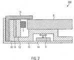
- Fig. 2 illustrates the cross section 200 of edge type LED TV backlight unit provided with piezoelectric cooler mounted over the heat sink 10, according to an embodiment of the present invention.
- the edge type LED TV backlight unit comprises of a LED bar 7 that is fixed on to a PCB 12.
- the PCB 12 is attached to the heat sink 10 using a double-sided adhesive material, i.e. thermal interface material (TIM) 11.
- TIM thermal interface material
- the heat sink 10 is covered with a middle frame 15 and a metal back cover 13.
- the LED bar 7 generates the heat and flows into the PCB 12.
- the PCB 12 spreads the heat into heatsink 10 and to a double-sided adhesive material, i.e. thermal interface material (TIM) 11.
- TIM 11 connects the LED bar/light array 7 to the heatsink 10.
- the heat transferred in a path to reach ambient by the middle frame 15, then the metal back cover 13. Further, the heat spreads to the optical components 8 by radiation of the LED bar7 and the heatsink 10.
- the piezoelectric cooler14 is stationed at the midst of arch-like structure of the heatsink 10.
- the airflow 9 generated by the piezoelectric cooler 14 is distributed to the heatsink 10, which is the main component to exert the heat caused by LED 7.
- the vibration at the piezoelectric materials 3 may prolong/shorten the membrane to collect/diffuse air.
- Manipulating the frequency of voltage applied to the piezoelectric cooler 14 can modify the air that is generated by piezoelectric cooler 14.
- the exerted air on heat sink 10 can reduce the temperature of the heatsink 10 by transferring the heat to nearby air molecules. Thus reduction in the total heat occurs. Considering that the total heat created by LED bar 7 is constant, the reduced heat creates drop at LED's junction and solder temperature.
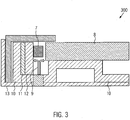
- Fig. 3 illustrates the cross section 300 of edge type LED TV backlight unit provided with piezoelectric cooler placed directly near to the LED bar 7, according to an embodiment of the present invention.
- the more effective usage of piezoelectric cooler14 to cool the LED bar 7 is placing the synthetic jet 14 directly near to the heat source of the display device.
- the cooling of the BLU and electronic boards of the display device is attained by acquiring forced air flow 9 from the synthetic jet 14 due to simultaneous compression and tension of the piezoelectric material 3 by applying AC/DC voltage to the piezoelectric material 3.
- the total airflow 9 is exerted on the LED bar7 to decrease the LED's solder and junction temperature.
- the air molecules from the synthetic jet 14 are transported to directly hit on the LED bar 7, which is the only heat source at the backlight unit (BLU).
- Fig. 4 illustrates the probable locations 400 of the piezoelectric coolerin the heat sink 10 of the LED TV backlight unit, according to an embodiment of the present invention.
- the synthetic jet 14 can be stationed above the heat sink 10 that is provided for dissipating heat from the heat source by means of forced airflow. That is for an edge type a LED display device, the synthetic jet 14 can also be mounted over the heat sink 10.
- the synthetic jet 14 can be placed at different locations as illustrated at 17 (16 & 18) of the heat sink 10. According to the requirement, the synthetic jet 14 can be placed at different locations as posed at the middle position of the heat sink 10 and two-side position (16 & 18) of the heat sink 10. Further, the synthetic jet 14 can also be placed near to the heat source at a bottom cover of a metal cover of the BLU of the display device.
- Fig. 5 illustrates the top view 500 of vertical edge type backlighting unit in the LED TV provided with the piezoelectric cooler, according to an embodiment of the present invention.
- the LED bars7 are stationed vertically at the right side.
- the synthetic jet 14 is placed at the bottom side of the metal back cover 13 to create a turbulent air flow 9 to decrease the temperature of heatsink 10 and the LED bar 7.
- Fig. 6A illustrates the top view 600A of direct type LED TV backlight unit provided with piezoelectric cooler placed directly near to the LED bar 7, according to an embodiment of the present invention.
- the top view of the direct type LED TV backlight unit shows the plurality of LED bar 7 that is placed horizontally on the PCB 21.
- a reflector film 20 covers the base of whole arrangement.
- a metal back cover 22 covers the reflector film 20.
- Fig. 6B illustrates the cross section 600B of direct type LED TV backlight unit provided with piezoelectric cooler placed directly near to the LED bar 7, according to an embodiment of the present invention.
- the LED bar 7 is placed vertically or horizontally on the PCB 21.
- the LED bar 7 is covered with a lens 23 and surrounded by the reflector film 20.
- the whole set up is covered by a metal back cover 22.
- the piezoelectric cooler 14 is placed just at the bottom of the PCB21.
- the airflow 9 is targeted to cool down the PCB 21 and the LED bar 7.
- the PCBs 21 are placed into a slit at the direct type backlight unit.
- the synthetic jet 14 is placed inside the slit along with the PCB 21.
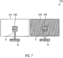
- Fig. 7 illustrates the piezoelectric cooler location 700 on the display's drivers of the display devices, according to another embodiment of the present invention.
- the display drivers include a main board 25A and a power board 24A.
- the plurality of heat sources of the display drivers includes a plurality of ICs (24B & 25B ICs of the power board and the main board) on electronic boards and other optical components 8 and/or mechanical components.
- the piezoelectric cooler/ synthetic jet 14 is provided for cooling the heat sources of the display drivers.
- the synthetic jet 14 is consturcted by placing two piezoelectric material 3 sandwiched between a rubber/metal cascade and form a thin chamber with an orifice 4 at one end and a vacuum silicon structure 1 at another end.
- the display drivers are attached to the back cover metal with screws to prevent the board components no to touch the metal back cover 13.
- the levitation about 5 or 6mm for boards gives enough room to install the piezoelectric cooler at the bottom side of display driver.
- the synthetic jet 14 with 1 mm thickness can fit in.
- the air flow 9 that is created can easily be directed to the desired display drivers' component.
- Fig. 8 illustrates a perspective view 800 of flip-chip packages provided for edge type LED TV BLU, according to an embodiment of the present invention.
- the synthetic jet 14 gives beneficial results as being used along with flip-chip packages 27 at the edge type backlighting systems.
- the flip-chip packages 27 are mounted over the PCB with the dampads 26.
- the dampads 26 are opto-mechanical components.
- the dampads 26 contains slits that are provided for directing the compressed air from the synthetic jet 14, on to the flip-chip packages 27.
- Fig. 9a and 9b illustrates a top view 900a and side view 900b of flip-chip packages provided for edge type LED TV BLU, according to an embodiment of the present invention.
- the figure 9a and 9b depicts the top and side view of the flip-chip packages 27 incorporated in the BLU.
- the present invention refers to a system for cooling backlight units and electronic boards of a display device.
- the system for cooling backlight units and electronic boards of a display device comprises of a plurality of heat sources of the display devices and at least a piezoelectric cooler / synthetic jet 14.
- the plurality of heat sources of the display devices includes a plurality of LED bar 7 in the backlight unit (BLU), a plurality of ICs on electronic boards and other optical component 8 and mechanical components.
- the synthetic jet 14 is provided for cooling the heat sources of the display devices. The appropriate placement of the synthetic jet 14 provides an efficient cooling compared all other cooling system. Hence, The synthetic jet 14 is stationed directly near to the heat source for cooling the backlight units and electronic boards of the display device.
Landscapes
- Engineering & Computer Science (AREA)
- Microelectronics & Electronic Packaging (AREA)
- Physics & Mathematics (AREA)
- Thermal Sciences (AREA)
- Liquid Crystal (AREA)
- Planar Illumination Modules (AREA)
- Devices For Indicating Variable Information By Combining Individual Elements (AREA)
- Arrangement Of Elements, Cooling, Sealing, Or The Like Of Lighting Devices (AREA)
Abstract
Description
- This invention refers to a system for cooling backlight units and electronic boards of a display device according to claim 1 and a system for cooling display drivers of a display device according to
claim 7. - TV manufactures market drives the LED TV makers to create and design slimmer mechanics with novel design.The miniaturization of volumes, smart features and enhanced higher luminance, poses thermal originated issues in backlight and in power/main boards. Gaining higher luminance from LED chips and higher functioning CPUs bring forth the rise in chip power. The rise in chip power of advanced electronics applications requires compact and efficient solutions. Conventional cooling techniques cannot meet the next generation cooling needs. Therefore, attention has been turned to novel cooling techniques.
- Specifically, two different types of BLU in LED/LCD display devices are available now in the market that includes a direct type and an edge type. The edge type display devices are further classified in to horizontal edge type and vertical edge type display device. Cooling techniques adapted for these display device includes passive cooling that is natural cooling and another one is active cooling that is forced cooling. Some drawbacks are exist when passive cooling is utilized. The main drawback is mechanical constraints. That is the shape of heatsink affects the whole system's thickness. Considering the thickness of LED bar is 0.75mm and thermal interface material (TIM) is 0.2mm and LED is 0.8mm.The tight placement limits the heatsink mechanical constraints. For direct type BLU, wide angle lens are utilised to decrease the number of LEDs in BLU and also to reduce the cost. As a consequence, the power consumption of induvidual LED incresed to achieve the light output targets for BLU. Therefore, increasing the power consumption of the LEDs also causes the local thermal hotspots need to be cooled by using active cooling methods. This cooling method will provide the reduction LEDs counts in direct type BLU and the more reliable system for direct type BLU. Mostly heatsink is not enough to effectively dissipate the heat through the system. So it limits the current and voltage that is applied to LED packages and electronic units. For instance, the reduction of the current may be essential to decrease the LED junction temperature of the backlighting system. But this decreases the total light output of back light unit (BLU). Further,the heat dissipation is limited based on material.The conductivity of material that is used as heatsink defines the resistivity value for heatsink. For efficient dissipation of heat, and to utilize high power LEDs the heat dissipating material that is frankly the heatsink must be replaced.
- Usually active cooling techniques are incorporated in the display device to get better efficiency. For this type of cooling, a fan is mounted behind the backlight unit's (BLU) back cover metalto dissipate heat. But in this also some limitations are there that includes requirement for high power consumption, size is too big for using in tight back light unit (BLU) system. Further, the efficiency is also limited according to the placement, fan geometry and so on.
- In the prior art
KR20040052173 (A - The subject-matter of
KR20040052173 (A - It is therefore the object of the present invention to provide a system for cooling backlight units and electronic boards of a display device, in particular a piezoelectric cooler assembly/system for cooling backlight units and ICs on electronic boards of the LED/LCD display devices.
- The before mentioned object is solved by providing a system for cooling backlight units and electronic boards of a display device according to claim 1. The system for cooling backlight units and electronic boards of a display device comprises of a plurality of heat sources of the display devices and at least a piezoelectric cooler. The piezo electric cooler can also be referred herein as synthetic jet. The plurality of heat sources of the display devices includes a plurality of LED bar in the backlight unit (BLU), a plurality of ICs on electronic boards and other optical and mechanical components. Further, the synthetic jetis provided for cooling the heat sources of the display devices.The synthetic jet is constructed by placing two piezoelectric material sandwiched between a rubber/metal cascade and form a thin chamber with an orifice at one end and a vacuum silicon structure at another end.
- Further embodiments of the invention are specified in the dependent claims.
- According to an embodiment, the placement of the synthetic jet provides an efficient cooling compared to all other cooling system. Accordingly, the synthetic jet is stationed directly near to the heat source for cooling the backlight units and electronic boards of the display device. The cooling of the display device is attained by acquiring forced air flow from the synthetic jet due to simultaneous compression and tension of the piezoelectric material by applying AC/DC voltage to the piezoelectric material.
- This solution is beneficial since the size of the cooler is very thin and efficient cooling can be achieved. Therefore, the synthetic jet(piezoelectric cooler) is placed near to the heat source directly.
- Further, the before mentioned object is solved by providing a system for cooling display drivers of a display device according to claim 7.The system for cooling display drivers of a display device comprises of a plurality of heat sources of the display drivers and at least a piezoelectric cooler. The piezo electric cooler can also be referred herein as synthetic jet-The display drivers include a main board and a power board. The plurality of heat sources of the display drivers includes a plurality of ICs on electronic boards and other optical and/or mechanical components. Further, the piezoelectric cooler/ synthetic jet is provided for cooling the heat sources of the display drivers.
- According to another embodiment,the synthetic jet is stationed directly near to the heat source of the display drivers for cooling the display drivers of the display device. The cooling of the display driversis attained by acquiring forced air flow from the synthetic jet due to simultaneous compression and tension of the piezoelectric material by applying AC/DC voltage to the piezoelectric material.
- Further preferred embodiments are subject matter of dependent claims and/or of the following specification parts.
- According to a preferred embodiment of the present invention, the synthetic jet is stationed above a heat sink that is provided for dissipating heat from the heat source by means of forced airflow.That is for an edge type a LED display device, the synthetic jet can also be mounted over and on the heat sink. The synthetic jet can be placed at either middle or each side of the heat sink. According to the requirement, synthetic jet can be placed at different locations that include positions between two-side of the heat sink. Further, the synthetic jet can also be placed near to the heat source at a bottom reservoir of a metal cover of the direct type BLU of the display device. Additionally the synthetic jet gives beneficial results as being used with the flip chip packages at edge type backlighting systems. The flipchip packages are mounted over the PCB with the dampads which are opto-mechanical components. The slits at the dampad geometry directs the compressed air which is produced by synthetic jet, on to the flip-chip packages.
- These features are beneficial since changing a frequency of the applied voltage to the piezoelectric material varies a velocity of the airflow generated by the synthetic jet.
- According to another embodiment of the present invention, the display drivers can also cooled directly by adjusting a velocity of the air flow generated by the synthetic jet is varied by changing a frequency of the applied voltage to the piezoelectric material.
- The aforementioned object is also solved by providing a piezoelectric cooler assembly/system for cooling backlight units and ICs on electronic boards of the LED/LCD display devicesaccording to claim 1 and 7.
- Further benefits, goals and features of the present invention will be described by the following specification of the attached figures, in which components of the invention are exemplarily illustrated. Components of the devices and method according to the inventions, which match at least essentially with respect to their function can be marked with the same reference sign, wherein such components do not have to be marked or described in all figures.
- The invention is just exemplarily described with respect to the attached figures in the following.
-
- Fig. 1A
- illustrates an exemplarypiezoelectric cooler or synthetic jet in expansion or ingestion mode of operation, according to the present invention;
- Fig. 1B
- illustrates the exemplary piezoelectric cooler or synthetic jet in compression or expulsion mode of operation, according to the present invention;
- Fig. 2
- illustrates the cross section of edge type LED TV backlight unit provided with piezoelectric cooler mounted over the heat sink, according to an embodiment of the present invention;
- Fig.3
- illustrates the cross section of edge type LED TV backlight unit provided with piezoelectric cooler placed directly near to the LED bar, according to an embodiment of the present invention;
- Fig. 4
- illustrates the probable locations of the piezoelectric cooler in the heat sink of the LED TV backlight unit, according to an embodiment of the present invention;
- Fig. 5
- illustrates the top view of vertical edge type backlighting unit in the LED TV provided with the piezoelectric cooler, according to an embodiment of the present invention;
- Fig. 6A
- illustrates the top view of direct type LED TV backlight unit provided with piezoelectric cooler placed directly near to the LED bar, according to an embodiment of the present invention;
- Fig. 6B
- illustrates the cross section of direct type LED TV backlight unit provided with piezoelectric cooler placed directly near to the LED bar, according to an embodiment of the present invention;
- Fig. 7
- illustrates the piezoelectric cooler location on the display's drivers of the display devices, according to another embodiment of the present invention;
- Fig. 8
- illustrates a perspective view of flip-chip packages provided for edge type LED TV BLU, according to an embodiment of the present invention;
- Fig. 9a
- illustrates a top view of flip-chip packages provided for edge type LED TV BLU, according to an embodiment of the present invention; and
- Fig. 9b
- illustrates a side view of flip-chip packages provided for edge type LED TV BLU, according to an embodiment of the present invention.
-
Fig. 1A illustrates a piezoelectric cooler 100A or synthetic jet in expansion or ingestion mode of operation, according to the present invention. The piezoelectric embodiment coolers are utilized for forced air-cooling for the electronic devices. The piezoelectric cooler is consturcted by placing twopiezoelectric material 3 sandwiched between a rubber/metal 1 cascade and form a thin chamber with anorifice 4 at one end and a vacuum siliconrubber 1 or silicon structure 1 at another end. Thepiezoelectric material 3 is placed over a thin disk orblade 2. A silicon rubber 1 or an adhesive silicon material 1 separates the disk 2.The whole cooling system is a few millimeters thick and occupies very small space. Thepiezoelectric material 3 oscillates with variable frequency related to the AC/DC voltage applied on them. Due to that, the air velocity and amount of the air exerted from cooler can be adjusted. During expansion, thepiezoelectric material 3 is stretched out and gets expanded due to the application of electrical power. At that instant, outside air may flow inside 5 the expanded thin chamber. -
Fig. 1B illustrates the exemplary piezoelectric cooler 100B orsynthetic jet 14 in compression or expulsion mode of operation, according to the present invention. During compression, thepiezoelectric material 3 is compressed inside and blows out the air 6 (air flow outside) occupied inside the chamber due to the change in frequency of the applied electrical power. At that instant, the air present inside the chamber may blow out forcibly to the components present near to thesynthetic jet 14. That is how the cooling of the BLU and display drivers of the display devices is attained by simultaneous compression and tension of thepiezoelectric material 3 by applying AC/DC voltage to thepiezoelectric material 3. -
Fig. 2 illustrates thecross section 200 of edge type LED TV backlight unit provided with piezoelectric cooler mounted over theheat sink 10, according to an embodiment of the present invention.The edge type LED TV backlight unit comprises of aLED bar 7 that is fixed on to aPCB 12. ThePCB 12 is attached to theheat sink 10 using a double-sided adhesive material, i.e. thermal interface material (TIM) 11. Theheat sink 10 is covered with amiddle frame 15 and ametal back cover 13. - The
LED bar 7 generates the heat and flows into thePCB 12. ThePCB 12 spreads the heat intoheatsink 10 and to a double-sided adhesive material, i.e. thermal interface material (TIM) 11. TheTIM 11 connects the LED bar/light array 7 to theheatsink 10. The heat transferred in a path to reach ambient by themiddle frame 15, then themetal back cover 13. Further, the heat spreads to theoptical components 8 by radiation of the LED bar7 and theheatsink 10. The piezoelectric cooler14 is stationed at the midst of arch-like structure of theheatsink 10. Theairflow 9 generated by thepiezoelectric cooler 14 is distributed to theheatsink 10, which is the main component to exert the heat caused byLED 7. The vibration at thepiezoelectric materials 3 may prolong/shorten the membrane to collect/diffuse air. Manipulating the frequency of voltage applied to thepiezoelectric cooler 14 can modify the air that is generated bypiezoelectric cooler 14. The exerted air onheat sink 10 can reduce the temperature of theheatsink 10 by transferring the heat to nearby air molecules. Thus reduction in the total heat occurs. Considering that the total heat created byLED bar 7 is constant, the reduced heat creates drop at LED's junction and solder temperature. -
Fig. 3 illustrates thecross section 300 of edge type LED TV backlight unit provided with piezoelectric cooler placed directly near to theLED bar 7, according to an embodiment of the present invention. The more effective usage of piezoelectric cooler14 to cool theLED bar 7 is placing thesynthetic jet 14 directly near to the heat source of the display device. The cooling of the BLU and electronic boards of the display device is attained by acquiring forcedair flow 9 from thesynthetic jet 14 due to simultaneous compression and tension of thepiezoelectric material 3 by applying AC/DC voltage to thepiezoelectric material 3. In this schema, thetotal airflow 9 is exerted on the LED bar7 to decrease the LED's solder and junction temperature. The air molecules from thesynthetic jet 14 are transported to directly hit on theLED bar 7, which is the only heat source at the backlight unit (BLU). -
Fig. 4 illustrates theprobable locations 400 of the piezoelectric coolerin theheat sink 10 of the LED TV backlight unit, according to an embodiment of the present invention. Thesynthetic jet 14 can be stationed above theheat sink 10 that is provided for dissipating heat from the heat source by means of forced airflow. That is for an edge type a LED display device, thesynthetic jet 14 can also be mounted over theheat sink 10. Thesynthetic jet 14 can be placed at different locations as illustrated at 17 (16 & 18) of theheat sink 10. According to the requirement, thesynthetic jet 14 can be placed at different locations as posed at the middle position of theheat sink 10 and two-side position (16 & 18) of theheat sink 10. Further, thesynthetic jet 14 can also be placed near to the heat source at a bottom cover of a metal cover of the BLU of the display device. -
Fig. 5 illustrates thetop view 500 of vertical edge type backlighting unit in the LED TV provided with the piezoelectric cooler, according to an embodiment of the present invention. At vertical type of edge type back light units, the LED bars7 are stationed vertically at the right side. In this type, thesynthetic jet 14 is placed at the bottom side of themetal back cover 13 to create aturbulent air flow 9 to decrease the temperature ofheatsink 10 and theLED bar 7. -
Fig. 6A illustrates thetop view 600A of direct type LED TV backlight unit provided with piezoelectric cooler placed directly near to theLED bar 7, according to an embodiment of the present invention.The top view of the direct type LED TV backlight unit shows the plurality ofLED bar 7 that is placed horizontally on thePCB 21. Areflector film 20 covers the base of whole arrangement. Ametal back cover 22 covers thereflector film 20. -
Fig. 6B illustrates thecross section 600B of direct type LED TV backlight unit provided with piezoelectric cooler placed directly near to theLED bar 7, according to an embodiment of the present invention.At the direct type LED TV backlight unit, theLED bar 7 is placed vertically or horizontally on thePCB 21. TheLED bar 7 is covered with alens 23 and surrounded by thereflector film 20. The whole set up is covered by ametal back cover 22. Thepiezoelectric cooler 14 is placed just at the bottom of the PCB21.Theairflow 9 is targeted to cool down thePCB 21 and theLED bar 7. ThePCBs 21 are placed into a slit at the direct type backlight unit. Thesynthetic jet 14 is placed inside the slit along with thePCB 21. -
Fig. 7 illustrates the piezoelectriccooler location 700 on the display's drivers of the display devices, according to another embodiment of the present invention. The display drivers include amain board 25A and apower board 24A. The plurality of heat sources of the display drivers includes a plurality of ICs (24B & 25B ICs of the power board and the main board) on electronic boards and otheroptical components 8 and/or mechanical components. Further, the piezoelectric cooler/synthetic jet 14 is provided for cooling the heat sources of the display drivers.Thesynthetic jet 14 is consturcted by placing twopiezoelectric material 3 sandwiched between a rubber/metal cascade and form a thin chamber with anorifice 4 at one end and a vacuum silicon structure 1 at another end. The display drivers are attached to the back cover metal with screws to prevent the board components no to touch themetal back cover 13. The levitation about 5 or 6mm for boards gives enough room to install the piezoelectric cooler at the bottom side of display driver. Thesynthetic jet 14 with 1 mm thickness can fit in. Theair flow 9 that is created can easily be directed to the desired display drivers' component. -
Fig. 8 illustrates aperspective view 800 of flip-chip packages provided for edge type LED TV BLU, according to an embodiment of the present invention. Thesynthetic jet 14 gives beneficial results as being used along with flip-chip packages 27 at the edge type backlighting systems. The flip-chip packages 27 are mounted over the PCB with thedampads 26. Thedampads 26 are opto-mechanical components. Thedampads 26 contains slits that are provided for directing the compressed air from thesynthetic jet 14, on to the flip-chip packages 27. -
Fig. 9a and 9b illustrates a top view 900a and side view 900b of flip-chip packages provided for edge type LED TV BLU, according to an embodiment of the present invention. Thefigure 9a and 9b depicts the top and side view of the flip-chip packages 27 incorporated in the BLU. - Thus, the present invention refers to a system for cooling backlight units and electronic boards of a display device. The system for cooling backlight units and electronic boards of a display device comprises of a plurality of heat sources of the display devices and at least a piezoelectric cooler /
synthetic jet 14. The plurality of heat sources of the display devices includes a plurality ofLED bar 7 in the backlight unit (BLU), a plurality of ICs on electronic boards and otheroptical component 8 and mechanical components. Further, thesynthetic jet 14 is provided for cooling the heat sources of the display devices. The appropriate placement of thesynthetic jet 14 provides an efficient cooling compared all other cooling system. Hence, Thesynthetic jet 14 is stationed directly near to the heat source for cooling the backlight units and electronic boards of the display device. -
- 1
- silicon rubber
- 2
- blade or disk
- 3
- piezoelectric material
- 4
- an orifice
- 5
- air flow to the thin chamber
- 6
- air flow from the thin chamber
- 7
- LED bar / LED
- 8
- optical components
- 9
- air flow
- 10
- heat sink
- 11
- thermal interface material (TIM)
- 12
- PCB for edge type BLU
- 13
- metal back cover for edge type BLU
- 14
- synthetic jet or piezoelectric cooler
- 15
- middle frame
- 16
- one side position of the heat sink
- 17
- middle position of the heat sink
- 18
- another side position of the heat sink
- 19
- PCB and LED bar inside the metal back cover
- 20
- reflector film
- 21
- PCB for the direct type BLU
- 22
- metal back cover for the direct type BLU
- 23
- lens covered over the LED
- 24A
- power board of the display drivers
- 24B
- IC for the power board
- 25A
- main board of the display drivers
- 25B
- IC for the main board
- 26
- dampads
- 27
- flip-chip packages or flip-chip
- 100
- an exemplary piezoelectric cooler or synthetic jet in expansion or ingestion mode of operation
- 100A
- an exemplary piezoelectric cooler or synthetic jet in compression or expulsion mode of operation
- 200
- a cross section of edge type LED TV backlight unit provided with piezoelectric cooler mounted over the heat sink
- 300
- a cross section of edge type LED TV backlight unit provided with piezoelectric cooler placed directly near to the LED bar
- 400
- probable locations of the piezoelectric cooler in the heat sink of the LED TV backlight unit
- 500
- the top view of vertical edge type backlighting unit in the LED TV provided with the piezoelectric cooler
- 600A
- the top view of direct type LED TV backlight unit provided with piezoelectric cooler placed directly near to the LED bar
- 600B
- the cross section of direct type LED TV backlight unit provided with piezoelectric cooler placed directly near to the LED bar
- 700
- the piezoelectric cooler locationon the display's drivers of the display devices
- 800
- perspective view of flip-chip packages provided for edge type LED TV BLU
- 900a
- top view of flip-chip packages provided for edge type LED TV BLU
- 900b
- side view of flip-chip packages provided for edge type LED TV BLU
Claims (10)
- A system for cooling backlight units and electronic boards of a display device comprises of:a plurality of heat sources of the display devices;wherein the plurality of heat sources of the display devices includes a plurality of LED bar (7) in the backlight unit (BLU), a plurality of ICs on electronic boards and other optical components (8) and/or mechanical components;wherein the system further comprises at least a synthetic jet (14) for cooling the heat sources of the display devices;wherein the synthetic jet (14) includes two piezoelectric material (3) sandwiched between a rubber/metal cascade (2) and form a thin chamber with an orifice (4) at one end and a vacuum silicon structure (1) at another end;characterized in that the synthetic jet (14) is stationed directly near to the heat source for cooling the backlight units and electronic boards of the display device; andwherein the cooling of the display device attained by acquiring forced air flow (9) from the synthetic jet (14) due to simultaneous compression and tension of the piezoelectric material (3) by applying AC/DC voltage to the piezoelectric material (3).
- The system of claim 1, wherein the synthetic jet (14) is stationed above a heat sink (10) provided for dissipating heat from the heat source by means of forced air flow (9).
- The system of claim 2, wherein at least one synthetic jet (14) is placed at either middle (17) or each side (16&18) of the heat sink (10).
- The system of claim 2, wherein the synthetic jet (14) is placed at the middle (17) and each side (16 & 18) of the heat sink (10) or is placed at any place of the heat sink (10).
- The system of claim 1, wherein the synthetic jet (14) is placed near to the heat source at bottom cover of a metal back cover (13) of the BLU of the display device.
- The system of claim 1, wherein a velocity of the air flow (9) generated by the synthetic jet (14) is varied by changing a frequency of the applied voltage to the piezoelectric material (3).
- The system of claim 1, wherein the synthetic jets (14) utilizes flip-chip packages (27) for transferring compressed air from synthetic jet (14) to flow through slits provided at dampads (26) geometry; and wherein the flip-chips (27) are mounted over a PCB with the dampads (26).
- A system for cooling display drivers of a display device comprises of:a plurality of heat sources of the display drivers;wherein the display drivers include a main board (25A) and a power board (24A);wherein the plurality of heat sources of the display drivers includes a plurality of ICs (24B & 25B) on electronic boards and other optical component (8) and/or mechanical components;wherein the system further comprises at least a piezoelectric cooler/ synthetic jet (14) for cooling the heat sources of the display drivers;wherein the synthetic jet (14) includes two piezoelectric material (3) sandwiched between a rubber/metal (2) cascade and form a thin chamber with an orifice (4) at one end and a vacuum silicone structure (1) at another end;characterized in thatthe synthetic jet (14) is stationed directly near to the heat source of the display drivers for cooling the display drivers of the display device; andwherein the cooling of the display drivers attained by acquiring forced air flow (9) from the synthetic jet (14) due to simultaneous compression and tension of the piezoelectric material (3) by applying AC/DC voltage to the piezoelectric material (3).
- The system of claim 8, wherein the synthetic jet (14) is stationed above a heat sink (10) provided for dissipating heat from the heat source by means of forced air flow (9).
- The system of claim 8, wherein a velocity of the airflow (9) generated by the synthetic jet (14) is varied by changing a frequency of the applied voltage to the piezoelectric material (3).
Priority Applications (1)
| Application Number | Priority Date | Filing Date | Title |
|---|---|---|---|
| EP17172699.5A EP3407691B1 (en) | 2017-05-24 | 2017-05-24 | System for cooling backlight units and electronic boards of a display device |
Applications Claiming Priority (1)
| Application Number | Priority Date | Filing Date | Title |
|---|---|---|---|
| EP17172699.5A EP3407691B1 (en) | 2017-05-24 | 2017-05-24 | System for cooling backlight units and electronic boards of a display device |
Publications (2)
| Publication Number | Publication Date |
|---|---|
| EP3407691A1 true EP3407691A1 (en) | 2018-11-28 |
| EP3407691B1 EP3407691B1 (en) | 2019-12-18 |
Family
ID=59030758
Family Applications (1)
| Application Number | Title | Priority Date | Filing Date |
|---|---|---|---|
| EP17172699.5A Active EP3407691B1 (en) | 2017-05-24 | 2017-05-24 | System for cooling backlight units and electronic boards of a display device |
Country Status (1)
| Country | Link |
|---|---|
| EP (1) | EP3407691B1 (en) |
Cited By (1)
| Publication number | Priority date | Publication date | Assignee | Title |
|---|---|---|---|---|
| US20220225536A1 (en) * | 2021-06-25 | 2022-07-14 | The Intel Corporation | Thermal management systems for electronic devices and related methods |
Citations (6)
| Publication number | Priority date | Publication date | Assignee | Title |
|---|---|---|---|---|
| US6123145A (en) * | 1995-06-12 | 2000-09-26 | Georgia Tech Research Corporation | Synthetic jet actuators for cooling heated bodies and environments |
| KR20040052173A (en) | 2002-12-14 | 2004-06-19 | 엘지전자 주식회사 | back cover structure of refrigeration fan |
| WO2010029485A1 (en) * | 2008-09-12 | 2010-03-18 | Koninklijke Philips Electronics N.V. | A device provided with a gap-like space and a synthetic jet generator coupled thereto |
| US20110037937A1 (en) * | 2008-05-27 | 2011-02-17 | Shenzhen New Supper-Bright Lcd Display Co.,Ltd. | Lcd apparatus with heat dissipation arrangements |
| US20150108899A1 (en) * | 2013-10-22 | 2015-04-23 | General Electric Company | Power circuitry for a synthetic jet of a cooling system |
| US20160095255A1 (en) * | 2014-09-29 | 2016-03-31 | Ice Computer, Inc. | Thermal piezoelectric apparatus |
-
2017
- 2017-05-24 EP EP17172699.5A patent/EP3407691B1/en active Active
Patent Citations (6)
| Publication number | Priority date | Publication date | Assignee | Title |
|---|---|---|---|---|
| US6123145A (en) * | 1995-06-12 | 2000-09-26 | Georgia Tech Research Corporation | Synthetic jet actuators for cooling heated bodies and environments |
| KR20040052173A (en) | 2002-12-14 | 2004-06-19 | 엘지전자 주식회사 | back cover structure of refrigeration fan |
| US20110037937A1 (en) * | 2008-05-27 | 2011-02-17 | Shenzhen New Supper-Bright Lcd Display Co.,Ltd. | Lcd apparatus with heat dissipation arrangements |
| WO2010029485A1 (en) * | 2008-09-12 | 2010-03-18 | Koninklijke Philips Electronics N.V. | A device provided with a gap-like space and a synthetic jet generator coupled thereto |
| US20150108899A1 (en) * | 2013-10-22 | 2015-04-23 | General Electric Company | Power circuitry for a synthetic jet of a cooling system |
| US20160095255A1 (en) * | 2014-09-29 | 2016-03-31 | Ice Computer, Inc. | Thermal piezoelectric apparatus |
Non-Patent Citations (1)
| Title |
|---|
| MONGIA R K ET AL: "Heat Transfer Enhancement Using Synthetic Jets for Cooling in Low Form Factor Electronics in Presence of Mean Flow", ELECTRONICS PACKAGING TECHNOLOGY CONFERENCE, 2007. EPTC 2007. 9TH, IEEE, PISCATAWAY, NJ, USA, 10 December 2007 (2007-12-10), pages 830 - 835, XP031238139, ISBN: 978-1-4244-1324-9 * |
Cited By (2)
| Publication number | Priority date | Publication date | Assignee | Title |
|---|---|---|---|---|
| US20220225536A1 (en) * | 2021-06-25 | 2022-07-14 | The Intel Corporation | Thermal management systems for electronic devices and related methods |
| US12414261B2 (en) * | 2021-06-25 | 2025-09-09 | Intel Corporation | Thermal management systems for electronic devices and related methods |
Also Published As
| Publication number | Publication date |
|---|---|
| EP3407691B1 (en) | 2019-12-18 |
Similar Documents
| Publication | Publication Date | Title |
|---|---|---|
| US10969615B2 (en) | Electronic display assembly | |
| KR102081928B1 (en) | Digital signage | |
| CN110389474B (en) | Liquid crystal display device | |
| US7212404B2 (en) | Integrated heat sink device | |
| US7606027B2 (en) | Electronic apparatus cooling structure | |
| US7794116B2 (en) | LED lamp with a heat dissipation device | |
| US6906922B2 (en) | Integrated heat-dissipating module | |
| US20090109621A1 (en) | Heat dissipating device | |
| JP2005265922A (en) | Plasma display device | |
| US20130083483A1 (en) | Heat dissipation device and electronic device using same | |
| CN113056176A (en) | Heat dissipation framework and display device | |
| US9743551B2 (en) | Thermal piezoelectric apparatus | |
| CN112243334A (en) | Heat radiation structure of heating component | |
| CN101142866A (en) | Heat absorbing member, cooling device and electronic equipment | |
| EP2608259A2 (en) | Cooling device and electronic apparatus using same | |
| EP3407691B1 (en) | System for cooling backlight units and electronic boards of a display device | |
| KR20070002494A (en) | Backlight unit | |
| JP2008098432A (en) | Electronic component heat dissipation device | |
| US20080068807A1 (en) | Heat-dissipating device for back light source for flat panel display | |
| TWI286721B (en) | Heat-dissipating apparatus for a back light module of a liquid crystal display | |
| EP1916648A1 (en) | Luminous display panel | |
| US7002795B2 (en) | Low noise heatsink | |
| JP2009238785A (en) | Electronic circuit module and projector | |
| CN102819300A (en) | Heat sink and electronic device structure | |
| KR20230153053A (en) | Cooling structure for image photographing apparatus |
Legal Events
| Date | Code | Title | Description |
|---|---|---|---|
| PUAI | Public reference made under article 153(3) epc to a published international application that has entered the european phase |
Free format text: ORIGINAL CODE: 0009012 |
|
| STAA | Information on the status of an ep patent application or granted ep patent |
Free format text: STATUS: THE APPLICATION HAS BEEN PUBLISHED |
|
| AK | Designated contracting states |
Kind code of ref document: A1 Designated state(s): AL AT BE BG CH CY CZ DE DK EE ES FI FR GB GR HR HU IE IS IT LI LT LU LV MC MK MT NL NO PL PT RO RS SE SI SK SM TR |
|
| AX | Request for extension of the european patent |
Extension state: BA ME |
|
| STAA | Information on the status of an ep patent application or granted ep patent |
Free format text: STATUS: REQUEST FOR EXAMINATION WAS MADE |
|
| 17P | Request for examination filed |
Effective date: 20190520 |
|
| RBV | Designated contracting states (corrected) |
Designated state(s): AL AT BE BG CH CY CZ DE DK EE ES FI FR GB GR HR HU IE IS IT LI LT LU LV MC MK MT NL NO PL PT RO RS SE SI SK SM TR |
|
| GRAP | Despatch of communication of intention to grant a patent |
Free format text: ORIGINAL CODE: EPIDOSNIGR1 |
|
| STAA | Information on the status of an ep patent application or granted ep patent |
Free format text: STATUS: GRANT OF PATENT IS INTENDED |
|
| INTG | Intention to grant announced |
Effective date: 20190712 |
|
| GRAS | Grant fee paid |
Free format text: ORIGINAL CODE: EPIDOSNIGR3 |
|
| GRAA | (expected) grant |
Free format text: ORIGINAL CODE: 0009210 |
|
| STAA | Information on the status of an ep patent application or granted ep patent |
Free format text: STATUS: THE PATENT HAS BEEN GRANTED |
|
| AK | Designated contracting states |
Kind code of ref document: B1 Designated state(s): AL AT BE BG CH CY CZ DE DK EE ES FI FR GB GR HR HU IE IS IT LI LT LU LV MC MK MT NL NO PL PT RO RS SE SI SK SM TR |
|
| REG | Reference to a national code |
Ref country code: CH Ref legal event code: EP |
|
| REG | Reference to a national code |
Ref country code: IE Ref legal event code: FG4D |
|
| REG | Reference to a national code |
Ref country code: DE Ref legal event code: R096 Ref document number: 602017009759 Country of ref document: DE |
|
| REG | Reference to a national code |
Ref country code: AT Ref legal event code: REF Ref document number: 1216067 Country of ref document: AT Kind code of ref document: T Effective date: 20200115 |
|
| REG | Reference to a national code |
Ref country code: NL Ref legal event code: MP Effective date: 20191218 |
|
| PG25 | Lapsed in a contracting state [announced via postgrant information from national office to epo] |
Ref country code: LV Free format text: LAPSE BECAUSE OF FAILURE TO SUBMIT A TRANSLATION OF THE DESCRIPTION OR TO PAY THE FEE WITHIN THE PRESCRIBED TIME-LIMIT Effective date: 20191218 Ref country code: SE Free format text: LAPSE BECAUSE OF FAILURE TO SUBMIT A TRANSLATION OF THE DESCRIPTION OR TO PAY THE FEE WITHIN THE PRESCRIBED TIME-LIMIT Effective date: 20191218 Ref country code: FI Free format text: LAPSE BECAUSE OF FAILURE TO SUBMIT A TRANSLATION OF THE DESCRIPTION OR TO PAY THE FEE WITHIN THE PRESCRIBED TIME-LIMIT Effective date: 20191218 Ref country code: BG Free format text: LAPSE BECAUSE OF FAILURE TO SUBMIT A TRANSLATION OF THE DESCRIPTION OR TO PAY THE FEE WITHIN THE PRESCRIBED TIME-LIMIT Effective date: 20200318 Ref country code: NO Free format text: LAPSE BECAUSE OF FAILURE TO SUBMIT A TRANSLATION OF THE DESCRIPTION OR TO PAY THE FEE WITHIN THE PRESCRIBED TIME-LIMIT Effective date: 20200318 Ref country code: GR Free format text: LAPSE BECAUSE OF FAILURE TO SUBMIT A TRANSLATION OF THE DESCRIPTION OR TO PAY THE FEE WITHIN THE PRESCRIBED TIME-LIMIT Effective date: 20200319 Ref country code: LT Free format text: LAPSE BECAUSE OF FAILURE TO SUBMIT A TRANSLATION OF THE DESCRIPTION OR TO PAY THE FEE WITHIN THE PRESCRIBED TIME-LIMIT Effective date: 20191218 |
|
| REG | Reference to a national code |
Ref country code: LT Ref legal event code: MG4D |
|
| PG25 | Lapsed in a contracting state [announced via postgrant information from national office to epo] |
Ref country code: HR Free format text: LAPSE BECAUSE OF FAILURE TO SUBMIT A TRANSLATION OF THE DESCRIPTION OR TO PAY THE FEE WITHIN THE PRESCRIBED TIME-LIMIT Effective date: 20191218 Ref country code: RS Free format text: LAPSE BECAUSE OF FAILURE TO SUBMIT A TRANSLATION OF THE DESCRIPTION OR TO PAY THE FEE WITHIN THE PRESCRIBED TIME-LIMIT Effective date: 20191218 |
|
| PG25 | Lapsed in a contracting state [announced via postgrant information from national office to epo] |
Ref country code: AL Free format text: LAPSE BECAUSE OF FAILURE TO SUBMIT A TRANSLATION OF THE DESCRIPTION OR TO PAY THE FEE WITHIN THE PRESCRIBED TIME-LIMIT Effective date: 20191218 |
|
| PG25 | Lapsed in a contracting state [announced via postgrant information from national office to epo] |
Ref country code: EE Free format text: LAPSE BECAUSE OF FAILURE TO SUBMIT A TRANSLATION OF THE DESCRIPTION OR TO PAY THE FEE WITHIN THE PRESCRIBED TIME-LIMIT Effective date: 20191218 Ref country code: CZ Free format text: LAPSE BECAUSE OF FAILURE TO SUBMIT A TRANSLATION OF THE DESCRIPTION OR TO PAY THE FEE WITHIN THE PRESCRIBED TIME-LIMIT Effective date: 20191218 Ref country code: RO Free format text: LAPSE BECAUSE OF FAILURE TO SUBMIT A TRANSLATION OF THE DESCRIPTION OR TO PAY THE FEE WITHIN THE PRESCRIBED TIME-LIMIT Effective date: 20191218 Ref country code: NL Free format text: LAPSE BECAUSE OF FAILURE TO SUBMIT A TRANSLATION OF THE DESCRIPTION OR TO PAY THE FEE WITHIN THE PRESCRIBED TIME-LIMIT Effective date: 20191218 Ref country code: PT Free format text: LAPSE BECAUSE OF FAILURE TO SUBMIT A TRANSLATION OF THE DESCRIPTION OR TO PAY THE FEE WITHIN THE PRESCRIBED TIME-LIMIT Effective date: 20200513 |
|
| PG25 | Lapsed in a contracting state [announced via postgrant information from national office to epo] |
Ref country code: SM Free format text: LAPSE BECAUSE OF FAILURE TO SUBMIT A TRANSLATION OF THE DESCRIPTION OR TO PAY THE FEE WITHIN THE PRESCRIBED TIME-LIMIT Effective date: 20191218 Ref country code: IS Free format text: LAPSE BECAUSE OF FAILURE TO SUBMIT A TRANSLATION OF THE DESCRIPTION OR TO PAY THE FEE WITHIN THE PRESCRIBED TIME-LIMIT Effective date: 20200418 Ref country code: SK Free format text: LAPSE BECAUSE OF FAILURE TO SUBMIT A TRANSLATION OF THE DESCRIPTION OR TO PAY THE FEE WITHIN THE PRESCRIBED TIME-LIMIT Effective date: 20191218 |
|
| REG | Reference to a national code |
Ref country code: DE Ref legal event code: R097 Ref document number: 602017009759 Country of ref document: DE |
|
| REG | Reference to a national code |
Ref country code: AT Ref legal event code: MK05 Ref document number: 1216067 Country of ref document: AT Kind code of ref document: T Effective date: 20191218 |
|
| PLBE | No opposition filed within time limit |
Free format text: ORIGINAL CODE: 0009261 |
|
| STAA | Information on the status of an ep patent application or granted ep patent |
Free format text: STATUS: NO OPPOSITION FILED WITHIN TIME LIMIT |
|
| PG25 | Lapsed in a contracting state [announced via postgrant information from national office to epo] |
Ref country code: ES Free format text: LAPSE BECAUSE OF FAILURE TO SUBMIT A TRANSLATION OF THE DESCRIPTION OR TO PAY THE FEE WITHIN THE PRESCRIBED TIME-LIMIT Effective date: 20191218 Ref country code: DK Free format text: LAPSE BECAUSE OF FAILURE TO SUBMIT A TRANSLATION OF THE DESCRIPTION OR TO PAY THE FEE WITHIN THE PRESCRIBED TIME-LIMIT Effective date: 20191218 |
|
| 26N | No opposition filed |
Effective date: 20200921 |
|
| PG25 | Lapsed in a contracting state [announced via postgrant information from national office to epo] |
Ref country code: SI Free format text: LAPSE BECAUSE OF FAILURE TO SUBMIT A TRANSLATION OF THE DESCRIPTION OR TO PAY THE FEE WITHIN THE PRESCRIBED TIME-LIMIT Effective date: 20191218 Ref country code: AT Free format text: LAPSE BECAUSE OF FAILURE TO SUBMIT A TRANSLATION OF THE DESCRIPTION OR TO PAY THE FEE WITHIN THE PRESCRIBED TIME-LIMIT Effective date: 20191218 |
|
| PG25 | Lapsed in a contracting state [announced via postgrant information from national office to epo] |
Ref country code: IT Free format text: LAPSE BECAUSE OF FAILURE TO SUBMIT A TRANSLATION OF THE DESCRIPTION OR TO PAY THE FEE WITHIN THE PRESCRIBED TIME-LIMIT Effective date: 20191218 Ref country code: LI Free format text: LAPSE BECAUSE OF NON-PAYMENT OF DUE FEES Effective date: 20200531 Ref country code: CH Free format text: LAPSE BECAUSE OF NON-PAYMENT OF DUE FEES Effective date: 20200531 Ref country code: MC Free format text: LAPSE BECAUSE OF FAILURE TO SUBMIT A TRANSLATION OF THE DESCRIPTION OR TO PAY THE FEE WITHIN THE PRESCRIBED TIME-LIMIT Effective date: 20191218 |
|
| PG25 | Lapsed in a contracting state [announced via postgrant information from national office to epo] |
Ref country code: PL Free format text: LAPSE BECAUSE OF FAILURE TO SUBMIT A TRANSLATION OF THE DESCRIPTION OR TO PAY THE FEE WITHIN THE PRESCRIBED TIME-LIMIT Effective date: 20191218 |
|
| REG | Reference to a national code |
Ref country code: BE Ref legal event code: MM Effective date: 20200531 |
|
| PG25 | Lapsed in a contracting state [announced via postgrant information from national office to epo] |
Ref country code: LU Free format text: LAPSE BECAUSE OF NON-PAYMENT OF DUE FEES Effective date: 20200524 |
|
| PG25 | Lapsed in a contracting state [announced via postgrant information from national office to epo] |
Ref country code: FR Free format text: LAPSE BECAUSE OF NON-PAYMENT OF DUE FEES Effective date: 20200531 Ref country code: IE Free format text: LAPSE BECAUSE OF NON-PAYMENT OF DUE FEES Effective date: 20200524 |
|
| PG25 | Lapsed in a contracting state [announced via postgrant information from national office to epo] |
Ref country code: BE Free format text: LAPSE BECAUSE OF NON-PAYMENT OF DUE FEES Effective date: 20200531 |
|
| PG25 | Lapsed in a contracting state [announced via postgrant information from national office to epo] |
Ref country code: MT Free format text: LAPSE BECAUSE OF FAILURE TO SUBMIT A TRANSLATION OF THE DESCRIPTION OR TO PAY THE FEE WITHIN THE PRESCRIBED TIME-LIMIT Effective date: 20191218 Ref country code: CY Free format text: LAPSE BECAUSE OF FAILURE TO SUBMIT A TRANSLATION OF THE DESCRIPTION OR TO PAY THE FEE WITHIN THE PRESCRIBED TIME-LIMIT Effective date: 20191218 |
|
| PG25 | Lapsed in a contracting state [announced via postgrant information from national office to epo] |
Ref country code: MK Free format text: LAPSE BECAUSE OF FAILURE TO SUBMIT A TRANSLATION OF THE DESCRIPTION OR TO PAY THE FEE WITHIN THE PRESCRIBED TIME-LIMIT Effective date: 20191218 |
|
| PGFP | Annual fee paid to national office [announced via postgrant information from national office to epo] |
Ref country code: GB Payment date: 20260526 Year of fee payment: 10 |
|
| PGFP | Annual fee paid to national office [announced via postgrant information from national office to epo] |
Ref country code: DE Payment date: 20260625 Year of fee payment: 10 |
|
| PGFP | Annual fee paid to national office [announced via postgrant information from national office to epo] |
Ref country code: TR Payment date: 20260522 Year of fee payment: 10 |