EP3407675B1 - Wideband remote unit for distributed antenna system - Google Patents
Wideband remote unit for distributed antenna system Download PDFInfo
- Publication number
- EP3407675B1 EP3407675B1 EP18183359.1A EP18183359A EP3407675B1 EP 3407675 B1 EP3407675 B1 EP 3407675B1 EP 18183359 A EP18183359 A EP 18183359A EP 3407675 B1 EP3407675 B1 EP 3407675B1
- Authority
- EP
- European Patent Office
- Prior art keywords
- signal
- uplink
- downlink
- wideband
- remote unit
- Prior art date
- Legal status (The legal status is an assumption and is not a legal conclusion. Google has not performed a legal analysis and makes no representation as to the accuracy of the status listed.)
- Active
Links
- 238000004891 communication Methods 0.000 claims description 38
- 238000000034 method Methods 0.000 claims description 25
- 238000005070 sampling Methods 0.000 claims description 24
- 238000002955 isolation Methods 0.000 claims description 22
- 230000000116 mitigating effect Effects 0.000 claims description 18
- 239000002131 composite material Substances 0.000 claims description 12
- 230000008569 process Effects 0.000 claims description 8
- 238000001914 filtration Methods 0.000 claims description 6
- 230000001360 synchronised effect Effects 0.000 claims 1
- 238000012545 processing Methods 0.000 description 49
- 230000000875 corresponding effect Effects 0.000 description 24
- 238000006243 chemical reaction Methods 0.000 description 17
- 238000010586 diagram Methods 0.000 description 16
- 230000005540 biological transmission Effects 0.000 description 14
- 230000002452 interceptive effect Effects 0.000 description 12
- 230000004044 response Effects 0.000 description 11
- 238000001228 spectrum Methods 0.000 description 10
- 238000013519 translation Methods 0.000 description 8
- 230000002829 reductive effect Effects 0.000 description 5
- 238000004519 manufacturing process Methods 0.000 description 4
- 230000003044 adaptive effect Effects 0.000 description 3
- 230000003321 amplification Effects 0.000 description 2
- 230000002238 attenuated effect Effects 0.000 description 2
- 230000006870 function Effects 0.000 description 2
- 238000003199 nucleic acid amplification method Methods 0.000 description 2
- 230000003287 optical effect Effects 0.000 description 2
- 239000013307 optical fiber Substances 0.000 description 2
- IRLPACMLTUPBCL-KQYNXXCUSA-N 5'-adenylyl sulfate Chemical compound C1=NC=2C(N)=NC=NC=2N1[C@@H]1O[C@H](COP(O)(=O)OS(O)(=O)=O)[C@@H](O)[C@H]1O IRLPACMLTUPBCL-KQYNXXCUSA-N 0.000 description 1
- RYGMFSIKBFXOCR-UHFFFAOYSA-N Copper Chemical compound [Cu] RYGMFSIKBFXOCR-UHFFFAOYSA-N 0.000 description 1
- 238000007792 addition Methods 0.000 description 1
- 230000004075 alteration Effects 0.000 description 1
- 230000008901 benefit Effects 0.000 description 1
- 230000008859 change Effects 0.000 description 1
- 229910052802 copper Inorganic materials 0.000 description 1
- 239000010949 copper Substances 0.000 description 1
- 230000002596 correlated effect Effects 0.000 description 1
- 230000008878 coupling Effects 0.000 description 1
- 238000010168 coupling process Methods 0.000 description 1
- 238000005859 coupling reaction Methods 0.000 description 1
- 230000001419 dependent effect Effects 0.000 description 1
- 238000001514 detection method Methods 0.000 description 1
- 238000005516 engineering process Methods 0.000 description 1
- 238000009432 framing Methods 0.000 description 1
- 230000006872 improvement Effects 0.000 description 1
- 238000003780 insertion Methods 0.000 description 1
- 230000037431 insertion Effects 0.000 description 1
- 238000009434 installation Methods 0.000 description 1
- 230000000670 limiting effect Effects 0.000 description 1
- 230000007774 longterm Effects 0.000 description 1
- 238000005259 measurement Methods 0.000 description 1
- 238000010295 mobile communication Methods 0.000 description 1
- 238000012986 modification Methods 0.000 description 1
- 230000004048 modification Effects 0.000 description 1
- 230000000737 periodic effect Effects 0.000 description 1
- 230000009467 reduction Effects 0.000 description 1
- 230000001172 regenerating effect Effects 0.000 description 1
- 238000012552 review Methods 0.000 description 1
- URWAJWIAIPFPJE-YFMIWBNJSA-N sisomycin Chemical compound O1C[C@@](O)(C)[C@H](NC)[C@@H](O)[C@H]1O[C@@H]1[C@@H](O)[C@H](O[C@@H]2[C@@H](CC=C(CN)O2)N)[C@@H](N)C[C@H]1N URWAJWIAIPFPJE-YFMIWBNJSA-N 0.000 description 1
- 239000000779 smoke Substances 0.000 description 1
- 230000003068 static effect Effects 0.000 description 1
- 238000010897 surface acoustic wave method Methods 0.000 description 1
- 239000002699 waste material Substances 0.000 description 1
Images


Classifications
-
- H—ELECTRICITY
- H04—ELECTRIC COMMUNICATION TECHNIQUE
- H04B—TRANSMISSION
- H04B15/00—Suppression or limitation of noise or interference
- H04B15/02—Reducing interference from electric apparatus by means located at or near the interfering apparatus
-
- H—ELECTRICITY
- H04—ELECTRIC COMMUNICATION TECHNIQUE
- H04W—WIRELESS COMMUNICATION NETWORKS
- H04W88/00—Devices specially adapted for wireless communication networks, e.g. terminals, base stations or access point devices
- H04W88/08—Access point devices
- H04W88/085—Access point devices with remote components
-
- H—ELECTRICITY
- H04—ELECTRIC COMMUNICATION TECHNIQUE
- H04B—TRANSMISSION
- H04B1/00—Details of transmission systems, not covered by a single one of groups H04B3/00 - H04B13/00; Details of transmission systems not characterised by the medium used for transmission
- H04B1/38—Transceivers, i.e. devices in which transmitter and receiver form a structural unit and in which at least one part is used for functions of transmitting and receiving
- H04B1/40—Circuits
- H04B1/50—Circuits using different frequencies for the two directions of communication
- H04B1/52—Hybrid arrangements, i.e. arrangements for transition from single-path two-direction transmission to single-direction transmission on each of two paths or vice versa
- H04B1/525—Hybrid arrangements, i.e. arrangements for transition from single-path two-direction transmission to single-direction transmission on each of two paths or vice versa with means for reducing leakage of transmitter signal into the receiver
Definitions
- the present disclosure relates generally to telecommunication systems and more particularly (although not necessarily exclusively) to wideband remote units for distributed antenna systems.
- a distributed antenna system can be used to provide wireless communications coverage in a variety of environments, particularly in large structures such as office buildings, convention halls, airports, stadiums, and the like.
- a DAS can include one or more head-end units (e.g., master units) that are communicatively coupled to one or more base stations.
- a DAS can also include multiple remote units that are communicatively coupled to each head-end unit.
- the remote units each of which can include one or more transceivers and antennas, can be distributed across a coverage area.
- the remote units can transmit the downlink signals to mobile phones or other terminal devices within coverage areas serviced by the remote units.
- Remote units for a DAS may use large amounts of electrical power and may have a large physical size. For example, the power requirements and size of a remote unit may be increased if the remote unit includes extensive analog circuitry for downconverting or otherwise modifying received analog signals prior to generating a digitized representation of communication channels of interest.
- a remote unit may include a first RF transceiver with associated analog circuitry for communicating signals in an Advanced Mobile Phone System (“AMPS”) band, a second RF transceiver with associated analog circuitry for communicating signals in a Personal Communications Service (“PCS”) band, and a third RF transceiver with associated analog circuitry for communicating signals in an Advanced Wireless Services (“AWS”) band, etc.
- AMPS Advanced Mobile Phone System
- PCS Personal Communications Service
- AWS Advanced Wireless Services
- One or more of the power requirements and physical size of a remote unit may increase costs associated with manufacturing or installing the remote unit.
- a distributed antenna system comprising a host unit and at least one remote antenna unit that is communicatively coupled to the host unit is disclosed in US Patent Application US 2012/3229523A1 .
- a distributed antenna system having a downlink communication path, an uplink communication path, and a non-duplexer isolator sub-system is disclosed in US Patent Application US 2012/0309328A1 .
- DAS distributed antenna system
- a method can involve a wideband remote unit receiving, via an uplink path, wideband signals that include an uplink RF signal and a leaked downlink RF signal.
- the uplink RF signal can have an uplink signal power at or near a noise level of the wideband remote unit.
- the leaked downlink RF signal can have a downlink signal power greater than the uplink signal power.
- the leaked downlink RF signal can be a downlink RF signal that is transmitted by the remote unit and received by an antenna of the remote unit.
- the method can also involve converting, by the wideband remote unit, the received wideband signals to digital RF signals that represent the uplink signal and the downlink signal.
- the method can also involve transmitting, by the wideband remote unit, the digital RF signals to a unit of the DAS for transmission to a base station by the unit.
- a wideband remote unit can include one or more antennas and an analog-to-digital converter ("ADC").
- An antenna of the wideband remote unit can receive wideband signals.
- the wideband signals can include an uplink RF signal and a leaked downlink RF signal.
- the uplink RF signal can have an uplink signal power at or near a noise level of the wideband remote unit.
- the leaked downlink RF signal can have a downlink signal power greater than the uplink signal power.
- the ADC can convert the received wideband signals to digital RF signals representing both the uplink signal and the downlink signal.
- the wideband remote unit can transmit the digital RF signals to a unit of a DAS for transmission to a base station.
- a DAS includes one or more wideband remote units and a unit that can communicate with a base station.
- the wideband remote unit can receive wideband signals.
- the wideband signals can include an uplink RF signal and a leaked downlink RF signal.
- the uplink RF signal can have an uplink signal power at or near a noise level of the wideband remote unit.
- the leaked downlink RF signal can have a downlink signal power greater than the uplink signal power.
- the wideband remote unit can convert the received wideband signals to digital RF signals representing the uplink signal and the downlink signal.
- the unit can receive the digital RF signals from the remote unit.
- the unit can transmit an uplink signal corresponding to one of the digital RF signals to a base station.
- the unit can mitigate another digital RF signal corresponding to the leaked downlink RF signal.
- a method comprises: receiving, via an uplink path of a wideband remote unit of a distributed antenna system, wideband signals comprising an uplink RF signal and a leaked downlink RF signal, the uplink RF signal having an uplink signal power and the leaked downlink RF signal having a downlink signal power greater than the uplink signal power, wherein the leaked downlink RF signal is from a downlink RF signal transmitted by the wideband remote unit; converting, by the wideband remote unit, the received wideband signals to a first digital RF signal that represents the uplink signal and to a second digital RF signal that represents the downlink signal; and transmitting, by the wideband remote unit, the first digital RF signal and the second digital RF signal to a unit of the distributed antenna system in communication with a base station.
- the method further comprises providing, via a downlink path of the wideband remote unit, the downlink RF signal to an antenna that transmits the downlink RF signal, wherein the downlink path is coupled via a splitter-combiner to the uplink path the antenna.
- the method further comprises: transmitting, by the unit, an uplink signal to the base station, wherein the uplink signal corresponds to the first digital RF signal; and mitigating, by the unit, the second digital RF signal corresponding to the leaked downlink RF signal.
- mitigating the second digital RF signal comprises at least one of: filtering the second digital RF signal from a combined uplink signal generated from the first digital RF signal; cancelling the second digital RF signal from the combined uplink signal; or attenuating the second digital RF signal.
- mitigating the second digital RF signal comprises: correlating a downlink signal traversing the downlink path with a signal component traversing the uplink path; generating a cancellation signal corresponding to the second digital RF signal based on correlating the downlink signal traversing the downlink path with the signal component traversing the uplink path; and combining the cancellation signal with a combined uplink signal generated from the first digital RF signal.
- the uplink signal power is at a thermal noise level associated with the wideband remote unit
- the method further comprises configuring an analog-to-digital converter of the wideband remote unit with a dynamic range having a minimum value corresponding to the thermal noise level and a maximum value corresponding to the downlink signal power.
- the method further comprises configuring the dynamic range based on a data rate for a digital communication link between the wideband remote unit and the unit.
- the downlink RF signal comprises a first multiple-input, multiple-output data stream received from the unit
- the method further comprises: transmitting, by an additional wideband remote unit of the distributed antenna system, an additional downlink RF signal comprising a second multiple-input, multiple-output data stream; receiving, by the additional wideband remote unit, an additional leaked downlink RF signal, wherein the additional leaked downlink RF signal is obtained from the additional downlink RF signal transmitted by the additional wideband remote unit; transmitting, by the additional wideband remote unit, a third digital RF signal to the unit, wherein the third digital RF signal is generated from the additional leaked downlink RF signal; and mitigating, by the unit, the second digital RF signal and the third digital RF signal.
- a wideband remote unit comprises: an antenna configured for receiving wideband signals comprising an uplink RF signal and a leaked downlink RF signal, the uplink RF signal having an uplink signal power and the leaked downlink RF signal having a downlink signal power greater than the uplink signal power, wherein the leaked downlink RF signal is from a downlink RF signal transmitted by the wideband remote unit; and an analog-to-digital converter configured for converting the received wideband signals to a first digital RF signal that represents the uplink signal and to a second digital RF signal that represents the downlink signal, wherein the wideband remote unit is configured for transmitting the first and second digital RF signals to a unit of a distributed antenna system that is communicatively coupled to a base station.
- the wideband remote unit further comprises a downlink path configured for providing the downlink RF signal to the antenna and an uplink path comprising the analog-to-digital converter, wherein the uplink path is communicatively coupled to the downlink path via a splitter-combiner of the wideband remote unit.
- the analog-to-digital converter of the wideband remote unit has a dynamic range having a minimum value corresponding to a thermal noise level associated with the wideband remote unit and a maximum value corresponding to the downlink signal power.
- the dynamic range is based on a data rate for a digital communication link between the wideband remote unit and the unit.
- the analog-to-digital converter of the wideband remote unit has a sampling rate corresponding to a maximum RF frequency of the wideband signals and the data rate for the digital communication link.
- a distributed antenna system comprises: a wideband remote unit configured for: receiving wideband signals comprising an uplink RF signal and a leaked downlink RF signal, the uplink RF signal having an uplink signal power and the leaked downlink RF signal having a downlink signal power greater than the uplink signal power, wherein the leaked downlink RF signal is from a downlink RF signal transmitted by the wideband remote unit, converting the received wideband signals to a first digital RF signal that represents the uplink signal and a second digital RF signal that represents the downlink signal, and transmitting the first and second digital RF signals to a unit; and the unit configured for: transmitting an uplink signal to a base station, wherein the uplink signal corresponds to the first digital RF signal; and mitigating the second digital RF signal corresponding to the leaked downlink RF signal.
- the wideband remote unit comprises a downlink path configured for providing the downlink RF signal to an antenna of the wideband remote unit, wherein the downlink path is coupled via a splitter-combiner to the antenna and an uplink path configured for receiving the wideband signals.
- the unit comprises a non-duplexer isolation sub-system configured for mitigating the second digital RF signal.
- the wideband remote unit comprises an analog-to-digital converter with a dynamic range having a minimum value corresponding to a thermal noise level associated with the wideband remote unit and a maximum value corresponding to the downlink signal power.
- the dynamic range is based on a data rate for a digital communication link between the wideband remote unit and the unit.
- the analog-to-digital converter of the wideband remote unit has a sampling rate corresponding to a maximum RF frequency of the wideband signals and the data rate for the digital communication link.
- the downlink RF signal comprises a first multiple-input, multiple-output data stream received from the unit
- the distributed antenna system further comprises: an additional wideband remote unit configured for: transmitting an additional downlink RF signal comprising a second multiple-input, multiple-output data stream, receiving an additional leaked downlink RF signal, wherein the additional leaked downlink RF signal is obtained from the additional downlink RF signal transmitted by the additional wideband remote unit, and transmitting a third digital RF signal to the unit, wherein the third digital RF signal is generated from the additional leaked downlink RF signal, wherein the unit is further configured for mitigating the third digital RF signal.
- a wideband remote unit can include any remote unit for a DAS that is configured to generate digitized RF uplink signals from analog uplink RF signals that are received at frequencies over a wideband spectrum (e.g., 200 MHz to 3 GHz).
- a wideband spectrum can include a spectrum including frequency bands associated with multiple types of telecommunication providers (e.g., code division multiple access (“CDMA”) systems, Long Term Evolution (“LTE”) systems, etc.).
- CDMA code division multiple access
- LTE Long Term Evolution
- the wideband remote unit can transmit the digitized RF uplink signals to a head-end unit or other suitable unit of the DAS.
- the wideband remote unit can perform some analog and signal processing.
- the wideband remote unit can be limited to transmitting signals of interest, receiving signals of interest, and transporting the signals to a central unit in a DAS for processing (e.g., a head-end unit, an expansion unit, etc.).
- the wideband remote unit can be implemented in a manner that allows the wideband remote unit to have one or more of a smaller size or lower power requirements as compared to other remote units.
- the wideband remote unit can be implemented without frequency translation circuitry.
- the wideband remote unit can include a high-speed analog-to-digital converter ("ADC") that can sample signals at a sufficiently high sampling rate that allows the wideband remote unit to omit down-conversion circuitry for converting RF signals to intermediate frequency (“IF”) signals.
- ADC analog-to-digital converter
- the wideband remote unit can be implemented without isolation circuitry for isolating uplink signals from downlink signals.
- an ADC of the wideband remote unit can have a sufficiently wide dynamic range to digitally represent low-power uplink signals in the uplink path and high-power downlink signals that leak to the uplink path.
- Digitally representing signals over a wide dynamic range can allow a head-end unit or other suitable high-power unit in the DAS to attenuate leaked downlink signals in the uplink path.
- Using a head-end unit or other suitable high-power unit in the DAS rather than the remote unit to attenuate leaked downlink signals in the uplink path can limit the amount of circuitry required by the remote unit.
- the wideband remote unit can be used without specifically designing or otherwise configuring the wideband remote unit for operation with a given telecommunication standard, frequency band, or other telecommunication technology.
- the wideband remote unit can include a wideband receiver that can be used to receive signals in multiple frequency bands.
- FIG. 1 is a block diagram depicting an example of a DAS 102 that includes wideband remote units 108a-n according to one aspect.
- the DAS 102 can communicate signals between one or more base stations 101 or other transceiver devices (e.g., repeaters) and terminal devices in one or more coverage zones serviced by the DAS 102.
- Terminal devices can be electronic devices used to communicate one or more of voice and data via a telecommunication system, such as (but not limited to) mobile phones.
- the DAS 102 can include one or more units 104.
- a unit 104 include a head-end unit, a base station router, or other suitable unit that can communicate with a base station.
- the unit 104 can be a head-end unit or other suitable unit that can communicate with one or more base stations 101 or other transceiver devices in communication with the DAS 102.
- a head-end unit can include, for example, an optical transceiver that transmits optical signals to the wideband remote units 108a-n.
- the head-end unit or other suitable unit 104 can communicate with remote units 108a-n in different coverage zones of the same DAS 102.
- the unit 104 can be included in a base station router or other suitable device that can communicate signals between one or more base stations 101 and one or more head-end units. In additional or alternative aspects, the unit 104 can be included in an extension unit or other suitable unit that can communicate signals between one or more head-end units and the wideband remote units 108a-n.
- the DAS 102 can also include remote units 108a-n having respective wideband RF transceivers 110a-n.
- Each of the wideband remote units 108a-n can include transceiver devices that can include or be communicatively coupled to one or more antennas.
- One example of a remote unit is a universal access point.
- a DAS 102 can include any number of units 104 and any number of remote units 108a-n.
- the DAS 102 can communicate signals to and from terminal devices via the unit 104 and the wideband remote units 108a-n that service one or more coverage zones.
- the unit 104 can be communicatively coupled with the base station 101 and the wideband remote units 108a-n in any suitable manner.
- Communicatively coupling devices in a DAS 102 or other telecommunication system can involve establishing, maintaining, or otherwise using a communication link (e.g., a cable, an optical fiber, a wireless link, etc.) to communicate information between the devices.
- a communication link e.g., a cable, an optical fiber, a wireless link, etc.
- Any suitable types of communication links can be used in the DAS 102.
- a suitable communication link can be a wired connection or a wireless connection.
- Types of wired connections can include, for example, a connection via a copper cable, an optical fiber, or another suitable communication medium.
- Types of wireless connections can include, for example, a wireless RF communication link or a microwave link.
- the type of communication link between the base station 101 and the unit 104 can be the same as or different from the type of communication link between the unit 104 and the wideband remote units 108a-n.
- the unit 104 can provide downlink signals from the base station 101 to the wideband remote units 108a-n and receive uplink signals from the wideband remote units 108a-n to be provided to the base station 101.
- Downlink signals can include signals provided from the base station 101 and transmitted by the wideband remote units 108a-n in coverage zones.
- Uplink signals can include signals transmitted by terminal devices and received by the wideband remote units 108a-n.
- the wideband remote units 108a-n can provide signal coverage in one or more coverage zones. Providing signal coverage in the coverage zones can include wirelessly transmitting downlink signals received from the unit 104 to terminal devices in the coverage zones. Providing signal coverage in the coverage zones can also include wirelessly receiving uplink signals from the mobile communication devices or other terminal devices in the coverage zones.
- the wideband remote units 108a-n can transmit the uplink signals to the unit 104.
- the unit 104 can transmit the uplink signals to the base station 101.
- FIG. 1 depicts direct links between the unit 104 and the wideband remote units 108a-n, other implementations are possible.
- the unit 104 can be communicatively coupled to the wideband remote units 108a-n via one or more extension units or other intermediate devices.
- the unit 104 can combine uplink transmissions received from some or all of the wideband remote units 108a-n into a combined uplink signal, such as a composite signal.
- a transmitter of the unit 104 can transmit the combined uplink signal to an uplink receiver of the base station 101.
- the unit 104 can use the processing module 106 to combine uplink transmissions received from the wideband remote units 108an.
- the processing module 106 can include one or more devices configured to select uplink signals for a combination, programming instructions executable by a processor to select uplink signals for a combination, or any suitable combination thereof.
- the wideband remote units 108a-n can operate using a reduced amount of RF circuitry as compared to conventional remote units. Reducing the amount of circuitry in a remote unit can reduce one or more of the size of the remote unit and the costs associated with manufacturing or installing the remote unit.
- the amount of circuitry used in a remote unit can be reduced by, for example, using a single RF transceiver that is configured for digitizing signals having frequencies within large frequency bandwidths for digital transport to a unit 104 or other head-end unit.
- the amount of circuitry used in a wideband remote unit 108 can also be reduced by, for example, omitting RF signal processing components such as up-conversion components, down-conversion components, isolation devices, etc.
- FIG. 2 is a block diagram depicting an example of a wideband remote unit 108 according to one aspect.
- the wideband remote unit 108 can include an antenna 200, a multiple wideband RF transceivers 110, and a processing module 212.
- the multiple wideband RF transceivers 110 can include an uplink path 201 and a downlink path 203.
- the uplink path 201 can include a low-noise amplifier 204, an anti-aliasing filter 206, a variable gain device 208, and an ADC 210.
- the uplink path 201 can be limited to the devices depicted in FIG. 2 .
- the uplink path 201 can include additional devices other than those depicted in FIG. 2 .
- the downlink path 203 can include a digital-to-analog converter ("DAC") 214, an image filter 216, and a power amplifier 218.
- the downlink path 203 can be limited to the devices depicted in FIG. 2 .
- the downlink path 203 can include additional devices other than those depicted in FIG. 2 .
- one or more elements of the antenna 200 can receive uplink signals. Although a single antenna 200 is depicted for illustrative purposes, other implementations are possible. In some aspects, one or more antenna elements can be used for transmitting signals and one or more other antenna elements can be used for receiving signals. In other aspects, one or more antenna elements can be used for transmitting signals and receiving signals in a time-division multiplexed manner.
- a splitter-combiner 202 in the multiple wideband RF transceivers 110 can communicatively couple the downlink path 203 and the uplink path 201 to a common port that is communicatively coupled to the antenna 200.
- the splitter-combiner 202 can split downlink signals to be transmitted via the antenna 200 from uplink signals that are received via the antenna 200.
- the low-noise amplifier 204 can amplify the uplink signals to improve the signal-to-noise ratio of the received uplink signals.
- the anti-aliasing filter 206 can filter the received uplink signals to reduce or prevent aliasing. Aliasing can be caused by converting analog uplink signals to digital uplink signals using the ADC 210.
- the low-noise amplifier 204 can have a high dynamic range. The high dynamic range can compensate for limited attenuation from the downlink path 203.
- the anti-aliasing filter 206 in the uplink path 201 can reduce or prevent undesired signals from aliasing into desired Nyquist zones.
- An anti-aliasing filter 206 is a surface acoustic wave ("SAW') filter.
- a mixer or other demodulation device can be included in the uplink path 201.
- An example of a bandwidth that may be used by the anti-aliasing filter 206 is 75 MHz.
- the anti-aliasing filter 206 can be a low-pass filter with a cut-off frequency below 3.5 GHz, which is the limit of the Nyquist zone.
- the anti-aliasing filter 206 can use a 3.2 GHz sample rate and can have an RF input bandwidth between 30 MHz and 450 MHz.
- the anti-aliasing filter 206 can use a sample rate of up to 3 GHz and can have a 2.5 GHz input bandwidth.
- the frequency range from 700 MHz to 1 GHz can be sampled in the first Nyquist zone, and the frequency range from 1.7 GHz to 2.2 GHz can be sampled in the second Nyquist zone.
- the sample rate for the anti-aliasing filter 206 can be selected (e.g., 2.3 GHz) to avoid aliasing of the two frequency ranges onto the same frequency.
- the ADC 210 can convert the analog uplink signal to a digital uplink signal.
- the ADC 210 can digitize uplink signals in a manner that allows for the omission of frequency translation circuitry (e.g., down-conversion circuitry such as a mixer and local oscillator) from the uplink path 201.
- the ADC 210 can use a sampling rate suitable for sampling signals from a wideband spectrum.
- the ADC 210 may be configured to sample analog uplink RF signals at a sufficiently high sampling rate such that high-frequency signals in a wideband spectrum are sampled at a rate greater than or equal to a Nyquist rate (e.g., twice the frequency of the sampled analog signal).
- a wideband spectrum may include signals having frequencies up to 3.5 GHz, and the ADC 210 may use a sampling rate of 7 GHz or higher.
- a wideband spectrum can include a spectrum having frequency bands associated with multiple types of telecommunication providers.
- the wideband behavior of the remote unit 108 can involve the remote unit 108 being nonselective such that all RF bands within the frequency range of the remote unit 108 are processed.
- the remote unit 108 can be implemented without using dedicated filters to isolate one or more bands.
- the wideband behavior of the remote unit 108 can also involve the remote unit 108 processing both downlink and uplink frequencies rather than using one or more filters to select a downlink frequency band or uplink frequency band for processing.
- the ADC 210 can digitize uplink signals in a manner that allows for implementing the remote unit 108 without analog circuitry for isolating uplink signals from downlink signals.
- the ADC 210 can have a resolution that is suitable for digitizing signals within a wideband spectrum that have a wide range of signal powers.
- the wideband remote unit 108 may be implemented without a duplexer or other analog devices that isolate downlink signals transmitted to terminal devices by one or more elements of the antenna 200 from uplink signals received from terminal devices by one or more elements of the antenna 200.
- the absence of a duplexer or other analog isolation devices can allow the downlink signals transmitted by one or more elements of the antenna 200 to be received by one or more elements of the antenna 200 and provided to the uplink path 201 of the wideband remote unit 108. These downlink signals received by the antenna 200 may have a higher signal strength than uplink signals received from terminal devices.
- Using an ADC 210 with a sufficient resolution can allow one or more digital processing devices in one or more of the wideband remote unit 108 and the unit 104 to distinguish between low-power uplink signals and high-power uplink signals that both traverse the uplink path 201.
- the resolution of the ADC 210 can be expressed in a number of bits that correspond to a number of available signal power levels that can be digitally represented.
- an n-bit ADC 210 can be used to digitally represent 2 n signal power levels.
- the dynamic range of the ADC 210 (e.g., the range of signal power levels that can be digitally represented using the ADC 210) can correspond to number n of bits for the ADC 210 and the increment between the digitally represented power levels. For example, for an increment of m dB per bit, the dynamic range of an n-bit ADC 210 is n ⁇ m dB.
- a sufficiently wide dynamic range of the ADC 210 can allow the anti-aliasing filter 206 to digitize both uplink signals having low signal powers and downlink signals that may leak into the uplink path 201.
- One example of the ADC 210 is a delta-sigma ADC.
- the dynamic range for the ADC can be 6.02 dB ⁇ n + 1.76 dB.
- the sampling rate of the ADC 210, the number of bits used by the ADC 210 to express signal power levels, and a data rate of a communication link 220 from the wideband remote unit 108 to the unit 104 can be related.
- the product of the sampling rate of the ADC 210 and the number of bits used by the ADC 210 can be less than or equal to a data rate of a serial communication link 220 used to communicate digital uplink signals to the unit 104.
- the ADC 210 may sample values from an analog uplink signal at a rate of r samples per second.
- the ADC can encode each sampled value using n bits. Communicating n-bit samples at a rate of r samples per second can involve using a communication link 220 having a data rate of r ⁇ n bits per second.
- the following non-limiting example illustrates (without limitation) a sample configuration for the wideband remote unit 108.
- the wideband remote unit 108 may be used to receive uplink signals in frequency bands from 200 MHz to 3 GHz.
- the anti-aliasing filter 206 can have a low pass corner frequency of 3 GHz with a stop-band frequency of 4 GHz.
- the ADC 210 can be configured to digitally represent the bandwidth of 3.5 GHz that accounts for the uplink frequency bands and the stop-band frequency by using a sampling rate of at least 7 GHz (e.g., double the highest frequency of 3.5 GHz).
- the signal powers of uplink signals received by the wideband remote unit 108 may be as low as -105 dBm.
- the signal powers of downlink signals transmitted by the wideband remote unit 108 may be as high as +12 dBm.
- the range of signal powers for signals traversing the uplink path 201 e.g., low-power uplink signals, downlink signals received by one or more elements of the antenna 200
- the ADC 210 can use 20 bits (117 dB divided by 6 dB per bit) to digitally represent sampled signal power values of analog uplink RF signals.
- the data rate for a serial communication link 220 between the wideband remote unit 108 and the unit 104 can be at least 140 Gbps (the product of the 7-GHz sampling rate and the 20-bit digital value) in the uplink direction. In other cases, the data rate for the serial communication link 220 can be reduced further using filtering and sample rate conversion.
- the wideband remote unit 108 can receive digital downlink signals from the unit 104.
- a digital signal representing a downlink frequency band can be provided to a DAC 214 of the wideband remote unit 108 via a serial communication link from a unit 104.
- the digital downlink signals can be converted to analog RF downlink signals by the high-speed DAC 214.
- the DAC 214 can generate RF signals without performing frequency translation in the analog domain using frequency translation circuitry (e.g. up-conversion circuitry such as a mixer and local oscillator in the downlink path 203).
- frequency translation may be performed in the digital domain using high-speed digital circuitry in the DAC 214.
- frequency translation may be performed in the digital domain using a processing module 212.
- the image filter 216 can filter the RF downlink signals to remove images generated by the DAC 214.
- the DAC 214 may create images as a result of the sample-and-hold operation performed by the DAC 214.
- the image filter 216 that removes or reduces these images can be an image rejection analog filter in the downlink path 203.
- the RF downlink signals can be amplified by the power amplifier 218 for transmission to one or more terminal devices.
- the wideband remote unit 108 can include a single wideband RF transceiver 110 that is configured to receive and transmit signals at frequencies within all frequency bands of interest for a DAS 102.
- a wideband remote unit 108 can include multiple wideband RF transceivers 110. Each of the wideband RF transceivers 110 can receive and transmit signals at frequencies within a portion of the frequency bands of interest for a DAS 102.
- a first wideband RF transceiver in the wideband remote unit 108 can transmit or receive signals having frequencies in a frequency band of 200 MHz to 1 GHz
- a second wideband RF transceiver in the wideband remote unit 108 can transmit or receive signals having frequencies in a frequency band of 1 GHz to 2 GHz
- a third wideband RF transceiver in the wideband remote unit 108 can transmit or receive signals having frequencies in a frequency band of 2 GHz to 3 GHz.
- the wideband remote unit 108 can include simplified circuitry as compared to an RF transceiver of a conventional remote unit.
- the wideband remote unit 108 can omit circuitry used for frequency translation that would otherwise be performed in one or both of the uplink path 201 and the downlink path 203 (e.g., up-conversion components, down-conversion components, amplifiers used to compensate for loss introduced by frequency translation, etc.).
- conventional remote units of a DAS may include a large amount of RF, analog, and digital circuitry, such as a downlink path 203 and an uplink path 201 having multiple RF processing components.
- the downlink path 203 can include up-conversion circuitry (e.g., a local oscillator and a mixer) to up-convert downlink signals from IF to RF and a filter and amplifier following the up-conversion circuitry.
- the uplink path 201 can include a bandpass filter, down-conversion circuitry (e.g., a local oscillator and a mixer) to down-convert uplink signals from RF to IF, and one or more amplifiers following the down-conversion circuitry.
- the RF, analog, and digital circuitry of a conventional remote unit may use a large amount of power.
- the mixers in the uplink and downlink paths 203 can respectively attenuate uplink and downlink signals.
- the amplifiers following the mixers in the uplink and downlink paths 203 can compensate for the loss introduced by the mixers.
- Other RF signal processing components such as anti-aliasing filters, can be used to compensate for non-linear distortion of uplink and downlink signals introduced by the up-conversion and down-conversion circuitry.
- the use of the amplifiers and filters associated with up-conversion components and down-conversion components can increase one or more of the power used by a remote unit, the size of the remote unit, the costs associated with manufacturing or installing the remote unit, etc.
- the inclusion of the RF, analog, and digital circuitry may also increase the physical dimensions of the remote unit, thereby increasing the amount of space required to install the remote unit in a deployment environment (e.g., a building serviced using the DAS 102).
- the wideband remote unit 108 can be implemented without a duplexer.
- a conventional RF transceiver may include one or more duplexers for isolating a transmitter output (e.g., downlink signals) from a receiver input (e.g., uplink signals).
- the duplexer can allow frequencies within the downlink frequency band to be provided from the transmitter output to the antenna and can allow frequencies within the uplink frequency band to be provided from the antenna output to the receiver. Isolating a transmitter output from a receiver input can prevent downlink signals from interfering with uplink signals.
- the duplexer may introduce some amount of insertion loss, which can cause some of the power amplification from the power amplifier to be wasted. The waste of power amplification can reduce the efficiency of conventional remote units.
- FIG. 3 is a block diagram depicting an example of the processing module 212 of the wideband remote unit 108 according to one aspect.
- the processing module 212 can include one or more suitable processing devices that can be used to implement a digital processing section.
- the processing module 212 can perform one or more operations on downlink signals received from a unit 104.
- the processing module 212 can also perform one or more operations on uplink signals to be provided to the unit 104. Examples of a processing device include an application-specific integrated circuit ("ASIC"), a field-programmable gate array (“FPGA”), or another suitable processing device or suitable processing circuitry.
- ASIC application-specific integrated circuit
- FPGA field-programmable gate array
- the processing module 212 can include a parallel-serial converter 302, a framer-deframer 304, and a digital pre-distortion module 306.
- one or more of the parallel-serial converter 302, the framer-deframer 304, and the digital pre-distortion module 306 can include one or more hardware devices included in or communicatively coupled to a processing device of the processing module 212.
- one or more of the parallel-serial converter 302, the framer-deframer 304, and the digital pre-distortion module 306 can include program code stored in a memory device and executed by a processing device of the processing module 212.
- one or more of the parallel-serial converter 302, the framer-deframer 304, and the digital pre-distortion module 306 can be implemented using a combination of one or more hardware devices included in or communicatively coupled to a processing device of the processing module 212 and program code stored in a memory device and executed by a processing device of the processing module 212.
- the parallel-serial converter 302 can perform one or more operations to de-serialize a serial downlink data stream into multiple digital downlink signals to be provided to different downlink paths 203 of the wideband remote unit 108.
- the parallel-serial converter 302 can de-multiplex digital downlink signals from a common serial downlink data stream.
- the parallel-serial converter 302 can perform one or more operations to serialize parallel uplink signals into a common serialized uplink data stream to be provided to the unit 104.
- the parallel-serial converter 302 can combine parallel uplink digital signals received from multiple uplink signal paths of the remote 108 into a serialized uplink signals.
- the transport between the unit 104 and one or more of the ADC 210 and the DAC 214 can use an internal format for the ADC 210 and the DAC 214, which can be transported either as-is or with framing by the framer-deframer 304.
- the parallel-serial converter 302 can be omitted.
- a regenerating serial data link repeater can be included to restore the bits to meet the timing that is used by the DAC 214 or the unit 104.
- the framer-deframer 304 can de-frame digital downlink signals to obtain downlink payload data for transmission via the antenna 200.
- the framer-deframer 304 can frame digital uplink signals for transmission to the unit 104.
- the digital pre-distortion module 306 can pre-distort downlink signals prior to digital-to-analog conversion and transmission via the antenna 200. Pre-distorting downlink signals prior to transmission via the antenna 200 can reduce or prevent downlink intermodulation products from being generated in the downlink path 203.
- one or more components of the downlink path 203 or elsewhere in the remote unit 108 can include non-linearities that generate intermodulation products.
- the digital pre-distortion module 306 can pre-distort downlink signals in a manner that offsets or otherwise compensates for these non-linearities.
- Offsetting or otherwise compensating for these non-linearities can prevent intermodulation products from being transmitted by the remote unit 108 or reduce the intermodulation products received in the uplink path 201.
- the digital pre-distortion module 306 can pre-distort digital uplink signals prior to transmission to the unit 104. Pre-distorting uplink signals prior to transmission via the antenna 200 can reduce or prevent uplink intermodulation products from being generated in an uplink path to the unit 104. In some aspects, this predistortion can address the intermodulation products generated from one or more of intra-band signal combinations and interband combinations.
- the wideband remote unit 108 may be implemented with highly linear stages, such that the digital pre-distortion module 306 may be omitted.
- the processing module 212 can be used to prepare digital signals for transport via the DAS 102.
- the processing module 212 can extract frequency channels of interest and can suppress or remove unwanted signals in the uplink path 201.
- the digital processing circuit can shift frequency channels or bands of interest to a desired digital frequency prior to downlink signals being provided to the DAC 214.
- FIG. 4 is a block diagram depicting an example of a unit 104.
- the unit 104 can include a downlink signal processing section 402, a non-duplexer isolation sub-system 404, and an uplink signal processing section 406.
- the downlink signal processing section 402 can perform one or more operations for removing unwanted signals and noise from downlink signals.
- the uplink signal processing section 406 can perform one or more operations for removing unwanted signals and noise from uplink signals.
- the unit 104 to remove unwanted signals and noise can allow for a reduction in one or more of the size, power requirements, and costs of manufacturing or installing wideband remote units 108a-n.
- the wideband remote units 108a-n can perform functions such as transmitting downlink signals, receiving the uplink signals, and communicating uplink and downlink signals with other units in the DAS 102 without performing operations for removing unwanted signals and noise.
- the bandwidth of communication links between wideband remote units 108a-n and a unit 104 can be sufficient to accommodate signals within a large dynamic range.
- a bandwidth is 140 Gbps.
- a DAS 102 using frequency division duplexing ("FDD") or time division duplexing (“TDD”), digital filtering can be used to filter downlink signals from the uplink path 201, thereby reducing the amount of transport bandwidth that is used in the uplink path 201.
- Adaptive filtering techniques can also be used to cancel downlink signals from the uplink path 201 to reduce the uplink transport bandwidth over the uplink serial link.
- the non-duplexer isolation sub-system 404 can mitigate, cancel, filter, or otherwise attenuate downlink signals or other interfering signals traversing an uplink path 201 from the wideband remote unit. Examples of other interfering signals include intermodulation products generated by downlink signals traversing the downlink path 203 that may fall into the uplink frequency band.
- the non-duplexer isolation sub-system 404 can allow duplexers to be omitted from the remote units 108a-n. Any suitable implementation can be used for the non-duplexer isolation sub-system 404, such as, for example, one or more configurable filters, one or more signal cancellation sub-systems, etc.
- the non-duplexer isolation sub-system 404 may include one or more configurable filters.
- FIG. 5 is a block diagram depicting an example of a non-duplexer isolation sub-system 404 that includes one or more configurable filters 506 according to one aspect.
- the configurable filter 506 may be positioned in the uplink path 504 of the unit 104.
- the configurable filter 506 can reject or otherwise attenuate spurious downlink signals or other interfering signals from the downlink path 502 that may leak into, or otherwise be present in, the uplink path 504.
- the spurious downlink signals or other interfering signals can be attenuated with respect to a combined uplink signal generated by a combiner 508 of the unit 104.
- the combiner 508 can be implemented in hardware, in program code executed by a suitable processing device (e.g., an FPGA, an ASIC, etc.), or some combination thereof.
- the combiner 508 can combine uplink signals from multiple wideband remote units 108a-n.
- the unit 104 can combine uplink signals received from terminal devices via the remote units 108a-n and filter or otherwise attenuate spurious downlink signals or other interfering signals.
- the unit 104 can transmit the combined uplink signal to the base station 101.
- spurious signals generated from the DAC 214 can be prevented from leaking into the uplink band (or reduced in the uplink band) by adjusting the sampling clock frequency of the DAC 214.
- the sampling clock frequency of the DAC 214 can be adjusted to a frequency that causes the ADC 210 to move spurious downlink signals in the uplink path 201 outside of the relevant frequency band relevant for uplink traffic.
- the adjustment can be performed for one or more of the remote units 108a-n.
- the adjustment can be performed based on the uplink frequencies in use and the spurious products generated by the downlink path 203.
- a re-sampling block in the processing module 212 can be used to adjust the clock rates of in one or more of the remote units 108a-n if a common sampling rate is used.
- the phasing of the sampling clock of the ADC 210 can be modified with respect to the clock of the DAC 214.
- the adjustment in phase can minimize the probability of peaks at the moment of sampling. This phasing can avoid or reduce periodic signal peaking by adjusting the sample clock phase to be minimize the occurrence of peaks when sampling.
- FIG. 5 depicts the combiner 508 as following the configurable filter 506 in the uplink path 504, other implementations are possible.
- spurious downlink signals or other interfering signals from the wideband remote unit 108a can be combined with transmissions from other wideband remote units 108b-n, and the configurable filter 506 can be used to filter the combined uplink signal to remove or otherwise attenuate spurious downlink signals or other interfering signals.
- the configurable filter 506 can be configured via one or more mechanical steps that select a frequency response for the configurable filter 506. In other aspects, the configurable filter 506 can be configured electronically by a control signal that configures a processor to select a frequency response for a configurable filter 506 implemented digitally. In other aspects, the configurable filter 506 can be configured electronically by an applied voltage or current signal that can modify a frequency response for a configurable filter 506 implemented using varactor diodes.
- the non-duplexer isolation sub-system 404 can include circuitry capable of performing active mitigation of undesirable signals. Mitigating an undesirable signal can include cancelling the undesirable signal or otherwise minimizing the undesirable signal.
- FIG. 6 is a block diagram depicting an example of a non-duplexer isolation sub-system 404 that includes a cancellation sub-system according to one aspect.
- the cancellation sub-system can include a coupler 602, a cancellation signal generator 604, and a combiner 606.
- the cancellation sub-system depicted in FIG. 6 can be used in combination with or as an alternative to the configurable filter 506 depicted in FIG. 5 .
- the coupler 602 can sample a downlink signal traversing the downlink path 502.
- the cancellation signal generator 604 can adjust the gain and shift the phase of the sampled downlink signal to generate a cancellation signal or other mitigation signal.
- the cancellation signal or other mitigation signal can be summed or otherwise combined with the signal traversing the uplink path 504 using a combiner 606. Combining the cancellation signal or other mitigation signal with the signal traversing the uplink path 504 can mitigate undesirable signal components (e.g., spurious downlink signals or other interfering signals) in the signal traversing the uplink path 504.
- the cancellation signal generator 604 can include analog filters that generate the cancellation signal or other mitigation signal. In additional or alternative aspects, the cancellation signal generator 604 can include analog filters that generate the cancellation signal or other mitigation signal. In some aspects, the analog or digital filters are adaptive filters that can adjust a frequency response dynamically. In other aspects, the analog or digital filters are non-adaptive filters that are configured to have a static frequency response that may be configured manually.
- FIG. 6 depicts the combiner 508 as following the combiner 606 in the uplink path 504, other implementations are possible.
- spurious downlink signals or other interfering signals from the wideband remote unit 108a can be combined with transmissions from other wideband remote units 108b-n, and a cancellation signal or other mitigation signals can be summed or otherwise combined with the combined uplink signal to remove or otherwise attenuate spurious downlink signals or other interfering signals in the combined uplink signal.
- FIG. 7 is a block diagram depicting another example of a non-duplexer isolation sub-system 404 that includes an attenuation sub-system.
- the attenuation sub-system can include a coupler 702 that is communicatively coupled to the downlink path 502, a correlator 706, a coupler 706 that is communicatively coupled to the uplink path 504, and an attenuator 708.
- one or more of the couplers 702, 706, the correlator 706, and the attenuator 708 can be implemented as hardware devices, as program code executed by a processing device of the unit 104, or some combination thereof.
- the coupler 702 can sample signals traversing the downlink path 502.
- the coupler 706 can sample signals traversing the uplink path 504.
- the correlator 704 can determine whether a signal traversing the downlink path 502 is correlated with a signal traversing the uplink path 504. A correlation between the signal traversing the downlink path 502 and the signal traversing the uplink path 504 can indicate that the signal traversing the uplink path 504 is a leaked downlink signal.
- the correlator 704 can respond to identifying the correlation by configuring the attenuator 708 to attenuate, mute, or otherwise exclude the signal traversing the uplink path 504 from a combined signal generated by the combiner 508.
- FIG. 6 depicts the combiner 508 as following the attenuator 708 in the uplink path 504, other implementations are possible.
- the attenuation sub-system depicted in FIG. 7 can be used in combination with or as an alternative to one or more of the configurable filter 506 depicted in FIG. 5 and the cancellation sub-system depicted in FIG. 6 .
- a correlator 704 can be used to trigger or otherwise control the operation of the cancellation signal generator 604.
- the correlator 704 can correlate a downlink signal traversing the downlink path 502 with a signal component of a signal traversing the uplink path 504.
- a processing device can configure the cancellation signal generator 604 to generate a cancellation signal based on correlating the downlink signal traversing the downlink path 502 with the signal component of a signal traversing the uplink path 504.
- the combiner 606 can combine the cancellation signal with a combined uplink signal traversing the uplink path 504.
- a detected correlation can cause the cancellation signal generator 604 to be activated such that subsequent interfering downlink components can be cancelled from signal traversing the uplink path 504.
- a detected correlation between a first downlink signal in the downlink path 502 and a first signal component in the uplink path 504 can be subsequently used to generate a cancellation signal for cancelling, at a second point in time, a second signal component in the uplink path 504 corresponding to a second downlink signal in the downlink path 504.
- the non-duplexer isolation sub-system 404 or another suitable sub-system can cancel or otherwise attenuate intermodulation products generated by the remote unit 108.
- a sub-system can be implemented in a manner similar to the examples depicted in FIGs. 5 and 6 .
- a coupler can be positioned at the output of a power amplifier in the remote unit 108.
- a signal sampled using the coupler can include intermodulation products generated by the remote unit 108.
- the sampled signal can be used by a cancellation signal generator to generate a cancellation or other mitigation signal for suppressing the intermodulation products in the uplink path.
- a non-linear model for the transmit chain can be used by a processing device to estimate or otherwise model intermodulation products generated by the remote unit 108.
- the non-linear model can be used to identify and suppress intermodulation products in the uplink path (e.g., through cancellation or attenuation of the intermodulation products).
- the DAC 214 of the wideband remote unit 108 may have a sin( x )/ x response.
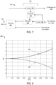
- FIG. 8 is a graph 800 depicting an example of frequency response 802 associated with a wideband remote unit 108.
- the wideband remote 108 can use a compensation digital filter to amplify high frequency content that can be attenuated by the sin( x )/ x response.
- the digital filtering can be performed by the DAC 214, by a processing device in the processing module 212, by an analog filter following the DAC 214 in the downlink path 203, or by any other suitable component.
- FIG. 8 is associated with a 214 DAC that uses a sampling rate of 7 gigasamples per second.
- FIG. 8 also depicts a compensation 804 for the loss in gain from the sin( x )/ x response that can be provided by a compensation filter.
- a DAS 102 having wideband remote units 108a-n can support Multiple-Input Multiple-Output ("MIMO") communication.
- the wideband remote units 108a-n can be deployed on a smaller grid than conventional remote units.
- a conventional remote unit may service a grid of 100 feet (or approximately 30 meters) covering 10,000 square feet (or approximately 900 square meters).
- a wideband remote unit 108 may service a grid of 30 feet (or approximately 10 meters) covering 900 square feet (or approximately 100 square meters). These numbers are provided for illustrative purposes only; other distance and coverage areas may be applicable. Reducing a grid size can reduce a required amount of transmit power in the downlink direction.
- the spacing of wideband remote units 108a-n for MIMO operation can be selected based on a required grid size required for the DAS 102.
- FIG. 9 is a diagram depicting an example of wideband remote units deployed in a configuration 900 that can be used for MIMO operation according to one aspect.
- the wideband remote units 108 can be built into or otherwise coupled to ceiling tiles 902.
- Other examples of structures into which the wideband remote units 108 can be built or to which the wideband remote units 108 can be coupled include light fixtures, power outlets, smoke or fire detectors, etc.
- the wideband remote units 108 can be used for MIMO operation.
- the wideband remote units 108 can be spaced apart from one another such that adjacent wideband remote units 108 can be used in a MIMO configuration. For example, as depicted in FIG.
- the sixteen wideband remote units 108a-n are grouped into four sets of four wideband remote units 108a-n to provide a four-by-four MIMO configuration.
- the MIMO streams can be generated at the unit 104.
- the unit 104 can synchronize the MIMO streams in time such that a set or subset of the remote units 108a-n configured for MIMO operation can transmit MIMO streams simultaneously or near-simultaneously.
- the DAS 102 can be configured to determine the proximity of a given wideband remote unit 108 to other wideband remote units 108. Triangulation or some intelligent method of determining relative spacing between wideband remote units 108 can be used to identify which wideband remote units 108 are to be used in a MIMO configuration. The power levels of the identified wideband remote units 108 can be adjusted to compensate for path loss.
- the wideband remote units 108 can adaptively change from MIMO operation to single-input/single-output ("SISO") operation in cases where low multi-path is experienced in the particular installation.
- SISO single-input/single-output
- wideband remote units 108 in a DAS 102 can facilitate public safety features. For example, using a wideband remote unit 108 that services a smaller grid (e.g., 10 square feet) can allow for more precise geolocation of a terminal device (e.g., a mobile phone) than a conventional remote unit that services a larger grid (e.g., 100 square feet) employing proximity detection as an example.
- a unit 104 that receives uplink signals can identify a given uplink signal as being received at a given wideband remote unit 108 (or group of wideband remote units 108) prior to combining the uplink signal with other uplink signals.
- a processing device in a wideband remote unit 108 may implement a measurement receiver function that is used to determine the signal strength of uplink signals received from a given terminal device.
- the wideband remote unit 108 can notify other units in the DAS 102 that the terminal device is located in close proximity to the wideband remote based on the signal strength of the uplink signal exceeding a specified threshold.
- FIG. 10 is a flow chart depicting an example of a process 1000 for using a wideband remote unit from FIG. 1 to obtain wideband uplink data for transmission to a base station according to one aspect.
- the process 1000 is described with respect to one or more of the aspects and examples described above with respect to FIGs. 1-9 . Other implementations, however, are possible.
- the process 1000 involves receiving wideband signals including uplink RF signals and leaked downlink RF signals, as depicted in block 1002.
- one or more of the wideband remote units 108a-n can receive wideband signals, as described above with respect to one or more of the examples in FIGs. 1-3 .
- a wideband remote unit 108 can receive the wideband signals via an uplink path 201 that is communicatively coupled to one or more antennas 200.
- Uplink RF signals can include signals received by the wideband remote unit 108 from terminal devices.
- uplink RF signals can have uplink signal powers at or near a noise level (e.g. the thermal noise level) associated with the wideband remote unit (e.g., noise generated by the antenna 200).
- Leaked downlink RF signals can include signal power from one or more downlink RF signals traversing a downlink path 203 of the wideband remote unit 108 and transmitted using one or more elements of the antenna 200 of the wideband remote unit 108.
- the process 1000 also involves converting the wideband RF signals to digital RF signals, as depicted in block 1004.
- one or more of the wideband remote units 108a-n can convert received wideband RF signals into digital RF signals to be provided to a unit 104, as described above with respect to one or more of the examples in FIGs. 2 and 3 .
- a wideband remote unit 108 can include an ADC 210 having a dynamic range suitable for digitizing uplink signals with low signal powers and leaked downlink signals with high signal powers, as described above with respect to FIG. 2 .
- a dynamic range of the ADC 210 can have a minimum value corresponding to the noise level and a maximum value corresponding to the downlink signal power of downlink signals transmitted by the wideband remote unit 108.
- the dynamic range of the ADC 210 can be based on or otherwise correspond to a data rate of the communication link 220, as described above with respect to FIG. 2 .
- the ADC 210 can be configured with a sampling rate that corresponds to a maximum RF frequency of the wideband signals.
- the sampling rate of the ADC 210 can be twice the frequency of a maximum RF frequency of the wideband spectrum received by the remote unit 108.
- the sampling rate of the ADC 210 can be configured based on one or more of a dynamic range of the ADCs and a data rate of the communication link 220, as described above with respect to FIG. 2 .
- the process 1000 also involves providing the digital RF signals from a remote unit to a unit in communication with a base station, as depicted in block 1006.
- one or more of the wideband remote units 108a-n can transmit the digital RF signals generated from the received wideband RF signals to the unit 104 via a communication link 220, as described above with respect to one or more of the examples in FIGs. 2 and 3 .
- the process 1000 also involves mitigating the digital RF signals corresponding to the leaked downlink RF signals in a combined uplink signal to be transmitted to the base station, as depicted in block 1008.
- the unit 104 can use the non-duplexer isolation sub-system 404 to filter, exclude, cancel, attenuate, or otherwise mitigate spurious signals from a combined uplink signal, as described above with respect to one or more of the examples in FIGs. 4-7 .
- one or more devices of the unit 104 can filter a digital RF signal (e.g., a digital signal corresponding to a leaked downlink signal) from a combined uplink signal generated using one or more uplink signals (e.g., another digital RF signal corresponding to an uplink RF signal received by the remote unit 108.
- a digital RF signal e.g., a digital signal corresponding to a leaked downlink signal
- a combined uplink signal generated using one or more uplink signals (e.g., another digital RF signal corresponding to an uplink RF signal received by the remote unit 108.
- one or more devices of the unit 104 can cancel or otherwise mitigate a digital RF signal (e.g., a digital signal corresponding to a leaked downlink signal) from a combined uplink signal generated using one or more uplink signals (e.g., another digital RF signal corresponding to an uplink RF signal received by the remote unit 108.
- a digital RF signal e.g., a digital signal corresponding to a leaked downlink signal
- a combined uplink signal generated using one or more uplink signals (e.g., another digital RF signal corresponding to an uplink RF signal received by the remote unit 108.
- one or more devices of the unit 104 can mute or otherwise attenuate a digital RF signal (e.g., a digital signal corresponding to a leaked downlink signal) from a combined uplink signal generated using one or more uplink signals (e.g., another digital RF signal corresponding to an uplink RF signal received by the remote unit 108.
- a digital RF signal e.g., a digital signal corresponding to a leaked downlink signal
- a combined uplink signal generated using one or more uplink signals (e.g., another digital RF signal corresponding to an uplink RF signal received by the remote unit 108.
- the wideband remote unit can include one or more antennas and an analog-to-digital converter ("ADC").
- the antenna can receive wideband signals.
- the wideband signals can include an uplink RF signal and a leaked downlink RF signal.
- the uplink RF signal can have an uplink signal power at or near a noise level.
- the leaked downlink RF signal can have a downlink signal power greater than the uplink signal power.
- the ADC can convert the received wideband signals to digital RF signals representing the uplink signal and the downlink signal.
- the wideband remote unit can transmit the digital RF signals to a unit of a DAS that is in communication with a base station.
Description
- The present disclosure relates generally to telecommunication systems and more particularly (although not necessarily exclusively) to wideband remote units for distributed antenna systems.
- A distributed antenna system ("DAS") can be used to provide wireless communications coverage in a variety of environments, particularly in large structures such as office buildings, convention halls, airports, stadiums, and the like. A DAS can include one or more head-end units (e.g., master units) that are communicatively coupled to one or more base stations. A DAS can also include multiple remote units that are communicatively coupled to each head-end unit. The remote units, each of which can include one or more transceivers and antennas, can be distributed across a coverage area. The remote units can transmit the downlink signals to mobile phones or other terminal devices within coverage areas serviced by the remote units.
- Remote units for a DAS may use large amounts of electrical power and may have a large physical size. For example, the power requirements and size of a remote unit may be increased if the remote unit includes extensive analog circuitry for downconverting or otherwise modifying received analog signals prior to generating a digitized representation of communication channels of interest.
- The power requirements and size of a conventional remote unit may also be increased by using multiple RF transceivers in a DAS to transmit and receive signals in multiple frequency bands. For example a remote unit may include a first RF transceiver with associated analog circuitry for communicating signals in an Advanced Mobile Phone System ("AMPS") band, a second RF transceiver with associated analog circuitry for communicating signals in a Personal Communications Service ("PCS") band, and a third RF transceiver with associated analog circuitry for communicating signals in an Advanced Wireless Services ("AWS") band, etc. One or more of the power requirements and physical size of a remote unit may increase costs associated with manufacturing or installing the remote unit.
- For example, a distributed antenna system comprising a host unit and at least one remote antenna unit that is communicatively coupled to the host unit is disclosed in US Patent Application
US 2012/3229523A1 . Further, for example, a distributed antenna system having a downlink communication path, an uplink communication path, and a non-duplexer isolator sub-system is disclosed in US Patent ApplicationUS 2012/0309328A1 . - The invention is defined by the independent claims. Features of embodiments are defined by the dependent claims. The present disclosure describes devices, systems, and methods involving a wideband remote unit for a distributed antenna system ("DAS").
- In some aspects, a method is provided. The method can involve a wideband remote unit receiving, via an uplink path, wideband signals that include an uplink RF signal and a leaked downlink RF signal. The uplink RF signal can have an uplink signal power at or near a noise level of the wideband remote unit. The leaked downlink RF signal can have a downlink signal power greater than the uplink signal power. The leaked downlink RF signal can be a downlink RF signal that is transmitted by the remote unit and received by an antenna of the remote unit. The method can also involve converting, by the wideband remote unit, the received wideband signals to digital RF signals that represent the uplink signal and the downlink signal. The method can also involve transmitting, by the wideband remote unit, the digital RF signals to a unit of the DAS for transmission to a base station by the unit.
- In other aspects, a wideband remote unit is provided. The wideband remote unit can include one or more antennas and an analog-to-digital converter ("ADC"). An antenna of the wideband remote unit can receive wideband signals. The wideband signals can include an uplink RF signal and a leaked downlink RF signal. The uplink RF signal can have an uplink signal power at or near a noise level of the wideband remote unit. The leaked downlink RF signal can have a downlink signal power greater than the uplink signal power. The ADC can convert the received wideband signals to digital RF signals representing both the uplink signal and the downlink signal. The wideband remote unit can transmit the digital RF signals to a unit of a DAS for transmission to a base station.
- In other aspects, a DAS is provided that includes one or more wideband remote units and a unit that can communicate with a base station. The wideband remote unit can receive wideband signals. The wideband signals can include an uplink RF signal and a leaked downlink RF signal. The uplink RF signal can have an uplink signal power at or near a noise level of the wideband remote unit. The leaked downlink RF signal can have a downlink signal power greater than the uplink signal power. The wideband remote unit can convert the received wideband signals to digital RF signals representing the uplink signal and the downlink signal. The unit can receive the digital RF signals from the remote unit. The unit can transmit an uplink signal corresponding to one of the digital RF signals to a base station. The unit can mitigate another digital RF signal corresponding to the leaked downlink RF signal.
- In particular, the instant application shall concern the subject matter as described and claimed in the parent application of the instant application, corresponding to international application
WO 2015/160777 A1 . - In particular, according to a first subject matter, a method comprises: receiving, via an uplink path of a wideband remote unit of a distributed antenna system, wideband signals comprising an uplink RF signal and a leaked downlink RF signal, the uplink RF signal having an uplink signal power and the leaked downlink RF signal having a downlink signal power greater than the uplink signal power, wherein the leaked downlink RF signal is from a downlink RF signal transmitted by the wideband remote unit; converting, by the wideband remote unit, the received wideband signals to a first digital RF signal that represents the uplink signal and to a second digital RF signal that represents the downlink signal; and transmitting, by the wideband remote unit, the first digital RF signal and the second digital RF signal to a unit of the distributed antenna system in communication with a base station.
- According to one aspect of the first subject matter, the method further comprises providing, via a downlink path of the wideband remote unit, the downlink RF signal to an antenna that transmits the downlink RF signal, wherein the downlink path is coupled via a splitter-combiner to the uplink path the antenna.
- According to one aspect of the first subject matter, the method further comprises: transmitting, by the unit, an uplink signal to the base station, wherein the uplink signal corresponds to the first digital RF signal; and mitigating, by the unit, the second digital RF signal corresponding to the leaked downlink RF signal.
- According to one aspect of the first subject matter, mitigating the second digital RF signal comprises at least one of: filtering the second digital RF signal from a combined uplink signal generated from the first digital RF signal; cancelling the second digital RF signal from the combined uplink signal; or attenuating the second digital RF signal.
- According to one aspect of the first subject matter, mitigating the second digital RF signal comprises: correlating a downlink signal traversing the downlink path with a signal component traversing the uplink path; generating a cancellation signal corresponding to the second digital RF signal based on correlating the downlink signal traversing the downlink path with the signal component traversing the uplink path; and combining the cancellation signal with a combined uplink signal generated from the first digital RF signal.
- According to one aspect of the first subject matter, the uplink signal power is at a thermal noise level associated with the wideband remote unit, wherein the method further comprises configuring an analog-to-digital converter of the wideband remote unit with a dynamic range having a minimum value corresponding to the thermal noise level and a maximum value corresponding to the downlink signal power.
- According to one aspect of the first subject matter, the method further comprises configuring the dynamic range based on a data rate for a digital communication link between the wideband remote unit and the unit.
- According to one aspect of the first subject matter, the downlink RF signal comprises a first multiple-input, multiple-output data stream received from the unit, wherein the method further comprises: transmitting, by an additional wideband remote unit of the distributed antenna system, an additional downlink RF signal comprising a second multiple-input, multiple-output data stream; receiving, by the additional wideband remote unit, an additional leaked downlink RF signal, wherein the additional leaked downlink RF signal is obtained from the additional downlink RF signal transmitted by the additional wideband remote unit; transmitting, by the additional wideband remote unit, a third digital RF signal to the unit, wherein the third digital RF signal is generated from the additional leaked downlink RF signal; and mitigating, by the unit, the second digital RF signal and the third digital RF signal.
- According to another, second subject matter, a wideband remote unit comprises: an antenna configured for receiving wideband signals comprising an uplink RF signal and a leaked downlink RF signal, the uplink RF signal having an uplink signal power and the leaked downlink RF signal having a downlink signal power greater than the uplink signal power, wherein the leaked downlink RF signal is from a downlink RF signal transmitted by the wideband remote unit; and an analog-to-digital converter configured for converting the received wideband signals to a first digital RF signal that represents the uplink signal and to a second digital RF signal that represents the downlink signal, wherein the wideband remote unit is configured for transmitting the first and second digital RF signals to a unit of a distributed antenna system that is communicatively coupled to a base station.
- According to one aspect of the second subject matter, the wideband remote unit further comprises a downlink path configured for providing the downlink RF signal to the antenna and an uplink path comprising the analog-to-digital converter, wherein the uplink path is communicatively coupled to the downlink path via a splitter-combiner of the wideband remote unit.
- According to one aspect of the second subject matter, the analog-to-digital converter of the wideband remote unit has a dynamic range having a minimum value corresponding to a thermal noise level associated with the wideband remote unit and a maximum value corresponding to the downlink signal power.
- According to one aspect of the second subject matter, the dynamic range is based on a data rate for a digital communication link between the wideband remote unit and the unit.
- According to one aspect of the second subject matter, the analog-to-digital converter of the wideband remote unit has a sampling rate corresponding to a maximum RF frequency of the wideband signals and the data rate for the digital communication link.
- According to a further, third subject matter, a distributed antenna system comprises: a wideband remote unit configured for: receiving wideband signals comprising an uplink RF signal and a leaked downlink RF signal, the uplink RF signal having an uplink signal power and the leaked downlink RF signal having a downlink signal power greater than the uplink signal power, wherein the leaked downlink RF signal is from a downlink RF signal transmitted by the wideband remote unit, converting the received wideband signals to a first digital RF signal that represents the uplink signal and a second digital RF signal that represents the downlink signal, and transmitting the first and second digital RF signals to a unit; and the unit configured for: transmitting an uplink signal to a base station, wherein the uplink signal corresponds to the first digital RF signal; and mitigating the second digital RF signal corresponding to the leaked downlink RF signal.
- According to one aspect of the third subject matter, the wideband remote unit comprises a downlink path configured for providing the downlink RF signal to an antenna of the wideband remote unit, wherein the downlink path is coupled via a splitter-combiner to the antenna and an uplink path configured for receiving the wideband signals.
- According to one aspect of the third subject matter, the unit comprises a non-duplexer isolation sub-system configured for mitigating the second digital RF signal.
- According to one aspect of the third subject matter, the wideband remote unit comprises an analog-to-digital converter with a dynamic range having a minimum value corresponding to a thermal noise level associated with the wideband remote unit and a maximum value corresponding to the downlink signal power.
- According to one aspect of the third subject matter, the dynamic range is based on a data rate for a digital communication link between the wideband remote unit and the unit.
- According to one aspect of the third subject matter, the analog-to-digital converter of the wideband remote unit has a sampling rate corresponding to a maximum RF frequency of the wideband signals and the data rate for the digital communication link.
- According to one aspect of the third subject matter, the downlink RF signal comprises a first multiple-input, multiple-output data stream received from the unit, wherein the distributed antenna system further comprises: an additional wideband remote unit configured for: transmitting an additional downlink RF signal comprising a second multiple-input, multiple-output data stream, receiving an additional leaked downlink RF signal, wherein the additional leaked downlink RF signal is obtained from the additional downlink RF signal transmitted by the additional wideband remote unit, and transmitting a third digital RF signal to the unit, wherein the third digital RF signal is generated from the additional leaked downlink RF signal, wherein the unit is further configured for mitigating the third digital RF signal.
- These illustrative aspects and features are mentioned not to limit or define the disclosure, but to provide examples to aid understanding of the concepts disclosed in this application. Other aspects, advantages, and features of the present disclosure will become apparent after review of the entire application.
-
-
FIG. 1 is a block diagram depicting an example of a distributed antenna system ("DAS") that includes wideband remote units according to one aspect of the present disclosure. -
FIG. 2 is a block diagram depicting an example of a wideband remote unit of the DAS fromFIG. 1 according to one aspect of the present disclosure. -
FIG. 3 is a block diagram depicting an example of a processing module of a remote unit fromFIG. 2 according to one aspect of the present disclosure. -
FIG. 4 is a block diagram depicting an example of a unit of the DAS fromFIG. 1 according to one aspect of the present disclosure. -
FIG. 5 is a block diagram depicting an example of a non-duplexer isolation sub-system of the unit fromFIG. 4 that includes a configurable filter according to one aspect of the present disclosure. -
FIG. 6 is a block diagram depicting another example of a non-duplexer isolation sub-system of the unit fromFIG. 4 that includes a cancellation sub-system according to one aspect of the present disclosure. -
FIG. 7 is a block diagram depicting another example of a non-duplexer isolation sub-system of the unit fromFIG. 4 that includes an attenuation sub-system according to one aspect of the present disclosure. -
FIG. 8 is a graph depicting an example of frequency response associated with a wideband remote unit fromFIGs. 1 and 2 according to one aspect of the present disclosure. -
FIG. 9 is a diagram depicting an example of wideband remote units deployed in a configuration that can be used for multiple-input/multiple-output operation according to one aspect of the present disclosure. -
FIG. 10 is a flow chart depicting an example of a process for using a wideband remote unit fromFIGs. 1 and 2 to obtain wideband uplink data according to one aspect of the present disclosure. - The present disclosure relates to a wideband remote unit for a distributed antenna system ("DAS"). A wideband remote unit can include any remote unit for a DAS that is configured to generate digitized RF uplink signals from analog uplink RF signals that are received at frequencies over a wideband spectrum (e.g., 200 MHz to 3 GHz). A wideband spectrum can include a spectrum including frequency bands associated with multiple types of telecommunication providers (e.g., code division multiple access ("CDMA") systems, Long Term Evolution ("LTE") systems, etc.). The wideband remote unit can transmit the digitized RF uplink signals to a head-end unit or other suitable unit of the DAS.
- In some aspects, the wideband remote unit can perform some analog and signal processing. The wideband remote unit can be limited to transmitting signals of interest, receiving signals of interest, and transporting the signals to a central unit in a DAS for processing (e.g., a head-end unit, an expansion unit, etc.). The wideband remote unit can be implemented in a manner that allows the wideband remote unit to have one or more of a smaller size or lower power requirements as compared to other remote units.
- In some aspects, the wideband remote unit can be implemented without frequency translation circuitry. For example, the wideband remote unit can include a high-speed analog-to-digital converter ("ADC") that can sample signals at a sufficiently high sampling rate that allows the wideband remote unit to omit down-conversion circuitry for converting RF signals to intermediate frequency ("IF") signals.
- In additional or alternative aspects, the wideband remote unit can be implemented without isolation circuitry for isolating uplink signals from downlink signals. For example, an ADC of the wideband remote unit can have a sufficiently wide dynamic range to digitally represent low-power uplink signals in the uplink path and high-power downlink signals that leak to the uplink path. Digitally representing signals over a wide dynamic range can allow a head-end unit or other suitable high-power unit in the DAS to attenuate leaked downlink signals in the uplink path. Using a head-end unit or other suitable high-power unit in the DAS rather than the remote unit to attenuate leaked downlink signals in the uplink path can limit the amount of circuitry required by the remote unit.
- In some aspects, the wideband remote unit can be used without specifically designing or otherwise configuring the wideband remote unit for operation with a given telecommunication standard, frequency band, or other telecommunication technology. For example, the wideband remote unit can include a wideband receiver that can be used to receive signals in multiple frequency bands.
- Detailed descriptions of certain examples are discussed below. These illustrative examples are given to introduce the reader to the general subject matter discussed here and are not intended to limit the scope of the invention as defined by the claims. The following sections describe various additional aspects and examples with reference to the drawings in which like numerals indicate like elements, and directional descriptions are used to describe the illustrative examples but, like the illustrative examples, should not be used to limit the present disclosure. The various figures described below depict examples of implementations for the present disclosure, but should not be used to limit the present disclosure.
-
FIG. 1 is a block diagram depicting an example of aDAS 102 that includes widebandremote units 108a-n according to one aspect. TheDAS 102 can communicate signals between one ormore base stations 101 or other transceiver devices (e.g., repeaters) and terminal devices in one or more coverage zones serviced by theDAS 102. Terminal devices can be electronic devices used to communicate one or more of voice and data via a telecommunication system, such as (but not limited to) mobile phones. - The
DAS 102 can include one ormore units 104. Examples of aunit 104 include a head-end unit, a base station router, or other suitable unit that can communicate with a base station. In some aspects, theunit 104 can be a head-end unit or other suitable unit that can communicate with one ormore base stations 101 or other transceiver devices in communication with theDAS 102. A head-end unit can include, for example, an optical transceiver that transmits optical signals to the widebandremote units 108a-n. The head-end unit or othersuitable unit 104 can communicate withremote units 108a-n in different coverage zones of thesame DAS 102. In additional or alternative aspects, theunit 104 can be included in a base station router or other suitable device that can communicate signals between one ormore base stations 101 and one or more head-end units. In additional or alternative aspects, theunit 104 can be included in an extension unit or other suitable unit that can communicate signals between one or more head-end units and the widebandremote units 108a-n. - The
DAS 102 can also includeremote units 108a-n having respectivewideband RF transceivers 110a-n. Each of the widebandremote units 108a-n can include transceiver devices that can include or be communicatively coupled to one or more antennas. One example of a remote unit is a universal access point. ADAS 102 can include any number ofunits 104 and any number ofremote units 108a-n. - The
DAS 102 can communicate signals to and from terminal devices via theunit 104 and the widebandremote units 108a-n that service one or more coverage zones. Theunit 104 can be communicatively coupled with thebase station 101 and the widebandremote units 108a-n in any suitable manner. Communicatively coupling devices in aDAS 102 or other telecommunication system can involve establishing, maintaining, or otherwise using a communication link (e.g., a cable, an optical fiber, a wireless link, etc.) to communicate information between the devices. Any suitable types of communication links can be used in theDAS 102. A suitable communication link can be a wired connection or a wireless connection. Types of wired connections can include, for example, a connection via a copper cable, an optical fiber, or another suitable communication medium. Types of wireless connections can include, for example, a wireless RF communication link or a microwave link. The type of communication link between thebase station 101 and theunit 104 can be the same as or different from the type of communication link between theunit 104 and the widebandremote units 108a-n. - The
unit 104 can provide downlink signals from thebase station 101 to the widebandremote units 108a-n and receive uplink signals from the widebandremote units 108a-n to be provided to thebase station 101. Downlink signals can include signals provided from thebase station 101 and transmitted by the widebandremote units 108a-n in coverage zones. Uplink signals can include signals transmitted by terminal devices and received by the widebandremote units 108a-n. - The wideband
remote units 108a-n can provide signal coverage in one or more coverage zones. Providing signal coverage in the coverage zones can include wirelessly transmitting downlink signals received from theunit 104 to terminal devices in the coverage zones. Providing signal coverage in the coverage zones can also include wirelessly receiving uplink signals from the mobile communication devices or other terminal devices in the coverage zones. The widebandremote units 108a-n can transmit the uplink signals to theunit 104. Theunit 104 can transmit the uplink signals to thebase station 101. - Although
FIG. 1 depicts direct links between theunit 104 and the widebandremote units 108a-n, other implementations are possible. In some aspects, theunit 104 can be communicatively coupled to the widebandremote units 108a-n via one or more extension units or other intermediate devices. - The
unit 104 can combine uplink transmissions received from some or all of the widebandremote units 108a-n into a combined uplink signal, such as a composite signal. A transmitter of theunit 104 can transmit the combined uplink signal to an uplink receiver of thebase station 101. Theunit 104 can use theprocessing module 106 to combine uplink transmissions received from the wideband remote units 108an. Theprocessing module 106 can include one or more devices configured to select uplink signals for a combination, programming instructions executable by a processor to select uplink signals for a combination, or any suitable combination thereof. - In some aspects, the wideband
remote units 108a-n can operate using a reduced amount of RF circuitry as compared to conventional remote units. Reducing the amount of circuitry in a remote unit can reduce one or more of the size of the remote unit and the costs associated with manufacturing or installing the remote unit. The amount of circuitry used in a remote unit can be reduced by, for example, using a single RF transceiver that is configured for digitizing signals having frequencies within large frequency bandwidths for digital transport to aunit 104 or other head-end unit. The amount of circuitry used in a widebandremote unit 108 can also be reduced by, for example, omitting RF signal processing components such as up-conversion components, down-conversion components, isolation devices, etc. -
FIG. 2 is a block diagram depicting an example of a widebandremote unit 108 according to one aspect. The widebandremote unit 108 can include anantenna 200, a multiplewideband RF transceivers 110, and aprocessing module 212. - The multiple
wideband RF transceivers 110 can include anuplink path 201 and adownlink path 203. Theuplink path 201 can include a low-noise amplifier 204, ananti-aliasing filter 206, avariable gain device 208, and anADC 210. In some aspects, theuplink path 201 can be limited to the devices depicted inFIG. 2 . In other aspects, theuplink path 201 can include additional devices other than those depicted inFIG. 2 . Thedownlink path 203 can include a digital-to-analog converter ("DAC") 214, animage filter 216, and apower amplifier 218. In some aspects, thedownlink path 203 can be limited to the devices depicted inFIG. 2 . In other aspects, thedownlink path 203 can include additional devices other than those depicted inFIG. 2 . - In the uplink direction, one or more elements of the
antenna 200 can receive uplink signals. Although asingle antenna 200 is depicted for illustrative purposes, other implementations are possible. In some aspects, one or more antenna elements can be used for transmitting signals and one or more other antenna elements can be used for receiving signals. In other aspects, one or more antenna elements can be used for transmitting signals and receiving signals in a time-division multiplexed manner. - A splitter-
combiner 202 in the multiplewideband RF transceivers 110 can communicatively couple thedownlink path 203 and theuplink path 201 to a common port that is communicatively coupled to theantenna 200. The splitter-combiner 202 can split downlink signals to be transmitted via theantenna 200 from uplink signals that are received via theantenna 200. The low-noise amplifier 204 can amplify the uplink signals to improve the signal-to-noise ratio of the received uplink signals. - The
anti-aliasing filter 206 can filter the received uplink signals to reduce or prevent aliasing. Aliasing can be caused by converting analog uplink signals to digital uplink signals using theADC 210. For example, the low-noise amplifier 204 can have a high dynamic range. The high dynamic range can compensate for limited attenuation from thedownlink path 203. Theanti-aliasing filter 206 in theuplink path 201 can reduce or prevent undesired signals from aliasing into desired Nyquist zones. One example of ananti-aliasing filter 206 is a surface acoustic wave ("SAW') filter. In some aspects, a mixer or other demodulation device can be included in theuplink path 201. An example of a bandwidth that may be used by theanti-aliasing filter 206 is 75 MHz. For sample rates as high as 7 GHz, theanti-aliasing filter 206 can be a low-pass filter with a cut-off frequency below 3.5 GHz, which is the limit of the Nyquist zone. In another example, theanti-aliasing filter 206 can use a 3.2 GHz sample rate and can have an RF input bandwidth between 30 MHz and 450 MHz. - In another example, the
anti-aliasing filter 206 can use a sample rate of up to 3 GHz and can have a 2.5 GHz input bandwidth. In this example, the frequency range from 700 MHz to 1 GHz can be sampled in the first Nyquist zone, and the frequency range from 1.7 GHz to 2.2 GHz can be sampled in the second Nyquist zone. The sample rate for theanti-aliasing filter 206 can be selected (e.g., 2.3 GHz) to avoid aliasing of the two frequency ranges onto the same frequency. - The
ADC 210 can convert the analog uplink signal to a digital uplink signal. TheADC 210 can digitize uplink signals in a manner that allows for the omission of frequency translation circuitry (e.g., down-conversion circuitry such as a mixer and local oscillator) from theuplink path 201. In some aspects, theADC 210 can use a sampling rate suitable for sampling signals from a wideband spectrum. TheADC 210 may be configured to sample analog uplink RF signals at a sufficiently high sampling rate such that high-frequency signals in a wideband spectrum are sampled at a rate greater than or equal to a Nyquist rate (e.g., twice the frequency of the sampled analog signal). For example, a wideband spectrum may include signals having frequencies up to 3.5 GHz, and theADC 210 may use a sampling rate of 7 GHz or higher. - A wideband spectrum can include a spectrum having frequency bands associated with multiple types of telecommunication providers. In some aspects, the wideband behavior of the
remote unit 108 can involve theremote unit 108 being nonselective such that all RF bands within the frequency range of theremote unit 108 are processed. For example, theremote unit 108 can be implemented without using dedicated filters to isolate one or more bands. The wideband behavior of theremote unit 108 can also involve theremote unit 108 processing both downlink and uplink frequencies rather than using one or more filters to select a downlink frequency band or uplink frequency band for processing. - Additionally or alternatively, the
ADC 210 can digitize uplink signals in a manner that allows for implementing theremote unit 108 without analog circuitry for isolating uplink signals from downlink signals. In some aspects, theADC 210 can have a resolution that is suitable for digitizing signals within a wideband spectrum that have a wide range of signal powers. For example, the widebandremote unit 108 may be implemented without a duplexer or other analog devices that isolate downlink signals transmitted to terminal devices by one or more elements of theantenna 200 from uplink signals received from terminal devices by one or more elements of theantenna 200. The absence of a duplexer or other analog isolation devices can allow the downlink signals transmitted by one or more elements of theantenna 200 to be received by one or more elements of theantenna 200 and provided to theuplink path 201 of the widebandremote unit 108. These downlink signals received by theantenna 200 may have a higher signal strength than uplink signals received from terminal devices. Using anADC 210 with a sufficient resolution can allow one or more digital processing devices in one or more of the widebandremote unit 108 and theunit 104 to distinguish between low-power uplink signals and high-power uplink signals that both traverse theuplink path 201. - The resolution of the
ADC 210 can be expressed in a number of bits that correspond to a number of available signal power levels that can be digitally represented. For example, an n-bit ADC 210 can be used to digitally represent 2 n signal power levels. The dynamic range of the ADC 210 (e.g., the range of signal power levels that can be digitally represented using the ADC 210) can correspond to number n of bits for theADC 210 and the increment between the digitally represented power levels. For example, for an increment of m dB per bit, the dynamic range of an n-bit ADC 210 is n × m dB. A sufficiently wide dynamic range of theADC 210 can allow theanti-aliasing filter 206 to digitize both uplink signals having low signal powers and downlink signals that may leak into theuplink path 201. One example of theADC 210 is a delta-sigma ADC. - In some aspects, the dynamic range for the ADC can be 6.02 dB × n + 1.76 dB. In other aspects involving higher bit numbers, the signal dynamic range improvement may decrease ( e.g., to a factor of 3 dB increasing from n=12 to n=14).
- The sampling rate of the
ADC 210, the number of bits used by theADC 210 to express signal power levels, and a data rate of acommunication link 220 from the widebandremote unit 108 to theunit 104 can be related. The product of the sampling rate of theADC 210 and the number of bits used by theADC 210 can be less than or equal to a data rate of aserial communication link 220 used to communicate digital uplink signals to theunit 104. For example, theADC 210 may sample values from an analog uplink signal at a rate of r samples per second. The ADC can encode each sampled value using n bits. Communicating n-bit samples at a rate of r samples per second can involve using acommunication link 220 having a data rate of r × n bits per second. - The following non-limiting example illustrates (without limitation) a sample configuration for the wideband
remote unit 108. With respect to the sampling frequency of the widebandremote unit 108, the widebandremote unit 108 may be used to receive uplink signals in frequency bands from 200 MHz to 3 GHz. Theanti-aliasing filter 206 can have a low pass corner frequency of 3 GHz with a stop-band frequency of 4 GHz. TheADC 210 can be configured to digitally represent the bandwidth of 3.5 GHz that accounts for the uplink frequency bands and the stop-band frequency by using a sampling rate of at least 7 GHz (e.g., double the highest frequency of 3.5 GHz). With respect to the dynamic range of the widebandremote unit 108, the signal powers of uplink signals received by the widebandremote unit 108 may be as low as -105 dBm. The signal powers of downlink signals transmitted by the widebandremote unit 108 may be as high as +12 dBm. If thedownlink path 203 and theuplink path 201 are not isolated from one another, the range of signal powers for signals traversing the uplink path 201 (e.g., low-power uplink signals, downlink signals received by one or more elements of the antenna 200) can be from -105 dBm to +12 dBm, for a total range of 117 dB. If an increment of 6 dB is used to represent different signal power levels, theADC 210 can use 20 bits (117 dB divided by 6 dB per bit) to digitally represent sampled signal power values of analog uplink RF signals. In some cases, the data rate for aserial communication link 220 between the widebandremote unit 108 and theunit 104 can be at least 140 Gbps (the product of the 7-GHz sampling rate and the 20-bit digital value) in the uplink direction. In other cases, the data rate for theserial communication link 220 can be reduced further using filtering and sample rate conversion. - In the downlink direction, the wideband
remote unit 108 can receive digital downlink signals from theunit 104. For example, a digital signal representing a downlink frequency band can be provided to aDAC 214 of the widebandremote unit 108 via a serial communication link from aunit 104. - The digital downlink signals can be converted to analog RF downlink signals by the high-
speed DAC 214. TheDAC 214 can generate RF signals without performing frequency translation in the analog domain using frequency translation circuitry (e.g. up-conversion circuitry such as a mixer and local oscillator in the downlink path 203). In some aspects, frequency translation may be performed in the digital domain using high-speed digital circuitry in theDAC 214. In additional or alternative aspects, frequency translation may be performed in the digital domain using aprocessing module 212. - The
image filter 216 can filter the RF downlink signals to remove images generated by theDAC 214. TheDAC 214 may create images as a result of the sample-and-hold operation performed by theDAC 214. Theimage filter 216 that removes or reduces these images can be an image rejection analog filter in thedownlink path 203. - The RF downlink signals can be amplified by the
power amplifier 218 for transmission to one or more terminal devices. - In some aspects, the wideband
remote unit 108 can include a singlewideband RF transceiver 110 that is configured to receive and transmit signals at frequencies within all frequency bands of interest for aDAS 102. In other aspects, a widebandremote unit 108 can include multiplewideband RF transceivers 110. Each of thewideband RF transceivers 110 can receive and transmit signals at frequencies within a portion of the frequency bands of interest for aDAS 102. For example, a first wideband RF transceiver in the widebandremote unit 108 can transmit or receive signals having frequencies in a frequency band of 200 MHz to 1 GHz, a second wideband RF transceiver in the widebandremote unit 108 can transmit or receive signals having frequencies in a frequency band of 1 GHz to 2 GHz, and a third wideband RF transceiver in the widebandremote unit 108 can transmit or receive signals having frequencies in a frequency band of 2 GHz to 3 GHz. - The wideband
remote unit 108 can include simplified circuitry as compared to an RF transceiver of a conventional remote unit. In some aspects, the widebandremote unit 108 can omit circuitry used for frequency translation that would otherwise be performed in one or both of theuplink path 201 and the downlink path 203 (e.g., up-conversion components, down-conversion components, amplifiers used to compensate for loss introduced by frequency translation, etc.). For example, conventional remote units of a DAS may include a large amount of RF, analog, and digital circuitry, such as adownlink path 203 and anuplink path 201 having multiple RF processing components. Thedownlink path 203 can include up-conversion circuitry (e.g., a local oscillator and a mixer) to up-convert downlink signals from IF to RF and a filter and amplifier following the up-conversion circuitry. Theuplink path 201 can include a bandpass filter, down-conversion circuitry (e.g., a local oscillator and a mixer) to down-convert uplink signals from RF to IF, and one or more amplifiers following the down-conversion circuitry. - The RF, analog, and digital circuitry of a conventional remote unit may use a large amount of power. For example, the mixers in the uplink and
downlink paths 203 can respectively attenuate uplink and downlink signals. The amplifiers following the mixers in the uplink anddownlink paths 203 can compensate for the loss introduced by the mixers. Other RF signal processing components, such as anti-aliasing filters, can be used to compensate for non-linear distortion of uplink and downlink signals introduced by the up-conversion and down-conversion circuitry. The use of the amplifiers and filters associated with up-conversion components and down-conversion components can increase one or more of the power used by a remote unit, the size of the remote unit, the costs associated with manufacturing or installing the remote unit, etc. The inclusion of the RF, analog, and digital circuitry may also increase the physical dimensions of the remote unit, thereby increasing the amount of space required to install the remote unit in a deployment environment (e.g., a building serviced using the DAS 102). - In some aspects, the wideband
remote unit 108 can be implemented without a duplexer. For example, a conventional RF transceiver may include one or more duplexers for isolating a transmitter output (e.g., downlink signals) from a receiver input (e.g., uplink signals). The duplexer can allow frequencies within the downlink frequency band to be provided from the transmitter output to the antenna and can allow frequencies within the uplink frequency band to be provided from the antenna output to the receiver. Isolating a transmitter output from a receiver input can prevent downlink signals from interfering with uplink signals. The duplexer may introduce some amount of insertion loss, which can cause some of the power amplification from the power amplifier to be wasted. The waste of power amplification can reduce the efficiency of conventional remote units. -
FIG. 3 is a block diagram depicting an example of theprocessing module 212 of the widebandremote unit 108 according to one aspect. Theprocessing module 212 can include one or more suitable processing devices that can be used to implement a digital processing section. Theprocessing module 212 can perform one or more operations on downlink signals received from aunit 104. Theprocessing module 212 can also perform one or more operations on uplink signals to be provided to theunit 104. Examples of a processing device include an application-specific integrated circuit ("ASIC"), a field-programmable gate array ("FPGA"), or another suitable processing device or suitable processing circuitry. - The
processing module 212 can include a parallel-serial converter 302, a framer-deframer 304, and adigital pre-distortion module 306. In some aspects, one or more of the parallel-serial converter 302, the framer-deframer 304, and thedigital pre-distortion module 306 can include one or more hardware devices included in or communicatively coupled to a processing device of theprocessing module 212. In additional or alternative aspects, one or more of the parallel-serial converter 302, the framer-deframer 304, and thedigital pre-distortion module 306 can include program code stored in a memory device and executed by a processing device of theprocessing module 212. In additional or alternative aspects, one or more of the parallel-serial converter 302, the framer-deframer 304, and thedigital pre-distortion module 306 can be implemented using a combination of one or more hardware devices included in or communicatively coupled to a processing device of theprocessing module 212 and program code stored in a memory device and executed by a processing device of theprocessing module 212. - In a downlink direction, the parallel-
serial converter 302 can perform one or more operations to de-serialize a serial downlink data stream into multiple digital downlink signals to be provided todifferent downlink paths 203 of the widebandremote unit 108. For example, the parallel-serial converter 302 can de-multiplex digital downlink signals from a common serial downlink data stream. In an uplink direction, the parallel-serial converter 302 can perform one or more operations to serialize parallel uplink signals into a common serialized uplink data stream to be provided to theunit 104. For example, the parallel-serial converter 302 can combine parallel uplink digital signals received from multiple uplink signal paths of the remote 108 into a serialized uplink signals. - In additional or alternative aspects, the transport between the
unit 104 and one or more of theADC 210 and theDAC 214 can use an internal format for theADC 210 and theDAC 214, which can be transported either as-is or with framing by the framer-deframer 304. In these aspects, the parallel-serial converter 302 can be omitted. - In additional or alternative aspects, a regenerating serial data link repeater can be included to restore the bits to meet the timing that is used by the
DAC 214 or theunit 104. In a downlink direction, the framer-deframer 304 can de-frame digital downlink signals to obtain downlink payload data for transmission via theantenna 200. In an uplink direction, the framer-deframer 304 can frame digital uplink signals for transmission to theunit 104. - In some aspects, the
digital pre-distortion module 306 can pre-distort downlink signals prior to digital-to-analog conversion and transmission via theantenna 200. Pre-distorting downlink signals prior to transmission via theantenna 200 can reduce or prevent downlink intermodulation products from being generated in thedownlink path 203. For example, one or more components of thedownlink path 203 or elsewhere in theremote unit 108 can include non-linearities that generate intermodulation products. Thedigital pre-distortion module 306 can pre-distort downlink signals in a manner that offsets or otherwise compensates for these non-linearities. Offsetting or otherwise compensating for these non-linearities can prevent intermodulation products from being transmitted by theremote unit 108 or reduce the intermodulation products received in theuplink path 201. In additional or alternative aspects, thedigital pre-distortion module 306 can pre-distort digital uplink signals prior to transmission to theunit 104. Pre-distorting uplink signals prior to transmission via theantenna 200 can reduce or prevent uplink intermodulation products from being generated in an uplink path to theunit 104. In some aspects, this predistortion can address the intermodulation products generated from one or more of intra-band signal combinations and interband combinations. - In other aspects, the wideband
remote unit 108 may be implemented with highly linear stages, such that thedigital pre-distortion module 306 may be omitted. - The
processing module 212 can be used to prepare digital signals for transport via theDAS 102. In theuplink path 201, theprocessing module 212 can extract frequency channels of interest and can suppress or remove unwanted signals in theuplink path 201. In thedownlink path 203, the digital processing circuit can shift frequency channels or bands of interest to a desired digital frequency prior to downlink signals being provided to theDAC 214. - In some aspects, the
processing module 212 depicted inFIG. 3 can be omitted from the widebandremote unit 108 and theunit 104 can include a processing module for performing the digital signal processing described above. For example,FIG. 4 is a block diagram depicting an example of aunit 104. Theunit 104 can include a downlinksignal processing section 402, anon-duplexer isolation sub-system 404, and an uplinksignal processing section 406. The downlinksignal processing section 402 can perform one or more operations for removing unwanted signals and noise from downlink signals. The uplinksignal processing section 406 can perform one or more operations for removing unwanted signals and noise from uplink signals. - Using the
unit 104 to remove unwanted signals and noise can allow for a reduction in one or more of the size, power requirements, and costs of manufacturing or installing widebandremote units 108a-n. The widebandremote units 108a-n can perform functions such as transmitting downlink signals, receiving the uplink signals, and communicating uplink and downlink signals with other units in theDAS 102 without performing operations for removing unwanted signals and noise. - In some aspects, the bandwidth of communication links between wideband
remote units 108a-n and aunit 104 can be sufficient to accommodate signals within a large dynamic range. One example of such a bandwidth is 140 Gbps. For example, aDAS 102 using frequency division duplexing ("FDD") or time division duplexing ("TDD"), digital filtering can be used to filter downlink signals from theuplink path 201, thereby reducing the amount of transport bandwidth that is used in theuplink path 201. Adaptive filtering techniques can also be used to cancel downlink signals from theuplink path 201 to reduce the uplink transport bandwidth over the uplink serial link. - The
non-duplexer isolation sub-system 404 can mitigate, cancel, filter, or otherwise attenuate downlink signals or other interfering signals traversing anuplink path 201 from the wideband remote unit. Examples of other interfering signals include intermodulation products generated by downlink signals traversing thedownlink path 203 that may fall into the uplink frequency band. Thenon-duplexer isolation sub-system 404 can allow duplexers to be omitted from theremote units 108a-n. Any suitable implementation can be used for thenon-duplexer isolation sub-system 404, such as, for example, one or more configurable filters, one or more signal cancellation sub-systems, etc. - In some aspects, the
non-duplexer isolation sub-system 404 may include one or more configurable filters. For example,FIG. 5 is a block diagram depicting an example of anon-duplexer isolation sub-system 404 that includes one or more configurable filters 506 according to one aspect. The configurable filter 506 may be positioned in theuplink path 504 of theunit 104. The configurable filter 506 can reject or otherwise attenuate spurious downlink signals or other interfering signals from thedownlink path 502 that may leak into, or otherwise be present in, theuplink path 504. The spurious downlink signals or other interfering signals can be attenuated with respect to a combined uplink signal generated by acombiner 508 of theunit 104. Thecombiner 508 can be implemented in hardware, in program code executed by a suitable processing device (e.g., an FPGA, an ASIC, etc.), or some combination thereof. Thecombiner 508 can combine uplink signals from multiple widebandremote units 108a-n. For example, theunit 104 can combine uplink signals received from terminal devices via theremote units 108a-n and filter or otherwise attenuate spurious downlink signals or other interfering signals. Theunit 104 can transmit the combined uplink signal to thebase station 101. - In additional or alternative aspects, spurious signals generated from the
DAC 214 can be prevented from leaking into the uplink band (or reduced in the uplink band) by adjusting the sampling clock frequency of theDAC 214. For example, the sampling clock frequency of theDAC 214 can be adjusted to a frequency that causes theADC 210 to move spurious downlink signals in theuplink path 201 outside of the relevant frequency band relevant for uplink traffic. The adjustment can be performed for one or more of theremote units 108a-n. The adjustment can be performed based on the uplink frequencies in use and the spurious products generated by thedownlink path 203. A re-sampling block in theprocessing module 212 can be used to adjust the clock rates of in one or more of theremote units 108a-n if a common sampling rate is used. - In additional or alternative aspects, the phasing of the sampling clock of the
ADC 210 can be modified with respect to the clock of theDAC 214. The adjustment in phase can minimize the probability of peaks at the moment of sampling. This phasing can avoid or reduce periodic signal peaking by adjusting the sample clock phase to be minimize the occurrence of peaks when sampling. - Although
FIG. 5 depicts thecombiner 508 as following the configurable filter 506 in theuplink path 504, other implementations are possible. For example, spurious downlink signals or other interfering signals from the widebandremote unit 108a can be combined with transmissions from other widebandremote units 108b-n, and the configurable filter 506 can be used to filter the combined uplink signal to remove or otherwise attenuate spurious downlink signals or other interfering signals. - In some aspects, the configurable filter 506 can be configured via one or more mechanical steps that select a frequency response for the configurable filter 506. In other aspects, the configurable filter 506 can be configured electronically by a control signal that configures a processor to select a frequency response for a configurable filter 506 implemented digitally. In other aspects, the configurable filter 506 can be configured electronically by an applied voltage or current signal that can modify a frequency response for a configurable filter 506 implemented using varactor diodes.
- In additional or alternative aspects, the
non-duplexer isolation sub-system 404 can include circuitry capable of performing active mitigation of undesirable signals. Mitigating an undesirable signal can include cancelling the undesirable signal or otherwise minimizing the undesirable signal. For example,FIG. 6 is a block diagram depicting an example of anon-duplexer isolation sub-system 404 that includes a cancellation sub-system according to one aspect. The cancellation sub-system can include acoupler 602, acancellation signal generator 604, and acombiner 606. The cancellation sub-system depicted inFIG. 6 can be used in combination with or as an alternative to the configurable filter 506 depicted inFIG. 5 . - The
coupler 602 can sample a downlink signal traversing thedownlink path 502. Thecancellation signal generator 604 can adjust the gain and shift the phase of the sampled downlink signal to generate a cancellation signal or other mitigation signal. The cancellation signal or other mitigation signal can be summed or otherwise combined with the signal traversing theuplink path 504 using acombiner 606. Combining the cancellation signal or other mitigation signal with the signal traversing theuplink path 504 can mitigate undesirable signal components (e.g., spurious downlink signals or other interfering signals) in the signal traversing theuplink path 504. - In some aspects, the
cancellation signal generator 604 can include analog filters that generate the cancellation signal or other mitigation signal. In additional or alternative aspects, thecancellation signal generator 604 can include analog filters that generate the cancellation signal or other mitigation signal. In some aspects, the analog or digital filters are adaptive filters that can adjust a frequency response dynamically. In other aspects, the analog or digital filters are non-adaptive filters that are configured to have a static frequency response that may be configured manually. - Although
FIG. 6 depicts thecombiner 508 as following thecombiner 606 in theuplink path 504, other implementations are possible. For example, spurious downlink signals or other interfering signals from the widebandremote unit 108a can be combined with transmissions from other widebandremote units 108b-n, and a cancellation signal or other mitigation signals can be summed or otherwise combined with the combined uplink signal to remove or otherwise attenuate spurious downlink signals or other interfering signals in the combined uplink signal. -
FIG. 7 is a block diagram depicting another example of anon-duplexer isolation sub-system 404 that includes an attenuation sub-system. The attenuation sub-system can include acoupler 702 that is communicatively coupled to thedownlink path 502, acorrelator 706, acoupler 706 that is communicatively coupled to theuplink path 504, and anattenuator 708. In various aspects, one or more of thecouplers correlator 706, and theattenuator 708 can be implemented as hardware devices, as program code executed by a processing device of theunit 104, or some combination thereof. - The
coupler 702 can sample signals traversing thedownlink path 502. Thecoupler 706 can sample signals traversing theuplink path 504. Thecorrelator 704 can determine whether a signal traversing thedownlink path 502 is correlated with a signal traversing theuplink path 504. A correlation between the signal traversing thedownlink path 502 and the signal traversing theuplink path 504 can indicate that the signal traversing theuplink path 504 is a leaked downlink signal. Thecorrelator 704 can respond to identifying the correlation by configuring theattenuator 708 to attenuate, mute, or otherwise exclude the signal traversing theuplink path 504 from a combined signal generated by thecombiner 508. - Although
FIG. 6 depicts thecombiner 508 as following theattenuator 708 in theuplink path 504, other implementations are possible. The attenuation sub-system depicted inFIG. 7 can be used in combination with or as an alternative to one or more of the configurable filter 506 depicted inFIG. 5 and the cancellation sub-system depicted inFIG. 6 . For example, acorrelator 704 can be used to trigger or otherwise control the operation of thecancellation signal generator 604. Thecorrelator 704 can correlate a downlink signal traversing thedownlink path 502 with a signal component of a signal traversing theuplink path 504. A processing device can configure thecancellation signal generator 604 to generate a cancellation signal based on correlating the downlink signal traversing thedownlink path 502 with the signal component of a signal traversing theuplink path 504. Thecombiner 606 can combine the cancellation signal with a combined uplink signal traversing theuplink path 504. In some aspects, a detected correlation can cause thecancellation signal generator 604 to be activated such that subsequent interfering downlink components can be cancelled from signal traversing theuplink path 504. For example, at a first point in time, a detected correlation between a first downlink signal in thedownlink path 502 and a first signal component in theuplink path 504 can be subsequently used to generate a cancellation signal for cancelling, at a second point in time, a second signal component in theuplink path 504 corresponding to a second downlink signal in thedownlink path 504. - In additional or alternative aspects, the
non-duplexer isolation sub-system 404 or another suitable sub-system can cancel or otherwise attenuate intermodulation products generated by theremote unit 108. Such a sub-system can be implemented in a manner similar to the examples depicted inFIGs. 5 and 6 . For example, in some aspects, a coupler can be positioned at the output of a power amplifier in theremote unit 108. A signal sampled using the coupler can include intermodulation products generated by theremote unit 108. The sampled signal can be used by a cancellation signal generator to generate a cancellation or other mitigation signal for suppressing the intermodulation products in the uplink path. In additional or alternative aspects, a non-linear model for the transmit chain (e.g., a DAC and power amplifier in the downlink path) can be used by a processing device to estimate or otherwise model intermodulation products generated by theremote unit 108. The non-linear model can be used to identify and suppress intermodulation products in the uplink path (e.g., through cancellation or attenuation of the intermodulation products). - In some aspects, the
DAC 214 of the widebandremote unit 108 may have a sin(x)/x response. For example,FIG. 8 is agraph 800 depicting an example offrequency response 802 associated with a widebandremote unit 108. The wideband remote 108 can use a compensation digital filter to amplify high frequency content that can be attenuated by the sin(x)/x response. The digital filtering can be performed by theDAC 214, by a processing device in theprocessing module 212, by an analog filter following theDAC 214 in thedownlink path 203, or by any other suitable component. The example of a sin(x)/x response 802 depicted inFIG. 8 is associated with a 214 DAC that uses a sampling rate of 7 gigasamples per second.FIG. 8 also depicts acompensation 804 for the loss in gain from the sin(x)/x response that can be provided by a compensation filter. - In some aspects, a
DAS 102 having widebandremote units 108a-n can support Multiple-Input Multiple-Output ("MIMO") communication. The widebandremote units 108a-n can be deployed on a smaller grid than conventional remote units. For example, a conventional remote unit may service a grid of 100 feet (or approximately 30 meters) covering 10,000 square feet (or approximately 900 square meters). A widebandremote unit 108 may service a grid of 30 feet (or approximately 10 meters) covering 900 square feet (or approximately 100 square meters). These numbers are provided for illustrative purposes only; other distance and coverage areas may be applicable. Reducing a grid size can reduce a required amount of transmit power in the downlink direction. The spacing of widebandremote units 108a-n for MIMO operation can be selected based on a required grid size required for theDAS 102. -
FIG. 9 is a diagram depicting an example of wideband remote units deployed in aconfiguration 900 that can be used for MIMO operation according to one aspect. For example, the widebandremote units 108 can be built into or otherwise coupled toceiling tiles 902. Other examples of structures into which the widebandremote units 108 can be built or to which the widebandremote units 108 can be coupled include light fixtures, power outlets, smoke or fire detectors, etc. The widebandremote units 108 can be used for MIMO operation. The widebandremote units 108 can be spaced apart from one another such that adjacent widebandremote units 108 can be used in a MIMO configuration. For example, as depicted inFIG. 9 , the sixteen widebandremote units 108a-n are grouped into four sets of four widebandremote units 108a-n to provide a four-by-four MIMO configuration. The MIMO streams can be generated at theunit 104. Theunit 104 can synchronize the MIMO streams in time such that a set or subset of theremote units 108a-n configured for MIMO operation can transmit MIMO streams simultaneously or near-simultaneously. - The
DAS 102 can be configured to determine the proximity of a given widebandremote unit 108 to other widebandremote units 108. Triangulation or some intelligent method of determining relative spacing between widebandremote units 108 can be used to identify which widebandremote units 108 are to be used in a MIMO configuration. The power levels of the identified widebandremote units 108 can be adjusted to compensate for path loss. - In some aspects, the wideband
remote units 108 can adaptively change from MIMO operation to single-input/single-output ("SISO") operation in cases where low multi-path is experienced in the particular installation. - In additional or alternative aspects, the use of wideband
remote units 108 in aDAS 102 can facilitate public safety features. For example, using a widebandremote unit 108 that services a smaller grid (e.g., 10 square feet) can allow for more precise geolocation of a terminal device (e.g., a mobile phone) than a conventional remote unit that services a larger grid (e.g., 100 square feet) employing proximity detection as an example. In some aspects, aunit 104 that receives uplink signals can identify a given uplink signal as being received at a given wideband remote unit 108 (or group of wideband remote units 108) prior to combining the uplink signal with other uplink signals. In other aspects, a processing device in a widebandremote unit 108 may implement a measurement receiver function that is used to determine the signal strength of uplink signals received from a given terminal device. The widebandremote unit 108 can notify other units in theDAS 102 that the terminal device is located in close proximity to the wideband remote based on the signal strength of the uplink signal exceeding a specified threshold. -
FIG. 10 is a flow chart depicting an example of aprocess 1000 for using a wideband remote unit fromFIG. 1 to obtain wideband uplink data for transmission to a base station according to one aspect. Theprocess 1000 is described with respect to one or more of the aspects and examples described above with respect toFIGs. 1-9 . Other implementations, however, are possible. - The
process 1000 involves receiving wideband signals including uplink RF signals and leaked downlink RF signals, as depicted inblock 1002. For example, one or more of the widebandremote units 108a-n can receive wideband signals, as described above with respect to one or more of the examples inFIGs. 1-3 . A widebandremote unit 108 can receive the wideband signals via anuplink path 201 that is communicatively coupled to one ormore antennas 200. Uplink RF signals can include signals received by the widebandremote unit 108 from terminal devices. In some aspects, uplink RF signals can have uplink signal powers at or near a noise level (e.g. the thermal noise level) associated with the wideband remote unit (e.g., noise generated by the antenna 200). Leaked downlink RF signals can include signal power from one or more downlink RF signals traversing adownlink path 203 of the widebandremote unit 108 and transmitted using one or more elements of theantenna 200 of the widebandremote unit 108. - The
process 1000 also involves converting the wideband RF signals to digital RF signals, as depicted inblock 1004. For example, one or more of the widebandremote units 108a-n can convert received wideband RF signals into digital RF signals to be provided to aunit 104, as described above with respect to one or more of the examples inFIGs. 2 and3 . - In some aspects, a wideband
remote unit 108 can include anADC 210 having a dynamic range suitable for digitizing uplink signals with low signal powers and leaked downlink signals with high signal powers, as described above with respect toFIG. 2 . For example, a dynamic range of theADC 210 can have a minimum value corresponding to the noise level and a maximum value corresponding to the downlink signal power of downlink signals transmitted by the widebandremote unit 108. In some aspects, the dynamic range of theADC 210 can be based on or otherwise correspond to a data rate of thecommunication link 220, as described above with respect toFIG. 2 . - In additional or alternative aspects, the
ADC 210 can be configured with a sampling rate that corresponds to a maximum RF frequency of the wideband signals. For example, as described above with respect toFIG. 2 , the sampling rate of theADC 210 can be twice the frequency of a maximum RF frequency of the wideband spectrum received by theremote unit 108. In some aspects, the sampling rate of theADC 210 can be configured based on one or more of a dynamic range of the ADCs and a data rate of thecommunication link 220, as described above with respect toFIG. 2 . - The
process 1000 also involves providing the digital RF signals from a remote unit to a unit in communication with a base station, as depicted inblock 1006. For example, one or more of the widebandremote units 108a-n can transmit the digital RF signals generated from the received wideband RF signals to theunit 104 via acommunication link 220, as described above with respect to one or more of the examples inFIGs. 2 and3 . - The
process 1000 also involves mitigating the digital RF signals corresponding to the leaked downlink RF signals in a combined uplink signal to be transmitted to the base station, as depicted inblock 1008. For example, theunit 104 can use thenon-duplexer isolation sub-system 404 to filter, exclude, cancel, attenuate, or otherwise mitigate spurious signals from a combined uplink signal, as described above with respect to one or more of the examples inFIGs. 4-7 . In some aspects, one or more devices of the unit 104 (e.g., the non-duplexer isolation sub-system 404) can filter a digital RF signal (e.g., a digital signal corresponding to a leaked downlink signal) from a combined uplink signal generated using one or more uplink signals (e.g., another digital RF signal corresponding to an uplink RF signal received by theremote unit 108. In additional or alternative aspects, one or more devices of the unit 104 (e.g., the non-duplexer isolation sub-system 404) can cancel or otherwise mitigate a digital RF signal (e.g., a digital signal corresponding to a leaked downlink signal) from a combined uplink signal generated using one or more uplink signals (e.g., another digital RF signal corresponding to an uplink RF signal received by theremote unit 108. In additional or alternative aspects, one or more devices of the unit 104 (e.g., the non-duplexer isolation sub-system 404) can mute or otherwise attenuate a digital RF signal (e.g., a digital signal corresponding to a leaked downlink signal) from a combined uplink signal generated using one or more uplink signals (e.g., another digital RF signal corresponding to an uplink RF signal received by theremote unit 108. - While the present subject matter has been described in detail with respect to specific aspects and features thereof, it will be appreciated that those skilled in the art, upon attaining an understanding of the foregoing may readily produce alterations to, variations of, and equivalents to such aspects and features. Each of the disclosed aspects, examples, and features can be combined with one or more of the other disclosed aspects, examples, and features. Accordingly, it should be understood that the present disclosure has been presented for purposes of example rather than limitation, and does not preclude inclusion of such modifications, variations, and/or additions to the present subject matter as would be readily apparent to one of ordinary skill in the art.
- Certain aspects involve a wideband remote unit. The wideband remote unit can include one or more antennas and an analog-to-digital converter ("ADC"). The antenna can receive wideband signals. The wideband signals can include an uplink RF signal and a leaked downlink RF signal. The uplink RF signal can have an uplink signal power at or near a noise level. The leaked downlink RF signal can have a downlink signal power greater than the uplink signal power. The ADC can convert the received wideband signals to digital RF signals representing the uplink signal and the downlink signal. The wideband remote unit can transmit the digital RF signals to a unit of a DAS that is in communication with a base station.
Claims (13)
- A wideband remote unit (108a-108n) of a distributed antenna system (102) that includes a unit (104) in communication with a base station, the wideband remote unit (108a-108n) comprising:a downlink path (203), wherein the wideband remote unit (108a-108n) is configured to wirelessly transmit a downlink RF signal from the downlink path (203); andan uplink path (201), wherein the wideband remote unit (108a-108n) is configured to process a wideband composite uplink signal received via the uplink path, the wideband composite uplink signal comprising an uplink RF signal and a leaked downlink RF signal, wherein the leaked downlink RF signal is a signal component from the downlink RF signal wirelessly transmitted by the wideband remote unit (108a-108n) and leaked into the uplink path (201), the leaked downlink RF signal having a downlink signal power greater than an uplink signal power of the uplink RF signal;an analog-to-digital converter (210) comprised in the uplink path (201) and configured with a dynamic range, the dynamic range having a minimum value and a maximum value selected such that the analog-to-digital converter is suitable to digitize both the uplink RF signal and the leaked downlink RF signal of the wideband composite uplink signal, the analog-to-digital converter (210) further configured to convert the wideband composite uplink signal to a first digital RF signal that is a digital representation of the uplink RF signal, and to a second digital RF signal that is a digital representation of the leaked downlink RF signal; andwherein the uplink path (201) is further configured to transmit to the unit (104) of the distributed antenna system (102) in communication with the base station both the digital representation of the uplink RF signal and the digital representation of the leaked downlink RF signal.
- The wideband remote unit (108a-108n) of claim 1, further comprising a splitter-combiner configured to couple to an antenna (200);wherein an output of the downlink path (203) is coupled to the splitter-combiner;wherein an input of the uplink path (201) is coupled to the splitter-combiner; andwherein the leaked downlink RF signal is leaked into the uplink path (201) via the splitter-combiner.
- The wideband remote unit (108a-108n) of claim 1, wherein an uplink signal power of the uplink RF signal has a thermal noise level associated with the wideband remote unit (108a-108n), wherein the dynamic range of the analog-to-digital converter (210) has a minimum value that corresponds to the thermal noise level and a maximum value that corresponds to a downlink signal power of the downlink RF signal.
- The wideband remote unit (108a-108n) of claim 1, wherein the dynamic range of the analog-to-digital converter (210) is based on a data rate for a digital communication link between the wideband remote unit (108a-108n) and the unit (104).
- The wideband remote unit (108a-108n) of claim 4, wherein the analog-to-digital converter (210) comprises at least one analog-to-digital converter (210) configured with a sampling rate corresponding to a maximum RF frequency of the wideband composite uplink signal and the data rate for the digital communication link.
- The wideband remote unit (108a-108n) of claim 1, wherein the downlink RF signal comprises a first multiple-input, multiple-output data stream received from the unit (104).
- The wideband remote unit (108a-108n) of claim 1, wherein the wideband remote unit (108a-108n) is configured to operate in a multiple-input, multiple-output configuration with a second wideband remote unit (108a-108n) of the distributed antenna system (102), wherein the downlink RF signal comprises a first multiple-input, multiple-output data stream received from the unit (104), wherein the first multiple-input, multiple-output data stream received from the unit (104), is synchronized in time with a second multiple-input, multiple-output data stream received by the second wideband remote unit (108a-108n) from the unit (104).
- A distributed antenna system (102) comprising the unit (104) and the wideband remote unit (108a-108n) of claim 1, wherein the unit (104) comprises a non-duplexer isolation sub-system configured to mitigate the representation of the leaked downlink RF signal.
- The distributed antenna system (102) of claim 8, wherein the unit (104) is configured to mitigate representation of the leaked downlink RF signal by at least one of:filtering the digital representation of the leaked downlink RF signal from the wideband composite uplink signal;cancelling the digital representation of the leaked downlink RF signal from the wideband composite uplink signal; orattenuating the digital representation of the leaked downlink RF signal.
- The distributed antenna system (102) of claim 8, wherein the unit (104) is configured to mitigate the representation of the leaked downlink RF signal by:correlating a downlink signal traversing the downlink path (203) with a signal component traversing the uplink path (201);generating a cancellation signal corresponding to the representation of the leaked downlink RF signal based on correlating the downlink signal traversing the downlink path (203) with the signal component traversing the uplink path (201); andcombining the cancellation signal with a combined uplink signal comprising the digital representation of the uplink RF signal and the digital representation of the leaked downlink RF signal.
- A method for a wideband remote unit (108a-108n) of a distributed antenna system (102) that includes a unit (104) in communication with a base station, the method comprising:wirelessly transmitting a downlink RF signal from a downlink path (203) of a wideband remote unit (108a-108n);receiving a wideband composite uplink signal at an uplink path (201) of the wideband remote unit (108a-108n), the wideband composite uplink signal comprising an uplink RF signal wirelessly received from a terminal device by the wideband remote unit (108a-108n) and a leaked downlink RF signal, wherein the leaked downlink RF signal is a signal component from the downlink RF signal wirelessly transmitted by the wideband remote unit (108a-108n) and leaked into the uplink path (201), the leaked downlink RF signal having a downlink signal power greater than an uplink signal power of the uplink RF signal;converting the wideband composite uplink signal to a first digital RF signal that is a digital representation of the uplink RF signal and to a second digital RF signal that is a digital representation of the leaked downlink RF signal, wherein the uplink path (201) comprises an analog-to-digital converter (210) configured with a dynamic range, the dynamic range having a minimum value and a maximum value selected such that the analog-to-digital converter is suitable to digitize both the uplink RF signal and the leaked downlink RF signal of the wideband composite uplink signal;transmitting to the unit (104) of the distributed antenna system (102) in communication with the base station both the digital representation of the uplink RF signal and thedigital representation of the leaked downlink RF signal.
- The method of claim 11, the wideband remote unit (108a-108n) further comprising a splitter-combiner configured to couple to an antenna (200);wherein an output of the downlink path (203) is coupled to the splitter-combiner;wherein an input of the uplink path (201) is coupled to the splitter-combiner; and wherein the leaked downlink RF signal is leaked into the uplink path (201) via the splitter-combiner.
- The method of claim 11, wherein the wideband remote unit (108a-108n) is configured for transmitting the digital representation of the uplink RF signal and the digital representation of the leaked downlink RF signal to the unit (104) for mitigating the digital representation of the leaked downlink RF signal.
Priority Applications (1)
| Application Number | Priority Date | Filing Date | Title |
|---|---|---|---|
| EP22154523.9A EP4024719A1 (en) | 2014-04-15 | 2015-04-14 | Wideband remote unit for distributed antenna system |
Applications Claiming Priority (3)
| Application Number | Priority Date | Filing Date | Title |
|---|---|---|---|
| US201461979948P | 2014-04-15 | 2014-04-15 | |
| EP15741470.7A EP2951968B1 (en) | 2014-04-15 | 2015-04-14 | Wideband remote unit for distributed antenna system |
| PCT/US2015/025707 WO2015160777A1 (en) | 2014-04-15 | 2015-04-14 | Wideband remote unit for distributed antenna system |
Related Parent Applications (1)
| Application Number | Title | Priority Date | Filing Date |
|---|---|---|---|
| EP15741470.7A Division EP2951968B1 (en) | 2014-04-15 | 2015-04-14 | Wideband remote unit for distributed antenna system |
Related Child Applications (2)
| Application Number | Title | Priority Date | Filing Date |
|---|---|---|---|
| EP22154523.9A Division-Into EP4024719A1 (en) | 2014-04-15 | 2015-04-14 | Wideband remote unit for distributed antenna system |
| EP22154523.9A Division EP4024719A1 (en) | 2014-04-15 | 2015-04-14 | Wideband remote unit for distributed antenna system |
Publications (2)
| Publication Number | Publication Date |
|---|---|
| EP3407675A1 EP3407675A1 (en) | 2018-11-28 |
| EP3407675B1 true EP3407675B1 (en) | 2022-03-09 |
Family
ID=54266271
Family Applications (3)
| Application Number | Title | Priority Date | Filing Date |
|---|---|---|---|
| EP15741470.7A Active EP2951968B1 (en) | 2014-04-15 | 2015-04-14 | Wideband remote unit for distributed antenna system |
| EP22154523.9A Withdrawn EP4024719A1 (en) | 2014-04-15 | 2015-04-14 | Wideband remote unit for distributed antenna system |
| EP18183359.1A Active EP3407675B1 (en) | 2014-04-15 | 2015-04-14 | Wideband remote unit for distributed antenna system |
Family Applications Before (2)
| Application Number | Title | Priority Date | Filing Date |
|---|---|---|---|
| EP15741470.7A Active EP2951968B1 (en) | 2014-04-15 | 2015-04-14 | Wideband remote unit for distributed antenna system |
| EP22154523.9A Withdrawn EP4024719A1 (en) | 2014-04-15 | 2015-04-14 | Wideband remote unit for distributed antenna system |
Country Status (3)
| Country | Link |
|---|---|
| US (3) | US9705609B2 (en) |
| EP (3) | EP2951968B1 (en) |
| WO (1) | WO2015160777A1 (en) |
Families Citing this family (22)
| Publication number | Priority date | Publication date | Assignee | Title |
|---|---|---|---|---|
| US8346091B2 (en) * | 2009-04-29 | 2013-01-01 | Andrew Llc | Distributed antenna system for wireless network systems |
| EP2951968B1 (en) | 2014-04-15 | 2018-07-18 | CommScope Technologies LLC | Wideband remote unit for distributed antenna system |
| US10698095B1 (en) * | 2014-10-17 | 2020-06-30 | California Institute Of Technology | Systems and methods and performing offset IQ modulation |
| WO2016108447A1 (en) * | 2014-12-30 | 2016-07-07 | 주식회사 쏠리드 | Time division duplex-type distributed antenna system |
| US10348424B2 (en) * | 2015-03-04 | 2019-07-09 | Commscope Technologies Llc | Intermodulation byproduct cancellation in one or more nodes of a distributed antenna system |
| KR20160123866A (en) * | 2015-04-17 | 2016-10-26 | 주식회사 쏠리드 | Node unit of distributed antenna system |
| CN107810606B (en) * | 2015-05-01 | 2020-09-08 | 安德鲁无线系统有限公司 | Non-duplexer architecture for telecommunications systems |
| EP3860066A1 (en) * | 2015-05-01 | 2021-08-04 | Andrew Wireless Systems GmbH | Multiple input multiple output distributed antenna system architectures |
| EP4002724A1 (en) | 2015-12-13 | 2022-05-25 | Genxcomm, Inc. | Interference cancellation methods and apparatus |
| US10257746B2 (en) * | 2016-07-16 | 2019-04-09 | GenXComm, Inc. | Interference cancellation methods and apparatus |
| TWI629596B (en) * | 2016-08-11 | 2018-07-11 | 祥碩科技股份有限公司 | Bridge module and data transmitting method |
| US10715297B2 (en) * | 2017-05-30 | 2020-07-14 | Andrew Wireless Systems Gmbh | Selectable band suppression for a distributed antenna system |
| EP3729712A4 (en) * | 2017-12-18 | 2021-09-01 | CommScope Technologies LLC | Synchronization and fault management in a distributed antenna system |
| US11150409B2 (en) | 2018-12-27 | 2021-10-19 | GenXComm, Inc. | Saw assisted facet etch dicing |
| CN218005217U (en) | 2019-02-06 | 2022-12-09 | 安德鲁无线系统有限公司 | Modular filter/duplexer system |
| US10727945B1 (en) | 2019-07-15 | 2020-07-28 | GenXComm, Inc. | Efficiently combining multiple taps of an optical filter |
| US11215755B2 (en) | 2019-09-19 | 2022-01-04 | GenXComm, Inc. | Low loss, polarization-independent, large bandwidth mode converter for edge coupling |
| US11539394B2 (en) | 2019-10-29 | 2022-12-27 | GenXComm, Inc. | Self-interference mitigation in in-band full-duplex communication systems |
| CN111313939B (en) * | 2020-02-24 | 2021-03-16 | 中国电信股份有限公司 | Multi-channel indoor distribution system and MIMO signal transmission method thereof |
| US11796737B2 (en) | 2020-08-10 | 2023-10-24 | GenXComm, Inc. | Co-manufacturing of silicon-on-insulator waveguides and silicon nitride waveguides for hybrid photonic integrated circuits |
| US20230283304A1 (en) * | 2020-11-09 | 2023-09-07 | Commscope Technologies Llc | Wideband modular filter/duplexer system |
| WO2023075850A1 (en) | 2021-10-25 | 2023-05-04 | GenXComm, Inc. | Hybrid photonic integrated circuits for ultra-low phase noise signal generators |
Family Cites Families (75)
| Publication number | Priority date | Publication date | Assignee | Title |
|---|---|---|---|---|
| US5691978A (en) | 1995-04-07 | 1997-11-25 | Signal Science, Inc. | Self-cancelling full-duplex RF communication system |
| AU6474796A (en) | 1995-07-26 | 1997-02-26 | Telefonaktiebolaget Lm Ericsson (Publ) | Amps a-band single superhet |
| JP2000509950A (en) | 1997-03-03 | 2000-08-02 | セレトラ・リミテッド | Method and system for improving communication |
| WO2000028673A1 (en) * | 1998-11-10 | 2000-05-18 | Matsushita Electric Industrial Co., Ltd. | High-frequency radio circuit |
| US6169912B1 (en) | 1999-03-31 | 2001-01-02 | Pericom Semiconductor Corp. | RF front-end with signal cancellation using receiver signal to eliminate duplexer for a cordless phone |
| US6731904B1 (en) | 1999-07-20 | 2004-05-04 | Andrew Corporation | Side-to-side repeater |
| US6704349B1 (en) * | 2000-01-18 | 2004-03-09 | Ditrans Corporation | Method and apparatus for canceling a transmit signal spectrum in a receiver bandwidth |
| US6532358B1 (en) * | 2000-08-03 | 2003-03-11 | Tektronix, Inc. | Overload distortion protection for a wideband receiver |
| US7158558B2 (en) | 2001-04-26 | 2007-01-02 | Interuniversitair Microelektronica Centrum (Imec) | Wideband multiple access telecommunication method and apparatus |
| DE10155179B4 (en) | 2001-11-12 | 2006-11-23 | Andrew Wireless Systems Gmbh | Digital repeater with bandpass filtering, adaptive pre-equalization and suppression of self-oscillation |
| US7148845B2 (en) | 2002-08-21 | 2006-12-12 | Broadcom Corporation | Antenna array including virtual antenna elements |
| US7171244B2 (en) | 2002-12-03 | 2007-01-30 | Adc Telecommunications, Inc. | Communication system and method with gain control for signals from distributed antennas |
| US7200391B2 (en) | 2002-12-06 | 2007-04-03 | Airvana, Inc. | Capacity enhancement schemes for forward and reverse links of distributed cellular base stations |
| US7257377B2 (en) | 2003-02-18 | 2007-08-14 | Qualcomm, Incorporated | Systems and methods for improving channel estimation |
| CN1440147A (en) | 2003-02-28 | 2003-09-03 | 东方通信科技发展有限公司 | CDMA multiple-carrier receiving systems |
| US6993287B2 (en) | 2003-03-04 | 2006-01-31 | Four Bars Clarity, Llc | Repeater system for strong signal environments |
| US7555261B2 (en) | 2003-03-04 | 2009-06-30 | O'neill Frank P | Repeater system for strong signal environments |
| US7580672B2 (en) | 2003-06-27 | 2009-08-25 | Qualcomm Incorporated | Synthetic path diversity repeater |
| US7548153B2 (en) * | 2004-07-09 | 2009-06-16 | Tc License Ltd. | Multi-protocol or multi-command RFID system |
| GB2418104B (en) | 2004-09-09 | 2007-03-28 | Toshiba Res Europ Ltd | An uplink interference cancelling CDMA base station uses the transmission timing of a new mobile station compared with that of other mobile stations |
| EP1869789A4 (en) | 2005-03-11 | 2009-08-26 | Andrew Corp | Wireless repeater with feedback suppression features |
| US7801556B2 (en) | 2005-08-26 | 2010-09-21 | Qualcomm Incorporated | Tunable dual-antenna system for multiple frequency band operation |
| WO2007040216A1 (en) | 2005-10-03 | 2007-04-12 | Nec Corporation | Signal receiving apparatus including equalizer, terminal apparatus, signal receiving method, and signal receiving program |
| WO2007127948A2 (en) * | 2006-04-27 | 2007-11-08 | Sirit Technologies Inc. | Adjusting parameters associated with leakage signals |
| US7805073B2 (en) * | 2006-04-28 | 2010-09-28 | Adc Telecommunications, Inc. | Systems and methods of optical path protection for distributed antenna systems |
| US7720178B2 (en) | 2006-08-11 | 2010-05-18 | Mediatek Inc. | Method of direct RF digitization for multiple GNSS system bands and receiver using the same |
| US20080057884A1 (en) | 2006-09-01 | 2008-03-06 | Media Tek Inc. | Programmable direct rf digitization receiver for multiple rf bands |
| US7783318B2 (en) | 2006-09-26 | 2010-08-24 | Wilson Electronics | Cellular network amplifier with automated output power control |
| KR20140091616A (en) | 2006-12-26 | 2014-07-21 | 달리 시스템즈 씨오. 엘티디. | Method and system for baseband predistortion linearization in multi-channel wideband communication systems |
| US7756480B2 (en) * | 2007-02-16 | 2010-07-13 | Samsung Electronics Co., Ltd. | System and method for transmitter leak-over cancellation |
| US9312938B2 (en) | 2007-02-19 | 2016-04-12 | Corning Optical Communications Wireless Ltd | Method and system for improving uplink performance |
| US8457562B2 (en) | 2007-03-27 | 2013-06-04 | Adc Telecommunications, Inc. | Digitized reverse link monitor |
| US8045660B1 (en) * | 2007-05-23 | 2011-10-25 | Hypres, Inc. | Wideband digital spectrometer |
| US9112547B2 (en) | 2007-08-31 | 2015-08-18 | Adc Telecommunications, Inc. | System for and method of configuring distributed antenna communications system |
| US20090075644A1 (en) | 2007-09-19 | 2009-03-19 | Adc Telecommunications, Inc. | System and method for selectively rejecting frequency bands in wireless communication systems |
| GB2454649B (en) | 2007-10-26 | 2012-05-30 | Ubiquisys Ltd | Cellular basestation |
| US8085869B2 (en) | 2008-02-14 | 2011-12-27 | Broadcom Corporation | Configurable load impedance for power amplifier predistortion calibration |
| US8175535B2 (en) * | 2008-02-27 | 2012-05-08 | Telefonaktiebolaget Lm Ericsson (Publ) | Active cancellation of transmitter leakage in a wireless transceiver |
| US8260145B2 (en) | 2008-03-12 | 2012-09-04 | Deepnarayan Gupta | Digital radio frequency tranceiver system and method |
| US8174428B2 (en) | 2008-05-21 | 2012-05-08 | Integrated Device Technology, Inc. | Compression of signals in base transceiver systems |
| US7961689B2 (en) | 2008-08-18 | 2011-06-14 | Adc Telecommunications, Inc. | Method and apparatus for determining an end of a subframe in a TDD system |
| US20100105340A1 (en) | 2008-10-29 | 2010-04-29 | Qualcomm Incorporated | Interface for wireless communication devices |
| US8385483B2 (en) | 2008-11-11 | 2013-02-26 | Isco International, Llc | Self-adaptive digital RF bandpass and bandstop filter architecture |
| EP2204903B1 (en) | 2008-12-31 | 2012-07-18 | Ubidyne Inc. | A radio station and active antenna array |
| US8036606B2 (en) | 2009-02-03 | 2011-10-11 | Ubidyne, Inc. | Method and apparatus for interference cancellation |
| GB2467771B (en) | 2009-02-13 | 2011-03-30 | Socowave Technologies Ltd | Communication system, network element and method for antenna array beam-forming |
| US8606321B2 (en) | 2009-04-09 | 2013-12-10 | Alcatel Lucent | High-selectivity low noise receiver front end |
| US8346091B2 (en) | 2009-04-29 | 2013-01-01 | Andrew Llc | Distributed antenna system for wireless network systems |
| US8305941B2 (en) | 2009-09-02 | 2012-11-06 | Cohen Allen S | Broadband combining system with high spectrum efficiency for use in wireless communications |
| JP2011055271A (en) | 2009-09-02 | 2011-03-17 | Fujitsu Ltd | Radio communication device |
| IT1398025B1 (en) | 2010-02-12 | 2013-02-07 | Andrew Llc | DISTRIBUTED ANTENNA SYSTEM FOR MIMO COMMUNICATIONS. |
| US8400292B2 (en) | 2010-03-01 | 2013-03-19 | Andrew Llc | System and method for location of mobile devices in confined environments |
| US8681917B2 (en) | 2010-03-31 | 2014-03-25 | Andrew Llc | Synchronous transfer of streaming data in a distributed antenna system |
| DE102010018492B4 (en) * | 2010-04-28 | 2011-12-08 | Andrew Wireless Systems Gmbh | Interface module for a unit of an antenna distribution system and antenna distribution system |
| US9042838B2 (en) | 2010-08-25 | 2015-05-26 | Intel Corporation | Transmit leakage cancellation in a wide bandwidth distributed antenna system |
| CN103229427B (en) * | 2010-10-01 | 2016-08-03 | 康普技术有限责任公司 | Distributing antenna system for MIMO signal |
| CN102545989B (en) | 2010-12-17 | 2015-04-15 | 华为技术有限公司 | Communication method, device and system used for distributed antenna system |
| WO2012166534A1 (en) | 2011-05-27 | 2012-12-06 | Geno Llc | Method of determining vasoreactivity using inhaled nitric oxide |
| AU2012262112B2 (en) | 2011-06-01 | 2016-12-22 | Commscope Technologies Llc | Broadband distributed antenna system with non-duplexer isolator sub-system |
| CN103828259B (en) * | 2011-06-13 | 2018-03-09 | Adc长途电讯有限公司 | Distributing antenna system framework |
| US20130077556A1 (en) * | 2011-09-23 | 2013-03-28 | Qualcomm Incorporated | Setting gains in an interference cancellation repeater based on path loss |
| US8937874B2 (en) * | 2011-09-23 | 2015-01-20 | Qualcomm Incorporated | Adjusting repeater gains based upon received downlink power level |
| US10243719B2 (en) * | 2011-11-09 | 2019-03-26 | The Board Of Trustees Of The Leland Stanford Junior University | Self-interference cancellation for MIMO radios |
| WO2013165293A1 (en) | 2012-05-03 | 2013-11-07 | Telefonaktiebolaget L M Ericsson (Publ) | Radio communication apparatus and method |
| US8908753B2 (en) * | 2012-05-17 | 2014-12-09 | Andrew Llc | Calibration sub-system for telecommunication systems |
| US8953724B2 (en) * | 2012-06-27 | 2015-02-10 | Andrew Llc | Canceling narrowband interfering signals in a distributed antenna system |
| EP2873164A4 (en) | 2012-07-11 | 2016-03-02 | Adc Telecommunications Inc | Distributed antenna system with managed connectivity |
| US9112549B2 (en) | 2012-10-05 | 2015-08-18 | Dali Systems Co. Ltd. | DAS integrated digital off-air repeater |
| EP2939485B1 (en) * | 2012-12-27 | 2018-08-15 | Telefonaktiebolaget LM Ericsson (publ) | Method and apparatus for measurement procedures with composite dynamic subframes in dynamic tdd |
| US9203462B2 (en) * | 2013-10-02 | 2015-12-01 | Entropic Communications, Llc | Transmit energy leakage control in a receiver |
| US9209902B2 (en) * | 2013-12-10 | 2015-12-08 | At&T Intellectual Property I, L.P. | Quasi-optical coupler |
| US9768855B2 (en) * | 2014-01-27 | 2017-09-19 | Commscope Technologies Llc | Multi-stage isolation sub-system for a remote antenna unit |
| EP2951968B1 (en) | 2014-04-15 | 2018-07-18 | CommScope Technologies LLC | Wideband remote unit for distributed antenna system |
| US9473082B2 (en) * | 2014-10-02 | 2016-10-18 | Entropic Communications, Llc | Dynamic bias control |
| US9312919B1 (en) * | 2014-10-21 | 2016-04-12 | At&T Intellectual Property I, Lp | Transmission device with impairment compensation and methods for use therewith |
-
2015
- 2015-04-14 EP EP15741470.7A patent/EP2951968B1/en active Active
- 2015-04-14 EP EP22154523.9A patent/EP4024719A1/en not_active Withdrawn
- 2015-04-14 EP EP18183359.1A patent/EP3407675B1/en active Active
- 2015-04-14 WO PCT/US2015/025707 patent/WO2015160777A1/en active Application Filing
- 2015-04-14 US US14/686,415 patent/US9705609B2/en active Active
-
2017
- 2017-06-23 US US15/631,798 patent/US10009120B2/en active Active
-
2018
- 2018-06-18 US US16/011,333 patent/US11283530B2/en active Active
Also Published As
| Publication number | Publication date |
|---|---|
| US9705609B2 (en) | 2017-07-11 |
| EP2951968A1 (en) | 2015-12-09 |
| US20150296527A1 (en) | 2015-10-15 |
| US20180048397A1 (en) | 2018-02-15 |
| EP3407675A1 (en) | 2018-11-28 |
| US10009120B2 (en) | 2018-06-26 |
| EP4024719A1 (en) | 2022-07-06 |
| US11283530B2 (en) | 2022-03-22 |
| EP2951968A4 (en) | 2016-03-16 |
| US20180302177A1 (en) | 2018-10-18 |
| WO2015160777A1 (en) | 2015-10-22 |
| EP2951968B1 (en) | 2018-07-18 |
Similar Documents
| Publication | Publication Date | Title |
|---|---|---|
| US11283530B2 (en) | Wideband remote unit for distributed antenna system | |
| US10601378B2 (en) | Distributed antenna system architectures | |
| EP3531565B1 (en) | Tower top device and passive intermodulation cancellation method | |
| US10998865B2 (en) | Methods and apparatuses for digital pre-distortion | |
| EP2194663A2 (en) | Radio relay device and method | |
| US20200119700A1 (en) | Multi-path communication device for sharing feedback path for digital pre-distortion | |
| US10886964B2 (en) | Non-duplexer architectures for telecommunications system | |
| US20210258037A1 (en) | Systems and methods for digital interference cancellation |
Legal Events
| Date | Code | Title | Description |
|---|---|---|---|
| PUAI | Public reference made under article 153(3) epc to a published international application that has entered the european phase |
Free format text: ORIGINAL CODE: 0009012 |
|
| STAA | Information on the status of an ep patent application or granted ep patent |
Free format text: STATUS: THE APPLICATION HAS BEEN PUBLISHED |
|
| AC | Divisional application: reference to earlier application |
Ref document number: 2951968 Country of ref document: EP Kind code of ref document: P |
|
| AK | Designated contracting states |
Kind code of ref document: A1 Designated state(s): AL AT BE BG CH CY CZ DE DK EE ES FI FR GB GR HR HU IE IS IT LI LT LU LV MC MK MT NL NO PL PT RO RS SE SI SK SM TR |
|
| STAA | Information on the status of an ep patent application or granted ep patent |
Free format text: STATUS: REQUEST FOR EXAMINATION WAS MADE |
|
| 17P | Request for examination filed |
Effective date: 20190528 |
|
| RBV | Designated contracting states (corrected) |
Designated state(s): AL AT BE BG CH CY CZ DE DK EE ES FI FR GB GR HR HU IE IS IT LI LT LU LV MC MK MT NL NO PL PT RO RS SE SI SK SM TR |
|
| STAA | Information on the status of an ep patent application or granted ep patent |
Free format text: STATUS: EXAMINATION IS IN PROGRESS |
|
| 17Q | First examination report despatched |
Effective date: 20200115 |
|
| STAA | Information on the status of an ep patent application or granted ep patent |
Free format text: STATUS: EXAMINATION IS IN PROGRESS |
|
| GRAP | Despatch of communication of intention to grant a patent |
Free format text: ORIGINAL CODE: EPIDOSNIGR1 |
|
| STAA | Information on the status of an ep patent application or granted ep patent |
Free format text: STATUS: GRANT OF PATENT IS INTENDED |
|
| RIC1 | Information provided on ipc code assigned before grant |
Ipc: H04B 1/525 20150101ALN20210915BHEP Ipc: H04W 88/08 20090101AFI20210915BHEP |
|
| INTG | Intention to grant announced |
Effective date: 20211001 |
|
| GRAS | Grant fee paid |
Free format text: ORIGINAL CODE: EPIDOSNIGR3 |
|
| GRAA | (expected) grant |
Free format text: ORIGINAL CODE: 0009210 |
|
| STAA | Information on the status of an ep patent application or granted ep patent |
Free format text: STATUS: THE PATENT HAS BEEN GRANTED |
|
| AC | Divisional application: reference to earlier application |
Ref document number: 2951968 Country of ref document: EP Kind code of ref document: P |
|
| AK | Designated contracting states |
Kind code of ref document: B1 Designated state(s): AL AT BE BG CH CY CZ DE DK EE ES FI FR GB GR HR HU IE IS IT LI LT LU LV MC MK MT NL NO PL PT RO RS SE SI SK SM TR |
|
| REG | Reference to a national code |
Ref country code: CH Ref legal event code: EP Ref country code: AT Ref legal event code: REF Ref document number: 1475206 Country of ref document: AT Kind code of ref document: T Effective date: 20220315 |
|
| REG | Reference to a national code |
Ref country code: DE Ref legal event code: R096 Ref document number: 602015077507 Country of ref document: DE |
|
| REG | Reference to a national code |
Ref country code: IE Ref legal event code: FG4D |
|
| REG | Reference to a national code |
Ref country code: LT Ref legal event code: MG9D |
|
| REG | Reference to a national code |
Ref country code: NL Ref legal event code: MP Effective date: 20220309 |
|
| PG25 | Lapsed in a contracting state [announced via postgrant information from national office to epo] |
Ref country code: SE Free format text: LAPSE BECAUSE OF FAILURE TO SUBMIT A TRANSLATION OF THE DESCRIPTION OR TO PAY THE FEE WITHIN THE PRESCRIBED TIME-LIMIT Effective date: 20220309 Ref country code: RS Free format text: LAPSE BECAUSE OF FAILURE TO SUBMIT A TRANSLATION OF THE DESCRIPTION OR TO PAY THE FEE WITHIN THE PRESCRIBED TIME-LIMIT Effective date: 20220309 Ref country code: NO Free format text: LAPSE BECAUSE OF FAILURE TO SUBMIT A TRANSLATION OF THE DESCRIPTION OR TO PAY THE FEE WITHIN THE PRESCRIBED TIME-LIMIT Effective date: 20220609 Ref country code: LT Free format text: LAPSE BECAUSE OF FAILURE TO SUBMIT A TRANSLATION OF THE DESCRIPTION OR TO PAY THE FEE WITHIN THE PRESCRIBED TIME-LIMIT Effective date: 20220309 Ref country code: HR Free format text: LAPSE BECAUSE OF FAILURE TO SUBMIT A TRANSLATION OF THE DESCRIPTION OR TO PAY THE FEE WITHIN THE PRESCRIBED TIME-LIMIT Effective date: 20220309 Ref country code: BG Free format text: LAPSE BECAUSE OF FAILURE TO SUBMIT A TRANSLATION OF THE DESCRIPTION OR TO PAY THE FEE WITHIN THE PRESCRIBED TIME-LIMIT Effective date: 20220609 |
|
| PGFP | Annual fee paid to national office [announced via postgrant information from national office to epo] |
Ref country code: GB Payment date: 20220428 Year of fee payment: 8 Ref country code: FR Payment date: 20220428 Year of fee payment: 8 Ref country code: DE Payment date: 20220427 Year of fee payment: 8 |
|
| REG | Reference to a national code |
Ref country code: AT Ref legal event code: MK05 Ref document number: 1475206 Country of ref document: AT Kind code of ref document: T Effective date: 20220309 |
|
| PG25 | Lapsed in a contracting state [announced via postgrant information from national office to epo] |
Ref country code: LV Free format text: LAPSE BECAUSE OF FAILURE TO SUBMIT A TRANSLATION OF THE DESCRIPTION OR TO PAY THE FEE WITHIN THE PRESCRIBED TIME-LIMIT Effective date: 20220309 Ref country code: GR Free format text: LAPSE BECAUSE OF FAILURE TO SUBMIT A TRANSLATION OF THE DESCRIPTION OR TO PAY THE FEE WITHIN THE PRESCRIBED TIME-LIMIT Effective date: 20220610 Ref country code: FI Free format text: LAPSE BECAUSE OF FAILURE TO SUBMIT A TRANSLATION OF THE DESCRIPTION OR TO PAY THE FEE WITHIN THE PRESCRIBED TIME-LIMIT Effective date: 20220309 |
|
| PG25 | Lapsed in a contracting state [announced via postgrant information from national office to epo] |
Ref country code: NL Free format text: LAPSE BECAUSE OF FAILURE TO SUBMIT A TRANSLATION OF THE DESCRIPTION OR TO PAY THE FEE WITHIN THE PRESCRIBED TIME-LIMIT Effective date: 20220309 |
|
| PG25 | Lapsed in a contracting state [announced via postgrant information from national office to epo] |
Ref country code: SM Free format text: LAPSE BECAUSE OF FAILURE TO SUBMIT A TRANSLATION OF THE DESCRIPTION OR TO PAY THE FEE WITHIN THE PRESCRIBED TIME-LIMIT Effective date: 20220309 Ref country code: SK Free format text: LAPSE BECAUSE OF FAILURE TO SUBMIT A TRANSLATION OF THE DESCRIPTION OR TO PAY THE FEE WITHIN THE PRESCRIBED TIME-LIMIT Effective date: 20220309 Ref country code: RO Free format text: LAPSE BECAUSE OF FAILURE TO SUBMIT A TRANSLATION OF THE DESCRIPTION OR TO PAY THE FEE WITHIN THE PRESCRIBED TIME-LIMIT Effective date: 20220309 Ref country code: PT Free format text: LAPSE BECAUSE OF FAILURE TO SUBMIT A TRANSLATION OF THE DESCRIPTION OR TO PAY THE FEE WITHIN THE PRESCRIBED TIME-LIMIT Effective date: 20220711 Ref country code: ES Free format text: LAPSE BECAUSE OF FAILURE TO SUBMIT A TRANSLATION OF THE DESCRIPTION OR TO PAY THE FEE WITHIN THE PRESCRIBED TIME-LIMIT Effective date: 20220309 Ref country code: EE Free format text: LAPSE BECAUSE OF FAILURE TO SUBMIT A TRANSLATION OF THE DESCRIPTION OR TO PAY THE FEE WITHIN THE PRESCRIBED TIME-LIMIT Effective date: 20220309 Ref country code: CZ Free format text: LAPSE BECAUSE OF FAILURE TO SUBMIT A TRANSLATION OF THE DESCRIPTION OR TO PAY THE FEE WITHIN THE PRESCRIBED TIME-LIMIT Effective date: 20220309 Ref country code: AT Free format text: LAPSE BECAUSE OF FAILURE TO SUBMIT A TRANSLATION OF THE DESCRIPTION OR TO PAY THE FEE WITHIN THE PRESCRIBED TIME-LIMIT Effective date: 20220309 |
|
| PGFP | Annual fee paid to national office [announced via postgrant information from national office to epo] |
Ref country code: IT Payment date: 20220630 Year of fee payment: 8 |
|
| PG25 | Lapsed in a contracting state [announced via postgrant information from national office to epo] |
Ref country code: PL Free format text: LAPSE BECAUSE OF FAILURE TO SUBMIT A TRANSLATION OF THE DESCRIPTION OR TO PAY THE FEE WITHIN THE PRESCRIBED TIME-LIMIT Effective date: 20220309 Ref country code: IS Free format text: LAPSE BECAUSE OF FAILURE TO SUBMIT A TRANSLATION OF THE DESCRIPTION OR TO PAY THE FEE WITHIN THE PRESCRIBED TIME-LIMIT Effective date: 20220709 Ref country code: AL Free format text: LAPSE BECAUSE OF FAILURE TO SUBMIT A TRANSLATION OF THE DESCRIPTION OR TO PAY THE FEE WITHIN THE PRESCRIBED TIME-LIMIT Effective date: 20220309 |
|
| REG | Reference to a national code |
Ref country code: CH Ref legal event code: PL |
|
| REG | Reference to a national code |
Ref country code: DE Ref legal event code: R097 Ref document number: 602015077507 Country of ref document: DE |
|
| REG | Reference to a national code |
Ref country code: BE Ref legal event code: MM Effective date: 20220430 |
|
| PLBE | No opposition filed within time limit |
Free format text: ORIGINAL CODE: 0009261 |
|
| STAA | Information on the status of an ep patent application or granted ep patent |
Free format text: STATUS: NO OPPOSITION FILED WITHIN TIME LIMIT |
|
| PG25 | Lapsed in a contracting state [announced via postgrant information from national office to epo] |
Ref country code: MC Free format text: LAPSE BECAUSE OF FAILURE TO SUBMIT A TRANSLATION OF THE DESCRIPTION OR TO PAY THE FEE WITHIN THE PRESCRIBED TIME-LIMIT Effective date: 20220309 Ref country code: LU Free format text: LAPSE BECAUSE OF NON-PAYMENT OF DUE FEES Effective date: 20220414 Ref country code: LI Free format text: LAPSE BECAUSE OF NON-PAYMENT OF DUE FEES Effective date: 20220430 Ref country code: DK Free format text: LAPSE BECAUSE OF FAILURE TO SUBMIT A TRANSLATION OF THE DESCRIPTION OR TO PAY THE FEE WITHIN THE PRESCRIBED TIME-LIMIT Effective date: 20220309 Ref country code: CH Free format text: LAPSE BECAUSE OF NON-PAYMENT OF DUE FEES Effective date: 20220430 |
|
| 26N | No opposition filed |
Effective date: 20221212 |
|
| PG25 | Lapsed in a contracting state [announced via postgrant information from national office to epo] |
Ref country code: SI Free format text: LAPSE BECAUSE OF FAILURE TO SUBMIT A TRANSLATION OF THE DESCRIPTION OR TO PAY THE FEE WITHIN THE PRESCRIBED TIME-LIMIT Effective date: 20220309 Ref country code: BE Free format text: LAPSE BECAUSE OF NON-PAYMENT OF DUE FEES Effective date: 20220430 |
|
| PG25 | Lapsed in a contracting state [announced via postgrant information from national office to epo] |
Ref country code: IE Free format text: LAPSE BECAUSE OF NON-PAYMENT OF DUE FEES Effective date: 20220414 |
|
| REG | Reference to a national code |
Ref country code: DE Ref legal event code: R119 Ref document number: 602015077507 Country of ref document: DE |
|
| GBPC | Gb: european patent ceased through non-payment of renewal fee |
Effective date: 20230414 |
|
| PG25 | Lapsed in a contracting state [announced via postgrant information from national office to epo] |
Ref country code: GB Free format text: LAPSE BECAUSE OF NON-PAYMENT OF DUE FEES Effective date: 20230414 |
|
| PG25 | Lapsed in a contracting state [announced via postgrant information from national office to epo] |
Ref country code: GB Free format text: LAPSE BECAUSE OF NON-PAYMENT OF DUE FEES Effective date: 20230414 Ref country code: FR Free format text: LAPSE BECAUSE OF NON-PAYMENT OF DUE FEES Effective date: 20230430 Ref country code: DE Free format text: LAPSE BECAUSE OF NON-PAYMENT OF DUE FEES Effective date: 20231103 |
|
| PG25 | Lapsed in a contracting state [announced via postgrant information from national office to epo] |
Ref country code: HU Free format text: LAPSE BECAUSE OF FAILURE TO SUBMIT A TRANSLATION OF THE DESCRIPTION OR TO PAY THE FEE WITHIN THE PRESCRIBED TIME-LIMIT; INVALID AB INITIO Effective date: 20150414 |