EP3407465B1 - Verfahren und system zur überwachung und optimierung des betriebs einer gruppe von solarpanelen - Google Patents
Verfahren und system zur überwachung und optimierung des betriebs einer gruppe von solarpanelen Download PDFInfo
- Publication number
- EP3407465B1 EP3407465B1 EP18460030.2A EP18460030A EP3407465B1 EP 3407465 B1 EP3407465 B1 EP 3407465B1 EP 18460030 A EP18460030 A EP 18460030A EP 3407465 B1 EP3407465 B1 EP 3407465B1
- Authority
- EP
- European Patent Office
- Prior art keywords
- monitoring
- network coordinator
- network
- devices
- data
- Prior art date
- Legal status (The legal status is an assumption and is not a legal conclusion. Google has not performed a legal analysis and makes no representation as to the accuracy of the status listed.)
- Active
Links
Images


Classifications
-
- H—ELECTRICITY
- H02—GENERATION; CONVERSION OR DISTRIBUTION OF ELECTRIC POWER
- H02S—GENERATION OF ELECTRIC POWER BY CONVERSION OF INFRARED RADIATION, VISIBLE LIGHT OR ULTRAVIOLET LIGHT, e.g. USING PHOTOVOLTAIC [PV] MODULES
- H02S50/00—Monitoring or testing of PV systems, e.g. load balancing or fault identification
-
- H—ELECTRICITY
- H02—GENERATION; CONVERSION OR DISTRIBUTION OF ELECTRIC POWER
- H02J—CIRCUIT ARRANGEMENTS OR SYSTEMS FOR SUPPLYING OR DISTRIBUTING ELECTRIC POWER; SYSTEMS FOR STORING ELECTRIC ENERGY
- H02J1/00—Circuit arrangements for DC mains or DC distribution networks
- H02J1/10—Parallel operation of DC sources
-
- H02J13/12—
-
- Y—GENERAL TAGGING OF NEW TECHNOLOGICAL DEVELOPMENTS; GENERAL TAGGING OF CROSS-SECTIONAL TECHNOLOGIES SPANNING OVER SEVERAL SECTIONS OF THE IPC; TECHNICAL SUBJECTS COVERED BY FORMER USPC CROSS-REFERENCE ART COLLECTIONS [XRACs] AND DIGESTS
- Y02—TECHNOLOGIES OR APPLICATIONS FOR MITIGATION OR ADAPTATION AGAINST CLIMATE CHANGE
- Y02E—REDUCTION OF GREENHOUSE GAS [GHG] EMISSIONS, RELATED TO ENERGY GENERATION, TRANSMISSION OR DISTRIBUTION
- Y02E10/00—Energy generation through renewable energy sources
- Y02E10/50—Photovoltaic [PV] energy
-
- Y—GENERAL TAGGING OF NEW TECHNOLOGICAL DEVELOPMENTS; GENERAL TAGGING OF CROSS-SECTIONAL TECHNOLOGIES SPANNING OVER SEVERAL SECTIONS OF THE IPC; TECHNICAL SUBJECTS COVERED BY FORMER USPC CROSS-REFERENCE ART COLLECTIONS [XRACs] AND DIGESTS
- Y02—TECHNOLOGIES OR APPLICATIONS FOR MITIGATION OR ADAPTATION AGAINST CLIMATE CHANGE
- Y02E—REDUCTION OF GREENHOUSE GAS [GHG] EMISSIONS, RELATED TO ENERGY GENERATION, TRANSMISSION OR DISTRIBUTION
- Y02E60/00—Enabling technologies; Technologies with a potential or indirect contribution to GHG emissions mitigation
-
- Y—GENERAL TAGGING OF NEW TECHNOLOGICAL DEVELOPMENTS; GENERAL TAGGING OF CROSS-SECTIONAL TECHNOLOGIES SPANNING OVER SEVERAL SECTIONS OF THE IPC; TECHNICAL SUBJECTS COVERED BY FORMER USPC CROSS-REFERENCE ART COLLECTIONS [XRACs] AND DIGESTS
- Y04—INFORMATION OR COMMUNICATION TECHNOLOGIES HAVING AN IMPACT ON OTHER TECHNOLOGY AREAS
- Y04S—SYSTEMS INTEGRATING TECHNOLOGIES RELATED TO POWER NETWORK OPERATION, COMMUNICATION OR INFORMATION TECHNOLOGIES FOR IMPROVING THE ELECTRICAL POWER GENERATION, TRANSMISSION, DISTRIBUTION, MANAGEMENT OR USAGE, i.e. SMART GRIDS
- Y04S10/00—Systems supporting electrical power generation, transmission or distribution
- Y04S10/30—State monitoring, e.g. fault, temperature monitoring, insulator monitoring, corona discharge
Definitions
- the subject of invention is a method and system for operation monitoring and optimization of a set of photovoltaic panels that allows the damage detection and prediction.
- Solar energy is an example of renewable energy source with potentially a key importance for future power generation.
- technical solutions allowing an effective and inexpensive generation of power with solar batteries become important.
- the technical problem that needs to be solved during the construction of a large solar farm (power station comprising a large number of solar panels) is degradation of or damage to individual energy-generating elements: a panel within a set of panels or a silicon wafer within a panel. This problem occurs due to serial-parallel connection of elements used in such devices which makes it impossible to trace the performance of a single element, but only the performance of the entire network. This makes it difficult to evaluate the network performance and technical condition, and limits a simple indication of reasons of reduced capacity and locating the defective elements.
- the monitoring module is linked to each energy source or to each serial-connected energy in order to monitor and collect data on current, voltage, temperature and other environmental factors of the energy source.
- the data collected from each source indicate a damage to or a degradation of individual energy sources.
- the comparison of data collected from adjacent sources allows selecting the environmental factors that affect the adjacent sources, such as cloudy days in case of solar panels.
- the comparison of data collected from the same source in different time period indicates soiling or degradation due to wear, or a period occurrence such as a moving shadow cast by a nearby building.
- the collected data are transmitted by the high-voltage power line to the central analytical station for analysis.
- a damage detection method in solar panels involving the measurement of at least one solar battery operating parameter, the determination of differences between the measured solar battery output power and the estimated output powers of first and second models of the solar battery operating modes, the determination of probability relating to the possibility that each model relates to actual solar battery operating mode based on the determined differences, and the disconnection of the solar battery output power from the electric load in response to a specific current flow mode which is the second model's operating mode, is known.
- a method for detecting malfunctioning silicon wafers in a solar panel or a malfunctioning solar panel in a set of panels includes the evaluation of using a single or a number of bypass diodes connected to a single or a number of silicon wafer parts, the measurement of the current flowing through each solar panel section, the measurement of the current flowing through each bypass diode, and the evaluation of the measured current value in order to determine whether the solar panel is damaged.
- the method measures the current flowing through the solar panel and bypass diodes in order to determine whether the solar panel is damaged.
- the method indicates in a set of solar panels the panel operating below rated power by measuring the output current power and output voltage of this set.
- a system and a method of monitoring photovoltaic power generation systems are known from WO 2006/078685 .
- the system comprises panel sentries and string combiner sentries capable of performing bidirectional communication with a master device in order to, among others, collect diagnostic data and monitor performance.
- a wireless network for transmitting data from an array of solar energy collectors to a control and monitoring system, which displays a feature of redundancy i.e. units monitoring the solar array transmit data to more than a single receiver to optimise communication reliability, is known from US 2014/0266781 .
- Wireless data transmission remains an energy consuming activity, so care should be taken to minimise energy consumption in order to minimise losses of photovoltaic power generating units.
- the invention consists in a method as defined in Claim 1, and in a system as defined in Claim 4.
- the method and system according to invention perform the function of the method and system for monitoring of operation of photovoltaic panels.
- These solutions in comparison to state of art, feature a significantly less developed architecture and also lower operating costs, more reliable data transmission, and are also ergonomically improved in terms of data transmission.
- the use of wireless data transmission eliminates the need for extensive and expensive cabling used in data transmission, while in relation to other possible solutions of this type, the use of monitoring modules that communicate with the coordinating unit by via other modules significantly reduces the strength of a signal necessary to transmit data, resulting in lower energy consumption and consequently lower costs. This also results in less environmental pollution by electromagnetic radiation which is a potential advantage due to health of living creatures and functionality of electric artefacts.
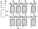
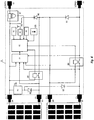
- FIG. 1 the general structure of the photovoltaic panel monitoring system built based on the module that monitors 2 operating parameters of a single photovoltaic panel 1 is shown.
- the photovoltaic panel 1 is connected to monitoring module 2 by means of contacts 40 and 41.
- the monitoring modules 2 of each individual photovoltaic panel 1 are connected in series and connected to the energy converter 3 by means of contacts 42 and 43.
- Each monitoring module 2 is wireless-connected to the network coordinator 20 which uses the antenna 4 for wireless communication with data transmission and visualization system.
- Antenna 33 of the monitoring module 2 is used for wireless communication.
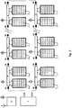
- the monitoring module for to panels 5 is connected to two photovoltaic panels 1 by means of contacts 94 and 95, and 96 and 97, respectively.
- the monitoring modules 5 of each set of two photovoltaic panels 1 are connected in series and connected to the energy converter 3 by means of contacts 98 and 99.
- Each monitoring module 5 is wireless-connected to the network coordinator 20 which uses the antenna 4 for wireless communication with the data transmission and visualization system. Antenna 85 of the monitoring module 5 is used for wireless communication.
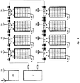
- Fig. 3 shows an embodiment of the monitoring system for eight panels, using monitoring modules 2 dedicated to a single monitoring module 1, in order to present the method of message transmission between devices.
- the photovoltaic panel 1.01 is connected to the panel operation monitoring module 2.01 which by means of contact 42 is connected to the energy converter 3, and by means of contact 43 to neighbouring monitoring module 2.02.
- the next photovoltaic panel 1.02 is connected to the monitoring module 2.02, and via contacts 42 and 43 is connected to neighbouring monitoring modules 2.01 and 2.03, and then to next modules.
- the photovoltaic panel 1.08 is connected to the monitoring module 2.08, which is connected to the energy converter 3 and the monitoring module 2.07.
- Monitoring modules 2.01, 2.02, 2.03, 2.04, 2.05, 2.05, 2.07, 2.08 are wireless-connected to the network coordinator 20 which performs the function of a wireless network operation coordinator, using the antenna 33 for communication with the coordinator, and antenna 4 for communication with the data transmission and visualization system.
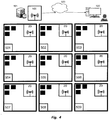
- Fig. 4 shows a diagram of photovoltaic farm in which the number of photovoltaic panels exceeds the number of panels connectable in a single wireless communication network. In this embodiment is has been assumed that it is up to 400 panels in one subnetwork.
- Fig. 4 shown 9 communication subsystems, designated as 501 through 509, each of which has its own network coordinator 20.
- the layout and definition of network parameters are developed at the system design stage, during which developed is the network configuration for each monitoring modules 2 or 5 is developed according to Fig. 5 and Fig. 6 respectively, taking into account physical location and electrical connection between individual panels.
- the planning of the structure of system elements also concerns the selection of basic radio channels for the network. The following settings were used for Fig. 4 :
- the measurement data are transmitted from monitoring subsystems to the data processing system 521 via the communication module 520, using the link of the master module 20 with communication by means of antenna 4. Then, the data from the processing system processing system 521 are transmitted by means of the communication infrastructure 520 to 523, and then to the end user 522, or directly from the processing system 521 to the end user 522.
- the data in the system are transmitted in both directions:
- the main system element is the microcontroller 31 which ensures the conversion of measurement signals from the voltage measuring circuit 37 and the current measuring circuit 38, controlling the execution key circuit 36, connected to the wireless communication module 32, connected to the short-range wireless communication module 34, and also optical signalling 35, and the temperature sensor 44.
- the monitoring module 2 also has an integrated antenna 33 connected to the wireless communication module 32.
- An important element of the monitoring module 2 is also the bypass diode 39 connected via contacts 42 and 43 to the neighbouring monitoring module 2 of photovoltaic panel 1 and energy converter 3.
- connection of the monitoring module 2 to the photovoltaic panel 1 by means of contacts 40 and 41 allows the power supply from energy generated by the photovoltaic panel 1.
- the power supply circuit 30 provides voltage to the monitoring module 2, and the execution key circuit 36 has a dedicated power supply system for a correct control of the panel disconnection key.
- the key control logic is independent of the control of execution key 36 of disconnection of the photovoltaic panel 1 by the microcontroller 31. If the microcontroller 31 is damaged or hangs, the execution key circuit 36 remains functional, i.e. it does not limit the power generation by photovoltaic panel 1.
- the microcontroller 31 circuit After activation, the microcontroller 31 circuit first reads the configuration from the short-range wireless communication module 34, and then starts the wireless communication using the wireless communication module 32, waiting for wireless communication to be established with neighbouring monitoring modules 2 and 20. When the radio communication established, the monitoring module 2 synchronizes its internal clock, thus allowing a transition to synchronous operation in the wireless communication and commencement of measurements according to the same timestamps for all monitoring modules.
- the microcontroller 31 measures current and voltage and records them in its internal memory according to timestamps generated by the network coordinator 20.
- the means of such measurements are stored in the internal memory as ready for transmission and await an appropriate control signal from the network coordinator 20 to supplement data in the measurement frame transported from the monitoring module 2 to the network coordinator 20.
- Optical signalling 35 is controlled from the microcontroller 31 based on the status of monitoring module 2, status of monitored photovoltaic panel 1, and also wireless-transmitted signals from the network coordinator 20.
- monitoring module 2 It is also possible to execute the monitoring module 2 to perform only the monitoring of photovoltaic panel 1 without the possibility of disconnecting it. Such a monitoring module 2 does not have the execution key circuit 36.
- the monitoring module for two panels 5 shown in Fig. 6 has a power supply circuit 80 which converts voltage from one or two photovoltaic panels 1, depending on the number and working order of photovoltaic panels, to the Vcc voltage for the monitoring module for two panels 5.
- the power supply to monitoring module 5 requires that at least one of the two panels operates correctly.
- the Vcc voltage is supplied to the microcontroller 82, voltage measuring circuits 81, and the current measuring circuit 87, temperature sensor 100, wireless communication module 84, and short-range wireless communication module 83 NFC.
- the main system element is the microcontroller 82 which ensures the conversion of measurement signals from the voltage measuring circuit 81 and the current measuring circuit 87, connected to the short-range wireless communication module 83 NFC, to the wireless communication module 84, optical signalling 86, temperature sensor 100, controlling two independent execution key circuits 88 and 89.
- the execution key circuits are optional. There are versions of monitoring modules without the panel disconnection option; in such case the elements of execution key circuits are not installed on the PCB.
- the monitoring module for two panels 5 according to Fig. 6 also has an integrated antenna 85 connected to the wireless communication module 84.
- the monitoring module for two panels has two bypass diodes 90 and 91, connected to the outputs of monitored photovoltaic panels 1. Connection of photovoltaic panel 1 to contacts 94 and 95 or 96 and 97 allows power supply from the energy generated by the panel or panels.
- the power supply circuit 80 provides voltage to elements of the monitoring module, while the execution key circuits 88 and 89 have a dedicated power supply system for a correct control of the panel disconnection key.
- the key control logic is independent of the control of execution key circuits 88 and 89 of panel disconnection by the microcontroller 82. If the microcontroller 82 is damaged or hangs, the execution key circuits 88 and 89 remain functional, i.e. they do not limit the power generation by photovoltaic panel which is in worse working order. It is also possible to execute the monitoring module 5 to perform only the monitoring of photovoltaic panel 1 without the possibility of disconnecting it.
- Such a monitoring module 5 does not have the execution key circuit 89.
- the communication configuration and panel identification data are entered at the configuration and/or system commission stage, using tools that allow data input to monitoring modules 2 or monitoring modules for two panels 5 by means of the short-range wireless communication module 34 NFC or the wireless communication module 32 used by the microcontroller 31 in the service mode. Communication in the service mode takes place directly between the service module, i.e. the device that allows the transmission of parameter set to the monitoring module using the wireless communication module 32.
- network cycle - time between two starts of data transmission in the wireless network reserved for the communication frame transfer from the master module to a network device and its return to the master module, taking the repetitions into account, time slot - time interval dedicated for data transmission by one monitoring module, e.g. module 2.01, jitter - time dispersion resulting from inaccuracy of time measurement by monitoring modules 2.01 through 2.08 and by the network coordinator 20, frame time - time necessary for data transmission, resulting from transmission speed, amount of sent data, and additional variables sent, e.g. a preamble
- the system configuration includes the entering of basic network parameters, in particular:
- the monitored panel data are entered (e.g. serial number, physical location), which allows finding the device and reading the identification parameters.
- Fig. 7 , Fig. 8 and Fig. 9 show a general data transmission principle, time relationships for data transmission methods and sequence of steps implemented for two-way transmission of messages in the wireless network.
- the embodiment relates to the network according to Fig. 3 consisting of monitoring modules 2.01, 2.02, 2.03, 2.04, 2.05, 2.06. 2.07 and 2.08 and the network coordinator 20.
- Data transmission is implemented in a linear network according to Fig. 7 in which each network element should participate in transmission of data.
- Each device has a permanently assigned logical address in the wireless network, entered at the device configuration stage.
- the data are transmitted between monitoring modules 2 and the network coordinator 20 in the order corresponding to their logical addresses which in turn result from their physical location.
- Logical addresses of devices are chosen in such a manner that modules with successive logical addresses are located next to each other in order to minimize the distance between monitoring modules 2 and increase the resistance to communication interference between the devices.
- the data are transmitted in both network directions:
- the data transmission is implemented with the use of a protocol based on continuous time synchronization between the monitoring modules 2.01, 2.02 through 2.08 and the time of network coordinator 20.
- the time slot length for data transmission through individual devices results from the length of data packets with reserve for jitter connected with time determination errors for start of transmission and listening by modules that participate in the wireless network communication.
- Each device receives at least one 1 time slot in the network communication, i.e. a slot in the FORWARD PHASE and a slot in the BACKWARD PHASE.
- the network coordinator 20 starts transmission in the first slot of the network cycle - SLOT F1 in the FORWARD phase, each successive monitoring module 2.01 through 2.08 has access to the time slot according to its logical address in the linear network.
- the monitoring module 2.01 receives SLOT F2
- module 2.02 receives SLOT F3
- module 2.03 receives SLOT F4
- module 2.04 receives SLOT F5
- module 2.05 receives SLOT F6
- module 2.07 receives SLOT F8.
- the communication frame contains synchronization data and data on data identifiers and data amounts which will be sent to the coordinator in the BACKWARD phase.
- the listening for frames transmitted from the network coordinator 20 or monitoring modules 2.01, 2.02 through 2.08 takes place in the beginning of the module operation or after occurrence of a communication error, in the mode without synchronization, i.e. each device listens for a communication frame.
- the frame reception synchronizes the time between the device that received the frame and the timestamp sent in the wireless communication from the network coordinator. Obtaining of timestamps causes a transfer to synchronous operation.
- the message transmission in network cycle starts by sending a frame in the FORWARD direction in which the coordinator records information to successive devices in the network that include identifiers of variables which are to be sent back to the coordinator in the BACKWARD frame.
- the wireless transmission of the information on expected data from the coordinator to measuring modules in the FORWARD phase causes that expected data are transmitted in the BACKWARD frame of the same network cycle.
- the devices After the expiry of time in which the BACKWARD phase starts, the devices start sending messages in time slots allotted to them, entering measurement values to the communication frame, in relevant fields; the details can be seen in Fig. 8 and Fig. 9 .
- the number of listening devices is limited to four neighbouring the monitoring module, meaning that for SLOT F1 where the sending device is the network coordinator 20, the listening devices are modules with logical addresses, i.e. monitoring module 2.01, monitoring module 2.02, monitoring module 2.03, and monitoring module 2.04. Reception of data by the monitoring module 2.01 in time SLOT F1 causes their transmission to next monitoring modules 2 in time SLOT F2 in which the listening devices are monitoring module 2.02, monitoring module 2.03, monitoring module 2.04, and monitoring module 2.05. The situation is repeated in successive time slots: SLOT F3, SLOT F4.
- time SLOT F5 the data are transmitted by the monitoring module 2.05, and there are only 3 listening devices due to the number of all devices in the network: monitoring module 2.06, monitoring module 2.07, monitoring module 2.08.
- monitoring module 2.06 monitoring module 2.07
- monitoring module 2.08 there are only two listening devices, i.e. monitoring modules 2.07 and 2.08, and in SLOT F7 the only listening device is monitoring module 2.08. It is allowed to assign a few time slots for end elements in the network in order not to lose the information transmission redundancy.
- the frame transfer through all network elements in provided time slots cause that the data are supplemented in the data buffer transmitted among successive measuring modules.
- the frame supplementing method is shown in detail in Fig. 9 .
- the monitoring module 2.08 sends the frame with prepared fields for voltage data from modules 2.01 through 2.08 and only the value from the monitoring module 2.08 is supplemented, the frame is correctly read by monitoring modules 2.07, 2.06, 2.05, 2.04.
- the frame sent by the monitoring module 2.06 has only its own supplemented data and the supplemented data from the monitoring module 2.08; the data from the monitoring module 2.07 are not supplemented.
- the frame from the monitoring module 2.06 was heard only by monitoring modules 2.04, 2.03, 2.02.
- the frame sent by the monitoring module 2.05 has only the supplemented data from monitoring modules 2.05 and 2.08; it does not have data from monitoring modules 2.06 and 2.07.
- the frame sent by the monitoring module 2.04 has the supplemented data from monitoring module 2.04 and the data which were sent earlier from monitoring modules 2.06, 2.07, 2.08.
- the network coordinator 20 Having received the data, the network coordinator 20 has a communication frame with the supplemented all voltage-relating data in these modules.
- the current-relating data, and also the data and commands from the network coordinator 20 to network modules 2.01 through 2.08 are supplemented in an analogous manner.
Landscapes
- Engineering & Computer Science (AREA)
- Power Engineering (AREA)
- Photovoltaic Devices (AREA)
- Remote Monitoring And Control Of Power-Distribution Networks (AREA)
Claims (7)
- Ein Verfahren zur Überwachung und Optimierung des Betriebs eines Satzes von Photovoltaikmodulen (1), das die Erkennung und Prognostizierung von Schäden ermöglicht und die folgenden Schritte umfasst:Bereitstellung von Überwachungsmodulen (2), die an Photovoltaikmodule (1) angeschlossen sind und von diesen mit Strom versorgt werden, sowie einer Netzwerksteuerung (20), wobei die Überwachungsmodule (2) drahtlos miteinander und mit der Netzwerksteuerung (20) kommunizieren können;Zuweisen einer logischen Adresse zu jedem Überwachungsmodul (2), so dass Module mit aufeinanderfolgenden logischen Adressen nebeneinander angeordnet sind;Zuweisen eines initialen Zeitfensters an die Netzwerksteuerung (20);Zuweisen eines Zeitfensters zu jedem Überwachungsmodul (2) mit Ausnahme des Überwachungsmoduls mit der letzten logischen Adresse, zwecks Vorwärtsübertragung entsprechend der logischen Adresse;Zuweisen eines Zeitfensters für die Rückwärtsübertragung zu jedem Überwachungsmodul (2) entsprechend der logischen Adresse;Für jedes der Überwachungsgeräte (2) und die Netzwerksteuerung (20) wird ein Gruppe von Geräten unter den Überwachungsgeräten (2) und/oder der Netzwerksteuerung (20) abgegrenzt, die dem jeweiligen Überwachungsgerät (2) oder der Netzwerksteuerung (20) unterstellt sind, zu einer Reihe von Geräten neben dem genannten Überwachungsgerät (2) oder der Netzwerksteuerung (20);In dem initialen Zeitfenster sendet die Netzwerksteuerung (20) ein Kommunikationsframe, das Synchronisationsdaten und Datenkennungen enthält, die an die Netzwerksteuerung (20) zurückgesendet werden sollen, und empfängt das Kommunikationsframe mittels der Überwachungsgeräte (2) im Rahmen der Reihe von Geräten, die der Netzwerksteuerung (20) unterstellt sind;In jedem nachfolgenden Zeitfenster für die Vorwärtsübertragung sendet das Überwachungsgerät (2), dem das jeweilige Zeitfenster für die Vorwärtsübertragung zugeteilt wurde, das Kommunikationsframe und empfängt das Kommunikationsframe durch Überwachungsgeräte (2) in der Reihe von Geräten, die dem jeweiligen Überwachungsgerät (2) unterstellt sind;In jedem nachfolgenden Zeitfenster für die Rückwärtsübertragung gibt das Überwachungsgerät (2), dem dieser Zeitrahmen für die Rückwärtsübertragung zugewiesen wurde, die Messwerte in das Kommunikationsframe ein, die den Datenkennungen entsprechen, und empfängt das Kommunikationsframe durch die Überwachungsgeräte (2) und/oder die Netzwerksteuerung (20) in der Reihe von Geräten, die dem jeweiligen Überwachungsgerät (2) unterstellt sind.
- Das Überwachungsverfahren nach Anspruch 1, wobei die Überwachungsmodule (2) entsprechend konfiguriert sind, indem ihnen ein grundlegender Funkbetriebskanal, eine Übertragungsleistung, eine Netzwerknummer und die Nummer des entsprechenden Subnetzwerks innerhalb des jeweiligen Netzwerks zugewiesen werden.
- Das Überwachungsverfahren nach Anspruch 1, wobei die Netzwerk-steuerung (20) Daten speichert, die den physischen Standortbestimmung eines bestimmten Überwachungsmoduls (2) freigeben, dessen logische Adresse bekannt ist.
- Ein System zur Überwachung und Optimierung des Betriebs von Photovoltaikmodulen (1), bestehend aus:Überwachungsgeräten (2), die über Kontaktpunkte (40, 41) mit Photovoltaikmodulen (1) verbunden und von diesen (30) mit Strom versorgt werden, ausgestattet mit einer Kommunikationsantenne (33);einer Netzwerksteuerung (20), die mit einer Antenne (33) ausgestattet ist;wobei die Überwachungsgeräte (2) so konfiguriert sind, dass sie drahtlos miteinander und mit der Netzwerksteuerung (20) über die Antennen kommunizieren (33);wobei die Überwachungsmodule (2) einen Spannungsmesskreis (37) und einen Strommesskreis (38) sowie einen Mikrocontroller (31) umfassen, der mit einer Speichereinheit ausgestattet ist, die so konfiguriert ist, dass bis zur erfolgreichen Übertragung Daten gespeichert werden;dadurch gekennzeichnet, dass die Netzwerksteuerung (20) und die Überwachungsmodule (2) entsprechend konfiguriert sind, um das Verfahren nach Anspruch 1 durchzuführen.
- Das Überwachungsverfahren nach Anspruch 4, wobei mindestens ein Überwachungsmodul (5) für die Überwachung von zwei Photovoltaik-Modulen (1) konfiguriert ist.
- Das Überwachungsverfahren nach Anspruch 4, wobei die Konfiguration der Überwachungsmodule (2) mindestens die Zuordnung eines grundlegenden Funkbetriebskanals, einer Übertragungsleistung, einer Netzwerknummer und einer Nummer eines entsprechenden Subnetzwerks innerhalb des jeweiligen Netzwerks zugewiesen werden.
- Das Überwachungsverfahren nach Anspruch 4, wobei die Netzwerksteuerung (20) für die Speicherung von Daten konfiguriert ist, die die physischen Standortbestimmung eines bestimmten Überwachungsmoduls (2) ermöglichen, dessen logische Adresse bekannt ist.
Priority Applications (1)
| Application Number | Priority Date | Filing Date | Title |
|---|---|---|---|
| PL18460030T PL3407465T3 (pl) | 2017-05-27 | 2018-05-21 | Sposób i system monitorowania i optymalizacji pracy zestawu paneli fotowoltaicznych |
Applications Claiming Priority (1)
| Application Number | Priority Date | Filing Date | Title |
|---|---|---|---|
| PL421741A PL232507B1 (pl) | 2017-05-27 | 2017-05-27 | Sposób i system monitorowania i optymalizacji pracy zestawu paneli fotowoltaicznych |
Publications (2)
| Publication Number | Publication Date |
|---|---|
| EP3407465A1 EP3407465A1 (de) | 2018-11-28 |
| EP3407465B1 true EP3407465B1 (de) | 2020-06-24 |
Family
ID=62555007
Family Applications (1)
| Application Number | Title | Priority Date | Filing Date |
|---|---|---|---|
| EP18460030.2A Active EP3407465B1 (de) | 2017-05-27 | 2018-05-21 | Verfahren und system zur überwachung und optimierung des betriebs einer gruppe von solarpanelen |
Country Status (3)
| Country | Link |
|---|---|
| EP (1) | EP3407465B1 (de) |
| ES (1) | ES2831498T3 (de) |
| PL (2) | PL232507B1 (de) |
Cited By (1)
| Publication number | Priority date | Publication date | Assignee | Title |
|---|---|---|---|---|
| DE102021130817A1 (de) | 2021-11-24 | 2023-05-25 | Wavelabs Solar Metrology Systems Gmbh | Energieautarke PV-Kennlinienmesssung |
Families Citing this family (7)
| Publication number | Priority date | Publication date | Assignee | Title |
|---|---|---|---|---|
| EP3780403B1 (de) * | 2018-03-30 | 2024-01-31 | Zeon Corporation | Leistungsverdrahtungs-netzwerkvorrichtung |
| EP3780402B1 (de) * | 2018-03-30 | 2025-10-08 | Zeon Corporation | Stromverteilungsnetzvorrichtung |
| CN110783927B (zh) * | 2019-10-12 | 2021-02-05 | 许继集团有限公司 | 多时间尺度交直流配电网调度方法及装置 |
| CN119420681A (zh) * | 2021-07-02 | 2025-02-11 | 国能智深控制技术有限公司 | 一种光伏电站的通信系统 |
| CN114966278B (zh) * | 2022-05-25 | 2025-08-08 | 山东明科电气技术有限公司 | 一种储能系统性能测试方法及装置 |
| CN117239946B (zh) * | 2023-09-20 | 2024-08-23 | 厦门矿通科技有限公司 | 一种应用于光伏电站的大规模光伏组件的智能监测系统 |
| CN118897556B (zh) * | 2024-10-09 | 2024-12-17 | 深圳南瑞科技有限公司 | 一种光伏组件故障导航纠偏方法及系统 |
Family Cites Families (4)
| Publication number | Priority date | Publication date | Assignee | Title |
|---|---|---|---|---|
| US8204709B2 (en) * | 2005-01-18 | 2012-06-19 | Solar Sentry Corporation | System and method for monitoring photovoltaic power generation systems |
| EP2230745A1 (de) * | 2009-03-18 | 2010-09-22 | SMA Solar Technology AG | Verfahren zur Fehlererkennung einer Energieerzeugungsanlage oder von Teilen einer Energieerzeugungsanlage, insbesondere einer PV-Anlage |
| JP5419018B2 (ja) * | 2010-06-14 | 2014-02-19 | 独立行政法人産業技術総合研究所 | スペクトル拡散通信システム |
| US20140266781A1 (en) * | 2013-03-12 | 2014-09-18 | Cool Earth Solar Inc. | Distributed wireless network for control systems |
-
2017
- 2017-05-27 PL PL421741A patent/PL232507B1/pl unknown
-
2018
- 2018-05-21 PL PL18460030T patent/PL3407465T3/pl unknown
- 2018-05-21 ES ES18460030T patent/ES2831498T3/es active Active
- 2018-05-21 EP EP18460030.2A patent/EP3407465B1/de active Active
Non-Patent Citations (1)
| Title |
|---|
| None * |
Cited By (1)
| Publication number | Priority date | Publication date | Assignee | Title |
|---|---|---|---|---|
| DE102021130817A1 (de) | 2021-11-24 | 2023-05-25 | Wavelabs Solar Metrology Systems Gmbh | Energieautarke PV-Kennlinienmesssung |
Also Published As
| Publication number | Publication date |
|---|---|
| PL421741A1 (pl) | 2018-12-03 |
| PL3407465T3 (pl) | 2020-12-28 |
| EP3407465A1 (de) | 2018-11-28 |
| PL232507B1 (pl) | 2019-06-28 |
| ES2831498T3 (es) | 2021-06-08 |
Similar Documents
| Publication | Publication Date | Title |
|---|---|---|
| EP3407465B1 (de) | Verfahren und system zur überwachung und optimierung des betriebs einer gruppe von solarpanelen | |
| CN109217471B (zh) | 低压配电台区网络拓扑的识别装置 | |
| US8044539B2 (en) | Intelligent solar energy collection system | |
| US20200077333A1 (en) | Sensor device and sensor network system | |
| CN104868846A (zh) | 基于无线物联网的太阳能光伏组件阵列数据采集方法 | |
| AU2013200542B2 (en) | Scalable packets in a frequency hopping spread spectrum (fhss) system | |
| Gomes et al. | WECO: A wireless platform for monitoring recycling point spots | |
| CN110676520A (zh) | 一种无线通信电池管理系统及其控制方法 | |
| CN113259892A (zh) | 一种无线数据采集系统 | |
| CN116039443B (zh) | 一种动力电池的无线监控系统及包括其的车辆 | |
| CN108923878B (zh) | 基于WiFi无线与GPS授时同步的传感器节点 | |
| CN114040372B (zh) | 一种基于中继节点的蓝牙Mesh网络远程抄表系统 | |
| AU2021269425B2 (en) | Low power cellular base station | |
| CN102095890A (zh) | 一种风力发电机组超声波风速风向测量装置 | |
| CN118945611A (zh) | 基于LoRa技术的煤矿顶底板无线传感器网络低功耗控制方法 | |
| Toma et al. | Self-powered high-rate wireless sensor network for underground high voltage power lines | |
| CN201812155U (zh) | 卫星同步从时钟装置 | |
| KR20150074526A (ko) | 기상정보 측정 및 수집 방법 및 시스템 | |
| CN213935175U (zh) | 电力组网系统 | |
| CN214410257U (zh) | 无线测温系统 | |
| CN114039975A (zh) | 一种基于去中心式节点的太阳能组件间通信系统和方法 | |
| CN212435946U (zh) | 综采工作面无线通信传输系统 | |
| CN103269127A (zh) | 通讯基站电源的远程监控系统和远程监控方法 | |
| KR20190023173A (ko) | 전기 에너지 통합 관리 시스템 및 그 관리 방법 | |
| CN223040154U (zh) | 基于无线通讯协议混合信标的室分网络监控系统 |
Legal Events
| Date | Code | Title | Description |
|---|---|---|---|
| PUAI | Public reference made under article 153(3) epc to a published international application that has entered the european phase |
Free format text: ORIGINAL CODE: 0009012 |
|
| STAA | Information on the status of an ep patent application or granted ep patent |
Free format text: STATUS: THE APPLICATION HAS BEEN PUBLISHED |
|
| AK | Designated contracting states |
Kind code of ref document: A1 Designated state(s): AL AT BE BG CH CY CZ DE DK EE ES FI FR GB GR HR HU IE IS IT LI LT LU LV MC MK MT NL NO PL PT RO RS SE SI SK SM TR |
|
| AX | Request for extension of the european patent |
Extension state: BA ME |
|
| STAA | Information on the status of an ep patent application or granted ep patent |
Free format text: STATUS: REQUEST FOR EXAMINATION WAS MADE |
|
| 17P | Request for examination filed |
Effective date: 20190528 |
|
| RBV | Designated contracting states (corrected) |
Designated state(s): AL AT BE BG CH CY CZ DE DK EE ES FI FR GB GR HR HU IE IS IT LI LT LU LV MC MK MT NL NO PL PT RO RS SE SI SK SM TR |
|
| GRAP | Despatch of communication of intention to grant a patent |
Free format text: ORIGINAL CODE: EPIDOSNIGR1 |
|
| STAA | Information on the status of an ep patent application or granted ep patent |
Free format text: STATUS: GRANT OF PATENT IS INTENDED |
|
| INTG | Intention to grant announced |
Effective date: 20200108 |
|
| GRAS | Grant fee paid |
Free format text: ORIGINAL CODE: EPIDOSNIGR3 |
|
| GRAA | (expected) grant |
Free format text: ORIGINAL CODE: 0009210 |
|
| STAA | Information on the status of an ep patent application or granted ep patent |
Free format text: STATUS: THE PATENT HAS BEEN GRANTED |
|
| RIN1 | Information on inventor provided before grant (corrected) |
Inventor name: SWIECH, MARCIN Inventor name: HANC, ARTUR |
|
| AK | Designated contracting states |
Kind code of ref document: B1 Designated state(s): AL AT BE BG CH CY CZ DE DK EE ES FI FR GB GR HR HU IE IS IT LI LT LU LV MC MK MT NL NO PL PT RO RS SE SI SK SM TR |
|
| REG | Reference to a national code |
Ref country code: GB Ref legal event code: FG4D |
|
| REG | Reference to a national code |
Ref country code: CH Ref legal event code: EP |
|
| REG | Reference to a national code |
Ref country code: AT Ref legal event code: REF Ref document number: 1284854 Country of ref document: AT Kind code of ref document: T Effective date: 20200715 |
|
| REG | Reference to a national code |
Ref country code: DE Ref legal event code: R096 Ref document number: 602018005579 Country of ref document: DE |
|
| REG | Reference to a national code |
Ref country code: IE Ref legal event code: FG4D |
|
| PG25 | Lapsed in a contracting state [announced via postgrant information from national office to epo] |
Ref country code: GR Free format text: LAPSE BECAUSE OF FAILURE TO SUBMIT A TRANSLATION OF THE DESCRIPTION OR TO PAY THE FEE WITHIN THE PRESCRIBED TIME-LIMIT Effective date: 20200925 Ref country code: FI Free format text: LAPSE BECAUSE OF FAILURE TO SUBMIT A TRANSLATION OF THE DESCRIPTION OR TO PAY THE FEE WITHIN THE PRESCRIBED TIME-LIMIT Effective date: 20200624 Ref country code: NO Free format text: LAPSE BECAUSE OF FAILURE TO SUBMIT A TRANSLATION OF THE DESCRIPTION OR TO PAY THE FEE WITHIN THE PRESCRIBED TIME-LIMIT Effective date: 20200924 Ref country code: SE Free format text: LAPSE BECAUSE OF FAILURE TO SUBMIT A TRANSLATION OF THE DESCRIPTION OR TO PAY THE FEE WITHIN THE PRESCRIBED TIME-LIMIT Effective date: 20200624 Ref country code: LT Free format text: LAPSE BECAUSE OF FAILURE TO SUBMIT A TRANSLATION OF THE DESCRIPTION OR TO PAY THE FEE WITHIN THE PRESCRIBED TIME-LIMIT Effective date: 20200624 |
|
| REG | Reference to a national code |
Ref country code: LT Ref legal event code: MG4D |
|
| PG25 | Lapsed in a contracting state [announced via postgrant information from national office to epo] |
Ref country code: BG Free format text: LAPSE BECAUSE OF FAILURE TO SUBMIT A TRANSLATION OF THE DESCRIPTION OR TO PAY THE FEE WITHIN THE PRESCRIBED TIME-LIMIT Effective date: 20200924 Ref country code: RS Free format text: LAPSE BECAUSE OF FAILURE TO SUBMIT A TRANSLATION OF THE DESCRIPTION OR TO PAY THE FEE WITHIN THE PRESCRIBED TIME-LIMIT Effective date: 20200624 Ref country code: HR Free format text: LAPSE BECAUSE OF FAILURE TO SUBMIT A TRANSLATION OF THE DESCRIPTION OR TO PAY THE FEE WITHIN THE PRESCRIBED TIME-LIMIT Effective date: 20200624 Ref country code: LV Free format text: LAPSE BECAUSE OF FAILURE TO SUBMIT A TRANSLATION OF THE DESCRIPTION OR TO PAY THE FEE WITHIN THE PRESCRIBED TIME-LIMIT Effective date: 20200624 |
|
| REG | Reference to a national code |
Ref country code: NL Ref legal event code: MP Effective date: 20200624 |
|
| REG | Reference to a national code |
Ref country code: AT Ref legal event code: MK05 Ref document number: 1284854 Country of ref document: AT Kind code of ref document: T Effective date: 20200624 |
|
| PG25 | Lapsed in a contracting state [announced via postgrant information from national office to epo] |
Ref country code: NL Free format text: LAPSE BECAUSE OF FAILURE TO SUBMIT A TRANSLATION OF THE DESCRIPTION OR TO PAY THE FEE WITHIN THE PRESCRIBED TIME-LIMIT Effective date: 20200624 Ref country code: AL Free format text: LAPSE BECAUSE OF FAILURE TO SUBMIT A TRANSLATION OF THE DESCRIPTION OR TO PAY THE FEE WITHIN THE PRESCRIBED TIME-LIMIT Effective date: 20200624 |
|
| PG25 | Lapsed in a contracting state [announced via postgrant information from national office to epo] |
Ref country code: PT Free format text: LAPSE BECAUSE OF FAILURE TO SUBMIT A TRANSLATION OF THE DESCRIPTION OR TO PAY THE FEE WITHIN THE PRESCRIBED TIME-LIMIT Effective date: 20201026 Ref country code: AT Free format text: LAPSE BECAUSE OF FAILURE TO SUBMIT A TRANSLATION OF THE DESCRIPTION OR TO PAY THE FEE WITHIN THE PRESCRIBED TIME-LIMIT Effective date: 20200624 Ref country code: IT Free format text: LAPSE BECAUSE OF FAILURE TO SUBMIT A TRANSLATION OF THE DESCRIPTION OR TO PAY THE FEE WITHIN THE PRESCRIBED TIME-LIMIT Effective date: 20200624 Ref country code: EE Free format text: LAPSE BECAUSE OF FAILURE TO SUBMIT A TRANSLATION OF THE DESCRIPTION OR TO PAY THE FEE WITHIN THE PRESCRIBED TIME-LIMIT Effective date: 20200624 Ref country code: SM Free format text: LAPSE BECAUSE OF FAILURE TO SUBMIT A TRANSLATION OF THE DESCRIPTION OR TO PAY THE FEE WITHIN THE PRESCRIBED TIME-LIMIT Effective date: 20200624 Ref country code: RO Free format text: LAPSE BECAUSE OF FAILURE TO SUBMIT A TRANSLATION OF THE DESCRIPTION OR TO PAY THE FEE WITHIN THE PRESCRIBED TIME-LIMIT Effective date: 20200624 Ref country code: CZ Free format text: LAPSE BECAUSE OF FAILURE TO SUBMIT A TRANSLATION OF THE DESCRIPTION OR TO PAY THE FEE WITHIN THE PRESCRIBED TIME-LIMIT Effective date: 20200624 |
|
| PG25 | Lapsed in a contracting state [announced via postgrant information from national office to epo] |
Ref country code: SK Free format text: LAPSE BECAUSE OF FAILURE TO SUBMIT A TRANSLATION OF THE DESCRIPTION OR TO PAY THE FEE WITHIN THE PRESCRIBED TIME-LIMIT Effective date: 20200624 Ref country code: IS Free format text: LAPSE BECAUSE OF FAILURE TO SUBMIT A TRANSLATION OF THE DESCRIPTION OR TO PAY THE FEE WITHIN THE PRESCRIBED TIME-LIMIT Effective date: 20201024 |
|
| REG | Reference to a national code |
Ref country code: DE Ref legal event code: R097 Ref document number: 602018005579 Country of ref document: DE |
|
| PG25 | Lapsed in a contracting state [announced via postgrant information from national office to epo] |
Ref country code: DK Free format text: LAPSE BECAUSE OF FAILURE TO SUBMIT A TRANSLATION OF THE DESCRIPTION OR TO PAY THE FEE WITHIN THE PRESCRIBED TIME-LIMIT Effective date: 20200624 |
|
| PLBE | No opposition filed within time limit |
Free format text: ORIGINAL CODE: 0009261 |
|
| STAA | Information on the status of an ep patent application or granted ep patent |
Free format text: STATUS: NO OPPOSITION FILED WITHIN TIME LIMIT |
|
| 26N | No opposition filed |
Effective date: 20210325 |
|
| REG | Reference to a national code |
Ref country code: ES Ref legal event code: FG2A Ref document number: 2831498 Country of ref document: ES Kind code of ref document: T3 Effective date: 20210608 |
|
| PG25 | Lapsed in a contracting state [announced via postgrant information from national office to epo] |
Ref country code: SI Free format text: LAPSE BECAUSE OF FAILURE TO SUBMIT A TRANSLATION OF THE DESCRIPTION OR TO PAY THE FEE WITHIN THE PRESCRIBED TIME-LIMIT Effective date: 20200624 |
|
| REG | Reference to a national code |
Ref country code: CH Ref legal event code: PL |
|
| PG25 | Lapsed in a contracting state [announced via postgrant information from national office to epo] |
Ref country code: CH Free format text: LAPSE BECAUSE OF NON-PAYMENT OF DUE FEES Effective date: 20210531 Ref country code: LU Free format text: LAPSE BECAUSE OF NON-PAYMENT OF DUE FEES Effective date: 20210521 Ref country code: MC Free format text: LAPSE BECAUSE OF FAILURE TO SUBMIT A TRANSLATION OF THE DESCRIPTION OR TO PAY THE FEE WITHIN THE PRESCRIBED TIME-LIMIT Effective date: 20200624 Ref country code: LI Free format text: LAPSE BECAUSE OF NON-PAYMENT OF DUE FEES Effective date: 20210531 |
|
| REG | Reference to a national code |
Ref country code: BE Ref legal event code: MM Effective date: 20210531 |
|
| PG25 | Lapsed in a contracting state [announced via postgrant information from national office to epo] |
Ref country code: IE Free format text: LAPSE BECAUSE OF NON-PAYMENT OF DUE FEES Effective date: 20210521 |
|
| PG25 | Lapsed in a contracting state [announced via postgrant information from national office to epo] |
Ref country code: FR Free format text: LAPSE BECAUSE OF NON-PAYMENT OF DUE FEES Effective date: 20210531 |
|
| PG25 | Lapsed in a contracting state [announced via postgrant information from national office to epo] |
Ref country code: BE Free format text: LAPSE BECAUSE OF NON-PAYMENT OF DUE FEES Effective date: 20210531 |
|
| PGFP | Annual fee paid to national office [announced via postgrant information from national office to epo] |
Ref country code: ES Payment date: 20220601 Year of fee payment: 5 |
|
| GBPC | Gb: european patent ceased through non-payment of renewal fee |
Effective date: 20220521 |
|
| PG25 | Lapsed in a contracting state [announced via postgrant information from national office to epo] |
Ref country code: GB Free format text: LAPSE BECAUSE OF NON-PAYMENT OF DUE FEES Effective date: 20220521 |
|
| PG25 | Lapsed in a contracting state [announced via postgrant information from national office to epo] |
Ref country code: CY Free format text: LAPSE BECAUSE OF FAILURE TO SUBMIT A TRANSLATION OF THE DESCRIPTION OR TO PAY THE FEE WITHIN THE PRESCRIBED TIME-LIMIT Effective date: 20200624 |
|
| PG25 | Lapsed in a contracting state [announced via postgrant information from national office to epo] |
Ref country code: HU Free format text: LAPSE BECAUSE OF FAILURE TO SUBMIT A TRANSLATION OF THE DESCRIPTION OR TO PAY THE FEE WITHIN THE PRESCRIBED TIME-LIMIT; INVALID AB INITIO Effective date: 20180521 |
|
| PGFP | Annual fee paid to national office [announced via postgrant information from national office to epo] |
Ref country code: PL Payment date: 20230518 Year of fee payment: 6 |
|
| PG25 | Lapsed in a contracting state [announced via postgrant information from national office to epo] |
Ref country code: MK Free format text: LAPSE BECAUSE OF FAILURE TO SUBMIT A TRANSLATION OF THE DESCRIPTION OR TO PAY THE FEE WITHIN THE PRESCRIBED TIME-LIMIT Effective date: 20200624 |
|
| PG25 | Lapsed in a contracting state [announced via postgrant information from national office to epo] |
Ref country code: TR Free format text: LAPSE BECAUSE OF FAILURE TO SUBMIT A TRANSLATION OF THE DESCRIPTION OR TO PAY THE FEE WITHIN THE PRESCRIBED TIME-LIMIT Effective date: 20200624 |
|
| REG | Reference to a national code |
Ref country code: ES Ref legal event code: FD2A Effective date: 20240628 |
|
| PG25 | Lapsed in a contracting state [announced via postgrant information from national office to epo] |
Ref country code: ES Free format text: LAPSE BECAUSE OF NON-PAYMENT OF DUE FEES Effective date: 20230522 |
|
| PG25 | Lapsed in a contracting state [announced via postgrant information from national office to epo] |
Ref country code: ES Free format text: LAPSE BECAUSE OF NON-PAYMENT OF DUE FEES Effective date: 20230522 |
|
| PG25 | Lapsed in a contracting state [announced via postgrant information from national office to epo] |
Ref country code: MT Free format text: LAPSE BECAUSE OF FAILURE TO SUBMIT A TRANSLATION OF THE DESCRIPTION OR TO PAY THE FEE WITHIN THE PRESCRIBED TIME-LIMIT Effective date: 20200624 |
|
| PG25 | Lapsed in a contracting state [announced via postgrant information from national office to epo] |
Ref country code: PL Free format text: LAPSE BECAUSE OF NON-PAYMENT OF DUE FEES Effective date: 20240521 |
|
| PGFP | Annual fee paid to national office [announced via postgrant information from national office to epo] |
Ref country code: DE Payment date: 20250529 Year of fee payment: 8 |