EP3407245A1 - Method and device for determining rotation angle of human face, and computer storage medium - Google Patents
Method and device for determining rotation angle of human face, and computer storage medium Download PDFInfo
- Publication number
- EP3407245A1 EP3407245A1 EP17740960.4A EP17740960A EP3407245A1 EP 3407245 A1 EP3407245 A1 EP 3407245A1 EP 17740960 A EP17740960 A EP 17740960A EP 3407245 A1 EP3407245 A1 EP 3407245A1
- Authority
- EP
- European Patent Office
- Prior art keywords
- facial feature
- location information
- symmetrical
- feature points
- module
- Prior art date
- Legal status (The legal status is an assumption and is not a legal conclusion. Google has not performed a legal analysis and makes no representation as to the accuracy of the status listed.)
- Granted
Links
- 238000000034 method Methods 0.000 title claims abstract description 109
- 230000001815 facial effect Effects 0.000 claims description 499
- 238000004364 calculation method Methods 0.000 claims description 83
- 230000008569 process Effects 0.000 description 27
- 238000010586 diagram Methods 0.000 description 24
- 230000006870 function Effects 0.000 description 12
- 238000005516 engineering process Methods 0.000 description 9
- 238000012545 processing Methods 0.000 description 8
- 210000003128 head Anatomy 0.000 description 7
- 238000004891 communication Methods 0.000 description 6
- 238000001514 detection method Methods 0.000 description 5
- 230000033001 locomotion Effects 0.000 description 4
- 230000003287 optical effect Effects 0.000 description 4
- 230000008878 coupling Effects 0.000 description 3
- 238000010168 coupling process Methods 0.000 description 3
- 238000005859 coupling reaction Methods 0.000 description 3
- 238000007726 management method Methods 0.000 description 3
- 230000001133 acceleration Effects 0.000 description 2
- 238000013500 data storage Methods 0.000 description 2
- 210000000056 organ Anatomy 0.000 description 2
- 230000005236 sound signal Effects 0.000 description 2
- NAWXUBYGYWOOIX-SFHVURJKSA-N (2s)-2-[[4-[2-(2,4-diaminoquinazolin-6-yl)ethyl]benzoyl]amino]-4-methylidenepentanedioic acid Chemical compound C1=CC2=NC(N)=NC(N)=C2C=C1CCC1=CC=C(C(=O)N[C@@H](CC(=C)C(O)=O)C(O)=O)C=C1 NAWXUBYGYWOOIX-SFHVURJKSA-N 0.000 description 1
- 238000004458 analytical method Methods 0.000 description 1
- 230000009286 beneficial effect Effects 0.000 description 1
- 230000005540 biological transmission Effects 0.000 description 1
- 230000008859 change Effects 0.000 description 1
- 238000004590 computer program Methods 0.000 description 1
- 238000007796 conventional method Methods 0.000 description 1
- 238000007599 discharging Methods 0.000 description 1
- 210000004709 eyebrow Anatomy 0.000 description 1
- 230000005484 gravity Effects 0.000 description 1
- 230000006698 induction Effects 0.000 description 1
- 239000004973 liquid crystal related substance Substances 0.000 description 1
- 230000007774 longterm Effects 0.000 description 1
- 238000010295 mobile communication Methods 0.000 description 1
- 238000012544 monitoring process Methods 0.000 description 1
- 238000003672 processing method Methods 0.000 description 1
- 239000007787 solid Substances 0.000 description 1
- 230000003068 static effect Effects 0.000 description 1
- 230000000007 visual effect Effects 0.000 description 1
Images


Classifications
-
- G—PHYSICS
- G06—COMPUTING; CALCULATING OR COUNTING
- G06V—IMAGE OR VIDEO RECOGNITION OR UNDERSTANDING
- G06V40/00—Recognition of biometric, human-related or animal-related patterns in image or video data
- G06V40/10—Human or animal bodies, e.g. vehicle occupants or pedestrians; Body parts, e.g. hands
- G06V40/16—Human faces, e.g. facial parts, sketches or expressions
- G06V40/161—Detection; Localisation; Normalisation
- G06V40/166—Detection; Localisation; Normalisation using acquisition arrangements
-
- G—PHYSICS
- G06—COMPUTING; CALCULATING OR COUNTING
- G06T—IMAGE DATA PROCESSING OR GENERATION, IN GENERAL
- G06T7/00—Image analysis
- G06T7/70—Determining position or orientation of objects or cameras
- G06T7/73—Determining position or orientation of objects or cameras using feature-based methods
-
- G—PHYSICS
- G06—COMPUTING; CALCULATING OR COUNTING
- G06F—ELECTRIC DIGITAL DATA PROCESSING
- G06F3/00—Input arrangements for transferring data to be processed into a form capable of being handled by the computer; Output arrangements for transferring data from processing unit to output unit, e.g. interface arrangements
- G06F3/01—Input arrangements or combined input and output arrangements for interaction between user and computer
- G06F3/011—Arrangements for interaction with the human body, e.g. for user immersion in virtual reality
- G06F3/012—Head tracking input arrangements
-
- G—PHYSICS
- G06—COMPUTING; CALCULATING OR COUNTING
- G06V—IMAGE OR VIDEO RECOGNITION OR UNDERSTANDING
- G06V40/00—Recognition of biometric, human-related or animal-related patterns in image or video data
- G06V40/10—Human or animal bodies, e.g. vehicle occupants or pedestrians; Body parts, e.g. hands
- G06V40/16—Human faces, e.g. facial parts, sketches or expressions
- G06V40/161—Detection; Localisation; Normalisation
- G06V40/165—Detection; Localisation; Normalisation using facial parts and geometric relationships
-
- G—PHYSICS
- G06—COMPUTING; CALCULATING OR COUNTING
- G06V—IMAGE OR VIDEO RECOGNITION OR UNDERSTANDING
- G06V40/00—Recognition of biometric, human-related or animal-related patterns in image or video data
- G06V40/10—Human or animal bodies, e.g. vehicle occupants or pedestrians; Body parts, e.g. hands
- G06V40/16—Human faces, e.g. facial parts, sketches or expressions
- G06V40/168—Feature extraction; Face representation
- G06V40/169—Holistic features and representations, i.e. based on the facial image taken as a whole
-
- G—PHYSICS
- G06—COMPUTING; CALCULATING OR COUNTING
- G06V—IMAGE OR VIDEO RECOGNITION OR UNDERSTANDING
- G06V40/00—Recognition of biometric, human-related or animal-related patterns in image or video data
- G06V40/10—Human or animal bodies, e.g. vehicle occupants or pedestrians; Body parts, e.g. hands
- G06V40/16—Human faces, e.g. facial parts, sketches or expressions
- G06V40/168—Feature extraction; Face representation
- G06V40/171—Local features and components; Facial parts ; Occluding parts, e.g. glasses; Geometrical relationships
-
- G—PHYSICS
- G06—COMPUTING; CALCULATING OR COUNTING
- G06T—IMAGE DATA PROCESSING OR GENERATION, IN GENERAL
- G06T2207/00—Indexing scheme for image analysis or image enhancement
- G06T2207/20—Special algorithmic details
- G06T2207/20016—Hierarchical, coarse-to-fine, multiscale or multiresolution image processing; Pyramid transform
-
- G—PHYSICS
- G06—COMPUTING; CALCULATING OR COUNTING
- G06T—IMAGE DATA PROCESSING OR GENERATION, IN GENERAL
- G06T2207/00—Indexing scheme for image analysis or image enhancement
- G06T2207/30—Subject of image; Context of image processing
- G06T2207/30196—Human being; Person
- G06T2207/30201—Face
Definitions
- the present disclosure relates to the field of facial recognition technologies, and in particular, to a method and an apparatus for determining a face rotation angle, and a computer storage medium.
- a facial recognition technology is to recognize a face image from an image shot by a video camera.
- the face When the video camera is shooting a face, the face performs a head motion such as head raising, head lowering, rotating to left or rotating to right.
- a head motion such as head raising, head lowering, rotating to left or rotating to right.
- an angle exists between a face in an image shot by the video camera and a face of a frontal face image, the angle is a face rotation angle
- the facial recognition technology needs to determine the face rotation angle in the image, and can recognize a face image from the image only according to the face rotation angle.
- a face rotation angle is determined by using the following method: a face is made to perform head motions in different rotation directions in advance, face images in the different rotation directions are shot by using a video camera, a texture feature of a face image in each rotation direction is analyzed separately, and each rotation direction is made to correspond to the texture feature of the face image in each rotation direction to form a correspondence.
- a face rotation angle of a face image needs to be determined, a texture feature of the face image is analyzed, a correspondence is searched for a texture feature most similar to the texture feature, a face rotation direction corresponding to the most similar texture feature is obtained, and the face rotation angle of the face image is estimated according to the face rotation direction and the texture feature.
- embodiments of the present invention provide a method and an apparatus for determining a face rotation angle, and a computer storage medium.
- the technical solutions are as follows:
- the embodiments of the present invention provide a method for determining a face rotation angle, including:
- the embodiments of the present invention further provide an apparatus for determining a face rotation angle, including:
- the embodiments of the present invention further provide a computer storage medium, the computer storage medium storing a computer executable instruction, and the computer executable instruction being used to perform the method for determining a face rotation angle according to the embodiments of the present invention.
- preset multiple pairs of symmetrical facial feature points and one first facial feature point are obtained; according to first location information of facial feature points included in each pair of facial feature points of the multiple pairs of facial feature points, first location information of a symmetrical midpoint of each pair of facial feature points is obtained; and a preset line segment ratio is calculated according to the first location information of the symmetrical midpoint of each pair of facial feature points and first location information of the first facial feature point, a correspondence between the preset line segment ratio and a face rotation angle is queried according to the line segment ratio, and the face rotation angle of the to-be-determined face image is determined, so as to resolve the problem that the face rotation angle cannot be determined. Because the correspondence between the preset line segment ratio and the face rotation angle is a relatively precise correspondence between a line segment ratio and an angle, the method for determining a face rotation angle provided in the embodiment of the present invention greatly improves precision of determining a face rotation angle.
- FIG. 1 is a flowchart of a method for determining a face rotation angle according to an embodiment of the present invention. Referring to FIG. 1 , the method includes the following steps.
- step 101 Obtain first location information of preset multiple facial feature points in a to-be-determined face image, a quantity of the multiple facial feature points being an odd number, the multiple facial feature points including multiple pairs of symmetrical facial feature points and one first facial feature point, and the multiple facial feature points being not coplanar.
- step 102 Obtain, according to first location information of facial feature points included in each pair of facial feature points of the multiple pairs of facial feature points, first location information of a symmetrical midpoint of each pair of facial feature points.
- step 200 Detect preset multiple facial feature points in a to-be-determined face image.
- the preset multiple facial feature points are selected from points that are easily recognized in a face, and a preset facial feature point is located on a contour of a facial organ, and may be a turning point of the contour of the facial organ.
- a preset feature point may be an inner eye corner, an outer eye corner, a mouth corner, the tail of a brow, the head of a brow, or a nasal tip, both the inner eye corner and the outer eye corner are turning points of a contour of an eye
- the mouth corner is a turning point of a contour of a mouth
- the tail of the brow and the head of the brow are turning points of a contour of an eyebrow
- the nasal tip is a turning point of a contour of a nose.
- a quantity of the preset multiple facial feature points is an odd number.
- the quantity may be 5 or 7
- the preset multiple facial feature points include multiple pairs of symmetrical facial feature points and one remaining first facial feature point, and the multiple facial feature points are not coplanar.
- the multiple facial feature points may include five facial feature points, and the five facial feature points include a first pair of symmetrical facial feature points, a second pair of symmetrical facial feature points, and one remaining first facial feature point.
- the first pair of symmetrical facial feature points may be two inner eye corners
- the second pair of symmetrical facial feature points may be two mouth corners
- the remaining first facial feature point is a nasal tip.
- This step may be: first, a face in the to-be-determined face image is detected by using a face detection technology, and then the first pair of symmetrical facial feature points, that is, the two inner eye corners, the second pair of symmetrical facial feature points, that is, the two mouth corners, and the remaining first facial feature point, that is, the nasal tip are detected in the face by using a facial feature point detection technology.
- FIG. 2B is a diagram of tagging feature points in a to-be-determined face image according to this embodiment (where the feature points in the figure not only include detected facial feature points, but also include a symmetrical midpoints formed by detected symmetrical facial feature points and another point, and are described in the following content). As shown in FIG.
- step 201 Obtain first location information of preset multiple facial feature points in a to-be-determined face image.
- a facial feature point After a facial feature point is detected, coordinates of the facial feature point are automatically obtained, where a coordinate form of the facial feature point is ( x, y ) , and coordinates after positioning are output to a terminal. In this way, the terminal may directly obtain a coordinate location of the facial feature point after positioning.
- coordinate locations obtained by the terminal of the preset first pair of symmetrical facial feature points are separately C' ( x 1 , y 1 ) and D' ( x 2 , y 2 )
- coordinate locations obtained by the terminal of the second pair of symmetrical facial feature points are separately E' ( x 3 , y 3 ) and F' ( x 4 , y 4 )
- a coordinate location obtained by the terminal of the remaining first facial feature point (the nasal tip) is N' ( x 5 , y 5 ).
- the obtained coordinate locations of the five facial feature points are separately: C' (0, 0), D' (2, 2), E' (1, -2), F' (2, -1), and N' (1.5, 0).
- the first location information of the first symmetrical midpoint of the first pair of symmetrical facial feature points is A' (1, 1).
- step 203 Obtain first location information of a second symmetrical midpoint of the second pair of symmetrical facial feature points according to first location information of each facial feature point included in the second pair of symmetrical facial feature points.
- the face rotation angle of the to-be-determined face image may be the face pitch angle or a face lateral rotation angle.
- a method for determining a face pitch angle and a method for determining a face lateral rotation angle are separately described below.
- the face pitch angle of the to-be-determined face image is determined according to the first location information of the symmetrical midpoint of each pair of facial feature points and first location information of the first facial feature point. Referring to FIG. 2C , the method may include the following steps.
- step 204a Calculate a length of a first line segment formed by the first symmetrical midpoint and the first facial feature point according to the first location information of the first symmetrical midpoint and the first location information of the first facial feature point.
- step 204b Calculate a length of a second line segment formed by the second symmetrical midpoint and the first facial feature point according to the first location information of the second symmetrical midpoint and the first location information of the first facial feature point.
- the first ratio of the length A'N' of the first line segment to the length B'N' of the second line segment is calculated, a pre-established correspondence between the first ratio and the face pitch angle is queried according to the first ratio (for a process of establishing the correspondence, refer to the following steps 302a to 302e), and the face pitch angle corresponding to the calculated first ratio is queried from the correspondence, and the face pitch angle is determined as the face pitch angle of the to-be-determined face image.
- a first ratio closest to the first ratio calculated in this step is determined from all the first ratios in the correspondence, and then a face pitch angle corresponding to the closest first ratio is used as the face pitch angle corresponding to the first ratio calculated in this step.
- Subtraction is performed on each first ratio included in the pre-established correspondence between the first ratio and the face pitch angle and the first ratio calculated in this step, to obtain a first ratio difference, then an absolute value operation is performed on each first ratio difference, values obtained after the absolute value operation are compared, to obtain a minimum absolute value, then a first ratio corresponding to the minimum absolute value (a a first ratio included in the correspondence between the first ratio and the face pitch angle) is obtained, and the first ratio is determined as the first ratio closest to the first ratio calculated in this step.
- step 205 Determine a face lateral rotation angle of the to-be-determined face image according to the first location information of the symmetrical midpoint of each pair of facial feature points and first location information of the first facial feature point.
- the face lateral rotation angle of the to-be-determined face image is determined according to the first location information of the symmetrical midpoint of each pair of facial feature points, the first location information of the first facial feature point, and the face pitch angle that is determined by using the foregoing process.
- the method may include the following steps.
- step 205a Calculate a first vertical distance from the first facial feature point to a third line segment and a length of the third line segment according to the first location information of the first symmetrical midpoint, the first location information of the second symmetrical midpoint, and the first location information of the first facial feature point.
- the first location information of the first symmetrical midpoint is A' ( x 6 , y 6 ). It can be learned from step 203 that, the first location information of the second symmetrical midpoint is B' ( x 7 , y 7 ). It can be learned from step 201 that, the first location information of the first facial feature point is N' ( x 5 , y 5 ).
- the third line segment is a line segment A'B' formed by the first symmetrical midpoint A' ( x 6 , y 6 ) and the second symmetrical midpoint B' ( x 7 , y 7 ), and the first vertical distance from the first facial feature point to the third line segment is calculated by using the following method: first, a straight line passing through the point A' and the point B' is tagged as a straight line c, a general straight-line equation of the straight line c is calculated according to the first location information of the point A' and the point B', and then a first vertical distance from the first facial feature point N' to the straight line c is calculated according to the first location information of the first facial feature point N'. Details are as follows:
- the straight line c passing through the point A' ( x 6 , y 6 ) and the point B' ( x 7 , y 7 ) may be further calculated by using another method, and details are not described herein.
- the straight line c is a straight line passing through the point A' ( x 6 , y 6 ) and the point B' ( x 7 , y 7 )
- the distance d from the first facial feature point N' ( x 5 , y 5 ) to the straight line c is a second vertical distance from the first facial feature point N' ( x 5 , y 5 ) to the third line segment A'B'. Therefore, the first vertical distance is the distance d.
- step 205b Obtain, according to the face pitch angle and from a correspondence between the face pitch angle and a third ratio, the corresponding third ratio.
- a pre-established correspondence between a third ratio and a face pitch angle is queried according to the face pitch angle determined in step 204 (for a process of establishing the correspondence, refer to subsequent steps 303a to 303f), a third ratio corresponding to a face pitch angle is queried from the correspondence, the face pitch angle is the face pitch angle determined in step 204, and the third ratio is tagged as e.
- a face pitch angle closest to the face pitch angle calculated in step 204 is determined from all the face pitch angles, and then a third ratio corresponding to the closest face pitch angle is used as the third ratio corresponding to the face pitch angle.
- Subtraction is performed on each face pitch angle included in the pre-established correspondence between the third ratio and the face pitch angle and the face pitch angle determined in step 204, to obtain a face pitch angle difference, then an absolute value operation is performed on each face pitch angle difference, values obtained after the absolute value operation are compared, to obtain a minimum absolute value, then a face pitch angle corresponding to the minimum absolute value (a face pitch angle included in the correspondence between the third ratio and the face pitch angle) is obtained, and the face pitch angle is determined as the face pitch angle closest to the face pitch angle calculated in step 204.
- step 205c Calculate the length of the fourth line segment according to the third ratio and the length of the third line segment.
- This step may be: The second ratio of the first vertical distance d to the length the fourth line segment AB is calculated, a pre-established correspondence between the second ratio and the face lateral rotation angle is queried according to the second ratio (for a process of establishing the correspondence, refer to subsequent steps 304a to 304b), and a face lateral rotation angle corresponding to a second ratio same as the calculated second ratio is queried from the correspondence, and the face lateral rotation angle is determined as the face lateral rotation angle of the to-be-determined face image.
- a second ratio closest to the second ratio calculated in this step is determined from all the second ratios in the correspondence, and then a face lateral rotation angle corresponding to the closest second ratio is used as the face lateral rotation angle corresponding to the second ratio calculated in this step.
- Subtraction is performed on each second ratio included in the pre-established correspondence between the second ratio and the face lateral rotation angle and the second ratio calculated in this step, to obtain a second ratio difference, then an absolute value operation is performed on each second ratio difference, values obtained after the absolute value operation are compared, to obtain a minimum absolute value, then a second ratio corresponding to the minimum absolute value (a a second ratio included in the correspondence between the second ratio and the face lateral rotation angle) is obtained, and the second ratio is determined as the second ratio closest to the second ratio calculated in this step.
- step 206 Determine a fifth line segment according to first location information of each facial feature point in any pair of symmetrical facial feature points, and calculate an angle between the fifth line segment and a horizontal line, to obtain the face rotation angle of the to-be-determined face image.
- the face rotation angle is an angle obtained by rotating the face horizontally when a frontal direction of the face is always forward.
- a cosine value of ⁇ is calculated.
- a first correspondence is a correspondence between a first ratio and a preset face pitch angle
- a second correspondence is a correspondence between a third ratio and a preset face pitch angle
- a third correspondence is a correspondence between a second ratio and a preset face lateral rotation angle.
- step 301 Obtain second location information of the preset multiple facial feature points in a first face image.
- the meaning of the preset multiple facial feature points is the same as that of the foregoing preset multiple facial feature points, and details are not described herein.
- the second location information is obtained by placing the face in a three-dimensional rectangular coordinate system (three coordinate axes are used and are separately an x axis, a y axis, and a z axis, and the x axis, the y axis, and the z axis are three axial directions perpendicular to each other, and are a method for denoting a space).
- the three-dimensional rectangular coordinate system may be any three-dimensional rectangular coordinate system. Therefore, a coordinate form of the second location information of the facial feature point obtained by using the three-dimensional rectangular coordinate system is (x, y, z).
- the second location information of the preset multiple facial feature points in the first face image may be obtained by using the following method: first, a face is placed as a frontal face, and the frontal face is rotated according to a preset angle difference between each two neighboring face rotation angles; after the frontal face is rotated by the preset angle difference each time, a face image is shot, and coordinate locations of preset multiple facial feature points of the shot face image are obtained, and are tagged as second location information.
- step 302 Establish a correspondence between a first ratio and the preset face pitch angle according to the second location information of the preset multiple facial feature points.
- the first correspondence is the correspondence between the first ratio and the preset face pitch angle.
- FIG. 3C is a method flowchart of a process of establishing a correspondence between a first ratio and a preset face pitch angle, and the method includes the following steps.
- step 302a Obtain second location information of a fifth symmetrical midpoint of the first pair of symmetrical facial feature points according to second location information of each facial feature point included in the first pair of symmetrical facial feature points.
- the second pair of symmetrical facial feature points are two mouth corners I' ( x 11 , y 11 , z 11 ) and J' ( x 12 , y 12 , z 12 ). Still referring to FIG.
- step 302d Calculate a length of a seventh line segment formed by the sixth symmetrical midpoint and the first facial feature point according to the second location information of the sixth symmetrical midpoint and the second location information of the first facial feature point.
- the second location information of the sixth symmetrical midpoint is L' ( x 15 , y 15 , z 15 )
- the first facial feature point is a nasal tip O' ( x 13 , y 13 , z 13 )
- the seventh line segment formed by the sixth symmetrical midpoint and the first facial feature point is a length of a line segment L'O' formed by L' ( x 15 , y 15 , z 15 ) and the point O' ( x 13 , y 13 , z 13 )
- the length of the seventh line segment is calculated by using a formula for a distance between two points, and specific calculation is shown in the following formula (27):
- L ′ O ′ x 15 ⁇ x 13 2 + y 15 ⁇ y 13 2 + z 15 ⁇ z 13 2
- step 302e Establish a correspondence between a first ratio of the sixth line segment to the seventh line segment and the preset face pitch angle.
- the sixth line segment is K'O'
- the seventh line segment is L'O'
- the first ratio is a ratio of K'O' to L'O'.
- a correspondence between the first ratio and the preset face pitch angle is obtained by using the following method: a face is rotated; when a face rotation angle is a preset first face pitch angle, the face is stopped from being rotating; in a case of the first face pitch angle, a ratio of K'O' to L'O' is calculated, to obtain a first first ratio, and a correspondence between the first first ratio and the preset first face pitch angle is stored; and the face continues to be rotated; when the face rotation angle is a preset second face pitch angle, in a case of the second face pitch angle, a ratio of K'O' to L'O' is calculated, to obtain a second first ratio, and a correspondence between the second first ratio and the preset second face pitch angle is stored; and the foregoing steps are repeated, until correspondences between all first ratios
- step 303 Establish a correspondence between a third ratio and the preset face pitch angle according to the second location information of the preset multiple facial feature points.
- FIG. 3D is a method flowchart of a process of establishing a correspondence between a third ratio and a preset face pitch angle, and the method includes the following steps.
- step 303a Obtain third location information of each facial feature point included in the first pair of symmetrical facial feature points in the frontal face image of the face, and third location information of each facial feature point included in the second pair of symmetrical facial feature points in the frontal face image.
- FIG. 3E includes multiple facial feature points in a frontal face image when a first face image shown this embodiment is the frontal face image.
- the first pair of symmetrical facial feature points are two inner eye corners and are separately tagged as G and H
- third location information of G and third location information of H in the frontal face image of the face are respectively G ( x 16 , y 16 , z 16 ) and H ( x 17 , y 17 , z 17 ).
- the second pair of symmetrical facial feature points are two mouth corners and are separately tagged as I' and J', and third location information of I' and third location information of J' in the frontal face image are respectively I' ( x 18 , y 18 , z 18 ) and J' ( x 19 , y 19 , z 19 ).
- step 303b Obtain third location information of a seventh symmetrical midpoint of the first pair of symmetrical facial feature points according to the third location information of each facial feature point included in the first pair of symmetrical facial feature points.
- step 303c Obtain third location information of an eighth symmetrical midpoint of the second pair of symmetrical facial feature points according to the third location information of each facial feature point included in the second pair of symmetrical facial feature points.
- the second pair of symmetrical facial feature points are two mouth corners I ( x 20 , y 20 , z 20 ) and J ( x 21 , y 21 , Z 21 )
- an eighth symmetrical midpoint of the second pair of symmetrical facial feature points is a midpoint of a line segment IJ formed by the points I ( x 20 , y 20 , z 20 ) and J ( x 21 , y 21 , z 21 ), the midpoint is tagged as L
- a coordinate location of L ( x 22 , y 22 , z 22 ) is obtained by using a midpoint calculation formula, and specific calculation is shown in the following formulas (31), (32) and (33):
- x 22 x 20 + x 21 2
- step 303d Calculate a length of an eighth line segment formed by the fifth symmetrical midpoint and the sixth symmetrical midpoint according to the second location information of the fifth symmetrical midpoint and the second location information of the sixth symmetrical midpoint.
- the second location information of the fifth symmetrical midpoint is K' ( x 14 , y 14 , z 14 )
- the second location information of the sixth symmetrical midpoint is L' ( x 15 , y 15 , z 15 )
- the length of the eighth line segment K'L' formed by the fifth symmetrical midpoint K' ( x 14 , y 14 , z 14 ) and the sixth symmetrical midpoint L' ( x 15 , y 15 , z 15 ) is a distance from the point K' ( x 14 , y 14 , z 14 ) to the point L' ( x 15 , y 15 , z 15 ), and is calculated by using a formula for a distance between two points, and specific calculation is shown in the following formula (34):
- K ′ L ′ x 15 ⁇ x 14 2 + y 15 ⁇ y 14 2 + z 15 ⁇ z 14 2
- step 303e Calculate a length of a ninth line segment formed by the seventh symmetrical midpoint and the eighth symmetrical midpoint according to the third location information of the seventh symmetrical midpoint and the third location information of the eighth symmetrical midpoint.
- step 303f Establish a correspondence between a third ratio of the eighth line segment to the ninth line segment and the preset face pitch angle.
- the eighth line segment is K'L'
- the ninth line segment is KL
- the third ratio is a ratio of K'L' to KL.
- a correspondence between the third ratio and the preset face pitch angle is obtained by using the following method: a face is rotated; when a face rotation angle is a preset first face pitch angle, the face is stopped from being rotating; in a case of the first face pitch angle, a ratio of K'L' to KL is calculated, to obtain a first third ratio, and a correspondence between the first third ratio and the preset first face pitch angle is stored; and the face continues to be rotated; when the face rotation angle is a preset second face pitch angle, in a case of the second face pitch angle, a ratio of K'L' to KL is calculated, to obtain a second third ratio, and a correspondence between the second third ratio and the preset second face pitch angle is stored; and the foregoing steps are repeated, until correspondences between all third ratios and preset face pitch angles are stored
- step 304 Establish a correspondence between a second ratio and the preset face lateral rotation angle according to the second location information of the preset multiple facial feature points.
- FIG. 3F is a method flowchart of a process of establishing a correspondence between a second ratio and a preset face lateral rotation angle, and the method includes the following steps.
- step 304a Calculate a second vertical distance from the first facial feature point to the eighth line segment according to the second location information of the fifth symmetrical midpoint, the second location information of the sixth symmetrical midpoint, and the second location information of the first facial feature point.
- the second location information of the fifth symmetrical midpoint is K' ( x 14 , y 14 , z 14 ). It can be learned from step 302b that, the second location information of the sixth symmetrical midpoint is L' ( x 15 , y 15 , z 15 ). It can be learned from step 205 that, the second location information of the first facial feature point is O' ( x 13 , y 13 , z 13 ), and the second vertical distance from the first facial feature point O' ( x 13 , y 13 , z 13 ) to the eighth line segment K'L' is calculated by using the following process:
- the straight line a passing through the point K' ( x 14 , y 14 , z 14 ) and the point L' ( x 15 , y 15 , z 15 ) may be further calculated by using another method, and details are not described herein.
- the straight line a is a straight line passing through the K' ( x 14 , y 14 , z 14 ) and the point L' ( x 15 , y 15 , z 15 )
- the distance b from the first facial feature point O' ( x 13 , y 13 , z 13 ) to the straight line a is a second vertical distance from the first facial feature point O' ( x 13 , y 13 , z 13 ) to the eighth line segment K'L'. Therefore, the second vertical distance is the distance b.
- step 304b Establish a correspondence between a second ratio of the second vertical distance to the ninth line segment and the preset face lateral rotation angle.
- the second vertical distance is b
- the ninth line segment is KL
- the second ratio is a ratio of b to KL.
- a correspondence between the second ratio and the preset face lateral rotation angle is obtained by using the following method: a face is rotated; when a face rotation angle is a preset first face lateral rotation angle, the face is stopped from being rotating; in a case of the first face lateral rotation angle, a ratio of b to KL is calculated, to obtain a first second ratio, and a correspondence between the first second ratio and the preset first face lateral rotation angle is stored; and the face continues to be rotated; when the face rotation angle is a preset second face lateral rotation angle, in a case of the second face lateral rotation angle, a ratio of b to KL is calculated, to obtain a second second ratio, and a correspondence between the second second ratio and the preset second face lateral rotation angle is stored; and the foregoing steps are repeated, until correspondences between all second ratios and prese
- a 3D model of a frontal face is rotated according to a preset angle
- coordinate information of a facial feature point is obtained each time the 3D model is rotated by a preset angle
- a correspondence between a line segment ratio and a preset face rotation angle is established according to the obtained coordinate information. Because the preset angle is relatively small, the line segment ratio or the face rotation angle in the correspondence is relatively precise.
- the line segment ratio or the face rotation angle may be directly obtained from the correspondence in a process of determining the face rotation angle, thereby reducing a time needed for determining the face rotation angle, and improving efficiency of determining the face rotation angle.
- the multiple facial feature points include five facial feature points, and the five facial feature points include a first pair of symmetrical facial feature points, a second pair of symmetrical facial feature points, and one remaining first facial feature point.
- the second obtaining sub-module 4022 is configured to obtain first location information of a second symmetrical midpoint of the second pair of symmetrical facial feature points according to first location information that is of each facial feature point included in the second pair of symmetrical facial feature points and that is obtained by the first obtaining module 401.
- the fourth obtaining sub-module 4036 is configured to obtain, according to a second ratio of the first vertical distance calculated by the third calculation sub-module 4034 to the length of the fourth line segment calculated by the fourth calculation sub-module 4035 and from a correspondence between the second ratio and a face lateral rotation angle, the face lateral rotation angle of the to-be-determined face image.
- the apparatus further includes:
- the preset face rotation angle includes a preset face pitch angle.
- FIG. 4G is a structural block diagram of an establishment module 406 for establishing a correspondence between a first ratio and a preset face pitch angle according to another embodiment of the present invention.
- the establishment module 406 includes but is not limited to including: a fifth obtaining sub-module 4061, a sixth obtaining sub-module 4062, a fifth calculation sub-module 4063, a sixth calculation sub-module 4064, and a first establishment sub-module 4065.
- the fifth obtaining sub-module 4061 is configured to obtain second location information of a fifth symmetrical midpoint of the first pair of symmetrical facial feature points according to second location information that is of each facial feature point included in the first pair of symmetrical facial feature points and that is obtained by the third obtaining module 405.
- the sixth obtaining sub-module 4062 is configured to obtain second location information of a sixth symmetrical midpoint of the second pair of symmetrical facial feature points according to first location information that is of each facial feature point included in the second pair of symmetrical facial feature points and that is obtained by the third obtaining module 405.
- the fifth calculation sub-module 4063 is configured to calculate a length of a sixth line segment formed by the fifth symmetrical midpoint and the first facial feature point according to the second location information that is of the fifth symmetrical midpoint and that is obtained by the fifth obtaining sub-module 4061 and the second location information that is of the first facial feature point and that is obtained by the third obtaining module 405.
- the first establishment sub-module 4065 is configured to establish a correspondence between a first ratio of the sixth line segment calculated by the fifth calculation sub-module 4063 to the seventh line segment calculated by the sixth calculation sub-module 4064 and the preset face pitch angle.
- FIG. 4H is a structural block diagram of an establishment module 406 for establishing a correspondence between a third ratio and a preset face pitch angle according to still another embodiment of the present invention.
- the establishment module 406 includes but is not limited to including: a seventh obtaining sub-module 406a, an eighth obtaining sub-module 406b, a ninth obtaining sub-module 406c, a seventh calculation sub-module 406d, an eighth calculation sub-module 406e, and a second establishment sub-module 406f.
- the ninth obtaining sub-module 406c is configured to obtain third location information of an eighth symmetrical midpoint of the second pair of symmetrical facial feature points according to the third location information that is of each facial feature point included in the second pair of symmetrical facial feature points and that is obtained by the seventh obtaining sub-module 406a.
- the seventh calculation sub-module 406d is configured to calculate a length of an eighth line segment formed by the fifth symmetrical midpoint and the sixth symmetrical midpoint according to the second location information that is of the fifth symmetrical midpoint and that is obtained by the fifth obtaining sub-module 4061 and the second location information that is of the sixth symmetrical midpoint and that is obtained by the sixth obtaining sub-module 4062.
- the eighth calculation sub-module 406e is configured to calculate a length of a ninth line segment formed by the seventh symmetrical midpoint and the eighth symmetrical midpoint according to the third location information that is of the seventh symmetrical midpoint and that is obtained by the eighth obtaining sub-module 406b and the third location information that is of the eighth symmetrical midpoint and that is obtained by the ninth obtaining sub-module 406c.
- the second establishment sub-module 406f is configured to establish a correspondence between a third ratio of the eighth line segment calculated by the seventh calculation sub-module 406d to the ninth line segment calculated by the eighth calculation sub-module 406e and the preset face pitch angle.
- FIG. 4I is a structural block diagram of an establishment module 406 for establishing a correspondence between a second ratio and a preset face lateral rotation angle according to yet another embodiment of the present invention.
- the establishment module 406 further includes but is not limited to including: a ninth calculation sub-module 4066, and a third establishment sub-module 4067.
- the wireless communication may use any communications standard or protocol, which includes, but is not limited to, Global System for Mobile communications (GSM), General Packet Radio Service (GPRS), Code Division Multiple Access (CDMA), Wideband Code Division Multiple Access (WCDMA), Long Term Evolution (LTE), e-mail, Short Messaging Service (SMS), and the like.
- GSM Global System for Mobile communications
- GPRS General Packet Radio Service
- CDMA Code Division Multiple Access
- WCDMA Wideband Code Division Multiple Access
- LTE Long Term Evolution
- SMS Short Messaging Service
- the memory 520 may be configured to store a software program and module.
- the processor 580 runs the software program and module stored in the memory 520, to implement various functional applications and data processing of the electronic device 500.
- the memory 520 may mainly include a program storage area and a data storage area.
- the program storage area may store an operating system, an application program required by at least one function (such as a sound playback function and an image display function), and the like.
- the data storage area may store data (such as audio data and an address book) created according to use of the electronic device 500, and the like.
- the memory 520 may include a high speed random access memory, and may also include a non-volatile memory, such as at least one magnetic disk storage device, a flash memory, or another volatile solid storage device.
- the input unit 530 may be configured to receive input digit or character information, and generate key signal input related to the user setting and function control of the electronic device 500.
- the input unit 530 may include a touch panel 531 and another input device 532.
- the touch panel 531 may also be referred to as a touch screen, and may collect a touch operation of a user on or near the touch panel (such as an operation of a user on or near the touch panel 531 by using any suitable object or attachment, such as a finger or a touch pen), and drive a corresponding connection apparatus according to a preset program.
- the touch panel 531 may include two parts: a touch detection apparatus and a touch controller.
- the display unit 540 may be configured to display information input by the user or information provided for the user, and various menus of the electronic device 500.
- the display unit 540 may include a display panel 541.
- the display panel 541 may be configured by using a liquid crystal display (LCD), an organic light-emitting diode (OLED), or the like.
- the touch panel 531 may cover the display panel 541. After detecting a touch operation on or near the touch panel 531, the touch panel 531 transfers the touch operation to the processor 580, so as to determine a type of a touch event. Then, the processor 580 provides corresponding visual output on the display panel 541 according to the type of the touch event.
- the electronic device 500 may further include at least one sensor 550, such as a gyroscope sensor, a magnetic induction sensor, an optical sensor, a motion sensor and another sensor.
- the optical sensor may include an ambient light sensor and a proximity sensor.
- the ambient light sensor may adjust brightness of the display panel 541 according to brightness of ambient light.
- the proximity sensor may turn off the display panel 541 and/or backlight when the electronic device 500 is moved to an ear.
- an acceleration sensor may detect magnitude of accelerations at various directions (which generally are triaxial), may detect magnitude and a direction of the gravity when static, and may be configured to identify an application of an electronic device gesture (such as switchover between horizontal and vertical screens, a related game, and gesture calibration of a magnetometer), a related function of vibration identification (such as a pedometer and a knock).
- an electronic device gesture such as switchover between horizontal and vertical screens, a related game, and gesture calibration of a magnetometer
- a related function of vibration identification such as a pedometer and a knock.
- Other sensor such as a barometer, a hygrometer, a thermometer, and an infrared sensor, which may be configured in the electronic device 500 are not further described herein.
- the audio circuit 560, a loudspeaker 561, and a microphone 562 may provide audio interfaces between the user and the electronic device 500.
- the audio circuit 560 may transmit, to the loudspeaker 561, an electric signal converted from received audio data.
- the loudspeaker 561 converts the electric signal into a sound signal for output.
- the microphone 562 converts a collected sound signal into an electric signal.
- the audio circuit 560 receives the electric signal and converts the electric signal into audio data, and outputs the audio data to the processor 580 for processing. Then, the processor 580 sends the audio data to, for example, another terminal by using the RF circuit 510, or outputs the audio data to the memory 520 for further processing.
- Wi-Fi belongs to a short distance wireless transmission technology.
- the electronic device 500 may help, by using the Wi-Fi module 570, a user to receive and send an e-mail, browse a webpage, access stream media, and the like, which provides wireless broadband Internet access for the user.
- FIG. 5 shows the Wi-Fi module 570, it may be understood that, the Wi-Fi module 570 does not belong to a necessary constitution of the electronic device 500, and can be ignored according to demands without changing the scope of the essence of the present disclosure.
- the processor 580 is a control center of the electronic device 500, and connects to various parts of the entire electronic device by using various interfaces and lines. By running or executing the software program and/or module stored in the memory 520, and invoking data stored in the memory 520, the processor 180 performs various functions and data processing of the electronic device 500, thereby performing overall monitoring on the electronic device.
- the processor 580 may include one or more processing units.
- the processor 580 may integrate an application processor and a modem.
- the application processor mainly processes an operating system, a user interface, an application program, and the like.
- the modem mainly processes wireless communication. It may be understood that, the foregoing modem may also not be integrated into the processor 580.
- the electronic device 500 further includes the power supply 582 (such as a battery) for supplying power to the components.
- the power supply may logically connect to the processor 582 by using a power supply management system, thereby implementing functions, such as charging, discharging, and power consumption management, by using the power supply management system.
- the camera 590 is generally formed by a lens, an image sensor, an interface, a digital signal processor, a CPU, a display screen, and the like.
- the lens is fixed above the image sensor, and may change focusing by manually adjusting the lens.
- the image sensor is equivalent to a "film" of a conventional camera, and is the heart of the camera for collecting an image.
- the interface is configured to connect the camera to a mainboard of the electronic device by using a flat cable and a board-to-board connector and in a spring connection manner, and send the collected image to the memory 520.
- the digital signal processor processes the collected image by using a mathematical operation, converts a collected analog image into a digital image, and sends the digital image to the memory 520 by using the interface.
- the electronic device 500 may further include a Bluetooth module, and the like, which are not further described herein.
- the electronic device 500 further includes a memory, and one or more programs, where the one or more programs are stored in the memory, and are configured to be executed by the one or more processors.
- the one or more programs include an instruction used to execute the following operations:
- the memory of the electronic device 500 further includes an instruction used to execute the following operation: the multiple facial feature points include five facial feature points, and the five facial feature points include a first pair of symmetrical facial feature points, a second pair of symmetrical facial feature points, and one remaining first facial feature point.
- the memory of the electronic device 500 further includes an instruction used to execute the following operations: the obtaining, according to first location information of facial feature points included in each pair of facial feature points of the multiple pairs of facial feature points, first location information of a symmetrical midpoint of each pair of facial feature points includes:
- the memory of the electronic device 500 further includes an instruction used to execute the following operations: the determining a face rotation angle of the to-be-determined face image according to the first location information of the symmetrical midpoint of each pair of facial feature points and first location information of the first facial feature point includes:
- the memory of the electronic device 500 further includes an instruction used to execute the following operations:
- the memory of the electronic device 500 further includes an instruction used to execute the following operations: before the determining a face rotation angle of the to-be-determined face image, the method further includes:
- the memory of the electronic device 500 further includes an instruction used to execute the following operations:
- the units described as separate parts may or may not be physically separate, and the parts displayed as units may or may not be physical units, may be located in one position, or may be distributed on a plurality of network units. Some or all of the units may be selected according to actual needs to achieve the objectives of the solutions of the embodiments.
Landscapes
- Engineering & Computer Science (AREA)
- Health & Medical Sciences (AREA)
- Oral & Maxillofacial Surgery (AREA)
- Physics & Mathematics (AREA)
- Theoretical Computer Science (AREA)
- General Physics & Mathematics (AREA)
- General Health & Medical Sciences (AREA)
- Human Computer Interaction (AREA)
- Multimedia (AREA)
- Computer Vision & Pattern Recognition (AREA)
- Geometry (AREA)
- General Engineering & Computer Science (AREA)
- Image Analysis (AREA)
- Image Processing (AREA)
- Quality & Reliability (AREA)
Abstract
Description
- The present disclosure relates to the field of facial recognition technologies, and in particular, to a method and an apparatus for determining a face rotation angle, and a computer storage medium.
- A facial recognition technology is to recognize a face image from an image shot by a video camera. When the video camera is shooting a face, the face performs a head motion such as head raising, head lowering, rotating to left or rotating to right. As a result, an angle exists between a face in an image shot by the video camera and a face of a frontal face image, the angle is a face rotation angle, and the facial recognition technology needs to determine the face rotation angle in the image, and can recognize a face image from the image only according to the face rotation angle.
- Currently, a face rotation angle is determined by using the following method: a face is made to perform head motions in different rotation directions in advance, face images in the different rotation directions are shot by using a video camera, a texture feature of a face image in each rotation direction is analyzed separately, and each rotation direction is made to correspond to the texture feature of the face image in each rotation direction to form a correspondence. When a face rotation angle of a face image needs to be determined, a texture feature of the face image is analyzed, a correspondence is searched for a texture feature most similar to the texture feature, a face rotation direction corresponding to the most similar texture feature is obtained, and the face rotation angle of the face image is estimated according to the face rotation direction and the texture feature.
- In a conventional method for determining a face rotation angle based on a texture feature, only a rough angle of face rotation can be determined, while a specific face rotation angle cannot be determined. Moreover, texture feature analysis is a complex process, and it is quite easy to determine an incorrect face rotation angle because a texture feature is analyzed inaccurately.
- To resolve a problem in the existing technology that a face rotation angle cannot be accurately determined, embodiments of the present invention provide a method and an apparatus for determining a face rotation angle, and a computer storage medium. The technical solutions are as follows:
- According to a first aspect, the embodiments of the present invention provide a method for determining a face rotation angle, including:
- obtaining first location information of preset multiple facial feature points in a to-be-determined face image, a quantity of the multiple facial feature points being an odd number, the multiple facial feature points including multiple pairs of symmetrical facial feature points and one first facial feature point, and the multiple facial feature points being not coplanar;
- obtaining, according to first location information of facial feature points included in each pair of facial feature points of the multiple pairs of facial feature points, first location information of a symmetrical midpoint of each pair of facial feature points; and
- determining a face rotation angle of the to-be-determined face image according to the first location information of the symmetrical midpoint of each pair of facial feature points and first location information of the first facial feature point.
- According to a second aspect, the embodiments of the present invention further provide an apparatus for determining a face rotation angle, including:
- a first obtaining module, configured to obtain first location information of preset multiple facial feature points in a to-be-determined face image, a quantity of the multiple facial feature points being an odd number, the multiple facial feature points including multiple pairs of symmetrical facial feature points and one first facial feature point, and the multiple facial feature points being not coplanar;
- a second obtaining module, configured to obtain, according to first location information that is of facial feature points included in each pair of facial feature points of the multiple pairs of facial feature points and that is obtained by the first obtaining module, first location information of a symmetrical midpoint of each pair of facial feature points; and
- a first determining module, configured to determine a face rotation angle of the to-be-determined face image according to the first location information that is of the symmetrical midpoint of each pair of facial feature points and that is obtained by the second obtaining module and first location information that is of the first facial feature point and that is obtained by the first obtaining module.
- According to a third aspect, the embodiments of the present invention further provide a computer storage medium, the computer storage medium storing a computer executable instruction, and the computer executable instruction being used to perform the method for determining a face rotation angle according to the embodiments of the present invention.
- The technical solutions provided in the embodiments of the present invention bring about the following beneficial effects:
- First, preset multiple pairs of symmetrical facial feature points and one first facial feature point are obtained; according to first location information of facial feature points included in each pair of facial feature points of the multiple pairs of facial feature points, first location information of a symmetrical midpoint of each pair of facial feature points is obtained; and a preset line segment ratio is calculated according to the first location information of the symmetrical midpoint of each pair of facial feature points and first location information of the first facial feature point, a correspondence between the preset line segment ratio and a face rotation angle is queried according to the line segment ratio, and the face rotation angle of the to-be-determined face image is determined, so as to resolve the problem that the face rotation angle cannot be determined. Because the correspondence between the preset line segment ratio and the face rotation angle is a relatively precise correspondence between a line segment ratio and an angle, the method for determining a face rotation angle provided in the embodiment of the present invention greatly improves precision of determining a face rotation angle.
- To describe the technical solutions of the embodiments of the present invention more clearly, the accompanying drawings for illustrating the embodiments will be introduced briefly in the following. Apparently, the drawings in the following description are only some embodiments of the present invention, and a person of ordinary skill in the art may obtain other drawings based on these accompanying drawings without creative efforts.
-
FIG. 1 is a flowchart of a method for determining a face rotation angle according to an embodiment of the present invention; -
FIG. 2A is a flowchart of a method for determining a face rotation angle according to an embodiment of the present invention; -
FIG. 2B is a schematic diagram of tagging some feature points in a to-be-determined face image according to an embodiment of the present invention; -
FIG. 2C is a flowchart of a method for determining a face pitch angle in a to-be-determined face image according to an embodiment of the present invention; -
FIG. 2D is a flowchart of a method for determining a face lateral rotation angle in a to-be-determined face image according to an embodiment of the present invention; -
FIG. 3A is a flowchart of a method for determining a correspondence between a line segment ratio and a preset face rotation angle according to an embodiment of the present invention; -
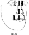
FIG. 3B is a schematic diagram of tagging some feature points in a first face image according to another embodiment of the present invention; -
FIG. 3C is a method flowchart of a process of establishing a correspondence between a first ratio and a preset face pitch angle according to an embodiment of the present invention; -
FIG. 3D is a method flowchart of a process of establishing a correspondence between a third ratio and a preset face pitch angle according to an embodiment of the present invention; -
FIG. 3E is a schematic diagram of some feature points in a frontal face image when a first face image is the frontal face image according to an embodiment of the present invention; -
FIG. 3F is a method flowchart of a process of establishing a correspondence between a second ratio and a preset face lateral rotation angle according to an embodiment of the present invention; -
FIG. 4A is a structural block diagram of an apparatus for determining a face rotation angle according to an embodiment of the present invention; -
FIG. 4B is a structural block diagram of an apparatus for obtaining first location information of a symmetrical midpoint of each pair of facial feature points according to another embodiment of the present invention; -
FIG. 4C is a structural block diagram of an apparatus for determining a face pitch angle in a to-be-determined face image according to another embodiment of the present invention; -
FIG. 4D is a structural block diagram of an apparatus for determining a face lateral rotation angle in a to-be-determined face image according to another embodiment of the present invention; -
FIG. 4E is a structural block diagram of an apparatus for calculating a fourth line segment according to another embodiment of the present invention; -
FIG. 4F is a structural block diagram of an apparatus for determining a face rotation angle according to another embodiment of the present invention; -
FIG. 4G is a structural block diagram of an apparatus for establishing a correspondence between a first ratio and a preset face pitch angle according to another embodiment of the present invention; -
FIG. 4H is a structural block diagram of an apparatus for establishing a correspondence between a third ratio and a preset face pitch angle according to still another embodiment of the present invention; -
FIG. 4I is a structural block diagram of an apparatus for establishing a correspondence between a second ratio and a preset face lateral rotation angle according to yet another embodiment of the present invention; and -
FIG. 5 is a structural block diagram of an electronic device according to some embodiments of the present invention. - To make the objectives, technical solutions, and advantages of the present disclosure clearer, the following further describes implementations of the present disclosure in detail with reference to the accompanying drawings. An "electronic device" mentioned in the text may include a smartphone, a tablet computer, an intelligent television, an e-book reader, an MP3 player (Moving Picture Experts Group Audio Layer III), an MP4 (Moving Picture Experts Group Audio Layer IV) player, a laptop portable computer, a desktop computer and the like.
-
FIG. 1 is a flowchart of a method for determining a face rotation angle according to an embodiment of the present invention. Referring toFIG. 1 , the method includes the following steps. - In step 101: Obtain first location information of preset multiple facial feature points in a to-be-determined face image, a quantity of the multiple facial feature points being an odd number, the multiple facial feature points including multiple pairs of symmetrical facial feature points and one first facial feature point, and the multiple facial feature points being not coplanar.
- In step 102: Obtain, according to first location information of facial feature points included in each pair of facial feature points of the multiple pairs of facial feature points, first location information of a symmetrical midpoint of each pair of facial feature points.
- In step 103: Determine a face rotation angle of the to-be-determined face image according to the first location information of the symmetrical midpoint of each pair of facial feature points and first location information of the first facial feature point.
- To sum up, according to the method for determining a face rotation angle provided in this embodiment, first, preset multiple pairs of symmetrical facial feature points and one first facial feature point are obtained; according to first location information of facial feature points included in each pair of facial feature points of the multiple pairs of facial feature points, first location information of a symmetrical midpoint of each pair of facial feature points is obtained; and a preset line segment ratio is calculated according to the first location information of the symmetrical midpoint of each pair of facial feature points and first location information of the first facial feature point, a correspondence between the preset line segment ratio and a face rotation angle is queried according to the line segment ratio, and the face rotation angle of the to-be-determined face image is determined, so as to resolve the problem that the face rotation angle cannot be determined. Because the correspondence between the preset line segment ratio and the face rotation angle is a relatively precise correspondence between a line segment ratio and an angle, the method for determining a face rotation angle provided in the embodiment of the present invention improves precision of determining a face rotation angle.
-
FIG. 2A is a flowchart of a method for determining a face rotation angle according to an embodiment of the present invention. In the method, preset multiple pairs of symmetrical facial feature points and one first facial feature point are obtained, and coordinate location information of the preset multiple pairs of symmetrical facial feature points and the first facial feature point in a to-be-determined face image is obtained; and a face rotation angle of the to-be-determined face image is determined according to the coordinate location information. Referring toFIG. 2A , the method includes the following steps. - In step 200: Detect preset multiple facial feature points in a to-be-determined face image.
- The preset multiple facial feature points are selected from points that are easily recognized in a face, and a preset facial feature point is located on a contour of a facial organ, and may be a turning point of the contour of the facial organ. For example, a preset feature point may be an inner eye corner, an outer eye corner, a mouth corner, the tail of a brow, the head of a brow, or a nasal tip, both the inner eye corner and the outer eye corner are turning points of a contour of an eye, the mouth corner is a turning point of a contour of a mouth, the tail of the brow and the head of the brow are turning points of a contour of an eyebrow, and the nasal tip is a turning point of a contour of a nose. Some feature points of the preset multiple feature points have a left-right symmetry. For example, two inner eye corners, two outer eye corners, two tails of brows, two heads of the brows, and two mouth corners in a face all have a left-right symmetry.
- A quantity of the preset multiple facial feature points is an odd number. For example, the quantity may be 5 or 7, the preset multiple facial feature points include multiple pairs of symmetrical facial feature points and one remaining first facial feature point, and the multiple facial feature points are not coplanar.
- In an implementation, in this embodiment, the multiple facial feature points may include five facial feature points, and the five facial feature points include a first pair of symmetrical facial feature points, a second pair of symmetrical facial feature points, and one remaining first facial feature point. In this embodiment, the first pair of symmetrical facial feature points may be two inner eye corners, the second pair of symmetrical facial feature points may be two mouth corners, and the remaining first facial feature point is a nasal tip.
- This step may be: first, a face in the to-be-determined face image is detected by using a face detection technology, and then the first pair of symmetrical facial feature points, that is, the two inner eye corners, the second pair of symmetrical facial feature points, that is, the two mouth corners, and the remaining first facial feature point, that is, the nasal tip are detected in the face by using a facial feature point detection technology.
- Certainly, after the preset facial feature points are detected completely, the detected facial feature points may be tagged. Referring to
FIG. 2B, FIG. 2B is a diagram of tagging feature points in a to-be-determined face image according to this embodiment (where the feature points in the figure not only include detected facial feature points, but also include a symmetrical midpoints formed by detected symmetrical facial feature points and another point, and are described in the following content). As shown inFIG. 2 , a detected preset first pair of symmetrical facial feature points, that is, two inner eye corners, are separately tagged as C' and D', a detected preset second pair of symmetrical facial feature points, that is, two mouth corners, are separately tagged as E' and F', and one detected preset remaining first facial feature point, that is, a nasal tip, is tagged as N'. - In step 201: Obtain first location information of preset multiple facial feature points in a to-be-determined face image.
- The first location information is a coordinate location of the facial feature point in a two-dimensional rectangular coordinate system or three-dimensional rectangular coordinate system when the to-be-determined face image is placed in the rectangular coordinate system. The two-dimensional rectangular coordinate system is a method for denoting a plane by using two coordinate axes that are separately an x axis and a y axis, where the x axis and the y axis are two axial directions perpendicular to each other. Therefore, a coordinate form of the first location information of the facial feature point obtained by using the two-dimensional rectangular coordinate system is (x, y). The three-dimensional rectangular coordinate system is a method for denoting a space by using three coordinate axes that are separately an x axis, a y axis, and a z axis, where the x axis, the y axis, and the z axis are three axial directions perpendicular to each other. Therefore, a coordinate form of the first location information of the facial feature point obtained by using the three-dimensional rectangular coordinate system is (x, y, z).
- After a facial feature point is detected, coordinates of the facial feature point are automatically obtained, where a coordinate form of the facial feature point is (x, y), and coordinates after positioning are output to a terminal. In this way, the terminal may directly obtain a coordinate location of the facial feature point after positioning. For example, coordinate locations obtained by the terminal of the preset first pair of symmetrical facial feature points (the two inner eye corners) are separately C' (x 1, y 1) and D' (x 2 , y 2), coordinate locations obtained by the terminal of the second pair of symmetrical facial feature points (the two mouth corners) are separately E' (x 3, y 3) and F' (x 4, y 4), and a coordinate location obtained by the terminal of the remaining first facial feature point (the nasal tip) is N' (x 5, y 5). For example, it is assumed that the obtained coordinate locations of the five facial feature points are separately: C' (0, 0), D' (2, 2), E' (1, -2), F' (2, -1), and N' (1.5, 0).
- In step 202: Obtain first location information of a first symmetrical midpoint of the first pair of symmetrical facial feature points according to first location information of each facial feature point included in the first pair of symmetrical facial feature points.
- Still using the foregoing example as an example, the first pair of symmetrical facial feature points are two inner eye corners. Coordinates of the two inner eye corners are separately C' (x 1 , y 1) and D' (x 2 , y 2), and a first symmetrical midpoint of the first pair of symmetrical facial feature points is a midpoint of a line segment C'D' formed by points C' (x 1 , y 1) and D' (x 2 , y 2). As shown in
FIG. 2B , the midpoint is tagged as A' (x 6, y 6), a coordinate location of A' (x 6, y 6) may be obtained by using a midpoint calculation formula. Specific calculation is shown in the following formulas (1) and (2):

- For example, when coordinate locations of C' (x 1 , y 1) and D' (x 2, y 2) are separately: C' (0, 0) and D' (2, 2), a coordinate location of a point A' (x 6, y 6) is calculated by using the following formulas (3) and (4):


- Therefore, the first location information of the first symmetrical midpoint of the first pair of symmetrical facial feature points is A' (1, 1).
- In step 203: Obtain first location information of a second symmetrical midpoint of the second pair of symmetrical facial feature points according to first location information of each facial feature point included in the second pair of symmetrical facial feature points.
- For example, the second pair of symmetrical facial feature points are two mouth corners. Coordinates of the two mouth corners are separately E' (x 3, y 3) and F' (x 4, y 4), and a second symmetrical midpoint of the second pair of symmetrical facial feature points is a midpoint of a line segment E'F' formed by points E' (x 3, y 3) and F' (x 4, y 4). As shown in
FIG. 2B , the midpoint is tagged as B', a coordinate location of B' (x 7, y 7) is obtained by using a midpoint calculation formula. Specific calculation is shown in the following formulas (5) and (6):

- For example, when specific coordinates of the points E' (x 3, y 3) and F' (x 4, y 4) are E' (1, -2) and F' (2, -1), coordinates of the second symmetrical midpoint are calculated by using the following formulas (7) and (8):


- Therefore, the first location information of the second symmetrical midpoint of the second pair of symmetrical facial feature points is B' (1.5, -1.5).
- In step 204: Determine a face pitch angle of the to-be-determined face image according to the first location information of the symmetrical midpoint of each pair of facial feature points and first location information of the first facial feature point.
- The face rotation angle of the to-be-determined face image may be the face pitch angle or a face lateral rotation angle. A method for determining a face pitch angle and a method for determining a face lateral rotation angle are separately described below.
- The face pitch angle of the to-be-determined face image is determined according to the first location information of the symmetrical midpoint of each pair of facial feature points and first location information of the first facial feature point. Referring to
FIG. 2C , the method may include the following steps. - In
step 204a: Calculate a length of a first line segment formed by the first symmetrical midpoint and the first facial feature point according to the first location information of the first symmetrical midpoint and the first location information of the first facial feature point. - It can be learned from
step 202 that, the first symmetrical midpoint of the first pair of symmetrical facial feature points is A' (x 6, y 6), and the first location information of the first facial feature point is N' (x 5, y 5), and a length of a first line segment A'N' formed by the first symmetrical midpoint A' (x 6, y 6) and the first facial feature point N' (x 5, y 5) is calculated by using a formula for a distance between two points. Specific calculation is shown in the following formula (9):
- In
step 204b: Calculate a length of a second line segment formed by the second symmetrical midpoint and the first facial feature point according to the first location information of the second symmetrical midpoint and the first location information of the first facial feature point. - It can be learned from
step 203 that, the first symmetrical midpoint of the first pair of symmetrical facial feature points is B' (x 7 , y 7), and the first location information of the first facial feature point is N' (x 5, y 5), and a length of a first line segment B'N' formed by the first symmetrical midpoint B' (x 7 , y 7) and the first facial feature point N' (x 5, y 5) is calculated by using a formula for a distance between two points. Specific calculation is shown in the following formula (10):
- In
step 204c: Obtain, according to a first ratio of the length of the first line segment to the length of the second line segment and from a correspondence between the first ratio and a face pitch angle, the face pitch angle of the to-be-determined face image. - The first ratio of the length A'N' of the first line segment to the length B'N' of the second line segment is calculated, a pre-established correspondence between the first ratio and the face pitch angle is queried according to the first ratio (for a process of establishing the correspondence, refer to the following
steps 302a to 302e), and the face pitch angle corresponding to the calculated first ratio is queried from the correspondence, and the face pitch angle is determined as the face pitch angle of the to-be-determined face image. - It should be noted that if the first ratio calculated in this step is not found in all first ratios included in the pre-established correspondence between the first ratio and the face pitch angle, a first ratio closest to the first ratio calculated in this step is determined from all the first ratios in the correspondence, and then a face pitch angle corresponding to the closest first ratio is used as the face pitch angle corresponding to the first ratio calculated in this step.
- Additionally, the first ratio closest to the first ratio calculated in this step may be determined from all the first ratios in the correspondence by using the following method:
- Subtraction is performed on each first ratio included in the pre-established correspondence between the first ratio and the face pitch angle and the first ratio calculated in this step, to obtain a first ratio difference, then an absolute value operation is performed on each first ratio difference, values obtained after the absolute value operation are compared, to obtain a minimum absolute value, then a first ratio corresponding to the minimum absolute value (a a first ratio included in the correspondence between the first ratio and the face pitch angle) is obtained, and the first ratio is determined as the first ratio closest to the first ratio calculated in this step.
- In step 205: Determine a face lateral rotation angle of the to-be-determined face image according to the first location information of the symmetrical midpoint of each pair of facial feature points and first location information of the first facial feature point.
- The face lateral rotation angle of the to-be-determined face image is determined according to the first location information of the symmetrical midpoint of each pair of facial feature points, the first location information of the first facial feature point, and the face pitch angle that is determined by using the foregoing process. Referring to
FIG. 2D , the method may include the following steps. - In
step 205a: Calculate a first vertical distance from the first facial feature point to a third line segment and a length of the third line segment according to the first location information of the first symmetrical midpoint, the first location information of the second symmetrical midpoint, and the first location information of the first facial feature point. - It can be learned from
step 202 that, the first location information of the first symmetrical midpoint is A' (x 6, y 6). It can be learned fromstep 203 that, the first location information of the second symmetrical midpoint is B' (x 7, y 7). It can be learned fromstep 201 that, the first location information of the first facial feature point is N' (x 5, y 5). The third line segment is a line segment A'B' formed by the first symmetrical midpoint A' (x 6, y 6) and the second symmetrical midpoint B' (x 7 , y 7), and the first vertical distance from the first facial feature point to the third line segment is calculated by using the following method: first, a straight line passing through the point A' and the point B' is tagged as a straight line c, a general straight-line equation of the straight line c is calculated according to the first location information of the point A' and the point B', and then a first vertical distance from the first facial feature point N' to the straight line c is calculated according to the first location information of the first facial feature point N'. Details are as follows: - First, an equation of a two-point-form straight line passing through the point A' (x 6, y 6) and the point B' (x 7 , y 7) is obtained according to a two-point-form straight line formula, and the equation of a two-point-form straight line is shown in the following formula (11):

- The foregoing equation is equivalently transformed, and transformed into a general straight-line equation, and the general straight-line equation is shown in the following formula (12):

- Certainly, the straight line c passing through the point A' (x 6, y 6) and the point B' (x 7 , y 7) may be further calculated by using another method, and details are not described herein.
- Then, a distance d from the first facial feature point N' (x 5, y 5) to the straight line c is calculated according to a point-to-line distance formula, and specific calculation is shown in the following formula (13):

- Because the straight line c is a straight line passing through the point A' (x 6, y 6) and the point B' (x 7 , y7 ), the distance d from the first facial feature point N' (x 5 , y 5) to the straight line c is a second vertical distance from the first facial feature point N' (x 5, y 5) to the third line segment A'B'. Therefore, the first vertical distance is the distance d.
- The length of the third line segment is obtained by using a formula for a distance between two points, and specific calculation is shown in the following formula (14):

- In
step 205b: Obtain, according to the face pitch angle and from a correspondence between the face pitch angle and a third ratio, the corresponding third ratio. - A pre-established correspondence between a third ratio and a face pitch angle is queried according to the face pitch angle determined in step 204 (for a process of establishing the correspondence, refer to
subsequent steps 303a to 303f), a third ratio corresponding to a face pitch angle is queried from the correspondence, the face pitch angle is the face pitch angle determined instep 204, and the third ratio is tagged as e. - It should be noted that if the face pitch angle determined in
step 204 is not found in all face pitch angles included in the pre-established correspondence between a third ratio and a face pitch angle, a face pitch angle closest to the face pitch angle calculated instep 204 is determined from all the face pitch angles, and then a third ratio corresponding to the closest face pitch angle is used as the third ratio corresponding to the face pitch angle. - Additionally, the face pitch angle closest to the face pitch angle calculated in
step 204 may be determined from all the face pitch angles by using the following method. - Subtraction is performed on each face pitch angle included in the pre-established correspondence between the third ratio and the face pitch angle and the face pitch angle determined in
step 204, to obtain a face pitch angle difference, then an absolute value operation is performed on each face pitch angle difference, values obtained after the absolute value operation are compared, to obtain a minimum absolute value, then a face pitch angle corresponding to the minimum absolute value (a face pitch angle included in the correspondence between the third ratio and the face pitch angle) is obtained, and the face pitch angle is determined as the face pitch angle closest to the face pitch angle calculated instep 204. - It can be learned from
step 303d,step 303e, and step 303f that, the third ratio is a ratio of the following two values: a first value that is a line segment formed by the symmetrical midpoint of the first pair of facial feature points and the symmetrical midpoint of the second pair of facial feature points in the to-be-determined face image, that is, the third line segment A'B', and a second value that is a fourth line segment AB formed by a third symmetrical midpoint A of the first pair of facial feature points in a frontal face image and a fourth symmetrical midpoint B of the second pair of facial feature points in the frontal face image. Therefore, a value of e is a ratio of the third line segment to the fourth line segment, and therefore the value of e is calculated by using the following formula (15):
- In
step 205c: Calculate the length of the fourth line segment according to the third ratio and the length of the third line segment. - It can be learned from
step 205b that, the third ratio is the ratio of the third line segment to the fourth line segment. Therefore, the length of the fourth line segment is a ratio of the third line segment to the third ratio. Therefore, the value of the fourth line segment may be calculated by using the following formula (16):
- In
step 205d: Obtain, according to a second ratio of the first vertical distance to the length of the fourth line segment and from a correspondence between the second ratio and a face lateral rotation angle, the face lateral rotation angle of the to-be-determined face image. - This step may be: The second ratio of the first vertical distance d to the length the fourth line segment AB is calculated, a pre-established correspondence between the second ratio and the face lateral rotation angle is queried according to the second ratio (for a process of establishing the correspondence, refer to
subsequent steps 304a to 304b), and a face lateral rotation angle corresponding to a second ratio same as the calculated second ratio is queried from the correspondence, and the face lateral rotation angle is determined as the face lateral rotation angle of the to-be-determined face image. - It should be noted that if the second ratio calculated in this step is not found in all second ratios included in the pre-established correspondence between the second ratio and the face lateral rotation angle, a second ratio closest to the second ratio calculated in this step is determined from all the second ratios in the correspondence, and then a face lateral rotation angle corresponding to the closest second ratio is used as the face lateral rotation angle corresponding to the second ratio calculated in this step.
- Additionally, the second ratio closest to the second ratio calculated in this step may be determined from all the second ratios in the correspondence by using the following method:
- Subtraction is performed on each second ratio included in the pre-established correspondence between the second ratio and the face lateral rotation angle and the second ratio calculated in this step, to obtain a second ratio difference, then an absolute value operation is performed on each second ratio difference, values obtained after the absolute value operation are compared, to obtain a minimum absolute value, then a second ratio corresponding to the minimum absolute value (a a second ratio included in the correspondence between the second ratio and the face lateral rotation angle) is obtained, and the second ratio is determined as the second ratio closest to the second ratio calculated in this step.
- In step 206: Determine a fifth line segment according to first location information of each facial feature point in any pair of symmetrical facial feature points, and calculate an angle between the fifth line segment and a horizontal line, to obtain the face rotation angle of the to-be-determined face image.
- The fifth line segment is a line segment formed by two facial feature points in any pair of symmetrical facial feature points in the preset facial feature points. Therefore, two points forming the fifth line segment in this embodiment may be the first pair of symmetrical facial feature points, that is, the two inner eye corners, or a second pair of symmetrical facial feature points, that is, the two mouth corners.
- The face rotation angle is an angle obtained by rotating the face horizontally when a frontal direction of the face is always forward.
- For example, the any pair of symmetrical facial feature points are two inner eye corners C' (x 1 , y1) and D' (x 2 , y 2), and the fifth line segment is a line segment C'D' determined according to points C' (x 1 , y 1) and D' (x2, y 2). Certainly, the fifth line segment may be two mouth corners E' (x 3, y 3) and F' (x 4, y 4), and the fifth line segment is a line segment E'F' determined according to points E' (x 3, y 3) and F' (x 4, y 4).
- For example, if the fifth line segment is C'D', a specific process of calculating an angle (denoted by using □α) between the fifth line segment and the horizontal line is as follows:
- First, a cosine value of □α is calculated. Referring to
FIG. 2D , a specific method for calculating the cosine value of □α is shown in the following formula (17):
- Therefore, the value of □α may be obtained by taking inverse cosine of the foregoing cosine value of □α, and a specific calculation method is shown in the following formula (18):

- □α is the face rotation angle of the to-be-determined face image.
- For example, when coordinate locations of C' (x 1 , y 1) and D' (x 2, y 2) are separately: C' (0, 0) and D' (2, 2), a process of calculating □α is shown in the following formula (19):

- Therefore, □α is 45°.
- It should be noted that when the face rotation angle of the to-be-determined face image is determined, the face rotation angle may be determined only according to the first location information of each facial feature point in any pair of symmetrical facial feature points. Therefore, in an actual operation, if only a face rotation angle of a face image needs to be determined,
step 206 may be directly performed afterstep 201 is performed completely. - To sum up, according to the method for determining a face rotation angle provided in this embodiment of the present invention, first, preset multiple pairs of symmetrical facial feature points and one first facial feature point are obtained; according to first location information of facial feature points included in each pair of facial feature points of the multiple pairs of facial feature points, first location information of a symmetrical midpoint of each pair of facial feature points is obtained; and a preset line segment ratio is calculated according to the first location information of the symmetrical midpoint of each pair of facial feature points and first location information of the first facial feature point, a correspondence between the preset line segment ratio and a face rotation angle is queried according to the line segment ratio, and the face rotation angle of the to-be-determined face image is determined, so as to resolve the problem that the face rotation angle cannot be determined. Because the correspondence between the preset line segment ratio and the face rotation angle is a relatively precise correspondence between a line segment ratio and an angle (as for a reason why the correspondence is a relatively precise correspondence is discussed in the following content), the method for determining a face rotation angle provided in the embodiment of the present invention improves precision of determining a face rotation angle.
- When either of a face pitch angle and a face lateral rotation angle of the to-be-determined face image is determined, a correspondence between a line segment ratio and a preset face rotation angle needs to be queried. The correspondence is already established before a rotation angle of the to-be-determined face image is determined, so that the correspondence may be directly queried when the rotation angle of the to-be-determined face image is determined. A line segment is a line segment formed by connecting midpoints of two facial feature points of preset multiple facial feature points, a vertical line segment formed by a vertical distance from a facial feature point to another straight line, or the like.
- In this embodiment, three correspondences between line segment ratios and preset face rotation angles are established. A first correspondence is a correspondence between a first ratio and a preset face pitch angle, a second correspondence is a correspondence between a third ratio and a preset face pitch angle, and a third correspondence is a correspondence between a second ratio and a preset face lateral rotation angle. Referring to
FIG. 3A , an establishment process is as follows: - In step 301: Obtain second location information of the preset multiple facial feature points in a first face image.
- The meaning of the preset multiple facial feature points is the same as that of the foregoing preset multiple facial feature points, and details are not described herein.
- The first face image is a face image that is shot after a face rotates by a preset face rotation angle. The preset face rotation angle includes a preset face pitch angle and a preset face lateral rotation angle, the preset face pitch angle and the preset face lateral rotation angle may be a series of preset discrete rotation angles, and a difference between each two neighboring rotation angles of this series of discrete rotation angles is the same. The difference is relatively small, and may be set to 1°, 2°, or another relatively small value, so as to ensure that a comprehensive correspondence between a line segment ratio and the preset face rotation angle is established in the following process, so that when the correspondence is queried, an accurate line segment ratio and an accurate face rotation angle may be obtained.
- The second location information is obtained by placing the face in a three-dimensional rectangular coordinate system (three coordinate axes are used and are separately an x axis, a y axis, and a z axis, and the x axis, the y axis, and the z axis are three axial directions perpendicular to each other, and are a method for denoting a space). The three-dimensional rectangular coordinate system may be any three-dimensional rectangular coordinate system. Therefore, a coordinate form of the second location information of the facial feature point obtained by using the three-dimensional rectangular coordinate system is (x, y, z).
- Therefore, the foregoing preset face rotation angle may be described in the following manner: a face pitch angle is a face rotation angle obtained when a frontal face rotates along the y axis, but does not rotate on the x axis or the z axis; and a face lateral rotation angle is a face rotation angle obtained when the frontal face rotates along the z axis, but does not rotate on the x axis or the y axis.
- In an implementation, the preset face rotation angle may be obtained by using the following method: an initial face rotation angle is set to 0°, that is, the front of the face is forward and has not any rotation angle, and a difference between two neighboring rotation angles is preset; therefore, a first preset face rotation angle is the difference between the two neighboring rotation angles, a second preset rotation angle is the first preset face rotation angle plus the difference between the two neighboring rotation angles, and a third preset rotation angle is the second preset face rotation angle plus the difference between the two neighboring rotation angles; and all preset face rotation angles are obtained sequentially according to this method, and a quantity of the preset face rotation angles is a ratio of 360° to the preset difference between the two neighboring rotation angles.
- Using a preset face pitch angle as an example, first, a face is set to a frontal face, and a difference between two neighboring face pitch angles is preset to 1°; therefore, a first preset face rotation angle is a difference 1° between the two neighboring rotation angles, a second preset rotation angle is the first preset face rotation angle plus the difference between the two neighboring rotation angles, that is, 1°+1°=2°, and a third preset rotation angle is the second preset face rotation angle plus the difference between the two neighboring rotation angles, that is, 2°+1°=3°; preset face pitch angles are obtained sequentially according to this method, and a quantity of the preset face rotation angles is a ratio of 360° to the preset difference 1° between the two neighboring rotation angles, that is, 360.
- In an implementation, the second location information of the preset multiple facial feature points in the first face image may be obtained by using the following method: first, a face is placed as a frontal face, and the frontal face is rotated according to a preset angle difference between each two neighboring face rotation angles; after the frontal face is rotated by the preset angle difference each time, a face image is shot, and coordinate locations of preset multiple facial feature points of the shot face image are obtained, and are tagged as second location information. For example, if a difference between each two neighboring face rotation angles is 1°, the frontal face is first rotated by 1°, the face is shot in this case, to obtain a face image, and coordinate locations of preset multiple facial feature points of the face image are obtained; and then the face continues to be rotated by 1°, the face is shot again to obtain a face image, and coordinate locations of preset multiple facial feature points in the face image in this case are obtained; the foregoing steps are repeated, until the face is rotated by all preset angles and a coordinate locations of the facial feature points at each preset angle are obtained.
- Referring to
FIG. 3B, FIG. 3B includes multiple facial feature points in a first face image shown in this embodiment. As shown inFIG. 3B , two inner eye corners in a preset first pair of symmetrical facial feature points are separately tagged as G' and H', two mouth corners of a second pair of symmetrical facial feature points are separately tagged as I' and J', and one remaining first facial feature point is a nasal tip and tagged as O'. Coordinates of second locations of the preset multiple facial feature points in the first face image are separately: G' (x 9, y 9, z 9), H' (x 10, y10, z 10), I' (x 11, y 11, z 11), J'(x 12, y 12, z 12), and O'(x 13, y 13, z 13). - In step 302: Establish a correspondence between a first ratio and the preset face pitch angle according to the second location information of the preset multiple facial feature points.
- The first correspondence is the correspondence between the first ratio and the preset face pitch angle. Referring to
FIG. 3C, FIG. 3C is a method flowchart of a process of establishing a correspondence between a first ratio and a preset face pitch angle, and the method includes the following steps. - In
step 302a: Obtain second location information of a fifth symmetrical midpoint of the first pair of symmetrical facial feature points according to second location information of each facial feature point included in the first pair of symmetrical facial feature points. - Still using the foregoing example as an example, the first pair of symmetrical facial feature points are two inner eye corners G' (x 9, y 9, z 9) and H' (x 10, y 10, z 10). Still referring to
FIG. 3B , a fifth symmetrical midpoint of the first pair of symmetrical facial feature points is a midpoint of a line segment G'H' formed by the point G' (x 9, y 9, z 9) and the point H' (x 10, y 10, z 10), the midpoint of the line segment G'H' is tagged as K', a coordinate location of K' (x 14, y 14, z 14) is obtained by using a midpoint calculation formula, and a specific calculation process is shown in the following formulas (20), (21) and (22):


- In
step 302b: Obtain second location information of a sixth symmetrical midpoint of the second pair of symmetrical facial feature points according to first location information of each facial feature point included in the second pair of symmetrical facial feature points. - Still using the foregoing example as an example, the second pair of symmetrical facial feature points are two mouth corners I' (x 11, y 11, z 11) and J' (x 12, y 12, z 12). Still referring to
FIG. 3B , a sixth symmetrical midpoint of the second pair of symmetrical facial feature points is a midpoint of a line segment formed by points I'(x 11, y 11, z 11) and J' (x 12, y 12, z 12), the midpoint is tagged as L', a coordinate location of L' (x 15, y 15, z 15) is obtained by using a midpoint calculation formula, and a specific calculation process is shown in the following formulas (23), (24) and (25):


- In
step 302c: Calculate a length of a sixth line segment formed by the fifth symmetrical midpoint and the first facial feature point according to the second location information of the fifth symmetrical midpoint and the second location information of the first facial feature point. - Still using the foregoing example as an example, the second location information of the fifth symmetrical midpoint is K' (x 14, y 14, z 14), the first facial feature point is a nasal tip O' (x 13, y 13, z 13), the sixth line segment formed by the fifth symmetrical midpoint and the first facial feature point is a length of a line segment K'O' formed by K' (x 14, y 14, z 14) and the point O' (x 13, y 13, z 13), the length of the sixth line segment is calculated by using a formula for a distance between two points, and specific calculation is shown in the following formula (26):

- In
step 302d: Calculate a length of a seventh line segment formed by the sixth symmetrical midpoint and the first facial feature point according to the second location information of the sixth symmetrical midpoint and the second location information of the first facial feature point. - Still using the foregoing example as an example, the second location information of the sixth symmetrical midpoint is L' (x 15, y 15, z 15), the first facial feature point is a nasal tip O' (x 13, y 13, z 13), the seventh line segment formed by the sixth symmetrical midpoint and the first facial feature point is a length of a line segment L'O' formed by L' (x 15, y 15, z 15) and the point O' (x 13, y 13, z 13), the length of the seventh line segment is calculated by using a formula for a distance between two points, and specific calculation is shown in the following formula (27):

- In
step 302e: Establish a correspondence between a first ratio of the sixth line segment to the seventh line segment and the preset face pitch angle. - Still using the foregoing example as an example, the sixth line segment is K'O', and the seventh line segment is L'O', and therefore the first ratio is a ratio of K'O' to L'O'. A correspondence between the first ratio and the preset face pitch angle is obtained by using the following method: a face is rotated; when a face rotation angle is a preset first face pitch angle, the face is stopped from being rotating; in a case of the first face pitch angle, a ratio of K'O' to L'O' is calculated, to obtain a first first ratio, and a correspondence between the first first ratio and the preset first face pitch angle is stored; and the face continues to be rotated; when the face rotation angle is a preset second face pitch angle, in a case of the second face pitch angle, a ratio of K'O' to L'O' is calculated, to obtain a second first ratio, and a correspondence between the second first ratio and the preset second face pitch angle is stored; and the foregoing steps are repeated, until correspondences between all first ratios and preset face pitch angles are stored completely.
- In step 303: Establish a correspondence between a third ratio and the preset face pitch angle according to the second location information of the preset multiple facial feature points.
- The second correspondence is the correspondence between the third ratio and the preset face pitch angle. Referring to
FIG. 3D, FIG. 3D is a method flowchart of a process of establishing a correspondence between a third ratio and a preset face pitch angle, and the method includes the following steps. - In
step 303a: Obtain third location information of each facial feature point included in the first pair of symmetrical facial feature points in the frontal face image of the face, and third location information of each facial feature point included in the second pair of symmetrical facial feature points in the frontal face image. - Refer to
FIG. 3E, FIG. 3E includes multiple facial feature points in a frontal face image when a first face image shown this embodiment is the frontal face image. As shown inFIG. 3E , the first pair of symmetrical facial feature points are two inner eye corners and are separately tagged as G and H, and third location information of G and third location information of H in the frontal face image of the face are respectively G (x 16, y 16, z 16) and H (x 17, y 17, z17 ). The second pair of symmetrical facial feature points are two mouth corners and are separately tagged as I' and J', and third location information of I' and third location information of J' in the frontal face image are respectively I' (x 18, y 18, z 18) and J' (x 19, y 19, z 19). - In
step 303b: Obtain third location information of a seventh symmetrical midpoint of the first pair of symmetrical facial feature points according to the third location information of each facial feature point included in the first pair of symmetrical facial feature points. - Still using the foregoing example as an example, still referring to
FIG. 3E , the first pair of symmetrical facial feature points are two inner eye corners G (x 16, y 16, z 16) and H (x 17, y 17, z 17), a seventh symmetrical midpoint of the first pair of symmetrical facial feature points is a midpoint of a line segment formed by the points G (x 16, y 16, z 16) and H (x 17 , y 17, z 17), the midpoint is tagged as K, a coordinate location of K (x 18, y 18, z 18) is obtained by using a midpoint calculation formula, and specific calculation is shown in the following formulas (28), (19) and (30):


- In
step 303c: Obtain third location information of an eighth symmetrical midpoint of the second pair of symmetrical facial feature points according to the third location information of each facial feature point included in the second pair of symmetrical facial feature points. - Still using the foregoing example as an example, still referring to
FIG. 3E , the second pair of symmetrical facial feature points are two mouth corners I (x 20, y 20, z 20) and J (x 21, y 21, Z 21), an eighth symmetrical midpoint of the second pair of symmetrical facial feature points is a midpoint of a line segment IJ formed by the points I (x 20, y 20, z 20) and J (x 21, y 21, z 21), the midpoint is tagged as L, a coordinate location of L (x 22, y 22, z 22) is obtained by using a midpoint calculation formula, and specific calculation is shown in the following formulas (31), (32) and (33):


- In
step 303d: Calculate a length of an eighth line segment formed by the fifth symmetrical midpoint and the sixth symmetrical midpoint according to the second location information of the fifth symmetrical midpoint and the second location information of the sixth symmetrical midpoint. - The second location information of the fifth symmetrical midpoint is K' (x 14, y 14, z 14), the second location information of the sixth symmetrical midpoint is L' (x 15, y 15, z 15), the length of the eighth line segment K'L' formed by the fifth symmetrical midpoint K' (x 14, y 14, z 14) and the sixth symmetrical midpoint L' (x 15, y 15, z 15) is a distance from the point K' (x 14, y 14, z 14) to the point L' (x 15, y 15, z 15), and is calculated by using a formula for a distance between two points, and specific calculation is shown in the following formula (34):

- In
step 303e: Calculate a length of a ninth line segment formed by the seventh symmetrical midpoint and the eighth symmetrical midpoint according to the third location information of the seventh symmetrical midpoint and the third location information of the eighth symmetrical midpoint. - The third location information of the seventh symmetrical midpoint is K (x 18, y 18, z 18) and the third location information of the eighth symmetrical midpoint is L (x 22, y 22, z 22), the length of the ninth line segment KL formed by the seventh symmetrical midpoint K (x 18, y 18, z 18) and the eighth symmetrical midpoint L (x 22, y 22, z 22) is a distance from the point K (x 18, y 18, z 18) to the point L (x 22, y 22, z 22), and is calculated by using a formula for a distance between two points, and specific calculation is shown in the following formula (35):

- In
step 303f: Establish a correspondence between a third ratio of the eighth line segment to the ninth line segment and the preset face pitch angle. - Still using the foregoing example as an example, the eighth line segment is K'L', and the ninth line segment is KL, and therefore the third ratio is a ratio of K'L' to KL. A correspondence between the third ratio and the preset face pitch angle is obtained by using the following method: a face is rotated; when a face rotation angle is a preset first face pitch angle, the face is stopped from being rotating; in a case of the first face pitch angle, a ratio of K'L' to KL is calculated, to obtain a first third ratio, and a correspondence between the first third ratio and the preset first face pitch angle is stored; and the face continues to be rotated; when the face rotation angle is a preset second face pitch angle, in a case of the second face pitch angle, a ratio of K'L' to KL is calculated, to obtain a second third ratio, and a correspondence between the second third ratio and the preset second face pitch angle is stored; and the foregoing steps are repeated, until correspondences between all third ratios and preset face pitch angles are stored completely.
- In step 304: Establish a correspondence between a second ratio and the preset face lateral rotation angle according to the second location information of the preset multiple facial feature points.
- The third correspondence is the correspondence between the second ratio and the preset face lateral rotation angle. Referring to
FIG. 3F, FIG. 3F is a method flowchart of a process of establishing a correspondence between a second ratio and a preset face lateral rotation angle, and the method includes the following steps. - In
step 304a: Calculate a second vertical distance from the first facial feature point to the eighth line segment according to the second location information of the fifth symmetrical midpoint, the second location information of the sixth symmetrical midpoint, and the second location information of the first facial feature point. - It can be learned from
step 302a that, the second location information of the fifth symmetrical midpoint is K' (x 14, y 14, z 14). It can be learned fromstep 302b that, the second location information of the sixth symmetrical midpoint is L' (x 15, y 15, z 15). It can be learned fromstep 205 that, the second location information of the first facial feature point is O' (x 13, y 13, z 13), and the second vertical distance from the first facial feature point O' (x 13, y 13, z 13) to the eighth line segment K'L' is calculated by using the following process: - First, according to the second location information K' (x 14, y 14, z 14) of the fifth symmetrical midpoint and the second location information L' (x 15, y 15, z 15) of the sixth symmetrical midpoint, a straight line a passing through the point K' (x 14, y 14, z 14) and the point L' (x 15, y 15, z 15) is calculated, and specific calculation is as follows:
- First, an equation of a two-point-form straight line passing through the point K' (x 14, y 14, z 14) and the point L' (x 15, y 15, z 15) is obtained according to a two-point-form straight line formula, and is shown in the following formula (36):

- The foregoing equation is equivalently transformed, and transformed into a general straight-line equation that is shown in the following formula (37):

- Certainly, the straight line a passing through the point K' (x 14, y 14, z 14) and the point L' (x 15, y 15, z 15) may be further calculated by using another method, and details are not described herein.
- Then, a distance b from the first facial feature point O' (x 13, y 13, z 13) to the straight line a is calculated according to a point-to-line distance formula, and specific calculation is shown in the following formula (38):

- Because the straight line a is a straight line passing through the K' (x 14, y 14, z 14) and the point L' (x 15, y 15, z 15), the distance b from the first facial feature point O' (x 13, y 13, z 13) to the straight line a is a second vertical distance from the first facial feature point O' (x 13, y 13, z 13) to the eighth line segment K'L'. Therefore, the second vertical distance is the distance b.
- In
step 304b: Establish a correspondence between a second ratio of the second vertical distance to the ninth line segment and the preset face lateral rotation angle. - Still using the foregoing example as an example, the second vertical distance is b, and the ninth line segment is KL, and therefore the second ratio is a ratio of b to KL. A correspondence between the second ratio and the preset face lateral rotation angle is obtained by using the following method: a face is rotated; when a face rotation angle is a preset first face lateral rotation angle, the face is stopped from being rotating; in a case of the first face lateral rotation angle, a ratio of b to KL is calculated, to obtain a first second ratio, and a correspondence between the first second ratio and the preset first face lateral rotation angle is stored; and the face continues to be rotated; when the face rotation angle is a preset second face lateral rotation angle, in a case of the second face lateral rotation angle, a ratio of b to KL is calculated, to obtain a second second ratio, and a correspondence between the second second ratio and the preset second face lateral rotation angle is stored; and the foregoing steps are repeated, until correspondences between all second ratios and preset face lateral rotation angles are stored completely.
- To sum up, according to the method for establishing a correspondence between a line segment ratio and a preset face rotation angle provided in this embodiment of the present invention, in a three-dimensional rectangular coordinate system, a 3D model of a frontal face is rotated according to a preset angle, coordinate information of a facial feature point is obtained each time the 3D model is rotated by a preset angle, and a correspondence between a line segment ratio and a preset face rotation angle is established according to the obtained coordinate information. Because the preset angle is relatively small, the line segment ratio or the face rotation angle in the correspondence is relatively precise. Moreover, because the correspondence is pre-established, the line segment ratio or the face rotation angle may be directly obtained from the correspondence in a process of determining the face rotation angle, thereby reducing a time needed for determining the face rotation angle, and improving efficiency of determining the face rotation angle.
- Apparatus embodiments of the present invention are described below, and may be used to perform the method embodiments of the present invention. For details not disclosed in the apparatus embodiments of the present invention, refer to the method embodiments of the present invention.
- Referring to
FIG. 4A, FIG. 4A is a structure block diagram of an apparatus for determining a face rotation angle according to an embodiment of the present invention. As shown inFIG. 4A , the apparatus for determining a face rotation angle includes but is not limited to including: a first obtainingmodule 401, a second obtainingmodule 402, and a first determiningmodule 403. - The first obtaining
module 401 is configured to obtain first location information of preset multiple facial feature points in a to-be-determined face image, a quantity of the multiple facial feature points being an odd number, the multiple facial feature points including multiple pairs of symmetrical facial feature points and one first facial feature point, and the multiple facial feature points being not coplanar. - The second obtaining
module 402 is configured to obtain, according to first location information that is of facial feature points included in each pair of facial feature points of the multiple pairs of facial feature points and that is obtained by the first obtainingmodule 401, first location information of a symmetrical midpoint of each pair of facial feature points. - The first determining
module 403 is configured to determine a face rotation angle of the to-be-determined face image according to the first location information that is of the symmetrical midpoint of each pair of facial feature points and that is obtained by the second obtainingmodule 402 and first location information that is of the first facial feature point and that is obtained by the first obtainingmodule 401. - To sum up, according to the apparatus for determining a face rotation angle provided in this embodiment, first, preset multiple pairs of symmetrical facial feature points and one first facial feature point are obtained; according to first location information of facial feature points included in each pair of facial feature points of the multiple pairs of facial feature points, first location information of a symmetrical midpoint of each pair of facial feature points is obtained; and a preset line segment ratio is calculated according to the first location information of the symmetrical midpoint of each pair of facial feature points and first location information of the first facial feature point, a correspondence between the preset line segment ratio and a face rotation angle is queried according to the line segment ratio, and the face rotation angle of the to-be-determined face image is determined, so as to resolve the problem that the face rotation angle cannot be determined. Because the correspondence between the preset line segment ratio and the face rotation angle is a relatively precise correspondence between a line segment ratio and an angle, the method for determining a face rotation angle provided in the embodiment of the present invention improves precision of determining a face rotation angle.
- In an implementation, the multiple facial feature points include five facial feature points, and the five facial feature points include a first pair of symmetrical facial feature points, a second pair of symmetrical facial feature points, and one remaining first facial feature point.
- Referring to
FIG. 4B, FIG. 4B is a structure block diagram of a second obtainingmodule 402 according to an embodiment of the present invention. As shown inFIG. 4B , the second obtainingmodule 402 includes but is not limited to including: a first obtaining sub-module 4021, and a second obtaining sub-module 4022. - The first obtaining sub-module 4021 is configured to obtain first location information of a first symmetrical midpoint of the first pair of symmetrical facial feature points according to first location information that is of each facial feature point included in the first pair of symmetrical facial feature points and that is obtained by the first obtaining
module 401. - The second obtaining sub-module 4022 is configured to obtain first location information of a second symmetrical midpoint of the second pair of symmetrical facial feature points according to first location information that is of each facial feature point included in the second pair of symmetrical facial feature points and that is obtained by the first obtaining
module 401. - Referring to
FIG. 4C, FIG. 4C is a structure block diagram of a first determiningmodule 403 according to an embodiment of the present invention. As shown inFIG. 4C , the first determiningmodule 403 includes but is not limited to including: afirst calculation sub-module 4031, asecond calculation sub-module 4032, and a third obtaining sub-module 4033. - The
first calculation sub-module 4031 is configured to calculate a length of a first line segment formed by the first symmetrical midpoint and the first facial feature point according to the first location information that is of the first symmetrical midpoint and that is obtained by the first obtaining sub-module 4021 and the first location information that is of the first facial feature point and that is obtained by the first obtainingmodule 401. - The
second calculation sub-module 4032 is configured to calculate a length of a second line segment formed by the second symmetrical midpoint and the first facial feature point according to the first location information that is of the second symmetrical midpoint and that is obtained by the second obtaining sub-module 4022 and the first location information that is of the first facial feature point and that is obtained by the first obtainingmodule 401. - The third obtaining sub-module 4033 is configured to obtain, according to a first ratio of the length of the first line segment calculated by the
first calculation sub-module 4031 to the length of the second line segment calculated by thesecond calculation sub-module 4032 and from a correspondence between the first ratio and a face pitch angle, the face pitch angle of the to-be-determined face image. - Referring to
FIG. 4D, FIG. 4D is a structure block diagram of a first determiningmodule 403 according to another embodiment of the present invention. As shown inFIG. 4D , the first determiningmodule 403 includes but is not limited to including: athird calculation sub-module 4034, afourth calculation sub-module 4035, and a fourth obtaining sub-module 4036. - The
third calculation sub-module 4034 is configured to calculate a first vertical distance from the first facial feature point to a third line segment and a length of the third line segment according to the first location information that is of the first symmetrical midpoint and that is obtained by the first obtaining sub-module 4021, the first location information that is of the second symmetrical midpoint and that is obtained by the second obtaining sub-module 4022, and the first location information that is of the first facial feature point and that is obtained by the first obtainingmodule 401, where the third line segment is a line segment formed by the first symmetrical midpoint and the second symmetrical midpoint. - The
fourth calculation sub-module 4035 is configured to calculate a length of a fourth line segment according to the length of the third line segment calculated by thethird calculation sub-module 4034 and a face pitch angle that is of the to-be-determined face image and that is obtained by the third obtaining sub-module 4033, where the fourth line segment is a line segment between a third symmetrical midpoint and a fourth symmetrical midpoint, the third symmetrical midpoint is a symmetrical midpoint of the first pair of facial feature points in a frontal face image, and the fourth symmetrical midpoint is a symmetrical midpoint of the second pair of facial feature points in the frontal face image. - The fourth obtaining sub-module 4036 is configured to obtain, according to a second ratio of the first vertical distance calculated by the third calculation sub-module 4034 to the length of the fourth line segment calculated by the
fourth calculation sub-module 4035 and from a correspondence between the second ratio and a face lateral rotation angle, the face lateral rotation angle of the to-be-determined face image. - Referring to
FIG. 4E, FIG. 4E is a structure block diagram of calculating a fourth line segment according to another embodiment of the present invention. The calculation is completed by afourth calculation sub-module 4035. As shown inFIG. 4E , thefourth calculation sub-module 4035 includes but is not limited to including: - an obtaining
unit 4035a, configured to obtain, according to the face pitch angle obtained by the third obtaining sub-module 4033 and from a correspondence between the face pitch angle and a third ratio, the corresponding third ratio; and - a
calculation unit 4035b, configured to calculate the length of the fourth line segment according to the third ratio obtained by the obtainingunit 4035a and the length of the third line segment calculated by thethird calculation sub-module 4034. - Referring to
FIG. 4F, FIG. 4F is a structure block diagram of an apparatus for determining a face rotation angle according to another embodiment of the present invention. As shown inFIG. 4F , the apparatus further includes but is not limited to including:
a determining andcalculation module 404, configured to determine a fifth line segment according to first location information of each facial feature point in any pair of symmetrical facial feature points, and calculate an angle between the fifth line segment and a horizontal line, to obtain the face rotation angle of the to-be-determined face image. - Still referring to
FIG. 4F , the apparatus further includes: - a third obtaining
module 405, configured to obtain second location information of the preset multiple facial feature points in a first face image, where the first face image is a face image that is shot after a face rotates by a preset face rotation angle; and - an
establishment module 406, configured to establish a correspondence between a line segment ratio and the preset face rotation angle according to the second location information that is of the preset multiple facial feature points and that is obtained by the third obtainingmodule 405. - In an implementation, the preset face rotation angle includes a preset face pitch angle.
- Referring to
FIG. 4G, FIG. 4G is a structural block diagram of anestablishment module 406 for establishing a correspondence between a first ratio and a preset face pitch angle according to another embodiment of the present invention. As shown inFIG. 4G , theestablishment module 406 includes but is not limited to including: a fifth obtaining sub-module 4061, a sixth obtaining sub-module 4062, afifth calculation sub-module 4063, asixth calculation sub-module 4064, and afirst establishment sub-module 4065. - The fifth obtaining sub-module 4061 is configured to obtain second location information of a fifth symmetrical midpoint of the first pair of symmetrical facial feature points according to second location information that is of each facial feature point included in the first pair of symmetrical facial feature points and that is obtained by the third obtaining
module 405. - The sixth obtaining sub-module 4062 is configured to obtain second location information of a sixth symmetrical midpoint of the second pair of symmetrical facial feature points according to first location information that is of each facial feature point included in the second pair of symmetrical facial feature points and that is obtained by the third obtaining
module 405. - The
fifth calculation sub-module 4063 is configured to calculate a length of a sixth line segment formed by the fifth symmetrical midpoint and the first facial feature point according to the second location information that is of the fifth symmetrical midpoint and that is obtained by the fifth obtaining sub-module 4061 and the second location information that is of the first facial feature point and that is obtained by the third obtainingmodule 405. - The
sixth calculation sub-module 4064 is configured to calculate a length of a seventh line segment formed by the sixth symmetrical midpoint and the first facial feature point according to the second location information that is of the sixth symmetrical midpoint and that is obtained by the sixth obtaining sub-module 4062 and the second location information that is of the first facial feature point and that is obtained by the third obtainingmodule 405. - The
first establishment sub-module 4065 is configured to establish a correspondence between a first ratio of the sixth line segment calculated by the fifth calculation sub-module 4063 to the seventh line segment calculated by thesixth calculation sub-module 4064 and the preset face pitch angle. - Referring to
FIG. 4H, FIG. 4H is a structural block diagram of anestablishment module 406 for establishing a correspondence between a third ratio and a preset face pitch angle according to still another embodiment of the present invention. As shown inFIG. 4H , theestablishment module 406 includes but is not limited to including: a seventh obtaining sub-module 406a, an eighth obtaining sub-module 406b, a ninth obtaining sub-module 406c, aseventh calculation sub-module 406d, aneighth calculation sub-module 406e, and a second establishment sub-module 406f. - The seventh obtaining sub-module 406a is configured to obtain third location information of each facial feature point included in the first pair of symmetrical facial feature points in the frontal face image of the face, and third location information of each facial feature point included in the second pair of symmetrical facial feature points in the frontal face image.
- The eighth obtaining sub-module 406b is configured to obtain third location information of a seventh symmetrical midpoint of the first pair of symmetrical facial feature points according to the third location information that is of each facial feature point included in the first pair of symmetrical facial feature points and that is obtained by the seventh obtaining sub-module 406a.
- The ninth obtaining sub-module 406c is configured to obtain third location information of an eighth symmetrical midpoint of the second pair of symmetrical facial feature points according to the third location information that is of each facial feature point included in the second pair of symmetrical facial feature points and that is obtained by the seventh obtaining sub-module 406a.
- The
seventh calculation sub-module 406d is configured to calculate a length of an eighth line segment formed by the fifth symmetrical midpoint and the sixth symmetrical midpoint according to the second location information that is of the fifth symmetrical midpoint and that is obtained by the fifth obtaining sub-module 4061 and the second location information that is of the sixth symmetrical midpoint and that is obtained by the sixth obtaining sub-module 4062. - The
eighth calculation sub-module 406e is configured to calculate a length of a ninth line segment formed by the seventh symmetrical midpoint and the eighth symmetrical midpoint according to the third location information that is of the seventh symmetrical midpoint and that is obtained by the eighth obtaining sub-module 406b and the third location information that is of the eighth symmetrical midpoint and that is obtained by the ninth obtaining sub-module 406c. - The
second establishment sub-module 406f is configured to establish a correspondence between a third ratio of the eighth line segment calculated by the seventh calculation sub-module 406d to the ninth line segment calculated by theeighth calculation sub-module 406e and the preset face pitch angle. - In an implementation, the preset face rotation angle includes a preset face lateral rotation angle.
- Referring to
FIG. 4I, FIG. 4I is a structural block diagram of anestablishment module 406 for establishing a correspondence between a second ratio and a preset face lateral rotation angle according to yet another embodiment of the present invention. As shown inFIG. 4I , theestablishment module 406 further includes but is not limited to including: aninth calculation sub-module 4066, and athird establishment sub-module 4067. - The
ninth calculation sub-module 4066 is configured to calculate a second vertical distance from the first facial feature point to the eighth line segment according to the second location information that is of the fifth symmetrical midpoint and that is obtained by the fifth obtaining sub-module 4061, the second location information that is of the sixth symmetrical midpoint and that is obtained by the sixth obtaining sub-module 4062, and the second location information that is of the first facial feature point and that is obtained by the third obtainingmodule 405. - The
third establishment sub-module 4067 is configured to establish a correspondence between a second ratio of the second vertical distance calculated by the ninth calculation sub-module 4066 to the ninth line segment calculated by theeighth calculation sub-module 406e and the preset face lateral rotation angle. - In this embodiment of the present invention, the apparatus for determining a face rotation angle may be implemented by using an electronic device. The first obtaining
module 401, the second obtainingmodule 402, the first determiningmodule 403, the determining andcalculation module 404, the third obtainingmodule 405, and theestablishment module 406 in the apparatus, and the sub-modules included in the modules may all be implemented by a central processing unit (CPU), a digital signal processor (DSP), a microcontroller unit (MCU), or a field-programmable gate array (FPGA) in the apparatus during actual application. - To sum up, according to the apparatus for determining a face rotation angle provided in this embodiment, first, preset multiple pairs of symmetrical facial feature points and one first facial feature point are obtained; according to first location information of facial feature points included in each pair of facial feature points of the multiple pairs of facial feature points, first location information of a symmetrical midpoint of each pair of facial feature points is obtained; and a preset line segment ratio is calculated according to the first location information of the symmetrical midpoint of each pair of facial feature points and first location information of the first facial feature point, a correspondence between the preset line segment ratio and a face rotation angle is queried according to the line segment ratio, and the face rotation angle of the to-be-determined face image is determined, so as to resolve the problem that the face rotation angle cannot be determined. Because the correspondence between the preset line segment ratio and the face rotation angle is a relatively precise correspondence between a line segment ratio and an angle, the method for determining a face rotation angle provided in the embodiment of the present invention improves precision of determining a face rotation angle.
- To sum up, according to the apparatus for establishing a correspondence between a line segment ratio and a preset face rotation angle provided in this embodiment of the present invention, in a three-dimensional rectangular coordinate system, a 3D model of a frontal face is rotated according to a preset angle, coordinate information of a facial feature point is obtained each time the 3D model is rotated by a preset angle, and a correspondence between a line segment ratio and a preset face rotation angle is established according to the obtained coordinate information. Because the preset angle is relatively small, the line segment ratio or the face rotation angle in the correspondence is relatively precise. Moreover, because the correspondence is pre-established, the line segment ratio or the face rotation angle may be directly obtained from the correspondence in a process of determining the face rotation angle, thereby reducing a time needed for determining the face rotation angle, and improving efficiency of determining the face rotation angle.
- It should be noted that when the apparatus for determining a face rotation angle provided in the foregoing embodiments determines a face rotation angle, description is made only through examples of division of the functional modules. In an actual application, the functions may be assigned according to needs to be implemented by different functional modules, that is, the internal structure of the electronic device is divided into different functional modules, so as to implement all or a part of the functions described above. Furthermore, the embodiment of the apparatus for determining a face rotation angle provided by the embodiments belongs to the same idea as the embodiment of the method for determining a face rotation angle, and the method embodiment may serve as a reference for details of a specific implementation process thereof, which are not repeated herein.
- Referring to
FIG. 5, FIG. 5 is a structural block diagram of an electronic device according to some embodiments of the present invention. Theelectronic device 500 is configured to implement the service processing method provided in the foregoing embodiments. Theelectronic device 500 in the present disclosure may include one or more of the following components: a processor configured to execute a computer program instruction to complete various processes and methods, a random access memory (RAM) and a read only memory (ROM) that are configured to store information and a program instruction, a memory configured to store data and information, an I/O device, an interface, an antenna, or the like. - Specifically, the
electronic device 500 may include components such as a radio frequency (RF)circuit 510, amemory 520, aninput unit 530, adisplay unit 540, asensor 550, anaudio circuit 560, a Wi-Fi (Wireless-Fidelity)module 570, aprocessor 580, apower supply 582, and acamera 590. A person skilled in the art may understand that the structure of the electronic device shown inFIG. 5 does not constitute a limitation to the terminal, and the electronic device may include more components or fewer components than those shown in the figure, or some components may be combined, or a different component deployment may be used. - Each component part of the
electronic device 500 is described below in detail with reference toFIG. 5 . - The
RF circuit 510 may be configured to receive and send a signal during an information receiving and sending process or a call process. Specifically, the RF circuit receives downlink information from a base station, then delivers the downlink information to theprocessor 580 for processing, and sends related uplink data to the base station. Generally, the RF circuit includes, but is not limited to, an antenna, at least one amplifier, a transceiver, a coupler, a low noise amplifier (LNA), and a duplexer. In addition, theRF circuit 510 may also communicate with a network and another device by wireless communication. The wireless communication may use any communications standard or protocol, which includes, but is not limited to, Global System for Mobile communications (GSM), General Packet Radio Service (GPRS), Code Division Multiple Access (CDMA), Wideband Code Division Multiple Access (WCDMA), Long Term Evolution (LTE), e-mail, Short Messaging Service (SMS), and the like. - The
memory 520 may be configured to store a software program and module. Theprocessor 580 runs the software program and module stored in thememory 520, to implement various functional applications and data processing of theelectronic device 500. Thememory 520 may mainly include a program storage area and a data storage area. The program storage area may store an operating system, an application program required by at least one function (such as a sound playback function and an image display function), and the like. The data storage area may store data (such as audio data and an address book) created according to use of theelectronic device 500, and the like. In addition, thememory 520 may include a high speed random access memory, and may also include a non-volatile memory, such as at least one magnetic disk storage device, a flash memory, or another volatile solid storage device. - The
input unit 530 may be configured to receive input digit or character information, and generate key signal input related to the user setting and function control of theelectronic device 500. Specifically, theinput unit 530 may include atouch panel 531 and anotherinput device 532. Thetouch panel 531 may also be referred to as a touch screen, and may collect a touch operation of a user on or near the touch panel (such as an operation of a user on or near thetouch panel 531 by using any suitable object or attachment, such as a finger or a touch pen), and drive a corresponding connection apparatus according to a preset program. Optionally, thetouch panel 531 may include two parts: a touch detection apparatus and a touch controller. The touch detection apparatus detects a touch position of the user, detects a signal generated by the touch operation, and transfers the signal to the touch controller. The touch controller receives the touch information from the touch detection apparatus, converts the touch information into touch point coordinates, and sends the touch point coordinates to theprocessor 580. Moreover, the touch controller can receive and execute a command sent from theprocessor 580. In addition, thetouch panel 531 may be implemented by using various types, such as a resistive type, a capacitance type, an infrared type, and a surface sound wave type. In addition to thetouch panel 531, theinput unit 530 may further include the anotherinput device 532. Specifically, the anotherinput device 532 may include, but is not limited to, one or more of a physical keyboard, a functional key (such as a volume control key or a switch key), a track ball, a mouse, a joystick, and the like. - The
display unit 540 may be configured to display information input by the user or information provided for the user, and various menus of theelectronic device 500. Thedisplay unit 540 may include adisplay panel 541. Optionally, thedisplay panel 541 may be configured by using a liquid crystal display (LCD), an organic light-emitting diode (OLED), or the like. Further, thetouch panel 531 may cover thedisplay panel 541. After detecting a touch operation on or near thetouch panel 531, thetouch panel 531 transfers the touch operation to theprocessor 580, so as to determine a type of a touch event. Then, theprocessor 580 provides corresponding visual output on thedisplay panel 541 according to the type of the touch event. Although, inFIG. 5 , thetouch panel 531 and thedisplay panel 541 are used as two separate parts to implement input and output functions of theelectronic device 500, in some embodiments, thetouch panel 531 and thedisplay panel 541 may be integrated to implement the input and output functions of theelectronic device 500. - The
electronic device 500 may further include at least onesensor 550, such as a gyroscope sensor, a magnetic induction sensor, an optical sensor, a motion sensor and another sensor. Specifically, the optical sensor may include an ambient light sensor and a proximity sensor. The ambient light sensor may adjust brightness of thedisplay panel 541 according to brightness of ambient light. The proximity sensor may turn off thedisplay panel 541 and/or backlight when theelectronic device 500 is moved to an ear. As one type of motion sensor, an acceleration sensor may detect magnitude of accelerations at various directions (which generally are triaxial), may detect magnitude and a direction of the gravity when static, and may be configured to identify an application of an electronic device gesture (such as switchover between horizontal and vertical screens, a related game, and gesture calibration of a magnetometer), a related function of vibration identification (such as a pedometer and a knock). Other sensor, such as a barometer, a hygrometer, a thermometer, and an infrared sensor, which may be configured in theelectronic device 500 are not further described herein. - The
audio circuit 560, aloudspeaker 561, and amicrophone 562 may provide audio interfaces between the user and theelectronic device 500. Theaudio circuit 560 may transmit, to theloudspeaker 561, an electric signal converted from received audio data. Theloudspeaker 561 converts the electric signal into a sound signal for output. On the other hand, themicrophone 562 converts a collected sound signal into an electric signal. Theaudio circuit 560 receives the electric signal and converts the electric signal into audio data, and outputs the audio data to theprocessor 580 for processing. Then, theprocessor 580 sends the audio data to, for example, another terminal by using theRF circuit 510, or outputs the audio data to thememory 520 for further processing. - Wi-Fi belongs to a short distance wireless transmission technology. The
electronic device 500 may help, by using the Wi-Fi module 570, a user to receive and send an e-mail, browse a webpage, access stream media, and the like, which provides wireless broadband Internet access for the user. AlthoughFIG. 5 shows the Wi-Fi module 570, it may be understood that, the Wi-Fi module 570 does not belong to a necessary constitution of theelectronic device 500, and can be ignored according to demands without changing the scope of the essence of the present disclosure. - The
processor 580 is a control center of theelectronic device 500, and connects to various parts of the entire electronic device by using various interfaces and lines. By running or executing the software program and/or module stored in thememory 520, and invoking data stored in thememory 520, the processor 180 performs various functions and data processing of theelectronic device 500, thereby performing overall monitoring on the electronic device. Optionally, theprocessor 580 may include one or more processing units. Preferably, theprocessor 580 may integrate an application processor and a modem. The application processor mainly processes an operating system, a user interface, an application program, and the like. The modem mainly processes wireless communication. It may be understood that, the foregoing modem may also not be integrated into theprocessor 580. - The
electronic device 500 further includes the power supply 582 (such as a battery) for supplying power to the components. Preferably, the power supply may logically connect to theprocessor 582 by using a power supply management system, thereby implementing functions, such as charging, discharging, and power consumption management, by using the power supply management system. - The
camera 590 is generally formed by a lens, an image sensor, an interface, a digital signal processor, a CPU, a display screen, and the like. The lens is fixed above the image sensor, and may change focusing by manually adjusting the lens. The image sensor is equivalent to a "film" of a conventional camera, and is the heart of the camera for collecting an image. The interface is configured to connect the camera to a mainboard of the electronic device by using a flat cable and a board-to-board connector and in a spring connection manner, and send the collected image to thememory 520. The digital signal processor processes the collected image by using a mathematical operation, converts a collected analog image into a digital image, and sends the digital image to thememory 520 by using the interface. - Although not shown in the figure, the
electronic device 500 may further include a Bluetooth module, and the like, which are not further described herein. - In addition to including one or
more processors 580, theelectronic device 500 further includes a memory, and one or more programs, where the one or more programs are stored in the memory, and are configured to be executed by the one or more processors. The one or more programs include an instruction used to execute the following operations: - obtaining first location information of preset multiple facial feature points in a to-be-determined face image, a quantity of the multiple facial feature points being an odd number, the multiple facial feature points including multiple pairs of symmetrical facial feature points and one remaining first facial feature point, and the multiple facial feature points being not coplanar;
- obtaining, according to first location information of facial feature points included in each pair of facial feature points of the multiple pairs of facial feature points, first location information of a symmetrical midpoint of each pair of facial feature points; and
- determining a face rotation angle of the to-be-determined face image according to the first location information of the symmetrical midpoint of each pair of facial feature points and first location information of the first facial feature point.
- It is assumed that the foregoing is a first possible implementation, in a second possible implementation provided by using the first possible implementation as a basis, the memory of the
electronic device 500 further includes an instruction used to execute the following operation:
the multiple facial feature points include five facial feature points, and the five facial feature points include a first pair of symmetrical facial feature points, a second pair of symmetrical facial feature points, and one remaining first facial feature point. - In a third possible implementation provided by using the second possible implementation as a basis, the memory of the
electronic device 500 further includes an instruction used to execute the following operations:
the obtaining, according to first location information of facial feature points included in each pair of facial feature points of the multiple pairs of facial feature points, first location information of a symmetrical midpoint of each pair of facial feature points includes: - obtaining first location information of a first symmetrical midpoint of the first pair of symmetrical facial feature points according to first location information of each facial feature point included in the first pair of symmetrical facial feature points; and
- obtaining first location information of a second symmetrical midpoint of the second pair of symmetrical facial feature points according to first location information of each facial feature point included in the second pair of symmetrical facial feature points.
- In a fourth possible implementation provided by using the third possible implementation as a basis, the memory of the
electronic device 500 further includes an instruction used to execute the following operations:
the determining a face rotation angle of the to-be-determined face image according to the first location information of the symmetrical midpoint of each pair of facial feature points and first location information of the first facial feature point includes: - calculating a length of a first line segment formed by the first symmetrical midpoint and the first facial feature point according to the first location information of the first symmetrical midpoint and the first location information of the first facial feature point;
- calculating a length of a second line segment formed by the second symmetrical midpoint and the first facial feature point according to the first location information of the second symmetrical midpoint and the first location information of the first facial feature point;
- obtaining, according to a first ratio of the length of the first line segment to the length of the second line segment and from a correspondence between the first ratio and a face pitch angle, the face pitch angle of the to-be-determined face image.
- In a fifth possible implementation provided by using the third possible implementation as a basis, the memory of the
electronic device 500 further includes an instruction used to execute the following operations: - In a fifth possible implementation provided by using the third possible implementation as a basis, the memory of the
electronic device 500 further includes an instruction used to execute the following operations:
the determining a face rotation angle of the to-be-determined face image according to the first location information of the symmetrical midpoint of each pair of facial feature points and first location information of the first facial feature point includes: - calculating a first vertical distance from the first facial feature point to a third line segment and a length of the third line segment according to the first location information of the first symmetrical midpoint, the first location information of the second symmetrical midpoint, and the first location information of the first facial feature point, where the third line segment is a line segment formed by the first symmetrical midpoint and the second symmetrical midpoint;
- calculating a length of a fourth line segment according to the length of the third line segment and a face pitch angle of the to-be-determined face image, where the fourth line segment is a line segment between a third symmetrical midpoint and a fourth symmetrical midpoint, the third symmetrical midpoint is a symmetrical midpoint of the first pair of facial feature points in a frontal face image, and the fourth symmetrical midpoint is a symmetrical midpoint of the second pair of facial feature points in the frontal face image; and
- obtaining, according to a second ratio of the first vertical distance to the length of the fourth line segment and from a correspondence between the second ratio and a face lateral rotation angle, the face lateral rotation angle of the to-be-determined face image.
- In a sixth possible implementation provided by using the fifth possible implementation as a basis, the memory of the
electronic device 500 further includes an instruction used to execute the following operations:
the calculating a length of a fourth line segment according to the length of the third line segment and a face pitch angle of the to-be-determined face image includes: - obtaining, according to the face pitch angle and from a correspondence between the face pitch angle and a third ratio, the corresponding third ratio; and
- calculating the length of the fourth line segment according to the third ratio and the length of the third line segment.
- In a seventh possible implementation provided by using any one of the first to the sixth possible implementations as a basis, the memory of the
electronic device 500 further includes an instruction used to execute the following operations:
after the obtaining first location information of preset multiple facial feature points in a to-be-determined face image, the method further includes:
determining a fifth line segment according to first location information of each facial feature point in any pair of symmetrical facial feature points, and calculating an angle between the fifth line segment and a horizontal line, to obtain the face rotation angle of the to-be-determined face image. - In an eighth possible implementation provided by using any one of the second to the sixth possible implementations as a basis, the memory of the
electronic device 500 further includes an instruction used to execute the following operations:
before the determining a face rotation angle of the to-be-determined face image, the method further includes: - obtaining second location information of the preset multiple facial feature points in a first face image, where the first face image is a face image that is shot after a face rotates by a preset face rotation angle; and
- establishing a correspondence between a line segment ratio and the preset face rotation angle according to the second location information of the preset multiple facial feature points.
- In a ninth possible implementation provided by using the eighth possible implementation as a basis, the memory of the
electronic device 500 further includes an instruction used to execute the following operations: - the preset face rotation angle includes a preset face pitch angle; and
- the establishing a correspondence between a line segment ratio and the preset face rotation angle according to the second location information of the preset multiple facial feature points includes:
- obtaining second location information of a fifth symmetrical midpoint of the first pair of symmetrical facial feature points according to second location information of each facial feature point included in the first pair of symmetrical facial feature points;
- obtaining second location information of a sixth symmetrical midpoint of the second pair of symmetrical facial feature points according to first location information of each facial feature point included in the second pair of symmetrical facial feature points;
- calculating a length of a sixth line segment formed by the fifth symmetrical midpoint and the first facial feature point according to the second location information of the fifth symmetrical midpoint and the second location information of the first facial feature point;
- calculating a length of a seventh line segment formed by the sixth symmetrical midpoint and the first facial feature point according to the second location information of the sixth symmetrical midpoint and the second location information of the first facial feature point; and
- establishing a correspondence between a first ratio of the sixth line segment to the seventh line segment and the preset face pitch angle.
- In a tenth possible implementation provided by using the ninth possible implementation as a basis, the memory of the
electronic device 500 further includes an instruction used to execute the following operations:
the establishing a correspondence between a line segment ratio and the preset face rotation angle according to the second location information of the preset multiple facial feature points further includes: - obtaining third location information of each facial feature point included in the first pair of symmetrical facial feature points in the frontal face image of the face, and third location information of each facial feature point included in the second pair of symmetrical facial feature points in the frontal face image;
- obtaining third location information of a seventh symmetrical midpoint of the first pair of symmetrical facial feature points according to the third location information of each facial feature point included in the first pair of symmetrical facial feature points;
- obtaining third location information of an eighth symmetrical midpoint of the second pair of symmetrical facial feature points according to the third location information of each facial feature point included in the second pair of symmetrical facial feature points;
- calculating a length of an eighth line segment formed by the fifth symmetrical midpoint and the sixth symmetrical midpoint according to the second location information of the fifth symmetrical midpoint and the second location information of the sixth symmetrical midpoint;
- calculating a length of a ninth line segment formed by the seventh symmetrical midpoint and the eighth symmetrical midpoint according to the third location information of the seventh symmetrical midpoint and the third location information of the eighth symmetrical midpoint; and
- establishing a correspondence between a third ratio of the eighth line segment to the ninth line segment and the preset face pitch angle.
- In an eleventh possible implementation provided by using the tenth possible implementation as a basis, the memory of the
electronic device 500 further includes an instruction used to execute the following operations: - the preset face rotation angle includes a preset face lateral rotation angle; and
- the establishing a correspondence between a line segment ratio and the preset face rotation angle according to the second location information of the preset multiple facial feature points further includes:
- calculating a second vertical distance from the first facial feature point to the eighth line segment according to the second location information of the fifth symmetrical midpoint, the second location information of the sixth symmetrical midpoint, and the second location information of the first facial feature point; and
- establishing a correspondence between a second ratio of the second vertical distance to the ninth line segment and the preset face lateral rotation angle.
- The sequence numbers of the preceding embodiments of the present invention are merely for description purpose but do not indicate the preference of the embodiments.
- In the several embodiments provided in the present application, it should be understood that the disclosed device and method may be implemented in other manners. The described device embodiments are merely exemplary. For example, the unit division is merely logical function division and may be other division in actual implementation. For example, a plurality of units or components may be combined or integrated into another system, or some features may be ignored or not performed. In addition, the displayed or discussed mutual couplings or direct couplings or communication connections between components may be implemented through some interfaces. The indirect couplings or communication connections between the devices or units may be implemented in electronic, mechanical, or other forms.
- The units described as separate parts may or may not be physically separate, and the parts displayed as units may or may not be physical units, may be located in one position, or may be distributed on a plurality of network units. Some or all of the units may be selected according to actual needs to achieve the objectives of the solutions of the embodiments.
- In addition, functional units in the embodiments of the present invention may be all integrated into one processing unit, or each of the units may be separately independently used as one unit, or two or more units may be integrated into one unit. The integrated unit may be implemented in the form of hardware, or may be implemented in the form of hardware plus a software functional unit.
- A person of ordinary skill in the art may understand that all or some steps for implementing the foregoing method embodiment may be completed by a program instructing related hardware, the foregoing program may be stored in a computer readable storage medium, and when being executed, the program performs steps including the foregoing method embodiment. The foregoing storage medium includes: any medium that can store program code, such as a removable storage device, a read-only memory (ROM, Read-Only Memory), a random access memory (RAM, Random Access Memory), a magnetic disk, or an optical disc.
- Alternatively, when the integrated unit of the present disclosure is implemented in a form of a software functional module and sold or used as an independent product, the integrated unit may be stored in a computer-readable storage medium. Based on such an understanding, the technical solutions of the embodiments of the present invention essentially, or the part contributing to the existing technology may be implemented in a form of a software product. The computer software product is stored in a storage medium and includes several instructions for instructing a computer device (which may be a personal computer, a server, a network device, or the like) to perform all or some of the methods described in the embodiments of the present invention. The foregoing storage medium includes: any media that can store program code, such as a removable storage device, a ROM, a RAM, a magnetic disk, or an optical disc.
- The foregoing descriptions are merely specific embodiments of the present invention, but are not intended to limit the protection scope of the present disclosure. Any variation or replacement readily figured out by a person skilled in the art within the technical scope disclosed in the present disclosure shall fall within the protection scope of the present disclosure. Therefore, the protection scope of the present disclosure shall be subject to the appended claims.
- The technical solutions of the embodiments of the present invention resolve the problem that a face rotation angle cannot be determined. Because the correspondence between the preset line segment ratio and the face rotation angle is a relatively precise correspondence between a line segment ratio and an angle, the method for determining a face rotation angle provided in the embodiment of the present invention greatly improves precision of determining a face rotation angle.
Claims (23)
- A method for determining a face rotation angle, comprising:obtaining first location information of preset multiple facial feature points in a to-be-determined face image, a quantity of the multiple facial feature points being an odd number, the multiple facial feature points comprising multiple pairs of symmetrical facial feature points and one first facial feature point, and the multiple facial feature points being not coplanar;obtaining, according to first location information of facial feature points comprised in each pair of facial feature points of the multiple pairs of facial feature points, first location information of a symmetrical midpoint of each pair of facial feature points; anddetermining a face rotation angle of the to-be-determined face image according to the first location information of the symmetrical midpoint of each pair of facial feature points and first location information of the first facial feature point.
- The method according to claim 1, wherein the multiple facial feature points comprise five facial feature points, and the five facial feature points comprise a first pair of symmetrical facial feature points, a second pair of symmetrical facial feature points, and one first facial feature point.
- The method according to claim 2, wherein the obtaining, according to first location information of facial feature points comprised in each pair of facial feature points of the multiple pairs of facial feature points, first location information of a symmetrical midpoint of each pair of facial feature points comprises:obtaining first location information of a first symmetrical midpoint of the first pair of symmetrical facial feature points according to first location information of each facial feature point comprised in the first pair of symmetrical facial feature points; andobtaining first location information of a second symmetrical midpoint of the second pair of symmetrical facial feature points according to first location information of each facial feature point comprised in the second pair of symmetrical facial feature points.
- The method according to claim 3, wherein the determining a face rotation angle of the to-be-determined face image according to the first location information of the symmetrical midpoint of each pair of facial feature points and first location information of the first facial feature point comprises:calculating a length of a first line segment formed by the first symmetrical midpoint and the first facial feature point according to the first location information of the first symmetrical midpoint and the first location information of the first facial feature point;calculating a length of a second line segment formed by the second symmetrical midpoint and the first facial feature point according to the first location information of the second symmetrical midpoint and the first location information of the first facial feature point; andobtaining, according to a first ratio of the length of the first line segment to the length of the second line segment and from a correspondence between the first ratio and a face pitch angle, the face pitch angle of the to-be-determined face image.
- The method according to claim 3, wherein the determining a face rotation angle of the to-be-determined face image according to the first location information of the symmetrical midpoint of each pair of facial feature points and first location information of the first facial feature point comprises:calculating a first vertical distance from the first facial feature point to a third line segment and a length of the third line segment according to the first location information of the first symmetrical midpoint, the first location information of the second symmetrical midpoint, and the first location information of the first facial feature point, wherein the third line segment is a line segment formed by the first symmetrical midpoint and the second symmetrical midpoint;calculating a length of a fourth line segment according to the length of the third line segment and a face pitch angle of the to-be-determined face image, wherein the fourth line segment is a line segment between a third symmetrical midpoint and a fourth symmetrical midpoint, the third symmetrical midpoint is a symmetrical midpoint of the first pair of facial feature points in a frontal face image, and the fourth symmetrical midpoint is a symmetrical midpoint of the second pair of facial feature points in the frontal face image; andobtaining, according to a second ratio of the first vertical distance to the length of the fourth line segment and from a correspondence between the second ratio and a face lateral rotation angle, the face lateral rotation angle of the to-be-determined face image.
- The method according to claim 5, wherein the calculating a length of a fourth line segment according to the length of the third line segment and a face pitch angle of the to-be-determined face image comprises:obtaining, according to the face pitch angle and from a correspondence between the face pitch angle and a third ratio, the corresponding third ratio; andcalculating the length of the fourth line segment according to the third ratio and the length of the third line segment.
- The method according to any one of claims 1 to 6, wherein after the obtaining first location information of preset multiple facial feature points in a to-be-determined face image, the method further comprises:determining a fifth line segment according to first location information of each facial feature point in any pair of symmetrical facial feature points, and calculating an angle between the fifth line segment and a horizontal line, to obtain the face rotation angle of the to-be-determined face image.
- The method according to any one of claims 2 to 6, wherein before the determining a face rotation angle of the to-be-determined face image, the method further comprises:obtaining second location information of the preset multiple facial feature points in a first face image, wherein the first face image is a face image that is shot after a face rotates by a preset face rotation angle; andestablishing a correspondence between a line segment ratio and the preset face rotation angle according to the second location information of the preset multiple facial feature points.
- The method according to claim 8, wherein the preset face rotation angle comprises a preset face pitch angle; and
the establishing a correspondence between a line segment ratio and the preset face rotation angle according to the second location information of the preset multiple facial feature points comprises:obtaining second location information of a fifth symmetrical midpoint of the first pair of symmetrical facial feature points according to second location information of each facial feature point comprised in the first pair of symmetrical facial feature points;obtaining second location information of a sixth symmetrical midpoint of the second pair of symmetrical facial feature points according to first location information of each facial feature point comprised in the second pair of symmetrical facial feature points;calculating a length of a sixth line segment formed by the fifth symmetrical midpoint and the first facial feature point according to the second location information of the fifth symmetrical midpoint and the second location information of the first facial feature point;calculating a length of a seventh line segment formed by the sixth symmetrical midpoint and the first facial feature point according to the second location information of the sixth symmetrical midpoint and the second location information of the first facial feature point; andestablishing a correspondence between a first ratio of the sixth line segment to the seventh line segment and the preset face pitch angle. - The method according to claim 9, wherein the establishing a correspondence between a line segment ratio and the preset face rotation angle according to the second location information of the preset multiple facial feature points further comprises:obtaining third location information of each facial feature point comprised in the first pair of symmetrical facial feature points in the frontal face image of the face, and third location information of each facial feature point comprised in the second pair of symmetrical facial feature points in the frontal face image;obtaining third location information of a seventh symmetrical midpoint of the first pair of symmetrical facial feature points according to the third location information of each facial feature point comprised in the first pair of symmetrical facial feature points;obtaining third location information of an eighth symmetrical midpoint of the second pair of symmetrical facial feature points according to the third location information of each facial feature point comprised in the second pair of symmetrical facial feature points;calculating a length of an eighth line segment formed by the fifth symmetrical midpoint and the sixth symmetrical midpoint according to the second location information of the fifth symmetrical midpoint and the second location information of the sixth symmetrical midpoint;calculating a length of a ninth line segment formed by the seventh symmetrical midpoint and the eighth symmetrical midpoint according to the third location information of the seventh symmetrical midpoint and the third location information of the eighth symmetrical midpoint; andestablishing a correspondence between a third ratio of the eighth line segment to the ninth line segment and the preset face pitch angle.
- The method according to claim 10, wherein the preset face rotation angle comprises a preset face lateral rotation angle; and
the establishing a correspondence between a line segment ratio and the preset face rotation angle according to the second location information of the preset multiple facial feature points further comprises:calculating a second vertical distance from the first facial feature point to the eighth line segment according to the second location information of the fifth symmetrical midpoint, the second location information of the sixth symmetrical midpoint, and the second location information of the first facial feature point; andestablishing a correspondence between a second ratio of the second vertical distance to the ninth line segment and the preset face lateral rotation angle. - An apparatus for determining a face rotation angle, comprising:a first obtaining module, configured to obtain first location information of preset multiple facial feature points in a to-be-determined face image, a quantity of the multiple facial feature points being an odd number, the multiple facial feature points comprising multiple pairs of symmetrical facial feature points and one first facial feature point, and the multiple facial feature points being not coplanar;a second obtaining module, configured to obtain, according to first location information that is of facial feature points comprised in each pair of facial feature points of the multiple pairs of facial feature points and that is obtained by the first obtaining module, first location information of a symmetrical midpoint of each pair of facial feature points; anda first determining module, configured to determine a face rotation angle of the to-be-determined face image according to the first location information that is of the symmetrical midpoint of each pair of facial feature points and that is obtained by the second obtaining module and first location information that is of the first facial feature point and that is obtained by the first obtaining module.
- The apparatus according to claim 12, wherein the multiple facial feature points comprise five facial feature points, and the five facial feature points comprise a first pair of symmetrical facial feature points, a second pair of symmetrical facial feature points, and one first facial feature point.
- The apparatus according to claim 13, wherein the second obtaining module comprises:a first obtaining sub-module, configured to obtain first location information of a first symmetrical midpoint of the first pair of symmetrical facial feature points according to first location information that is of each facial feature point comprised in the first pair of symmetrical facial feature points and that is obtained by the first obtaining module; anda second obtaining sub-module, configured to obtain first location information of a second symmetrical midpoint of the second pair of symmetrical facial feature points according to first location information that is of each facial feature point comprised in the second pair of symmetrical facial feature points and that is obtained by the first obtaining module.
- The apparatus according to claim 14, wherein the first determining module comprises:a first calculation sub-module, configured to calculate a length of a first line segment formed by the first symmetrical midpoint and the first facial feature point according to the first location information that is of the first symmetrical midpoint and that is obtained by the first obtaining sub-module and the first location information that is of the first facial feature point and that is obtained by the first obtaining module;a second calculation sub-module, configured to calculate a length of a second line segment formed by the second symmetrical midpoint and the first facial feature point according to the first location information that is of the second symmetrical midpoint and that is obtained by the second obtaining sub-module and the first location information that is of the first facial feature point and that is obtained by the first obtaining module; anda third obtaining sub-module, configured to obtain, according to a first ratio of the length of the first line segment calculated by the first calculation sub-module to the length of the second line segment calculated by the second calculation sub-module and from a correspondence between the first ratio and a face pitch angle, the face pitch angle of the to-be-determined face image.
- The apparatus according to claim 14, wherein the first determining module comprises:a third calculation sub-module, configured to calculate a first vertical distance from the first facial feature point to a third line segment and a length of the third line segment according to the first location information that is of the first symmetrical midpoint and that is obtained by the first obtaining sub-module, the first location information that is of the second symmetrical midpoint and that is obtained by the second obtaining sub-module, and the first location information that is of the first facial feature point and that is obtained by the first obtaining module, wherein the third line segment is a line segment formed by the first symmetrical midpoint and the second symmetrical midpoint;a fourth calculation sub-module, configured to calculate a length of a fourth line segment according to the length of the third line segment calculated by the third calculation sub-module and a face pitch angle that is of the to-be-determined face image and that is obtained by the third obtaining sub-module, wherein the fourth line segment is a line segment between a third symmetrical midpoint and a fourth symmetrical midpoint, the third symmetrical midpoint is a symmetrical midpoint of the first pair of facial feature points in a frontal face image, and the fourth symmetrical midpoint is a symmetrical midpoint of the second pair of facial feature points in the frontal face image; anda fourth obtaining sub-module, configured to obtain, according to a second ratio of the first vertical distance calculated by the third calculation sub-module to the length of the fourth line segment calculated by the fourth calculation sub-module and from a correspondence between the second ratio and a face lateral rotation angle, the face lateral rotation angle of the to-be-determined face image.
- The apparatus according to claim 16, wherein the fourth calculation sub-module comprises:an obtaining unit, configured to obtain, according to the face pitch angle obtained by the third obtaining sub-module and from a correspondence between the face pitch angle and a third ratio, the corresponding third ratio; anda calculation unit, configured to calculate the length of the fourth line segment according to the third ratio obtained by the obtaining unit and the length of the third line segment calculated by the third calculation sub-module.
- The apparatus according to any one of claims 12 to 17, wherein the apparatus further comprises:a determining and calculation module, configured to determine a fifth line segment according to first location information of each facial feature point in any pair of symmetrical facial feature points, and calculate an angle between the fifth line segment and a horizontal line, to obtain the face rotation angle of the to-be-determined face image.
- The apparatus according to any one of claims 13 to 17, wherein the apparatus further comprises:a third obtaining module, configured to obtain second location information of the preset multiple facial feature points in a first face image, wherein the first face image is a face image that is shot after a face rotates by a preset face rotation angle; andan establishment module, configured to establish a correspondence between a line segment ratio and the preset face rotation angle according to the second location information that is of the preset multiple facial feature points and that is obtained by the third obtaining module.
- The apparatus according to claim 19, wherein the preset face rotation angle comprises a preset face pitch angle; and
the establishment module comprises:a fifth obtaining sub-module, configured to obtain second location information of a fifth symmetrical midpoint of the first pair of symmetrical facial feature points according to second location information that is of each facial feature point comprised in the first pair of symmetrical facial feature points and that is obtained by the third obtaining module;a sixth obtaining sub-module, configured to obtain second location information of a sixth symmetrical midpoint of the second pair of symmetrical facial feature points according to first location information that is of each facial feature point comprised in the second pair of symmetrical facial feature points and that is obtained by the third obtaining module;a fifth calculation sub-module, configured to calculate a length of a sixth line segment formed by the fifth symmetrical midpoint and the first facial feature point according to the second location information that is of the fifth symmetrical midpoint and that is obtained by the fifth obtaining sub-module and the second location information that is of the first facial feature point and that is obtained by the third obtaining module;a sixth calculation sub-module, configured to calculate a length of a seventh line segment formed by the sixth symmetrical midpoint and the first facial feature point according to the second location information that is of the sixth symmetrical midpoint and that is obtained by the sixth obtaining sub-module and the second location information that is of the first facial feature point and that is obtained by the third obtaining module; anda first establishment sub-module, configured to establish a correspondence between a first ratio of the sixth line segment calculated by the fifth calculation sub-module to the seventh line segment calculated by the sixth calculation sub-module and the preset face pitch angle. - The apparatus according to claim 20, wherein the establishment module further comprises:a seventh obtaining sub-module, configured to obtain third location information of each facial feature point comprised in the first pair of symmetrical facial feature points in the frontal face image of the face, and third location information of each facial feature point comprised in the second pair of symmetrical facial feature points in the frontal face image;an eighth obtaining sub-module, configured to obtain third location information of a seventh symmetrical midpoint of the first pair of symmetrical facial feature points according to the third location information that is of each facial feature point comprised in the first pair of symmetrical facial feature points and that is obtained by the seventh obtaining sub-module;a ninth obtaining sub-module, configured to obtain third location information of an eighth symmetrical midpoint of the second pair of symmetrical facial feature points according to the third location information that is of each facial feature point comprised in the second pair of symmetrical facial feature points and that is obtained by the seventh obtaining sub-module;a seventh calculation sub-module, configured to calculate a length of an eighth line segment formed by the fifth symmetrical midpoint and the sixth symmetrical midpoint according to the second location information that is of the fifth symmetrical midpoint and that is obtained by the fifth obtaining sub-module and the second location information that is of the sixth symmetrical midpoint and that is obtained by the sixth obtaining sub-module;an eighth calculation sub-module, configured to calculate a length of a ninth line segment formed by the seventh symmetrical midpoint and the eighth symmetrical midpoint according to the third location information that is of the seventh symmetrical midpoint and that is obtained by the eighth obtaining sub-module and the third location information that is of the eighth symmetrical midpoint and that is obtained by the ninth obtaining sub-module; anda second establishment sub-module, configured to establish a correspondence between a third ratio of the eighth line segment calculated by the seventh calculation sub-module to the ninth line segment calculated by the eighth calculation sub-module and the preset face pitch angle.
- The apparatus according to claim 21, wherein the preset face rotation angle comprises a preset face lateral rotation angle; and
the establishment module further comprises:a ninth calculation sub-module, configured to calculate a second vertical distance from the first facial feature point to the eighth line segment according to the second location information that is of the fifth symmetrical midpoint and that is obtained by the fifth obtaining sub-module, the second location information that is of the sixth symmetrical midpoint and that is obtained by the sixth obtaining sub-module, and the second location information that is of the first facial feature point and that is obtained by the third obtaining module; anda third establishment sub-module, configured to establish a correspondence between a second ratio of the second vertical distance calculated by the ninth calculation sub-module to the ninth line segment calculated by the eighth calculation sub-module and the preset face lateral rotation angle. - A computer storage medium, the computer storage medium storing a computer executable instruction, and the computer executable instruction being used to perform the method for determining a face rotation angle according to any one of claims 1 to 11.
Applications Claiming Priority (2)
| Application Number | Priority Date | Filing Date | Title |
|---|---|---|---|
| CN201610041938.7A CN106991367B (en) | 2016-01-21 | 2016-01-21 | The method and apparatus for determining face rotational angle |
| PCT/CN2017/070607 WO2017124929A1 (en) | 2016-01-21 | 2017-01-09 | Method and device for determining rotation angle of human face, and computer storage medium |
Publications (3)
| Publication Number | Publication Date |
|---|---|
| EP3407245A1 true EP3407245A1 (en) | 2018-11-28 |
| EP3407245A4 EP3407245A4 (en) | 2019-01-16 |
| EP3407245B1 EP3407245B1 (en) | 2023-09-20 |
Family
ID=59361342
Family Applications (1)
| Application Number | Title | Priority Date | Filing Date |
|---|---|---|---|
| EP17740960.4A Active EP3407245B1 (en) | 2016-01-21 | 2017-01-09 | Method and device for determining rotation angle of human face, and computer-readable storage medium |
Country Status (6)
| Country | Link |
|---|---|
| US (1) | US10713812B2 (en) |
| EP (1) | EP3407245B1 (en) |
| JP (1) | JP6668475B2 (en) |
| KR (1) | KR102144489B1 (en) |
| CN (1) | CN106991367B (en) |
| WO (1) | WO2017124929A1 (en) |
Families Citing this family (27)
| Publication number | Priority date | Publication date | Assignee | Title |
|---|---|---|---|---|
| JP6304999B2 (en) * | 2013-10-09 | 2018-04-04 | アイシン精機株式会社 | Face detection apparatus, method and program |
| WO2018033137A1 (en) * | 2016-08-19 | 2018-02-22 | 北京市商汤科技开发有限公司 | Method, apparatus, and electronic device for displaying service object in video image |
| CN109389018B (en) * | 2017-08-14 | 2020-12-25 | 杭州海康威视数字技术股份有限公司 | Face angle recognition method, device and equipment |
| CN107679446B (en) * | 2017-08-17 | 2019-03-15 | 平安科技(深圳)有限公司 | Human face posture detection method, device and storage medium |
| CN107679497B (en) * | 2017-10-11 | 2023-06-27 | 山东新睿信息科技有限公司 | Video face mapping special effect processing method and generating system |
| CN107818305B (en) * | 2017-10-31 | 2020-09-22 | Oppo广东移动通信有限公司 | Image processing method, image processing device, electronic equipment and computer readable storage medium |
| JP6791108B2 (en) * | 2017-12-11 | 2020-11-25 | オムロン株式会社 | Face position detector |
| CN112270299A (en) * | 2018-04-25 | 2021-01-26 | 北京嘀嘀无限科技发展有限公司 | System and method for recognizing head movement |
| CN109086727B (en) * | 2018-08-10 | 2021-04-30 | 北京奇艺世纪科技有限公司 | Method and device for determining motion angle of human head and electronic equipment |
| CN109165606B (en) | 2018-08-29 | 2019-12-17 | 腾讯科技(深圳)有限公司 | Vehicle information acquisition method and device and storage medium |
| CN110909568A (en) * | 2018-09-17 | 2020-03-24 | 北京京东尚科信息技术有限公司 | Image detection method, apparatus, electronic device, and medium for face recognition |
| CN111460871B (en) | 2019-01-18 | 2023-12-22 | 北京市商汤科技开发有限公司 | Image processing method and device and storage medium |
| CN109949237A (en) * | 2019-03-06 | 2019-06-28 | 北京市商汤科技开发有限公司 | Image processing method and device, vision facilities and storage medium |
| CN110032941B (en) * | 2019-03-15 | 2022-06-17 | 深圳英飞拓科技股份有限公司 | Face image detection method, face image detection device and terminal equipment |
| US11120569B2 (en) * | 2019-06-24 | 2021-09-14 | Synaptics Incorporated | Head pose estimation |
| CN110879986A (en) * | 2019-11-21 | 2020-03-13 | 上海眼控科技股份有限公司 | Face recognition method, apparatus and computer-readable storage medium |
| CN113011230A (en) * | 2019-12-20 | 2021-06-22 | 杭州萤石软件有限公司 | Method and device for determining human face deflection angle |
| CN111219940B (en) * | 2019-12-26 | 2023-09-22 | 青岛海尔智能技术研发有限公司 | Method and device for controlling light in refrigerator and refrigerator |
| CN111444775B (en) * | 2020-03-03 | 2023-10-27 | 平安科技(深圳)有限公司 | Face key point correction method and device and computer equipment |
| DE102020206350A1 (en) * | 2020-05-20 | 2022-01-27 | Robert Bosch Gesellschaft mit beschränkter Haftung | Method for the detection of comparison persons to a search person, surveillance arrangement, in particular for the implementation of the method, as well as computer program and computer-readable medium |
| CN113703564A (en) * | 2020-05-21 | 2021-11-26 | 北京聚匠艺传媒有限公司 | Man-machine interaction equipment and system based on facial features |
| CN111914783A (en) * | 2020-08-10 | 2020-11-10 | 深圳市视美泰技术股份有限公司 | Method and device for determining human face deflection angle, computer equipment and medium |
| CN112069954B (en) * | 2020-08-26 | 2023-12-19 | 武汉普利商用机器有限公司 | Living body micro-expression detection method and system |
| CN112183421A (en) * | 2020-10-09 | 2021-01-05 | 江苏提米智能科技有限公司 | Face image evaluation method and device, electronic equipment and storage medium |
| CN112395949B (en) * | 2020-10-21 | 2023-06-20 | 天津中科智能识别产业技术研究院有限公司 | Iris image acquisition device and method for multiple target groups |
| CN112932407B (en) * | 2021-01-29 | 2022-11-15 | 上海市内分泌代谢病研究所 | Face front calibration method and system |
| JP7481398B2 (en) | 2022-07-04 | 2024-05-10 | ソフトバンク株式会社 | Determination device, program, and determination method |
Family Cites Families (13)
| Publication number | Priority date | Publication date | Assignee | Title |
|---|---|---|---|---|
| US20040070565A1 (en) * | 2001-12-05 | 2004-04-15 | Nayar Shree K | Method and apparatus for displaying images |
| US7050607B2 (en) * | 2001-12-08 | 2006-05-23 | Microsoft Corp. | System and method for multi-view face detection |
| JP4708948B2 (en) * | 2005-10-03 | 2011-06-22 | 富士フイルム株式会社 | Face orientation identification method, face discrimination method and apparatus, and program |
| JP2007241478A (en) * | 2006-03-06 | 2007-09-20 | Fuji Xerox Co Ltd | Image processor, control method for image processor and program |
| JP4341696B2 (en) * | 2007-05-18 | 2009-10-07 | カシオ計算機株式会社 | Imaging device, face area detection program, and face area detection method |
| US8064653B2 (en) * | 2007-11-29 | 2011-11-22 | Viewdle, Inc. | Method and system of person identification by facial image |
| JP2009245338A (en) * | 2008-03-31 | 2009-10-22 | Secom Co Ltd | Face image collating apparatus |
| CN102156537B (en) * | 2010-02-11 | 2016-01-13 | 三星电子株式会社 | A kind of head pose checkout equipment and method |
| KR101694820B1 (en) * | 2010-05-07 | 2017-01-23 | 삼성전자주식회사 | Method and apparatus of recognizing location of user |
| CN103558910B (en) * | 2013-10-17 | 2016-05-11 | 北京理工大学 | A kind of intelligent display system of automatic tracking head pose |
| CN103605965A (en) * | 2013-11-25 | 2014-02-26 | 苏州大学 | Multi-pose face recognition method and device |
| US9619105B1 (en) * | 2014-01-30 | 2017-04-11 | Aquifi, Inc. | Systems and methods for gesture based interaction with viewpoint dependent user interfaces |
| US9928372B2 (en) * | 2015-10-23 | 2018-03-27 | Paypal, Inc. | Selective screen privacy |
-
2016
- 2016-01-21 CN CN201610041938.7A patent/CN106991367B/en active Active
-
2017
- 2017-01-09 JP JP2018527759A patent/JP6668475B2/en active Active
- 2017-01-09 WO PCT/CN2017/070607 patent/WO2017124929A1/en active Application Filing
- 2017-01-09 EP EP17740960.4A patent/EP3407245B1/en active Active
- 2017-01-09 KR KR1020187015392A patent/KR102144489B1/en active IP Right Grant
-
2018
- 2018-04-03 US US15/944,656 patent/US10713812B2/en active Active
Also Published As
| Publication number | Publication date |
|---|---|
| CN106991367B (en) | 2019-03-19 |
| WO2017124929A1 (en) | 2017-07-27 |
| EP3407245A4 (en) | 2019-01-16 |
| EP3407245B1 (en) | 2023-09-20 |
| JP2018537781A (en) | 2018-12-20 |
| JP6668475B2 (en) | 2020-03-18 |
| US20180225842A1 (en) | 2018-08-09 |
| KR20180079399A (en) | 2018-07-10 |
| KR102144489B1 (en) | 2020-08-14 |
| CN106991367A (en) | 2017-07-28 |
| US10713812B2 (en) | 2020-07-14 |
Similar Documents
| Publication | Publication Date | Title |
|---|---|---|
| EP3407245B1 (en) | Method and device for determining rotation angle of human face, and computer-readable storage medium | |
| US11715224B2 (en) | Three-dimensional object reconstruction method and apparatus | |
| WO2016188318A1 (en) | 3d human face reconstruction method, apparatus and server | |
| CN108985220B (en) | Face image processing method and device and storage medium | |
| CN108184050B (en) | Photographing method and mobile terminal | |
| WO2019233229A1 (en) | Image fusion method, apparatus, and storage medium | |
| US20170255767A1 (en) | Identity Authentication Method, Identity Authentication Device, And Terminal | |
| CN107833178A (en) | A kind of image processing method, device and mobile terminal | |
| US11366528B2 (en) | Gesture movement recognition method, apparatus, and device | |
| CN107835367A (en) | A kind of image processing method, device and mobile terminal | |
| CN107255813A (en) | Distance-finding method, mobile terminal and storage medium based on 3D technology | |
| US11854310B2 (en) | Face liveness detection method and related apparatus | |
| CN108156374A (en) | A kind of image processing method, terminal and readable storage medium storing program for executing | |
| CN112488914A (en) | Image splicing method, device, terminal and computer readable storage medium | |
| WO2019192061A1 (en) | Method, device, computer readable storage medium for identifying and generating graphic code | |
| CN109618055B (en) | Position sharing method and mobile terminal | |
| CN111091519A (en) | Image processing method and device | |
| CN110347284A (en) | A kind of flexible display screen control method, terminal and computer readable storage medium | |
| CN108307031B (en) | Screen processing method, device and storage medium | |
| CN108174100A (en) | Photographic method and mobile terminal | |
| CN116320721A (en) | Shooting method, shooting device, terminal and storage medium | |
| CN109062485A (en) | Display methods, double-sided screen terminal and the computer readable storage medium of double-sided screen | |
| CN107390900A (en) | Written record method, mobile terminal and computer-readable medium | |
| CN110969085B (en) | Facial feature point positioning method and electronic equipment | |
| CN110929588A (en) | Face feature point positioning method and electronic equipment |
Legal Events
| Date | Code | Title | Description |
|---|---|---|---|
| STAA | Information on the status of an ep patent application or granted ep patent |
Free format text: STATUS: THE INTERNATIONAL PUBLICATION HAS BEEN MADE |
|
| PUAI | Public reference made under article 153(3) epc to a published international application that has entered the european phase |
Free format text: ORIGINAL CODE: 0009012 |
|
| STAA | Information on the status of an ep patent application or granted ep patent |
Free format text: STATUS: REQUEST FOR EXAMINATION WAS MADE |
|
| 17P | Request for examination filed |
Effective date: 20180502 |
|
| AK | Designated contracting states |
Kind code of ref document: A1 Designated state(s): AL AT BE BG CH CY CZ DE DK EE ES FI FR GB GR HR HU IE IS IT LI LT LU LV MC MK MT NL NO PL PT RO RS SE SI SK SM TR |
|
| AX | Request for extension of the european patent |
Extension state: BA ME |
|
| A4 | Supplementary search report drawn up and despatched |
Effective date: 20181214 |
|
| RIC1 | Information provided on ipc code assigned before grant |
Ipc: G06K 9/00 20060101AFI20181210BHEP |
|
| DAV | Request for validation of the european patent (deleted) | ||
| DAX | Request for extension of the european patent (deleted) | ||
| STAA | Information on the status of an ep patent application or granted ep patent |
Free format text: STATUS: EXAMINATION IS IN PROGRESS |
|
| 17Q | First examination report despatched |
Effective date: 20200214 |
|
| STAA | Information on the status of an ep patent application or granted ep patent |
Free format text: STATUS: EXAMINATION IS IN PROGRESS |
|
| STAA | Information on the status of an ep patent application or granted ep patent |
Free format text: STATUS: EXAMINATION IS IN PROGRESS |
|
| RAP3 | Party data changed (applicant data changed or rights of an application transferred) |
Owner name: TENCENT TECHNOLOGY (SHENZHEN) COMPANY LIMITED |
|
| REG | Reference to a national code |
Ref country code: DE Ref legal event code: R079 Ref document number: 602017074412 Country of ref document: DE Free format text: PREVIOUS MAIN CLASS: G06K0009000000 Ipc: G06V0040160000 Ref country code: DE Free format text: PREVIOUS MAIN CLASS: G06K0009000000 |
|
| GRAP | Despatch of communication of intention to grant a patent |
Free format text: ORIGINAL CODE: EPIDOSNIGR1 |
|
| STAA | Information on the status of an ep patent application or granted ep patent |
Free format text: STATUS: GRANT OF PATENT IS INTENDED |
|
| RIC1 | Information provided on ipc code assigned before grant |
Ipc: G06T 7/73 20170101ALI20230614BHEP Ipc: G06V 40/16 20220101AFI20230614BHEP |
|
| INTG | Intention to grant announced |
Effective date: 20230627 |
|
| GRAS | Grant fee paid |
Free format text: ORIGINAL CODE: EPIDOSNIGR3 |
|
| GRAA | (expected) grant |
Free format text: ORIGINAL CODE: 0009210 |
|
| STAA | Information on the status of an ep patent application or granted ep patent |
Free format text: STATUS: THE PATENT HAS BEEN GRANTED |
|
| AK | Designated contracting states |
Kind code of ref document: B1 Designated state(s): AL AT BE BG CH CY CZ DE DK EE ES FI FR GB GR HR HU IE IS IT LI LT LU LV MC MK MT NL NO PL PT RO RS SE SI SK SM TR |
|
| REG | Reference to a national code |
Ref country code: GB Ref legal event code: FG4D |
|
| REG | Reference to a national code |
Ref country code: CH Ref legal event code: EP |
|
| REG | Reference to a national code |
Ref country code: DE Ref legal event code: R096 Ref document number: 602017074412 Country of ref document: DE |
|
| REG | Reference to a national code |
Ref country code: IE Ref legal event code: FG4D |
|
| REG | Reference to a national code |
Ref country code: LT Ref legal event code: MG9D |
|
| PG25 | Lapsed in a contracting state [announced via postgrant information from national office to epo] |
Ref country code: GR Free format text: LAPSE BECAUSE OF FAILURE TO SUBMIT A TRANSLATION OF THE DESCRIPTION OR TO PAY THE FEE WITHIN THE PRESCRIBED TIME-LIMIT Effective date: 20231221 |
|
| REG | Reference to a national code |
Ref country code: NL Ref legal event code: MP Effective date: 20230920 |
|
| PG25 | Lapsed in a contracting state [announced via postgrant information from national office to epo] |
Ref country code: SE Free format text: LAPSE BECAUSE OF FAILURE TO SUBMIT A TRANSLATION OF THE DESCRIPTION OR TO PAY THE FEE WITHIN THE PRESCRIBED TIME-LIMIT Effective date: 20230920 Ref country code: RS Free format text: LAPSE BECAUSE OF FAILURE TO SUBMIT A TRANSLATION OF THE DESCRIPTION OR TO PAY THE FEE WITHIN THE PRESCRIBED TIME-LIMIT Effective date: 20230920 Ref country code: NO Free format text: LAPSE BECAUSE OF FAILURE TO SUBMIT A TRANSLATION OF THE DESCRIPTION OR TO PAY THE FEE WITHIN THE PRESCRIBED TIME-LIMIT Effective date: 20231220 Ref country code: LV Free format text: LAPSE BECAUSE OF FAILURE TO SUBMIT A TRANSLATION OF THE DESCRIPTION OR TO PAY THE FEE WITHIN THE PRESCRIBED TIME-LIMIT Effective date: 20230920 Ref country code: LT Free format text: LAPSE BECAUSE OF FAILURE TO SUBMIT A TRANSLATION OF THE DESCRIPTION OR TO PAY THE FEE WITHIN THE PRESCRIBED TIME-LIMIT Effective date: 20230920 Ref country code: HR Free format text: LAPSE BECAUSE OF FAILURE TO SUBMIT A TRANSLATION OF THE DESCRIPTION OR TO PAY THE FEE WITHIN THE PRESCRIBED TIME-LIMIT Effective date: 20230920 Ref country code: GR Free format text: LAPSE BECAUSE OF FAILURE TO SUBMIT A TRANSLATION OF THE DESCRIPTION OR TO PAY THE FEE WITHIN THE PRESCRIBED TIME-LIMIT Effective date: 20231221 Ref country code: FI Free format text: LAPSE BECAUSE OF FAILURE TO SUBMIT A TRANSLATION OF THE DESCRIPTION OR TO PAY THE FEE WITHIN THE PRESCRIBED TIME-LIMIT Effective date: 20230920 |
|
| REG | Reference to a national code |
Ref country code: AT Ref legal event code: MK05 Ref document number: 1614010 Country of ref document: AT Kind code of ref document: T Effective date: 20230920 |
|
| PG25 | Lapsed in a contracting state [announced via postgrant information from national office to epo] |
Ref country code: NL Free format text: LAPSE BECAUSE OF FAILURE TO SUBMIT A TRANSLATION OF THE DESCRIPTION OR TO PAY THE FEE WITHIN THE PRESCRIBED TIME-LIMIT Effective date: 20230920 |
|
| PG25 | Lapsed in a contracting state [announced via postgrant information from national office to epo] |
Ref country code: IS Free format text: LAPSE BECAUSE OF FAILURE TO SUBMIT A TRANSLATION OF THE DESCRIPTION OR TO PAY THE FEE WITHIN THE PRESCRIBED TIME-LIMIT Effective date: 20240120 |
|
| PG25 | Lapsed in a contracting state [announced via postgrant information from national office to epo] |
Ref country code: AT Free format text: LAPSE BECAUSE OF FAILURE TO SUBMIT A TRANSLATION OF THE DESCRIPTION OR TO PAY THE FEE WITHIN THE PRESCRIBED TIME-LIMIT Effective date: 20230920 |
|
| PG25 | Lapsed in a contracting state [announced via postgrant information from national office to epo] |
Ref country code: ES Free format text: LAPSE BECAUSE OF FAILURE TO SUBMIT A TRANSLATION OF THE DESCRIPTION OR TO PAY THE FEE WITHIN THE PRESCRIBED TIME-LIMIT Effective date: 20230920 |
|
| PG25 | Lapsed in a contracting state [announced via postgrant information from national office to epo] |
Ref country code: SM Free format text: LAPSE BECAUSE OF FAILURE TO SUBMIT A TRANSLATION OF THE DESCRIPTION OR TO PAY THE FEE WITHIN THE PRESCRIBED TIME-LIMIT Effective date: 20230920 Ref country code: RO Free format text: LAPSE BECAUSE OF FAILURE TO SUBMIT A TRANSLATION OF THE DESCRIPTION OR TO PAY THE FEE WITHIN THE PRESCRIBED TIME-LIMIT Effective date: 20230920 Ref country code: IS Free format text: LAPSE BECAUSE OF FAILURE TO SUBMIT A TRANSLATION OF THE DESCRIPTION OR TO PAY THE FEE WITHIN THE PRESCRIBED TIME-LIMIT Effective date: 20240120 Ref country code: ES Free format text: LAPSE BECAUSE OF FAILURE TO SUBMIT A TRANSLATION OF THE DESCRIPTION OR TO PAY THE FEE WITHIN THE PRESCRIBED TIME-LIMIT Effective date: 20230920 Ref country code: EE Free format text: LAPSE BECAUSE OF FAILURE TO SUBMIT A TRANSLATION OF THE DESCRIPTION OR TO PAY THE FEE WITHIN THE PRESCRIBED TIME-LIMIT Effective date: 20230920 Ref country code: CZ Free format text: LAPSE BECAUSE OF FAILURE TO SUBMIT A TRANSLATION OF THE DESCRIPTION OR TO PAY THE FEE WITHIN THE PRESCRIBED TIME-LIMIT Effective date: 20230920 Ref country code: AT Free format text: LAPSE BECAUSE OF FAILURE TO SUBMIT A TRANSLATION OF THE DESCRIPTION OR TO PAY THE FEE WITHIN THE PRESCRIBED TIME-LIMIT Effective date: 20230920 Ref country code: SK Free format text: LAPSE BECAUSE OF FAILURE TO SUBMIT A TRANSLATION OF THE DESCRIPTION OR TO PAY THE FEE WITHIN THE PRESCRIBED TIME-LIMIT Effective date: 20230920 Ref country code: PT Free format text: LAPSE BECAUSE OF FAILURE TO SUBMIT A TRANSLATION OF THE DESCRIPTION OR TO PAY THE FEE WITHIN THE PRESCRIBED TIME-LIMIT Effective date: 20240122 |
|
| PGFP | Annual fee paid to national office [announced via postgrant information from national office to epo] |
Ref country code: DE Payment date: 20240119 Year of fee payment: 8 Ref country code: GB Payment date: 20240124 Year of fee payment: 8 |