EP3407154A1 - An electronic intelligent water outlet control system - Google Patents
An electronic intelligent water outlet control system Download PDFInfo
- Publication number
- EP3407154A1 EP3407154A1 EP18000082.0A EP18000082A EP3407154A1 EP 3407154 A1 EP3407154 A1 EP 3407154A1 EP 18000082 A EP18000082 A EP 18000082A EP 3407154 A1 EP3407154 A1 EP 3407154A1
- Authority
- EP
- European Patent Office
- Prior art keywords
- water
- water inlet
- outlet
- temperature
- cold
- Prior art date
- Legal status (The legal status is an assumption and is not a legal conclusion. Google has not performed a legal analysis and makes no representation as to the accuracy of the status listed.)
- Ceased
Links
Images




Classifications
-
- G—PHYSICS
- G05—CONTROLLING; REGULATING
- G05D—SYSTEMS FOR CONTROLLING OR REGULATING NON-ELECTRIC VARIABLES
- G05D23/00—Control of temperature
- G05D23/19—Control of temperature characterised by the use of electric means
- G05D23/20—Control of temperature characterised by the use of electric means with sensing elements having variation of electric or magnetic properties with change of temperature
-
- G—PHYSICS
- G05—CONTROLLING; REGULATING
- G05D—SYSTEMS FOR CONTROLLING OR REGULATING NON-ELECTRIC VARIABLES
- G05D23/00—Control of temperature
- G05D23/01—Control of temperature without auxiliary power
- G05D23/13—Control of temperature without auxiliary power by varying the mixing ratio of two fluids having different temperatures
- G05D23/1393—Control of temperature without auxiliary power by varying the mixing ratio of two fluids having different temperatures characterised by the use of electric means
-
- E—FIXED CONSTRUCTIONS
- E03—WATER SUPPLY; SEWERAGE
- E03C—DOMESTIC PLUMBING INSTALLATIONS FOR FRESH WATER OR WASTE WATER; SINKS
- E03C1/00—Domestic plumbing installations for fresh water or waste water; Sinks
- E03C1/02—Plumbing installations for fresh water
- E03C1/05—Arrangements of devices on wash-basins, baths, sinks, or the like for remote control of taps
- E03C1/055—Electrical control devices, e.g. with push buttons, control panels or the like
Definitions
- the present invention relates to a shower, and more particularly to a shower controller.
- the traditional shower room mostly mechanical switches are used to adjust water inlet and water outlet amount, water temperature and water outlet terminal .
- Mechanical adjustment is not intuitive, and the regulation is not accurate enough, if the user forces too large or too small, it will cause excessive flow or temperature changes, which can not meet the purpose of precise adjustment.
- the main technical problem to be solved by the invention is to provide an electronic intelligent water outlet control system which is compact and can adjust the flow and water temperature accurately and is convenient for users to use.
- An electronic intelligent water outlet control system comprising: a controller and a control panel; said controller comprises a cold water inlet end and hot water inlet end, the cold water and the hot water flow through said cold water inlet end and hot water inlet end respectively into two chambers of a pressure balance valve; the two chambers of the pressure balance valve respectively flow into the mixing water chamber of the temperature control valve through the cold water inlet and the hot water inlet, the temperature control valve is regulated by the first stepping motor to regulate the water passing area of the cold water inlet and hot water inlet so as to adjust the proportion of hot and cold water in the mixing water chamber; the temperature control valve further comprises a mixed water outlet connected to the flow control valve; the flow control valve comprises a pilot valve and a second stepping motor, the second stepping motor adjusts the water passing area of the pilot valve outlet; the pilot valve outlet is connected to the first water outlet end and the second outlet end; the first outlet end and the second outlet end are respectively provided with an electromagnetic valve
- said temperature control valve comprises a nested set regulating member and a nested set fixing member, said regulating member is moved along the axial direction of the fixing member with respect to the fixing member by the action of the first step motor ;and the side walls of the regulating member and the fixing member are provided with two water passages; and the water inlet of the regulating member and the fixing member are communicated with each other to form the cold water inlet and the hot water inlet; and when the regulating member is moved in the axial direction with respect to the fixing member, the area where the water inlet of the regulating member and the water inlet of the fixing member coincide are changed so that the water passing area of the cold water inlet and the hot water inlet changes.
- said pressure balance valve includes a stationary member and a moving member,the stationary member has a cavity , the side wall of the stationary member has an opening communicating with the cavity ;said moving member is disposed within the cavity, divide the cavity into said two chambers,and an over-flow port is formed between the upper end of the moving member and the upper surface of the open end, and an over-flow port is formed between the lower end of the moving member and the lower surface of the open end;
- the cold water and the hot water in the chamber respectively apply pressure in the opposite direction to the moving member, and when the two pressures are not equal, the moving member moves to the side which the water pressure is higher; the over-flow port of the chamber with a large pressure becomes smaller and the over-flow port of the chamber with a small pressure becomes larger, so that the two chambers are returned to the equilibrium state.
- said pilot valve includes a water blocking plug disposed coaxially with the water outlet of said pilot valve, when said second stepping motor is rotated, the second stepping motor output shaft is moved axially toward the direction of the water blocking plug, and the ejection force generated between the second stepping motor and the water blocking plug urges the water blocking plug to extend axially into the water outlet;
- the outer periphery of said water blocking plug has a circular mesa and the distance between said circular mesa and said water outlet is reduced as the water blocking plug extends into said water outlet so that the water passing area of said water outlet is reduced.
- the mixed water outlet is also provided with a temperature sensor
- said controller is mounted outside and comprises an outer housing; said control panel is provided in the surface of the outer housing.
- the housing is further provided with a built-in power supply for supplying power to the controller and the control panel.
- said controller is mounted in a concealed manner, the control panel is provided separately from the controller, and the controller and the control panel are electrically connected by wires.
- said controller is electrically connected to the city electricity.
- a shower control system includes a controller 1 and a control panel 2;
- the controller 1 comprises a cold water inlet end 11 and a hot water inlet end 12 ,the cold water and hot water flow into the two chambers 131 of the pressure balance valve 13 via the cold water inlet end 11 and the hot water inlet end 12 respectively;
- the two chambers 131 of the pressure balance valve 13 flow into the mixing water chamber 143 of the temperature control valve 14 through the cold water inlet 141 and the hot water inlet 142, respectively, and the temperature control valve 14 is controlled by the first stepping motor 15 ,the ratio of the hot and cold water in the mixed water chamber 143 is adjusted by adjusting the water passing area of the cold water inlet 141 and the hot water inlet 142;
- the controller 1 is provided with a pressure balance valve 13 at the cold water inlet end 11 and the hot water inlet end 12,so that regardless of the existence of water pressure imbalance in the cold water inlet end 11 and the hot water inlet end 12 , the water pressure from cold water and hot water out
- the temperature control valve 14 also includes a mixed water outlet 146 which communicates with the flow regulating valve 16, and the flow regulating valve 16 includes a pilot valve 161 and a second stepping motor 162, and the second stepping motor 162 adjusts the water passing area of the outlet port 164 of the pilot valve 161; the outlet port 164 of the pilot valve 161 is communicated to the first water outlet end 17 and the second water outlet end 18; the first water outlet end 17 and the second water outlet end 18 are provided with a electromagnetic valve 19 for controlling the opening or closing of it , respectively; in the present embodiment, the first water outlet end 17 is connected to the hand shower, and the second outlet end is connected to the top spray shower; if the user's shower room also has a bathtub, the controller 1 may be provided with a third water outlet which is connected to the bathtub, which is a simple modification of the above-described embodiments, and will not be described again.
- said pressure balance valve 13 includes a stationary member 132 and a moving member 133,the stationary member 132 has a cavity , the side wall of the stationary member 132 has an opening communicating with the cavity ;said moving member 133 is disposed within the cavity, divide the cavity into said two chambers 131 ,and an over-flow port is formed between the upper end of the moving member and the upper surface of the open end, and an over-flow port is formed between the lower end of the moving member and the lower surface of the open end; when the cold water and the hot water flow into the two chambers 131, the cold water and the hot water in the chamber respectively apply pressure in the opposite direction to the moving member 133, and when the two pressures are not equal, the moving member 133 moves to the chamber 131 which the water pressure is higher; the over-flow port of the chamber 131 with a large pressure becomes smaller and the over-flow port of the chamber 131 with a small pressure becomes larger, so that the two chambers 131 are returned to the equilibrium state.
- the moving member 133 is moved toward the corresponding chamber 131 of the cold water inlet end 11 until the overcurrent port of the chamber 131 is blocked ,vice versa.
- the hot water inlet end 12 or the cold water inlet end 11 is deactivated, there is no water flowing into the temperature control valve 14 in the pressure balance valve 13, thereby preventing pure water or pure hot water from flowing out and causing damage to the user.
- said temperature control valve 14 comprises a nested set regulating member 144 and a nested set fixing member 145, said regulating member 144 is moved along the axial direction of the fixing member 145 with respect to the fixing member 145 by the action of the first step motor 15; and the side walls of the regulating member 144 and the fixing member 145 are provided with two water passages; and the water inlet of the regulating member 144 and the fixing member 145 are communicated with each other to form the cold water inlet 141 and the hot water inlet 142; and when the regulating member 144 is moved in the axial direction with respect to the fixing member 145, the area where the water inlet of the regulating member 144 and the water inlet of the fixing member 145 coincide are changed so that the water passing area of the cold water inlet and the hot water inlet changes.Thereby the proportion of hot and cold water in the mixing water chamber 143 is changed.
- a cold water inlet 141 and a hot water inlet 142 are provided with a temperature sensor 147 through which the cold water inlet temperature and hot water inlet temperature can be detected.
- the controller controls the first stepper motor 15 to rotate according to the ratio, so as to achieve the purpose of accurately adjusting the water temperature.
- the active thermostat is faster and more accurate than passive thermostat.
- said pilot valve 161 includes a water blocking plug 163 disposed coaxially with the water outlet of said pilot valve 161, when said second stepping motor 162 is rotated, the second stepping motor 162 output shaft is moved axially toward the direction of the water blocking plug 163, and the ejection force generated between the second stepping motor 162 and the water blocking plug 163 urges the water blocking plug 163 to extend axially into the water outlet 164 ; the outer periphery of said water blocking plug 163 has a circular mesa and the distance between said circular mesa and said water outlet is reduced as the water blocking plug 163 extends into said water outlet 164 so that the water passing area of said water outlet 164 is reduced.This will achieve the purpose of flow regulation.
- the cold water inlet 141, the hot water inlet 142, and the mixed water outlet 146 are respectively provided with a temperature sensor.
- the above-mentioned electronic intelligent water control system which uses a stepping motor to drive the temperature control valve and the flow control valve to rotate.
- the temperature and flow adjustment accuracy is relatively high, the adjustment speed is relatively fast.
- the current required to drive the stepper motor is relatively small, and the controller can perform the above-mentioned control process even if the built-in power supply is used.
- the traditional controller needs to connect to the city electricity, and there are some hidden dangers in the shower with heavier water vapor,the invention can avoid this drawback.
- the control panel 2 can also use the built-in battery mode, or take power from the controller.
- the controller 1 is mounted in such a manner that the conventional shower controller is replaced with the above-described electronic intelligence water control system without damaging the mounting wall of the original waterway . So that the cost of replace is very low, those who have completed the renovation can also choose to use the electronic intelligent water control system.
- control panel is provided on the surface of the controller ,and has several discrete buttons, and when the user presses a different button, the control panel 2 sends an input signal to the controller, and the signal is transferred to the electrical signal of controlling the first stepping motor, the second stepper motor, the electromagnetic valve , so you can achieve the adjustment of water temperature, flow, water terminal.
- the controller 1 is provided separately from the control panel 2, and the controller 1 is mounted in a concealed manner. This way is suitable for new home installation of the user, you can hide the controller 1, save the shower room space, also makes the whole shower room more simple and beautiful.
- control panel 2 When the controller 1 is mounted in a concealed manner, the control panel 2 is mounted on the wall and electrically connected to the controller 1.
- the control panel 2 can be powered by the controller 1, or the control panel itself has a built-in power supply.
- the present invention may be summarized as follows:
- the present invention provides an electronic intelligent water outlet control system comprising: a controller and a control panel;
- the controller comprises a cold water inlet end and a hot water inlet end, the, cold water and the hot water flow through said cold water inlet end and hot water inlet end respectively into two chambers of a pressure balance valve;
- the two chambers of the pressure balance valve respectively flow into the mixing water chamber of the temperature control valve through the cold water inlet and the hot water inlet
- the temperature control valve is regulated by the first stepping motor to regulate the water passing area of the cold water inlet and hot water inlet ;
- the temperature control valve also includes a mixed water outlet connected to the flow control valve;
- the flow control valve includes a pilot valve and a second stepping motor, the pilot valve outlet is connected to the first water outlet end and the second outlet end,the first outlet end and the second outlet end are respectively provided with an electromagnetic valve to control the opening or closing of the the first outlet end and the second outlet end.
- the invention
Landscapes
- Engineering & Computer Science (AREA)
- Physics & Mathematics (AREA)
- General Physics & Mathematics (AREA)
- Automation & Control Theory (AREA)
- Health & Medical Sciences (AREA)
- Life Sciences & Earth Sciences (AREA)
- Hydrology & Water Resources (AREA)
- Public Health (AREA)
- Water Supply & Treatment (AREA)
- Temperature-Responsive Valves (AREA)
- Domestic Plumbing Installations (AREA)
- Multiple-Way Valves (AREA)
Abstract
Description
- The present invention relates to a shower, and more particularly to a shower controller.
- The traditional shower room, mostly mechanical switches are used to adjust water inlet and water outlet amount, water temperature and water outlet terminal . Mechanical adjustment is not intuitive, and the regulation is not accurate enough, if the user forces too large or too small, it will cause excessive flow or temperature changes, which can not meet the purpose of precise adjustment.
- In order to solve this problem, in the market an electronic controller is appeared , through a control box, in the control box the water temperature and flow control adjustment is completed , then the control box and the water terminal is connected. And the user only need to press the button on the control box, the user can adjust the water temperature and flow,in this electronic adjustment, temperature and flow can increase with the number of operations of the user, so that you can achieve the purpose of accurate adjustment.
- However, there are many problem in this adjustment method, such as more buttons, poor visibility, inconvenient operation in the shower process.
- The main technical problem to be solved by the invention is to provide an electronic intelligent water outlet control system which is compact and can adjust the flow and water temperature accurately and is convenient for users to use.
- In order to solve the above-mentioned technical problems, the present invention provides An electronic intelligent water outlet control system, comprising: a controller and a control panel;
said controller comprises a cold water inlet end and hot water inlet end, the cold water and the hot water flow through said cold water inlet end and hot water inlet end respectively into two chambers of a pressure balance valve;
the two chambers of the pressure balance valve respectively flow into the mixing water chamber of the temperature control valve through the cold water inlet and the hot water inlet, the temperature control valve is regulated by the first stepping motor to regulate the water passing area of the cold water inlet and hot water inlet so as to adjust the proportion of hot and cold water in the mixing water chamber;
the temperature control valve further comprises a mixed water outlet connected to the flow control valve; the flow control valve comprises a pilot valve and a second stepping motor, the second stepping motor adjusts the water passing area of the pilot valve outlet;
the pilot valve outlet is connected to the first water outlet end and the second outlet end; the first outlet end and the second outlet end are respectively provided with an electromagnetic valve to control the opening or closing of the the first outlet end and the second outlet end;
the control panel sends a water terminal selection signal to the controller, the controller generates an electrical signal to control the open of the first water outlet terminal or the second water outlet terminal ; the control panel also sends a temperature adjustment signal and the flow rate adjustment signal to the the controller, the controller generates an electrical signal to control the first stepping motor ,the second stepping motor is rotated an angle so that the outlet water temperature of the mixed water outlet of the temperature control valve is increased or decreased and the outlet water flow of the flow control valve is increased or decreased;
the cold water inlet and the hot water inlet are respectively provided with a temperature sensor for detecting the water temperature of the cold water and the hot water. When the controller receives the temperature adjustment signal; the proportion of the cold water and the hot water is calculated according to the water temperature of the cold water and the hot water when the temperature of the mixed water outlet water reach the requirement of the temperature regulation signal ,and then the first stepper motor rotation corresponding angle is in control;
the proportion of cold water and hot water is calculated as follows:
wherein Mcold and Mhot is the total amount of cold water inlet and the total amount of hot water inlet, Thot, Tcold and Tout are respectively the temperature of the hot water inlet , the temperature of the cold water inlet and the temperature of mixed water outlet required by the temperature regulation signal . - In a preferred embodiment: said temperature control valve comprises a nested set regulating member and a nested set fixing member, said regulating member is moved along the axial direction of the fixing member with respect to the fixing member by the action of the first step motor ;and the side walls of the regulating member and the fixing member are provided with two water passages; and the water inlet of the regulating member and the fixing member are communicated with each other to form the cold water inlet and the hot water inlet; and when the regulating member is moved in the axial direction with respect to the fixing member, the area where the water inlet of the regulating member and the water inlet of the fixing member coincide are changed so that the water passing area of the cold water inlet and the hot water inlet changes.
- In a preferred embodiment: said pressure balance valve includes a stationary member and a moving member,the stationary member has a cavity , the side wall of the stationary member has an opening communicating with the cavity ;said moving member is disposed within the cavity, divide the cavity into said two chambers,and an over-flow port is formed between the upper end of the moving member and the upper surface of the open end, and an over-flow port is formed between the lower end of the moving member and the lower surface of the open end;
- When the cold water and the hot water flow into the two chambers, the cold water and the hot water in the chamber respectively apply pressure in the opposite direction to the moving member, and when the two pressures are not equal, the moving member moves to the side which the water pressure is higher; the over-flow port of the chamber with a large pressure becomes smaller and the over-flow port of the chamber with a small pressure becomes larger, so that the two chambers are returned to the equilibrium state.
- In a preferred embodiment: said pilot valve includes a water blocking plug disposed coaxially with the water outlet of said pilot valve, when said second stepping motor is rotated, the second stepping motor output shaft is moved axially toward the direction of the water blocking plug, and the ejection force generated between the second stepping motor and the water blocking plug urges the water blocking plug to extend axially into the water outlet; the outer periphery of said water blocking plug has a circular mesa and the distance between said circular mesa and said water outlet is reduced as the water blocking plug extends into said water outlet so that the water passing area of said water outlet is reduced.
- In a preferred embodiment: the mixed water outlet is also provided with a temperature sensor
In a preferred embodiment: said controller is mounted outside and comprises an outer housing; said control panel is provided in the surface of the outer housing. - In a preferred embodiment: the housing is further provided with a built-in power supply for supplying power to the controller and the control panel.
- In a preferred embodiment: said controller is mounted in a concealed manner, the control panel is provided separately from the controller, and the controller and the control panel are electrically connected by wires.
- In a preferred embodiment: said controller is electrically connected to the city electricity.
- Compared with the prior art, the technical proposal of the invention has the following beneficial effects:
- 1.The invention provides an electronic intelligent water outlet control system which is divided into a controller and a control panel. The user can realize the adjustment of the water temperature and the flow rate by operating the control panel. The whole process is the visual operation, simple and intuitive, operating logic is clear . While the controller and control panel are separately set, it can realize the concealment of the controller, the walls is only left the control panel, very simple and generous, but also more beautiful. It is also possible to replace the conventional shower controller with the above-mentioned electronic intelligent water outlet control system by integrating the control panel and the controller as a whole, and the controller is installed in such a way that it does not destroy the installation wall of the original waterway .
- 2. The present invention provides an electronic intelligent water outlet control system in which a controller is provided with a pressure balance valve at the inlet side of the cold water and the hot water ,so that regardless of the existence of water pressure imbalance in the inlet side of the cold water and hot water , the water pressure from cold water and hot water out of the balance valve can be in the same state. In the follow-up temperature adjustment of the temperature control valve, the water pressure of the cold water inlet and hot water inlet in the temperature control valve into is roughly the same, therefore so long as the water passing area of cold water inlet and hot water inlet of the temperature control valve changes, it can effectively change the proportion of hot and cold water in the mixing water chamber, and further change the water temperature of mixed water.
- 3. The invention provides an electronic intelligent water outlet control system which uses a stepping motor to drive the temperature control valve and the flow control valve to rotate. The temperature and flow adjustment accuracy is relatively high, the adjustment speed is relatively fast. And with this structure, the current required to drive the stepper motor is relatively small, and the controller can perform the above-mentioned control process even if the built-in power supply is used. The traditional controller needs to connect to the city electricity, and there are some hidden dangers in the shower with heavier water vapor,The invention can avoid this drawback. In contrast, the control panel can also use the built-in battery mode, or take power from the controller.
-
-
Figure 1 is a structure diagram of a controller according to thepreferred embodiment 1 of the present invention; -
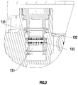
Figure 2 is a schematic view of the state of the pressure balance valve in thepreferred embodiment 1 of the present invention when the hot water inlet and the cold water inlet are both effective; -
Figure 3 is a schematic view of the state of the pressure balance valve in thepreferred embodiment 1 of the present invention when the hot water inlet and the cold water inlet are both ineffective; -
Figure 4 andFigure 5 are schematic views of the adjustment process of the temperature control valve in thepreferred embodiment 1 of the present invention; -
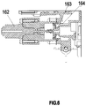
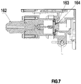
Figure 6 andFigure 7 are schematic views of the adjustment process of the flow control valve in thepreferred embodiment 1 of the present invention; -
Fig. 8 is a schematic view of showing the installation of the outlet control system when it is in a concealed way in thepreferred embodiment 2 of the present invention . - The invention will now be described in further detail with reference to the accompanying drawings and specific embodiments.
- A shower control system includes a
controller 1 and acontrol panel 2;
Referring toFIG.1 , thecontroller 1 comprises a cold water inletend 11 and a hot water inletend 12 ,the cold water and hot water flow into the twochambers 131 of thepressure balance valve 13 via the coldwater inlet end 11 and the hot water inletend 12 respectively;
the twochambers 131 of thepressure balance valve 13 flow into themixing water chamber 143 of thetemperature control valve 14 through thecold water inlet 141 and thehot water inlet 142, respectively, and thetemperature control valve 14 is controlled by thefirst stepping motor 15 ,the ratio of the hot and cold water in themixed water chamber 143 is adjusted by adjusting the water passing area of thecold water inlet 141 and thehot water inlet 142;
thecontroller 1 is provided with apressure balance valve 13 at the cold water inletend 11 and the hot water inletend 12,so that regardless of the existence of water pressure imbalance in the cold water inletend 11 and the hot water inletend 12 , the water pressure from cold water and hot water out of thebalance valve 13 can be in the roughly same state; so that in the follow-up temperature adjustment of thetemperature control valve 14 ,the pressure of the water flowing in thehot water inlet 141 and thehot water inlet 142 in thetemperature control valve 14 is roughly the same, therefore as long as the water passing area of thecold water inlet 141 and thehot water inlet 142 of thetemperature control valve 14 changes, the propotion of the hot and cold water in themixed water chamber 143 can be effectively changed, and the water temperature of the mixed water can be further changed. - The
temperature control valve 14 also includes a mixedwater outlet 146 which communicates with theflow regulating valve 16, and theflow regulating valve 16 includes a pilot valve 161 and asecond stepping motor 162, and thesecond stepping motor 162 adjusts the water passing area of theoutlet port 164 of the pilot valve 161;
theoutlet port 164 of the pilot valve 161 is communicated to the first water outlet end 17 and the secondwater outlet end 18; the first water outlet end 17 and the secondwater outlet end 18 are provided with aelectromagnetic valve 19 for controlling the opening or closing of it , respectively; in the present embodiment, the first water outlet end 17 is connected to the hand shower, and the second outlet end is connected to the top spray shower; if the user's shower room also has a bathtub, thecontroller 1 may be provided with a third water outlet which is connected to the bathtub, which is a simple modification of the above-described embodiments, and will not be described again. - Referring to
FIG. 2-3 , saidpressure balance valve 13 includes astationary member 132 and a movingmember 133,thestationary member 132 has a cavity , the side wall of thestationary member 132 has an opening communicating with the cavity ;said movingmember 133 is disposed within the cavity, divide the cavity into said twochambers 131 ,and an over-flow port is formed between the upper end of the moving member and the upper surface of the open end, and an over-flow port is formed between the lower end of the moving member and the lower surface of the open end;
when the cold water and the hot water flow into the twochambers 131, the cold water and the hot water in the chamber respectively apply pressure in the opposite direction to the movingmember 133, and when the two pressures are not equal, the movingmember 133 moves to thechamber 131 which the water pressure is higher; the over-flow port of thechamber 131 with a large pressure becomes smaller and the over-flow port of thechamber 131 with a small pressure becomes larger, so that the twochambers 131 are returned to the equilibrium state. - Therefore, when there is no hot water inflow at the hot
water inlet end 12, the movingmember 133 is moved toward thecorresponding chamber 131 of the cold water inletend 11 until the overcurrent port of thechamber 131 is blocked ,vice versa. Thus, when the hot water inletend 12 or the cold water inletend 11 is deactivated, there is no water flowing into thetemperature control valve 14 in thepressure balance valve 13, thereby preventing pure water or pure hot water from flowing out and causing damage to the user. - Referring to
Figures 4-5 , saidtemperature control valve 14 comprises a nestedset regulating member 144 and a nestedset fixing member 145, said regulatingmember 144 is moved along the axial direction of thefixing member 145 with respect to thefixing member 145 by the action of thefirst step motor 15; and the side walls of the regulatingmember 144 and thefixing member 145 are provided with two water passages; and the water inlet of the regulatingmember 144 and thefixing member 145 are communicated with each other to form thecold water inlet 141 and thehot water inlet 142; and when the regulatingmember 144 is moved in the axial direction with respect to thefixing member 145, the area where the water inlet of the regulatingmember 144 and the water inlet of thefixing member 145 coincide are changed so that the water passing area of the cold water inlet and the hot water inlet changes.Thereby the proportion of hot and cold water in themixing water chamber 143 is changed. - In order to realize that the controller can precisely adjust the proportion of hot and cold water in the mixing
water chamber 143, acold water inlet 141 and ahot water inlet 142 are provided with atemperature sensor 147 through which the cold water inlet temperature and hot water inlet temperature can be detected. - When the cold water and hot water mixed, the cold water temperature increases, the temperature of hot water decreases, so the heat Q absorbed by cold water should be equal to the heat Q released by hot water so there are:

- The above formula can be further modified as: Mcold / Mhot = (Thot-Tout)/(Tout-Tcold). In this way, the proportion of the total amount of cold water and the hot water in the
mixed water chamber 143 is calculated, and the controller controls thefirst stepper motor 15 to rotate according to the ratio, so as to achieve the purpose of accurately adjusting the water temperature. Compared with the traditional use of temperature package to adjust the temperature ,in this embodiment it is the active thermostat and is faster and more accurate than passive thermostat. - In addition, according to a certain system of products, water outlet formula:
-

- Referring to
Figures 6-7 , said pilot valve 161 includes awater blocking plug 163 disposed coaxially with the water outlet of said pilot valve 161, when saidsecond stepping motor 162 is rotated, thesecond stepping motor 162 output shaft is moved axially toward the direction of thewater blocking plug 163, and the ejection force generated between thesecond stepping motor 162 and thewater blocking plug 163 urges thewater blocking plug 163 to extend axially into thewater outlet 164 ; the outer periphery of saidwater blocking plug 163 has a circular mesa and the distance between said circular mesa and said water outlet is reduced as thewater blocking plug 163 extends into saidwater outlet 164 so that the water passing area of saidwater outlet 164 is reduced.This will achieve the purpose of flow regulation. - The
cold water inlet 141, thehot water inlet 142, and themixed water outlet 146 are respectively provided with a temperature sensor. - The above-mentioned electronic intelligent water control system which uses a stepping motor to drive the temperature control valve and the flow control valve to rotate. The temperature and flow adjustment accuracy is relatively high, the adjustment speed is relatively fast. And with this structure, the current required to drive the stepper motor is relatively small, and the controller can perform the above-mentioned control process even if the built-in power supply is used. The traditional controller needs to connect to the city electricity, and there are some hidden dangers in the shower with heavier water vapor,the invention can avoid this drawback. In contrast, the
control panel 2 can also use the built-in battery mode, or take power from the controller. Therefore, by integrating thecontrol panel 2 and thecontroller 1, thecontroller 1 is mounted in such a manner that the conventional shower controller is replaced with the above-described electronic intelligence water control system without damaging the mounting wall of the original waterway . So that the cost of replace is very low, those who have completed the renovation can also choose to use the electronic intelligent water control system. - In the present embodiment, the control panel is provided on the surface of the controller ,and has several discrete buttons, and when the user presses a different button, the
control panel 2 sends an input signal to the controller, and the signal is transferred to the electrical signal of controlling the first stepping motor, the second stepper motor, the electromagnetic valve , so you can achieve the adjustment of water temperature, flow, water terminal. - Referring to
Fig. 8 , in the present embodiment, thecontroller 1 is provided separately from thecontrol panel 2, and thecontroller 1 is mounted in a concealed manner. This way is suitable for new home installation of the user, you can hide thecontroller 1, save the shower room space, also makes the whole shower room more simple and beautiful. - When the
controller 1 is mounted in a concealed manner, thecontrol panel 2 is mounted on the wall and electrically connected to thecontroller 1. Thecontrol panel 2 can be powered by thecontroller 1, or the control panel itself has a built-in power supply. - The present invention may be summarized as follows: The present invention provides an electronic intelligent water outlet control system comprising: a controller and a control panel; the controller comprises a cold water inlet end and a hot water inlet end, the, cold water and the hot water flow through said cold water inlet end and hot water inlet end respectively into two chambers of a pressure balance valve; the two chambers of the pressure balance valve respectively flow into the mixing water chamber of the temperature control valve through the cold water inlet and the hot water inlet,the temperature control valve is regulated by the first stepping motor to regulate the water passing area of the cold water inlet and hot water inlet ;the temperature control valve also includes a mixed water outlet connected to the flow control valve; the flow control valve includes a pilot valve and a second stepping motor, the pilot valve outlet is connected to the first water outlet end and the second outlet end,the first outlet end and the second outlet end are respectively provided with an electromagnetic valve to control the opening or closing of the the first outlet end and the second outlet end.The invention provides an electronic intelligent water outlet control system, which is compact and can adjust the water flow and water temperature accurately, and is convenient for users to use.
- The foregoing is intended to be a preferred embodiment of the present invention, but the scope of the invention is not limited thereto, and any person skilled in the art will be able to easily think of changes within the scope of the invention disclosed. Substitutions are to be covered within the scope of the present invention. Accordingly, the scope of protection of the present invention should be determined by the scope of the claims.
Claims (9)
- An electronic intelligent water outlet control system, wherein comprising: a controller and a control panel;
said controller comprises a cold water inlet end and hot water inlet end, the cold water and the hot water flow through said cold water inlet end and hot water inlet end respectively into two chambers of a pressure balance valve;the two chambers of the pressure balance valve respectively flow into the mixing water chamber of the temperature control valve through the cold water inlet and the hot water inlet, the temperature control valve is regulated by the first stepping motor to regulate the water passing area of the cold water inlet and hot water inlet so as to adjust the proportion of hot and cold water in the mixing water chamber;the temperature control valve further comprises a mixed water outlet connected to the flow control valve; the flow control valve comprises a pilot valve and a second stepping motor, the second stepping motor adjusts the water passing area of the pilot valve outlet;the pilot valve outlet is connected to the first water outlet end and the second outlet end; the first outlet end and the second outlet end are respectively provided with an electromagnetic valve to control the opening or closing of the the first outlet end and the second outlet end;the control panel sends a water terminal selection signal to the controller, the controller generates an electrical signal to control the open of the first water outlet terminal or the second water outlet terminal ; the control panel also sends a temperature adjustment signal and the flow rate adjustment signal to the the controller, the controller generates an electrical signal to control the first stepping motor ,the second stepping motor is rotated an angle so that the outlet water temperature of the mixed water outlet of the temperature control valve is increased or decreased and the outlet water flow of the flow control valve is increased or decreased;
the cold water inlet and the hot water inlet are respectively provided with a temperature sensor for detecting the water temperature of the cold water and the hot water. When the controller receives the temperature adjustment signal; the proportion of the cold water and the hot water is calculated according to the water temperature of the cold water and the hot water when the temperature of the mixed water outlet water reach the requirement of the temperature regulation signal ,and then the first stepper motor rotation corresponding angle is in control;
the proportion of cold water and hot water is calculated as follows:
- The electronic intelligent water outlet control system according to claim 1, wherein said temperature control valve comprises a nested set regulating member and a nested set fixing member, said regulating member is moved along the axial direction of the fixing member with respect to the fixing member by the action of the first step motor ;and the side walls of the regulating member and the fixing member are provided with two water passages; and the water inlet of the regulating member and the fixing member are communicated with each other to form the cold water inlet and the hot water inlet; and when the regulating member is moved in the axial direction with respect to the fixing member, the area where the water inlet of the regulating member and the water inlet of the fixing member coincide are changed so that the water passing area of the cold water inlet and the hot water inlet changes.
- The electronic intelligent water outlet control system according to claim 1 and/or 2, wherein said pressure balance valve includes a stationary member and a moving member,the stationary member has a cavity , the side wall of the stationary member has an opening communicating with the cavity ;said moving member is disposed within the cavity, divide the cavity into said two chambers,and an over-flow port is formed between the upper end of the moving member and the upper surface of the open end, and an over-flow port is formed between the lower end of the moving member and the lower surface of the open end;
when the cold water and the hot water flow into the two chambers, the cold water and the hot water in the chamber respectively apply pressure in the opposite direction to the moving member, and when the two pressures are not equal, the moving member moves to the chamber which the water pressure is lower; the over-flow port of the chamber with a large pressure becomes smaller and the over-flow port of the chamber with a small pressure becomes larger, so that the two chambers are returned to the equilibrium state. - The electronic intelligent water outlet control system according to any one or more of claims 1 to 3, wherein said pilot valve includes a water blocking plug disposed coaxially with the water outlet of said pilot valve, when said second stepping motor is rotated, the second stepping motor output shaft is moved axially toward the direction of the water blocking plug, and the ejection force generated between the second stepping motor and the water blocking plug urges the water blocking plug to extend axially into the water outlet; the outer periphery of said water blocking plug has a circular mesa and the distance between said circular mesa and said water outlet is reduced as the water blocking plug extends into said water outlet so that the water passing area of said water outlet is reduced.
- The electronic intelligent water outlet control system according to any one or more of claims 1 to 4, wherein the mixed water outlet is also provided with a temperature sensor
- The electronic intelligent control system according to any one or more of claims 1 to 5, wherein said controller is mounted outside and comprises an outer housing; said control panel is provided in the surface of the outer housing.
- The electronic intelligent water outlet control system according to claim 6, wherein the housing is further provided with a built-in power supply for supplying power to the controller and the control panel.
- The electronic intelligent water outlet control system according to any one or more of claims 1 to 5, wherein said controller is mounted in a concealed manner, the control panel is provided separately from the controller, and the controller and the control panel are electrically connected by wires.
- The electronic intelligent water outlet control system according to claim 8, wherein said controller is electrically connected to the city electricity.
Applications Claiming Priority (1)
| Application Number | Priority Date | Filing Date | Title |
|---|---|---|---|
| CN201710379097.5A CN108958317A (en) | 2017-05-25 | 2017-05-25 | A kind of electronic intelligence outlet controlling system |
Publications (1)
| Publication Number | Publication Date |
|---|---|
| EP3407154A1 true EP3407154A1 (en) | 2018-11-28 |
Family
ID=61163466
Family Applications (1)
| Application Number | Title | Priority Date | Filing Date |
|---|---|---|---|
| EP18000082.0A Ceased EP3407154A1 (en) | 2017-05-25 | 2018-02-01 | An electronic intelligent water outlet control system |
Country Status (2)
| Country | Link |
|---|---|
| EP (1) | EP3407154A1 (en) |
| CN (1) | CN108958317A (en) |
Cited By (3)
| Publication number | Priority date | Publication date | Assignee | Title |
|---|---|---|---|---|
| CN112254240A (en) * | 2020-11-13 | 2021-01-22 | 江苏达实久信医疗科技有限公司 | Operating room integrated intelligent water air conditioner actuator |
| CN112696509A (en) * | 2021-01-05 | 2021-04-23 | 浙江高澳卫浴有限公司 | Bathroom shower controller |
| CN115875496A (en) * | 2022-11-16 | 2023-03-31 | 浙江鑫东洁具有限公司 | A multifunctional integrated thermostat |
Families Citing this family (1)
| Publication number | Priority date | Publication date | Assignee | Title |
|---|---|---|---|---|
| CN116025757A (en) * | 2023-01-17 | 2023-04-28 | 福州锐洁源电子科技有限公司 | A control method for a thermostat valve system for cold and heat regulation |
Citations (2)
| Publication number | Priority date | Publication date | Assignee | Title |
|---|---|---|---|---|
| EP0358173A2 (en) * | 1988-09-06 | 1990-03-14 | Matsushita Electric Industrial Co., Ltd. | Automatic hot water supply apparatus |
| EP2136278A1 (en) * | 2008-06-16 | 2009-12-23 | Fabrizio Nobili | Thermostatic mixer |
Family Cites Families (6)
| Publication number | Priority date | Publication date | Assignee | Title |
|---|---|---|---|---|
| CN201297773Y (en) * | 2008-08-27 | 2009-08-26 | 厦门市易洁卫浴有限公司 | Electronic accurate temperature control device |
| CN201306469Y (en) * | 2008-11-27 | 2009-09-09 | 深圳成霖洁具股份有限公司 | Water flow temperature controlling system |
| CN104422133B (en) * | 2013-08-19 | 2018-09-11 | 珠海格力电器股份有限公司 | Hot water system and control method of water mixing valve thereof |
| CN103884105B (en) * | 2014-02-10 | 2016-04-27 | 浙江大学 | A kind of constant-temperature bathing system |
| CN105466027A (en) * | 2014-09-09 | 2016-04-06 | 芜湖美的厨卫电器制造有限公司 | Electric water heater and constant temperature control device and method thereof |
| CN104776250A (en) * | 2015-04-29 | 2015-07-15 | 河南师范大学 | Intelligent constant-temperature water outlet control device |
-
2017
- 2017-05-25 CN CN201710379097.5A patent/CN108958317A/en active Pending
-
2018
- 2018-02-01 EP EP18000082.0A patent/EP3407154A1/en not_active Ceased
Patent Citations (2)
| Publication number | Priority date | Publication date | Assignee | Title |
|---|---|---|---|---|
| EP0358173A2 (en) * | 1988-09-06 | 1990-03-14 | Matsushita Electric Industrial Co., Ltd. | Automatic hot water supply apparatus |
| EP2136278A1 (en) * | 2008-06-16 | 2009-12-23 | Fabrizio Nobili | Thermostatic mixer |
Cited By (3)
| Publication number | Priority date | Publication date | Assignee | Title |
|---|---|---|---|---|
| CN112254240A (en) * | 2020-11-13 | 2021-01-22 | 江苏达实久信医疗科技有限公司 | Operating room integrated intelligent water air conditioner actuator |
| CN112696509A (en) * | 2021-01-05 | 2021-04-23 | 浙江高澳卫浴有限公司 | Bathroom shower controller |
| CN115875496A (en) * | 2022-11-16 | 2023-03-31 | 浙江鑫东洁具有限公司 | A multifunctional integrated thermostat |
Also Published As
| Publication number | Publication date |
|---|---|
| CN108958317A (en) | 2018-12-07 |
Similar Documents
| Publication | Publication Date | Title |
|---|---|---|
| JP6138718B2 (en) | Control unit for mixed faucet and temperature control device for mixed faucet | |
| US5944255A (en) | Shower water automatic temperature controller | |
| EP3952707B1 (en) | Electronic showerhead device | |
| CN108953749B (en) | Shower bath control system | |
| CN101900216B (en) | Discharge mechanism capable of controlling water temperature and flow | |
| CN105466027A (en) | Electric water heater and constant temperature control device and method thereof | |
| CN103743114A (en) | Water temperature automatic control circuit for temperature constant water heater | |
| CN104595526A (en) | Memory alloy constant-temperature water faucet | |
| WO2009135434A1 (en) | Intelligent water supply central processor and water faucet | |
| CN108958317A (en) | A kind of electronic intelligence outlet controlling system | |
| CN104500786A (en) | Intelligent constant-temperature control device | |
| CN201575197U (en) | Electronic automatic and manual adjustment dual-use multifunctional outlet constant temperature water mixing valve | |
| US20130081713A1 (en) | Capacitive hand free automatic mixing faucet and control method | |
| CN207457861U (en) | Electronic intelligence outlet controlling system | |
| CN206988552U (en) | Take a shower control system | |
| JPH0547844B2 (en) | ||
| CN213145465U (en) | Multifunctional energy-saving water mixing valve | |
| CN210423821U (en) | Self-generating faucet | |
| JPH06257572A (en) | Controller for operation of direct coupled feed water supply system | |
| JP2018071840A (en) | Hot water supply system | |
| CN204387403U (en) | Intelligent thermostatic control device | |
| CN111102631B (en) | Expansion tank and dual-purpose furnace applying same | |
| CN111596703B (en) | Automatic temperature-adjusting bathing control device and method | |
| GB2295469A (en) | Power regulation of central heating pump | |
| JP2663609B2 (en) | Hot water mixing equipment |
Legal Events
| Date | Code | Title | Description |
|---|---|---|---|
| PUAI | Public reference made under article 153(3) epc to a published international application that has entered the european phase |
Free format text: ORIGINAL CODE: 0009012 |
|
| AK | Designated contracting states |
Kind code of ref document: A1 Designated state(s): AL AT BE BG CH CY CZ DE DK EE ES FI FR GB GR HR HU IE IS IT LI LT LU LV MC MK MT NL NO PL PT RO RS SE SI SK SM TR |
|
| AX | Request for extension of the european patent |
Extension state: BA ME |
|
| 17P | Request for examination filed |
Effective date: 20190527 |
|
| RBV | Designated contracting states (corrected) |
Designated state(s): AL AT BE BG CH CY CZ DE DK EE ES FI FR GB GR HR HU IE IS IT LI LT LU LV MC MK MT NL NO PL PT RO RS SE SI SK SM TR |
|
| 17Q | First examination report despatched |
Effective date: 20190807 |
|
| STAA | Information on the status of an ep patent application or granted ep patent |
Free format text: STATUS: THE APPLICATION HAS BEEN REFUSED |
|
| 18R | Application refused |
Effective date: 20201208 |