EP3407126A1 - Liquid-crystal display device and light-source device - Google Patents
Liquid-crystal display device and light-source device Download PDFInfo
- Publication number
- EP3407126A1 EP3407126A1 EP18173086.2A EP18173086A EP3407126A1 EP 3407126 A1 EP3407126 A1 EP 3407126A1 EP 18173086 A EP18173086 A EP 18173086A EP 3407126 A1 EP3407126 A1 EP 3407126A1
- Authority
- EP
- European Patent Office
- Prior art keywords
- light
- source
- liquid
- scanning
- crystal display
- Prior art date
- Legal status (The legal status is an assumption and is not a legal conclusion. Google has not performed a legal analysis and makes no representation as to the accuracy of the status listed.)
- Granted
Links
Images




Classifications
-
- H—ELECTRICITY
- H05—ELECTRIC TECHNIQUES NOT OTHERWISE PROVIDED FOR
- H05B—ELECTRIC HEATING; ELECTRIC LIGHT SOURCES NOT OTHERWISE PROVIDED FOR; CIRCUIT ARRANGEMENTS FOR ELECTRIC LIGHT SOURCES, IN GENERAL
- H05B45/00—Circuit arrangements for operating light-emitting diodes [LED]
- H05B45/10—Controlling the intensity of the light
-
- G—PHYSICS
- G02—OPTICS
- G02F—OPTICAL DEVICES OR ARRANGEMENTS FOR THE CONTROL OF LIGHT BY MODIFICATION OF THE OPTICAL PROPERTIES OF THE MEDIA OF THE ELEMENTS INVOLVED THEREIN; NON-LINEAR OPTICS; FREQUENCY-CHANGING OF LIGHT; OPTICAL LOGIC ELEMENTS; OPTICAL ANALOGUE/DIGITAL CONVERTERS
- G02F1/00—Devices or arrangements for the control of the intensity, colour, phase, polarisation or direction of light arriving from an independent light source, e.g. switching, gating or modulating; Non-linear optics
- G02F1/01—Devices or arrangements for the control of the intensity, colour, phase, polarisation or direction of light arriving from an independent light source, e.g. switching, gating or modulating; Non-linear optics for the control of the intensity, phase, polarisation or colour
- G02F1/13—Devices or arrangements for the control of the intensity, colour, phase, polarisation or direction of light arriving from an independent light source, e.g. switching, gating or modulating; Non-linear optics for the control of the intensity, phase, polarisation or colour based on liquid crystals, e.g. single liquid crystal display cells
- G02F1/133—Constructional arrangements; Operation of liquid crystal cells; Circuit arrangements
- G02F1/1333—Constructional arrangements; Manufacturing methods
- G02F1/1335—Structural association of cells with optical devices, e.g. polarisers or reflectors
- G02F1/1336—Illuminating devices
- G02F1/133615—Edge-illuminating devices, i.e. illuminating from the side
-
- G—PHYSICS
- G02—OPTICS
- G02B—OPTICAL ELEMENTS, SYSTEMS OR APPARATUS
- G02B26/00—Optical devices or arrangements for the control of light using movable or deformable optical elements
- G02B26/08—Optical devices or arrangements for the control of light using movable or deformable optical elements for controlling the direction of light
- G02B26/10—Scanning systems
-
- G—PHYSICS
- G02—OPTICS
- G02B—OPTICAL ELEMENTS, SYSTEMS OR APPARATUS
- G02B6/00—Light guides; Structural details of arrangements comprising light guides and other optical elements, e.g. couplings
- G02B6/0001—Light guides; Structural details of arrangements comprising light guides and other optical elements, e.g. couplings specially adapted for lighting devices or systems
- G02B6/0011—Light guides; Structural details of arrangements comprising light guides and other optical elements, e.g. couplings specially adapted for lighting devices or systems the light guides being planar or of plate-like form
- G02B6/0013—Means for improving the coupling-in of light from the light source into the light guide
- G02B6/0023—Means for improving the coupling-in of light from the light source into the light guide provided by one optical element, or plurality thereof, placed between the light guide and the light source, or around the light source
- G02B6/0031—Reflecting element, sheet or layer
-
- G—PHYSICS
- G02—OPTICS
- G02F—OPTICAL DEVICES OR ARRANGEMENTS FOR THE CONTROL OF LIGHT BY MODIFICATION OF THE OPTICAL PROPERTIES OF THE MEDIA OF THE ELEMENTS INVOLVED THEREIN; NON-LINEAR OPTICS; FREQUENCY-CHANGING OF LIGHT; OPTICAL LOGIC ELEMENTS; OPTICAL ANALOGUE/DIGITAL CONVERTERS
- G02F1/00—Devices or arrangements for the control of the intensity, colour, phase, polarisation or direction of light arriving from an independent light source, e.g. switching, gating or modulating; Non-linear optics
- G02F1/01—Devices or arrangements for the control of the intensity, colour, phase, polarisation or direction of light arriving from an independent light source, e.g. switching, gating or modulating; Non-linear optics for the control of the intensity, phase, polarisation or colour
- G02F1/13—Devices or arrangements for the control of the intensity, colour, phase, polarisation or direction of light arriving from an independent light source, e.g. switching, gating or modulating; Non-linear optics for the control of the intensity, phase, polarisation or colour based on liquid crystals, e.g. single liquid crystal display cells
- G02F1/133—Constructional arrangements; Operation of liquid crystal cells; Circuit arrangements
- G02F1/1333—Constructional arrangements; Manufacturing methods
- G02F1/1335—Structural association of cells with optical devices, e.g. polarisers or reflectors
- G02F1/133504—Diffusing, scattering, diffracting elements
-
- G—PHYSICS
- G02—OPTICS
- G02F—OPTICAL DEVICES OR ARRANGEMENTS FOR THE CONTROL OF LIGHT BY MODIFICATION OF THE OPTICAL PROPERTIES OF THE MEDIA OF THE ELEMENTS INVOLVED THEREIN; NON-LINEAR OPTICS; FREQUENCY-CHANGING OF LIGHT; OPTICAL LOGIC ELEMENTS; OPTICAL ANALOGUE/DIGITAL CONVERTERS
- G02F1/00—Devices or arrangements for the control of the intensity, colour, phase, polarisation or direction of light arriving from an independent light source, e.g. switching, gating or modulating; Non-linear optics
- G02F1/01—Devices or arrangements for the control of the intensity, colour, phase, polarisation or direction of light arriving from an independent light source, e.g. switching, gating or modulating; Non-linear optics for the control of the intensity, phase, polarisation or colour
- G02F1/13—Devices or arrangements for the control of the intensity, colour, phase, polarisation or direction of light arriving from an independent light source, e.g. switching, gating or modulating; Non-linear optics for the control of the intensity, phase, polarisation or colour based on liquid crystals, e.g. single liquid crystal display cells
- G02F1/133—Constructional arrangements; Operation of liquid crystal cells; Circuit arrangements
- G02F1/1333—Constructional arrangements; Manufacturing methods
- G02F1/1335—Structural association of cells with optical devices, e.g. polarisers or reflectors
- G02F1/133553—Reflecting elements
-
- G—PHYSICS
- G02—OPTICS
- G02F—OPTICAL DEVICES OR ARRANGEMENTS FOR THE CONTROL OF LIGHT BY MODIFICATION OF THE OPTICAL PROPERTIES OF THE MEDIA OF THE ELEMENTS INVOLVED THEREIN; NON-LINEAR OPTICS; FREQUENCY-CHANGING OF LIGHT; OPTICAL LOGIC ELEMENTS; OPTICAL ANALOGUE/DIGITAL CONVERTERS
- G02F1/00—Devices or arrangements for the control of the intensity, colour, phase, polarisation or direction of light arriving from an independent light source, e.g. switching, gating or modulating; Non-linear optics
- G02F1/01—Devices or arrangements for the control of the intensity, colour, phase, polarisation or direction of light arriving from an independent light source, e.g. switching, gating or modulating; Non-linear optics for the control of the intensity, phase, polarisation or colour
- G02F1/13—Devices or arrangements for the control of the intensity, colour, phase, polarisation or direction of light arriving from an independent light source, e.g. switching, gating or modulating; Non-linear optics for the control of the intensity, phase, polarisation or colour based on liquid crystals, e.g. single liquid crystal display cells
- G02F1/133—Constructional arrangements; Operation of liquid crystal cells; Circuit arrangements
- G02F1/1333—Constructional arrangements; Manufacturing methods
- G02F1/1335—Structural association of cells with optical devices, e.g. polarisers or reflectors
- G02F1/1336—Illuminating devices
-
- G—PHYSICS
- G02—OPTICS
- G02F—OPTICAL DEVICES OR ARRANGEMENTS FOR THE CONTROL OF LIGHT BY MODIFICATION OF THE OPTICAL PROPERTIES OF THE MEDIA OF THE ELEMENTS INVOLVED THEREIN; NON-LINEAR OPTICS; FREQUENCY-CHANGING OF LIGHT; OPTICAL LOGIC ELEMENTS; OPTICAL ANALOGUE/DIGITAL CONVERTERS
- G02F1/00—Devices or arrangements for the control of the intensity, colour, phase, polarisation or direction of light arriving from an independent light source, e.g. switching, gating or modulating; Non-linear optics
- G02F1/01—Devices or arrangements for the control of the intensity, colour, phase, polarisation or direction of light arriving from an independent light source, e.g. switching, gating or modulating; Non-linear optics for the control of the intensity, phase, polarisation or colour
- G02F1/13—Devices or arrangements for the control of the intensity, colour, phase, polarisation or direction of light arriving from an independent light source, e.g. switching, gating or modulating; Non-linear optics for the control of the intensity, phase, polarisation or colour based on liquid crystals, e.g. single liquid crystal display cells
- G02F1/133—Constructional arrangements; Operation of liquid crystal cells; Circuit arrangements
- G02F1/1333—Constructional arrangements; Manufacturing methods
- G02F1/1335—Structural association of cells with optical devices, e.g. polarisers or reflectors
- G02F1/1336—Illuminating devices
- G02F1/133602—Direct backlight
- G02F1/133603—Direct backlight with LEDs
-
- G—PHYSICS
- G06—COMPUTING OR CALCULATING; COUNTING
- G06F—ELECTRIC DIGITAL DATA PROCESSING
- G06F3/00—Input arrangements for transferring data to be processed into a form capable of being handled by the computer; Output arrangements for transferring data from processing unit to output unit, e.g. interface arrangements
- G06F3/01—Input arrangements or combined input and output arrangements for interaction between user and computer
- G06F3/03—Arrangements for converting the position or the displacement of a member into a coded form
- G06F3/041—Digitisers, e.g. for touch screens or touch pads, characterised by the transducing means
- G06F3/0416—Control or interface arrangements specially adapted for digitisers
-
- G—PHYSICS
- G02—OPTICS
- G02F—OPTICAL DEVICES OR ARRANGEMENTS FOR THE CONTROL OF LIGHT BY MODIFICATION OF THE OPTICAL PROPERTIES OF THE MEDIA OF THE ELEMENTS INVOLVED THEREIN; NON-LINEAR OPTICS; FREQUENCY-CHANGING OF LIGHT; OPTICAL LOGIC ELEMENTS; OPTICAL ANALOGUE/DIGITAL CONVERTERS
- G02F1/00—Devices or arrangements for the control of the intensity, colour, phase, polarisation or direction of light arriving from an independent light source, e.g. switching, gating or modulating; Non-linear optics
- G02F1/01—Devices or arrangements for the control of the intensity, colour, phase, polarisation or direction of light arriving from an independent light source, e.g. switching, gating or modulating; Non-linear optics for the control of the intensity, phase, polarisation or colour
- G02F1/13—Devices or arrangements for the control of the intensity, colour, phase, polarisation or direction of light arriving from an independent light source, e.g. switching, gating or modulating; Non-linear optics for the control of the intensity, phase, polarisation or colour based on liquid crystals, e.g. single liquid crystal display cells
- G02F1/133—Constructional arrangements; Operation of liquid crystal cells; Circuit arrangements
- G02F1/1333—Constructional arrangements; Manufacturing methods
- G02F1/1335—Structural association of cells with optical devices, e.g. polarisers or reflectors
- G02F1/1336—Illuminating devices
- G02F1/133601—Illuminating devices for spatial active dimming
-
- G—PHYSICS
- G02—OPTICS
- G02F—OPTICAL DEVICES OR ARRANGEMENTS FOR THE CONTROL OF LIGHT BY MODIFICATION OF THE OPTICAL PROPERTIES OF THE MEDIA OF THE ELEMENTS INVOLVED THEREIN; NON-LINEAR OPTICS; FREQUENCY-CHANGING OF LIGHT; OPTICAL LOGIC ELEMENTS; OPTICAL ANALOGUE/DIGITAL CONVERTERS
- G02F2203/00—Function characteristic
- G02F2203/24—Function characteristic beam steering
Definitions
- This invention relates to a liquid-crystal display device and a light-source device and particularly relates to a liquid-crystal display device and a light-source device that includes a plurality of light sources.
- Conventional liquid-crystal display devices and light-source devices include a plurality of light sources are known (for example, see patent literature 1).
- Patent literature 1 discloses a light-source device where local dimming control is possible.
- Local dimming control is a technique of partially changing a brightness of a backlight of a liquid-crystal display device and increasing a contrast of a display image by individually controlling emission brightnesses of a plurality of light sources.
- the light-source device of patent literature 1 has a plurality of divided regions (emission blocks) where emission brightnesses can be changed individually and, with no less than one divided region as one emission unit, is configured so light sources can perform emission at predetermined emission brightnesses for each emission unit.
- one lighting unit includes a green laser diode (LD) to increase a purity of a green component transmitted from a green color filter of a liquid-crystal display panel.
- one lighting unit further includes blue and red Light Emitting Diode (LED) light sources whose directionalities are wider than those of a laser-diode light source.
- LD green laser diode
- LED Light Emitting Diode
- Patent Literature 1 JP2016-35908 A
- One or more embodiments of the present invention provide a liquid-crystal display device and a light-source device that can improve a precision of brightness control while suppressing an increased component count in local dimming control.
- a liquid-crystal display device includes a display, a plurality of first light sources that emits a light to a face on an opposite side of a display face of the display, a second light source that differs from the first light source, and a scanner that scans a light emitted from the second light source to the face on the opposite side of the display face.
- a light can be irradiated to a predetermined region of the face on the opposite side of the display face by scanning the light emitted from the second light source.
- the predetermined region in the display can be locally irradiated by the light emitted from the second light source without increasing a number of first light sources. That is, a region where brightness control is possible can be subdivided without increasing the number of first light sources. By this, a precision in brightness control can be improved while suppressing an increased component count.
- the second light source is scanned so the light thereof overlaps the light emitted from the first light source in the predetermined region in the region whereto the light is being irradiated by the first light source.
- the light emitted from the second light source is overlapped on the light emitted from the first light source while changing a light amount of the light emitted from the second light source.
- the brightness of the predetermined region can be readily increased while performing local dimming control by changing the light amount of the second light source when scanning the predetermined region.
- a plurality of scanning light-source units is provided, each including the second light source and the scanner.
- the display has a substantially rectangular shape and, viewed from a direction perpendicular to the display, each of the plurality of scanning light-source units is provided near a side of the substantially rectangular display, these sides being an opposing pair.
- each of the plurality of scanning light-source units is provided near a side of the substantially rectangular display, these sides being an opposing pair.
- the scanning light-source unit provided to one side among the pair of sides can scan within the display on another side (or one side) of the pair of sides relative to a center of the display and the scanning light-source unit provided to the other side among the pair of sides can scan within the display on the one side (or the other side) of the pair of sides relative to the center of the display.
- an excessive burden being applied on one of the plurality of scanning light-source units can be suppressed because sizes of the regions respectively scanned by the plurality of scanning light-source units can be made substantially identical.
- Near a pair of sides signifies both a position per se of the pair of sides and a vicinity of the position of the pair of sides.
- the plurality of scanning light-source units is disposed on a common base.
- an operation efficiency in installing the scanning light-source units can be improved because two scanning light-source units can be installed simultaneously by installing the base whereon the plurality of scanning light-source units is disposed.
- a shift in installation position between the two scanning light-source units can be suppressed from arising.
- a liquid-crystal display device includes a reflective portion that, viewed from a direction perpendicular to the display face, is provided along an outer periphery of the display face and reflects the light emitted from the second light source to the face on the opposite side of the display face.
- a liquid-crystal display device includes a reflective sheet that reflects the light radiated from the first light source to a display-unit side.
- the reflective portion is formed by a vicinity of an outer peripheral edge of the reflective sheet being bent to the display-unit side. By configuring in this manner, an increased component count can be suppressed because the reflective portion can be formed using the reflective sheet that is already provided.
- "Vicinity of outer peripheral edge" signifies a vicinity of a position of the outer peripheral edge.
- a liquid-crystal display device includes a light guide member that is provided between the display and the first light source and orients the light emitted from the second light source to the display-unit side. By configuring in this manner, the light emitted from the second light source can be readily irradiated to a region comparatively separated from the second light source by the light guide member.
- a liquid-crystal display device includes the first light source that includes a direct LED light source disposed so as to oppose the display and the second light source that includes a laser light source.
- a light emitted from the laser light source has a comparatively higher directionality than a light emitted from the LED light source. Therefore, by scanning by the second light source that includes the laser light source, a precision in brightness control can be readily increased.
- a light-source device includes a plurality of first light sources; a second light source that differs from the first light source and a scanner that scans a light emitted from the second light source.
- the scanner that scans the light emitted from the second light source by the scanner that scans the light emitted from the second light source being provided, the light emitted from the second light source can be scanned in a predetermined region.
- the predetermined region can be locally irradiated by the light emitted from the second light source without increasing a number of first light sources.
- One or more embodiments of the present invention provides a liquid-crystal display device that includes a display that comprises a display face, a plurality of first light sources, each of which emits a first light to a face on an opposite side of the display face, a second light source that differs from the first light source and emits a second light, and a scanner that scans the second light in the face.
- a precision of brightness control can be improved while suppressing an increased component count in local dimming control.
- FIGS. 1 to 7(b) are schematic views; for simplification, illustration is omitted for members unnecessary in the description.
- the liquid-crystal display device 100 includes a display cell 1 that includes a display face 1a.
- the display cell 1 has a substantially rectangular shape.
- the liquid-crystal display device 100 includes a front cabinet (front-side housing) 2 and a rear cabinet (rear-side housing) 3 that house the display cell 1.
- the display cell 1 is one example of "display.”
- the liquid-crystal display device 100 (light-source device 200) includes a plurality of LED light sources 4 and a laser light sources 5a. Moreover, the liquid-crystal display device 100 includes a reflective sheet 6 that reflects a light radiated from the LED light source 4 to a display-cell 1 side (Y1-direction side). Various optical sheets are provided between the display cell 1 and the reflective sheet 6 but are not illustrated for the sake of simplification.
- the LED light source 4 and the laser light source 5a are respectively one example of "first light source” and one example of "second light source.”
- each of the plurality of LED light sources 4 is a direct light source disposed so as to oppose the display cell 1. That is, the plurality of LED light sources 4 emits the lights to a face 1b on an opposite side of the display face 1a of the display cell 1.
- the LED light sources 4 are disposed in a matrix (see FIG. 4 ).
- Each of the plurality of LED light sources 4 is disposed on the reflective sheet 6.
- a configuration may be such that a plurality of holes is provided in the reflective sheet 6 and each of the plurality of LED light sources 4 is exposed to the display-cell 1 side (Y1-direction side) via the plurality of holes.
- the liquid-crystal display device 100 is configured so local dimming control is possible by independently controlling each of the plurality of LED light sources 4.
- the liquid-crystal display device 100 (light-source device 200) includes a scanning mirror unit 5b that scans a light emitted from the laser light source 5a on the face 1b (for example, a MEMS [microelectromechanical system] mirror, a polygon mirror, a galvano mirror, or the like).
- a scanning mirror unit 5b that scans a light emitted from the laser light source 5a on the face 1b (for example, a MEMS [microelectromechanical system] mirror, a polygon mirror, a galvano mirror, or the like).
- one laser light source 5a and one scanning mirror unit 5b are configured as a pair. That is, the liquid-crystal display device 100 includes a scanning laser light-source unit 5 that includes one pair of the laser light source 5a and the scanning mirror unit 5b.
- the scanning laser light-source unit 5 includes an optical system that is not illustrated in addition to the laser light source 5a and the scanning mirror unit 5b.
- the scanning mirror unit 5b and the scanning laser light-source unit 5 are respectively one example of "scanner” and one example of “scanning light-source unit” in one or more embodiments of the present invention.
- a plurality of scanning laser light-source units 5 is provided (in the first embodiment, two are provided).
- the plurality of scanning laser light-source units 5 is provided in substantially identical height positions in a Y direction.
- the laser light source 5a is scanned so the light thereof overlaps the light emitted from the LED light source 4 in a predetermined region in a region whereto the light is being irradiated by the LED light source 4.
- the laser light source 5a scans an entire range of the display cell 1 by the scanning mirror unit 5b. That is, each of the two laser light sources 5a scans half of the entire range of the display cell 1 (see FIG. 5 ). While in FIG. 3 the laser light source 5a is disposed on the Y1-direction side and the scanning mirror unit 5b is disposed on a Y2-direction side of the LED light source 4, disposition positions are not limited thereto.
- the first embodiment of the present invention is configured to overlap the light emitted from the laser light source 5a on the light emitted from the LED light source 4 without changing a light amount of the light emitted from the LED light source 4 but while changing a light amount of the light emitted from the laser light source 5a.
- the light amount of the laser light source 5a is increased at a timing where, while scanning the laser light source 5a, the light emitted from the laser light source 5a is being irradiated to the predetermined region.
- the light amount of the light emitted from the laser light source 5a is decreased (or made to be zero).
- the predetermined region is selected by a control unit (not illustrated) of the laser light source 5a.
- the control unit may select a region corresponding to an LED light source 4 whose light amount is comparatively large among the plurality of LED light sources 4.
- the control unit may select one or a plurality of regions.
- each of the two scanning laser light-source units 5 is provided near a side of the substantially rectangular display cell 1, these sides being an opposing pair.
- each of the two scanning laser light-source units 5 is disposed on an outer side of the display cell 1.
- the laser light source 5a (see FIG. 2 ) and the scanning mirror unit 5b (see FIG. 2 ) are each disposed so as to not overlap the display cell 1.
- the scanning mirror unit 5b is disposed on the display-cell 1 side relative to the laser light source 5a paired thereto (see FIG. 3 ).
- the two scanning laser light-source units 5 are respectively disposed near one long side 1c among a pair of long sides of the display cell 1 and near the other long side Id among the pair of long sides.
- the two scanning laser light-source units 5 are respectively disposed in a substantial center of the long side 1c and a substantial center of the long side 1d.
- the light emitted from the scanning laser light-source unit 5 near the long side 1c is scanned in a region on a lower side (Z2-direction side) of the display cell 1, and the light emitted from the scanning laser light-source unit 5 near the long side Id is scanned in a region on an upper side (Z1-direction side) of the display cell 1.
- the light emitted from the scanning laser light-source unit 5 near the long side 1c may be scanned in the region on the upper side (Z1-direction side) of the display cell 1 and the light emitted from the scanning laser light-source unit 5 near the long side Id may be scanned in the region on the lower side (Z2-direction side) of the display cell 1.
- the two scanning laser light-source units 5 are disposed on a common base 7.
- the laser light source 5a and the scanning mirror unit 5b of the scanning laser light-source unit 5 near the long side 1c and the laser light source 5a and the scanning mirror unit 5b of the scanning laser light-source unit 5 near the long side 1d are each disposed on the same base 7.
- the base 7 is made of metal.
- the base 7 is molded by aluminum, iron, or the like.
- the liquid-crystal display device 100 (light-source device 200) that includes the scanning laser light-source unit 5, the LED light source 4 and the laser light source 5a each irradiate a light to the display cell 1.
- the LED light source 4 and the laser light source 5a each irradiate a light to the display cell 1.
- control is possible so, by the light emitted from the laser light source 5a overlapping the lights emitted from the plurality of (in FIG. 6(a) , three) LED light sources 4, among the plurality of divided regions B in the display cell 1, a brightness in a range of, for example, 1 ⁇ 2 divided regions B (range of diagonal-line portion) is greater than that of another region.
- the range of the region where the brightness can be increased is but one example and is not limited thereto. That is, by providing the scanning laser light-source unit 5 (laser light source 5a), it is possible to increase a precision in brightness control.
- the first embodiment of the present invention may provide the following advantages.
- the liquid-crystal display device 100 includes the display cell 1, the plurality of LED light sources 4 that emits the light to the face 1b on the opposite side of the display face 1a of the display cell 1, the laser light source 5a that differs from the LED light source 4, and the scanning mirror unit 5b that scans the light emitted from the laser light source 5a to the face 1b on the opposite side of the display face 1a.
- a light can be irradiated to the predetermined region of the face 1b on the opposite side of the display face 1a by scanning the light emitted from the laser light source 5a.
- the predetermined region in the display cell 1 can be locally irradiated by the light emitted from the laser light source 5a without increasing the number of LED light sources 4. That is, a region where brightness control is possible can be further subdivided without increasing the number of LED light sources 4. By this, a precision in brightness control can be improved while suppressing an increased component count.
- the liquid-crystal display device 100 is configured so the laser light source 5a is scanned so the light thereof overlaps the light emitted from the LED light source 4 in the predetermined region in the region whereto the light is being irradiated by the LED light source 4.
- the laser light source 5a is scanned so the light thereof overlaps the light emitted from the LED light source 4 in the predetermined region in the region whereto the light is being irradiated by the LED light source 4.
- the liquid-crystal display device 100 is configured so the light emitted from the laser light source 5a is overlapped on the light emitted from the LED light source 4 while changing the light amount of the light emitted from the laser light source 5a.
- the brightness of the predetermined region can be readily increased while performing local dimming control by changing the light amount of the laser light source 5a when scanning the predetermined region.
- the liquid-crystal display device 100 is configured so the plurality of scanning laser light-source units 5 is provided, each including the laser light source 5a and the scanning mirror unit 5b.
- the plurality of scanning laser light-source units 5 is provided, each including the laser light source 5a and the scanning mirror unit 5b.
- the liquid-crystal display device 100 is configured so, viewed from the direction perpendicular to the display cell 1, each of the plurality of scanning laser light-source units 5 is provided near a side of the substantially rectangular display cell 1, these sides being an opposing pair.
- the light of the scanning laser light-source unit 5 can be scanned from mutually opposing directions by each of the plurality of scanning laser light-source units 5 being provided near a side of the display cell 1, these sides being an opposing pair.
- the scanning laser light-source unit 5 provided to one side among the pair of sides can scan within the display cell 1 on another side (or one side) of the pair of sides relative to a center of the display cell 1 and the scanning laser light-source unit 5 provided to the other side among the pair of sides can scan within the display cell 1 on the one side (or the other side) of the pair of sides relative to the center of the display cell 1.
- an excessive burden being applied on one of the plurality of scanning laser light-source units 5 can be suppressed because sizes of the regions respectively scanned by the plurality of scanning laser light-source units 5 can be made substantially identical.
- the liquid-crystal display device 100 is configured so, viewed from the direction perpendicular to the display cell 1, each of the plurality of scanning laser light-source units 5 is disposed near a side of the display cell 1, these sides being an opposing pair, and on the outer side of the display cell 1. By this, the light from the LED light source 4 being blocked by the plurality of scanning laser light-source units 5 can be further suppressed.
- the liquid-crystal display device 100 is configured so provided are two scanning laser light-source units 5 and, viewed from the direction perpendicular to the display cell 1, the two scanning laser light-source units 5 are respectively disposed near the one long side 1c among the pair of long sides of the display cell 1 and near the other long side 1d among the pair of long sides.
- the liquid-crystal display device 100 is configured so the two scanning laser light-source units 5 are respectively disposed in the substantial center of the one long side 1c among the pair of long sides and in the substantial center of the other long side Id among the pair of long sides.
- the scanning mirror unit 5b can be readily controlled because scanning angles of the scanning mirror units 5b on the one side and the other side in the two scanning laser light-source units 5 become substantially equal (substantially symmetrical).
- the liquid-crystal display device 100 is configured so the two scanning laser light-source units 5 are disposed on the same base 7.
- an operation efficiency in installing the scanning laser light-source units 5 can be improved because two scanning laser light-source units 5 can be installed simultaneously by installing the base 7 whereon the two scanning laser light-source units 5 are disposed.
- a shift in installation position between the two scanning laser light-source units 5 can be suppressed from arising.
- the liquid-crystal display device 100 is configured so the base 7 includes a base made of metal. By this, heat dissipation of the scanning laser light-source unit 5 can be readily performed.
- the liquid-crystal display device 100 is configured to use the LED light source 4 as the direct light source and the laser light source 5a as the light source that is scanned.
- the light emitted from the laser light source has a comparatively higher directionality than the light emitted from the LED light source. Therefore, by scanning by the laser light source 5a, a precision of brightness control can be readily increased.
- the light-source device 200 includes the plurality of LED light sources 4, the laser light source 5a that differs from the LED light source 4, and the scanning mirror unit 5b that scans the light emitted from the laser light source 5a.
- the light emitted from the laser light source 5a can be scanned in the predetermined region.
- the predetermined region can be locally irradiated by the light emitted from the laser light source 5a without increasing the number of LED light sources 4.
- a precision in brightness control can be improved while suppressing an increased component count.
- FIG. 8 is a schematic view; for simplification, illustration is omitted for members unnecessary in the description.
- the liquid-crystal display device 300 (light-source device 400) includes two scanning laser light-source units 15. Moreover, the liquid-crystal display device 300 includes a reflective sheet 16 that reflects the light radiated from the LED light source 4 to the display-cell 1 side (Y1-direction side).
- the scanning laser light-source unit 15 is of a configuration similar to the scanning laser light-source unit 5 according to the first embodiment of the present invention and is disposed in a position similar to the scanning laser light-source unit 5.
- the scanning laser light-source unit 15 is one example of "scanning light-source unit" in one or more embodiments of the present invention.
- the liquid-crystal display device 300 viewed from the direction perpendicular to the display cell 1 (Y direction), includes the reflective portion 8, which is provided along an outer periphery of the display cell 1.
- the reflective portion 8 reflects the light emitted from the laser light source 5a, which is included in the scanning laser light-source unit 15, to the face 1b on the opposite side of the display face 1a.
- a plurality of reflective portions 8 in the second embodiment of the present invention, two are provided).
- the two reflective portions 8 are respectively provided so as to be along a short side 1e and a short side 1f of the substantially rectangular display cell 1, these sides being an opposing pair.
- the reflective portion 8 is formed by a vicinity of an outer peripheral edge of the reflective sheet 16 being bent to the display-cell 1 side (Y1-direction side). That is, the reflective sheet 16 and the reflective portion 8 are formed integrally by the same member. Moreover, viewed from the direction perpendicular to the display cell 1 (Y direction), the two reflective portions 8 are respectively disposed near the short side 1e and near the short side 1f.
- each of the two reflective portions 8 is bent in a direction that intersects a plane (XZ plane) whereon the display cell 1 extends.
- XZ plane a plane
- an angle between the display cell 1 and the reflective portion 8 is about 90 degrees.
- the angle between the display cell 1 and the reflective portion 8 may be an angle other than 90 degrees.
- the reflective portion 8 per se may have a bent shape or a curved shape.
- the second embodiment of the present invention may provide the following advantages.
- the liquid-crystal display device 300 includes the reflective portion 8 that is provided along the outer periphery of the display cell 1 and reflects the light emitted from the laser light source 5a to the face 1b on the opposite side of the display face 1a.
- a light can be irradiated to the face 1b on the opposite side of the display face 1a while suppressing light leakage to an outer-peripheral side of the display cell 1 by the light emitted from the laser light source 5a being reflected by the reflective portion 8 provided along the outer periphery of the display cell 1.
- the reflective portion 8 is formed by the vicinity of the outer peripheral edge of the reflective sheet 16 being bent to the display-cell 1 side.
- FIG. 9 is a schematic view; for simplification, illustration is omitted for members unnecessary in the description.
- the liquid-crystal display device 500 includes a single scanning laser light-source unit 25.
- the scanning laser light-source unit 25 viewed from the direction perpendicular to the display cell 1 (Y direction), is provided near the long side 1c of the substantially rectangular display cell 1 and on the outer side. Moreover, viewed from the direction perpendicular to the display cell 1 (Y direction), the scanning laser light-source unit 25 is disposed in the substantial center of the long side 1c.
- the scanning laser light-source unit 25 is of a configuration similar to the scanning laser light-source unit 5 of the first embodiment of the present invention.
- the scanning laser light-source unit 25 is one example of "scanning light-source unit" in one or more embodiments of the present invention.
- the liquid-crystal display device 500 includes the light guide plate 9, which is provided between the display cell 1 and the LED light source 4.
- the light guide plate 9 orients the light emitted from the laser light source 5a to the display-cell 1 side.
- the light guide plate 9 is provided so as to oppose the display cell 1.
- the scanning laser light-source unit 25 is provided on a Z1-direction side of the light guide plate 9. The light guide plate 9 and the scanning laser light-source unit 25 are disposed in substantially identical height positions in the Y direction.
- the light emitted from the scanning laser light-source unit 25 enters the light guide plate 9 from the Z1-direction side and, upon passing through the light guide plate 9, is irradiated to the predetermined region of the display cell 1.
- the light guide plate 9 is one example of "light guide member" in one or more embodiments of the present invention.
- the third embodiment of the present invention may provide the following advantages.
- the liquid-crystal display device 500 is configured so as to be provided with the light guide plate 9 that is provided between the display cell 1 and the LED light source 4 and orients the light emitted from the laser light source 5a to the display-cell 1 side.
- the light emitted from the laser light source 5a can be readily irradiated to a region comparatively separated from the laser light source 5a by the light guide plate 9.
- two scanning light-source units (scanning laser light-source units 5) are respectively disposed near a pair of long sides (long side 1c and long side 1d), but the present invention is not limited thereto.
- two scanning light-source units (scanning laser light-source units 5) are respectively disposed near the short side 1e and near the short side 1f.
- two scanning light-source units (scanning laser light-source units 15) may be respectively disposed near the short side 1e and near the short side 1f.
- a scanning light-source unit (scanning laser light-source unit 25) may be disposed near another (long side 1d) among a pair of long sides, near the short side 1e, or near the short side 1f.
- FIG. 10 is a schematic view; for simplification, illustration is omitted for members unnecessary in the description.
- two scanning light-source units (scanning laser light-source units 5) are respectively disposed in substantial centers of a pair of long sides (substantial center of long side 1c and substantial center of long side Id), but the present invention is not limited thereto.
- a liquid-crystal display device 102 (light-source device 202)
- two scanning light-source units (scanning laser light-source units 5) are respectively disposed at end portions of a pair of long sides (end portion of long side 1c and end portion of long side 1d).
- scanning laser light-source units 15 may be respectively disposed near end portions of a pair of long sides (end portion of long side 1c and end portion of long side 1d).
- the scanning laser light-source unit 25 may be disposed at an end portion of another (long side 1d) among a pair of long sides, an end portion of the short side 1e, or an end portion of the short side 1f.
- FIG. 11 is a schematic view; for simplification, illustration is omitted for members unnecessary in the description.
- two scanning light-source units (scanning laser light-source units 5) are respectively disposed near a pair of long sides (near the long side 1c and near the long side Id), but the present invention is not limited thereto.
- a liquid-crystal display device 103 liquid-crystal display device 203
- one set of two among four scanning light-source units (scanning laser light-source units 5) is disposed near one side (long side 1c) among a pair of long sides and the other set of two among the four scanning light-source units (scanning laser light-source units 5) is disposed near the other side (long side 1d) among the pair of long sides.
- the two scanning light-source units (scanning laser light-source units 5) provided opposing each other are respectively disposed on common bases 7. Moreover, by the two scanning light-source units (scanning laser light-source units 5) on an X1-direction side, a half face on an X1-direction side of a display (display cell 1) is scanned and by the two scanning light-source units (scanning laser light-source units 5) on an X2-direction side, a half face on an X2-direction side of the display (display cell 1) is scanned.
- the two scanning light-source units (scanning laser light-source units 5) near the long side 1c and the two scanning light-source units (scanning laser light-source units 5) near the long side Id may be respectively disposed on common bases 7 or the four scanning light-source units (scanning laser light-source units 5) may be disposed on a common base 7.
- FIG. 12 is a schematic view; for simplification, illustration is omitted for members unnecessary in the description.
- one set of two among four scanning light-source units may be disposed near one side (long side 1c) among a pair of long sides and the other set of two among the four scanning light-source units (scanning laser light-source units 15) may be disposed near the other side (long side 1d) among the pair of long sides.
- two scanning light-source units may be disposed near another side (long side 1d) among a pair of long sides, near the short side 1e, or near the short side 1f.
- FIG. 13 is a schematic view; for simplification, illustration is omitted for members unnecessary in the description.
- the light guide plate 19 is one example of "light guide member" in one or more embodiments of the present invention.
- the reflective portion 8 is formed by the vicinity of the outer peripheral edge of the reflective sheet 16 being bent to a display-unit (display-cell 1) side, but the present invention is not limited thereto.
- a separate member such as a reflective mirror, a light emitted from a scanning light-source unit (scanning laser light-source unit 15) may be reflected.
- the reflective portion 8 may be provided so as to be along all four sides of the display (display cell 1).
- one second light source (laser light source 5a) and one scanner (scanning mirror unit 5b) are configured as a pair, but the present invention is not limited thereto.
- a plurality may be provided of at least one from among the second light source (laser light source 5a) and the scanner (scanning mirror unit 5b).
- a scanner scanning mirror unit 5b
- a display-unit display-cell 1
- a second light source laser light source 5a
- the present invention is not limited thereto.
- the second light source may be disposed on the display-unit (display-cell 1) side of the scanner (scanning mirror unit 5b) with which it is paired.
- a scanning light-source unit (scanning laser light-source unit 5 [15, 25]) is disposed on an outer side of the display (display cell 1), but the present invention is not limited thereto.
- the scanning light-source unit (scanning laser light-source unit 5 [15, 25]) may be disposed so as to overlap the display (display cell 1).
- a second light source is a laser light source, but the present invention is not limited thereto.
- the second light source may be an LED light source.
- first light sources LED light sources 4
- LED light sources 4 may be disposed in a matrix, but the present invention is not limited thereto.
- the first light sources (LED light sources 4) may be disposed in a line.
- two scanning light-source units (scanning laser light-source units 5 [15]) are provided in substantially identical height positions in a Y direction, but the present invention is not limited thereto.
- two scanning light-source units (scanning laser light-source units 5 [15]) may be provided in mutually different height positions in the Y direction.
- a configuration may be one where the reflective portion 8 and a light guide member of the third embodiment of the present invention (light guide plate 9 [19]) are combined.
Landscapes
- Physics & Mathematics (AREA)
- Nonlinear Science (AREA)
- General Physics & Mathematics (AREA)
- Optics & Photonics (AREA)
- Crystallography & Structural Chemistry (AREA)
- Chemical & Material Sciences (AREA)
- Mathematical Physics (AREA)
- Engineering & Computer Science (AREA)
- General Engineering & Computer Science (AREA)
- Theoretical Computer Science (AREA)
- Human Computer Interaction (AREA)
- Liquid Crystal (AREA)
- Planar Illumination Modules (AREA)
Abstract
Description
- This invention relates to a liquid-crystal display device and a light-source device and particularly relates to a liquid-crystal display device and a light-source device that includes a plurality of light sources.
- Conventional liquid-crystal display devices and light-source devices include a plurality of light sources are known (for example, see patent literature 1).
-
Patent literature 1 discloses a light-source device where local dimming control is possible. Local dimming control is a technique of partially changing a brightness of a backlight of a liquid-crystal display device and increasing a contrast of a display image by individually controlling emission brightnesses of a plurality of light sources. The light-source device ofpatent literature 1 has a plurality of divided regions (emission blocks) where emission brightnesses can be changed individually and, with no less than one divided region as one emission unit, is configured so light sources can perform emission at predetermined emission brightnesses for each emission unit. - Moreover, one lighting unit (emission unit) includes a green laser diode (LD) to increase a purity of a green component transmitted from a green color filter of a liquid-crystal display panel. Moreover, one lighting unit further includes blue and red Light Emitting Diode (LED) light sources whose directionalities are wider than those of a laser-diode light source. Then, by diffusing a light emitted from the laser-diode light source by a diffusion-structure unit and causing the directionality of the laser-diode light source and the directionalities of the LED light sources to approach each other, a center position in a brightness distribution of the light emitted from the laser-diode light source and a center position in a brightness distribution of the lights emitted from the LED light sources are matched. By this, at a time of local dimming control, a color distribution of a backlight is made even.
- Patent Literature 1:
JP2016-35908 A - With a conventional light-source device where local dimming control is possible such as that described in
patent literature 1, to improve a precision of brightness control in local dimming control, it is necessary to further subdivide divided regions in local dimming control. Moreover, because there is a need to dispose a predetermined number of light sources in each divided region, in a situation of further subdividing the divided regions in local dimming control, a number of light sources needs to be increased. That is, with the light-source device described inpatent literature 1, to further subdivide the divided regions in local dimming control, numbers of red LEDs, blue LEDs, and green laser diodes need to be increased respectively. Because of this, there is a problem where in local dimming control, to further subdivide the divided regions and improve a precision of brightness control, a component count increases. - One or more embodiments of the present invention provide a liquid-crystal display device and a light-source device that can improve a precision of brightness control while suppressing an increased component count in local dimming control.
- A liquid-crystal display device according to one or more embodiments of the present invention includes a display, a plurality of first light sources that emits a light to a face on an opposite side of a display face of the display, a second light source that differs from the first light source, and a scanner that scans a light emitted from the second light source to the face on the opposite side of the display face.
- In a liquid-crystal display device according to one or more embodiments of the present invention, by the scanner that scans the light emitted from the second light source to the face on the opposite side of the display face being provided, a light can be irradiated to a predetermined region of the face on the opposite side of the display face by scanning the light emitted from the second light source. As a result, the predetermined region in the display can be locally irradiated by the light emitted from the second light source without increasing a number of first light sources. That is, a region where brightness control is possible can be subdivided without increasing the number of first light sources. By this, a precision in brightness control can be improved while suppressing an increased component count.
- In a liquid-crystal display device according to one or more embodiments of the present invention, the second light source is scanned so the light thereof overlaps the light emitted from the first light source in the predetermined region in the region whereto the light is being irradiated by the first light source. By configuring in this manner, because a light can be overlapped by the light irradiated from the second light source in the predetermined region in the region being irradiated by the first light source, a brightness can be increased locally in the region being irradiated by the first light source.
- In one or more embodiments of the present invention, the light emitted from the second light source is overlapped on the light emitted from the first light source while changing a light amount of the light emitted from the second light source. As a result, the brightness of the predetermined region can be readily increased while performing local dimming control by changing the light amount of the second light source when scanning the predetermined region.
- In a liquid-crystal display device according to one or more embodiments of the present invention, a plurality of scanning light-source units is provided, each including the second light source and the scanner. By configuring in this manner, an entire face of the face on the opposite side of the display face can be scanned more quickly compared to a situation of scanning by a single scanning light-source unit.
- In one or more embodiments of the present invention, the display has a substantially rectangular shape and, viewed from a direction perpendicular to the display, each of the plurality of scanning light-source units is provided near a side of the substantially rectangular display, these sides being an opposing pair. By configuring in this manner, the light of the scanning light-source unit can be scanned from mutually opposing directions by each of the plurality of scanning light-source units being provided near a side of the display, these sides being an opposing pair. As a result, the scanning light-source unit provided to one side among the pair of sides can scan within the display on another side (or one side) of the pair of sides relative to a center of the display and the scanning light-source unit provided to the other side among the pair of sides can scan within the display on the one side (or the other side) of the pair of sides relative to the center of the display. By this, an excessive burden being applied on one of the plurality of scanning light-source units can be suppressed because sizes of the regions respectively scanned by the plurality of scanning light-source units can be made substantially identical. "Near a pair of sides" signifies both a position per se of the pair of sides and a vicinity of the position of the pair of sides.
- In a liquid-crystal display device that includes the plurality of scanning light-source units, the plurality of scanning light-source units is disposed on a common base. As a result, an operation efficiency in installing the scanning light-source units can be improved because two scanning light-source units can be installed simultaneously by installing the base whereon the plurality of scanning light-source units is disposed. Moreover, compared to a situation of installing the two scanning light-source units separately, a shift in installation position between the two scanning light-source units can be suppressed from arising.
- A liquid-crystal display device according to one or more embodiments of the present invention includes a reflective portion that, viewed from a direction perpendicular to the display face, is provided along an outer periphery of the display face and reflects the light emitted from the second light source to the face on the opposite side of the display face. By configuring in this manner, a light can be irradiated to the face on the opposite side of the display face while suppressing light leakage to an outer-peripheral side of the display face by the light emitted from the second light source being reflected by the reflective portion provided along the outer periphery of the display face.
- A liquid-crystal display device according to one or more embodiments of the present invention includes a reflective sheet that reflects the light radiated from the first light source to a display-unit side. The reflective portion is formed by a vicinity of an outer peripheral edge of the reflective sheet being bent to the display-unit side. By configuring in this manner, an increased component count can be suppressed because the reflective portion can be formed using the reflective sheet that is already provided. "Vicinity of outer peripheral edge" signifies a vicinity of a position of the outer peripheral edge.
- A liquid-crystal display device according one or more embodiments of the present invention includes a light guide member that is provided between the display and the first light source and orients the light emitted from the second light source to the display-unit side. By configuring in this manner, the light emitted from the second light source can be readily irradiated to a region comparatively separated from the second light source by the light guide member.
- A liquid-crystal display device according to one or more embodiments of the present invention includes the first light source that includes a direct LED light source disposed so as to oppose the display and the second light source that includes a laser light source. A light emitted from the laser light source has a comparatively higher directionality than a light emitted from the LED light source. Therefore, by scanning by the second light source that includes the laser light source, a precision in brightness control can be readily increased.
- A light-source device according to one or more embodiments of the present invention includes a plurality of first light sources; a second light source that differs from the first light source and a scanner that scans a light emitted from the second light source.
- In a light-source device according to one or more embodiments of the present invention, by the scanner that scans the light emitted from the second light source being provided, the light emitted from the second light source can be scanned in a predetermined region. As a result, the predetermined region can be locally irradiated by the light emitted from the second light source without increasing a number of first light sources. By this, a precision in brightness control can be improved while suppressing an increased component count.
- One or more embodiments of the present invention provides a liquid-crystal display device that includes a display that comprises a display face, a plurality of first light sources, each of which emits a first light to a face on an opposite side of the display face, a second light source that differs from the first light source and emits a second light, and a scanner that scans the second light in the face.
- According to one or more embodiments of the present invention, a precision of brightness control can be improved while suppressing an increased component count in local dimming control.
-
-
FIG. 1 is a perspective view illustrating an overall configuration of a liquid-crystal display device according to first to third embodiments of the present invention. -
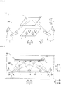
FIG. 2 is a perspective view (schematic view) of a light-source device and a display of the liquid-crystal display device according to the first embodiment of the present invention. -
FIG. 3 is a cross-sectional view (schematic view) at line 700-700 inFIG. 1 . -
FIG. 4 is a plan view (schematic view) of a first light source of the liquid-crystal display device according to the first to third embodiments of the present invention. -
FIG. 5 is a plan view (schematic view) of the light-source device and the display of the liquid-crystal display device according to the first embodiment of the present invention. -
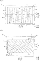
FIGS. 6(a)-6(b) are diagrams for describing an irradiation region of a light of a liquid-crystal display device according to a comparative example. -
FIGS. 7(a)-7(b) are diagrams for describing an irradiation region of a light of the liquid-crystal display device according to the first embodiment of the present invention. -
FIG. 8 is a perspective view (schematic view) of a light-source device and the display of a liquid-crystal display device according to the second embodiment of the present invention. -
FIG. 9 is a perspective view (schematic view) of a light-source device and the display of a liquid-crystal display device according to third embodiment of the present invention. -
FIG. 10 is a plan view (schematic view) of a light-source device and the display of a liquid-crystal display device according to a first modified example of the first embodiment of the present invention. -
FIG. 11 is a plan view (schematic view) of a light-source device and the display of a liquid-crystal display device according to a second modified example of the first embodiment of the present invention. -
FIG. 12 is a plan view (schematic view) of a light-source device and the display of a liquid-crystal display device according to a third modified example of the first embodiment of the present invention. -
FIG. 13 is a perspective view (schematic view) of a light-source device and a display of a liquid-crystal display device according to a modified example of the third embodiment of the present invention. - Embodiments of the present invention will be described in detail below with reference to the drawings. In the following description of embodiments of the invention, numerous specific details are set forth in order to provide a more thorough understanding of the invention. However, it will be apparent to one of ordinary skill in the art that the invention may be practiced without these specific details. In other instances, well-known features have not been described in detail to avoid obscuring the invention.
- First, a liquid-
crystal display device 100 and a light-source device 200 according to a first embodiment of the present invention are described with reference toFIGS. 1 to 7(b) .FIGS. 2 to 7(b) are schematic views; for simplification, illustration is omitted for members unnecessary in the description. - As illustrated in
FIG. 1 , the liquid-crystal display device 100 includes adisplay cell 1 that includes adisplay face 1a. Thedisplay cell 1 has a substantially rectangular shape. Moreover, the liquid-crystal display device 100 includes a front cabinet (front-side housing) 2 and a rear cabinet (rear-side housing) 3 that house thedisplay cell 1. Thedisplay cell 1 is one example of "display." - As illustrated in
FIG. 2 , the liquid-crystal display device 100 (light-source device 200) includes a plurality ofLED light sources 4 and alaser light sources 5a. Moreover, the liquid-crystal display device 100 includes areflective sheet 6 that reflects a light radiated from the LEDlight source 4 to a display-cell 1 side (Y1-direction side). Various optical sheets are provided between thedisplay cell 1 and thereflective sheet 6 but are not illustrated for the sake of simplification. The LEDlight source 4 and thelaser light source 5a are respectively one example of "first light source" and one example of "second light source." - In the first embodiment of the present invention, each of the plurality of
LED light sources 4 is a direct light source disposed so as to oppose thedisplay cell 1. That is, the plurality ofLED light sources 4 emits the lights to aface 1b on an opposite side of thedisplay face 1a of thedisplay cell 1. - For example, the
LED light sources 4 are disposed in a matrix (seeFIG. 4 ). Each of the plurality ofLED light sources 4 is disposed on thereflective sheet 6. A configuration may be such that a plurality of holes is provided in thereflective sheet 6 and each of the plurality ofLED light sources 4 is exposed to the display-cell 1 side (Y1-direction side) via the plurality of holes. - The liquid-
crystal display device 100 is configured so local dimming control is possible by independently controlling each of the plurality ofLED light sources 4. - In the first embodiment of the present invention, as illustrated in
FIG. 2 , the liquid-crystal display device 100 (light-source device 200) includes ascanning mirror unit 5b that scans a light emitted from thelaser light source 5a on theface 1b (for example, a MEMS [microelectromechanical system] mirror, a polygon mirror, a galvano mirror, or the like). For example, onelaser light source 5a and onescanning mirror unit 5b are configured as a pair. That is, the liquid-crystal display device 100 includes a scanning laser light-source unit 5 that includes one pair of thelaser light source 5a and thescanning mirror unit 5b. The scanning laser light-source unit 5 includes an optical system that is not illustrated in addition to thelaser light source 5a and thescanning mirror unit 5b. Thescanning mirror unit 5b and the scanning laser light-source unit 5 are respectively one example of "scanner" and one example of "scanning light-source unit" in one or more embodiments of the present invention. - In the first embodiment of the present invention, a plurality of scanning laser light-
source units 5 is provided (in the first embodiment, two are provided). For example, the plurality of scanning laser light-source units 5 is provided in substantially identical height positions in a Y direction. - In the first embodiment of the present invention, as illustrated in
FIG. 3 , thelaser light source 5a is scanned so the light thereof overlaps the light emitted from the LEDlight source 4 in a predetermined region in a region whereto the light is being irradiated by the LEDlight source 4. For example, thelaser light source 5a scans an entire range of thedisplay cell 1 by thescanning mirror unit 5b. That is, each of the twolaser light sources 5a scans half of the entire range of the display cell 1 (seeFIG. 5 ). While inFIG. 3 thelaser light source 5a is disposed on the Y1-direction side and thescanning mirror unit 5b is disposed on a Y2-direction side of the LEDlight source 4, disposition positions are not limited thereto. - Furthermore, the first embodiment of the present invention is configured to overlap the light emitted from the
laser light source 5a on the light emitted from the LEDlight source 4 without changing a light amount of the light emitted from the LEDlight source 4 but while changing a light amount of the light emitted from thelaser light source 5a. For example, the light amount of thelaser light source 5a is increased at a timing where, while scanning thelaser light source 5a, the light emitted from thelaser light source 5a is being irradiated to the predetermined region. Moreover, at a timing where the light emitted from thelaser light source 5a is being irradiated outside the predetermined region, the light amount of the light emitted from thelaser light source 5a is decreased (or made to be zero). The predetermined region is selected by a control unit (not illustrated) of thelaser light source 5a. For example, the control unit may select a region corresponding to anLED light source 4 whose light amount is comparatively large among the plurality ofLED light sources 4. Moreover, the control unit may select one or a plurality of regions. - In the first embodiment of the present invention, as illustrated in
FIG. 5 , viewed from a direction perpendicular to the display cell 1 (Y direction), each of the two scanning laser light-source units 5 is provided near a side of the substantiallyrectangular display cell 1, these sides being an opposing pair. For example, viewed from the direction perpendicular to the display cell 1 (Y direction), each of the two scanning laser light-source units 5 is disposed on an outer side of thedisplay cell 1. For example, viewed from the Y direction, thelaser light source 5a (seeFIG. 2 ) and thescanning mirror unit 5b (seeFIG. 2 ) are each disposed so as to not overlap thedisplay cell 1. Thescanning mirror unit 5b is disposed on the display-cell 1 side relative to thelaser light source 5a paired thereto (seeFIG. 3 ). - In the first embodiment of the present invention, viewed from the direction perpendicular to the display cell 1 (Y direction), the two scanning laser light-
source units 5 are respectively disposed near onelong side 1c among a pair of long sides of thedisplay cell 1 and near the other long side Id among the pair of long sides. For example, the two scanning laser light-source units 5 are respectively disposed in a substantial center of thelong side 1c and a substantial center of thelong side 1d. Moreover, the light emitted from the scanning laser light-source unit 5 near thelong side 1c is scanned in a region on a lower side (Z2-direction side) of thedisplay cell 1, and the light emitted from the scanning laser light-source unit 5 near the long side Id is scanned in a region on an upper side (Z1-direction side) of thedisplay cell 1. The light emitted from the scanning laser light-source unit 5 near thelong side 1c may be scanned in the region on the upper side (Z1-direction side) of thedisplay cell 1 and the light emitted from the scanning laser light-source unit 5 near the long side Id may be scanned in the region on the lower side (Z2-direction side) of thedisplay cell 1. - In the first embodiment of the present invention, the two scanning laser light-
source units 5 are disposed on acommon base 7. For example, thelaser light source 5a and thescanning mirror unit 5b of the scanning laser light-source unit 5 near thelong side 1c and thelaser light source 5a and thescanning mirror unit 5b of the scanning laser light-source unit 5 near thelong side 1d are each disposed on thesame base 7. - In the first embodiment of the present invention, the
base 7 is made of metal. For example, thebase 7 is molded by aluminum, iron, or the like. - As illustrated in
FIG. 6(a) , with a liquid-crystal display device (light-source device) that, as is conventionally the case, is not provided with the scanning laser light-source unit 5 (seeFIG. 3 ), only theLED light source 4 irradiates a light to thedisplay cell 1. In this situation, as illustrated inFIG. 6(b) , control is possible so, by the plurality of (inFIG. 6(a) , three)LED light sources 4, among a plurality of divided regions B in thedisplay cell 1, a brightness in a range of, for example, 3×4 divided regions B (range of diagonal-line portion) is greater than that of another region. - Furthermore, as illustrated in
FIG. 7(a) , with the liquid-crystal display device 100 (light-source device 200) that includes the scanning laser light-source unit 5, the LEDlight source 4 and thelaser light source 5a each irradiate a light to thedisplay cell 1. In this situation, as illustrated inFIG. 7(b) , control is possible so, by the light emitted from thelaser light source 5a overlapping the lights emitted from the plurality of (inFIG. 6(a) , three)LED light sources 4, among the plurality of divided regions B in thedisplay cell 1, a brightness in a range of, for example, 1×2 divided regions B (range of diagonal-line portion) is greater than that of another region. The range of the region where the brightness can be increased is but one example and is not limited thereto. That is, by providing the scanning laser light-source unit 5 (laser light source 5a), it is possible to increase a precision in brightness control. - The first embodiment of the present invention may provide the following advantages.
- The liquid-
crystal display device 100 according to the first embodiment of the present invention includes thedisplay cell 1, the plurality ofLED light sources 4 that emits the light to theface 1b on the opposite side of thedisplay face 1a of thedisplay cell 1, thelaser light source 5a that differs from the LEDlight source 4, and thescanning mirror unit 5b that scans the light emitted from thelaser light source 5a to theface 1b on the opposite side of thedisplay face 1a. By this, a light can be irradiated to the predetermined region of theface 1b on the opposite side of thedisplay face 1a by scanning the light emitted from thelaser light source 5a. As a result, the predetermined region in thedisplay cell 1 can be locally irradiated by the light emitted from thelaser light source 5a without increasing the number ofLED light sources 4. That is, a region where brightness control is possible can be further subdivided without increasing the number ofLED light sources 4. By this, a precision in brightness control can be improved while suppressing an increased component count. - In the first embodiment of the present invention, as above, the liquid-
crystal display device 100 is configured so thelaser light source 5a is scanned so the light thereof overlaps the light emitted from the LEDlight source 4 in the predetermined region in the region whereto the light is being irradiated by the LEDlight source 4. By this, because a light can be overlapped by the light irradiated from thelight source 5a in the predetermined region in the region being irradiated by the LEDlight source 4, a brightness can be increased locally in the region being irradiated by the LEDlight source 4. - In the first embodiment of the present invention, as above, the liquid-
crystal display device 100 is configured so the light emitted from thelaser light source 5a is overlapped on the light emitted from the LEDlight source 4 while changing the light amount of the light emitted from thelaser light source 5a. By this, the brightness of the predetermined region can be readily increased while performing local dimming control by changing the light amount of thelaser light source 5a when scanning the predetermined region. - In the first embodiment of the present invention, as above, the liquid-
crystal display device 100 is configured so the plurality of scanning laser light-source units 5 is provided, each including thelaser light source 5a and thescanning mirror unit 5b. By this, an entire face of theface 1b on the opposite side of thedisplay face 1a can be scanned more quickly compared to a situation of scanning by a single scanning laser light-source unit 5. - In the first embodiment of the present invention, as above, the liquid-
crystal display device 100 is configured so, viewed from the direction perpendicular to thedisplay cell 1, each of the plurality of scanning laser light-source units 5 is provided near a side of the substantiallyrectangular display cell 1, these sides being an opposing pair. By this, the light of the scanning laser light-source unit 5 can be scanned from mutually opposing directions by each of the plurality of scanning laser light-source units 5 being provided near a side of thedisplay cell 1, these sides being an opposing pair. As a result, the scanning laser light-source unit 5 provided to one side among the pair of sides can scan within thedisplay cell 1 on another side (or one side) of the pair of sides relative to a center of thedisplay cell 1 and the scanning laser light-source unit 5 provided to the other side among the pair of sides can scan within thedisplay cell 1 on the one side (or the other side) of the pair of sides relative to the center of thedisplay cell 1. By this, an excessive burden being applied on one of the plurality of scanning laser light-source units 5 can be suppressed because sizes of the regions respectively scanned by the plurality of scanning laser light-source units 5 can be made substantially identical. - In the first embodiment of the present invention, as above, the liquid-
crystal display device 100 is configured so, viewed from the direction perpendicular to thedisplay cell 1, each of the plurality of scanning laser light-source units 5 is disposed near a side of thedisplay cell 1, these sides being an opposing pair, and on the outer side of thedisplay cell 1. By this, the light from the LEDlight source 4 being blocked by the plurality of scanning laser light-source units 5 can be further suppressed. - In the first embodiment of the present invention, as above, the liquid-
crystal display device 100 is configured so provided are two scanning laser light-source units 5 and, viewed from the direction perpendicular to thedisplay cell 1, the two scanning laser light-source units 5 are respectively disposed near the onelong side 1c among the pair of long sides of thedisplay cell 1 and near the otherlong side 1d among the pair of long sides. By this, a device outer shape of the liquid-crystal display device 100 becoming large in a direction wherein the long sides of thedisplay cell 1 extend can be suppressed by the two scanning laser light-source units 5 being respectively disposed near the onelong side 1c among the pair of long sides of thedisplay cell 1 and near the otherlong side 1d among the pair of long sides. - In the first embodiment of the present invention, as above, the liquid-
crystal display device 100 is configured so the two scanning laser light-source units 5 are respectively disposed in the substantial center of the onelong side 1c among the pair of long sides and in the substantial center of the other long side Id among the pair of long sides. By this, thescanning mirror unit 5b can be readily controlled because scanning angles of thescanning mirror units 5b on the one side and the other side in the two scanning laser light-source units 5 become substantially equal (substantially symmetrical). - In the first embodiment of the present invention, as above, the liquid-
crystal display device 100 is configured so the two scanning laser light-source units 5 are disposed on thesame base 7. By this, an operation efficiency in installing the scanning laser light-source units 5 can be improved because two scanning laser light-source units 5 can be installed simultaneously by installing thebase 7 whereon the two scanning laser light-source units 5 are disposed. Moreover, compared to a situation of installing the two scanning laser light-source units 5 separately, a shift in installation position between the two scanning laser light-source units 5 can be suppressed from arising. - In the first embodiment of the present invention, as above, the liquid-
crystal display device 100 is configured so thebase 7 includes a base made of metal. By this, heat dissipation of the scanning laser light-source unit 5 can be readily performed. - In the first embodiment of the present invention, as above, the liquid-
crystal display device 100 is configured to use theLED light source 4 as the direct light source and thelaser light source 5a as the light source that is scanned. Here, the light emitted from the laser light source has a comparatively higher directionality than the light emitted from the LED light source. Therefore, by scanning by thelaser light source 5a, a precision of brightness control can be readily increased. - The light-
source device 200 according to the first embodiment of the present invention includes the plurality ofLED light sources 4, thelaser light source 5a that differs from the LEDlight source 4, and thescanning mirror unit 5b that scans the light emitted from thelaser light source 5a. By this, the light emitted from thelaser light source 5a can be scanned in the predetermined region. As a result, the predetermined region can be locally irradiated by the light emitted from thelaser light source 5a without increasing the number ofLED light sources 4. By this, a precision in brightness control can be improved while suppressing an increased component count. - Next, configurations of a liquid-
crystal display device 300 and a light-source device 400 according to a second embodiment of the present invention are described with reference toFIG. 8 . This liquid-crystal display device 300 in the second embodiment of the present invention differs from the first embodiment of the present invention, where the light emitted from the scanning laser light-source unit 5 directly irradiates thedisplay cell 1, and a light emitted from a scanning laser light-source unit 15 is irradiated to thedisplay cell 1 upon being reflected by areflective portion 8.FIG. 8 is a schematic view; for simplification, illustration is omitted for members unnecessary in the description. - As illustrated in
FIG. 8 , the liquid-crystal display device 300 (light-source device 400) includes two scanning laser light-source units 15. Moreover, the liquid-crystal display device 300 includes areflective sheet 16 that reflects the light radiated from the LEDlight source 4 to the display-cell 1 side (Y1-direction side). The scanning laser light-source unit 15 is of a configuration similar to the scanning laser light-source unit 5 according to the first embodiment of the present invention and is disposed in a position similar to the scanning laser light-source unit 5. The scanning laser light-source unit 15 is one example of "scanning light-source unit" in one or more embodiments of the present invention. - In the second embodiment of the present invention, the liquid-
crystal display device 300, viewed from the direction perpendicular to the display cell 1 (Y direction), includes thereflective portion 8, which is provided along an outer periphery of thedisplay cell 1. Thereflective portion 8 reflects the light emitted from thelaser light source 5a, which is included in the scanning laser light-source unit 15, to theface 1b on the opposite side of thedisplay face 1a. For example, provided is a plurality of reflective portions 8 (in the second embodiment of the present invention, two are provided). Moreover, viewed from the direction perpendicular to the display cell 1 (Y direction), the tworeflective portions 8 are respectively provided so as to be along ashort side 1e and ashort side 1f of the substantiallyrectangular display cell 1, these sides being an opposing pair. - In the second embodiment of the present invention, the
reflective portion 8 is formed by a vicinity of an outer peripheral edge of thereflective sheet 16 being bent to the display-cell 1 side (Y1-direction side). That is, thereflective sheet 16 and thereflective portion 8 are formed integrally by the same member. Moreover, viewed from the direction perpendicular to the display cell 1 (Y direction), the tworeflective portions 8 are respectively disposed near theshort side 1e and near theshort side 1f. - For example, each of the two
reflective portions 8 is bent in a direction that intersects a plane (XZ plane) whereon thedisplay cell 1 extends. For example, viewed from a Z direction, an angle between thedisplay cell 1 and thereflective portion 8 is about 90 degrees. The angle between thedisplay cell 1 and thereflective portion 8 may be an angle other than 90 degrees. Moreover, thereflective portion 8 per se may have a bent shape or a curved shape. - Other configurations of the second embodiment of the present invention are similar to those of the first embodiment of the present invention.
- The second embodiment of the present invention may provide the following advantages.
- The liquid-
crystal display device 300 according to the second embodiment of the present invention includes thereflective portion 8 that is provided along the outer periphery of thedisplay cell 1 and reflects the light emitted from thelaser light source 5a to theface 1b on the opposite side of thedisplay face 1a. By this, a light can be irradiated to theface 1b on the opposite side of thedisplay face 1a while suppressing light leakage to an outer-peripheral side of thedisplay cell 1 by the light emitted from thelaser light source 5a being reflected by thereflective portion 8 provided along the outer periphery of thedisplay cell 1. - In the liquid-
crystal display device 300 according to the second embodiment of the present invention, thereflective portion 8 is formed by the vicinity of the outer peripheral edge of thereflective sheet 16 being bent to the display-cell 1 side. By this, an increased component count can be suppressed because thereflective portion 8 can be formed using thereflective sheet 16 that is already provided. - Other advantages of the second embodiment of the present invention are similar to those of the first embodiment of the present invention.
- Next, configurations of a liquid-
crystal display device 500 and a light-source device 600 according to a third embodiment of the present invention are described with reference toFIG. 9 . This liquid-crystal display device 500 in the third embodiment of the present invention differs from the first embodiment of the present invention, where the light emitted from the scanning laser light-source unit 5 directly irradiates thedisplay cell 1, and a light emitted from a scanning laser light-source unit 25 is irradiated to thedisplay cell 1 via alight guide plate 9.FIG. 9 is a schematic view; for simplification, illustration is omitted for members unnecessary in the description. - As illustrated in
FIG. 9 , the liquid-crystal display device 500 (light-source device 600) includes a single scanning laser light-source unit 25. The scanning laser light-source unit 25, viewed from the direction perpendicular to the display cell 1 (Y direction), is provided near thelong side 1c of the substantiallyrectangular display cell 1 and on the outer side. Moreover, viewed from the direction perpendicular to the display cell 1 (Y direction), the scanning laser light-source unit 25 is disposed in the substantial center of thelong side 1c. The scanning laser light-source unit 25 is of a configuration similar to the scanning laser light-source unit 5 of the first embodiment of the present invention. The scanning laser light-source unit 25 is one example of "scanning light-source unit" in one or more embodiments of the present invention. - In the third embodiment of the present invention, the liquid-
crystal display device 500 includes thelight guide plate 9, which is provided between thedisplay cell 1 and the LEDlight source 4. Thelight guide plate 9 orients the light emitted from thelaser light source 5a to the display-cell 1 side. For example, thelight guide plate 9 is provided so as to oppose thedisplay cell 1. Moreover, the scanning laser light-source unit 25 is provided on a Z1-direction side of thelight guide plate 9. Thelight guide plate 9 and the scanning laser light-source unit 25 are disposed in substantially identical height positions in the Y direction. For example, the light emitted from the scanning laser light-source unit 25 enters thelight guide plate 9 from the Z1-direction side and, upon passing through thelight guide plate 9, is irradiated to the predetermined region of thedisplay cell 1. Thelight guide plate 9 is one example of "light guide member" in one or more embodiments of the present invention. - Other configurations of the third embodiment of the present invention are similar to those of the first embodiment of the present invention.
- The third embodiment of the present invention may provide the following advantages.
- In the third embodiment of the present invention, the liquid-
crystal display device 500 is configured so as to be provided with thelight guide plate 9 that is provided between thedisplay cell 1 and the LEDlight source 4 and orients the light emitted from thelaser light source 5a to the display-cell 1 side. By this, the light emitted from thelaser light source 5a can be readily irradiated to a region comparatively separated from thelaser light source 5a by thelight guide plate 9. - Other advantages of the third embodiment of the present invention are similar to those of the first embodiment of the present invention.
- One or more embodiments of the present invention disclosed here are examples on all counts and should be considered non-limiting. The scope of the present invention is indicated not by the description of one or more embodiments of the present invention but by the scope of patent claims and further includes meanings equivalent to the scope of patent claims and all modifications (modified examples) within the scope.
- For example, in the first embodiment of the present invention, an example is illustrated where two scanning light-source units (scanning laser light-source units 5) are respectively disposed near a pair of long sides (
long side 1c andlong side 1d), but the present invention is not limited thereto. For example, as illustrated inFIG. 10 , with a liquid-crystal display device 101 (light-source device 201), two scanning light-source units (scanning laser light-source units 5) are respectively disposed near theshort side 1e and near theshort side 1f. In the second embodiment of the present invention as well, similarly, two scanning light-source units (scanning laser light-source units 15) may be respectively disposed near theshort side 1e and near theshort side 1f. In the third embodiment of the present invention, similarly, a scanning light-source unit (scanning laser light-source unit 25) may be disposed near another (long side 1d) among a pair of long sides, near theshort side 1e, or near theshort side 1f.FIG. 10 is a schematic view; for simplification, illustration is omitted for members unnecessary in the description. - In the first embodiment of the present invention, an example is illustrated where two scanning light-source units (scanning laser light-source units 5) are respectively disposed in substantial centers of a pair of long sides (substantial center of
long side 1c and substantial center of long side Id), but the present invention is not limited thereto. For example, as illustrated inFIG. 11 , with a liquid-crystal display device 102 (light-source device 202), two scanning light-source units (scanning laser light-source units 5) are respectively disposed at end portions of a pair of long sides (end portion oflong side 1c and end portion oflong side 1d). In the second embodiment of the present invention as well, similarly, two scanning light-source units (scanning laser light-source units 15) may be respectively disposed near end portions of a pair of long sides (end portion oflong side 1c and end portion oflong side 1d). In the third embodiment of the present invention, similarly, the scanning laser light-source unit 25 may be disposed at an end portion of another (long side 1d) among a pair of long sides, an end portion of theshort side 1e, or an end portion of theshort side 1f.FIG. 11 is a schematic view; for simplification, illustration is omitted for members unnecessary in the description. - In the first embodiment of the present invention, an example is illustrated where two scanning light-source units (scanning laser light-source units 5) are respectively disposed near a pair of long sides (near the
long side 1c and near the long side Id), but the present invention is not limited thereto. For example, as illustrated inFIG. 12 , with a liquid-crystal display device 103 (light-source device 203), one set of two among four scanning light-source units (scanning laser light-source units 5) is disposed near one side (long side 1c) among a pair of long sides and the other set of two among the four scanning light-source units (scanning laser light-source units 5) is disposed near the other side (long side 1d) among the pair of long sides. In this situation, the two scanning light-source units (scanning laser light-source units 5) provided opposing each other are respectively disposed oncommon bases 7. Moreover, by the two scanning light-source units (scanning laser light-source units 5) on an X1-direction side, a half face on an X1-direction side of a display (display cell 1) is scanned and by the two scanning light-source units (scanning laser light-source units 5) on an X2-direction side, a half face on an X2-direction side of the display (display cell 1) is scanned. The two scanning light-source units (scanning laser light-source units 5) near thelong side 1c and the two scanning light-source units (scanning laser light-source units 5) near the long side Id may be respectively disposed oncommon bases 7 or the four scanning light-source units (scanning laser light-source units 5) may be disposed on acommon base 7.FIG. 12 is a schematic view; for simplification, illustration is omitted for members unnecessary in the description. - In the second embodiment of the present invention as well, similarly, one set of two among four scanning light-source units (scanning laser light-source units 15) may be disposed near one side (
long side 1c) among a pair of long sides and the other set of two among the four scanning light-source units (scanning laser light-source units 15) may be disposed near the other side (long side 1d) among the pair of long sides. In the third embodiment of the present invention as well, two scanning light-source units (scanning laser light-source units 25) may be disposed near another side (long side 1d) among a pair of long sides, near theshort side 1e, or near theshort side 1f. - In the third embodiment of the present invention, an example is illustrated where a single light guide member (light guide plate 9) is provided, but the present invention is not limited thereto. For example, as illustrated in
FIG. 13 , with a liquid-crystal display device 501 (light-source device 601), provided is a light guide member (light guide plate 19) divided into three. In this situation, a scanning light-source unit (scanning laser light-source unit 25) is provided on a Z1-direction side of each light guide member (light guide plate 19). A configuration may be such that the light guide member divided into three (light guide plate 19) is only provided with a single scanning light-source unit (scanning laser light-source unit 25).FIG. 13 is a schematic view; for simplification, illustration is omitted for members unnecessary in the description. Thelight guide plate 19 is one example of "light guide member" in one or more embodiments of the present invention. - In the second embodiment of the present invention, an example is illustrated where the
reflective portion 8 is formed by the vicinity of the outer peripheral edge of thereflective sheet 16 being bent to a display-unit (display-cell 1) side, but the present invention is not limited thereto. For example, by providing a separate member such as a reflective mirror, a light emitted from a scanning light-source unit (scanning laser light-source unit 15) may be reflected. - In the second embodiment of the present invention, an example is illustrated where, viewed from a direction perpendicular to a display (display cell 1) (Y direction), two
reflective portions 8 are respectively provided so as to be along ashort side 1e and ashort side 1f of a substantially rectangular display (display cell 1), these sides being an opposing pair, but the present invention is not limited thereto. For example, viewed from the direction perpendicular to the display (display cell 1), thereflective portion 8 may be provided so as to be along all four sides of the display (display cell 1). - In the first to third embodiments of the present invention, examples are illustrated where one second light source (
laser light source 5a) and one scanner (scanning mirror unit 5b) are configured as a pair, but the present invention is not limited thereto. For example, in one scanning light-source unit (scanning laser light-source unit 5 [15, 25]), a plurality may be provided of at least one from among the second light source (laser light source 5a) and the scanner (scanning mirror unit 5b). - In the first to third embodiments of the present invention, examples are illustrated where a scanner (
scanning mirror unit 5b) is disposed on a display-unit (display-cell 1) side of a second light source (laser light source 5a) with which it is paired, but the present invention is not limited thereto. For example, the second light source (laser light source 5a) may be disposed on the display-unit (display-cell 1) side of the scanner (scanning mirror unit 5b) with which it is paired. - In the first to third embodiments of the present invention, examples are illustrated where, viewed from a direction perpendicular to a display (display cell 1) (Y direction), a scanning light-source unit (scanning laser light-source unit 5 [15, 25]) is disposed on an outer side of the display (display cell 1), but the present invention is not limited thereto. For example, viewed from the direction perpendicular to the display (display cell 1) (Y direction), the scanning light-source unit (scanning laser light-source unit 5 [15, 25]) may be disposed so as to overlap the display (display cell 1).
- In the first to third embodiments of the present invention, examples are illustrated where a second light source is a laser light source, but the present invention is not limited thereto. For example, the second light source may be an LED light source.
- In the first to third embodiments of the present invention, examples are illustrated where first light sources (LED light sources 4) are disposed in a matrix, but the present invention is not limited thereto. For example, the first light sources (LED light sources 4) may be disposed in a line.
- In the first and second embodiments of the present invention, examples are illustrated where two scanning light-source units (scanning laser light-source units 5 [15]) are provided in substantially identical height positions in a Y direction, but the present invention is not limited thereto. For example, two scanning light-source units (scanning laser light-source units 5 [15]) may be provided in mutually different height positions in the Y direction.
- In the second embodiment of the present invention, an example is illustrated of a configuration provided with the
reflective portion 8, but the present invention is not limited thereto. For example, a configuration may be one where thereflective portion 8 and a light guide member of the third embodiment of the present invention (light guide plate 9 [19]) are combined. - Although the disclosure has been described with respect to only a limited number of embodiments, those skilled in the art, having benefit of this disclosure, will appreciate that various other embodiments may be devised without departing from the scope of the present invention. Accordingly, the scope of the invention should be limited only by the attached claims.
- 1 Display cell (display)
- 1a Display face
- 1b Face
- 4 LED light source (first light source)
- 5, 15, 25 Scanning laser light-source unit (scanning light-source unit)
- 5a Laser light source (second light source)
- 5b Scanning mirror unit (scanner)
- 6, 16 Reflective sheet
- 7 Base
- 8 Reflective portion
- 9, 19 Light guide plate (light guide member)
- 100, 101, 102, 103, 300, 500, 501 Liquid-crystal display device
- 200, 201, 202, 203, 400, 600, 601 Light-source device
Claims (11)
- A liquid-crystal display device, comprising:a display (1) that comprises a display face (1a);a plurality of first light sources (4), each of which emits a first light to a face (1b) on an opposite side of the display face (1a);a second light source (5a) that differs from the first light source (4) and emits a second light; anda scanner (5b) that scans the second light in the face (1b).
- The liquid-crystal display device according to claim 1,wherein the scanner (5b) scans the second light in a predetermined region within a region to which the first light is irradiated, andwherein the second light overlaps the first lights in the predetermined region.
- The liquid-crystal display device according to claim 2, wherein the second light source (5a) causes a light amount of the second light to be changed and causes the second light to be overlapped on the first light.
- The liquid-crystal display device according to any of claims 1 to 3, further comprising:a plurality of scanning light-source units (5, 15, 25),wherein each of the plurality of scanning light-source units comprises the second light source (5a) and the scanner (5b).
- The liquid-crystal display device according to claim 4,wherein the display (1) has a substantially rectangular shape,wherein viewed from a direction perpendicular to the display, the plurality of scanning light-source units (5, 15) is provided near a pair of sides of the rectangular shape, respectively, andwherein the pair of sides is an opposing pair.
- The liquid-crystal display device according to claim 4 or 5, wherein the plurality of scanning light-source units is disposed on a common base (7).
- The liquid-crystal display device according to any of claims 1 to 6, further comprising:a reflective portion (8) that, viewed from a direction perpendicular to the display face, is provided along an outer periphery of the display face (1),wherein the reflective portion reflects the second light to the face (1b).
- The liquid-crystal display device according to claim 7, further comprising:a reflective sheet (16) that reflects the first light to a display side,wherein the reflective portion (8) is formed by a vicinity of an outer peripheral edge of the reflective sheet bent to the display side.
- The liquid-crystal display device according to any of claims 1 to 8, further comprising:a light guide member (9, 19) that is provided between the display and the first light source,wherein the light guide member orients the second light to a display side.
- The liquid-crystal display device according to any of claims 1 to 9,wherein the first light source (4) comprises a direct Light Emitting Diode (LED) light source disposed to oppose the display (1), andwherein the second light source (5a) comprises a laser light source.
- A light-source device, comprising:a plurality of first light sources (4);a second light source (5a) that differs from the first light source; anda scanner (5b) that scans a light emitted from the second light source.
Applications Claiming Priority (1)
| Application Number | Priority Date | Filing Date | Title |
|---|---|---|---|
| JP2017100888A JP6943016B2 (en) | 2017-05-22 | 2017-05-22 | Liquid crystal display and light source |
Publications (2)
| Publication Number | Publication Date |
|---|---|
| EP3407126A1 true EP3407126A1 (en) | 2018-11-28 |
| EP3407126B1 EP3407126B1 (en) | 2021-06-09 |
Family
ID=62217784
Family Applications (1)
| Application Number | Title | Priority Date | Filing Date |
|---|---|---|---|
| EP18173086.2A Active EP3407126B1 (en) | 2017-05-22 | 2018-05-18 | Liquid-crystal display device |
Country Status (4)
| Country | Link |
|---|---|
| US (1) | US10948771B2 (en) |
| EP (1) | EP3407126B1 (en) |
| JP (1) | JP6943016B2 (en) |
| CN (1) | CN108931868A (en) |
Families Citing this family (1)
| Publication number | Priority date | Publication date | Assignee | Title |
|---|---|---|---|---|
| CN108776406B (en) * | 2018-05-29 | 2021-06-01 | 武汉华星光电技术有限公司 | Preparation substrate of color filter and manufacturing method of color filter substrate |
Citations (4)
| Publication number | Priority date | Publication date | Assignee | Title |
|---|---|---|---|---|
| WO2012032979A1 (en) * | 2010-09-06 | 2012-03-15 | シャープ株式会社 | Lighting device and display device |
| US20140354917A1 (en) * | 2013-05-28 | 2014-12-04 | Hon Hai Precision Industry Co., Ltd. | Liquid crystal display device having laser light source unit and backlight module of same |
| US20160054517A1 (en) * | 2014-08-20 | 2016-02-25 | Mitsubishi Electric Corporation | Surface light source device and liquid crystal display device |
| JP2016035908A (en) | 2014-08-01 | 2016-03-17 | キヤノン株式会社 | Light source device |
Family Cites Families (11)
| Publication number | Priority date | Publication date | Assignee | Title |
|---|---|---|---|---|
| GB2209422B (en) * | 1987-09-03 | 1991-05-29 | Emi Plc Thorn | Displays |
| TWI258044B (en) * | 2005-06-01 | 2006-07-11 | Au Optronics Corp | Direct-type backlight unit structure |
| US20100165013A1 (en) * | 2006-02-09 | 2010-07-01 | Kazuhisa Yamamoto | Liquid crystal display device |
| JP2007219263A (en) * | 2006-02-17 | 2007-08-30 | Mitsubishi Electric Corp | Illumination method and image display apparatus using the method |
| US8317386B2 (en) * | 2006-07-24 | 2012-11-27 | Panasonic Corporation | Laser-lit planar illumination device and LCD using such device |
| US20110001804A1 (en) * | 2008-05-06 | 2011-01-06 | Microvision, Inc. | Apparatus for Displaying 3D Images |
| JP5418969B2 (en) * | 2009-08-10 | 2014-02-19 | 東芝ライテック株式会社 | Light emitting device and image display system |
| JP5368577B2 (en) * | 2009-10-19 | 2013-12-18 | パイオニア株式会社 | Coordinate position detection device, method thereof, and display device |
| US20130135255A1 (en) * | 2011-11-30 | 2013-05-30 | Qualcomm Mems Technologies, Inc. | Display systems including optical touchscreen |
| JP2015141751A (en) * | 2014-01-27 | 2015-08-03 | 株式会社エンプラス | Surface light source device and display device using the same |
| CN106681050A (en) * | 2015-11-06 | 2017-05-17 | 苏州璨宇光学有限公司 | Display device and light source module |
-
2017
- 2017-05-22 JP JP2017100888A patent/JP6943016B2/en not_active Expired - Fee Related
-
2018
- 2018-05-18 EP EP18173086.2A patent/EP3407126B1/en active Active
- 2018-05-18 CN CN201810480523.9A patent/CN108931868A/en active Pending
- 2018-05-21 US US15/984,861 patent/US10948771B2/en not_active Expired - Fee Related
Patent Citations (4)
| Publication number | Priority date | Publication date | Assignee | Title |
|---|---|---|---|---|
| WO2012032979A1 (en) * | 2010-09-06 | 2012-03-15 | シャープ株式会社 | Lighting device and display device |
| US20140354917A1 (en) * | 2013-05-28 | 2014-12-04 | Hon Hai Precision Industry Co., Ltd. | Liquid crystal display device having laser light source unit and backlight module of same |
| JP2016035908A (en) | 2014-08-01 | 2016-03-17 | キヤノン株式会社 | Light source device |
| US20160054517A1 (en) * | 2014-08-20 | 2016-02-25 | Mitsubishi Electric Corporation | Surface light source device and liquid crystal display device |
Also Published As
| Publication number | Publication date |
|---|---|
| CN108931868A (en) | 2018-12-04 |
| JP6943016B2 (en) | 2021-09-29 |
| US10948771B2 (en) | 2021-03-16 |
| US20180335669A1 (en) | 2018-11-22 |
| EP3407126B1 (en) | 2021-06-09 |
| JP2018194786A (en) | 2018-12-06 |
Similar Documents
| Publication | Publication Date | Title |
|---|---|---|
| EP3318793B1 (en) | Backlight device and liquid crystal display device | |
| EP3318792B1 (en) | Backlight device and liquid-crystal display device | |
| JP6906968B2 (en) | Lighting device | |
| US8721130B2 (en) | Vehicle headlamp with cut-off line forming reflector | |
| US20060146530A1 (en) | Led backlight apparatus | |
| US20110304798A1 (en) | Illumination device and liquid crystal display device | |
| WO2013038802A1 (en) | Surface light emitting device and liquid crystal display device provided with same | |
| EP2360502B1 (en) | Backlight unit and display device | |
| TWI596409B (en) | Backlight module | |
| US11067851B2 (en) | Light-emitting apparatus and display apparatus | |
| EP3407126B1 (en) | Liquid-crystal display device | |
| JP2007073295A (en) | Direct backlight device and image display device | |
| EP2762959B1 (en) | Display device | |
| US10663643B2 (en) | Display apparatus for displaying specific pattern, has emission structure region containing several emission structure portions in which emission light quantity in incident to predetermined direction is maximum in direction of light source | |
| US20160033106A1 (en) | Light source device | |
| US9310034B2 (en) | Light emitting device for backlight device and method of operating the light emitting device | |
| US8827491B2 (en) | Lighting device | |
| EP2551229A1 (en) | Elevator car interior illumination apparatus | |
| EP3812652A1 (en) | Vehicular lamp | |
| US20190265550A1 (en) | Light-emitting device, backlight device, and liquid crystal display device | |
| JP2011237484A (en) | Liquid crystal module | |
| EP2894394B1 (en) | Lighting device for illumination buildings, facades or walls | |
| KR101330788B1 (en) | Multi block led back light unit | |
| CN106681050A (en) | Display device and light source module | |
| JP2010165557A (en) | Backlight unit and liquid crystal display equipped with this |
Legal Events
| Date | Code | Title | Description |
|---|---|---|---|
| PUAI | Public reference made under article 153(3) epc to a published international application that has entered the european phase |
Free format text: ORIGINAL CODE: 0009012 |
|
| STAA | Information on the status of an ep patent application or granted ep patent |
Free format text: STATUS: THE APPLICATION HAS BEEN PUBLISHED |
|
| AK | Designated contracting states |
Kind code of ref document: A1 Designated state(s): AL AT BE BG CH CY CZ DE DK EE ES FI FR GB GR HR HU IE IS IT LI LT LU LV MC MK MT NL NO PL PT RO RS SE SI SK SM TR |
|
| AX | Request for extension of the european patent |
Extension state: BA ME |
|
| STAA | Information on the status of an ep patent application or granted ep patent |
Free format text: STATUS: REQUEST FOR EXAMINATION WAS MADE |
|
| STAA | Information on the status of an ep patent application or granted ep patent |
Free format text: STATUS: EXAMINATION IS IN PROGRESS |
|
| 17P | Request for examination filed |
Effective date: 20190524 |
|
| RBV | Designated contracting states (corrected) |
Designated state(s): AL AT BE BG CH CY CZ DE DK EE ES FI FR GB GR HR HU IE IS IT LI LT LU LV MC MK MT NL NO PL PT RO RS SE SI SK SM TR |
|
| 17Q | First examination report despatched |
Effective date: 20190624 |
|
| GRAP | Despatch of communication of intention to grant a patent |
Free format text: ORIGINAL CODE: EPIDOSNIGR1 |
|
| STAA | Information on the status of an ep patent application or granted ep patent |
Free format text: STATUS: GRANT OF PATENT IS INTENDED |
|
| INTG | Intention to grant announced |
Effective date: 20201208 |
|
| GRAS | Grant fee paid |
Free format text: ORIGINAL CODE: EPIDOSNIGR3 |
|
| GRAA | (expected) grant |
Free format text: ORIGINAL CODE: 0009210 |
|
| STAA | Information on the status of an ep patent application or granted ep patent |
Free format text: STATUS: THE PATENT HAS BEEN GRANTED |
|
| AK | Designated contracting states |
Kind code of ref document: B1 Designated state(s): AL AT BE BG CH CY CZ DE DK EE ES FI FR GB GR HR HU IE IS IT LI LT LU LV MC MK MT NL NO PL PT RO RS SE SI SK SM TR |
|
| REG | Reference to a national code |
Ref country code: GB Ref legal event code: FG4D |
|
| REG | Reference to a national code |
Ref country code: CH Ref legal event code: EP Ref country code: AT Ref legal event code: REF Ref document number: 1400992 Country of ref document: AT Kind code of ref document: T Effective date: 20210615 |
|
| REG | Reference to a national code |
Ref country code: DE Ref legal event code: R096 Ref document number: 602018018254 Country of ref document: DE |
|
| REG | Reference to a national code |
Ref country code: IE Ref legal event code: FG4D |
|
| REG | Reference to a national code |
Ref country code: LT Ref legal event code: MG9D |
|
| PG25 | Lapsed in a contracting state [announced via postgrant information from national office to epo] |
Ref country code: LT Free format text: LAPSE BECAUSE OF FAILURE TO SUBMIT A TRANSLATION OF THE DESCRIPTION OR TO PAY THE FEE WITHIN THE PRESCRIBED TIME-LIMIT Effective date: 20210609 Ref country code: HR Free format text: LAPSE BECAUSE OF FAILURE TO SUBMIT A TRANSLATION OF THE DESCRIPTION OR TO PAY THE FEE WITHIN THE PRESCRIBED TIME-LIMIT Effective date: 20210609 Ref country code: FI Free format text: LAPSE BECAUSE OF FAILURE TO SUBMIT A TRANSLATION OF THE DESCRIPTION OR TO PAY THE FEE WITHIN THE PRESCRIBED TIME-LIMIT Effective date: 20210609 Ref country code: BG Free format text: LAPSE BECAUSE OF FAILURE TO SUBMIT A TRANSLATION OF THE DESCRIPTION OR TO PAY THE FEE WITHIN THE PRESCRIBED TIME-LIMIT Effective date: 20210909 |
|
| REG | Reference to a national code |
Ref country code: AT Ref legal event code: MK05 Ref document number: 1400992 Country of ref document: AT Kind code of ref document: T Effective date: 20210609 |
|
| REG | Reference to a national code |
Ref country code: NL Ref legal event code: MP Effective date: 20210609 |
|
| PG25 | Lapsed in a contracting state [announced via postgrant information from national office to epo] |
Ref country code: SE Free format text: LAPSE BECAUSE OF FAILURE TO SUBMIT A TRANSLATION OF THE DESCRIPTION OR TO PAY THE FEE WITHIN THE PRESCRIBED TIME-LIMIT Effective date: 20210609 Ref country code: RS Free format text: LAPSE BECAUSE OF FAILURE TO SUBMIT A TRANSLATION OF THE DESCRIPTION OR TO PAY THE FEE WITHIN THE PRESCRIBED TIME-LIMIT Effective date: 20210609 Ref country code: NO Free format text: LAPSE BECAUSE OF FAILURE TO SUBMIT A TRANSLATION OF THE DESCRIPTION OR TO PAY THE FEE WITHIN THE PRESCRIBED TIME-LIMIT Effective date: 20210909 Ref country code: LV Free format text: LAPSE BECAUSE OF FAILURE TO SUBMIT A TRANSLATION OF THE DESCRIPTION OR TO PAY THE FEE WITHIN THE PRESCRIBED TIME-LIMIT Effective date: 20210609 Ref country code: GR Free format text: LAPSE BECAUSE OF FAILURE TO SUBMIT A TRANSLATION OF THE DESCRIPTION OR TO PAY THE FEE WITHIN THE PRESCRIBED TIME-LIMIT Effective date: 20210910 |
|
| PG25 | Lapsed in a contracting state [announced via postgrant information from national office to epo] |
Ref country code: CZ Free format text: LAPSE BECAUSE OF FAILURE TO SUBMIT A TRANSLATION OF THE DESCRIPTION OR TO PAY THE FEE WITHIN THE PRESCRIBED TIME-LIMIT Effective date: 20210609 Ref country code: AT Free format text: LAPSE BECAUSE OF FAILURE TO SUBMIT A TRANSLATION OF THE DESCRIPTION OR TO PAY THE FEE WITHIN THE PRESCRIBED TIME-LIMIT Effective date: 20210609 Ref country code: RO Free format text: LAPSE BECAUSE OF FAILURE TO SUBMIT A TRANSLATION OF THE DESCRIPTION OR TO PAY THE FEE WITHIN THE PRESCRIBED TIME-LIMIT Effective date: 20210609 Ref country code: NL Free format text: LAPSE BECAUSE OF FAILURE TO SUBMIT A TRANSLATION OF THE DESCRIPTION OR TO PAY THE FEE WITHIN THE PRESCRIBED TIME-LIMIT Effective date: 20210609 Ref country code: PT Free format text: LAPSE BECAUSE OF FAILURE TO SUBMIT A TRANSLATION OF THE DESCRIPTION OR TO PAY THE FEE WITHIN THE PRESCRIBED TIME-LIMIT Effective date: 20211011 Ref country code: ES Free format text: LAPSE BECAUSE OF FAILURE TO SUBMIT A TRANSLATION OF THE DESCRIPTION OR TO PAY THE FEE WITHIN THE PRESCRIBED TIME-LIMIT Effective date: 20210609 Ref country code: EE Free format text: LAPSE BECAUSE OF FAILURE TO SUBMIT A TRANSLATION OF THE DESCRIPTION OR TO PAY THE FEE WITHIN THE PRESCRIBED TIME-LIMIT Effective date: 20210609 Ref country code: SM Free format text: LAPSE BECAUSE OF FAILURE TO SUBMIT A TRANSLATION OF THE DESCRIPTION OR TO PAY THE FEE WITHIN THE PRESCRIBED TIME-LIMIT Effective date: 20210609 Ref country code: SK Free format text: LAPSE BECAUSE OF FAILURE TO SUBMIT A TRANSLATION OF THE DESCRIPTION OR TO PAY THE FEE WITHIN THE PRESCRIBED TIME-LIMIT Effective date: 20210609 |
|
| PG25 | Lapsed in a contracting state [announced via postgrant information from national office to epo] |
Ref country code: PL Free format text: LAPSE BECAUSE OF FAILURE TO SUBMIT A TRANSLATION OF THE DESCRIPTION OR TO PAY THE FEE WITHIN THE PRESCRIBED TIME-LIMIT Effective date: 20210609 |
|
| REG | Reference to a national code |
Ref country code: DE Ref legal event code: R097 Ref document number: 602018018254 Country of ref document: DE |
|
| PLBE | No opposition filed within time limit |
Free format text: ORIGINAL CODE: 0009261 |
|
| STAA | Information on the status of an ep patent application or granted ep patent |
Free format text: STATUS: NO OPPOSITION FILED WITHIN TIME LIMIT |
|
| PG25 | Lapsed in a contracting state [announced via postgrant information from national office to epo] |
Ref country code: DK Free format text: LAPSE BECAUSE OF FAILURE TO SUBMIT A TRANSLATION OF THE DESCRIPTION OR TO PAY THE FEE WITHIN THE PRESCRIBED TIME-LIMIT Effective date: 20210609 |
|
| 26N | No opposition filed |
Effective date: 20220310 |
|
| PG25 | Lapsed in a contracting state [announced via postgrant information from national office to epo] |
Ref country code: AL Free format text: LAPSE BECAUSE OF FAILURE TO SUBMIT A TRANSLATION OF THE DESCRIPTION OR TO PAY THE FEE WITHIN THE PRESCRIBED TIME-LIMIT Effective date: 20210609 |
|
| PG25 | Lapsed in a contracting state [announced via postgrant information from national office to epo] |
Ref country code: IT Free format text: LAPSE BECAUSE OF FAILURE TO SUBMIT A TRANSLATION OF THE DESCRIPTION OR TO PAY THE FEE WITHIN THE PRESCRIBED TIME-LIMIT Effective date: 20210609 |
|
| REG | Reference to a national code |
Ref country code: CH Ref legal event code: PL |
|
| REG | Reference to a national code |
Ref country code: BE Ref legal event code: MM Effective date: 20220531 |
|
| GBPC | Gb: european patent ceased through non-payment of renewal fee |
Effective date: 20220518 |
|
| PG25 | Lapsed in a contracting state [announced via postgrant information from national office to epo] |
Ref country code: MC Free format text: LAPSE BECAUSE OF FAILURE TO SUBMIT A TRANSLATION OF THE DESCRIPTION OR TO PAY THE FEE WITHIN THE PRESCRIBED TIME-LIMIT Effective date: 20210609 Ref country code: LU Free format text: LAPSE BECAUSE OF NON-PAYMENT OF DUE FEES Effective date: 20220518 Ref country code: LI Free format text: LAPSE BECAUSE OF NON-PAYMENT OF DUE FEES Effective date: 20220531 Ref country code: CH Free format text: LAPSE BECAUSE OF NON-PAYMENT OF DUE FEES Effective date: 20220531 |
|
| PG25 | Lapsed in a contracting state [announced via postgrant information from national office to epo] |
Ref country code: IE Free format text: LAPSE BECAUSE OF NON-PAYMENT OF DUE FEES Effective date: 20220518 Ref country code: FR Free format text: LAPSE BECAUSE OF NON-PAYMENT OF DUE FEES Effective date: 20220531 |
|
| PG25 | Lapsed in a contracting state [announced via postgrant information from national office to epo] |
Ref country code: GB Free format text: LAPSE BECAUSE OF NON-PAYMENT OF DUE FEES Effective date: 20220518 Ref country code: BE Free format text: LAPSE BECAUSE OF NON-PAYMENT OF DUE FEES Effective date: 20220531 |
|
| PG25 | Lapsed in a contracting state [announced via postgrant information from national office to epo] |
Ref country code: HU Free format text: LAPSE BECAUSE OF FAILURE TO SUBMIT A TRANSLATION OF THE DESCRIPTION OR TO PAY THE FEE WITHIN THE PRESCRIBED TIME-LIMIT; INVALID AB INITIO Effective date: 20180518 |
|
| PG25 | Lapsed in a contracting state [announced via postgrant information from national office to epo] |
Ref country code: MK Free format text: LAPSE BECAUSE OF FAILURE TO SUBMIT A TRANSLATION OF THE DESCRIPTION OR TO PAY THE FEE WITHIN THE PRESCRIBED TIME-LIMIT Effective date: 20210609 Ref country code: CY Free format text: LAPSE BECAUSE OF FAILURE TO SUBMIT A TRANSLATION OF THE DESCRIPTION OR TO PAY THE FEE WITHIN THE PRESCRIBED TIME-LIMIT Effective date: 20210609 |
|
| PG25 | Lapsed in a contracting state [announced via postgrant information from national office to epo] |
Ref country code: TR Free format text: LAPSE BECAUSE OF FAILURE TO SUBMIT A TRANSLATION OF THE DESCRIPTION OR TO PAY THE FEE WITHIN THE PRESCRIBED TIME-LIMIT Effective date: 20210609 |
|
| PGFP | Annual fee paid to national office [announced via postgrant information from national office to epo] |
Ref country code: DE Payment date: 20240328 Year of fee payment: 7 |
|
| PG25 | Lapsed in a contracting state [announced via postgrant information from national office to epo] |
Ref country code: MT Free format text: LAPSE BECAUSE OF FAILURE TO SUBMIT A TRANSLATION OF THE DESCRIPTION OR TO PAY THE FEE WITHIN THE PRESCRIBED TIME-LIMIT Effective date: 20210609 |
|
| REG | Reference to a national code |
Ref country code: DE Ref legal event code: R119 Ref document number: 602018018254 Country of ref document: DE |
|
| PG25 | Lapsed in a contracting state [announced via postgrant information from national office to epo] |
Ref country code: DE Free format text: LAPSE BECAUSE OF NON-PAYMENT OF DUE FEES Effective date: 20251202 |