EP3407123A1 - Viewing angle controlling film, backlight unit using the same and display device using the same - Google Patents
Viewing angle controlling film, backlight unit using the same and display device using the same Download PDFInfo
- Publication number
- EP3407123A1 EP3407123A1 EP18174080.4A EP18174080A EP3407123A1 EP 3407123 A1 EP3407123 A1 EP 3407123A1 EP 18174080 A EP18174080 A EP 18174080A EP 3407123 A1 EP3407123 A1 EP 3407123A1
- Authority
- EP
- European Patent Office
- Prior art keywords
- light
- viewing angle
- angle controlling
- guide plate
- conversion portion
- Prior art date
- Legal status (The legal status is an assumption and is not a legal conclusion. Google has not performed a legal analysis and makes no representation as to the accuracy of the status listed.)
- Granted
Links
Images



Classifications
-
- G—PHYSICS
- G02—OPTICS
- G02F—OPTICAL DEVICES OR ARRANGEMENTS FOR THE CONTROL OF LIGHT BY MODIFICATION OF THE OPTICAL PROPERTIES OF THE MEDIA OF THE ELEMENTS INVOLVED THEREIN; NON-LINEAR OPTICS; FREQUENCY-CHANGING OF LIGHT; OPTICAL LOGIC ELEMENTS; OPTICAL ANALOGUE/DIGITAL CONVERTERS
- G02F1/00—Devices or arrangements for the control of the intensity, colour, phase, polarisation or direction of light arriving from an independent light source, e.g. switching, gating or modulating; Non-linear optics
- G02F1/01—Devices or arrangements for the control of the intensity, colour, phase, polarisation or direction of light arriving from an independent light source, e.g. switching, gating or modulating; Non-linear optics for the control of the intensity, phase, polarisation or colour
- G02F1/13—Devices or arrangements for the control of the intensity, colour, phase, polarisation or direction of light arriving from an independent light source, e.g. switching, gating or modulating; Non-linear optics for the control of the intensity, phase, polarisation or colour based on liquid crystals, e.g. single liquid crystal display cells
- G02F1/1323—Arrangements for providing a switchable viewing angle
-
- G—PHYSICS
- G02—OPTICS
- G02B—OPTICAL ELEMENTS, SYSTEMS OR APPARATUS
- G02B26/00—Optical devices or arrangements for the control of light using movable or deformable optical elements
- G02B26/02—Optical devices or arrangements for the control of light using movable or deformable optical elements for controlling the intensity of light
-
- G—PHYSICS
- G02—OPTICS
- G02B—OPTICAL ELEMENTS, SYSTEMS OR APPARATUS
- G02B26/00—Optical devices or arrangements for the control of light using movable or deformable optical elements
- G02B26/08—Optical devices or arrangements for the control of light using movable or deformable optical elements for controlling the direction of light
-
- G—PHYSICS
- G02—OPTICS
- G02B—OPTICAL ELEMENTS, SYSTEMS OR APPARATUS
- G02B6/00—Light guides; Structural details of arrangements comprising light guides and other optical elements, e.g. couplings
- G02B6/0001—Light guides; Structural details of arrangements comprising light guides and other optical elements, e.g. couplings specially adapted for lighting devices or systems
- G02B6/0011—Light guides; Structural details of arrangements comprising light guides and other optical elements, e.g. couplings specially adapted for lighting devices or systems the light guides being planar or of plate-like form
- G02B6/0033—Means for improving the coupling-out of light from the light guide
- G02B6/0035—Means for improving the coupling-out of light from the light guide provided on the surface of the light guide or in the bulk of it
- G02B6/0036—2-D arrangement of prisms, protrusions, indentations or roughened surfaces
-
- G—PHYSICS
- G02—OPTICS
- G02F—OPTICAL DEVICES OR ARRANGEMENTS FOR THE CONTROL OF LIGHT BY MODIFICATION OF THE OPTICAL PROPERTIES OF THE MEDIA OF THE ELEMENTS INVOLVED THEREIN; NON-LINEAR OPTICS; FREQUENCY-CHANGING OF LIGHT; OPTICAL LOGIC ELEMENTS; OPTICAL ANALOGUE/DIGITAL CONVERTERS
- G02F1/00—Devices or arrangements for the control of the intensity, colour, phase, polarisation or direction of light arriving from an independent light source, e.g. switching, gating or modulating; Non-linear optics
- G02F1/01—Devices or arrangements for the control of the intensity, colour, phase, polarisation or direction of light arriving from an independent light source, e.g. switching, gating or modulating; Non-linear optics for the control of the intensity, phase, polarisation or colour
- G02F1/13—Devices or arrangements for the control of the intensity, colour, phase, polarisation or direction of light arriving from an independent light source, e.g. switching, gating or modulating; Non-linear optics for the control of the intensity, phase, polarisation or colour based on liquid crystals, e.g. single liquid crystal display cells
- G02F1/133—Constructional arrangements; Operation of liquid crystal cells; Circuit arrangements
- G02F1/1333—Constructional arrangements; Manufacturing methods
- G02F1/1335—Structural association of cells with optical devices, e.g. polarisers or reflectors
- G02F1/1336—Illuminating devices
- G02F1/133602—Direct backlight
-
- G—PHYSICS
- G02—OPTICS
- G02F—OPTICAL DEVICES OR ARRANGEMENTS FOR THE CONTROL OF LIGHT BY MODIFICATION OF THE OPTICAL PROPERTIES OF THE MEDIA OF THE ELEMENTS INVOLVED THEREIN; NON-LINEAR OPTICS; FREQUENCY-CHANGING OF LIGHT; OPTICAL LOGIC ELEMENTS; OPTICAL ANALOGUE/DIGITAL CONVERTERS
- G02F1/00—Devices or arrangements for the control of the intensity, colour, phase, polarisation or direction of light arriving from an independent light source, e.g. switching, gating or modulating; Non-linear optics
- G02F1/01—Devices or arrangements for the control of the intensity, colour, phase, polarisation or direction of light arriving from an independent light source, e.g. switching, gating or modulating; Non-linear optics for the control of the intensity, phase, polarisation or colour
- G02F1/13—Devices or arrangements for the control of the intensity, colour, phase, polarisation or direction of light arriving from an independent light source, e.g. switching, gating or modulating; Non-linear optics for the control of the intensity, phase, polarisation or colour based on liquid crystals, e.g. single liquid crystal display cells
- G02F1/133—Constructional arrangements; Operation of liquid crystal cells; Circuit arrangements
- G02F1/1333—Constructional arrangements; Manufacturing methods
- G02F1/1335—Structural association of cells with optical devices, e.g. polarisers or reflectors
- G02F1/1336—Illuminating devices
- G02F1/133602—Direct backlight
- G02F1/133606—Direct backlight including a specially adapted diffusing, scattering or light controlling members
-
- G—PHYSICS
- G02—OPTICS
- G02F—OPTICAL DEVICES OR ARRANGEMENTS FOR THE CONTROL OF LIGHT BY MODIFICATION OF THE OPTICAL PROPERTIES OF THE MEDIA OF THE ELEMENTS INVOLVED THEREIN; NON-LINEAR OPTICS; FREQUENCY-CHANGING OF LIGHT; OPTICAL LOGIC ELEMENTS; OPTICAL ANALOGUE/DIGITAL CONVERTERS
- G02F1/00—Devices or arrangements for the control of the intensity, colour, phase, polarisation or direction of light arriving from an independent light source, e.g. switching, gating or modulating; Non-linear optics
- G02F1/01—Devices or arrangements for the control of the intensity, colour, phase, polarisation or direction of light arriving from an independent light source, e.g. switching, gating or modulating; Non-linear optics for the control of the intensity, phase, polarisation or colour
- G02F1/13—Devices or arrangements for the control of the intensity, colour, phase, polarisation or direction of light arriving from an independent light source, e.g. switching, gating or modulating; Non-linear optics for the control of the intensity, phase, polarisation or colour based on liquid crystals, e.g. single liquid crystal display cells
- G02F1/133—Constructional arrangements; Operation of liquid crystal cells; Circuit arrangements
- G02F1/1333—Constructional arrangements; Manufacturing methods
- G02F1/1335—Structural association of cells with optical devices, e.g. polarisers or reflectors
- G02F1/1336—Illuminating devices
- G02F1/133602—Direct backlight
- G02F1/133606—Direct backlight including a specially adapted diffusing, scattering or light controlling members
- G02F1/133607—Direct backlight including a specially adapted diffusing, scattering or light controlling members the light controlling member including light directing or refracting elements, e.g. prisms or lenses
-
- G—PHYSICS
- G02—OPTICS
- G02F—OPTICAL DEVICES OR ARRANGEMENTS FOR THE CONTROL OF LIGHT BY MODIFICATION OF THE OPTICAL PROPERTIES OF THE MEDIA OF THE ELEMENTS INVOLVED THEREIN; NON-LINEAR OPTICS; FREQUENCY-CHANGING OF LIGHT; OPTICAL LOGIC ELEMENTS; OPTICAL ANALOGUE/DIGITAL CONVERTERS
- G02F1/00—Devices or arrangements for the control of the intensity, colour, phase, polarisation or direction of light arriving from an independent light source, e.g. switching, gating or modulating; Non-linear optics
- G02F1/01—Devices or arrangements for the control of the intensity, colour, phase, polarisation or direction of light arriving from an independent light source, e.g. switching, gating or modulating; Non-linear optics for the control of the intensity, phase, polarisation or colour
- G02F1/13—Devices or arrangements for the control of the intensity, colour, phase, polarisation or direction of light arriving from an independent light source, e.g. switching, gating or modulating; Non-linear optics for the control of the intensity, phase, polarisation or colour based on liquid crystals, e.g. single liquid crystal display cells
- G02F1/133—Constructional arrangements; Operation of liquid crystal cells; Circuit arrangements
- G02F1/1333—Constructional arrangements; Manufacturing methods
- G02F1/1335—Structural association of cells with optical devices, e.g. polarisers or reflectors
- G02F1/1336—Illuminating devices
- G02F1/133626—Illuminating devices providing two modes of illumination, e.g. day-night
-
- G—PHYSICS
- G02—OPTICS
- G02F—OPTICAL DEVICES OR ARRANGEMENTS FOR THE CONTROL OF LIGHT BY MODIFICATION OF THE OPTICAL PROPERTIES OF THE MEDIA OF THE ELEMENTS INVOLVED THEREIN; NON-LINEAR OPTICS; FREQUENCY-CHANGING OF LIGHT; OPTICAL LOGIC ELEMENTS; OPTICAL ANALOGUE/DIGITAL CONVERTERS
- G02F2202/00—Materials and properties
- G02F2202/14—Materials and properties photochromic
Definitions
- the present disclosure relates to a display device, and more particularly, to a display device comprising a viewing angle controlling film.
- a display device comprising a viewing angle controlling device to protect privacy of a user has been devised. That is, a display device which allows only a user to view an image without allowing people near the user to view the image by reducing a viewing angle using the viewing angle controlling device has been devised.
- FIG. 1 is a brief view illustrating a display device comprising a viewing angle controlling device according to the related art.
- the display device of the related art comprises a display panel 10 and a viewing angle controlling film 20.
- the viewing angle controlling film 20 is arranged above the display panel 10 and controls a viewing angle of an image emitted from the display panel 10.
- the viewing angle controlling film 20 is provided with a plurality of barriers 25 made of a light-shielding material therein, the viewing angle for the image emitted from the display panel 10 is reduced. Therefore, the user can view the image only at a front side of the display panel 10, and has a difficulty in viewing the image at a peripheral side of the display panel 10.
- the viewing angle controlling film 20 of the related art is used, the viewing angle of the display device is fixed without being changed, whereby a problem occurs in that the user should always view an image at a narrow viewing angle.
- the viewing angle controlling film 20 may detachably be fixed to the display panel 10. In this case, there is inconvenience that the user should arrange the viewing angle controlling film 20 in person.
- the present disclosure is directed to a viewing angle controlling film and a backlight unit using the same and a display device using the same that substantially obviates one or more problems due to limitations and disadvantages of the related art.
- An advantage of the present disclosure is to provide a viewing angle controlling film and a backlight unit using the same and a display device using the same, in which a viewing angle may easily be changed while the viewing angle controlling film is not detachable to a display panel.
- a viewing angle controlling film comprises a first area where light transmittance is not converted (with a first light transmissivity, optionally a fixed light transmissivity); and a second area where light transmittance is converted (with a fixed light transmissivity), wherein the second area includes a light-transmittance conversion portion configured to react with light of a predetermined wavelength range to convert the light transmittance and not to react with light of a wavelength range other than the predetermined wavelength range. That is to say, the second area includes a light-transmittance conversion portion configured to decrease its transmissivity when exposed to light of the predetermined wavelength range, while the first area may not be configured to decrease its transmissivity when exposed to light of the predetermined wavelength range.
- a backlight unit comprises a first light source for emitting first light of a first wavelength range; a second light source for emitting second light of a second wavelength range different from the first wavelength range; and a viewing angle controlling film, wherein the viewing angle controlling film comprises; a first area where light transmittance is not converted; and a second area where light transmittance is converted, wherein the second area includes a light-transmittance conversion portion configured to react with the second light to convert the light transmittance and not to react with the first light.
- a display device comprises a first light source for emitting first light of a first wavelength range; a second light source for emitting second light of a second wavelength range different from the first wavelength range; a viewing angle controlling film; and a display panel for displaying an image by being supplied with the first light, wherein the viewing angle controlling film comprises; a first area where light transmittance is not converted; and a second area where light transmittance is converted, wherein the second area includes a light-transmittance conversion portion configured to react with the second light to convert the light transmittance and not to react with the first light.
- a display device comprises a display panel for displaying an image; a light source for emitting light of a predetermined wavelength range; and a viewing angle controlling film, wherein the viewing angle controlling film comprises; a first area where light transmittance is not converted; and a second area where light transmittance is converted, wherein the second area includes a light-transmittance conversion portion configured to react with light of the predetermined wavelength range to convert the light transmittance and not to react with light emitted from the display panel.
- the first area may adjoin the second area laterally.
- a third area with another light transmissivity may be further provided.
- the third area may include an opaque area having a light-shielding portion, adjoins the second area, optionally while overlapping the second area vertically, and adjoins the first area laterally.
- one or more portions may be arranged between two other portions unless 'just' or 'direct' is used.
- first, second, etc. may be used herein to describe various elements, these elements should not be limited by these terms. These terms are only used to distinguish one element from another element. For example, a first element could be termed a second element, and, similarly, a second element could be termed a first element, without departing from the scope of the present disclosure.
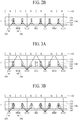
- FIGS. 2a and 2b are brief views illustrating a display device comprising a viewing angle controlling device according to one embodiment of the present disclosure, wherein FIG. 2a corresponds to a wide viewing angle mode, and FIG. 2b corresponds to a narrow viewing angle mode.
- the display device comprises viewing angle controlling devices 100 and 200, a backlight unit light source 300, and a display panel 400.
- the viewing angle controlling devices 100 and 200 include a viewing angle controlling film 100 and a viewing angle controlling light source 200.
- the viewing angle controlling film 100 may include an area where light transmittance is changed by being reversibly reacted with light emitted from the viewing angle controlling light source 200 and an area that is always transparent regardless of light emitted from the viewing angle controlling light source 200, thereby controlling a viewing angle of the display device.
- the viewing angle controlling film 100 includes a base 110, a light-transmittance conversion portion 120, and protective portions 130 and 140.
- the base 110 is made of a transparent material.
- a plurality of grooves 111 are provided in the base 110.
- the plurality of grooves 111 may be formed to pass through an upper surface to a lower surface of the base 110 as shown.
- the plurality of grooves 111 are not limited to the shown example.
- the light-transmittance conversion portion 120 is formed in the plurality of grooves 111 of the base 110.
- the light-transmittance conversion portion 120 is provided with a plurality of partition walls spaced apart from one another at a predetermined interval.
- the viewing angle of the display device can be controlled by light-transmittance change of the light-transmittance conversion portion 120.
- the light-transmittance conversion portion 120 may be filled in, but not limited to, entirety of the plurality of grooves 111.
- the light-transmittance conversion portion 120 includes a material of which light transmittance is reversibly changed due to reaction with light emitted from the viewing angle controlling light source 200. That is, light transmittance of the light-transmittance conversion portion 120 in the case that light is not emitted from the viewing angle controlling light source 200 is different from light transmittance of the light-transmittance conversion portion 120 in the case that light is emitted from the viewing angle controlling light source 200.
- the light-transmittance conversion portion 120 is a transparent state in the case that light is not emitted from the viewing angle controlling light source 200, and if light is emitted from the viewing angle controlling light source 200, the light-transmittance conversion portion 120 may be switched to an opaque state by being reacted with the emitted light.
- This light-transmittance conversion portion 120 may include a material, such as a photochromic material, of which light transmittance is changed due to reversible reaction with light of a specific wavelength.
- a photo-reactive transmittance conversion material the material of which light transmittance is changed by reversible reaction with light of the specific wavelength.
- the photo-reactive transmittance conversion material may be included in the light-transmittance conversion portion 120 in the range of 1 weight % to 20 weight %. If the photo-reactive transmittance conversion material is included in the light-transmittance conversion portion 120 in the range less than 1 weight %, a light-transmittance variation of the light-transmittance conversion portion 120 is not great even though light is emitted from the viewing angle controlling light source 200, whereby a viewing angle controlling function may be deteriorated.
- a photochromic material is included in the light-transmittance conversion portion 120 in the range less than 1 weight %, a light-shielding ratio of the light-transmittance conversion portion 120 is reduced to a value less than 70%, whereby it is noted that the viewing angle controlling function is deteriorated. Also, if the photo-reactive transmittance conversion material exceeds 20 weight % of the light-transmittance conversion portion 120, a light-shielding ratio of the light-transmittance conversion portion 120 is not increased greatly and only a process of forming the light-transmittance conversion portion 120 may be difficult.
- the photochromic material is included in the light-transmittance conversion portion 120 in the range of 20 weight %, the light-shielding ratio of the light-transmittance conversion portion 120 is 90% or more, whereby it is noted that the viewing angle controlling function is sufficient.
- the light-transmittance conversion portion 120 is formed by including a process of dissolving the photo-reactive transmittance conversion material in a polymer resin. At this time, if the photo-reactive transmittance conversion material exceeds 20 weight % of the light-transmittance conversion portion 120, the process of dissolving the photo-reactive transmittance conversion material in the polymer resin may be difficult.
- the protective portions 130 and 140 include an upper protective portion 130 and a lower protective portion 140.
- the upper protective portion 130 is formed on upper surfaces of the base 110 and the light-transmittance conversion portion 120 to protect the upper surfaces of the base 110 and the light-transmittance conversion portion 120.
- the lower protective portion 140 is formed on lower surfaces of the base 110 and the light-transmittance conversion portion 120 to protect the lower surfaces of the base 110 and the light-transmittance conversion portion 120.
- the light-transmittance conversion portion 120 is sealed by the protective portions 130 and 140 to be prevented from leaking out.
- the protective portions 130 and 140 are made of a transparent material.
- the viewing angle controlling light source 200 supplies light to the viewing angle controlling film 100 and changes light transmittance of the light-transmittance conversion portion 120.
- the viewing angle controlling light source 200 may be made of, but not limited to, a point light source such as LED.
- the viewing angle controlling light source 200 emits light of a wavelength different from that of the backlight light source 300.
- the backlight light source 300 may emit light of a visible ray wavelength while the viewing angle controlling light source 200 may emit light of a short wavelength of 400nm or less.
- the light-transmittance conversion portion 120 may include a photo-reactive transmittance conversion material reversibly reacted with light of a short wavelength of 400nm or less.
- the backlight light source 300 serves to supply light to the display panel 400.
- the backlight light source 300 may be made of, but not limited to, a point light source such as LED.
- the backlight light source 300 emits light of a wavelength different from that of the viewing angle controlling light source 200.
- the light emitted from the backlight light source 300 does not change light transmittance of the light-transmittance conversion portion 120.
- the light-transmittance conversion portion 120 is reversibly reacted with light of a short wavelength of 400nm or less emitted from the viewing angle controlling light source 200, whereby its light transmittance is changed.
- the light-transmittance conversion portion 120 is not reacted with light of a visible ray wavelength emitted from the backlight light source 300, whereby its light transmittance is not changed.
- the backlight light source 300 and the viewing angle controlling light source 200 may be arranged below the viewing angle controlling film 100. Various modifications may be made to a detailed arrangement of the backlight light source 300 and the viewing angle controlling light source 200, and will be described later.
- the display panel 400 may be arranged above the viewing angle controlling film 100.
- the display panel 400 may be made of a liquid crystal display panel which is a non-light emission panel, and thus may display an image through light emitted from the backlight light source 300.
- the display panel 400 according to the present disclosure is not limited to the liquid crystal panel.
- the display panel 400 may be made of a self-light emission panel like an organic light emitting panel. In this case, the backlight light source 300 is not required.
- the display panel 400 includes pixels of red (R), green (G) and blue (B).
- a viewing angle controlling method of the display device is as follows.
- the viewing angle controlling light source 200 if the viewing angle controlling light source 200 is maintained at an off-state, the light-transmittance conversion portion 120 becomes a transparent state, whereby the viewing angle controlling film 100 becomes transparent. Therefore, the light emitted from the backlight light source 300 moves toward various directions by transmitting the base 110 and the light-transmittance conversion portion 120, whereby a wide viewing angle mode is realized.
- the viewing angle controlling light source 200 if the viewing angle controlling light source 200 is maintained at an on-state, the light-transmittance conversion portion 120 becomes an opaque state, whereby the viewing angle controlling film 100 includes a transparent area (an area of the base 110) and an opaque area (an area of the light-transmittance conversion portion 120). Therefore, the light emitted from the backlight light source 300 moves to the transparent area only, whereby a narrow viewing angle mode is realized.
- the light-transmittance conversion portion 120 may be provided in such a manner that the light-transmittance conversion portion 120 becomes an opaque state to realize the narrow viewing angle mode when the viewing angle controlling light source 200 is maintained at an off-state, and the light-transmittance conversion portion 120 becomes a transparent state to realize the wide viewing angle mode when the viewing angle controlling light source 200 is maintained at an on-state.
- a moire phenomenon occurs due to a relation between movement of the light and arrangement of the pixels, whereby image quality may be deteriorated. Therefore, to prevent the moire phenomenon from occurring, as shown in portions drawn out of arrows of FIG. 2a , a plurality of beads 150 may be included in the protective portions 130 and 140.
- the beads 150 are provided in the protective portions 130 and 140, the light emitted from the backlight light source 300, moving toward the transparent area only is diffracted or diffused while colliding with the beads 150, whereby the moire phenomenon may be reduced.
- the beads 150 may be included in both the upper protective portion 130 and the lower protective portion 140 but may be included in any one of the upper protective portion 130 and the lower protective portion 140.
- FIGS. 3a and 3b are brief views illustrating a display device comprising a viewing angle controlling device according to another embodiment of the present disclosure, wherein FIG. 3a corresponds to a wide viewing angle mode, and FIG. 3b corresponds to a narrow viewing angle mode.
- FIGS. 3a and 3b are the same as that of FIGS. 2a and 2b except that the viewing angle controlling film 100 is changed. Therefore, the same reference numerals are given to the same elements, and only elements different from those of FIGS. 2a and 2b will be described hereinafter.
- the viewing angle controlling film 100 may include an area of which light transmittance is changed by reversible reaction with light emitted from the viewing angle controlling light source 200, an area always transparent regardless of the light emitted from the viewing angle controlling light source 200, and an area always opaque regardless of the light emitted from the viewing angle controlling light source 200, whereby the viewing angle of the display device may be controlled.
- the viewing angle controlling film 100 includes a base 110, a light-transmittance conversion portion 120, a light-shielding portion 160, and protective portions 130 and 140.
- the base 110 is made of a transparent material in the same manner as the aforementioned embodiment, and includes a plurality of grooves 111.
- the light-transmittance conversion portion 120 is formed in the plurality of grooves 111 of the base 110. Particularly, the light-transmittance conversion portion 120 is formed in a part of each of the plurality of grooves 111, and the light-shielding portion 160 is formed in the other part of each of the plurality of grooves 111. That is, the light-transmittance conversion portion 120 and the light-shielding portion 160 are formed in the plurality of grooves 111 while overlapping and adjoining each other. Since detailed elements of the light-transmittance conversion portion 120 are the same as the aforementioned elements, their repeated description will be omitted.
- the light-shielding portion 160 is formed in the plurality of grooves 111 of the base 110 while overlapping the light-transmittance conversion portion 120 as described above.
- the light-shielding portion 160 includes a light-shielding material, such as carbon black, known in the art. As shown, the light-shielding portion 160 may be arranged below, but not limited to, the light-transmittance conversion portion 120. The light-shielding portion 160 may be arranged above the light-transmittance conversion portion 120.
- the viewing angle controlling film 100 includes the light-shielding portion 160, whereby the narrow viewing angle mode may be more smoothly realized.
- the light-transmittance conversion portion 120 may be converted to an opaque state by the light emitted from the viewing angle controlling light source 200.
- a light-shielding ratio of the light-transmittance conversion portion 120 may be changed depending on a content of the photo-reactive transmittance conversion material, whereby it might be possible that light may pass through the light-transmittance conversion portion 120 to some extent.
- the narrow viewing angle mode is realized through the light-transmittance conversion portion 120 only, the light may partially be transmitted, whereby it may be difficult to fully realize the narrow viewing angle mode
- the light-shielding portion 160 since the light-shielding portion 160 is additionally included, the light-shielding ratio of the light-shielding portion 160 may be increased, whereby the narrow viewing angle mode may be realized more smoothly.
- a ratio (h1:h2) of a height h1 of the light-shielding portion 160 to a height h2 of the light-transmittance conversion portion 120 may be in the range of 5:95 to 50:50. If the height h1 of the light-shielding portion 160 is lower than the above range, it is not likely to obtain a smooth realization effect of the narrow viewing angle mode, and if the height h1 of the light-shielding portion 160 is higher than the above range, it may be difficult to realize the wide viewing angle mode.
- the protective portions 130 and 140 include the upper protective portion 130 and the lower protective portion 140.
- the light-transmittance conversion portion 120 and the light-shielding portion 160 are sealed by the protective portions 130 and 140 to be prevented from leaking out.
- the detailed configuration of the protective portions 130 and 140 is the same as the aforementioned embodiment.
- a viewing angle controlling method of the display device according to another embodiment of the present disclosure is as follows.
- the viewing angle controlling light source 200 if the viewing angle controlling light source 200 is maintained at an off-state, the light-transmittance conversion portion 120 becomes a transparent state. Therefore, the viewing angle controlling film 100 except the light-shielding portion 160 becomes transparent, whereby the light emitted from the backlight light source 300 moves toward various directions by transmitting the base 110 and the light-transmittance conversion portion 120, whereby a wide viewing angle mode is realized.
- the viewing angle controlling light source 200 if the viewing angle controlling light source 200 is maintained at an on-state, the light-transmittance conversion portion 120 becomes an opaque state, whereby the viewing angle controlling film 100 includes a transparent area (an area of the base 110) and an opaque area (an area of the light-transmittance conversion portion 120 and the light-shielding portion 160). Therefore, the light emitted from the backlight light source 300 moves to the transparent area only, whereby a narrow viewing angle mode is realized.
- FIGS. 4a to 4c are brief views illustrating a display device comprising a viewing angle controlling device according to still another embodiment of the present disclosure, wherein FIG. 4a corresponds to a wide viewing angle mode, FIG. 4b corresponds to a middle viewing angle mode, and FIG. 4c corresponds to a narrow viewing angle mode.
- FIGS. 4a to 4c are the same as that of FIGS. 2a and 2b except that the light-transmittance conversion portion 120 and the viewing angle controlling light source 200 are changed. Therefore, the same reference numerals are given to the same elements, and only elements different from those of FIGS. 2a and 2b will be described hereinafter.
- the light-transmittance conversion portion 120 in the viewing angle controlling film 100 includes a first light-transmittance conversion portion 121 and a second light-transmittance conversion portion 122.
- the first light-transmittance conversion portion 121 and the second light-transmittance conversion portion 122 are formed in the plurality of grooves 111 of the base 110 while overlapping and adjoining each other. That is, the first light-transmittance conversion portion 121 is formed in a part of each of the plurality of grooves 111, and the second light-transmittance conversion portion 122 is formed in the other part of each of the plurality of grooves 111.
- the first light-transmittance conversion portion 121 may be arranged below or above the second light-transmittance conversion portion 122.
- the viewing angle controlling light source 200 includes a first viewing angle controlling light source 210 and a second viewing angle controlling light source 220.
- the first viewing angle controlling light source 210 emits light of a wavelength different from that of each of the second viewing angle controlling light source 220 and the backlight light source 300.
- the second viewing angle controlling light source 220 emits light of a wavelength different from that of each of the first viewing angle controlling light source 210 and the backlight light source 300.
- the backlight light source 300 may emit light of a visible ray wavelength while the first viewing angle controlling light source 210 and the second viewing angle controlling light source 220 may emit their respective light of a short wavelength of 400nm or less.
- the first light-transmittance conversion portion 121 includes a material of which light transmittance is reversibly changed by being reacted with light emitted from the first viewing angle controlling light source 210. Also, the first light-transmittance conversion portion 121 is made of a material of which light transmittance is maintained without being reacted with the light emitted from the second viewing angle controlling light source 220 and the backlight light source 300. Therefore, light transmittance of the first light-transmittance conversion portion 121 in the case that the light is not emitted from the first viewing angle controlling light source 210 is different from light transmittance of the first light-transmittance conversion portion 121 in the case that the light is emitted from the first viewing angle controlling light source 210.
- the first light-transmittance conversion portion 121 is a transparent state in the case that light is not emitted from the first viewing angle controlling light source 210, and if the light is emitted from the first viewing angle controlling light source 210, the first light-transmittance conversion portion 121 may be switched to an opaque state by being reacted with the emitted light.
- the second light-transmittance conversion portion 122 includes a material of which light transmittance is reversibly changed by being reacted with the light emitted from the second viewing angle controlling light source 220. Also, the second light-transmittance conversion portion 122 is made of a material of which light transmittance is maintained without being reacted with the light emitted from the first viewing angle controlling light source 210 and the backlight light source 300. Therefore, light transmittance of the second light-transmittance conversion portion 122 in the case that the light is not emitted from the second viewing angle controlling light source 212 is different from light transmittance of the second light-transmittance conversion portion 122 in the case that the light is emitted from the second viewing angle controlling light source 220.
- the second light-transmittance conversion portion 122 is a transparent state in the case that light is not emitted from the second viewing angle controlling light source 220, and if the light is emitted from the second viewing angle controlling light source 220, the second light-transmittance conversion portion 122 may be switched to an opaque state by being reacted with the emitted light.
- the viewing angle may be modified to more various angles.
- a viewing angle controlling method of the display device according to still another embodiment of the present disclosure is as follows.
- the first viewing angle controlling light source 210 and the second viewing angle controlling light source 220 are maintained at off-states, the first light-transmittance conversion portion 121 and the second light-transmittance conversion portion 122 become transparent states. Therefore, the viewing angle controlling film 100 fully becomes transparent, whereby the light emitted from the backlight light source 300 moves toward various directions by transmitting the base 110, the first light-transmittance conversion portion 121 and the second light-transmittance conversion portion 122, whereby a wide viewing angle mode is realized.
- the viewing angle controlling film 100 includes a transparent area (areas of the base 110 and the second light-transmittance conversion portion 122) and an opaque area (an area of the first light-transmittance conversion portion 121). Therefore, the light emitted from the backlight light source 300 moves to the transparent area, whereby a middle viewing angle mode is realized. At this time, if a height of the first light-transmittance conversion portion 121 is controlled properly, an angle of the middle viewing angle may be controlled properly.
- the viewing angle controlling film 100 includes a transparent area (an area of the base 110) and an opaque area (areas of the first light-transmittance conversion portion 121 and the second light-transmittance conversion portion 122). Therefore, the light emitted from the backlight light source 300 moves to the transparent area, whereby a narrow viewing angle mode is realized.
- FIGS. 5a and 5b are brief views illustrating a display device comprising a viewing angle controlling device according to further still another embodiment of the present disclosure, wherein FIG. 5a corresponds to a wide viewing angle mode, and FIG. 5b corresponds to a narrow viewing angle mode.
- FIGS. 5a and 5b are the same as that of FIGS. 2a and 2b except that the light-transmittance conversion portion 120 is changed. Therefore, the same reference numerals are given to the same elements, and only elements different from those of FIGS. 2a and 2b will be described hereinafter.
- the light-transmittance conversion portion 120 in the viewing angle controlling film 100 includes a first light-transmittance conversion portion 121 and a second light-transmittance conversion portion 122.
- the first light-transmittance conversion portion 121 and the second light-transmittance conversion portion 122 are formed in the plurality of grooves 111 of the base 110 while overlapping and adjoining each other. That is, the first light-transmittance conversion portion 121 is formed in a part of each of the plurality of grooves 111, and the second light-transmittance conversion portion 122 is formed in the other part of each of the plurality of grooves 111.
- the first light-transmittance conversion portion 121 may be arranged below or above the second light-transmittance conversion portion 122.
- the first light-transmittance conversion portion 121 and the second light-transmittance conversion portion 122 include a material of which light transmittance is reversibly changed by being reacted with light emitted from the viewing angle controlling light source 200.
- a content of a photo-reactive transmittance conversion material contained in the first light-transmittance conversion portion 121 is different from that of a photo-reactive transmittance conversion material contained in the second light-transmittance conversion portion 122.
- the content of the photo-reactive transmittance conversion material contained in the first light-transmittance conversion portion 121 is more than that of the photo-reactive transmittance conversion material contained in the second light-transmittance conversion portion 122.
- the first light-transmittance conversion portion 121 is reacted with the light emitted from the viewing angle controlling light source 200 to have a relatively high light-shielding ratio
- the second light-transmittance conversion portion 122 is reacted with the light emitted from the viewing angle controlling light source 200 to have a relatively low light-shielding ratio.
- a viewing angle controlling method of the display device according to further still another embodiment of the present disclosure is as follows.
- the viewing angle controlling light source 200 if the viewing angle controlling light source 200 is maintained at an off-state, the first light-transmittance conversion portion 121 and the second light-transmittance conversion portion 122 become transparent states. Therefore, the viewing angle controlling film 100 fully becomes transparent, whereby the light emitted from the backlight light source 300 moves toward various directions by transmitting the base 110, the first light-transmittance conversion portion 121 and the second light-transmittance conversion portion 122, whereby a wide viewing angle mode is realized.
- the viewing angle controlling film 100 includes a transparent area (an area of the base 110) and an opaque area (areas of the first light-transmittance conversion portion 121 and the second light-transmittance conversion portion 122). Therefore, the light emitted from the backlight light source 300 moves to the transparent area, whereby a narrow viewing angle mode is realized.
- the viewing angle controlling film 100 includes a transparent area (an area of the base 110), an opaque area (an area of the first light-transmittance conversion portion 121), and a semi-transparent area (an area of the second light-transmittance conversion portion 122). Therefore, the light emitted from the backlight light source 300 moves to the transparent area and partially moves to the semi-transparent area, whereby a middle viewing angle mode may be realized.
- FIG. 6 is a brief view illustrating a display device comprising a viewing angle controlling device according to still another embodiment of the present disclosure, wherein the display device relates to a liquid crystal display device.
- the display device comprises viewing angle controlling devices 100 and 200, a backlight unit 301, and a display panel 400.
- the viewing angle controlling devices 100 and 200 include a viewing angle controlling film 100 and a viewing angle controlling light source 200.
- Various modifications may be made to the viewing angle controlling film 100 and the viewing angle controlling light source 200 as shown in FIGS. 2a and 2b , FIGS. 3a and 3b , FIGS. 4a to 4c or FIGS. 5a and 5b , and their repeated description will be omitted.
- the backlight unit 301 includes a backlight light source 300, a light guide plate 310, an optical film 320, and a reflective plate 330.
- the backlight light source 300 emits light of a wavelength different from that of the viewing angle controlling light source 200 as described above. Particularly, the light emitted from the backlight light source 300 does not change light transmittance of the light-transmittance conversion portion 120 in the viewing angle controlling film 100.
- the backlight light source 300 faces the light guide plate 310, and the light emitted from the backlight light source 300 enters the light guide plate 310 and then its moving direction is changed in the light guide plate 310, whereby the light moves toward the optical film 320.
- the light guide plate 310 changes the moving direction of the light emitted from the backlight light source 300 toward the optical film 320, and various modifications known in the art may be made to the light guide plate 310.
- the optical film 320 is arranged above the light guide plate 310 and serves to uniformly emit light incident through the light guide plate 310.
- the optical film 320 may be made of a combination of a plurality of optical sheets such as diffusion sheet and prism sheet, and various modifications known in the art may be made to the optical film 320.
- the reflective plate 330 is arranged below the light guide plate 310 and serves to reflect light, which moves to the lower portion of the light guide plate 310, toward the upper portion of the light guide plate 310.
- Various modifications known in the art may be made to the reflective plate 330.
- the display panel 400 is made of a liquid crystal display panel that includes pixels of red (R), green (G) and blue (B).
- the wide viewing angle mode or the narrow viewing angle mode may be controlled by the viewing angle controlling devices 100 and 200.
- the viewing angle controlling film 100 is arranged between the display panel 400 and the viewing angle controlling light source 200 and between the display panel 400 and the backlight light source 300. Therefore, light transmittance of the viewing angle controlling film 100 is converted by the light emitted from the viewing angle light source 200, and the light emitted from the backlight light source 300 passes through the viewing angle controlling film 100 of which light transmittance is converted, whereby the narrow viewing angle mode or the wide viewing angle mode may be realized.
- the viewing angle controlling film 100 may be formed between the display panel 400 and the optical film 320 as shown, the viewing angle controlling film 100 may be formed between the optical film 320 and the light guide plate 310. However, since the viewing angle controlling film 100 may be arranged to adjoin the display panel 400 to realize the narrow viewing angle mode more smoothly, it may be preferable that the viewing angle controlling film 100 is formed between the display panel 400 and the optical film 320. That is, if the viewing angle controlling film 100 is formed between the optical film 320 and the light guide plate 310, since the light which has passed through the viewing angle controlling film 100 again passes through the optical film 320 and then enters the display panel 400, the viewing angle may be changed when the light passes through the optical film 320. In this specification, when any one element adjoins another element, this means that a third element is not interposed between these elements.
- the viewing angle controlling light source 200 is included in the backlight unit 301. That is, the viewing angle controlling light source 200 is included in the backlight unit 301 made of a separate assembly body.
- the backlight unit 301 means an assembly body that elements such as the light guide plate 310 and the reflective plate 330 are received and coupled by a guide frame and/or a case.
- the viewing angle controlling light source 200 faces the light guide plate 310, and thus the light emitted from the viewing angle controlling light source 200 enters the light guide plate 310 and then its moving direction is changed, whereby the light passes through the optical film 320 and then enters the viewing angle controlling film 100.
- the viewing angle controlling light source 200 since the viewing angle controlling light source 200 is included in the backlight unit 301, the viewing angle controlling light source 200 may be driven using a driving circuit for driving the backlight unit 301. Therefore, the viewing angle of the display device may be controlled without a separate driving portion.
- the viewing angle controlling film 100 may be included in the backlight unit 301, and this is equally applied to the following various embodiments.
- FIGS. 7a, 7b , 8 and 9 are views illustrating arrangement of the viewing angle controlling light source 200 and the backlight light source 300 according to various embodiments of the present disclosure. This arrangement may be applied to the aforementioned display device of FIG. 6 .
- the backlight light source 300 may be arranged at one side 310a of the light guide plate 310, and the viewing angle controlling light source 200 may be arranged at the other side 310c of the light guide plate 310.
- the light emitted from the backlight light source 300 enters one side 310a of the light guide plate 310 and then its moving direction is changed, whereby the light is emitted through an upper surface 310b of the light guide plate 310.
- the light emitted from the viewing angle controlling light source 200 enters the other side 310c of the light guide plate 310 and then its moving direction is changed, whereby the light is emitted through the upper surface 310b of the light guide plate 310.
- the viewing angle controlling light source 200 and the backlight light source 300 may be arranged alternately at one side 310a of the light guide plate 310.
- the light emitted from the viewing angle controlling light source 200 and the light emitted from the backlight light source 300 enter one side 310a of the light guide plate 310 and then their moving directions are changed, whereby the light emitted from the viewing angle controlling light source 200 and the light emitted from the backlight light source 300 are emitted through the upper surface 310b of the light guide plate 310.
- the backlight light source 300 may be arranged at one side 310a of the light guide plate 310, and the viewing angle controlling light source 200 may be arranged at corner surfaces 310d of both ends of the other side 310c of the light guide plate 310.
- the viewing angle controlling light source 200 may be arranged only at the corner surface 310d of any one end of the other side 310c of the light guide plate 310.
- the corner surface 310d of the other side 310c of the light guide plate 310 may be provided in a chamfering type, and the viewing angle controlling light source 200 is arranged to face the chamfering type corner surface 310d.
- the light emitted from the backlight light source 300 enters one side 310a of the light guide plate 310 and then its moving direction is changed, whereby the light is emitted through the upper surface 310b of the light guide plate 310.
- the light emitted from the viewing angle controlling light source 200 enters the corner surface 310d of the light guide plate 310 and then its moving direction is changed, whereby the light is emitted through the upper surface 310b of the light guide plate 310.
- a photo-reflective pattern 315 may additionally be formed on a lower surface 310e of the light guide plate 310.
- the photo-reflective pattern 315 includes a material for transmitting the light emitted from the backlight light source 300, for example, light of a visible ray wavelength range without reflecting the corresponding light while reflecting the light emitted from the viewing angle controlling light source 200, for example, light of a short wavelength range of 400nm or less. Therefore, a moving path of the light emitted from the backlight light source 300 may not be changed by the photo-reflective pattern 315.
- the photo-reflective pattern 315 may be made of, but not limited to, a dot pattern.
- the photo-reflective pattern 315 may be protruded on the lower surface 310e of the light guide plate 310 in a convex structure, but may be inserted into the lower surface 310e of the light guide plate 310 in a concave structure.
- the photo-reflective pattern 315 may be applied to the aforementioned structure according to FIGS. 7a and 7b and a structure according to FIGS. 10 and 11 , which will be described later, as well as the structure according to FIG. 8 .
- the backlight light source 300 may be arranged at one side 310a of the light guide plate 310, and the viewing angle controlling light source 200 may be arranged at both ends of the other side 310c of the light guide plate 310.
- the viewing angle controlling light source 200 may be arranged only at any one end of the other side 310c of the light guide plate 310.
- An auxiliary light guide plate 250 is additionally formed at the other side 310c of the light guide plate 310.
- the auxiliary light guide plate 250 is extended longitudinally along the other side 310c of the light guide plate 310.
- the viewing angle controlling light source 200 is arranged to face the end of the auxiliary light guide plate 250.
- the light emitted from the backlight light source 300 enters one side 310a of the light guide plate 310 and then its moving direction is changed, whereby the light is emitted through the upper surface 310b of the light guide plate 310.
- the light emitted from the viewing angle controlling light source 200 enters the auxiliary light guide plate 250 and then its moving direction is changed, whereby the light again enters the light guide plate 310.
- the moving direction of the light is changed on the light guide plate 310, whereby the light is emitted through the upper surface 310b of the light guide plate 310.
- the light emitted from the viewing angle controlling light source 20 which is a point light source enters the auxiliary light guide plate 250 and then is emitted toward the light guide plate 310 in the form of a linear light source, whereby light efficiency may be improved.
- the auxiliary light guide plate 250 may include, but not limited to, an optical cable.
- FIG. 10 is a brief view illustrating a display device comprising a viewing angle controlling device according to further still another embodiment of the present disclosure, wherein the display device relates to a liquid crystal display device.
- the display device of FIG. 10 is the same as that of FIG. 6 except that the light-transmittance conversion portion 120 and the light guide plate 310 are changed. Therefore, the same reference numerals are given to the same elements, and only elements different from those of FIG. 6 will be described hereinafter.
- the light guide plate 310 includes a first light guide plate 311 and a second light guide plate 312.
- the first light guide plate 311 is arranged between the optical film 320 and the reflective plate 330, and the second light guide plate 312 is arranged between the optical film 320 and the viewing angle controlling film 100. That is, the second light guide plate 312 is arranged above the first light guide plate 311 while overlapping the first light guide plate 311 by interposing the optical film 320 therebetween. Particularly, the optical film 320 is not formed above the second light guide plate 312, whereby the second light guide plate 312 is arranged to adjoin the viewing angle controlling film 100.
- the first light guide plate 311 serves to change a moving direction of light emitted from the backlight light source 300 toward the optical film 320
- the second light guide plate 312 serves to change a moving direction of light emitted from the viewing angle controlling light source 200 toward the viewing angle controlling film 100. Therefore, the backlight light source 300 is arranged to face one side 311a of the first light guide plate 311, and the viewing angle controlling light source 200 is arranged to face one side 312a of the second light guide plate 312. As a result, the viewing angle controlling light source 200 is arranged above the backlight light source 300. As shown, the viewing angle controlling light source 200 and the backlight light source 300 may be arranged to overlap each other.
- the viewing angle controlling light source 200 and the backlight light source 300 may be arranged not to overlap each other.
- the viewing angle controlling light source 200 may be arranged to face the other side 312b of the second light guide plate 312, and the backlight light source 300 may be arranged to face one side 311 a of the first light guide plate 311.
- the viewing angle controlling light source 200 may be arranged to face one side 312a of the second light guide plate 312, and the backlight light source 300 may be arranged to face the other side 311b of the first light guide plate 311.
- FIGS. 7a , 8 and 9 Various modifications may be made to the structure of the viewing angle controlling light source 200 and the second light guide plate 312 like the structure of the viewing angle controlling light source 200 and the light guide plate 310 except the backlight light source 300 in the aforementioned structure of FIGS. 7a , 8 and 9 .
- the light emitted from the viewing angle controlling light source 200 enters the viewing angle controlling film 100 by passing through the light guide plate 310 and the optical film 320.
- the viewing angle controlling light source 200 if light of a short wavelength range of 400nm or less is emitted from the viewing angle controlling light source 200, more light of the short wavelength may be absorbed in the light guide plate 310 and the optical film 320, whereby light transmittance of the viewing angle controlling film 100 may not be converted easily.
- the light emitted from the viewing angle controlling light source 200 enters the viewing angle controlling film 100 by passing through the second light guide plate 312 only without passing through the optical film 320. Therefore, in case of the display device according to FIG. 10 , the amount of light emitted from the viewing angle controlling light source 200 and then entering the viewing angle controlling film 100 may be more increased than the display device according to FIG. 6 , whereby light transmittance of the viewing angle controlling film 100 may be converted relatively easily.
- a convex type condensing pattern 280 may additionally be formed on an upper surface of the second light guide plate 312.
- the condensing pattern 280 may be formed in a semi-spherical structure. That is, the condensing pattern 280 may comprise a purality hemispheres on the surface of the second light guide plate 312. If the condensing pattern 280 is additionally formed, an emission rate of light emitted from the viewing angle controlling light source 200 and then emitted through the second light guide plate 312 may be increased, whereby light transmittance of the viewing angle controlling film 100 may be converted more easily.
- the amount of light emitted through the second light guide plate 312 is increased if a ratio H/L of a height H to a lower width L of the condensing pattern 280 is increased.
- the emission rate of the light emitted through the second light guide plate 312 is 50% or more if the ratio H/L is 0.5 or more.
- the emission rate of the light emitted through the second light guide plate 312 is 90% or more if the ratio H/L is 1.0. Therefore, it may be preferable to form the condensing pattern 280 such that the ratio H/L is in the range of 0.5 to 1.0. If the ratio H/L exceeds 1.0, the emission rate is not increased greatly and the process of forming the condensing pattern 280 may be difficult.
- the condensing pattern 280 may be applied to the aforementioned structure of FIGS. 6 to 9 and a structure of FIG. 11 , which will be described later, as well as the structure of FIG. 10 .
- FIG. 11 is a brief view illustrating a display device comprising a viewing angle controlling device according to further still another embodiment of the present disclosure, wherein the display device relates to a liquid crystal display device.
- the display device according to FIGS. 6 to 10 relates to an edge type liquid crystal display device comprising a light guide plate 310 and light sources 200 and 300 arranged at one side of the light guide plate 310, whereas the display device of FIG. 11 relates to a direct type liquid crystal display device which does not comprise a light guide plate, and comprises light sources 200 and 300 arranged below a display panel 400.
- the display device comprises a display panel 400, a viewing angle controlling film 100 arranged below the display panel 400, and a backlight unit 301 arranged below the viewing angle controlling film 100.
- the display panel 400 and the viewing angle controlling film 100 may be modified in the same manner as the aforementioned various embodiments. Therefore, their repeated description will be omitted.
- the backlight unit 301 includes an optical film 320 arranged below the viewing angle controlling film 100, the viewing angle controlling light source 200 and the backlight light source 300 arranged below the optical film 320, and a reflective plate 330 arranged below the viewing angle controlling light source 200 and the backlight light source 300.
- the viewing angle controlling light source 200 and the backlight light source 300 may be arranged alternately and repeatedly between the optical film 320 and the reflective plate 330.
- Various modifications such as various direct type backlight units known in the art can be made to the detailed configuration of the backlight unit 301.
- FIGS. 12a to 12c are brief process views illustrating a method for manufacturing a viewing angle controlling film 100 according to one embodiment of the present disclosure.
- a base 110 and a light-transmittance conversion portion 120 are deposited alternately in a vertical direction. Afterwards, the base 110 and the light-transmittance conversion portion 120 are subjected to thermal compression to obtain a predetermined deposition structure.
- the deposition structure is cut in a vertical direction to obtain a structure that the base 110 and the light-transmittance conversion portion 120 are arranged alternately.
- the base 110 and the light-transmittance conversion portion 120 are positioned to be arranged alternately in a horizontal direction, and then an upper protective portion 130 is formed on the base 110 and the light-transmittance conversion portion 120 and a lower protective portion 140 is formed below the base 110 and the light-transmittance conversion portion 120.
- the upper protective portion 130 and the lower protective portion 140 may be attached to the base 110 and the light-transmittance conversion portion 120 by a transparent adhesive.
- a width W of the light-transmittance conversion portion 120 may be formed uniformly.
- FIGS. 13a to 13c are brief process views illustrating a method for manufacturing a viewing angle controlling film according to another embodiment of the present disclosure.
- the base 110 is formed on the lower protective portion 140.
- a material layer for the base 110 is deposited on the lower protective portion 140 and then a predetermined mold is inserted into the material layer for the base 110, whereby the base 110 having a plurality of grooves 111 is formed.
- an end width of the mold gradually becomes smaller to allow the inserted mold to be easily taken out of the material layer for the base 110. Therefore, a width D of the groove 111 may be provided to become smaller from top to bottom.
- the mold is not in contact with the lower protective portion 140 to allow the upper surface of the lower protective portion 140 not to be damaged by the inserted mold. Therefore, the grooves 111 are formed so as not to pass through the lower surface of the base 110.
- the light-transmittance conversion portion 120 is formed in the grooves 111 of the base 110.
- the light-transmittance conversion portion 120 may be formed by the process of depositing the light-transmittance conversion portion 120 inside and outside the grooves 111 of the base 110 and then removing the portion where the light-transmittance conversion portion 120 is deposited outside the grooves of the base 110 by using a stripper.
- the upper protective portion 130 is formed on the base 110 and the light-transmittance conversion portion 120.
- the upper protective portion 130 may be attached to the base 110 and the light-transmittance conversion portion 120 by a transparent adhesive.
- the width W of the light-transmittance conversion portion 120 is not uniform and may be provided to become smaller from top to bottom.
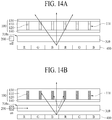
- FIGS. 14a and 14b are brief views illustrating a display device comprising a viewing angle controlling device according to further still another embodiment of the present disclosure, which are a self-light emission display device like an organic light emitting display device, wherein FIG. 14a corresponds to a wide viewing angle mode, and FIG. 14b corresponds to a narrow viewing angle mode.
- the display device comprises viewing angle controlling devices 100 and 200, a light guide plate 310, and a display panel 400.
- the viewing angle controlling devices 100 and 200 include the viewing angle controlling film 100 and the viewing angle controlling light source 200.
- FIGS. 2a and 2b Various modifications may be made to the viewing angle controlling film 100 in the same manner as FIGS. 2a and 2b , FIGS. 3a and 3b , FIGS. 4a to 4c or FIGS. 5a and 5b , and their repeated description will be omitted.
- the viewing angle controlling light source 200 may be arranged to face one side 310a of the light guide plate 310, and the light guide plate 310 may be arranged between the viewing angle controlling film 100 and the display panel 400. Therefore, since the light guide plate 310 may be formed to adjoin the viewing angle controlling film 100, light emitted from the viewing angle controlling light source 200 may be supplied to the viewing angle controlling film 100 through the light guide plate 310, whereby light efficiency may be improved.
- the viewing angle controlling light source 200 and the light guide plate 310 like the structure of the viewing angle controlling light source 200 and the light guide plate 310 except the backlight light source 300 in the aforementioned structure of FIGS. 7a , 8 and 9 . That is, as described with reference to FIG. 6 , the viewing angle controlling light source 200 may be arranged to face the other side 310c of the light guide plate 310. Also, as described with reference to FIG. 8 , the viewing angle controlling light source 200 may be arranged to face the corner surface 310d of the light guide plate 310.
- a photo-reflective pattern 315 for transmitting light emitted from the display panel 400 and reflecting light emitted from the viewing angle controlling light source 200 may additionally be formed on the lower surface 310e of the light guide plate 310.
- the viewing angle controlling light source 200 may be arranged at the end of the other side 310c of the light guide plate 310, and an auxiliary light guide plate 250 may additionally be formed at the other side 310c of the light guide plate 310.
- a convex type condensing pattern 280 may additionally be formed on the upper surface of the light guide plate 310.
- the display panel 400 may be arranged between the light guide plate 310.
- the display panel 400 is made of, but not limited to, an organic light emitting display panel that includes pixels of red (R), green (G) and blue (B).
- the light-transmittance conversion portion 120 provided in the viewing angle controlling film 100 is not reacted with light emitted from the display panel 400, and is reacted with light emitted from the viewing angle controlling light source 200, whereby light transmittance is reversibly changed.
- a viewing angle controlling method of the display device according to further still another embodiment of the present disclosure is as follows.
- the viewing angle controlling light source 200 is maintained at an off-state, the light-transmittance conversion portion 120 becomes a transparent state, whereby the viewing angle controlling film 100 fully becomes transparent. Therefore, the light emitted from the display panel 400 moves toward various directions by transmitting the base 110 and the light-transmittance conversion portion 120, whereby a wide viewing angle mode is realized.
- the viewing angle controlling light source 200 if the viewing angle controlling light source 200 is maintained at an on-state, light emitted from the viewing angle controlling light source 200 is supplied to the viewing angle controlling film 100 through the light guide plate 310 and thus the light-transmittance conversion portion 120 becomes an opaque state, whereby the viewing angle controlling film 100 includes a transparent area (an area of the base 110) and an opaque area (an area of the light-transmittance conversion portion 120). Therefore, the light emitted from the display panel 400 moves to the transparent area only, whereby a narrow viewing angle mode is realized.
- the viewing angle controlling film includes the light-transmittance conversion portion of which light transmittance is reversibly changed by being reacted with light of a predetermined wavelength range
- a viewing angle of the display device may be controlled easily while the viewing angle controlling film is not detachable to a display panel.
Landscapes
- Physics & Mathematics (AREA)
- Nonlinear Science (AREA)
- General Physics & Mathematics (AREA)
- Optics & Photonics (AREA)
- Chemical & Material Sciences (AREA)
- Crystallography & Structural Chemistry (AREA)
- Mathematical Physics (AREA)
- Electroluminescent Light Sources (AREA)
- Liquid Crystal (AREA)
- Planar Illumination Modules (AREA)
Abstract

Description
- This application claims the benefit of the Korean Patent Application No.
10-2017-0065226 filed on May 26, 2017 - The present disclosure relates to a display device, and more particularly, to a display device comprising a viewing angle controlling film.
- A display device comprising a viewing angle controlling device to protect privacy of a user has been devised. That is, a display device which allows only a user to view an image without allowing people near the user to view the image by reducing a viewing angle using the viewing angle controlling device has been devised.
- Hereinafter, a display device comprising a viewing angle controlling device according to the related art will be described with reference to the accompanying drawing.
-
FIG. 1 is a brief view illustrating a display device comprising a viewing angle controlling device according to the related art. - As shown in
FIG. 1 , the display device of the related art comprises adisplay panel 10 and a viewing angle controlling film 20. - The viewing angle controlling film 20 is arranged above the
display panel 10 and controls a viewing angle of an image emitted from thedisplay panel 10. In more detail, since the viewing angle controlling film 20 is provided with a plurality ofbarriers 25 made of a light-shielding material therein, the viewing angle for the image emitted from thedisplay panel 10 is reduced. Therefore, the user can view the image only at a front side of thedisplay panel 10, and has a difficulty in viewing the image at a peripheral side of thedisplay panel 10. - However, if the viewing angle controlling film 20 of the related art is used, the viewing angle of the display device is fixed without being changed, whereby a problem occurs in that the user should always view an image at a narrow viewing angle. To solve this problem, the viewing angle controlling film 20 may detachably be fixed to the
display panel 10. In this case, there is inconvenience that the user should arrange the viewing angle controlling film 20 in person. - Accordingly, the present disclosure is directed to a viewing angle controlling film and a backlight unit using the same and a display device using the same that substantially obviates one or more problems due to limitations and disadvantages of the related art.
- An advantage of the present disclosure is to provide a viewing angle controlling film and a backlight unit using the same and a display device using the same, in which a viewing angle may easily be changed while the viewing angle controlling film is not detachable to a display panel.
- Additional advantages and features of the disclosure will be set forth in part in the description which follows and in part will become apparent to those having ordinary skill in the art upon examination of the following or may be learned from practice of the disclosure. The objectives and other advantages of the disclosure may be realized and attained by the structure particularly pointed out in the written description and claims hereof as well as the appended drawings.
- To achieve the above object, a viewing angle controlling film according to the present disclosure comprises a first area where light transmittance is not converted (with a first light transmissivity, optionally a fixed light transmissivity); and a second area where light transmittance is converted (with a fixed light transmissivity), wherein the second area includes a light-transmittance conversion portion configured to react with light of a predetermined wavelength range to convert the light transmittance and not to react with light of a wavelength range other than the predetermined wavelength range. That is to say, the second area includes a light-transmittance conversion portion configured to decrease its transmissivity when exposed to light of the predetermined wavelength range, while the first area may not be configured to decrease its transmissivity when exposed to light of the predetermined wavelength range.
- In another aspect of the present disclosure, a backlight unit comprises a first light source for emitting first light of a first wavelength range; a second light source for emitting second light of a second wavelength range different from the first wavelength range; and a viewing angle controlling film, wherein the viewing angle controlling film comprises; a first area where light transmittance is not converted; and a second area where light transmittance is converted, wherein the second area includes a light-transmittance conversion portion configured to react with the second light to convert the light transmittance and not to react with the first light.
- In still another aspect of the present disclosure, a display device comprises a first light source for emitting first light of a first wavelength range; a second light source for emitting second light of a second wavelength range different from the first wavelength range; a viewing angle controlling film; and a display panel for displaying an image by being supplied with the first light, wherein the viewing angle controlling film comprises; a first area where light transmittance is not converted; and a second area where light transmittance is converted, wherein the second area includes a light-transmittance conversion portion configured to react with the second light to convert the light transmittance and not to react with the first light.
- In further still another aspect of the present disclosure, a display device comprises a display panel for displaying an image; a light source for emitting light of a predetermined wavelength range; and a viewing angle controlling film, wherein the viewing angle controlling film comprises; a first area where light transmittance is not converted; and a second area where light transmittance is converted, wherein the second area includes a light-transmittance conversion portion configured to react with light of the predetermined wavelength range to convert the light transmittance and not to react with light emitted from the display panel.
- The first area may adjoin the second area laterally.
- A third area with another light transmissivity may be further provided. The third area may include an opaque area having a light-shielding portion, adjoins the second area, optionally while overlapping the second area vertically, and adjoins the first area laterally.
- It is to be understood that both the foregoing general description and the following detailed description of the present disclosure are exemplary and explanatory and are intended to provide further explanation of the disclosure as claimed.
- The accompanying drawings, which are included to provide a further understanding of the disclosure and are incorporated in and constitute a part of this application, illustrate embodiment(s) of the disclosure and together with the description serve to explain the principle of the disclosure. In the drawings:
-
FIG. 1 is a brief view illustrating a display device comprising a viewing angle controlling device according to the related art; -
FIGS. 2a and2b are brief views illustrating a display device comprising a viewing angle controlling device according to one embodiment of the present disclosure, whereinFIG. 2a corresponds to a wide viewing angle mode, andFIG. 2b corresponds to a narrow viewing angle mode; -
FIGS. 3a and 3b are brief views illustrating a display device comprising a viewing angle controlling device according to another embodiment of the present disclosure, whereinFIG. 3a corresponds to a wide viewing angle mode, andFIG. 3b corresponds to a narrow viewing angle mode; -
FIGS. 4a to 4c are brief views illustrating a display device comprising a viewing angle controlling device according to still another embodiment of the present disclosure, whereinFIG. 4a corresponds to a wide viewing angle mode,FIG. 4b corresponds to a middle viewing angle mode, andFIG. 4c corresponds to a narrow viewing angle mode; -
FIGS. 5a and 5b are brief views illustrating a display device comprising a viewing angle controlling device according to another embodiment of the present disclosure; -
FIG. 6 is a brief view illustrating a display device comprising a viewing angle controlling device according to still another embodiment of the present disclosure; -
FIGS. 7a, 7b ,8 and 9 are views illustrating arrangement of a viewing angle controlling light source and a backlight light source according to various embodiments of the present disclosure; -
FIG. 10 is a brief view illustrating a display device comprising a viewing angle controlling device according to further still another embodiment of the present disclosure; -
FIG. 11 is a brief view illustrating a display device comprising a viewing angle controlling device according to further still another embodiment of the present disclosure; -
FIGS. 12a to 12c are brief process views illustrating a method for manufacturing a viewing angle controlling film according to one embodiment of the present disclosure; -
FIGS. 13a to 13c are brief process views illustrating a method for manufacturing a viewing angle controlling film according to another embodiment of the present disclosure; and -
FIGS. 14a and 14b are brief views illustrating a display device comprising a viewing angle controlling device according to further still another embodiment of the present disclosure, whereinFIG. 14a corresponds to a wide viewing angle mode, andFIG. 14b corresponds to a narrow viewing angle mode. - Advantages and features of the present disclosure, and implementation methods thereof will be clarified through following embodiments described with reference to the accompanying drawings. The present disclosure may, however, be embodied in different forms and should not be construed as limited to the embodiments set forth herein. Rather, these embodiments are provided so that this disclosure will be thorough and complete, and will fully convey the scope of the present disclosure to those skilled in the art. Further, the present disclosure is only defined by scopes of claims.
- A shape, a size, a ratio, an angle, and a number disclosed in the drawings for describing embodiments of the present disclosure are merely an example, and thus, the present disclosure is not limited to the illustrated details. Like reference numerals refer to like elements throughout. In the following description, when the detailed description of the relevant known function or configuration is determined to unnecessarily obscure the important point of the present disclosure, the detailed description will be omitted. In a case where 'comprise', 'have', and 'include' described in the present specification are used, another part may be added unless 'only∼' is used. The terms of a singular form may include plural forms unless referred to the contrary.
- In construing an element, the element is construed as including an error range although there is no explicit description.
- In describing a position relationship, for example, when the position relationship is described as 'upon∼', 'above∼', 'below∼', and 'next to∼', one or more portions may be arranged between two other portions unless 'just' or 'direct' is used.
- In describing a time relationship, for example, when the temporal order is described as 'after∼', 'subsequent∼', 'next∼', and 'before∼', a case which is not continuous may be included unless 'just' or 'direct' is used.
- It will be understood that, although the terms "first", "second", etc. may be used herein to describe various elements, these elements should not be limited by these terms. These terms are only used to distinguish one element from another element. For example, a first element could be termed a second element, and, similarly, a second element could be termed a first element, without departing from the scope of the present disclosure.
- Features of various embodiments of the present disclosure may be partially or overall coupled to or combined with each other, and may be variously inter-operated with each other and driven technically as those skilled in the art can sufficiently understand. The embodiments of the present disclosure may be carried out independently from each other, or may be carried out together in co-dependent relationship.
- Hereinafter, various embodiments of the present disclosure will be described in detail with reference to the accompanying drawings.
-
FIGS. 2a and2b are brief views illustrating a display device comprising a viewing angle controlling device according to one embodiment of the present disclosure, whereinFIG. 2a corresponds to a wide viewing angle mode, andFIG. 2b corresponds to a narrow viewing angle mode. - As shown in
FIGS. 2a and2b , the display device according to one embodiment of the present disclosure comprises viewingangle controlling devices light source 300, and adisplay panel 400. - The viewing
angle controlling devices angle controlling film 100 and a viewing angle controllinglight source 200. The viewingangle controlling film 100 may include an area where light transmittance is changed by being reversibly reacted with light emitted from the viewing angle controllinglight source 200 and an area that is always transparent regardless of light emitted from the viewing angle controllinglight source 200, thereby controlling a viewing angle of the display device. - The viewing
angle controlling film 100 includes abase 110, a light-transmittance conversion portion 120, andprotective portions - The
base 110 is made of a transparent material. A plurality ofgrooves 111 are provided in thebase 110. The plurality ofgrooves 111 may be formed to pass through an upper surface to a lower surface of the base 110 as shown. However, the plurality ofgrooves 111 are not limited to the shown example. - The light-
transmittance conversion portion 120 is formed in the plurality ofgrooves 111 of thebase 110. The light-transmittance conversion portion 120 is provided with a plurality of partition walls spaced apart from one another at a predetermined interval. The viewing angle of the display device can be controlled by light-transmittance change of the light-transmittance conversion portion 120. The light-transmittance conversion portion 120 may be filled in, but not limited to, entirety of the plurality ofgrooves 111. - The light-
transmittance conversion portion 120 includes a material of which light transmittance is reversibly changed due to reaction with light emitted from the viewing angle controllinglight source 200. That is, light transmittance of the light-transmittance conversion portion 120 in the case that light is not emitted from the viewing angle controllinglight source 200 is different from light transmittance of the light-transmittance conversion portion 120 in the case that light is emitted from the viewing angle controllinglight source 200. For example, the light-transmittance conversion portion 120 is a transparent state in the case that light is not emitted from the viewing angle controllinglight source 200, and if light is emitted from the viewing angle controllinglight source 200, the light-transmittance conversion portion 120 may be switched to an opaque state by being reacted with the emitted light. This light-transmittance conversion portion 120 may include a material, such as a photochromic material, of which light transmittance is changed due to reversible reaction with light of a specific wavelength. Hereinafter, in this specification, the material of which light transmittance is changed by reversible reaction with light of the specific wavelength will be referred to as a photo-reactive transmittance conversion material. - The photo-reactive transmittance conversion material may be included in the light-
transmittance conversion portion 120 in the range of 1 weight % to 20 weight %. If the photo-reactive transmittance conversion material is included in the light-transmittance conversion portion 120 in the range less than 1 weight %, a light-transmittance variation of the light-transmittance conversion portion 120 is not great even though light is emitted from the viewing angle controllinglight source 200, whereby a viewing angle controlling function may be deteriorated. According to an experiment, if a photochromic material is included in the light-transmittance conversion portion 120 in the range less than 1 weight %, a light-shielding ratio of the light-transmittance conversion portion 120 is reduced to a value less than 70%, whereby it is noted that the viewing angle controlling function is deteriorated. Also, if the photo-reactive transmittance conversion material exceeds 20 weight % of the light-transmittance conversion portion 120, a light-shielding ratio of the light-transmittance conversion portion 120 is not increased greatly and only a process of forming the light-transmittance conversion portion 120 may be difficult. According to the experiment, if the photochromic material is included in the light-transmittance conversion portion 120 in the range of 20 weight %, the light-shielding ratio of the light-transmittance conversion portion 120 is 90% or more, whereby it is noted that the viewing angle controlling function is sufficient. Meanwhile, the light-transmittance conversion portion 120 is formed by including a process of dissolving the photo-reactive transmittance conversion material in a polymer resin. At this time, if the photo-reactive transmittance conversion material exceeds 20 weight % of the light-transmittance conversion portion 120, the process of dissolving the photo-reactive transmittance conversion material in the polymer resin may be difficult. - The
protective portions protective portion 130 and a lowerprotective portion 140. The upperprotective portion 130 is formed on upper surfaces of thebase 110 and the light-transmittance conversion portion 120 to protect the upper surfaces of thebase 110 and the light-transmittance conversion portion 120. The lowerprotective portion 140 is formed on lower surfaces of thebase 110 and the light-transmittance conversion portion 120 to protect the lower surfaces of thebase 110 and the light-transmittance conversion portion 120. The light-transmittance conversion portion 120 is sealed by theprotective portions protective portions - The viewing angle controlling
light source 200 supplies light to the viewingangle controlling film 100 and changes light transmittance of the light-transmittance conversion portion 120. The viewing angle controllinglight source 200 may be made of, but not limited to, a point light source such as LED. The viewing angle controllinglight source 200 emits light of a wavelength different from that of thebacklight light source 300. As an example, thebacklight light source 300 may emit light of a visible ray wavelength while the viewing angle controllinglight source 200 may emit light of a short wavelength of 400nm or less. In this case, the light-transmittance conversion portion 120 may include a photo-reactive transmittance conversion material reversibly reacted with light of a short wavelength of 400nm or less. - The
backlight light source 300 serves to supply light to thedisplay panel 400. Thebacklight light source 300 may be made of, but not limited to, a point light source such as LED. As described above, thebacklight light source 300 emits light of a wavelength different from that of the viewing angle controllinglight source 200. Particularly, the light emitted from thebacklight light source 300 does not change light transmittance of the light-transmittance conversion portion 120. As an example, the light-transmittance conversion portion 120 is reversibly reacted with light of a short wavelength of 400nm or less emitted from the viewing angle controllinglight source 200, whereby its light transmittance is changed. However, the light-transmittance conversion portion 120 is not reacted with light of a visible ray wavelength emitted from thebacklight light source 300, whereby its light transmittance is not changed. - The
backlight light source 300 and the viewing angle controllinglight source 200 may be arranged below the viewingangle controlling film 100. Various modifications may be made to a detailed arrangement of thebacklight light source 300 and the viewing angle controllinglight source 200, and will be described later. - The
display panel 400 may be arranged above the viewingangle controlling film 100. Thedisplay panel 400 may be made of a liquid crystal display panel which is a non-light emission panel, and thus may display an image through light emitted from thebacklight light source 300. However, thedisplay panel 400 according to the present disclosure is not limited to the liquid crystal panel. For example, thedisplay panel 400 may be made of a self-light emission panel like an organic light emitting panel. In this case, thebacklight light source 300 is not required. Thedisplay panel 400 includes pixels of red (R), green (G) and blue (B). - A viewing angle controlling method of the display device according to one embodiment of the present disclosure is as follows.
- As shown in
FIG. 2a , if the viewing angle controllinglight source 200 is maintained at an off-state, the light-transmittance conversion portion 120 becomes a transparent state, whereby the viewingangle controlling film 100 becomes transparent. Therefore, the light emitted from thebacklight light source 300 moves toward various directions by transmitting thebase 110 and the light-transmittance conversion portion 120, whereby a wide viewing angle mode is realized. - As shown in
FIG. 2b , if the viewing angle controllinglight source 200 is maintained at an on-state, the light-transmittance conversion portion 120 becomes an opaque state, whereby the viewingangle controlling film 100 includes a transparent area (an area of the base 110) and an opaque area (an area of the light-transmittance conversion portion 120). Therefore, the light emitted from thebacklight light source 300 moves to the transparent area only, whereby a narrow viewing angle mode is realized. - Although not shown, the light-
transmittance conversion portion 120 may be provided in such a manner that the light-transmittance conversion portion 120 becomes an opaque state to realize the narrow viewing angle mode when the viewing angle controllinglight source 200 is maintained at an off-state, and the light-transmittance conversion portion 120 becomes a transparent state to realize the wide viewing angle mode when the viewing angle controllinglight source 200 is maintained at an on-state. - Meanwhile, in the narrow viewing angle mode, when the light emitted from the
backlight light source 300, moving toward the transparent area passes through thedisplay panel 400 where the pixels of red (R), green (G) and blue (B) are arranged regularly, a moire phenomenon occurs due to a relation between movement of the light and arrangement of the pixels, whereby image quality may be deteriorated. Therefore, to prevent the moire phenomenon from occurring, as shown in portions drawn out of arrows ofFIG. 2a , a plurality ofbeads 150 may be included in theprotective portions beads 150 are provided in theprotective portions backlight light source 300, moving toward the transparent area only is diffracted or diffused while colliding with thebeads 150, whereby the moire phenomenon may be reduced. Thebeads 150 may be included in both the upperprotective portion 130 and the lowerprotective portion 140 but may be included in any one of the upperprotective portion 130 and the lowerprotective portion 140. -
FIGS. 3a and 3b are brief views illustrating a display device comprising a viewing angle controlling device according to another embodiment of the present disclosure, whereinFIG. 3a corresponds to a wide viewing angle mode, andFIG. 3b corresponds to a narrow viewing angle mode. - The display device of
FIGS. 3a and 3b are the same as that ofFIGS. 2a and2b except that the viewingangle controlling film 100 is changed. Therefore, the same reference numerals are given to the same elements, and only elements different from those ofFIGS. 2a and2b will be described hereinafter. - According to another embodiment of the present disclosure, the viewing
angle controlling film 100 may include an area of which light transmittance is changed by reversible reaction with light emitted from the viewing angle controllinglight source 200, an area always transparent regardless of the light emitted from the viewing angle controllinglight source 200, and an area always opaque regardless of the light emitted from the viewing angle controllinglight source 200, whereby the viewing angle of the display device may be controlled. - The viewing
angle controlling film 100 according to another embodiment of the present disclosure includes abase 110, a light-transmittance conversion portion 120, a light-shieldingportion 160, andprotective portions - The
base 110 is made of a transparent material in the same manner as the aforementioned embodiment, and includes a plurality ofgrooves 111. - The light-
transmittance conversion portion 120 is formed in the plurality ofgrooves 111 of thebase 110. Particularly, the light-transmittance conversion portion 120 is formed in a part of each of the plurality ofgrooves 111, and the light-shieldingportion 160 is formed in the other part of each of the plurality ofgrooves 111. That is, the light-transmittance conversion portion 120 and the light-shieldingportion 160 are formed in the plurality ofgrooves 111 while overlapping and adjoining each other. Since detailed elements of the light-transmittance conversion portion 120 are the same as the aforementioned elements, their repeated description will be omitted. - The light-shielding
portion 160 is formed in the plurality ofgrooves 111 of the base 110 while overlapping the light-transmittance conversion portion 120 as described above. The light-shieldingportion 160 includes a light-shielding material, such as carbon black, known in the art. As shown, the light-shieldingportion 160 may be arranged below, but not limited to, the light-transmittance conversion portion 120. The light-shieldingportion 160 may be arranged above the light-transmittance conversion portion 120. - As described above, according to another embodiment of the present disclosure, the viewing
angle controlling film 100 includes the light-shieldingportion 160, whereby the narrow viewing angle mode may be more smoothly realized. This will be described in more detail. The light-transmittance conversion portion 120 may be converted to an opaque state by the light emitted from the viewing angle controllinglight source 200. At this time, a light-shielding ratio of the light-transmittance conversion portion 120 may be changed depending on a content of the photo-reactive transmittance conversion material, whereby it might be possible that light may pass through the light-transmittance conversion portion 120 to some extent. Therefore, if the narrow viewing angle mode is realized through the light-transmittance conversion portion 120 only, the light may partially be transmitted, whereby it may be difficult to fully realize the narrow viewing angle mode In another embodiment of the present disclosure, since the light-shieldingportion 160 is additionally included, the light-shielding ratio of the light-shieldingportion 160 may be increased, whereby the narrow viewing angle mode may be realized more smoothly. - A ratio (h1:h2) of a height h1 of the light-shielding
portion 160 to a height h2 of the light-transmittance conversion portion 120 may be in the range of 5:95 to 50:50. If the height h1 of the light-shieldingportion 160 is lower than the above range, it is not likely to obtain a smooth realization effect of the narrow viewing angle mode, and if the height h1 of the light-shieldingportion 160 is higher than the above range, it may be difficult to realize the wide viewing angle mode. - The
protective portions protective portion 130 and the lowerprotective portion 140. The light-transmittance conversion portion 120 and the light-shieldingportion 160 are sealed by theprotective portions protective portions - A viewing angle controlling method of the display device according to another embodiment of the present disclosure is as follows.
- As shown in
FIG. 3a , if the viewing angle controllinglight source 200 is maintained at an off-state, the light-transmittance conversion portion 120 becomes a transparent state. Therefore, the viewingangle controlling film 100 except the light-shieldingportion 160 becomes transparent, whereby the light emitted from thebacklight light source 300 moves toward various directions by transmitting thebase 110 and the light-transmittance conversion portion 120, whereby a wide viewing angle mode is realized. - As shown in
FIG. 3b , if the viewing angle controllinglight source 200 is maintained at an on-state, the light-transmittance conversion portion 120 becomes an opaque state, whereby the viewingangle controlling film 100 includes a transparent area (an area of the base 110) and an opaque area (an area of the light-transmittance conversion portion 120 and the light-shielding portion 160). Therefore, the light emitted from thebacklight light source 300 moves to the transparent area only, whereby a narrow viewing angle mode is realized. -
FIGS. 4a to 4c are brief views illustrating a display device comprising a viewing angle controlling device according to still another embodiment of the present disclosure, whereinFIG. 4a corresponds to a wide viewing angle mode,FIG. 4b corresponds to a middle viewing angle mode, andFIG. 4c corresponds to a narrow viewing angle mode. - The display device of
FIGS. 4a to 4c are the same as that ofFIGS. 2a and2b except that the light-transmittance conversion portion 120 and the viewing angle controllinglight source 200 are changed. Therefore, the same reference numerals are given to the same elements, and only elements different from those ofFIGS. 2a and2b will be described hereinafter. - According to still another embodiment of the present disclosure, the light-
transmittance conversion portion 120 in the viewingangle controlling film 100 includes a first light-transmittance conversion portion 121 and a second light-transmittance conversion portion 122. The first light-transmittance conversion portion 121 and the second light-transmittance conversion portion 122 are formed in the plurality ofgrooves 111 of the base 110 while overlapping and adjoining each other. That is, the first light-transmittance conversion portion 121 is formed in a part of each of the plurality ofgrooves 111, and the second light-transmittance conversion portion 122 is formed in the other part of each of the plurality ofgrooves 111. The first light-transmittance conversion portion 121 may be arranged below or above the second light-transmittance conversion portion 122. - The viewing angle controlling
light source 200 includes a first viewing angle controllinglight source 210 and a second viewing angle controllinglight source 220. The first viewing angle controllinglight source 210 emits light of a wavelength different from that of each of the second viewing angle controllinglight source 220 and thebacklight light source 300. Also, the second viewing angle controllinglight source 220 emits light of a wavelength different from that of each of the first viewing angle controllinglight source 210 and thebacklight light source 300. As an example, thebacklight light source 300 may emit light of a visible ray wavelength while the first viewing angle controllinglight source 210 and the second viewing angle controllinglight source 220 may emit their respective light of a short wavelength of 400nm or less. - The first light-
transmittance conversion portion 121 includes a material of which light transmittance is reversibly changed by being reacted with light emitted from the first viewing angle controllinglight source 210. Also, the first light-transmittance conversion portion 121 is made of a material of which light transmittance is maintained without being reacted with the light emitted from the second viewing angle controllinglight source 220 and thebacklight light source 300. Therefore, light transmittance of the first light-transmittance conversion portion 121 in the case that the light is not emitted from the first viewing angle controllinglight source 210 is different from light transmittance of the first light-transmittance conversion portion 121 in the case that the light is emitted from the first viewing angle controllinglight source 210. For example, the first light-transmittance conversion portion 121 is a transparent state in the case that light is not emitted from the first viewing angle controllinglight source 210, and if the light is emitted from the first viewing angle controllinglight source 210, the first light-transmittance conversion portion 121 may be switched to an opaque state by being reacted with the emitted light. - The second light-
transmittance conversion portion 122 includes a material of which light transmittance is reversibly changed by being reacted with the light emitted from the second viewing angle controllinglight source 220. Also, the second light-transmittance conversion portion 122 is made of a material of which light transmittance is maintained without being reacted with the light emitted from the first viewing angle controllinglight source 210 and thebacklight light source 300. Therefore, light transmittance of the second light-transmittance conversion portion 122 in the case that the light is not emitted from the second viewing angle controlling light source 212 is different from light transmittance of the second light-transmittance conversion portion 122 in the case that the light is emitted from the second viewing angle controllinglight source 220. For example, the second light-transmittance conversion portion 122 is a transparent state in the case that light is not emitted from the second viewing angle controllinglight source 220, and if the light is emitted from the second viewing angle controllinglight source 220, the second light-transmittance conversion portion 122 may be switched to an opaque state by being reacted with the emitted light. - According to still another embodiment of the present disclosure, as described above, the viewing angle may be modified to more various angles. A viewing angle controlling method of the display device according to still another embodiment of the present disclosure is as follows.
- As shown in
FIG. 4a , if the first viewing angle controllinglight source 210 and the second viewing angle controllinglight source 220 are maintained at off-states, the first light-transmittance conversion portion 121 and the second light-transmittance conversion portion 122 become transparent states. Therefore, the viewingangle controlling film 100 fully becomes transparent, whereby the light emitted from thebacklight light source 300 moves toward various directions by transmitting thebase 110, the first light-transmittance conversion portion 121 and the second light-transmittance conversion portion 122, whereby a wide viewing angle mode is realized. - As shown in
FIG. 4b , if the first viewing angle controllinglight source 210 is maintained at an on-state and the second viewing angle controllinglight source 220 is maintained at an off-state, the first light-transmittance conversion portion 121 becomes an opaque state and the second light-transmittance conversion portion 122 becomes a transparent state. Therefore, the viewingangle controlling film 100 includes a transparent area (areas of thebase 110 and the second light-transmittance conversion portion 122) and an opaque area (an area of the first light-transmittance conversion portion 121). Therefore, the light emitted from thebacklight light source 300 moves to the transparent area, whereby a middle viewing angle mode is realized. At this time, if a height of the first light-transmittance conversion portion 121 is controlled properly, an angle of the middle viewing angle may be controlled properly. - As shown in
FIG. 4c , if the first viewing angle controllinglight source 210 is maintained at an on-state and the second viewing angle controllinglight source 220 is maintained at an on-state, the first light-transmittance conversion portion 121 and the second light-transmittance conversion portion 122 become opaque states. Therefore, the viewingangle controlling film 100 includes a transparent area (an area of the base 110) and an opaque area (areas of the first light-transmittance conversion portion 121 and the second light-transmittance conversion portion 122). Therefore, the light emitted from thebacklight light source 300 moves to the transparent area, whereby a narrow viewing angle mode is realized. -
FIGS. 5a and 5b are brief views illustrating a display device comprising a viewing angle controlling device according to further still another embodiment of the present disclosure, whereinFIG. 5a corresponds to a wide viewing angle mode, andFIG. 5b corresponds to a narrow viewing angle mode. - The display device of
FIGS. 5a and 5b are the same as that ofFIGS. 2a and2b except that the light-transmittance conversion portion 120 is changed. Therefore, the same reference numerals are given to the same elements, and only elements different from those ofFIGS. 2a and2b will be described hereinafter. - According to further still another embodiment of the present disclosure, the light-
transmittance conversion portion 120 in the viewingangle controlling film 100 includes a first light-transmittance conversion portion 121 and a second light-transmittance conversion portion 122. The first light-transmittance conversion portion 121 and the second light-transmittance conversion portion 122 are formed in the plurality ofgrooves 111 of the base 110 while overlapping and adjoining each other. That is, the first light-transmittance conversion portion 121 is formed in a part of each of the plurality ofgrooves 111, and the second light-transmittance conversion portion 122 is formed in the other part of each of the plurality ofgrooves 111. The first light-transmittance conversion portion 121 may be arranged below or above the second light-transmittance conversion portion 122. - The first light-
transmittance conversion portion 121 and the second light-transmittance conversion portion 122 include a material of which light transmittance is reversibly changed by being reacted with light emitted from the viewing angle controllinglight source 200. At this time, a content of a photo-reactive transmittance conversion material contained in the first light-transmittance conversion portion 121 is different from that of a photo-reactive transmittance conversion material contained in the second light-transmittance conversion portion 122. As an example, the content of the photo-reactive transmittance conversion material contained in the first light-transmittance conversion portion 121 is more than that of the photo-reactive transmittance conversion material contained in the second light-transmittance conversion portion 122. In this case, the first light-transmittance conversion portion 121 is reacted with the light emitted from the viewing angle controllinglight source 200 to have a relatively high light-shielding ratio, and the second light-transmittance conversion portion 122 is reacted with the light emitted from the viewing angle controllinglight source 200 to have a relatively low light-shielding ratio. - A viewing angle controlling method of the display device according to further still another embodiment of the present disclosure is as follows.
- As shown in
FIG. 5a , if the viewing angle controllinglight source 200 is maintained at an off-state, the first light-transmittance conversion portion 121 and the second light-transmittance conversion portion 122 become transparent states. Therefore, the viewingangle controlling film 100 fully becomes transparent, whereby the light emitted from thebacklight light source 300 moves toward various directions by transmitting thebase 110, the first light-transmittance conversion portion 121 and the second light-transmittance conversion portion 122, whereby a wide viewing angle mode is realized. - As shown in
FIG. 5b , if the viewing angle controllinglight source 210 is maintained at an on-state, the first light-transmittance conversion portion 121 and the second light-transmittance conversion portion 122 become opaque states. Therefore, the viewingangle controlling film 100 includes a transparent area (an area of the base 110) and an opaque area (areas of the first light-transmittance conversion portion 121 and the second light-transmittance conversion portion 122). Therefore, the light emitted from thebacklight light source 300 moves to the transparent area, whereby a narrow viewing angle mode is realized. - Meanwhile, if the viewing angle controlling
light source 200 is maintained at an on-state, the first light-transmittance conversion portion 121 may become an opaque state and the second light-transmittance conversion portion 122 may become a semi-transparent state. In this case, the viewingangle controlling film 100 includes a transparent area (an area of the base 110), an opaque area (an area of the first light-transmittance conversion portion 121), and a semi-transparent area (an area of the second light-transmittance conversion portion 122). Therefore, the light emitted from thebacklight light source 300 moves to the transparent area and partially moves to the semi-transparent area, whereby a middle viewing angle mode may be realized. -
FIG. 6 is a brief view illustrating a display device comprising a viewing angle controlling device according to still another embodiment of the present disclosure, wherein the display device relates to a liquid crystal display device. - As shown in
FIG. 6 , the display device according to still another embodiment of the present disclosure comprises viewingangle controlling devices backlight unit 301, and adisplay panel 400. - The viewing
angle controlling devices angle controlling film 100 and a viewing angle controllinglight source 200. Various modifications may be made to the viewingangle controlling film 100 and the viewing angle controllinglight source 200 as shown inFIGS. 2a and2b ,FIGS. 3a and 3b ,FIGS. 4a to 4c orFIGS. 5a and 5b , and their repeated description will be omitted. - The
backlight unit 301 includes abacklight light source 300, alight guide plate 310, anoptical film 320, and areflective plate 330. - The
backlight light source 300 emits light of a wavelength different from that of the viewing angle controllinglight source 200 as described above. Particularly, the light emitted from thebacklight light source 300 does not change light transmittance of the light-transmittance conversion portion 120 in the viewingangle controlling film 100. Thebacklight light source 300 faces thelight guide plate 310, and the light emitted from thebacklight light source 300 enters thelight guide plate 310 and then its moving direction is changed in thelight guide plate 310, whereby the light moves toward theoptical film 320. - The
light guide plate 310 changes the moving direction of the light emitted from thebacklight light source 300 toward theoptical film 320, and various modifications known in the art may be made to thelight guide plate 310. - The
optical film 320 is arranged above thelight guide plate 310 and serves to uniformly emit light incident through thelight guide plate 310. Theoptical film 320 may be made of a combination of a plurality of optical sheets such as diffusion sheet and prism sheet, and various modifications known in the art may be made to theoptical film 320. - The
reflective plate 330 is arranged below thelight guide plate 310 and serves to reflect light, which moves to the lower portion of thelight guide plate 310, toward the upper portion of thelight guide plate 310. Various modifications known in the art may be made to thereflective plate 330. - The
display panel 400 is made of a liquid crystal display panel that includes pixels of red (R), green (G) and blue (B). - In case of the display device according to
FIG. 6 , when the light emitted from thebacklight unit 301 passes though thedisplay panel 400, an image is displayed, and the wide viewing angle mode or the narrow viewing angle mode may be controlled by the viewingangle controlling devices - At this time, the viewing
angle controlling film 100 is arranged between thedisplay panel 400 and the viewing angle controllinglight source 200 and between thedisplay panel 400 and thebacklight light source 300. Therefore, light transmittance of the viewingangle controlling film 100 is converted by the light emitted from the viewing anglelight source 200, and the light emitted from thebacklight light source 300 passes through the viewingangle controlling film 100 of which light transmittance is converted, whereby the narrow viewing angle mode or the wide viewing angle mode may be realized. - Therefore, although the viewing
angle controlling film 100 may be formed between thedisplay panel 400 and theoptical film 320 as shown, the viewingangle controlling film 100 may be formed between theoptical film 320 and thelight guide plate 310. However, since the viewingangle controlling film 100 may be arranged to adjoin thedisplay panel 400 to realize the narrow viewing angle mode more smoothly, it may be preferable that the viewingangle controlling film 100 is formed between thedisplay panel 400 and theoptical film 320. That is, if the viewingangle controlling film 100 is formed between theoptical film 320 and thelight guide plate 310, since the light which has passed through the viewingangle controlling film 100 again passes through theoptical film 320 and then enters thedisplay panel 400, the viewing angle may be changed when the light passes through theoptical film 320. In this specification, when any one element adjoins another element, this means that a third element is not interposed between these elements. - In case of the display device according to
FIG. 6 , the viewing angle controllinglight source 200 is included in thebacklight unit 301. That is, the viewing angle controllinglight source 200 is included in thebacklight unit 301 made of a separate assembly body. In this specification, thebacklight unit 301 means an assembly body that elements such as thelight guide plate 310 and thereflective plate 330 are received and coupled by a guide frame and/or a case. - In detail, the viewing angle controlling
light source 200 faces thelight guide plate 310, and thus the light emitted from the viewing angle controllinglight source 200 enters thelight guide plate 310 and then its moving direction is changed, whereby the light passes through theoptical film 320 and then enters the viewingangle controlling film 100. - As described above, since the viewing angle controlling
light source 200 is included in thebacklight unit 301, the viewing angle controllinglight source 200 may be driven using a driving circuit for driving thebacklight unit 301. Therefore, the viewing angle of the display device may be controlled without a separate driving portion. - Meanwhile, the viewing
angle controlling film 100 may be included in thebacklight unit 301, and this is equally applied to the following various embodiments. -
FIGS. 7a, 7b ,8 and 9 are views illustrating arrangement of the viewing angle controllinglight source 200 and thebacklight light source 300 according to various embodiments of the present disclosure. This arrangement may be applied to the aforementioned display device ofFIG. 6 . - As shown in
FIG. 7a , thebacklight light source 300 may be arranged at oneside 310a of thelight guide plate 310, and the viewing angle controllinglight source 200 may be arranged at theother side 310c of thelight guide plate 310. In this case, the light emitted from thebacklight light source 300 enters oneside 310a of thelight guide plate 310 and then its moving direction is changed, whereby the light is emitted through anupper surface 310b of thelight guide plate 310. The light emitted from the viewing angle controllinglight source 200 enters theother side 310c of thelight guide plate 310 and then its moving direction is changed, whereby the light is emitted through theupper surface 310b of thelight guide plate 310. - As shown in
FIG. 7b , the viewing angle controllinglight source 200 and thebacklight light source 300 may be arranged alternately at oneside 310a of thelight guide plate 310. In this case, the light emitted from the viewing angle controllinglight source 200 and the light emitted from thebacklight light source 300 enter oneside 310a of thelight guide plate 310 and then their moving directions are changed, whereby the light emitted from the viewing angle controllinglight source 200 and the light emitted from thebacklight light source 300 are emitted through theupper surface 310b of thelight guide plate 310. - As shown in
FIG. 8 , thebacklight light source 300 may be arranged at oneside 310a of thelight guide plate 310, and the viewing angle controllinglight source 200 may be arranged at corner surfaces 310d of both ends of theother side 310c of thelight guide plate 310. The viewing angle controllinglight source 200 may be arranged only at thecorner surface 310d of any one end of theother side 310c of thelight guide plate 310. Thecorner surface 310d of theother side 310c of thelight guide plate 310 may be provided in a chamfering type, and the viewing angle controllinglight source 200 is arranged to face the chamferingtype corner surface 310d. In this case, the light emitted from thebacklight light source 300 enters oneside 310a of thelight guide plate 310 and then its moving direction is changed, whereby the light is emitted through theupper surface 310b of thelight guide plate 310. The light emitted from the viewing angle controllinglight source 200 enters thecorner surface 310d of thelight guide plate 310 and then its moving direction is changed, whereby the light is emitted through theupper surface 310b of thelight guide plate 310. - In the embodiment of
FIG. 8 , since the number of the viewing angle controllinglight sources 200 is smaller than that inFIGS. 7a and 7b , it may be preferable to improve efficiency of light emitted through theupper surface 310b of thelight guide plate 310 after being emitted from the viewing angle controllinglight source 200. To this end, as shown from a portion drawn out of an arrow inFIG. 8 , a photo-reflective pattern 315 may additionally be formed on alower surface 310e of thelight guide plate 310. - It is preferable that the photo-
reflective pattern 315 includes a material for transmitting the light emitted from thebacklight light source 300, for example, light of a visible ray wavelength range without reflecting the corresponding light while reflecting the light emitted from the viewing angle controllinglight source 200, for example, light of a short wavelength range of 400nm or less. Therefore, a moving path of the light emitted from thebacklight light source 300 may not be changed by the photo-reflective pattern 315. The photo-reflective pattern 315 may be made of, but not limited to, a dot pattern. Also, the photo-reflective pattern 315 may be protruded on thelower surface 310e of thelight guide plate 310 in a convex structure, but may be inserted into thelower surface 310e of thelight guide plate 310 in a concave structure. - The photo-
reflective pattern 315 may be applied to the aforementioned structure according toFIGS. 7a and 7b and a structure according toFIGS. 10 and 11 , which will be described later, as well as the structure according toFIG. 8 . - As will be aware of it from
FIG. 9 , thebacklight light source 300 may be arranged at oneside 310a of thelight guide plate 310, and the viewing angle controllinglight source 200 may be arranged at both ends of theother side 310c of thelight guide plate 310. The viewing angle controllinglight source 200 may be arranged only at any one end of theother side 310c of thelight guide plate 310. - An auxiliary
light guide plate 250 is additionally formed at theother side 310c of thelight guide plate 310. The auxiliarylight guide plate 250 is extended longitudinally along theother side 310c of thelight guide plate 310. The viewing angle controllinglight source 200 is arranged to face the end of the auxiliarylight guide plate 250. In this case, the light emitted from thebacklight light source 300 enters oneside 310a of thelight guide plate 310 and then its moving direction is changed, whereby the light is emitted through theupper surface 310b of thelight guide plate 310. The light emitted from the viewing angle controllinglight source 200 enters the auxiliarylight guide plate 250 and then its moving direction is changed, whereby the light again enters thelight guide plate 310. Afterwards, the moving direction of the light is changed on thelight guide plate 310, whereby the light is emitted through theupper surface 310b of thelight guide plate 310. - In the embodiment of
FIG. 9 , the light emitted from the viewing angle controlling light source 20 which is a point light source enters the auxiliarylight guide plate 250 and then is emitted toward thelight guide plate 310 in the form of a linear light source, whereby light efficiency may be improved. The auxiliarylight guide plate 250 may include, but not limited to, an optical cable. -
FIG. 10 is a brief view illustrating a display device comprising a viewing angle controlling device according to further still another embodiment of the present disclosure, wherein the display device relates to a liquid crystal display device. - The display device of
FIG. 10 is the same as that ofFIG. 6 except that the light-transmittance conversion portion 120 and thelight guide plate 310 are changed. Therefore, the same reference numerals are given to the same elements, and only elements different from those ofFIG. 6 will be described hereinafter. - As shown in
FIG. 10 , thelight guide plate 310 includes a firstlight guide plate 311 and a secondlight guide plate 312. - The first
light guide plate 311 is arranged between theoptical film 320 and thereflective plate 330, and the secondlight guide plate 312 is arranged between theoptical film 320 and the viewingangle controlling film 100. That is, the secondlight guide plate 312 is arranged above the firstlight guide plate 311 while overlapping the firstlight guide plate 311 by interposing theoptical film 320 therebetween. Particularly, theoptical film 320 is not formed above the secondlight guide plate 312, whereby the secondlight guide plate 312 is arranged to adjoin the viewingangle controlling film 100. - The first
light guide plate 311 serves to change a moving direction of light emitted from thebacklight light source 300 toward theoptical film 320, and the secondlight guide plate 312 serves to change a moving direction of light emitted from the viewing angle controllinglight source 200 toward the viewingangle controlling film 100. Therefore, thebacklight light source 300 is arranged to face oneside 311a of the firstlight guide plate 311, and the viewing angle controllinglight source 200 is arranged to face oneside 312a of the secondlight guide plate 312. As a result, the viewing angle controllinglight source 200 is arranged above thebacklight light source 300. As shown, the viewing angle controllinglight source 200 and thebacklight light source 300 may be arranged to overlap each other. However, without limitation to this case, the viewing angle controllinglight source 200 and thebacklight light source 300 may be arranged not to overlap each other. As an example, the viewing angle controllinglight source 200 may be arranged to face theother side 312b of the secondlight guide plate 312, and thebacklight light source 300 may be arranged to face oneside 311 a of the firstlight guide plate 311. Alternatively, the viewing angle controllinglight source 200 may be arranged to face oneside 312a of the secondlight guide plate 312, and thebacklight light source 300 may be arranged to face theother side 311b of the firstlight guide plate 311. Various modifications may be made to the structure of the viewing angle controllinglight source 200 and the secondlight guide plate 312 like the structure of the viewing angle controllinglight source 200 and thelight guide plate 310 except thebacklight light source 300 in the aforementioned structure ofFIGS. 7a ,8 and 9 . - In case of the aforementioned display device according to
FIG. 6 , the light emitted from the viewing angle controllinglight source 200 enters the viewingangle controlling film 100 by passing through thelight guide plate 310 and theoptical film 320. At this time, if light of a short wavelength range of 400nm or less is emitted from the viewing angle controllinglight source 200, more light of the short wavelength may be absorbed in thelight guide plate 310 and theoptical film 320, whereby light transmittance of the viewingangle controlling film 100 may not be converted easily. - On the contrary, in case of the display device according to
FIG. 10 , the light emitted from the viewing angle controllinglight source 200 enters the viewingangle controlling film 100 by passing through the secondlight guide plate 312 only without passing through theoptical film 320. Therefore, in case of the display device according toFIG. 10 , the amount of light emitted from the viewing angle controllinglight source 200 and then entering the viewingangle controlling film 100 may be more increased than the display device according toFIG. 6 , whereby light transmittance of the viewingangle controlling film 100 may be converted relatively easily. - Meanwhile, as shown in a portion drawn out of an arrow in
FIG. 10 , a convextype condensing pattern 280 may additionally be formed on an upper surface of the secondlight guide plate 312. The condensingpattern 280 may be formed in a semi-spherical structure. That is, the condensingpattern 280 may comprise a purality hemispheres on the surface of the secondlight guide plate 312. If thecondensing pattern 280 is additionally formed, an emission rate of light emitted from the viewing angle controllinglight source 200 and then emitted through the secondlight guide plate 312 may be increased, whereby light transmittance of the viewingangle controlling film 100 may be converted more easily. - According to an experiment, it is noted that the amount of light emitted through the second
light guide plate 312 is increased if a ratio H/L of a height H to a lower width L of thecondensing pattern 280 is increased. Particularly, it is noted that the emission rate of the light emitted through the secondlight guide plate 312 is 50% or more if the ratio H/L is 0.5 or more. It is also noted that the emission rate of the light emitted through the secondlight guide plate 312 is 90% or more if the ratio H/L is 1.0. Therefore, it may be preferable to form thecondensing pattern 280 such that the ratio H/L is in the range of 0.5 to 1.0. If the ratio H/L exceeds 1.0, the emission rate is not increased greatly and the process of forming thecondensing pattern 280 may be difficult. - The condensing
pattern 280 may be applied to the aforementioned structure ofFIGS. 6 to 9 and a structure ofFIG. 11 , which will be described later, as well as the structure ofFIG. 10 . -
FIG. 11 is a brief view illustrating a display device comprising a viewing angle controlling device according to further still another embodiment of the present disclosure, wherein the display device relates to a liquid crystal display device. The display device according toFIGS. 6 to 10 relates to an edge type liquid crystal display device comprising alight guide plate 310 andlight sources light guide plate 310, whereas the display device ofFIG. 11 relates to a direct type liquid crystal display device which does not comprise a light guide plate, and compriseslight sources display panel 400. - As shown in
FIG. 11 , the display device according to further still another embodiment of the present disclosure comprises adisplay panel 400, a viewingangle controlling film 100 arranged below thedisplay panel 400, and abacklight unit 301 arranged below the viewingangle controlling film 100. - The
display panel 400 and the viewingangle controlling film 100 may be modified in the same manner as the aforementioned various embodiments. Therefore, their repeated description will be omitted. - The
backlight unit 301 includes anoptical film 320 arranged below the viewingangle controlling film 100, the viewing angle controllinglight source 200 and thebacklight light source 300 arranged below theoptical film 320, and areflective plate 330 arranged below the viewing angle controllinglight source 200 and thebacklight light source 300. The viewing angle controllinglight source 200 and thebacklight light source 300 may be arranged alternately and repeatedly between theoptical film 320 and thereflective plate 330. Various modifications such as various direct type backlight units known in the art can be made to the detailed configuration of thebacklight unit 301. -
FIGS. 12a to 12c are brief process views illustrating a method for manufacturing a viewingangle controlling film 100 according to one embodiment of the present disclosure. - First, as shown in
FIG. 12a , abase 110 and a light-transmittance conversion portion 120 are deposited alternately in a vertical direction. Afterwards, thebase 110 and the light-transmittance conversion portion 120 are subjected to thermal compression to obtain a predetermined deposition structure. - Next, as shown in
FIG. 12b , the deposition structure is cut in a vertical direction to obtain a structure that thebase 110 and the light-transmittance conversion portion 120 are arranged alternately. - Next, as shown in
FIG. 12c , thebase 110 and the light-transmittance conversion portion 120 are positioned to be arranged alternately in a horizontal direction, and then an upperprotective portion 130 is formed on thebase 110 and the light-transmittance conversion portion 120 and a lowerprotective portion 140 is formed below thebase 110 and the light-transmittance conversion portion 120. Although not shown in detail, the upperprotective portion 130 and the lowerprotective portion 140 may be attached to thebase 110 and the light-transmittance conversion portion 120 by a transparent adhesive. - In case of the viewing
angle controlling film 100 according to one embodiment of the present disclosure, which is manufactured by the process according toFIGS. 12a to 12c , a width W of the light-transmittance conversion portion 120 may be formed uniformly. -
FIGS. 13a to 13c are brief process views illustrating a method for manufacturing a viewing angle controlling film according to another embodiment of the present disclosure. - First, as shown in
FIG. 13a , thebase 110 is formed on the lowerprotective portion 140. In detail, a material layer for thebase 110 is deposited on the lowerprotective portion 140 and then a predetermined mold is inserted into the material layer for thebase 110, whereby the base 110 having a plurality ofgrooves 111 is formed. At this time, it is preferable that an end width of the mold gradually becomes smaller to allow the inserted mold to be easily taken out of the material layer for thebase 110. Therefore, a width D of thegroove 111 may be provided to become smaller from top to bottom. Also, it is preferable that the mold is not in contact with the lowerprotective portion 140 to allow the upper surface of the lowerprotective portion 140 not to be damaged by the inserted mold. Therefore, thegrooves 111 are formed so as not to pass through the lower surface of thebase 110. - Next, as shown in
FIG. 13b , the light-transmittance conversion portion 120 is formed in thegrooves 111 of thebase 110. The light-transmittance conversion portion 120 may be formed by the process of depositing the light-transmittance conversion portion 120 inside and outside thegrooves 111 of thebase 110 and then removing the portion where the light-transmittance conversion portion 120 is deposited outside the grooves of the base 110 by using a stripper. - Next, as shown in
FIG. 13c , the upperprotective portion 130 is formed on thebase 110 and the light-transmittance conversion portion 120. Although not shown in detail, the upperprotective portion 130 may be attached to thebase 110 and the light-transmittance conversion portion 120 by a transparent adhesive. - In case of the viewing
angle controlling film 100 according to another embodiment of the present disclosure, which is manufactured by the process according toFIGS. 13a to 13c , the width W of the light-transmittance conversion portion 120 is not uniform and may be provided to become smaller from top to bottom. -
FIGS. 14a and 14b are brief views illustrating a display device comprising a viewing angle controlling device according to further still another embodiment of the present disclosure, which are a self-light emission display device like an organic light emitting display device, whereinFIG. 14a corresponds to a wide viewing angle mode, andFIG. 14b corresponds to a narrow viewing angle mode. - As shown in
FIGS. 14a and 14b , the display device according to further still another embodiment of the present disclosure comprises viewingangle controlling devices light guide plate 310, and adisplay panel 400. - The viewing
angle controlling devices angle controlling film 100 and the viewing angle controllinglight source 200. - Various modifications may be made to the viewing
angle controlling film 100 in the same manner asFIGS. 2a and2b ,FIGS. 3a and 3b ,FIGS. 4a to 4c orFIGS. 5a and 5b , and their repeated description will be omitted. - The viewing angle controlling
light source 200 may be arranged to face oneside 310a of thelight guide plate 310, and thelight guide plate 310 may be arranged between the viewingangle controlling film 100 and thedisplay panel 400. Therefore, since thelight guide plate 310 may be formed to adjoin the viewingangle controlling film 100, light emitted from the viewing angle controllinglight source 200 may be supplied to the viewingangle controlling film 100 through thelight guide plate 310, whereby light efficiency may be improved. - Various modifications may be made to the structure of the viewing angle controlling
light source 200 and thelight guide plate 310 like the structure of the viewing angle controllinglight source 200 and thelight guide plate 310 except thebacklight light source 300 in the aforementioned structure ofFIGS. 7a ,8 and 9 . That is, as described with reference toFIG. 6 , the viewing angle controllinglight source 200 may be arranged to face theother side 310c of thelight guide plate 310. Also, as described with reference toFIG. 8 , the viewing angle controllinglight source 200 may be arranged to face thecorner surface 310d of thelight guide plate 310. In this case, a photo-reflective pattern 315 for transmitting light emitted from thedisplay panel 400 and reflecting light emitted from the viewing angle controllinglight source 200 may additionally be formed on thelower surface 310e of thelight guide plate 310. Also, as described with reference toFIG. 9 , the viewing angle controllinglight source 200 may be arranged at the end of theother side 310c of thelight guide plate 310, and an auxiliarylight guide plate 250 may additionally be formed at theother side 310c of thelight guide plate 310. - Meanwhile, as described with reference to
FIG. 10 , a convextype condensing pattern 280 may additionally be formed on the upper surface of thelight guide plate 310. - The
display panel 400 may be arranged between thelight guide plate 310. Thedisplay panel 400 is made of, but not limited to, an organic light emitting display panel that includes pixels of red (R), green (G) and blue (B). - In further still another embodiment of the present disclosure, the light-
transmittance conversion portion 120 provided in the viewingangle controlling film 100 is not reacted with light emitted from thedisplay panel 400, and is reacted with light emitted from the viewing angle controllinglight source 200, whereby light transmittance is reversibly changed. - A viewing angle controlling method of the display device according to further still another embodiment of the present disclosure is as follows.
- As shown in
FIG. 14a , if the viewing angle controllinglight source 200 is maintained at an off-state, the light-transmittance conversion portion 120 becomes a transparent state, whereby the viewingangle controlling film 100 fully becomes transparent. Therefore, the light emitted from thedisplay panel 400 moves toward various directions by transmitting thebase 110 and the light-transmittance conversion portion 120, whereby a wide viewing angle mode is realized. - As shown in
FIG. 14b , if the viewing angle controllinglight source 200 is maintained at an on-state, light emitted from the viewing angle controllinglight source 200 is supplied to the viewingangle controlling film 100 through thelight guide plate 310 and thus the light-transmittance conversion portion 120 becomes an opaque state, whereby the viewingangle controlling film 100 includes a transparent area (an area of the base 110) and an opaque area (an area of the light-transmittance conversion portion 120). Therefore, the light emitted from thedisplay panel 400 moves to the transparent area only, whereby a narrow viewing angle mode is realized. - According to the present disclosure as described above, the following advantages are obtained.
- According to the present disclosure, as the viewing angle controlling film includes the light-transmittance conversion portion of which light transmittance is reversibly changed by being reacted with light of a predetermined wavelength range, a viewing angle of the display device may be controlled easily while the viewing angle controlling film is not detachable to a display panel.
- It will be apparent to those skilled in the art that various modifications and variations can be made to the present disclosure without departing from the spirit or scope of the disclosures. Thus, it is intended that the present disclosure covers the modifications and variations of this disclosure provided they come within the scope of the appended claims and their equivalents. Also disclosed are the following numbered clauses:
- 1. A viewing angle controlling film comprising; a first area where light transmittance is not converted; and a second area where light transmittance is converted, wherein the second area includes a light-transmittance conversion portion configured to react with light of a predetermined wavelength range to convert the light transmittance and not to react with light of a wavelength range other than the predetermined wavelength range.
- 2. The viewing angle controlling film of
clause 1, wherein the light-transmittance conversion portion includes a photo-reactive transmittance conversion material of which light-transmittance is reversibly converted by being reacted with light of the predetermined wavelength range without being reacted with the light of the wavelength range other than the predetermined wavelength range, and the photo-reactive transmittance conversion material is contained in the light-transmittance conversion portion in the range of 1 weight % to 20 weight %. - 3. The viewing angle controlling film of
clause 1, further comprising a protective portion for sealing the light-transmittance conversion portion, wherein beads are included in the protective portion. - 4. The viewing angle controlling film of
clause 1, wherein the first area includes a transparent area and an opaque area, the opaque area including a light-shielding portion adjoining the light-transmittance conversion portion while overlapping the light-transmittance conversion portion. - 5. The viewing angle controlling film of
clause 1, wherein the light-transmittance conversion portion includes a first light-transmittance conversion portion and a second light-transmittance conversion portion, which adjoin each other while overlapping each other, and a wavelength range of light with which the first light-transmittance conversion portion is reacted is different from a wavelength range of light in which the second light-transmittance conversion portion is reacted. - 6. The viewing angle controlling film of
clause 1, wherein the light-transmittance conversion portion includes a first light-transmittance conversion portion and a second light-transmittance conversion portion, which adjoin each other while overlapping each other, each of the first light-transmittance conversion portion and the second light-transmittance conversion portion includes a photo-reactive transmittance conversion material of which light-transmittance is reversibly converted by being reacted with light of the predetermined wavelength range without being reacted with the light of the wavelength range other than the predetermined wavelength range, and a content of the photo-reactive transmittance conversion material contained in the first light-transmittance conversion portion is different from a content of the photo-reactive transmittance conversion material contained in the second light-transmittance conversion portion. - 7. A backlight unit comprising: a first light source for emitting first light of a first wavelength range; a second light source for emitting second light of a second wavelength range different from the first wavelength range; and a viewing angle controlling film, wherein the viewing angle controlling film comprises; a first area where light transmittance is not converted; and a second area where light transmittance is converted, wherein the second area includes a light-transmittance conversion portion configured to react with the second light to convert the light transmittance and not to react with the first light.
- 8. The backlight unit of clause 7, further comprising a light guide plate for changing a moving direction of the first light and the second light, wherein a photo-reflective pattern for transmitting the first light and reflecting the second light is additionally provided on a lower surface of the light guide plate.
- 9. The backlight unit of clause 7, further comprising a light guide plate for changing a moving direction of the first light and the second light, and an auxiliary light guide plate for moving the second light toward the light guide plate, wherein the first light source is arranged at one side of the light guide plate, the auxiliary light guide plate is arranged at the other side of the light guide plate, and the second light source is arranged to face the auxiliary light guide plate at an end of the other side of the light guide plate.
- 10. The backlight unit of clause 7, further comprising a first light guide plate for changing a moving direction of the first light and a second light guide plate for changing a moving direction of the second light, wherein the second light guide plate is arranged on the first light guide plate to adjoin the viewing angle controlling film.
- 11. The backlight unit of clause 7, further comprising a light guide plate for moving the second light toward the viewing angle controlling film, wherein a convex type condensing pattern is provided on the light guide plate, and a ratio of a height of the condensing pattern to a lower width of the condensing pattern is in a range of 0.5 to 1.0.
- 12. A display device comprising: a first light source for emitting first light of a first wavelength range; a second light source for emitting second light of a second wavelength range different from the first wavelength range; a viewing angle controlling film; and a display panel for displaying an image by being supplied with the first light, wherein the viewing angle controlling film comprises; a first area where light transmittance is not converted; and a second area where light transmittance is converted, wherein the second area includes a light-transmittance conversion portion configured to react with the second light to convert the light transmittance and not to react with the first light.
- 13. The display device of clause 12, wherein the viewing angle controlling film is arranged between the display panel and the first light source to allow the first light to enter the display panel after a viewing angle is controlled while passing through the viewing angle controlling film.
- 14. The display device of clause 12, further comprising a backlight unit provided below the display panel, wherein the first light source and the second light source are provided in the backlight unit.
- 15. The display device of clause 14, wherein the viewing angle controlling film is provided in the backlight unit.
- 16. The display device of clause 14, wherein the backlight unit further includes a light guide plate for moving the first light toward the display panel and moving the second light toward the viewing angle controlling film, wherein a photo-reflective pattern for transmitting the first light and reflecting the second light is additionally provided on a lower surface of the light guide plate.
- 17. The display device of clause 14, wherein the backlight unit further includes a light guide for moving the first light toward the display panel and moving the second light toward the viewing angle controlling film and an auxiliary light guide plate for moving the second light toward the light guide plate, and wherein the first light source is arranged at one side of the light guide plate, the auxiliary light guide plate is arranged at the other side of the light guide plate, and the second light source is arranged to face the auxiliary light guide plate at an end of the other side of the light guide plate.
- 18. The display device of clause 14, wherein the backlight unit further includes a first light guide plate for moving the first light toward the display panel and a second light guide plate for moving the second light toward the viewing angle controlling film, wherein the second light guide plate is arranged on the first light guide plate to adjoin the viewing angle controlling film.
- 19. The display device of clause 14, wherein the backlight unit further includes a light guide plate for moving the second light toward the viewing angle controlling film, wherein a convex type condensing pattern is provided on the light guide plate, and a ratio of a height of the condensing pattern to a lower width of the condensing pattern is in a range of 0.5 to 1.0.
- 20. A display device comprising: a display panel for displaying an image; a light source for emitting light of a predetermined wavelength range; and a viewing angle controlling film, wherein the viewing angle controlling film comprises; a first area where light transmittance is not converted; and a second area where light transmittance is converted, wherein the second area includes a light-transmittance conversion portion configured to react with light of the predetermined wavelength range to convert the light transmittance and not to react with light emitted from the display panel.
- 21. The display device of clause 20, further comprising a light guide plate for moving the light emitted from the light source toward the viewing angle controlling film, wherein the light guide plate is arranged between the display panel and the viewing angle controlling film.
- 22. The display device of clause 21, further comprising a photo-reflective pattern for transmitting the light emitted from the display panel and reflecting the light emitted from the light source is additionally provided on a lower surface of the light guide plate.
- 23. The display device of clause 21, wherein a convex type condensing pattern is provided on the light guide plate, and a ratio of a height of the condensing pattern to a lower width of the condensing pattern is in a range of 0.5 to 1.0.
Claims (15)
- A viewing angle controlling film (100) comprising;
a first area with a first light transmissivity; and
a second area with variable light transmissivity,
wherein the second area includes a light-transmittance conversion portion configured to decrease its transmissivity when exposed to light of a predetermined wavelength range . - The viewing angle controlling film of claim 1, wherein the light-transmittance conversion portion includes a photo-reactive transmittance conversion material, the transmissivity of which is reversibly changed by being reacted with light of the predetermined wavelength range, optionally
wherein the photo-reactive transmittance conversion material is contained in the light-transmittance conversion portion in the range of 1 weight % to 20 weight %. - The viewing angle controlling film of claim 1 or 2, further comprising a protective portion (130) for sealing the light-transmittance conversion portion, optionally wherein beads (150) are included in the protective portion.
- The viewing angle controlling film of any preceding claim, wherein the first area includes a transparent area, and adjoins the second area laterally.
- The viewing angle controlling film of any preceding claim, further comprising a third area with another light transmissivity, wherein the third area includes an opaque area having a light-shielding portion (160), adjoins the second area , optionally while overlapping the second area vertically, and adjoins the first area laterally.
- The viewing angle controlling film of any preceding claim, wherein the light-transmittance conversion portion includes a first light-transmittance conversion portion (121) configured to decrease its transmissivity when exposed to light of a first conversion wavelength range and a second light-transmittance conversion portion (122) configured to decrease its transmissivity when exposed to light of a second conversion wavelength range, which adjoin each other, optionally while overlapping each other, wherein the first wavelength range of light is different from the second wavelength range of light.
- The viewing angle controlling film of any preceding claim, wherein the light-transmittance conversion portion includes a first light-transmittance conversion portion (121) configured to decrease its transmissivity when exposed to light of the predetermined wavelength range and a second light-transmittance conversion portion (122) configured to decrease its transmissivity when exposed to light of the predetermined wavelength range, which adjoin each other, optionally while overlapping each other, and
each of the first light-transmittance conversion portion and the second light-transmittance conversion portion includes a photo-reactive transmittance conversion material, the transmissivity of which is reversibly changed by being reacted with light of the predetermined wavelength range, and
a content of the photo-reactive transmittance conversion material contained in the first light-transmittance conversion portion is different from a content of the photo-reactive transmittance conversion material contained in the second light-transmittance conversion portion. - A backlight unit (301) comprising:a first light source for emitting first light of a first wavelength range;a second light source for emitting second light of a second wavelength range different from the first wavelength range; anda viewing angle controlling film (100) of any preceding claimwherein the second wavelength range is the predetermined wavelength range.
- The backlight unit of claim 8, further comprising a light guide plate (310) for changing a direction of the first light and the second light, wherein a photo-reflective pattern for transmitting the first light and reflecting the second light is additionally provided on a lower surface of the light guide plate.
- The backlight unit of claim 8, further comprising a light guide plate for changing a moving direction of the first light and the second light, and an auxiliary light guide plate (250) for moving the second light toward the light guide plate,
wherein the first light source is arranged at one side of the light guide plate, the auxiliary light guide plate is arranged at the other side of the light guide plate, and the second light source is arranged to face the auxiliary light guide plate at an end of the other side of the light guide plate. - The backlight unit of claim 8, further comprising a first light guide plate (311) for changing a moving direction of the first light and a second light guide plate (322) for changing a moving direction of the second light,
wherein the second light guide plate is arranged on the first light guide plate to adjoin the viewing angle controlling film. - The backlight unit of claim 8, further comprising a light guide plate for moving the second light toward the viewing angle controlling film, wherein a convex type condensing pattern (280) is provided on the light guide plate, and a ratio of a height of the condensing pattern to a lower width of the condensing pattern is in a range of 0.5 to 1.0.
- A display device comprising:a first light source for emitting first light of a first wavelength range;a second light source for emitting second light of a second wavelength range different from the first wavelength range;a viewing angle controlling film (100) of any of claims 1 to 7; anda display panel (400) for displaying an image when exposed to the first light,wherein the second wavelength range is the predetermined wavelength range.
- The display device of claim 13, wherein the viewing angle controlling film is arranged between the display panel and the first light source to allow the first light to enter the display panel after a viewing angle is controlled while passing through the viewing angle controlling film.
- The display device of claim 13, further comprising a backlight unit of any of claim 8 to 12 provided below the display panel, wherein the first light source and the second light source are provided in the backlight unit.
Applications Claiming Priority (1)
| Application Number | Priority Date | Filing Date | Title |
|---|---|---|---|
| KR1020170065226A KR102400334B1 (en) | 2017-05-26 | 2017-05-26 | Viewing Angle Controlling Film, Backlight Unit using the same and Display Device using the same |
Publications (2)
| Publication Number | Publication Date |
|---|---|
| EP3407123A1 true EP3407123A1 (en) | 2018-11-28 |
| EP3407123B1 EP3407123B1 (en) | 2021-03-03 |
Family
ID=62245194
Family Applications (1)
| Application Number | Title | Priority Date | Filing Date |
|---|---|---|---|
| EP18174080.4A Active EP3407123B1 (en) | 2017-05-26 | 2018-05-24 | Viewing angle controlling film, backlight unit using the same and display device using the same |
Country Status (4)
| Country | Link |
|---|---|
| US (1) | US10928660B2 (en) |
| EP (1) | EP3407123B1 (en) |
| KR (1) | KR102400334B1 (en) |
| CN (1) | CN108931861B (en) |
Cited By (1)
| Publication number | Priority date | Publication date | Assignee | Title |
|---|---|---|---|---|
| CN115151439A (en) * | 2020-03-26 | 2022-10-04 | 矽光学有限公司 | Methods and structures that affect the direction of light propagation |
Families Citing this family (17)
| Publication number | Priority date | Publication date | Assignee | Title |
|---|---|---|---|---|
| CN111480233B (en) * | 2017-12-21 | 2024-11-01 | 亮锐控股有限公司 | Lighting device with switching material |
| US11557703B2 (en) | 2017-12-21 | 2023-01-17 | Lumileds Llc | Light intensity adaptive LED sidewalls |
| GB2571921A (en) * | 2018-03-05 | 2019-09-18 | Flexenable Ltd | Displays |
| CN111338105A (en) * | 2018-12-18 | 2020-06-26 | 群创光电股份有限公司 | Display device |
| JP7065798B2 (en) * | 2019-02-13 | 2022-05-12 | 三菱電機株式会社 | Display devices and automobiles |
| KR102711847B1 (en) * | 2019-11-07 | 2024-10-02 | 엘지디스플레이 주식회사 | Switchable Dual Screen Display |
| KR102772539B1 (en) * | 2020-03-11 | 2025-02-26 | 삼성디스플레이 주식회사 | Display device for vehicle and automobile including the same |
| CN111474747A (en) * | 2020-04-20 | 2020-07-31 | 京东方科技集团股份有限公司 | A backlight module, a driving method thereof, and a display device |
| JP7544958B2 (en) * | 2020-07-31 | 2024-09-03 | 華為技術有限公司 | Display apparatus and electronic device |
| JP7579162B2 (en) * | 2021-01-28 | 2024-11-07 | Tianma Japan株式会社 | Light-direction control element and display device |
| CN113703155B (en) * | 2021-09-08 | 2023-09-26 | 武汉华星光电技术有限公司 | Display device |
| KR102949997B1 (en) | 2021-10-12 | 2026-04-09 | 삼성디스플레이 주식회사 | Display device |
| KR20230081906A (en) | 2021-11-30 | 2023-06-08 | 삼성디스플레이 주식회사 | Display panel and electronic device including the same |
| KR102884845B1 (en) * | 2021-12-27 | 2025-11-13 | 엘지디스플레이 주식회사 | Viewing angle adjustment device and display including the same |
| CN114637127A (en) * | 2022-02-24 | 2022-06-17 | 安徽省东超科技有限公司 | Visual field control device applied to optical imaging system and optical imaging system |
| CN117518615A (en) * | 2023-11-15 | 2024-02-06 | 业成光电(深圳)有限公司 | Light emitting modules, backlight modules, display modules and electronic equipment |
| DE102024112555A1 (en) * | 2024-05-03 | 2025-11-06 | Sionic Smart Glass GmbH | Optical elements for windows, displays, and/or lighting. |
Citations (2)
| Publication number | Priority date | Publication date | Assignee | Title |
|---|---|---|---|---|
| JP2012230219A (en) * | 2011-04-26 | 2012-11-22 | Shin Etsu Polymer Co Ltd | Viewing angle control light-shielding film |
| WO2017050631A1 (en) * | 2015-09-23 | 2017-03-30 | Koninklijke Philips N.V. | Display device and driving method |
Family Cites Families (16)
| Publication number | Priority date | Publication date | Assignee | Title |
|---|---|---|---|---|
| JP2002100231A (en) | 2000-09-25 | 2002-04-05 | Toyota Industries Corp | Surface light source type lighting system |
| US6398370B1 (en) | 2000-11-15 | 2002-06-04 | 3M Innovative Properties Company | Light control device |
| GB2410116A (en) * | 2004-01-17 | 2005-07-20 | Sharp Kk | Illumination system and display device |
| JP3999206B2 (en) | 2004-02-05 | 2007-10-31 | シャープ株式会社 | Viewing angle control element and video display device using the same |
| JP2006171700A (en) | 2004-11-18 | 2006-06-29 | Dainippon Printing Co Ltd | Viewing angle control sheet and liquid crystal display device using the same |
| GB2439563A (en) * | 2006-06-13 | 2008-01-02 | Sharp Kk | A thermally re-writeable optical element and a display, reflector and backlight incorporating the same. |
| KR101546554B1 (en) | 2007-12-21 | 2015-08-25 | 쓰리엠 이노베이티브 프로퍼티즈 컴파니 | Light control film |
| JP2012163905A (en) | 2011-02-09 | 2012-08-30 | Shin Etsu Polymer Co Ltd | Light-shielding film with photochromic function |
| CN105074543B (en) | 2013-03-13 | 2018-10-23 | 3M创新有限公司 | The changeable privacy device of electronics |
| CN103605237B (en) | 2013-11-22 | 2016-06-15 | 京东方科技集团股份有限公司 | A kind of display unit |
| US9874799B2 (en) | 2014-02-17 | 2018-01-23 | Nlt Technologies, Ltd. | Optical device, manufacturing method of optical device, and display device, electronic device and illuminating device including optical device |
| JP2016024232A (en) | 2014-07-16 | 2016-02-08 | 株式会社東芝 | Optical control member and building component member including optical control member |
| CN106019688A (en) | 2016-07-15 | 2016-10-12 | 深圳市华星光电技术有限公司 | Visual angle control element and manufacturing method thereof, and liquid crystal display device |
| CN107664871B (en) * | 2016-07-27 | 2020-03-31 | 京东方科技集团股份有限公司 | Backlight module and display device |
| KR102527931B1 (en) * | 2016-08-02 | 2023-05-03 | 삼성디스플레이 주식회사 | Back light unit and display device comprising the same |
| CN106125189B (en) * | 2016-08-30 | 2019-11-22 | 京东方科技集团股份有限公司 | A backlight module, its control method, and display device |
-
2017
- 2017-05-26 KR KR1020170065226A patent/KR102400334B1/en active Active
-
2018
- 2018-05-24 US US15/988,106 patent/US10928660B2/en active Active
- 2018-05-24 EP EP18174080.4A patent/EP3407123B1/en active Active
- 2018-05-25 CN CN201810511887.9A patent/CN108931861B/en active Active
Patent Citations (2)
| Publication number | Priority date | Publication date | Assignee | Title |
|---|---|---|---|---|
| JP2012230219A (en) * | 2011-04-26 | 2012-11-22 | Shin Etsu Polymer Co Ltd | Viewing angle control light-shielding film |
| WO2017050631A1 (en) * | 2015-09-23 | 2017-03-30 | Koninklijke Philips N.V. | Display device and driving method |
Cited By (2)
| Publication number | Priority date | Publication date | Assignee | Title |
|---|---|---|---|---|
| CN115151439A (en) * | 2020-03-26 | 2022-10-04 | 矽光学有限公司 | Methods and structures that affect the direction of light propagation |
| CN115151439B (en) * | 2020-03-26 | 2025-07-25 | 矽光学有限公司 | Method and structure for influencing the direction of light propagation |
Also Published As
| Publication number | Publication date |
|---|---|
| KR20180129345A (en) | 2018-12-05 |
| US10928660B2 (en) | 2021-02-23 |
| US20180341130A1 (en) | 2018-11-29 |
| KR102400334B1 (en) | 2022-05-19 |
| EP3407123B1 (en) | 2021-03-03 |
| CN108931861B (en) | 2021-08-06 |
| CN108931861A (en) | 2018-12-04 |
Similar Documents
| Publication | Publication Date | Title |
|---|---|---|
| EP3407123B1 (en) | Viewing angle controlling film, backlight unit using the same and display device using the same | |
| US9507159B2 (en) | Light source device and stereoscopic display apparatus | |
| US8821001B2 (en) | Light source device and display | |
| TWI615634B (en) | Transparent autostereoscopic display | |
| EP3147705B1 (en) | Frame-type optical member with optical fiber and multi-panel display device with the same | |
| JP2012237961A (en) | Display device and electronic apparatus | |
| CN104508546A (en) | Display device and lighting unit | |
| US20120256974A1 (en) | Light source device, display, and electronic unit | |
| WO2013069406A1 (en) | Display device and electronic device | |
| WO2011068072A1 (en) | Light diffusion sheet, display panel, and display device | |
| KR20110097642A (en) | Optical sheet stack, lighting device and display device | |
| JPH09211453A (en) | Dot matrix display device, surface light source device, and equipment using the dot matrix display device | |
| KR20220122569A (en) | Light path control member and display device including same | |
| JP2013104915A (en) | Light source device, display device, and electronic apparatus | |
| JP4946645B2 (en) | Display device and electronic device | |
| US7942541B2 (en) | Light guide, image display device and method for generating image | |
| EP1705927B1 (en) | Autostereoscopic display using time-sequential method | |
| JP4720207B2 (en) | Liquid crystal display device | |
| US20210271096A1 (en) | Optical path control member and display device comprising same | |
| US12353089B2 (en) | Light route control member and display having the same | |
| KR20220131433A (en) | A light guide plate for a vehicle display device having a viewing angle control function and a vehicle display device having the same | |
| KR20160082090A (en) | Backlight unit and image display device using the same | |
| KR20070063248A (en) | LCD Display |
Legal Events
| Date | Code | Title | Description |
|---|---|---|---|
| PUAI | Public reference made under article 153(3) epc to a published international application that has entered the european phase |
Free format text: ORIGINAL CODE: 0009012 |
|
| STAA | Information on the status of an ep patent application or granted ep patent |
Free format text: STATUS: REQUEST FOR EXAMINATION WAS MADE |
|
| 17P | Request for examination filed |
Effective date: 20180524 |
|
| AK | Designated contracting states |
Kind code of ref document: A1 Designated state(s): AL AT BE BG CH CY CZ DE DK EE ES FI FR GB GR HR HU IE IS IT LI LT LU LV MC MK MT NL NO PL PT RO RS SE SI SK SM TR |
|
| AX | Request for extension of the european patent |
Extension state: BA ME |
|
| RBV | Designated contracting states (corrected) |
Designated state(s): AL AT BE BG CH CY CZ DE DK EE ES FI FR GB GR HR HU IE IS IT LI LT LU LV MC MK MT NL NO PL PT RO RS SE SI SK SM TR |
|
| GRAP | Despatch of communication of intention to grant a patent |
Free format text: ORIGINAL CODE: EPIDOSNIGR1 |
|
| STAA | Information on the status of an ep patent application or granted ep patent |
Free format text: STATUS: GRANT OF PATENT IS INTENDED |
|
| INTG | Intention to grant announced |
Effective date: 20201117 |
|
| GRAS | Grant fee paid |
Free format text: ORIGINAL CODE: EPIDOSNIGR3 |
|
| GRAA | (expected) grant |
Free format text: ORIGINAL CODE: 0009210 |
|
| STAA | Information on the status of an ep patent application or granted ep patent |
Free format text: STATUS: THE PATENT HAS BEEN GRANTED |
|
| AK | Designated contracting states |
Kind code of ref document: B1 Designated state(s): AL AT BE BG CH CY CZ DE DK EE ES FI FR GB GR HR HU IE IS IT LI LT LU LV MC MK MT NL NO PL PT RO RS SE SI SK SM TR |
|
| REG | Reference to a national code |
Ref country code: GB Ref legal event code: FG4D |
|
| REG | Reference to a national code |
Ref country code: AT Ref legal event code: REF Ref document number: 1367854 Country of ref document: AT Kind code of ref document: T Effective date: 20210315 Ref country code: CH Ref legal event code: EP |
|
| REG | Reference to a national code |
Ref country code: DE Ref legal event code: R096 Ref document number: 602018013245 Country of ref document: DE |
|
| REG | Reference to a national code |
Ref country code: IE Ref legal event code: FG4D |
|
| REG | Reference to a national code |
Ref country code: LT Ref legal event code: MG9D |
|
| PG25 | Lapsed in a contracting state [announced via postgrant information from national office to epo] |
Ref country code: BG Free format text: LAPSE BECAUSE OF FAILURE TO SUBMIT A TRANSLATION OF THE DESCRIPTION OR TO PAY THE FEE WITHIN THE PRESCRIBED TIME-LIMIT Effective date: 20210603 Ref country code: HR Free format text: LAPSE BECAUSE OF FAILURE TO SUBMIT A TRANSLATION OF THE DESCRIPTION OR TO PAY THE FEE WITHIN THE PRESCRIBED TIME-LIMIT Effective date: 20210303 Ref country code: FI Free format text: LAPSE BECAUSE OF FAILURE TO SUBMIT A TRANSLATION OF THE DESCRIPTION OR TO PAY THE FEE WITHIN THE PRESCRIBED TIME-LIMIT Effective date: 20210303 Ref country code: GR Free format text: LAPSE BECAUSE OF FAILURE TO SUBMIT A TRANSLATION OF THE DESCRIPTION OR TO PAY THE FEE WITHIN THE PRESCRIBED TIME-LIMIT Effective date: 20210604 Ref country code: LT Free format text: LAPSE BECAUSE OF FAILURE TO SUBMIT A TRANSLATION OF THE DESCRIPTION OR TO PAY THE FEE WITHIN THE PRESCRIBED TIME-LIMIT Effective date: 20210303 Ref country code: NO Free format text: LAPSE BECAUSE OF FAILURE TO SUBMIT A TRANSLATION OF THE DESCRIPTION OR TO PAY THE FEE WITHIN THE PRESCRIBED TIME-LIMIT Effective date: 20210603 |
|
| REG | Reference to a national code |
Ref country code: NL Ref legal event code: MP Effective date: 20210303 |
|
| REG | Reference to a national code |
Ref country code: AT Ref legal event code: MK05 Ref document number: 1367854 Country of ref document: AT Kind code of ref document: T Effective date: 20210303 |
|
| PG25 | Lapsed in a contracting state [announced via postgrant information from national office to epo] |
Ref country code: LV Free format text: LAPSE BECAUSE OF FAILURE TO SUBMIT A TRANSLATION OF THE DESCRIPTION OR TO PAY THE FEE WITHIN THE PRESCRIBED TIME-LIMIT Effective date: 20210303 Ref country code: RS Free format text: LAPSE BECAUSE OF FAILURE TO SUBMIT A TRANSLATION OF THE DESCRIPTION OR TO PAY THE FEE WITHIN THE PRESCRIBED TIME-LIMIT Effective date: 20210303 Ref country code: PL Free format text: LAPSE BECAUSE OF FAILURE TO SUBMIT A TRANSLATION OF THE DESCRIPTION OR TO PAY THE FEE WITHIN THE PRESCRIBED TIME-LIMIT Effective date: 20210303 Ref country code: SE Free format text: LAPSE BECAUSE OF FAILURE TO SUBMIT A TRANSLATION OF THE DESCRIPTION OR TO PAY THE FEE WITHIN THE PRESCRIBED TIME-LIMIT Effective date: 20210303 |
|
| PG25 | Lapsed in a contracting state [announced via postgrant information from national office to epo] |
Ref country code: NL Free format text: LAPSE BECAUSE OF FAILURE TO SUBMIT A TRANSLATION OF THE DESCRIPTION OR TO PAY THE FEE WITHIN THE PRESCRIBED TIME-LIMIT Effective date: 20210303 |
|
| PG25 | Lapsed in a contracting state [announced via postgrant information from national office to epo] |
Ref country code: CZ Free format text: LAPSE BECAUSE OF FAILURE TO SUBMIT A TRANSLATION OF THE DESCRIPTION OR TO PAY THE FEE WITHIN THE PRESCRIBED TIME-LIMIT Effective date: 20210303 Ref country code: EE Free format text: LAPSE BECAUSE OF FAILURE TO SUBMIT A TRANSLATION OF THE DESCRIPTION OR TO PAY THE FEE WITHIN THE PRESCRIBED TIME-LIMIT Effective date: 20210303 Ref country code: AT Free format text: LAPSE BECAUSE OF FAILURE TO SUBMIT A TRANSLATION OF THE DESCRIPTION OR TO PAY THE FEE WITHIN THE PRESCRIBED TIME-LIMIT Effective date: 20210303 Ref country code: SM Free format text: LAPSE BECAUSE OF FAILURE TO SUBMIT A TRANSLATION OF THE DESCRIPTION OR TO PAY THE FEE WITHIN THE PRESCRIBED TIME-LIMIT Effective date: 20210303 |
|
| PG25 | Lapsed in a contracting state [announced via postgrant information from national office to epo] |
Ref country code: PT Free format text: LAPSE BECAUSE OF FAILURE TO SUBMIT A TRANSLATION OF THE DESCRIPTION OR TO PAY THE FEE WITHIN THE PRESCRIBED TIME-LIMIT Effective date: 20210705 Ref country code: SK Free format text: LAPSE BECAUSE OF FAILURE TO SUBMIT A TRANSLATION OF THE DESCRIPTION OR TO PAY THE FEE WITHIN THE PRESCRIBED TIME-LIMIT Effective date: 20210303 Ref country code: RO Free format text: LAPSE BECAUSE OF FAILURE TO SUBMIT A TRANSLATION OF THE DESCRIPTION OR TO PAY THE FEE WITHIN THE PRESCRIBED TIME-LIMIT Effective date: 20210303 Ref country code: IS Free format text: LAPSE BECAUSE OF FAILURE TO SUBMIT A TRANSLATION OF THE DESCRIPTION OR TO PAY THE FEE WITHIN THE PRESCRIBED TIME-LIMIT Effective date: 20210703 |
|
| REG | Reference to a national code |
Ref country code: DE Ref legal event code: R097 Ref document number: 602018013245 Country of ref document: DE |
|
| REG | Reference to a national code |
Ref country code: CH Ref legal event code: PL |
|
| PLBE | No opposition filed within time limit |
Free format text: ORIGINAL CODE: 0009261 |
|
| STAA | Information on the status of an ep patent application or granted ep patent |
Free format text: STATUS: NO OPPOSITION FILED WITHIN TIME LIMIT |
|
| PG25 | Lapsed in a contracting state [announced via postgrant information from national office to epo] |
Ref country code: ES Free format text: LAPSE BECAUSE OF FAILURE TO SUBMIT A TRANSLATION OF THE DESCRIPTION OR TO PAY THE FEE WITHIN THE PRESCRIBED TIME-LIMIT Effective date: 20210303 Ref country code: LU Free format text: LAPSE BECAUSE OF NON-PAYMENT OF DUE FEES Effective date: 20210524 Ref country code: LI Free format text: LAPSE BECAUSE OF NON-PAYMENT OF DUE FEES Effective date: 20210531 Ref country code: MC Free format text: LAPSE BECAUSE OF FAILURE TO SUBMIT A TRANSLATION OF THE DESCRIPTION OR TO PAY THE FEE WITHIN THE PRESCRIBED TIME-LIMIT Effective date: 20210303 Ref country code: AL Free format text: LAPSE BECAUSE OF FAILURE TO SUBMIT A TRANSLATION OF THE DESCRIPTION OR TO PAY THE FEE WITHIN THE PRESCRIBED TIME-LIMIT Effective date: 20210303 Ref country code: DK Free format text: LAPSE BECAUSE OF FAILURE TO SUBMIT A TRANSLATION OF THE DESCRIPTION OR TO PAY THE FEE WITHIN THE PRESCRIBED TIME-LIMIT Effective date: 20210303 Ref country code: CH Free format text: LAPSE BECAUSE OF NON-PAYMENT OF DUE FEES Effective date: 20210531 |
|
| 26N | No opposition filed |
Effective date: 20211206 |
|
| REG | Reference to a national code |
Ref country code: BE Ref legal event code: MM Effective date: 20210531 |
|
| PG25 | Lapsed in a contracting state [announced via postgrant information from national office to epo] |
Ref country code: SI Free format text: LAPSE BECAUSE OF FAILURE TO SUBMIT A TRANSLATION OF THE DESCRIPTION OR TO PAY THE FEE WITHIN THE PRESCRIBED TIME-LIMIT Effective date: 20210303 |
|
| PG25 | Lapsed in a contracting state [announced via postgrant information from national office to epo] |
Ref country code: IT Free format text: LAPSE BECAUSE OF FAILURE TO SUBMIT A TRANSLATION OF THE DESCRIPTION OR TO PAY THE FEE WITHIN THE PRESCRIBED TIME-LIMIT Effective date: 20210303 Ref country code: IE Free format text: LAPSE BECAUSE OF NON-PAYMENT OF DUE FEES Effective date: 20210524 |
|
| PG25 | Lapsed in a contracting state [announced via postgrant information from national office to epo] |
Ref country code: IS Free format text: LAPSE BECAUSE OF FAILURE TO SUBMIT A TRANSLATION OF THE DESCRIPTION OR TO PAY THE FEE WITHIN THE PRESCRIBED TIME-LIMIT Effective date: 20210703 |
|
| PG25 | Lapsed in a contracting state [announced via postgrant information from national office to epo] |
Ref country code: BE Free format text: LAPSE BECAUSE OF NON-PAYMENT OF DUE FEES Effective date: 20210531 |
|
| PG25 | Lapsed in a contracting state [announced via postgrant information from national office to epo] |
Ref country code: CY Free format text: LAPSE BECAUSE OF FAILURE TO SUBMIT A TRANSLATION OF THE DESCRIPTION OR TO PAY THE FEE WITHIN THE PRESCRIBED TIME-LIMIT Effective date: 20210303 |
|
| PG25 | Lapsed in a contracting state [announced via postgrant information from national office to epo] |
Ref country code: HU Free format text: LAPSE BECAUSE OF FAILURE TO SUBMIT A TRANSLATION OF THE DESCRIPTION OR TO PAY THE FEE WITHIN THE PRESCRIBED TIME-LIMIT; INVALID AB INITIO Effective date: 20180524 |
|
| PG25 | Lapsed in a contracting state [announced via postgrant information from national office to epo] |
Ref country code: MK Free format text: LAPSE BECAUSE OF FAILURE TO SUBMIT A TRANSLATION OF THE DESCRIPTION OR TO PAY THE FEE WITHIN THE PRESCRIBED TIME-LIMIT Effective date: 20210303 |
|
| PG25 | Lapsed in a contracting state [announced via postgrant information from national office to epo] |
Ref country code: TR Free format text: LAPSE BECAUSE OF FAILURE TO SUBMIT A TRANSLATION OF THE DESCRIPTION OR TO PAY THE FEE WITHIN THE PRESCRIBED TIME-LIMIT Effective date: 20210303 |
|
| PG25 | Lapsed in a contracting state [announced via postgrant information from national office to epo] |
Ref country code: MT Free format text: LAPSE BECAUSE OF FAILURE TO SUBMIT A TRANSLATION OF THE DESCRIPTION OR TO PAY THE FEE WITHIN THE PRESCRIBED TIME-LIMIT Effective date: 20210303 |
|
| PGFP | Annual fee paid to national office [announced via postgrant information from national office to epo] |
Ref country code: DE Payment date: 20250320 Year of fee payment: 8 |
|
| PGFP | Annual fee paid to national office [announced via postgrant information from national office to epo] |
Ref country code: GB Payment date: 20260324 Year of fee payment: 9 |
|
| PGFP | Annual fee paid to national office [announced via postgrant information from national office to epo] |
Ref country code: FR Payment date: 20260323 Year of fee payment: 9 |