EP3407091B1 - Telespektroskopievorrichtung mit einer komplexen laserquelle, und entsprechendes telespektroskopieverfahren - Google Patents
Telespektroskopievorrichtung mit einer komplexen laserquelle, und entsprechendes telespektroskopieverfahren Download PDFInfo
- Publication number
- EP3407091B1 EP3407091B1 EP18173585.3A EP18173585A EP3407091B1 EP 3407091 B1 EP3407091 B1 EP 3407091B1 EP 18173585 A EP18173585 A EP 18173585A EP 3407091 B1 EP3407091 B1 EP 3407091B1
- Authority
- EP
- European Patent Office
- Prior art keywords
- signal
- module
- emission
- complex
- emission signal
- Prior art date
- Legal status (The legal status is an assumption and is not a legal conclusion. Google has not performed a legal analysis and makes no representation as to the accuracy of the status listed.)
- Active
Links
Images

Classifications
-
- G—PHYSICS
- G01—MEASURING; TESTING
- G01N—INVESTIGATING OR ANALYSING MATERIALS BY DETERMINING THEIR CHEMICAL OR PHYSICAL PROPERTIES
- G01N21/00—Investigating or analysing materials by the use of optical means, i.e. using sub-millimetre waves, infrared, visible or ultraviolet light
- G01N21/17—Systems in which incident light is modified in accordance with the properties of the material investigated
- G01N21/25—Colour; Spectral properties, i.e. comparison of effect of material on the light at two or more different wavelengths or wavelength bands
- G01N21/31—Investigating relative effect of material at wavelengths characteristic of specific elements or molecules, e.g. atomic absorption spectrometry
-
- G—PHYSICS
- G01—MEASURING; TESTING
- G01J—MEASUREMENT OF INTENSITY, VELOCITY, SPECTRAL CONTENT, POLARISATION, PHASE OR PULSE CHARACTERISTICS OF INFRARED, VISIBLE OR ULTRAVIOLET LIGHT; COLORIMETRY; RADIATION PYROMETRY
- G01J3/00—Spectrometry; Spectrophotometry; Monochromators; Measuring colours
- G01J3/28—Investigating the spectrum
- G01J3/42—Absorption spectrometry; Double beam spectrometry; Flicker spectrometry; Reflection spectrometry
- G01J3/427—Dual wavelengths spectrometry
-
- G—PHYSICS
- G01—MEASURING; TESTING
- G01N—INVESTIGATING OR ANALYSING MATERIALS BY DETERMINING THEIR CHEMICAL OR PHYSICAL PROPERTIES
- G01N21/00—Investigating or analysing materials by the use of optical means, i.e. using sub-millimetre waves, infrared, visible or ultraviolet light
- G01N21/17—Systems in which incident light is modified in accordance with the properties of the material investigated
- G01N21/25—Colour; Spectral properties, i.e. comparison of effect of material on the light at two or more different wavelengths or wavelength bands
- G01N21/31—Investigating relative effect of material at wavelengths characteristic of specific elements or molecules, e.g. atomic absorption spectrometry
- G01N21/314—Investigating relative effect of material at wavelengths characteristic of specific elements or molecules, e.g. atomic absorption spectrometry with comparison of measurements at specific and non-specific wavelengths
- G01N21/3151—Investigating relative effect of material at wavelengths characteristic of specific elements or molecules, e.g. atomic absorption spectrometry with comparison of measurements at specific and non-specific wavelengths using two sources of radiation of different wavelengths
-
- G—PHYSICS
- G01—MEASURING; TESTING
- G01N—INVESTIGATING OR ANALYSING MATERIALS BY DETERMINING THEIR CHEMICAL OR PHYSICAL PROPERTIES
- G01N21/00—Investigating or analysing materials by the use of optical means, i.e. using sub-millimetre waves, infrared, visible or ultraviolet light
- G01N21/17—Systems in which incident light is modified in accordance with the properties of the material investigated
- G01N21/25—Colour; Spectral properties, i.e. comparison of effect of material on the light at two or more different wavelengths or wavelength bands
- G01N21/31—Investigating relative effect of material at wavelengths characteristic of specific elements or molecules, e.g. atomic absorption spectrometry
- G01N21/39—Investigating relative effect of material at wavelengths characteristic of specific elements or molecules, e.g. atomic absorption spectrometry using tunable lasers
-
- G—PHYSICS
- G01—MEASURING; TESTING
- G01S—RADIO DIRECTION-FINDING; RADIO NAVIGATION; DETERMINING DISTANCE OR VELOCITY BY USE OF RADIO WAVES; LOCATING OR PRESENCE-DETECTING BY USE OF THE REFLECTION OR RERADIATION OF RADIO WAVES; ANALOGOUS ARRANGEMENTS USING OTHER WAVES
- G01S17/00—Systems using the reflection or reradiation of electromagnetic waves other than radio waves, e.g. lidar systems
- G01S17/88—Lidar systems specially adapted for specific applications
- G01S17/95—Lidar systems specially adapted for specific applications for meteorological use
-
- G—PHYSICS
- G01—MEASURING; TESTING
- G01S—RADIO DIRECTION-FINDING; RADIO NAVIGATION; DETERMINING DISTANCE OR VELOCITY BY USE OF RADIO WAVES; LOCATING OR PRESENCE-DETECTING BY USE OF THE REFLECTION OR RERADIATION OF RADIO WAVES; ANALOGOUS ARRANGEMENTS USING OTHER WAVES
- G01S7/00—Details of systems according to groups G01S13/00, G01S15/00, G01S17/00
- G01S7/48—Details of systems according to groups G01S13/00, G01S15/00, G01S17/00 of systems according to group G01S17/00
- G01S7/4802—Details of systems according to groups G01S13/00, G01S15/00, G01S17/00 of systems according to group G01S17/00 using analysis of echo signal for target characterisation; Target signature; Target cross-section
-
- G—PHYSICS
- G01—MEASURING; TESTING
- G01N—INVESTIGATING OR ANALYSING MATERIALS BY DETERMINING THEIR CHEMICAL OR PHYSICAL PROPERTIES
- G01N21/00—Investigating or analysing materials by the use of optical means, i.e. using sub-millimetre waves, infrared, visible or ultraviolet light
- G01N21/17—Systems in which incident light is modified in accordance with the properties of the material investigated
- G01N2021/1793—Remote sensing
-
- G—PHYSICS
- G01—MEASURING; TESTING
- G01N—INVESTIGATING OR ANALYSING MATERIALS BY DETERMINING THEIR CHEMICAL OR PHYSICAL PROPERTIES
- G01N21/00—Investigating or analysing materials by the use of optical means, i.e. using sub-millimetre waves, infrared, visible or ultraviolet light
- G01N21/17—Systems in which incident light is modified in accordance with the properties of the material investigated
- G01N2021/1793—Remote sensing
- G01N2021/1795—Atmospheric mapping of gases
-
- G—PHYSICS
- G01—MEASURING; TESTING
- G01N—INVESTIGATING OR ANALYSING MATERIALS BY DETERMINING THEIR CHEMICAL OR PHYSICAL PROPERTIES
- G01N2201/00—Features of devices classified in G01N21/00
- G01N2201/06—Illumination; Optics
- G01N2201/061—Sources
-
- G—PHYSICS
- G01—MEASURING; TESTING
- G01N—INVESTIGATING OR ANALYSING MATERIALS BY DETERMINING THEIR CHEMICAL OR PHYSICAL PROPERTIES
- G01N2201/00—Features of devices classified in G01N21/00
- G01N2201/06—Illumination; Optics
- G01N2201/061—Sources
- G01N2201/06113—Coherent sources; lasers
-
- Y—GENERAL TAGGING OF NEW TECHNOLOGICAL DEVELOPMENTS; GENERAL TAGGING OF CROSS-SECTIONAL TECHNOLOGIES SPANNING OVER SEVERAL SECTIONS OF THE IPC; TECHNICAL SUBJECTS COVERED BY FORMER USPC CROSS-REFERENCE ART COLLECTIONS [XRACs] AND DIGESTS
- Y02—TECHNOLOGIES OR APPLICATIONS FOR MITIGATION OR ADAPTATION AGAINST CLIMATE CHANGE
- Y02A—TECHNOLOGIES FOR ADAPTATION TO CLIMATE CHANGE
- Y02A90/00—Technologies having an indirect contribution to adaptation to climate change
- Y02A90/10—Information and communication technologies [ICT] supporting adaptation to climate change, e.g. for weather forecasting or climate simulation
Definitions
- the present invention relates to a remote spectroscopy device with a complex laser source.
- the present invention further relates to a remote spectroscopy method implemented by this device.
- LIDAR This spectroscopy process is said to be of the “LIDAR” type, which means that it is implemented by a remote sensing and optical measurement tool known under the term “LIDAR”.
- LIDAR comes from the English expression “light detection and ranging” (or “detection and measurement by light” in French).
- this method makes it possible to study the composition of a targeted material located at a distance from the LIDAR by emitting towards this material a light wave of a determined frequency and then, by receiving a light wave reflected by this material.
- this reflected light wave with the initial wave or with a reference signal, it is for example possible to determine the absorption coefficient by the material, which generally makes it possible to determine the precise composition of this material.
- the light wave is emitted by the LIDAR in the form of a frequency comb generally composed of a plurality of light lines. These lines are generated from a laser signal by one or more modulators with a predetermined frequency, using generation methods known per se. This frequency is chosen in particular as a function of the desired sampling fineness.
- All the lines of the comb are sent simultaneously to the target material, subsequently reflected by this material and received by the LIDAR.
- the received light wave makes it possible to obtain an interferogram of the target material. Its Fourier transform then provides a spectrum of the target material, that is to say a precise composition of this material.
- Each light wave emitted therefore makes it possible to cover a wavelength range predetermined by the LIDAR.
- the wavelength range of existing spectroscopy devices is relatively small, which does not allow these materials to be studied sufficiently.
- the object of the present invention is to considerably widen the wavelength range reachable by remote spectroscopy in order to be able to analyze all the targeted materials in a more efficient manner.
- the subject of the invention is a remote spectroscopy device of the LIDAR type comprising a module for generating a transmission signal; a module for transmitting the transmission signal to a targeted material; a module for receiving a response signal corresponding to the transmission signal reflected by the targeted material; a response signal post-processing module to determine a composition of the target material.
- the generation module comprises at least two laser sources, each laser source being able to generate a laser signal at a predetermined wavelength different from the wavelength of the other or of each other laser source; an upstream mixer capable of mixing the laser signals generated by the different laser sources to form a complex signal; a first modulator adapted to modulate the complex signal at a first modulation frequency to form the transmission signal; and a second modulator capable of modulating the complex signal at a second modulation frequency different from the first modulation frequency, the generation module further comprises a downstream mixer capable of mixing the complex signal modulated by the first modulator and the modulated complex signal by the second modulator to form the transmit signal.
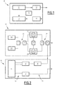
- the spectroscopy device 10 of the figure 1 is for example on board a satellite located in an earth orbit and carrying out observations of the Earth, or of another planet, and in particular of a layer of atmosphere of thickness equal for example to 15 km.
- the spectroscopy device 10 makes it possible to study a target material in this layer of atmosphere.
- the targeted material is for example a gas composed of several elementary gases such as, for example, CO 2 , H 2 O or CH 4 .
- Each elementary gas is able to absorb a light wave of a determined frequency with an absorption coefficient known a priori.
- the spectroscopy device 10 makes it possible, for example, to determine the densities of the elementary gases contained in the target gas by emitting a light signal towards the target gas and by analyzing a signal reflected by this gas, or absorbed by it and reflected by a gas. bottom surface.
- the spectroscopy device 10 is on board another space or land vehicle, or even an aircraft.
- the spectroscopy device 10 is arranged in a fixed manner, for example on the earth's surface.
- the spectroscopy device 10 also makes it possible to study a targeted material placed in any medium other than the atmosphere, such as for example the underwater or underground environment.
- the spectroscopy device 10 comprises a generation module 12, a transmission module 14, a reception module 15, a post-processing module 16 and a control module 18.
- the generation module 12 is able to form a transmission signal and a reference signal intended respectively for the transmission module 14 and for the post-processing module 16.
- the transmission module 14 is a transmission telescope known per se which is able to receive the transmission signals coming from the generation module 12 and to transmit them to the target material.
- the reception module 15 is a reception telescope also known per se which is able to receive response signals corresponding to the emission signals emitted by the emission module 14 and reflected by the targeted material or another material.
- the telescopes of the transmission 14 and reception 15 modules are in the form of a single component.
- the post-processing module 16 is able to receive the initial reference signals generated by the generation module 12 and the response signals received by the reception module 15 and to analyze these signals to determine the precise composition of the target material.
- the control module 18 makes it possible to control the operation of all the modules of the spectroscopy device 10.
- the control module 18 is for example connected to a central computer (not shown) of the satellite from which it is controlled.
- the generation module 12 and the post-processing module 16 will now be explained in more detail with reference to the figure 2 .
- the generation module 12 comprises two laser sources 20A, 20B, two optical paths 21, 22 connected to the laser sources 20A, 20B by upstream guide means 23 and to the emission 14 and post-processing modules 16 by means of downstream guidance 24, and an electronic device 25 for managing the optical channels 21, 22.
- Each laser source 20A, 20B is able to generate a laser signal at a predetermined wavelength, designated respectively by ⁇ A and ⁇ B.
- the wavelength ⁇ A is different from the wavelength ⁇ B.
- These predetermined wavelengths ⁇ A , ⁇ B are for example chosen as a function of the physical characteristics of the target material.
- the upstream guide means 23 comprise an upstream mixer 31 and an upstream separator 32 connected successively by waveguides, between the laser sources 20A, 20B on one side and the optical channels 21, 22 on the other.
- the upstream mixer 31 is able to mix the laser signals generated by the different laser sources 20A, 20B to form a complex signal at its output.
- the upstream splitter 32 is able to divide each complex signal formed by the upstream mixer 31 into two equal parts intended for the two optical channels 21, 22. Subsequently, each of these parts will be designated indifferently by the term “complex signal”.
- the optical channel 21, hereinafter referred to as the first optical channel, comprises a first modulator 41 capable of modulating the complex signal passing through this channel 21 to form a first modulated signal.
- the first modulator 41 is for example an electro-optical modulator known per se making it possible to generate a frequency comb by modulating the complex signal corresponding to a first modulation frequency F 1 equal for example to 1 GHz. This frequency comb is then included in the first modulated signal.
- the optical channel 22 hereinafter referred to as the second optical channel, comprises a second modulator 42 capable of modulating the complex signal passing through this channel 22 to form a second modulated signal.
- the second modulator 42 is for example an electro-optical modulator known per se making it possible to generate a frequency comb by modulating the complex signal corresponding to a second modulation frequency F 2 equal for example to F 1 +100 kHz. This frequency comb is then included in the second modulated signal.
- the electronic management device 25 makes it possible to control the operation of the modulators 41 and 42 according to techniques known per se. More particularly, the electronic device 25 is able to generate a radiofrequency signal of frequency F 1 controlling the operation of the first modulator 41 and a radiofrequency signal of frequency F 2 controlling the operation of the second modulator 42.
- the downstream guide means 24 comprise a downstream mixer 48 and a downstream separator 49 connected by waveguides, successively between the optical channels 21, 22 on one side and the emission 14 and post-processing 16 modules of the other.
- the downstream mixer 48 makes it possible to form a signal composed of the first modulated signal originating from the first optical channel 21 and the second modulated signal originating from the second optical channel 22.
- the downstream mixer 48 thus makes the combs generated by these combs beat together. different channels and then generates an interferogram.
- the downstream separator 49 makes it possible to separate the compound signal coming from the downstream mixer 48 into a low part and a high part, for example in a proportion of 10%: 90%.
- the weak part forms the reference signal intended for the post-processing module 16 and the strong part forms the transmission signal intended for the transmission module 14.
- Each of the reference signal and of the transmission signal then comprises an interferogram.
- the post-processing module 16 comprises a main filter 51, a complementary filter 52, upstream guide means 53, downstream guide means 54 and a processing unit 55.
- the upstream guide means 53 have waveguides connecting the main 51 and complementary 52 filters respectively to the reception 15 and generation 12 modules.
- the upstream guide means 53 make it possible to transmit each response signal from the reception module 15 to the main filter 51 and each reference signal from the generation module 12 to the complementary filter 52.
- the upstream guide means 53 comprise a retarder 56 arranged in the waveguides between the generation module 12 and the complementary filter 52. This retarder makes it possible to delay the transmission of the reference signal. relative to the transmit signal in order to synchronize this reference signal with the corresponding response signal.
- the main filter 51 is able to extract from the corresponding response signal elementary signals having different wavelengths.
- the main filter 51 is able to extract from each response signal received two elementary signals, namely an elementary signal of wavelength ⁇ A and an elementary signal of wavelength ⁇ B.
- the complementary filter 52 is able to extract from each reference signal two elementary signals, namely an elementary signal of wavelength ⁇ A and an elementary signal of wavelength ⁇ B.
- the downstream guide means 54 have waveguides connecting the filters 51, 52 to the processing unit 55. These waveguides form, for each filter 51, 52, a separate optical transmission path for each elementary signal issued. of the corresponding filter.
- these waveguides form optical transmission channels for each filter 51, 52.
- the processing unit 55 is able to receive all of the elementary signals transmitted via the downstream guide means 54 to determine the precise composition of the target material at several wavelengths. This is done by comparing in particular the spectra, calculated by Fourier transforms, of the interferograms contained in the elementary signals originating from the reference signal and in the reception signal.
- the target material is determined and the transmit 14 and receive 15 modules are configured to respectively transmit a transmit signal to that material and receive a response signal reflected from that material.
- control module 18 controls the generation of a transmission signal by the generation module 12.
- the generation module 12 then generates a transmission signal intended for the transmission module 14 and a reference signal intended for the post-processing module 16.
- This step 120 comprises several sub-steps.
- the two laser sources 20A, 20B generate two laser signals at wavelengths ⁇ A and ⁇ B.
- the upstream mixer 31 mixes the two laser signals generated to form a complex signal. This complex signal is then divided into two equal parts by the upstream separator 32.
- the complex signal passing through the first optical channel 21 is modulated at the first modulation frequency F 1 .
- the complex signal passing through the second optical channel 21 is modulated at the second modulation frequency F 2 .
- the downstream mixer 48 mixes the modulated signals coming from the optical channels 21, 22 and the downstream splitter 49 divides the signal coming from the mixer 48 to form a transmission signal and a reference signal.
- the emission module 15 transmits the emission signal to the targeted material.
- the reception module 15 receives a response signal corresponding to the transmission signal reflected by the targeted material.
- the post-processing module 16 analyzes the response signal and the reference signal to determine the precise composition of the target material.
- step 150 comprises several sub-steps.
- the main filter 51 receives the response signal received by the reception module 15 and extracts therefrom two elementary signals at wavelengths ⁇ A and ⁇ B.
- the complementary filter 52 receives the delayed reference signal, and extracts therefrom two elementary signals at wavelengths ⁇ A and ⁇ B.
- the main 51 and complementary 52 filters transmit all of the elementary signals to the processing unit which then analyzes them to determine the precise composition of the target material.
- the spectroscopy device and the spectroscopy method implemented by this device make it possible to implement a more complete analysis of the targeted material by simultaneously using spectroscopy at several wavelengths. It can then be seen that this makes it possible to increase the quality of the spectroscopy for various targeted materials.
- the invention is not limited to the architecture of the spectroscopy device described above.
- any known architecture further integrating several laser sources at different wavelengths in accordance with the invention can be used to implement the invention.
- downstream mixer 48 it is possible to completely suppress the transmission of a reference signal to the post-processing module 16. In this case, the beating of the two combs generated at different frequencies in the transmit signal, is sufficient to determine the precise composition of the target material.
- the main filter and possibly the complementary filter must be adapted to extract as many elementary signals at different wavelengths as laser sources.
Landscapes
- Physics & Mathematics (AREA)
- Spectroscopy & Molecular Physics (AREA)
- General Physics & Mathematics (AREA)
- Engineering & Computer Science (AREA)
- Health & Medical Sciences (AREA)
- Analytical Chemistry (AREA)
- Biochemistry (AREA)
- Pathology (AREA)
- Immunology (AREA)
- General Health & Medical Sciences (AREA)
- Life Sciences & Earth Sciences (AREA)
- Chemical & Material Sciences (AREA)
- Computer Networks & Wireless Communication (AREA)
- Remote Sensing (AREA)
- Radar, Positioning & Navigation (AREA)
- Electromagnetism (AREA)
- Optics & Photonics (AREA)
- Toxicology (AREA)
- Investigating Or Analysing Materials By Optical Means (AREA)
Claims (9)
- Vorrichtung (10) für Telespektroskopie vom Typ LIDAR, Folgendes umfassend:- ein Modul für das Erzeugen (12) eines Emissionssignals;- ein Modul für die Emission (14) des Emissionssignals zu einer Zielmaterie;- ein Modul für den Empfang (15) eines Antwortsignals, dem von der Zielmaterie reflektierten Emissionssignal entsprechend;- ein Modul für die Nachbehandlung (16) des Antwortsignals zum Bestimmen einer Zusammensetzung der Zielmaterie;wobei die Vorrichtung (10) dadurch gekennzeichnet ist, dass das Modul für die Erzeugung (12) Folgendes umfasst:- wenigstens zwei Laserquellen (20A, 20B), wobei jede Laserquelle (20A, 20B) in der Lage ist, ein Lasersignal mit einer vorher festgelegten Wellenlänge (λA; λB) zu erzeugen, die sich von der Wellenlänge der anderen oder jeder anderen Laserquelle (20A, 20B) unterscheidet;- ein vorgelagerter Vermischer (31), in der Lage, die von den verschiedenen Laserquellen (20A, 20B) erzeugten Lasersignale zu mischen, um ein komplexes Signal zu bilden;- einen ersten Modulator (41), in der Lage, das komplexe Signal mit einer ersten Modulationsfrequenz (F1) zu modulieren, um das Emissionssignal zu bilden; und- einen zweiten Modulator (42), in der Lage, das komplexe Signal mit einer zweiten Modulationsfrequenz (F2) zu modulieren, die sich von der ersten Modulationsfrequenz (F1) unterscheidet,in welcher das Modul für die Erzeugung (12) weiter einen nachgelagerten Vermischer (48) umfasst, in der Lage, das von dem ersten Modulator (41) modulierte komplexe Signal und das von dem zweiten Modulator (42) modulierte komplexe Signal zu mischen, um das Emissionssignal zu bilden.
- Vorrichtung (10) gemäß Anspruch 1, in welchem das Modul für die Nachbehandlung (16) einen Hauptfilter (51) umfasst, in der Lage, das Antwortsignal zu extrahieren, empfangen aus den elementaren Signalen, den verschiedenen vorher festgelegten Wellenlängen (λA; λB) entsprechend.
- Vorrichtung (10) nach Anspruch 1 oder 2, in welcher das Modul für die Erzeugung (12) weiter einen Separator (32, 49) des komplexen Signals oder des Emissionssignals umfasst, um ein Referenzsignal zu bilden, bestimmt für das Modul für die Nachbehandlung (16).
- Vorrichtung (10) nach Anspruch 3, in welcher das Modul für die Nachbehandlung (16) weiter einen komplementären Filter (52) umfasst, in der Lage, aus dem Referenzsignal die elementaren Signale entsprechend den verschiedenen vorher festgelegten Wellenlängen (λA, λB) zu extrahieren.
- Vorrichtung (10) nach einem der vorhergehenden Ansprüche, in welcher die erste Modulierungsfrequenz (F1) gemäß der physischen Merkmale der Zielmaterie ausgewählt wird.
- Vorrichtung (10) nach einem der vorhergehenden Ansprüche, in welcher die vorher festgelegten Wellenlängen (λA, λB) gemäß der physischen Merkmale der Zielmaterie ausgewählt sind.
- Verfahren für Telespektroskopie, umfassend die folgenden Schritte:- Erzeugen (120) eines Emissionssignals;- Emission (130) des Emissionssignals zu einer Zielmaterie;- Empfangen (140) eines Antwortsignals, dem von der Zielmaterie reflektierten Emissionssignal entsprechend;- Analyse (150) des Antwortsignals zum Bestimmen einer Zusammensetzung der Zielmaterie;wobei das Verfahren dadurch gekennzeichnet ist, dass der Schritt der Erzeugung (120) des Emissionssignals die folgenden Unterschritte umfasst:- Erzeugen (121) von wenigstens zwei Lasersignalen mit verschiedenen vorher festgelegten Wellenlängen (λA, λB);- Mischen (122) der erzeugten Lasersignale, um ein komplexes Signal zu bilden;- Modulation (123) des komplexen Signals bei einer ersten Modulationsfrequenz (F1), um das Emissionssignal zu bilden;- Modulation (124) des komplexen Signals mit einer zweiten Modulationsfrequenz (F2), die sich von der ersten Modulationsfrequenz (F1) unterscheidet, um das Emissionssignal zu bilden; und- Mischen (125) der komplexen Signale, moduliert mit der ersten und der zweiten Modulationsfrequenz, um das Emissionssignal zu bilden.
- Verfahren nach Anspruch 7, in welchem der Schritt der Analyse (150) des Antwortsignals den folgenden Unterschritt umfasst:- Extraktion (151) des empfangenen Antwortsignals aus den elementaren Signalen entsprechend den verschiedenen vorher festgelegten Wellenlängen (λA, λB).
- Verfahren nach Anspruch 8, in welchem der Schritt der Erzeugung (120) des Emissionssignals weiter den folgenden Unterschritt umfasst:- Trennung (125) des Emissionssignals, um ein Referenzsignal zu bilden; und- in welchem der Schritt der Analyse (150) des Antwortsignals weiter den folgenden Unterschritt umfasst:- Extraktion (152) des Referenzsignals aus den elementaren Signalen, den verschiedenen vorher festgelegten Wellenlängen (λA, λB) entsprechend.
Applications Claiming Priority (1)
| Application Number | Priority Date | Filing Date | Title |
|---|---|---|---|
| FR1754568A FR3066862A1 (fr) | 2017-05-23 | 2017-05-23 | Dispositif de spectroscopie a distance a une source laser complexe et procede de spectroscopie a distance associe |
Publications (2)
| Publication Number | Publication Date |
|---|---|
| EP3407091A1 EP3407091A1 (de) | 2018-11-28 |
| EP3407091B1 true EP3407091B1 (de) | 2021-07-28 |
Family
ID=60627681
Family Applications (1)
| Application Number | Title | Priority Date | Filing Date |
|---|---|---|---|
| EP18173585.3A Active EP3407091B1 (de) | 2017-05-23 | 2018-05-22 | Telespektroskopievorrichtung mit einer komplexen laserquelle, und entsprechendes telespektroskopieverfahren |
Country Status (4)
| Country | Link |
|---|---|
| US (1) | US10466105B2 (de) |
| EP (1) | EP3407091B1 (de) |
| CN (1) | CN108931485B (de) |
| FR (1) | FR3066862A1 (de) |
Families Citing this family (1)
| Publication number | Priority date | Publication date | Assignee | Title |
|---|---|---|---|---|
| CN111190160B (zh) * | 2020-01-08 | 2022-02-15 | 南京航空航天大学 | 微波光子多波段雷达探测方法及微波光子多波段雷达 |
Family Cites Families (17)
| Publication number | Priority date | Publication date | Assignee | Title |
|---|---|---|---|---|
| JP4127649B2 (ja) * | 2003-01-14 | 2008-07-30 | 三菱電機株式会社 | コヒーレントレーザレーダ装置 |
| US7009170B2 (en) * | 2003-06-26 | 2006-03-07 | Itt Manufacturing Enterprises, Inc. | Active remote sensing using a simultaneous spectral sampling technique |
| JP4657956B2 (ja) * | 2006-03-14 | 2011-03-23 | 三菱電機株式会社 | 差分吸収ライダ装置 |
| US7969576B1 (en) * | 2007-03-23 | 2011-06-28 | The Regents Of The University Of California | Optical sensing based on wavelength modulation spectroscopy |
| JP5764566B2 (ja) * | 2009-10-02 | 2015-08-19 | イムラ アメリカ インコーポレイテッド | モード同期レーザによる光信号処理 |
| US9310487B2 (en) * | 2011-12-21 | 2016-04-12 | Mitsubishi Electric Corporation | Lidar with a plurality of laser light rays having different wavelengths |
| US20160291137A1 (en) * | 2013-12-10 | 2016-10-06 | Mitsubishi Electric Corporation | Laser radar device |
| US9903808B2 (en) * | 2014-01-17 | 2018-02-27 | The United States Of America, As Represented By The Secretary Of Commerce | Variable-frequency optical combs, heterodyne sensor, and process for performing spectroscopy |
| US9086374B1 (en) * | 2014-04-25 | 2015-07-21 | Joseph R. Demers | Terahertz spectrometer with phase modulation and method |
| KR102055047B1 (ko) * | 2014-08-01 | 2019-12-11 | 뉴포트 코포레이션 | 광학 기반 전기 신호 동시 일관 수신 시스템 및 방법 |
| KR101603909B1 (ko) * | 2014-10-02 | 2016-03-16 | 광주과학기술원 | 위상잡음 보상 방법을 이용한 광혼합 방식의 연속파 테라헤르츠 발생 및 검출 장치 |
| FR3027116B1 (fr) * | 2014-10-08 | 2016-12-09 | Centre Nat D'etudes Spatiales (Cnes) | Dispositif de spectroscopie a distance de type lidar |
| US9429473B2 (en) * | 2014-10-16 | 2016-08-30 | Joseph R. Demers | Terahertz spectrometer and method for reducing photomixing interference pattern |
| DE112016002209T5 (de) * | 2015-06-23 | 2018-03-01 | Olympus Corporation | Bilderlangungsvorrichtung und Bilderlangungsverfahren |
| FR3039331B1 (fr) * | 2015-07-22 | 2017-08-25 | Centre Nat D'etudes Spatiales (Cnes) | Procede de spectroscopie a distance, produit programme d'ordinateur et dispositif de spectroscopie associes |
| CN105589074A (zh) * | 2015-11-27 | 2016-05-18 | 中国人民解放军国防科学技术大学 | 基于飞秒光梳同步锁频的多波长干涉实时绝对测距装置 |
| AU2017382218B2 (en) * | 2016-12-21 | 2023-05-11 | Acucela Inc. | Miniaturized mobile, low cost optical coherence tomography system for home based ophthalmic applications |
-
2017
- 2017-05-23 FR FR1754568A patent/FR3066862A1/fr active Pending
-
2018
- 2018-05-22 US US15/986,445 patent/US10466105B2/en active Active
- 2018-05-22 CN CN201810497659.0A patent/CN108931485B/zh active Active
- 2018-05-22 EP EP18173585.3A patent/EP3407091B1/de active Active
Also Published As
| Publication number | Publication date |
|---|---|
| EP3407091A1 (de) | 2018-11-28 |
| CN108931485B (zh) | 2023-02-10 |
| CN108931485A (zh) | 2018-12-04 |
| US20180340829A1 (en) | 2018-11-29 |
| FR3066862A1 (fr) | 2018-11-30 |
| US10466105B2 (en) | 2019-11-05 |
Similar Documents
| Publication | Publication Date | Title |
|---|---|---|
| EP0120775B1 (de) | Entfernungs- und Dopplermessung mittels einer Laseranordnung mit Pulszeitraffung | |
| EP3504559A1 (de) | Verfahren zur verarbeitung eines signals aus kohärentem lidar und zugehöriges lidar-system | |
| EP4256291B1 (de) | Vorrichtung zur breitbandigen spektralanalyse eines signals | |
| FR3061309A1 (fr) | Methode de traitement d'un signal issu d'un lidar coherent pour reduire le bruit et systeme lidar associe | |
| EP3714233A1 (de) | Vorrichtung und verfahren zur interaktion zwischen einem agilen laserstrahl und einem hyperfeinen energieübergang einer chemischen spezies | |
| EP1361419B1 (de) | Vorrichtung und Verfahren zur Messung von ultrakurzen Lichtimpulsen | |
| EP3407091B1 (de) | Telespektroskopievorrichtung mit einer komplexen laserquelle, und entsprechendes telespektroskopieverfahren | |
| EP2260540B1 (de) | Optische vorrichtung zur anwendung einer echtzeitverzögerung auf ein elektrisches funksignal und ihre verwendung bei der formung von sende- und empfangsstrahlen mit einer aktivantenne | |
| EP2510392A1 (de) | Vorrichtung zur kompensation von temporärer streuung bei der erzeugung von ultrakurzen lichtimpulsen | |
| EP3407087B1 (de) | Erzeugungsverfahren von frequenzkämmen, entsprechendes erzeugungsmodul, telespektroskopieverfahren und entsprechende spektroskopievorrichtung | |
| FR3039331A1 (fr) | Procede de spectroscopie a distance, produit programme d'ordinateur et dispositif de spectroscopie associes | |
| FR3099587A1 (fr) | Methode d'imagerie par un lidar coherent et lidar associe | |
| FR3027116A1 (fr) | Dispositif de spectroscopie a distance de type lidar | |
| EP2575311B1 (de) | System zur Demodulation | |
| FR3019691A1 (fr) | Systeme laser asservi en longueur d'onde | |
| EP3977158B1 (de) | Lidar-system mit einem interferenziellen diffraktiven element und lidar-abbildungsverfahren | |
| FR2973885A1 (fr) | Procede et dispositif de suppression optique coherente de la diaphonie optique. | |
| EP0871304A1 (de) | Verfahren und Vorrichtung zur Formung eines optischen binären Signales | |
| EP4078217B1 (de) | Lidar-system mit zwei diffraktiven komponenten | |
| EP4554113A1 (de) | Photonische vorrichtung und verfahren zur übertragung und/oder frequenzumsetzung von hochfrequenzsignalen eines telekommunikationssatelliten | |
| EP2470916B1 (de) | Messung der fahrgeschwindigkeit eines mobilen elements | |
| FR3134458A1 (fr) | Système de positionnement à segments de câble rayonnant | |
| WO2024047296A1 (fr) | Systeme lidar pour mesures velocimetriques | |
| FR3075521A1 (fr) | Systeme de communication comprenant un dispositif de compensation a etoile artificielle |
Legal Events
| Date | Code | Title | Description |
|---|---|---|---|
| PUAI | Public reference made under article 153(3) epc to a published international application that has entered the european phase |
Free format text: ORIGINAL CODE: 0009012 |
|
| STAA | Information on the status of an ep patent application or granted ep patent |
Free format text: STATUS: THE APPLICATION HAS BEEN PUBLISHED |
|
| AK | Designated contracting states |
Kind code of ref document: A1 Designated state(s): AL AT BE BG CH CY CZ DE DK EE ES FI FR GB GR HR HU IE IS IT LI LT LU LV MC MK MT NL NO PL PT RO RS SE SI SK SM TR |
|
| AX | Request for extension of the european patent |
Extension state: BA ME |
|
| STAA | Information on the status of an ep patent application or granted ep patent |
Free format text: STATUS: REQUEST FOR EXAMINATION WAS MADE |
|
| 17P | Request for examination filed |
Effective date: 20190410 |
|
| RBV | Designated contracting states (corrected) |
Designated state(s): AL AT BE BG CH CY CZ DE DK EE ES FI FR GB GR HR HU IE IS IT LI LT LU LV MC MK MT NL NO PL PT RO RS SE SI SK SM TR |
|
| STAA | Information on the status of an ep patent application or granted ep patent |
Free format text: STATUS: EXAMINATION IS IN PROGRESS |
|
| 17Q | First examination report despatched |
Effective date: 20210304 |
|
| GRAP | Despatch of communication of intention to grant a patent |
Free format text: ORIGINAL CODE: EPIDOSNIGR1 |
|
| STAA | Information on the status of an ep patent application or granted ep patent |
Free format text: STATUS: GRANT OF PATENT IS INTENDED |
|
| INTG | Intention to grant announced |
Effective date: 20210423 |
|
| GRAS | Grant fee paid |
Free format text: ORIGINAL CODE: EPIDOSNIGR3 |
|
| GRAA | (expected) grant |
Free format text: ORIGINAL CODE: 0009210 |
|
| STAA | Information on the status of an ep patent application or granted ep patent |
Free format text: STATUS: THE PATENT HAS BEEN GRANTED |
|
| AK | Designated contracting states |
Kind code of ref document: B1 Designated state(s): AL AT BE BG CH CY CZ DE DK EE ES FI FR GB GR HR HU IE IS IT LI LT LU LV MC MK MT NL NO PL PT RO RS SE SI SK SM TR |
|
| REG | Reference to a national code |
Ref country code: GB Ref legal event code: FG4D Free format text: NOT ENGLISH |
|
| REG | Reference to a national code |
Ref country code: CH Ref legal event code: EP |
|
| REG | Reference to a national code |
Ref country code: DE Ref legal event code: R096 Ref document number: 602018020669 Country of ref document: DE |
|
| REG | Reference to a national code |
Ref country code: AT Ref legal event code: REF Ref document number: 1415192 Country of ref document: AT Kind code of ref document: T Effective date: 20210815 |
|
| REG | Reference to a national code |
Ref country code: IE Ref legal event code: FG4D Free format text: LANGUAGE OF EP DOCUMENT: FRENCH |
|
| REG | Reference to a national code |
Ref country code: LT Ref legal event code: MG9D |
|
| REG | Reference to a national code |
Ref country code: NL Ref legal event code: MP Effective date: 20210728 |
|
| REG | Reference to a national code |
Ref country code: AT Ref legal event code: MK05 Ref document number: 1415192 Country of ref document: AT Kind code of ref document: T Effective date: 20210728 |
|
| PG25 | Lapsed in a contracting state [announced via postgrant information from national office to epo] |
Ref country code: RS Free format text: LAPSE BECAUSE OF FAILURE TO SUBMIT A TRANSLATION OF THE DESCRIPTION OR TO PAY THE FEE WITHIN THE PRESCRIBED TIME-LIMIT Effective date: 20210728 Ref country code: SE Free format text: LAPSE BECAUSE OF FAILURE TO SUBMIT A TRANSLATION OF THE DESCRIPTION OR TO PAY THE FEE WITHIN THE PRESCRIBED TIME-LIMIT Effective date: 20210728 Ref country code: HR Free format text: LAPSE BECAUSE OF FAILURE TO SUBMIT A TRANSLATION OF THE DESCRIPTION OR TO PAY THE FEE WITHIN THE PRESCRIBED TIME-LIMIT Effective date: 20210728 Ref country code: FI Free format text: LAPSE BECAUSE OF FAILURE TO SUBMIT A TRANSLATION OF THE DESCRIPTION OR TO PAY THE FEE WITHIN THE PRESCRIBED TIME-LIMIT Effective date: 20210728 Ref country code: ES Free format text: LAPSE BECAUSE OF FAILURE TO SUBMIT A TRANSLATION OF THE DESCRIPTION OR TO PAY THE FEE WITHIN THE PRESCRIBED TIME-LIMIT Effective date: 20210728 Ref country code: PT Free format text: LAPSE BECAUSE OF FAILURE TO SUBMIT A TRANSLATION OF THE DESCRIPTION OR TO PAY THE FEE WITHIN THE PRESCRIBED TIME-LIMIT Effective date: 20211129 Ref country code: NL Free format text: LAPSE BECAUSE OF FAILURE TO SUBMIT A TRANSLATION OF THE DESCRIPTION OR TO PAY THE FEE WITHIN THE PRESCRIBED TIME-LIMIT Effective date: 20210728 Ref country code: NO Free format text: LAPSE BECAUSE OF FAILURE TO SUBMIT A TRANSLATION OF THE DESCRIPTION OR TO PAY THE FEE WITHIN THE PRESCRIBED TIME-LIMIT Effective date: 20211028 Ref country code: LT Free format text: LAPSE BECAUSE OF FAILURE TO SUBMIT A TRANSLATION OF THE DESCRIPTION OR TO PAY THE FEE WITHIN THE PRESCRIBED TIME-LIMIT Effective date: 20210728 Ref country code: AT Free format text: LAPSE BECAUSE OF FAILURE TO SUBMIT A TRANSLATION OF THE DESCRIPTION OR TO PAY THE FEE WITHIN THE PRESCRIBED TIME-LIMIT Effective date: 20210728 Ref country code: BG Free format text: LAPSE BECAUSE OF FAILURE TO SUBMIT A TRANSLATION OF THE DESCRIPTION OR TO PAY THE FEE WITHIN THE PRESCRIBED TIME-LIMIT Effective date: 20211028 |
|
| PG25 | Lapsed in a contracting state [announced via postgrant information from national office to epo] |
Ref country code: PL Free format text: LAPSE BECAUSE OF FAILURE TO SUBMIT A TRANSLATION OF THE DESCRIPTION OR TO PAY THE FEE WITHIN THE PRESCRIBED TIME-LIMIT Effective date: 20210728 Ref country code: LV Free format text: LAPSE BECAUSE OF FAILURE TO SUBMIT A TRANSLATION OF THE DESCRIPTION OR TO PAY THE FEE WITHIN THE PRESCRIBED TIME-LIMIT Effective date: 20210728 Ref country code: GR Free format text: LAPSE BECAUSE OF FAILURE TO SUBMIT A TRANSLATION OF THE DESCRIPTION OR TO PAY THE FEE WITHIN THE PRESCRIBED TIME-LIMIT Effective date: 20211029 |
|
| PG25 | Lapsed in a contracting state [announced via postgrant information from national office to epo] |
Ref country code: DK Free format text: LAPSE BECAUSE OF FAILURE TO SUBMIT A TRANSLATION OF THE DESCRIPTION OR TO PAY THE FEE WITHIN THE PRESCRIBED TIME-LIMIT Effective date: 20210728 |
|
| REG | Reference to a national code |
Ref country code: DE Ref legal event code: R097 Ref document number: 602018020669 Country of ref document: DE |
|
| PG25 | Lapsed in a contracting state [announced via postgrant information from national office to epo] |
Ref country code: SM Free format text: LAPSE BECAUSE OF FAILURE TO SUBMIT A TRANSLATION OF THE DESCRIPTION OR TO PAY THE FEE WITHIN THE PRESCRIBED TIME-LIMIT Effective date: 20210728 Ref country code: SK Free format text: LAPSE BECAUSE OF FAILURE TO SUBMIT A TRANSLATION OF THE DESCRIPTION OR TO PAY THE FEE WITHIN THE PRESCRIBED TIME-LIMIT Effective date: 20210728 Ref country code: RO Free format text: LAPSE BECAUSE OF FAILURE TO SUBMIT A TRANSLATION OF THE DESCRIPTION OR TO PAY THE FEE WITHIN THE PRESCRIBED TIME-LIMIT Effective date: 20210728 Ref country code: EE Free format text: LAPSE BECAUSE OF FAILURE TO SUBMIT A TRANSLATION OF THE DESCRIPTION OR TO PAY THE FEE WITHIN THE PRESCRIBED TIME-LIMIT Effective date: 20210728 Ref country code: CZ Free format text: LAPSE BECAUSE OF FAILURE TO SUBMIT A TRANSLATION OF THE DESCRIPTION OR TO PAY THE FEE WITHIN THE PRESCRIBED TIME-LIMIT Effective date: 20210728 Ref country code: AL Free format text: LAPSE BECAUSE OF FAILURE TO SUBMIT A TRANSLATION OF THE DESCRIPTION OR TO PAY THE FEE WITHIN THE PRESCRIBED TIME-LIMIT Effective date: 20210728 |
|
| PLBE | No opposition filed within time limit |
Free format text: ORIGINAL CODE: 0009261 |
|
| STAA | Information on the status of an ep patent application or granted ep patent |
Free format text: STATUS: NO OPPOSITION FILED WITHIN TIME LIMIT |
|
| 26N | No opposition filed |
Effective date: 20220429 |
|
| PG25 | Lapsed in a contracting state [announced via postgrant information from national office to epo] |
Ref country code: IT Free format text: LAPSE BECAUSE OF FAILURE TO SUBMIT A TRANSLATION OF THE DESCRIPTION OR TO PAY THE FEE WITHIN THE PRESCRIBED TIME-LIMIT Effective date: 20210728 |
|
| REG | Reference to a national code |
Ref country code: DE Ref legal event code: R119 Ref document number: 602018020669 Country of ref document: DE |
|
| REG | Reference to a national code |
Ref country code: CH Ref legal event code: PL |
|
| REG | Reference to a national code |
Ref country code: BE Ref legal event code: MM Effective date: 20220531 |
|
| GBPC | Gb: european patent ceased through non-payment of renewal fee |
Effective date: 20220522 |
|
| PG25 | Lapsed in a contracting state [announced via postgrant information from national office to epo] |
Ref country code: MC Free format text: LAPSE BECAUSE OF FAILURE TO SUBMIT A TRANSLATION OF THE DESCRIPTION OR TO PAY THE FEE WITHIN THE PRESCRIBED TIME-LIMIT Effective date: 20210728 Ref country code: LU Free format text: LAPSE BECAUSE OF NON-PAYMENT OF DUE FEES Effective date: 20220522 Ref country code: LI Free format text: LAPSE BECAUSE OF NON-PAYMENT OF DUE FEES Effective date: 20220531 Ref country code: CH Free format text: LAPSE BECAUSE OF NON-PAYMENT OF DUE FEES Effective date: 20220531 |
|
| PG25 | Lapsed in a contracting state [announced via postgrant information from national office to epo] |
Ref country code: IE Free format text: LAPSE BECAUSE OF NON-PAYMENT OF DUE FEES Effective date: 20220522 |
|
| PG25 | Lapsed in a contracting state [announced via postgrant information from national office to epo] |
Ref country code: GB Free format text: LAPSE BECAUSE OF NON-PAYMENT OF DUE FEES Effective date: 20220522 Ref country code: DE Free format text: LAPSE BECAUSE OF NON-PAYMENT OF DUE FEES Effective date: 20221201 Ref country code: BE Free format text: LAPSE BECAUSE OF NON-PAYMENT OF DUE FEES Effective date: 20220531 |
|
| PG25 | Lapsed in a contracting state [announced via postgrant information from national office to epo] |
Ref country code: HU Free format text: LAPSE BECAUSE OF FAILURE TO SUBMIT A TRANSLATION OF THE DESCRIPTION OR TO PAY THE FEE WITHIN THE PRESCRIBED TIME-LIMIT; INVALID AB INITIO Effective date: 20180522 |
|
| PG25 | Lapsed in a contracting state [announced via postgrant information from national office to epo] |
Ref country code: MK Free format text: LAPSE BECAUSE OF FAILURE TO SUBMIT A TRANSLATION OF THE DESCRIPTION OR TO PAY THE FEE WITHIN THE PRESCRIBED TIME-LIMIT Effective date: 20210728 Ref country code: CY Free format text: LAPSE BECAUSE OF FAILURE TO SUBMIT A TRANSLATION OF THE DESCRIPTION OR TO PAY THE FEE WITHIN THE PRESCRIBED TIME-LIMIT Effective date: 20210728 |
|
| PG25 | Lapsed in a contracting state [announced via postgrant information from national office to epo] |
Ref country code: MT Free format text: LAPSE BECAUSE OF FAILURE TO SUBMIT A TRANSLATION OF THE DESCRIPTION OR TO PAY THE FEE WITHIN THE PRESCRIBED TIME-LIMIT Effective date: 20210728 |
|
| PG25 | Lapsed in a contracting state [announced via postgrant information from national office to epo] |
Ref country code: TR Free format text: LAPSE BECAUSE OF FAILURE TO SUBMIT A TRANSLATION OF THE DESCRIPTION OR TO PAY THE FEE WITHIN THE PRESCRIBED TIME-LIMIT Effective date: 20210728 |
|
| PGFP | Annual fee paid to national office [announced via postgrant information from national office to epo] |
Ref country code: FR Payment date: 20260330 Year of fee payment: 9 |