EP3407088A1 - Systems and methods for tracking location of movable target object - Google Patents
Systems and methods for tracking location of movable target object Download PDFInfo
- Publication number
- EP3407088A1 EP3407088A1 EP18179415.7A EP18179415A EP3407088A1 EP 3407088 A1 EP3407088 A1 EP 3407088A1 EP 18179415 A EP18179415 A EP 18179415A EP 3407088 A1 EP3407088 A1 EP 3407088A1
- Authority
- EP
- European Patent Office
- Prior art keywords
- target object
- camera
- pan
- software
- image
- Prior art date
- Legal status (The legal status is an assumption and is not a legal conclusion. Google has not performed a legal analysis and makes no representation as to the accuracy of the status listed.)
- Withdrawn
Links
- 238000000034 method Methods 0.000 title claims abstract description 94
- 230000008569 process Effects 0.000 claims abstract description 51
- 238000012545 processing Methods 0.000 claims abstract description 22
- 230000033001 locomotion Effects 0.000 claims description 54
- 230000007246 mechanism Effects 0.000 claims description 35
- 238000005259 measurement Methods 0.000 abstract description 42
- 230000009466 transformation Effects 0.000 abstract description 30
- 239000003550 marker Substances 0.000 abstract description 12
- 239000011159 matrix material Substances 0.000 description 26
- 230000004807 localization Effects 0.000 description 13
- 239000013598 vector Substances 0.000 description 10
- 238000012937 correction Methods 0.000 description 7
- 230000006870 function Effects 0.000 description 7
- 238000010586 diagram Methods 0.000 description 6
- 230000003287 optical effect Effects 0.000 description 5
- 230000005540 biological transmission Effects 0.000 description 4
- 239000012636 effector Substances 0.000 description 4
- 230000004044 response Effects 0.000 description 4
- 238000013519 translation Methods 0.000 description 3
- 230000004913 activation Effects 0.000 description 2
- 238000003709 image segmentation Methods 0.000 description 2
- 238000004519 manufacturing process Methods 0.000 description 2
- CWYNVVGOOAEACU-UHFFFAOYSA-N Fe2+ Chemical compound [Fe+2] CWYNVVGOOAEACU-UHFFFAOYSA-N 0.000 description 1
- 239000008186 active pharmaceutical agent Substances 0.000 description 1
- 238000013459 approach Methods 0.000 description 1
- 238000004364 calculation method Methods 0.000 description 1
- 230000008859 change Effects 0.000 description 1
- 230000008867 communication pathway Effects 0.000 description 1
- 238000004590 computer program Methods 0.000 description 1
- 230000001351 cycling effect Effects 0.000 description 1
- 238000006073 displacement reaction Methods 0.000 description 1
- 238000001914 filtration Methods 0.000 description 1
- 238000009432 framing Methods 0.000 description 1
- 238000003754 machining Methods 0.000 description 1
- 239000000463 material Substances 0.000 description 1
- 238000000691 measurement method Methods 0.000 description 1
- 238000012986 modification Methods 0.000 description 1
- 230000004048 modification Effects 0.000 description 1
- 230000011218 segmentation Effects 0.000 description 1
- 230000009897 systematic effect Effects 0.000 description 1
- 238000012546 transfer Methods 0.000 description 1
Images


Classifications
-
- G—PHYSICS
- G01—MEASURING; TESTING
- G01S—RADIO DIRECTION-FINDING; RADIO NAVIGATION; DETERMINING DISTANCE OR VELOCITY BY USE OF RADIO WAVES; LOCATING OR PRESENCE-DETECTING BY USE OF THE REFLECTION OR RERADIATION OF RADIO WAVES; ANALOGOUS ARRANGEMENTS USING OTHER WAVES
- G01S17/00—Systems using the reflection or reradiation of electromagnetic waves other than radio waves, e.g. lidar systems
- G01S17/88—Lidar systems specially adapted for specific applications
-
- G—PHYSICS
- G01—MEASURING; TESTING
- G01S—RADIO DIRECTION-FINDING; RADIO NAVIGATION; DETERMINING DISTANCE OR VELOCITY BY USE OF RADIO WAVES; LOCATING OR PRESENCE-DETECTING BY USE OF THE REFLECTION OR RERADIATION OF RADIO WAVES; ANALOGOUS ARRANGEMENTS USING OTHER WAVES
- G01S17/00—Systems using the reflection or reradiation of electromagnetic waves other than radio waves, e.g. lidar systems
- G01S17/02—Systems using the reflection of electromagnetic waves other than radio waves
- G01S17/06—Systems determining position data of a target
- G01S17/08—Systems determining position data of a target for measuring distance only
-
- G—PHYSICS
- G01—MEASURING; TESTING
- G01S—RADIO DIRECTION-FINDING; RADIO NAVIGATION; DETERMINING DISTANCE OR VELOCITY BY USE OF RADIO WAVES; LOCATING OR PRESENCE-DETECTING BY USE OF THE REFLECTION OR RERADIATION OF RADIO WAVES; ANALOGOUS ARRANGEMENTS USING OTHER WAVES
- G01S17/00—Systems using the reflection or reradiation of electromagnetic waves other than radio waves, e.g. lidar systems
- G01S17/02—Systems using the reflection of electromagnetic waves other than radio waves
- G01S17/06—Systems determining position data of a target
- G01S17/46—Indirect determination of position data
-
- G—PHYSICS
- G01—MEASURING; TESTING
- G01S—RADIO DIRECTION-FINDING; RADIO NAVIGATION; DETERMINING DISTANCE OR VELOCITY BY USE OF RADIO WAVES; LOCATING OR PRESENCE-DETECTING BY USE OF THE REFLECTION OR RERADIATION OF RADIO WAVES; ANALOGOUS ARRANGEMENTS USING OTHER WAVES
- G01S3/00—Direction-finders for determining the direction from which infrasonic, sonic, ultrasonic, or electromagnetic waves, or particle emission, not having a directional significance, are being received
- G01S3/78—Direction-finders for determining the direction from which infrasonic, sonic, ultrasonic, or electromagnetic waves, or particle emission, not having a directional significance, are being received using electromagnetic waves other than radio waves
- G01S3/782—Systems for determining direction or deviation from predetermined direction
- G01S3/785—Systems for determining direction or deviation from predetermined direction using adjustment of orientation of directivity characteristics of a detector or detector system to give a desired condition of signal derived from that detector or detector system
- G01S3/786—Systems for determining direction or deviation from predetermined direction using adjustment of orientation of directivity characteristics of a detector or detector system to give a desired condition of signal derived from that detector or detector system the desired condition being maintained automatically
- G01S3/7864—T.V. type tracking systems
-
- G—PHYSICS
- G01—MEASURING; TESTING
- G01S—RADIO DIRECTION-FINDING; RADIO NAVIGATION; DETERMINING DISTANCE OR VELOCITY BY USE OF RADIO WAVES; LOCATING OR PRESENCE-DETECTING BY USE OF THE REFLECTION OR RERADIATION OF RADIO WAVES; ANALOGOUS ARRANGEMENTS USING OTHER WAVES
- G01S5/00—Position-fixing by co-ordinating two or more direction or position line determinations; Position-fixing by co-ordinating two or more distance determinations
- G01S5/16—Position-fixing by co-ordinating two or more direction or position line determinations; Position-fixing by co-ordinating two or more distance determinations using electromagnetic waves other than radio waves
- G01S5/163—Determination of attitude
-
- G—PHYSICS
- G06—COMPUTING; CALCULATING OR COUNTING
- G06F—ELECTRIC DIGITAL DATA PROCESSING
- G06F17/00—Digital computing or data processing equipment or methods, specially adapted for specific functions
- G06F17/10—Complex mathematical operations
- G06F17/16—Matrix or vector computation, e.g. matrix-matrix or matrix-vector multiplication, matrix factorization
-
- G—PHYSICS
- G06—COMPUTING; CALCULATING OR COUNTING
- G06T—IMAGE DATA PROCESSING OR GENERATION, IN GENERAL
- G06T7/00—Image analysis
- G06T7/20—Analysis of motion
- G06T7/246—Analysis of motion using feature-based methods, e.g. the tracking of corners or segments
- G06T7/248—Analysis of motion using feature-based methods, e.g. the tracking of corners or segments involving reference images or patches
-
- H—ELECTRICITY
- H04—ELECTRIC COMMUNICATION TECHNIQUE
- H04N—PICTORIAL COMMUNICATION, e.g. TELEVISION
- H04N23/00—Cameras or camera modules comprising electronic image sensors; Control thereof
- H04N23/60—Control of cameras or camera modules
- H04N23/64—Computer-aided capture of images, e.g. transfer from script file into camera, check of taken image quality, advice or proposal for image composition or decision on when to take image
-
- H—ELECTRICITY
- H04—ELECTRIC COMMUNICATION TECHNIQUE
- H04N—PICTORIAL COMMUNICATION, e.g. TELEVISION
- H04N23/00—Cameras or camera modules comprising electronic image sensors; Control thereof
- H04N23/60—Control of cameras or camera modules
- H04N23/69—Control of means for changing angle of the field of view, e.g. optical zoom objectives or electronic zooming
-
- H—ELECTRICITY
- H04—ELECTRIC COMMUNICATION TECHNIQUE
- H04N—PICTORIAL COMMUNICATION, e.g. TELEVISION
- H04N7/00—Television systems
- H04N7/18—Closed-circuit television [CCTV] systems, i.e. systems in which the video signal is not broadcast
- H04N7/183—Closed-circuit television [CCTV] systems, i.e. systems in which the video signal is not broadcast for receiving images from a single remote source
-
- Y—GENERAL TAGGING OF NEW TECHNOLOGICAL DEVELOPMENTS; GENERAL TAGGING OF CROSS-SECTIONAL TECHNOLOGIES SPANNING OVER SEVERAL SECTIONS OF THE IPC; TECHNICAL SUBJECTS COVERED BY FORMER USPC CROSS-REFERENCE ART COLLECTIONS [XRACs] AND DIGESTS
- Y10—TECHNICAL SUBJECTS COVERED BY FORMER USPC
- Y10S—TECHNICAL SUBJECTS COVERED BY FORMER USPC CROSS-REFERENCE ART COLLECTIONS [XRACs] AND DIGESTS
- Y10S901/00—Robots
- Y10S901/46—Sensing device
Definitions
- This disclosure generally relates to systems and methods for tracking the locations of a movable target object (e.g., a crawler vehicle or other electro-mechanical machine that is guided by a computer program) as it moves relative to a workpiece or part.
- a movable target object e.g., a crawler vehicle or other electro-mechanical machine that is guided by a computer program
- Absolute motion tracking refers to tracking of position and/or orientation defined in a reference coordinate system, such as an airplane coordinate system.
- Known techniques for absolute motion tracking include optical motion capture, laser tracking, depth cameras, magnetic tracking, and sonic-based tracking.
- Incremental motion tracking measures displacements relative to a prior coordinate measurement.
- One known technique for incremental motion tracking employs encoders which output pulses in response to incremental movements.
- errors can build up over time. Such error build-up is undesirable in use cases requiring finite error with respect to an absolute coordinate system.
- the automated measurement processes disclosed herein provide absolute measurements in systems that generate relative (incremental) tracking data.
- This application further addresses automated motion tracking and control for vehicles such as surface-crawling vehicles using portable, lower-cost equipment that is easy to set up since it uses a single-camera configuration.
- this tracking system can provide an absolute coordinate correction method for motion-controlled vehicles.
- the automated process uses a local positioning system (LPS) to acquire location (i.e., position and orientation) data for one or more movable target objects while those target objects are at least momentarily stationary (i.e., for long enough that the measurement part of the process can be completed).
- LPS local positioning system
- this automated process can use the measured location data to correct the position and orientation of such target objects.
- the system leverages the measurement and image capture capability of the local positioning system, and integrates controllable marker lights, image processing, and coordinate transformation computation to provide tracking information for vehicle location control.
- the resulting system enables position and orientation tracking of objects in a reference coordinate system, such as tracking of a crawler vehicle on an airplane wing surface.
- the system provides a low-cost alternative to other types of off-board tracking systems; it is portable, easy to set up and can be operated by a single user.
- the method comprises the following steps: (a) defining the location of a camera with respect to the reference coordinate system; (b) capturing an image while the camera is centered on the target object and all of the active target markers are not on; (c) capturing one or more images while the camera is centered on the target object and one or more of the active target markers are on; (d) processing the images to compute a difference image representing differences between the image captured while all of the active target markers were not on and each image captured while one or more of the active target markers were on; (e) computing respective average pixel coordinates for the difference areas in the difference image corresponding to respective active target markers; (f) for respective active target markers, aiming a laser range finder and transmitting a laser beam in the direction defined by respective pan and tilt angles which are a function of at least the pan
- step (c) comprises capturing one image while at least three active target markers are on. In accordance with other embodiments, step (c) comprises capturing respective images while first, second and third active target markers are turned on in sequence.
- step (d) comprises: segmenting the difference image to include separate areas corresponding to the active target markers based on the differences; and computing respective average pixel coordinates in the difference image for a respective centroid of each separate area corresponding to the active target markers.
- the method described above may further comprise: measuring a point pattern based on relative distances between the points; and computing a first transformation matrix representing the location of the target object in the reference coordinate system based on differences between a measured point pattern and a known point pattern.
- the known point pattern is asymmetric.
- the method described above may further comprise: placing the target object at an initial location; computing a second transformation matrix representing the initial location of the target object relative to the reference coordinate system; moving the target object from the initial location to the current location; computing an inverse of the second transformation matrix; and computing a product of the first transformation matrix and the inverse of the second transformation matrix, the product being a third transformation matrix representing the current location of the target object relative to the initial location of the target object.
- the method further comprises generating encoder pulses in response to incremental motion of the target object during movement from the initial location to the current location.
- a location tracking system comprising: a pan-tilt mechanism; a camera and a laser range finder mounted to the pan-tilt mechanism; a target object equipped with at least three active target markers; and a computer system programmed with first software for controlling the camera, the laser range finder and the pan-tilt mechanism, second software for processing images acquired by the camera, and third software for controlling motion of the target object and states of the at least three active target markers.
- the first software comprises routines for commanding the pan-tilt mechanism to aim the camera at the target object and commanding the camera to capture images of the target object;
- the second software comprises routines for processing captured images to compute a difference image representing differences between an image captured while the active target markers were not on and each image captured while one or more of the active target markers were on;
- the third software comprises routines for controlling the state of each of the active target markers.
- the target object may, for example, comprise a crawler vehicle or a base of a robotic arm.
- the system may further comprise means for tracking incremental motion of the crawler vehicle.
- a location tracking system comprising: a pan-tilt mechanism; a camera and a laser range finder mounted to the pan-tilt mechanism; a target object equipped with at least three active target markers arranged in a known pattern; and a computer system programmed to execute the following operations: (a) adjusting pan and tilt angles of the pan-tilt mechanism to center the camera on the target object with the active target markers within an image field-of-view of the camera; (b) commanding the camera to capture an image while the camera is centered on the target object and all of the active target markers are not on; (c) commanding the camera to capture one or more images while the camera is centered on the target object and one or more of the active target markers are on; (d) processing the images to compute a difference image representing differences between an image captured while the active target markers were not on and respective images captured while one or more of the active target markers were on; (e) compute respective average pixel coordinates for the difference areas in the difference image corresponding to respective active target markers; (f) for
- a location tracking system can be provided which is capable of measuring the location of a movable target object in absolute coordinates following the completion of a motion that was tracked incrementally, e.g., using position encoders. If the absolute coordinate measurement system determines that the current location of the momentarily stationary target object deviates from the desired location by more than a configurable tolerance, the target object can be commanded to move toward the correct location. Accordingly, the absolute coordinate measurement process disclosed herein can be utilized to correct errors in the relative coordinate measurements.
- FIG. 1 schematic top planar view of some components of an encoder-equipped mobile device whose incremental movements can be tracked using a dead-reckoning odometry-based process, as disclosed in U.S. Patent Application No. 13/796,584 .
- This device has a four-omni wheel, perpendicular, double-differential configuration.
- This tracking device can be connected or mounted to an end effector-equipped crawler vehicle (not shown in FIG. 1 ).
- Respective encoders 8a-8d measure rotation of the omni wheels 4a-4d. As the omni wheels roll on a surface, the encoders 8a-8d send encoder pulses representing respective encoder counts to an operations control center via an encoder cable (not shown in FIG. 1 ) after each incremental rotation of each omni wheel. Each encoder will output an encoder count proportional to the angle of rotation of a respective omni wheel. These encoder pulses will be received by a computer system (not shown in FIG. 1 , but see FIG. 7 ) that compute the X and Y coordinates of the device.
- the control system stops the device when the counts of encoder pulses indicate that the device has arrived at the desired location.
- the current location of the stopped device can then be checked to determine to what extent it may deviate from the desired location.
- corrections can be made to the relative motion measurements by acquiring accurate, absolute measurements at lower update rates.
- This absolute measurement process (performed while the target object is stopped) can be integrated into a relative motion measurement system running at higher update rates, which acquires relative motion measurements while the target object is moving.
- a lower-update-rate LPS-based process provides corrections to a higher-update-rate odometry system.
- the tracking method disclosed herein is an automated process that incorporates active lights on the target object and image processing to compute the target object position and orientation. It uses a local positioning system (LPS) of the type depicted in FIG. 2 , which system has a single camera and laser range meter on a controllable pan-tilt unit.
- LPS local positioning system
- the LPS operation and calibration process is disclosed in U.S. Patent No. 7,859,655 .
- the local positioning system depicted in FIG. 2 comprises a video camera 40 which may have automated (remotely controlled) zoom capabilities.
- the video camera 40 may additionally include an integral crosshair generator to facilitate precise locating of a point within an optical image field display of the video camera.
- the video camera 40 is supported on a pan-tilt mechanism 42.
- the video camera 40 and the pan-tilt mechanism 42 may be operated by a computer 48.
- the computer 48 communicates with the video camera 40 and the pan-tilt mechanism 42 through a video/control cable 46.
- the computer 48 may communicate with video camera 40 and pan-tilt mechanism 42 through a wireless communication pathway (not shown).
- the pan and tilt angles of the pan-tilt mechanism 42 and, therefore, the orientation of the video camera 40 can be controlled using the keyboard of computer 48 or other input device.
- the optical image field, with crosshair overlay, as sighted by the video camera 40, can be displayed on the monitor of computer 48.
- the pan-tilt mechanism 42 is controlled to positionally adjust the video camera 40 to selected angles around a vertical, azimuth (pan) axis and a horizontal, elevation (tilt) axis.
- a direction vector 12 that describes the orientation of the camera relative to the fixed coordinate system of the tripod 44 (or other platform on which the pan-tilt unit is attached), is determined from the pan and tilt angles, as well as the position of the center of crosshair marker in the optical field when the camera is aimed at a point of interest.
- This direction vector 12 can be depicted as a line extending from the lens of the camera 40 and intersecting a location on a target object 30.
- a laser range meter may be incorporated inside the housing of camera 40 or mounted to the outside of camera 40 in such a way that it transmits a laser beam along the direction vector 12.
- the laser range meter is configured to measure distances to the target object 30.
- the laser range meter may have a laser and a unit configured to compute distances based on the laser light detected in response to a laser beam reflected by the target object 30.
- the local positioning system shown in FIG. 2 further comprises three-dimensional localization software which is loaded into computer 48.
- the three-dimensional localization software may be of a type that uses multiple calibration points 14 on the target object 30 to define the location (position and orientation) of video camera 40 relative to target object 30.
- the calibration points 14 may be visible features of known position in the local coordinate system of the target object 30 as determined from a three-dimensional database of feature positions (e.g., a CAD model) or other measurement technique.
- X,Y,Z data for at least three non-collinear points are extracted from the CAD model.
- calibration points are selected which correspond to features that can be easily located on the target object.
- the three-dimensional localization software utilizes the X,Y,Z data of the calibration points 14 and the pan and tilt data from the pan-tilt mechanism 42 to define the relative position and orientation of the video camera 40 with respect to the local coordinate system of the target object 30.
- the measured distances to the calibration points 14 may be used in coordination with the pan and tilt angles from the pan-tilt mechanism 42 to solve for the camera position and orientation relative to the target object 30.
- a method for generating an instrument to target calibration transformation matrix (sometimes referred to as the camera pose) is disclosed in U.S. Patent No. 7,859,655 .
- the calibration process computes the 4 x 4 homogeneous transformation matrix that defines the position and orientation of the camera relative to the target object.
- camera pan data angle of rotation of the video camera 40 about the azimuth axis
- tilt data angle of rotation of the video camera 40 about the elevation axis
- a local positioning system can be used to track the motion of a crawler vehicle 10 which is moving on a wing 50 of an airplane in the reference coordinate system of the airplane, as depicted in FIG. 3 . More specifically, the local positioning system can track the location of the origin of the crawler vehicle coordinate system in reference coordinate system of the airplane.
- the X , Y and Z values in the aforementioned transformation matrix are computed based on the difference in position of the origin of the crawler vehicle coordinate system from an initial position to a current position.
- the origin can be defined anywhere on the crawler vehicle (or other target object). In FIG. 3 , the crawler vehicle coordinate system origin is shown to be at point P1.
- the computer 48 is programmed with image processing software capable of detecting differences between sets of images acquired by the video camera 40.
- the computer 48 is further programmed with crawler motion control software that communicates with processors onboard the crawler vehicle 10 via an electrical cable 38.
- the LPS control software, image processing software and crawler motion control software can run on separate computers or processors that communicate through a network or bus.
- the automated absolute measurement process works by capturing a sequence of images with active lights (referred to hereinafter as "active target markers"), for example, computer-controlled light-emitting diodes (LEDs) attached to the surface of target object that is momentarily stationary.
- active target markers for example, computer-controlled light-emitting diodes (LEDs) attached to the surface of target object that is momentarily stationary.
- LEDs computer-controlled light-emitting diodes
- FIG. 4 is a schematic perspective view of a holonomic motion crawler vehicle 52 that has four Mecanum wheels 54 (only two are visible), four omni wheels 55 (only one is visible in FIG. 4 ), two suction zones under the vehicle (not shown), and respective sets of three LED lights 56a-c on each side (only one set is visible in FIG. 4 ).
- the LED lights 56a-c are arranged in a asymmetric pattern on the cover of the crawler vehicle.
- Each LED light has a generally hemispherical bulb that projects above the cover 58 of the crawler vehicle 52.
- the absolute measurement process is implemented by acquiring an image with the LED lights 56a-c off and then turning the lights on and acquiring another image ( or vice versa ) .
- Two variations of the process have been developed: one in which all the lights are turned on at the same time, and another in which the lights are turned on in a specific sequence.
- the first way is slightly faster. It employs a light pattern on the surface of the target object that is asymmetric.
- the second method is more robust in differentiating between the lights and does not require the light pattern to be asymmetric.
- the absolute measurement system produces position and orientation data at finite time intervals.
- the time interval between successive measurements depends on the distance that the pan-tilt motors have to move between target points, the update rate of the laser range meter, and speed of the image processing.
- the duration of the measurement cycle can be improved by using faster image processing and a faster laser range meter.
- the system can be used to track the locations of multiple target objects, but the more target objects that are tracked, the longer the time between updates to each target object.
- the camera can be tested to determine the appropriate distortion correction to compensate for warping in the image due to the optics differing from an ideal "pin-hole" camera.
- the local positioning system will have been calibrated to the desired reference coordinate system (such as airplane coordinates). This provides the camera pose relative to the target object and is represented as a 4 ⁇ 4 homogeneous transformation matrix.
- FIGS. 5A and 5B The main elements of an automated absolute measurement process in accordance with one embodiment are shown in FIGS. 5A and 5B .
- the local positioning system is calibrated to the desired reference coordinate system (e.g., an airplane coordinate system) (step 100) using the methodology previously described.
- the target object e.g., a crawler vehicle
- the target object e.g., a crawler vehicle
- the local positioning system will determine the position and orientation of the crawler vehicle in the reference coordinate system.
- the direction vector of the local positioning system is changed (using the pan and tilt axes) to ensure all active targets are within the field-of-view.
- the LPS pan and tilt angles are adjusted to center the camera on the target object so that the three active target markers (mounted in a pattern on the target object) are within the image field-of-view.
- the active target markers are lights (e.g., LEDs).
- the process of acquiring image data involves light activation and image capture.
- a reference image is captured while the lights off and the current pan and tilt angles are stored.
- the lights are turned on and one or more indicator images are captured (using the same pan and tilt angles as were used in step 106).
- the reference image can be captured while the lights are on and the indicator image can be captured while the lights are off.
- the indicator image (or images) may be captured using either of two techniques.
- the lights are cycled one at a time and separate images of the target object are captured for each state (i.e., if three lights are utilized, there will be three separate states of the target object and three separate images).
- the target object is equipped with a set of lights which are arranged in an asymmetric pattern and a single image is captured while all lights in the set are turned on.
- the pixel coordinates of each light relative to the indicator image are computed (steps 110) by processing the acquired image data.
- the difference image will also have some small artifacts (such a subtle edge outlines) that will be filtered out.
- the results of the segmentation are shown in the segmented image 94 schematically depicted in FIG. 6 .
- the three circles represent segmented regions 98a-c in the image that correspond to the LED lights 56a-c on the crawler vehicle 52 depicted in FIG. 4 .
- the segmented regions in FIG. 6 are shown as circles, but in practice some or all of the segmented regions in the image will not be perfect circles since the direction vector of the camera will rarely be perfectly aligned with the axis of symmetry of the lights.
- the computer calculates the centroid for each segmented region 98a-c.
- the centroid is the average X pixel coordinate and average Y pixel coordinate for that region. These X-Y coordinate pairs are used to compute the differences from the X-Y coordinate pair for the center of the image.
- pan and tilt angles for each segment centroid position location in the image are computed (step 112). These are the pan and tilt angles of the pan-tilt mechanism that will be used to orient (i.e., direct) the laser range finder of the local positioning system at each active target marker on the target object.
- the LPS pan-tilt angles for the center of the image are already known, along with the distance to the target object (from step 104).
- the method for guiding the local positioning system to aim at each of the active target markers uses the pixel offsets for each of the centroids from the center of the image, the current field-of-view angle of the camera, and the distance to the target at the center of the image to compute offset pan and offset tilt angles, which are fed to the local positioning system by the computer.
- the computer instructs the local positioning system to perform automated LPS measurement of the locations corresponding to the centroids of the segmented regions using the offset pan and offset tilt angles. This means that the laser range finder is aimed at each active target marker in turn and the range, pan and tilt data for each active target marker is measured (step 114).
- the Cartesian coordinates of the active target markers are computed (step 116). Then the relative distances between the coordinates of the centers of the active target markers are computed and their ratios are compared to corresponding ratios of the known pattern to determine a respective index number for each point (steps 118). If separate images were acquired while the lights were turned on in sequence, the image segments are numbered using the image order. Alternatively, if a single image was acquired while all lights were concurrently on, the distance vectors between the measured points are computed using the Cartesian coordinates for each measured point, and compared to the points in the known pattern of light positions on the target object.
- the local positioning system Prior to the indexing step, the local positioning system has measured the three known points on the target object and converted them into Cartesian ( X,Y,Z ) coordinates defined in the reference coordinate system. To use these points for comparison to their reference positions, each of the measured points must be associated with the appropriate reference point for the pattern. But the order in which the points were measured may be different from one time to the next, depending on the orientation of the crawler relative to the LPS camera. To address this potential correspondence mismatch, the measured points will be re-ordered to match the sequence of the reference points. This will be done by comparing of the ratio of the relative distances (vector length) of the measured points to the ratio of the relative distances of the reference points. The measured points will then be re-ordered (i.e., array indices changed) to match the reference point order.
- a 4 x 4 homogeneous transformation matrix describing the current position and orientation of the target object is computed based on the difference between the known initial point pattern and measured point pattern (step 120). This process is described in detail in the Appendix.
- the transformation matrix computed in step 120 is applied to convert the computed location into robot control coordinates (step 122).
- the transformation matrix computed in step 120 is defined in terms of the reference coordinate system, but the motion path for the crawler vehicle may be defined in terms of the an initial starting point that is not the same as the origin of the reference coordinate system. If that is the case, then the inverse of the transformation matrix describing the initial location relative to the reference coordinate system pre-multiples the transformation computed in step 120, which defines the current location of the target object relative to the reference coordinate system. The result is a transformation describing the current location relative to the initial location.
- T C I T I R ⁇ 1 R C T
- R, I, and C subscript/superscripts represent the reference, initial, and current locations, respectively.
- the data representing the current position and orientation of the target object are then sent for display or other processes that may use the data (step 124).
- the flow chart presented in FIGS. 5A and 5B describes the above method for the case where the lights are in an asymmetric pattern on the target object and are activated simultaneously for the indicator image.
- step 104 of FIG. 5A the process for changing the direction vector of the local positioning system to aim the camera at the target object involves determining the pan and tilt angles of the LPS pan-tilt mechanism and setting an appropriate camera field-of-view (zoom value) to make sure that all of the markers are just inside the extents of the image frame.
- This can be performed manually, by having an operator adjust the pan, tilt, and zoom controls to frame the indicator lights within the field-of-view of the LPS camera.
- an automated search and frame process can be performed by the system to take the manually performed steps out of the loop. This automated process is shown in FIGS. 14A-C , and described next. As seen in FIG.
- the process starts by setting a wide field of view angle ( ⁇ 1 ) and capturing one image with the marker pattern indicator lights off and another with the indicator lights on.
- a difference image is computed to determine if the indicator lights are within the current field-of-view of the camera, if the indicator lights are not found, the LPS aim direction is changed using the pan-tilt mechanism (not shown) to rotate the camera 40 to view another region in the workspace, where the new field-of-view region may partially overlap the previous field-of-view region (shown in FIG. 14B ), after which the two images of the environment are captured while the indicator lights are cycled, as before.
- This search process involving rotation of the aim direction and cycling of the indicator lights continues until the marker pattern is located in the environment.
- the final step (shown in FIG. 14C ) is to center the aim direction between the extents of the lights and then narrow the camera field-of-view ( ⁇ 2 ) to frame all of the lights.
- the motion of the target object is controllable by a computer
- the following additional steps can be performed: (1) compute the required correction movement relative to the current location of the target object; (2); send the data representing the desired change in location to the onboard processor or processors that control the motion of the target object; (3) track the incremental movements of the target object as it moves toward the corrected location; and (4) after the incremental motion measurement system indicates that the target object has arrived at the corrected location, the target object is stopped and then the absolute measurement process may be run again to confirm that the new current location and the corrected location of the target object are within a configurable tolerance.
- FIG. 7 is a block diagram showing a system configuration in which a single computer 48 runs multiple processes. (Alternatively, each process could be run on separate computers or processors.)
- the single computer 48 is programmed with LPS control software which, when run, enables the computer to act as an LPS controller 26; image processing software 28; and crawler control software which, when run, enables the computer to act as a crawler controller 32.
- the system operator may interface with the computer 48 by means of a keyboard of the computer or other user interface hardware 36 (e.g., a gamepad).
- the LPS controller 26 controls the operation of the LPS hardware 22, including a laser range finder, a video camera and a pan-tilt mechanism.
- the dashed arrow in FIG. 7 represents light being generated by the active target markers on the crawler vehicle and viewed by the video camera (during the image acquisition step), as well as the reflection of the laser beam off the targets to the laser range finder of the LPS hardware 22 during the measurement process.
- the image processing software 28 performs the operations involved in the performance of steps 110 shown in FIG. 5A , that is, distortion function correction, image differencing, image segmentation, and calculating the pixel coordinates of the centroid of each image segment.
- the system further comprises a display monitor 34 for displaying acquired images.
- the crawler controller 32 controls the operation of the crawler vehicle 10, including activation of indicator lights, control of stepper motors that drive rotation of a set of Mecanum wheels, and control of suction devices.
- the crawler vehicle may further comprise a set of omni wheels and a corresponding set of wheel rotation encoders, as previously described with reference to FIG. 1 .
- Encoder pulses representing encoder counts are sent from the wheel rotation encoders to a data acquisition device 18 of a crawler electronics system 16 via an electrical cable.
- the crawler vehicle 10 receives electrical power from power supplies 20 of crawler electronics system 16 via the same electrical cable.
- the data acquisition device 18 receives the encoder counts and converts them into signals having a format acceptable to the computer 48. Based on the encoder count data, the crawler controller 32 computes the absolute angle ⁇ and changes in relative positions ⁇ P x and ⁇ P y of the crawler vehicle 10 at each update step, and then uses the absolute angle and changes in relative position to compute the absolute position P x and P y of one point on the crawler vehicle. Then using ⁇ , ⁇ P x and ⁇ P y , the absolute position can be computed using a rotation matrix as disclosed in U.S. Patent Application No. 13/796,584 .
- the crawler controller 32 determines that the encoder counts indicate that the crawler vehicle 10 has arrived at its target location, the crawler controller 32 commands the crawler vehicle 10 to stop (step 102 in FIG. 5A ). Then the LPS controller 26 commands the LPS hardware 22 to adjust the pan and tilt angles to aim the video camera on the target object (step 104 in FIG. 5A ) and then capture the reference image (steps 106 in FIG. 5A ). The crawler controller 32 then activates the lights onboard the crawler vehicle 10, following which the LPS controller 26 commands the LPS hardware 22 to capture the indicator image (steps 108 in FIG. 5A ). The computer then runs an image processing routine that computes the pixel coordinates of the lights in the indicator image (step 110 in FIG. 5A ).
- the LPS controller 26 then computes respective pan and tilt angles for each segment centroid position location in the image (step 112 in FIG. 5A ), acquires the range, pan and tilt data for each active target marker (step 114 in FIG. 5A ), and computes Cartesian coordinates for each measured point (step 116 in FIG. 5B ).
- the routines for performing steps 118, 120 and 122 shown in FIG. 5B may be part of the LPS control software, the image processing software, or a separate software module.
- the initial aiming of the LPS video camera at the target object can be performed using information about the estimated location of the crawler vehicle provided by the localization process involving the incremental wheel encoder data. This aim direction only needs to be approximate, since the image processing and measurement will determine the actual location. If the initial estimated location does not provide a camera view that includes the entire set of active target markers, adjustments in the camera field-of-view can be made (e.g., widening the zoom level), along with a re-centering of the view, so that all active target markers are visible, similar to the centering and framing process described above with reference to FIGS. 14A-C .
- the techniques disclosed above can also be used to determine the position and orientation of a robotic arm relative to a workpiece (hereinafter "part").
- the local positioning system can be used to determine the relative offset between a part 90 and the base 84 of a robotic arm 86 that may carry an end effector 88 on a distal end thereof.
- the robot controller 80 controls the robotic arm 86 and operates the end effector 88 for performing machining operations on the part 90.
- the basic process sequence is as follows: (1) The local positioning system calibrates to the coordinate system of the part 90 by measuring three known points 92a-c on the part. (2) The local positioning system measures three known points 94a-c on the robot base 84. (3) The LPS control software running in computer 48 computes the location of the robot base 84 relative to the coordinate system of the part 90. (4) The computer 48 sends the location data to a robot controller 80.
- the LPS control software on computer 48 outputs the point data as X , Y and Z values, but control applications need more than just X , Y and Z data points to provide the position and orientation of the part.
- the X , Y and Z data from the three measured points 92a-c and the known dimensions of these points are used to compute the full 6-degrees-of-freedom position and orientation representation. This is what the previously described localization software does.
- the position and orientation format that the localization software uses is a 4 x 4 transformation matrix, but there are other ways to represent the data.
- the localization methodology disclosed above also has application to robotic systems other than crawler vehicles.
- Commercial robotics applications used for production tasks have a way to define the location of the robot and other parts relative to the origin of the workcell. This will include both position and orientation offset definitions.
- There are many equivalent ways to define this offset information such as: 4 x 4 transformation matrices, quaternions + translation, angle-axis + translation, or Euler angles + translation.
- the localization process described above can be modified to output in whatever format is acceptable to the robot controller 80.
- a socket connection may be used to transfer the data from the computer 48 to the robot controller 80, but for commercially available applications, a file may work equally well.
- Some controllers may have an API that accepts incoming data over a socket; other controllers may only allow offset data to be read from a file. Accordingly, in accordance with some embodiments, a file sharing approach can be used.
- One exemplary procedure using manual point measurement is as follows: (1) acquire and store the three visible reference points 92a-c on the part 90 (step 60) and the three visible reference points 94a-c on the robot base 84 (step 68) (steps 60 and 68 are performed once for each set of reference points); (2) use the local positioning system to take measurements of the three reference points 92a-c on the part 90 (step 62) when the part is in the desired location (this is equivalent to a standard LPS calibration); (3) use the local positioning system to take measurements of the three reference points 94a-c on the robot base 84 (step 70) when the robot base is in the desired location; (4) use the localization process 64 to computes the position and orientation offset of the part 90 relative to the robot base 84; and (5) send the position and orientation offset data to the robot controller 80 (step 66).
- An exemplary procedure for automated point measurement is as follows: (1) acquire and store the three visible reference points 92a-c on the part 90 and the three visible reference points 94a-c on the robot base 84 (this is done once for any set of reference points), the visible reference points being defined LED locations; (2) use the local positioning system to take one picture of the LED pattern on the part 90 with the LEDs turned on and another with the LEDs off; (3) use the local positioning system to automatically measure the points on the part 90 and compare the measured points to the known points; (4) use the local positioning system to take one picture of the LED pattern on the robot base 84 with the LEDs turned on and another with the LEDs off; (5) use the local positioning system to automatically measure the points on the robot base 84 and compare the measured points to the known points; (6) use the localization process to compute the position and orientation offset of the part 90 relative to the robot base 84; and (7) send the position and orientation offset data to the robot controller 80.
- the foregoing methodology can be used at the start of each work sequence to establish the relative positions of the base of a robotic arm and a workpiece.
- the robot controller will be able to compute the position and orientation of the end effector relative to the robot base (using other sensors and kinematics data). If the reference coordinate system is the coordinate system of the workpiece, then the system shown in FIG. 8 can determine the position of the base of the robotic arm (and the end effector) in the workpiece coordinate system. Conversely, if the reference coordinate system is the coordinate system of the robot base, then the system can determine the position of the workpiece in the robot base coordinate system.
- the location tracking system disclosed above uses a single camera, can be integrated with odometry-based tracking, and is able to track multiple objects (in a sequential manner if measurement sequences are phase shifted).
- the system is tolerant of intermittent occlusion. Also the system is not affected by magnetic fields or ferrous materials.
- the term "computer system” should be construed broadly to encompass a system having at least one computer or processor, and which may have multiple computers or processors that communicate through a network or bus.
- the terms "computer” and “processor” both refer to devices comprising a processing unit (e.g., a central processing unit) and some form of memory (i.e., computer-readable medium) for storing a program which is readable by the processing unit.
- location comprises position in a fixed three-dimensional coordinate system and orientation relative to the coordinate system; and the term “active target marker” means an activatable target marker (i.e., an “active target marker” can be switched between active and inactive states).
- a method for determining a current location of a target object in a reference coordinate system when the target object is equipped with at least three active target markers arranged in a known pattern comprising:
- step (c) comprises capturing one image while at least three active target markers are on.
- step (c) comprises capturing respective images while first, second and third active target markers are turned on in sequence.
- step (d) comprises:
- Clause 8 The method as recited in clause 7, further comprising generating encoder pulses in response to incremental motion of the target object during movement from the initial location to the current location.
- a location tracking system comprising:
- Clause 13 The system as recited in clause 11 or clause 12, further comprises means for tracking incremental motion of said crawler vehicle.
- a location tracking system comprising:
Abstract
Description
- This disclosure generally relates to systems and methods for tracking the locations of a movable target object (e.g., a crawler vehicle or other electro-mechanical machine that is guided by a computer program) as it moves relative to a workpiece or part.
- Applications involving manufacturing processes that use crawler vehicles or other computer-controlled electro-mechanical machines often employ location tracking in a reference coordinate system. Existing location tracking solutions fit into two categories: absolute motion tracking and incremental motion tracking. Absolute motion tracking refers to tracking of position and/or orientation defined in a reference coordinate system, such as an airplane coordinate system. Known techniques for absolute motion tracking include optical motion capture, laser tracking, depth cameras, magnetic tracking, and sonic-based tracking.
- Incremental motion tracking measures displacements relative to a prior coordinate measurement. One known technique for incremental motion tracking employs encoders which output pulses in response to incremental movements. In applications that use incremental motion measurement, errors can build up over time. Such error build-up is undesirable in use cases requiring finite error with respect to an absolute coordinate system. There is a need to implement a process that provides accurate, absolute measurement at lower update rates that can be integrated into an incremental motion measurement system running at higher update rates.
- Although other absolute measurement systems exist to measure position and orientation using optical or image-based techniques, they usually require multiple cameras placed around the target object. One known absolute measurement system that uses a single "depth" camera has limited range and limited ability to distinguish specific features. It would be advantageous to be able to track position and orientation using a single standard video camera.
- The automated measurement processes disclosed herein provide absolute measurements in systems that generate relative (incremental) tracking data. This application further addresses automated motion tracking and control for vehicles such as surface-crawling vehicles using portable, lower-cost equipment that is easy to set up since it uses a single-camera configuration. When used with odometry (or other relative coordinate measurement), this tracking system can provide an absolute coordinate correction method for motion-controlled vehicles. When used without motion control, it can still provide an automated way of tracking the locations of one or more objects in a large volume.
- The automated process uses a local positioning system (LPS) to acquire location (i.e., position and orientation) data for one or more movable target objects while those target objects are at least momentarily stationary (i.e., for long enough that the measurement part of the process can be completed). In cases where the target objects have the capability to move under computer control, this automated process can use the measured location data to correct the position and orientation of such target objects. The system leverages the measurement and image capture capability of the local positioning system, and integrates controllable marker lights, image processing, and coordinate transformation computation to provide tracking information for vehicle location control. The resulting system enables position and orientation tracking of objects in a reference coordinate system, such as tracking of a crawler vehicle on an airplane wing surface. The system provides a low-cost alternative to other types of off-board tracking systems; it is portable, easy to set up and can be operated by a single user.
- One aspect of the subject matter disclosed in detail below is a method for determining a current location of a target object in a three-dimensional reference coordinate system when the target object is equipped with at least three active target markers arranged in a known pattern. The method comprises the following steps: (a) defining the location of a camera with respect to the reference coordinate system; (b) capturing an image while the camera is centered on the target object and all of the active target markers are not on; (c) capturing one or more images while the camera is centered on the target object and one or more of the active target markers are on; (d) processing the images to compute a difference image representing differences between the image captured while all of the active target markers were not on and each image captured while one or more of the active target markers were on; (e) computing respective average pixel coordinates for the difference areas in the difference image corresponding to respective active target markers; (f) for respective active target markers, aiming a laser range finder and transmitting a laser beam in the direction defined by respective pan and tilt angles which are a function of at least the pan and tilt angles at which the target object was centered in an image field-of-view of the camera and differences between the respective average pixel coordinates and pixel coordinates of a center of the images; (g) for respective active target markers, acquiring respective range, pan and tilt data subsequent to the transmission of a respective laser beam; (h) computing coordinates of respective points corresponding to the active target markers in the reference coordinate system based on the measured range, pan and tilt data; and (i) comparing respective positions of the respective points whose coordinates were computed from the measured pan, tilt, and range data to respective positions of respective points arranged in the known pattern to determine a current position and orientation of the target object defined in terms of the reference coordinate system.
- In accordance with some embodiments, step (c) comprises capturing one image while at least three active target markers are on. In accordance with other embodiments, step (c) comprises capturing respective images while first, second and third active target markers are turned on in sequence.
- In accordance with some embodiments, step (d) comprises: segmenting the difference image to include separate areas corresponding to the active target markers based on the differences; and computing respective average pixel coordinates in the difference image for a respective centroid of each separate area corresponding to the active target markers.
- In accordance with another aspect, the method described above may further comprise: measuring a point pattern based on relative distances between the points; and computing a first transformation matrix representing the location of the target object in the reference coordinate system based on differences between a measured point pattern and a known point pattern. In some embodiments, the known point pattern is asymmetric.
- In accordance with a further aspect, the method described above may further comprise: placing the target object at an initial location; computing a second transformation matrix representing the initial location of the target object relative to the reference coordinate system; moving the target object from the initial location to the current location; computing an inverse of the second transformation matrix; and computing a product of the first transformation matrix and the inverse of the second transformation matrix, the product being a third transformation matrix representing the current location of the target object relative to the initial location of the target object. In accordance with some embodiments, the method further comprises generating encoder pulses in response to incremental motion of the target object during movement from the initial location to the current location.
- Another aspect of the subject matter disclosed in detail below is a location tracking system comprising: a pan-tilt mechanism; a camera and a laser range finder mounted to the pan-tilt mechanism; a target object equipped with at least three active target markers; and a computer system programmed with first software for controlling the camera, the laser range finder and the pan-tilt mechanism, second software for processing images acquired by the camera, and third software for controlling motion of the target object and states of the at least three active target markers.
- In accordance with one embodiment of the location tracking stem described in the preceding paragraph, the first software comprises routines for commanding the pan-tilt mechanism to aim the camera at the target object and commanding the camera to capture images of the target object; the second software comprises routines for processing captured images to compute a difference image representing differences between an image captured while the active target markers were not on and each image captured while one or more of the active target markers were on; and the third software comprises routines for controlling the state of each of the active target markers. The target object may, for example, comprise a crawler vehicle or a base of a robotic arm. In embodiments in which the crawler vehicle is a holonomic motion crawler vehicle, the system may further comprise means for tracking incremental motion of the crawler vehicle.
- Yet another aspect is a location tracking system comprising: a pan-tilt mechanism; a camera and a laser range finder mounted to the pan-tilt mechanism; a target object equipped with at least three active target markers arranged in a known pattern; and a computer system programmed to execute the following operations: (a) adjusting pan and tilt angles of the pan-tilt mechanism to center the camera on the target object with the active target markers within an image field-of-view of the camera; (b) commanding the camera to capture an image while the camera is centered on the target object and all of the active target markers are not on; (c) commanding the camera to capture one or more images while the camera is centered on the target object and one or more of the active target markers are on; (d) processing the images to compute a difference image representing differences between an image captured while the active target markers were not on and respective images captured while one or more of the active target markers were on; (e) compute respective average pixel coordinates for the difference areas in the difference image corresponding to respective active target markers; (f) for respective active target markers, commanding the laser range finder to transmit a laser beam in the direction defined by respective pan and tilt angles which are a function of at least the pan and tilt angles at which the target object was centered in the image field-of-view and differences between the respective average pixel coordinates and pixel coordinates of a center of the indicator image; (g) for respective active target markers, commanding the pan-tilt mechanism to acquire respective pan and tilt data and commanding the laser range finder to acquire respective range data subsequent to the transmission of a respective laser beam; (h) computing coordinates of respective points corresponding to the active target markers in a reference coordinate system based on the measured range, pan and tilt data; and (i) comparing respective positions of the respective points whose coordinates were computed from the measured pan, tilt, and range data to respective positions of respective points arranged in the known pattern to determine a current position and orientation of the target object in terms of the reference coordinate system.
- Other aspects of systems and methods for tracking location of a movable target object are disclosed below.
-
-
FIG. 1 is a schematic top planar view of some components of a known encoder-equipped mobile device whose incremental movements can be tracked using a dead-reckoning odometry-based process. -
FIG. 2 is a schematic isometric view of a known local positioning system aimed at a target object. -
FIG. 3 is a schematic isometric view of a system for tracking and controlling the motion of a crawler vehicle using a local positioning system in accordance with one configuration. -
FIG. 4 is a schematic perspective view of a crawler vehicle that has respective sets of three active target markers on each side (only one set is visible). In accordance with the embodiment depicted, the active target markers are LED lights. -
FIG. 5 shows the mutual relationship ofFIGS. 5A and5B , which include respective portions of a flowchart showing steps of an automated location measurement process in accordance with the one embodiment. -
FIG. 6 is a diagram representing an intermediate image processing result produced using the crawler vehicle shown inFIG. 4 in accordance with the process depicted inFIG. 5 . -
FIG. 7 is a block diagram showing a system configuration in which a single computer runs multiple processes. (Alternatively, each process could be run on separate computers or processors.) -
FIG. 8 is a schematic isometric view of a system capable of executing a robot-to-part localization process in accordance with another configuration. -
FIG. 9 is a flowchart showing steps of a robot-to-part localization process that employs a local positioning system of the type depicted inFIG. 8 . -
FIG. 10 is a diagram referred to in the Appendix and showing a position vector AP extending from the origin of an instrument coordinate system {A}, substantially along the aim point axis of the instrument, to a point of interest P and showing a position vector BP extending from the origin of a target object coordinate system {B} to the point of interest P. -
FIGS. 11-13 are diagrams referred to in the Appendix, where an illustrative method for calculating a calibration matrix for coordinate system transformation is described. -
FIGS. 14A-C are diagrams showing an automated search and frame process for setting an appropriate camera field-of-view (zoom value) to ensure that all of the active target markers are just inside the extents of the image frame of the LPS camera. - Reference will hereinafter be made to the drawings in which similar elements in different drawings bear the same reference numerals.
- In accordance with the teachings herein, a location tracking system can be provided which is capable of measuring the location of a movable target object in absolute coordinates following the completion of a motion that was tracked incrementally, e.g., using position encoders. If the absolute coordinate measurement system determines that the current location of the momentarily stationary target object deviates from the desired location by more than a configurable tolerance, the target object can be commanded to move toward the correct location. Accordingly, the absolute coordinate measurement process disclosed herein can be utilized to correct errors in the relative coordinate measurements.
- One example of an incremental motion measurement system is a dead-reckoning odometry-based system. Any dead-reckoning solution will have measurement inaccuracies due to small errors that build up over time. These can be caused by systematic errors in the device or disruptions caused by unexpected changes in the environment.
FIG. 1 schematic top planar view of some components of an encoder-equipped mobile device whose incremental movements can be tracked using a dead-reckoning odometry-based process, as disclosed inU.S. Patent Application No. 13/796,584 . This device has a four-omni wheel, perpendicular, double-differential configuration. This tracking device can be connected or mounted to an end effector-equipped crawler vehicle (not shown inFIG. 1 ). The device shown inFIG. 1 comprises a rectangular frame 4 and four double-row omni wheels 4a-4d rotatably mounted to frame 4 by means ofrespective axles 6a-6d and axle bearings (not shown).Respective encoders 8a-8d measure rotation of theomni wheels 4a-4d. As the omni wheels roll on a surface, theencoders 8a-8d send encoder pulses representing respective encoder counts to an operations control center via an encoder cable (not shown inFIG. 1 ) after each incremental rotation of each omni wheel. Each encoder will output an encoder count proportional to the angle of rotation of a respective omni wheel. These encoder pulses will be received by a computer system (not shown inFIG. 1 , but seeFIG. 7 ) that compute the X and Y coordinates of the device. - The control system stops the device when the counts of encoder pulses indicate that the device has arrived at the desired location. The current location of the stopped device can then be checked to determine to what extent it may deviate from the desired location. In accordance with the teachings herein, corrections can be made to the relative motion measurements by acquiring accurate, absolute measurements at lower update rates. This absolute measurement process (performed while the target object is stopped) can be integrated into a relative motion measurement system running at higher update rates, which acquires relative motion measurements while the target object is moving. In accordance with one embodiment disclosed hereinafter, a lower-update-rate LPS-based process provides corrections to a higher-update-rate odometry system.
- The tracking method disclosed herein is an automated process that incorporates active lights on the target object and image processing to compute the target object position and orientation. It uses a local positioning system (LPS) of the type depicted in
FIG. 2 , which system has a single camera and laser range meter on a controllable pan-tilt unit. The LPS operation and calibration process is disclosed inU.S. Patent No. 7,859,655 . - More specifically, the local positioning system depicted in
FIG. 2 comprises avideo camera 40 which may have automated (remotely controlled) zoom capabilities. Thevideo camera 40 may additionally include an integral crosshair generator to facilitate precise locating of a point within an optical image field display of the video camera. Thevideo camera 40 is supported on apan-tilt mechanism 42. Thevideo camera 40 and thepan-tilt mechanism 42 may be operated by acomputer 48. Thecomputer 48 communicates with thevideo camera 40 and thepan-tilt mechanism 42 through a video/control cable 46. Alternatively, thecomputer 48 may communicate withvideo camera 40 andpan-tilt mechanism 42 through a wireless communication pathway (not shown). The pan and tilt angles of thepan-tilt mechanism 42 and, therefore, the orientation of thevideo camera 40 can be controlled using the keyboard ofcomputer 48 or other input device. The optical image field, with crosshair overlay, as sighted by thevideo camera 40, can be displayed on the monitor ofcomputer 48. - The
pan-tilt mechanism 42 is controlled to positionally adjust thevideo camera 40 to selected angles around a vertical, azimuth (pan) axis and a horizontal, elevation (tilt) axis. Adirection vector 12, that describes the orientation of the camera relative to the fixed coordinate system of the tripod 44 (or other platform on which the pan-tilt unit is attached), is determined from the pan and tilt angles, as well as the position of the center of crosshair marker in the optical field when the camera is aimed at a point of interest. Thisdirection vector 12 can be depicted as a line extending from the lens of thecamera 40 and intersecting a location on atarget object 30. - A laser range meter may be incorporated inside the housing of
camera 40 or mounted to the outside ofcamera 40 in such a way that it transmits a laser beam along thedirection vector 12. The laser range meter is configured to measure distances to thetarget object 30. The laser range meter may have a laser and a unit configured to compute distances based on the laser light detected in response to a laser beam reflected by thetarget object 30. - The local positioning system shown in
FIG. 2 further comprises three-dimensional localization software which is loaded intocomputer 48. For example, the three-dimensional localization software may be of a type that uses multiple calibration points 14 on thetarget object 30 to define the location (position and orientation) ofvideo camera 40 relative to targetobject 30. The calibration points 14 may be visible features of known position in the local coordinate system of thetarget object 30 as determined from a three-dimensional database of feature positions (e.g., a CAD model) or other measurement technique. During the LPS calibration process, X,Y,Z data for at least three non-collinear points are extracted from the CAD model. Typically calibration points are selected which correspond to features that can be easily located on the target object. The three-dimensional localization software utilizes the X,Y,Z data of the calibration points 14 and the pan and tilt data from thepan-tilt mechanism 42 to define the relative position and orientation of thevideo camera 40 with respect to the local coordinate system of thetarget object 30. The measured distances to the calibration points 14 may be used in coordination with the pan and tilt angles from thepan-tilt mechanism 42 to solve for the camera position and orientation relative to thetarget object 30. A method for generating an instrument to target calibration transformation matrix (sometimes referred to as the camera pose) is disclosed inU.S. Patent No. 7,859,655 . Using the known and measured data, the calibration process (set forth in more detail in the Appendix) computes the 4 x 4 homogeneous transformation matrix that defines the position and orientation of the camera relative to the target object. - Once the position and orientation of the
video camera 40 with respect to thetarget object 30 have been determined and a camera pose transformation matrix has been generated, camera pan data (angle of rotation of thevideo camera 40 about the azimuth axis) and tilt data (angle of rotation of thevideo camera 40 about the elevation axis) may be used in conjunction with the calculated position and orientation of thevideo camera 40 to determine the X, Y and Z coordinates of any point of interest on thetarget object 30 in the coordinate system of the target object. - The foregoing localization and motion tracking processes can be extended and applied in an analogous manner to determine the X, Y and Z coordinates of any point of interest on a target object in an absolute (reference) coordinate system. For example, a local positioning system can be used to track the motion of a
crawler vehicle 10 which is moving on awing 50 of an airplane in the reference coordinate system of the airplane, as depicted inFIG. 3 . More specifically, the local positioning system can track the location of the origin of the crawler vehicle coordinate system in reference coordinate system of the airplane. The X, Y and Z values in the aforementioned transformation matrix are computed based on the difference in position of the origin of the crawler vehicle coordinate system from an initial position to a current position. The origin can be defined anywhere on the crawler vehicle (or other target object). InFIG. 3 , the crawler vehicle coordinate system origin is shown to be at point P1. - In addition to the LPS control software, the
computer 48 is programmed with image processing software capable of detecting differences between sets of images acquired by thevideo camera 40. In cases where motion control is combined with motion tracking, thecomputer 48 is further programmed with crawler motion control software that communicates with processors onboard thecrawler vehicle 10 via anelectrical cable 38. In the alternative, the LPS control software, image processing software and crawler motion control software can run on separate computers or processors that communicate through a network or bus. - The automated absolute measurement process works by capturing a sequence of images with active lights (referred to hereinafter as "active target markers"), for example, computer-controlled light-emitting diodes (LEDs) attached to the surface of target object that is momentarily stationary. In the example shown in
FIG. 3 , the positions of three active target markers are indicated by points P1, P2 and P3. -
FIG. 4 is a schematic perspective view of a holonomicmotion crawler vehicle 52 that has four Mecanum wheels 54 (only two are visible), four omni wheels 55 (only one is visible inFIG. 4 ), two suction zones under the vehicle (not shown), and respective sets of threeLED lights 56a-c on each side (only one set is visible inFIG. 4 ). (Details concerning the structure and function of a holonomic motion crawler vehicle of the type depicted inFIG. 4 are disclosed inU.S. Patent Application No. 13/210,899 . In accordance with the embodiment depicted inFIG. 4 , theLED lights 56a-c are arranged in a asymmetric pattern on the cover of the crawler vehicle. Each LED light has a generally hemispherical bulb that projects above thecover 58 of thecrawler vehicle 52. - The absolute measurement process is implemented by acquiring an image with the
LED lights 56a-c off and then turning the lights on and acquiring another image (or vice versa). Two variations of the process have been developed: one in which all the lights are turned on at the same time, and another in which the lights are turned on in a specific sequence. The first way is slightly faster. It employs a light pattern on the surface of the target object that is asymmetric. The second method is more robust in differentiating between the lights and does not require the light pattern to be asymmetric. - The absolute measurement system produces position and orientation data at finite time intervals. The time interval between successive measurements depends on the distance that the pan-tilt motors have to move between target points, the update rate of the laser range meter, and speed of the image processing. The duration of the measurement cycle can be improved by using faster image processing and a faster laser range meter. The system can be used to track the locations of multiple target objects, but the more target objects that are tracked, the longer the time between updates to each target object.
- Before the absolute measurement process begins, the camera can be tested to determine the appropriate distortion correction to compensate for warping in the image due to the optics differing from an ideal "pin-hole" camera. Also the local positioning system will have been calibrated to the desired reference coordinate system (such as airplane coordinates). This provides the camera pose relative to the target object and is represented as a 4×4 homogeneous transformation matrix.
- The main elements of an automated absolute measurement process in accordance with one embodiment are shown in
FIGS. 5A and5B . Referring toFIG. 5A , first the local positioning system is calibrated to the desired reference coordinate system (e.g., an airplane coordinate system) (step 100) using the methodology previously described. Then the target object (e.g., a crawler vehicle) is moved toward a desired location and stopped when an incremental motion measurement system indicates that the current location is sufficiently close to the desired location (step 102). For that current location, the local positioning system will determine the position and orientation of the crawler vehicle in the reference coordinate system. Instep 104, the direction vector of the local positioning system is changed (using the pan and tilt axes) to ensure all active targets are within the field-of-view. More specifically, the LPS pan and tilt angles are adjusted to center the camera on the target object so that the three active target markers (mounted in a pattern on the target object) are within the image field-of-view. For the purpose of illustration, the following further description of the measurement process will assume that the active target markers are lights (e.g., LEDs). - With all active target markers in the image field-of-view, the process of acquiring image data is initiated. This process involves light activation and image capture. In
step 106, a reference image is captured while the lights off and the current pan and tilt angles are stored. Insteps 108, the lights are turned on and one or more indicator images are captured (using the same pan and tilt angles as were used in step 106). Alternatively, the reference image can be captured while the lights are on and the indicator image can be captured while the lights are off. The indicator image (or images) may be captured using either of two techniques. In accordance with one technique, the lights are cycled one at a time and separate images of the target object are captured for each state (i.e., if three lights are utilized, there will be three separate states of the target object and three separate images). In accordance with another technique, the target object is equipped with a set of lights which are arranged in an asymmetric pattern and a single image is captured while all lights in the set are turned on. - Still referring to
FIG. 5A , the pixel coordinates of each light relative to the indicator image are computed (steps 110) by processing the acquired image data. First, distortion function correction is applied to each image (using information about the optics). Second, compute a difference image representing the differences between the reference image and the indicator image or images. Third, the difference image is segmented into separate areas, which may include filtering using size, color, shape, or other parameters. Image segmentation means defining a group of pixels with a specific characteristic. In accordance with one implementation, pixels of a specific color and intensity that are next to each other (i.e. contiguous regions) are found. The difference image will also have some small artifacts (such a subtle edge outlines) that will be filtered out. This can be done using a blur filter and an intensity threshold filter. The results of the segmentation are shown in the segmented image 94 schematically depicted inFIG. 6 . The three circles representsegmented regions 98a-c in the image that correspond to theLED lights 56a-c on thecrawler vehicle 52 depicted inFIG. 4 . (For simplicity, the segmented regions inFIG. 6 are shown as circles, but in practice some or all of the segmented regions in the image will not be perfect circles since the direction vector of the camera will rarely be perfectly aligned with the axis of symmetry of the lights.) After the image has been segmented, the computer calculates the centroid for eachsegmented region 98a-c. The centroid is the average X pixel coordinate and average Y pixel coordinate for that region. These X-Y coordinate pairs are used to compute the differences from the X-Y coordinate pair for the center of the image. - Referring again to
FIG. 5A , once the average pixel coordinates for each segmented region have been calculated, respective pan and tilt angles for each segment centroid position location in the image are computed (step 112). These are the pan and tilt angles of the pan-tilt mechanism that will be used to orient (i.e., direct) the laser range finder of the local positioning system at each active target marker on the target object. The LPS pan-tilt angles for the center of the image are already known, along with the distance to the target object (from step 104). The method for guiding the local positioning system to aim at each of the active target markers (i.e., the LEDs) uses the pixel offsets for each of the centroids from the center of the image, the current field-of-view angle of the camera, and the distance to the target at the center of the image to compute offset pan and offset tilt angles, which are fed to the local positioning system by the computer. The computer instructs the local positioning system to perform automated LPS measurement of the locations corresponding to the centroids of the segmented regions using the offset pan and offset tilt angles. This means that the laser range finder is aimed at each active target marker in turn and the range, pan and tilt data for each active target marker is measured (step 114). - Referring now to
FIG. 5B , based on the measured range, pan and tilt data, the Cartesian coordinates of the active target markers (in the reference coordinate frame) are computed (step 116). Then the relative distances between the coordinates of the centers of the active target markers are computed and their ratios are compared to corresponding ratios of the known pattern to determine a respective index number for each point (steps 118). If separate images were acquired while the lights were turned on in sequence, the image segments are numbered using the image order. Alternatively, if a single image was acquired while all lights were concurrently on, the distance vectors between the measured points are computed using the Cartesian coordinates for each measured point, and compared to the points in the known pattern of light positions on the target object. - Prior to the indexing step, the local positioning system has measured the three known points on the target object and converted them into Cartesian (X,Y,Z) coordinates defined in the reference coordinate system. To use these points for comparison to their reference positions, each of the measured points must be associated with the appropriate reference point for the pattern. But the order in which the points were measured may be different from one time to the next, depending on the orientation of the crawler relative to the LPS camera. To address this potential correspondence mismatch, the measured points will be re-ordered to match the sequence of the reference points. This will be done by comparing of the ratio of the relative distances (vector length) of the measured points to the ratio of the relative distances of the reference points. The measured points will then be re-ordered (i.e., array indices changed) to match the reference point order.
- Once the re-indexing has been completed, a 4 x 4 homogeneous transformation matrix describing the current position and orientation of the target object is computed based on the difference between the known initial point pattern and measured point pattern (step 120). This process is described in detail in the Appendix.
- Still referring to
FIG. 5B , the transformation matrix computed instep 120 is applied to convert the computed location into robot control coordinates (step 122). The transformation matrix computed instep 120 is defined in terms of the reference coordinate system, but the motion path for the crawler vehicle may be defined in terms of the an initial starting point that is not the same as the origin of the reference coordinate system. If that is the case, then the inverse of the transformation matrix describing the initial location relative to the reference coordinate system pre-multiples the transformation computed instep 120, which defines the current location of the target object relative to the reference coordinate system. The result is a transformation describing the current location relative to the initial location. This calculation is shown in the following equation:
- The data representing the current position and orientation of the target object are then sent for display or other processes that may use the data (step 124).
- The flow chart presented in
FIGS. 5A and5B describes the above method for the case where the lights are in an asymmetric pattern on the target object and are activated simultaneously for the indicator image. - In
step 104 ofFIG. 5A , the process for changing the direction vector of the local positioning system to aim the camera at the target object involves determining the pan and tilt angles of the LPS pan-tilt mechanism and setting an appropriate camera field-of-view (zoom value) to make sure that all of the markers are just inside the extents of the image frame. This can be performed manually, by having an operator adjust the pan, tilt, and zoom controls to frame the indicator lights within the field-of-view of the LPS camera. Alternately, an automated search and frame process can be performed by the system to take the manually performed steps out of the loop. This automated process is shown inFIGS. 14A-C , and described next. As seen inFIG. 14A , the process starts by setting a wide field of view angle (θ1) and capturing one image with the marker pattern indicator lights off and another with the indicator lights on. A difference image is computed to determine if the indicator lights are within the current field-of-view of the camera, if the indicator lights are not found, the LPS aim direction is changed using the pan-tilt mechanism (not shown) to rotate thecamera 40 to view another region in the workspace, where the new field-of-view region may partially overlap the previous field-of-view region (shown inFIG. 14B ), after which the two images of the environment are captured while the indicator lights are cycled, as before. This search process involving rotation of the aim direction and cycling of the indicator lights continues until the marker pattern is located in the environment. The final step (shown inFIG. 14C ) is to center the aim direction between the extents of the lights and then narrow the camera field-of-view (θ2) to frame all of the lights. - If the motion of the target object is controllable by a computer, then the following additional steps can be performed: (1) compute the required correction movement relative to the current location of the target object; (2); send the data representing the desired change in location to the onboard processor or processors that control the motion of the target object; (3) track the incremental movements of the target object as it moves toward the corrected location; and (4) after the incremental motion measurement system indicates that the target object has arrived at the corrected location, the target object is stopped and then the absolute measurement process may be run again to confirm that the new current location and the corrected location of the target object are within a configurable tolerance.
-
FIG. 7 is a block diagram showing a system configuration in which asingle computer 48 runs multiple processes. (Alternatively, each process could be run on separate computers or processors.) Thesingle computer 48 is programmed with LPS control software which, when run, enables the computer to act as anLPS controller 26;image processing software 28; and crawler control software which, when run, enables the computer to act as acrawler controller 32. The system operator may interface with thecomputer 48 by means of a keyboard of the computer or other user interface hardware 36 (e.g., a gamepad). - The
LPS controller 26 controls the operation of theLPS hardware 22, including a laser range finder, a video camera and a pan-tilt mechanism. The dashed arrow inFIG. 7 represents light being generated by the active target markers on the crawler vehicle and viewed by the video camera (during the image acquisition step), as well as the reflection of the laser beam off the targets to the laser range finder of theLPS hardware 22 during the measurement process. - The
image processing software 28 performs the operations involved in the performance ofsteps 110 shown inFIG. 5A , that is, distortion function correction, image differencing, image segmentation, and calculating the pixel coordinates of the centroid of each image segment. The system further comprises adisplay monitor 34 for displaying acquired images. - The
crawler controller 32 controls the operation of thecrawler vehicle 10, including activation of indicator lights, control of stepper motors that drive rotation of a set of Mecanum wheels, and control of suction devices. The crawler vehicle may further comprise a set of omni wheels and a corresponding set of wheel rotation encoders, as previously described with reference toFIG. 1 . Encoder pulses representing encoder counts are sent from the wheel rotation encoders to adata acquisition device 18 of acrawler electronics system 16 via an electrical cable. Thecrawler vehicle 10 receives electrical power frompower supplies 20 ofcrawler electronics system 16 via the same electrical cable. - While the
crawler vehicle 10 is moving, thedata acquisition device 18 receives the encoder counts and converts them into signals having a format acceptable to thecomputer 48. Based on the encoder count data, thecrawler controller 32 computes the absolute angle θ and changes in relative positions ΔP x and ΔPy of thecrawler vehicle 10 at each update step, and then uses the absolute angle and changes in relative position to compute the absolute position P x and Py of one point on the crawler vehicle. Then using θ, ΔPx and ΔPy, the absolute position can be computed using a rotation matrix as disclosed inU.S. Patent Application No. 13/796,584 . - If the
crawler controller 32 determines that the encoder counts indicate that thecrawler vehicle 10 has arrived at its target location, thecrawler controller 32 commands thecrawler vehicle 10 to stop (step 102 inFIG. 5A ). Then theLPS controller 26 commands theLPS hardware 22 to adjust the pan and tilt angles to aim the video camera on the target object (step 104 inFIG. 5A ) and then capture the reference image (steps 106 inFIG. 5A ). Thecrawler controller 32 then activates the lights onboard thecrawler vehicle 10, following which theLPS controller 26 commands theLPS hardware 22 to capture the indicator image (steps 108 inFIG. 5A ). The computer then runs an image processing routine that computes the pixel coordinates of the lights in the indicator image (step 110 inFIG. 5A ). TheLPS controller 26 then computes respective pan and tilt angles for each segment centroid position location in the image (step 112 inFIG. 5A ), acquires the range, pan and tilt data for each active target marker (step 114 inFIG. 5A ), and computes Cartesian coordinates for each measured point (step 116 inFIG. 5B ). The routines for performingsteps FIG. 5B may be part of the LPS control software, the image processing software, or a separate software module. - The initial aiming of the LPS video camera at the target object can be performed using information about the estimated location of the crawler vehicle provided by the localization process involving the incremental wheel encoder data. This aim direction only needs to be approximate, since the image processing and measurement will determine the actual location. If the initial estimated location does not provide a camera view that includes the entire set of active target markers, adjustments in the camera field-of-view can be made (e.g., widening the zoom level), along with a re-centering of the view, so that all active target markers are visible, similar to the centering and framing process described above with reference to
FIGS. 14A-C . - The techniques disclosed above can also be used to determine the position and orientation of a robotic arm relative to a workpiece (hereinafter "part"). As shown in
FIG. 8 , the local positioning system can be used to determine the relative offset between apart 90 and thebase 84 of arobotic arm 86 that may carry anend effector 88 on a distal end thereof. Therobot controller 80 controls therobotic arm 86 and operates theend effector 88 for performing machining operations on thepart 90. - The basic process sequence is as follows: (1) The local positioning system calibrates to the coordinate system of the
part 90 by measuring threeknown points 92a-c on the part. (2) The local positioning system measures threeknown points 94a-c on therobot base 84. (3) The LPS control software running incomputer 48 computes the location of therobot base 84 relative to the coordinate system of thepart 90. (4) Thecomputer 48 sends the location data to arobot controller 80. - The LPS control software on
computer 48 outputs the point data as X, Y and Z values, but control applications need more than just X, Y and Z data points to provide the position and orientation of the part. To solve the position and orientation problem, the X, Y and Z data from the three measuredpoints 92a-c and the known dimensions of these points are used to compute the full 6-degrees-of-freedom position and orientation representation. This is what the previously described localization software does. The position and orientation format that the localization software uses is a 4 x 4 transformation matrix, but there are other ways to represent the data. - The localization methodology disclosed above also has application to robotic systems other than crawler vehicles. Commercial robotics applications used for production tasks have a way to define the location of the robot and other parts relative to the origin of the workcell. This will include both position and orientation offset definitions. There are many equivalent ways to define this offset information, such as: 4 x 4 transformation matrices, quaternions + translation, angle-axis + translation, or Euler angles + translation. The localization process described above can be modified to output in whatever format is acceptable to the
robot controller 80. - A socket connection may be used to transfer the data from the
computer 48 to therobot controller 80, but for commercially available applications, a file may work equally well. Some controllers may have an API that accepts incoming data over a socket; other controllers may only allow offset data to be read from a file. Accordingly, in accordance with some embodiments, a file sharing approach can be used. - One exemplary procedure using manual point measurement (depicted in
FIG. 9 ) is as follows: (1) acquire and store the threevisible reference points 92a-c on the part 90 (step 60) and the threevisible reference points 94a-c on the robot base 84 (step 68) (steps reference points 92a-c on the part 90 (step 62) when the part is in the desired location (this is equivalent to a standard LPS calibration); (3) use the local positioning system to take measurements of the threereference points 94a-c on the robot base 84 (step 70) when the robot base is in the desired location; (4) use thelocalization process 64 to computes the position and orientation offset of thepart 90 relative to therobot base 84; and (5) send the position and orientation offset data to the robot controller 80 (step 66). - An exemplary procedure for automated point measurement is as follows: (1) acquire and store the three
visible reference points 92a-c on thepart 90 and the threevisible reference points 94a-c on the robot base 84 (this is done once for any set of reference points), the visible reference points being defined LED locations; (2) use the local positioning system to take one picture of the LED pattern on thepart 90 with the LEDs turned on and another with the LEDs off; (3) use the local positioning system to automatically measure the points on thepart 90 and compare the measured points to the known points; (4) use the local positioning system to take one picture of the LED pattern on therobot base 84 with the LEDs turned on and another with the LEDs off; (5) use the local positioning system to automatically measure the points on therobot base 84 and compare the measured points to the known points; (6) use the localization process to compute the position and orientation offset of thepart 90 relative to therobot base 84; and (7) send the position and orientation offset data to therobot controller 80. - The foregoing methodology can be used at the start of each work sequence to establish the relative positions of the base of a robotic arm and a workpiece. The robot controller will be able to compute the position and orientation of the end effector relative to the robot base (using other sensors and kinematics data). If the reference coordinate system is the coordinate system of the workpiece, then the system shown in
FIG. 8 can determine the position of the base of the robotic arm (and the end effector) in the workpiece coordinate system. Conversely, if the reference coordinate system is the coordinate system of the robot base, then the system can determine the position of the workpiece in the robot base coordinate system. - In summary, the location tracking system disclosed above uses a single camera, can be integrated with odometry-based tracking, and is able to track multiple objects (in a sequential manner if measurement sequences are phase shifted). When integrated with encoder-based odometry, the system is tolerant of intermittent occlusion. Also the system is not affected by magnetic fields or ferrous materials.
- While a location tracking methodology has been described with reference to various embodiments, it will be understood by those skilled in the art that various changes may be made and equivalents may be substituted for elements thereof without departing from the scope of the teachings herein. In addition, many modifications may be made to adapt the teachings herein to a particular situation without departing from the scope thereof. Therefore it is intended that the claims not be limited to the particular embodiments disclosed herein.
- As used in the claims, the term "computer system" should be construed broadly to encompass a system having at least one computer or processor, and which may have multiple computers or processors that communicate through a network or bus. As used in the preceding sentence, the terms "computer" and "processor" both refer to devices comprising a processing unit (e.g., a central processing unit) and some form of memory (i.e., computer-readable medium) for storing a program which is readable by the processing unit.
- As used herein, the term "location" comprises position in a fixed three-dimensional coordinate system and orientation relative to the coordinate system; and the term "active target marker" means an activatable target marker (i.e., an "active target marker" can be switched between active and inactive states).
- The method claims set forth hereinafter should not be construed to require that the steps recited therein be performed in alphabetical order (alphabetical ordering in the claims is used solely for the purpose of referencing previously recited steps) or in the order in which they are recited. Nor should they be construed to exclude any portions of two or more steps being performed concurrently or alternatingly.
- Set out below are a series of clauses that disclose features of further aspects of the invention, which may be claimed. The clauses that do not refer to a preceding clause contain essential features of that aspect; the clauses that do refer to one or more preceding clause contain optional features of that aspect.
-
Clause 1. A method for determining a current location of a target object in a reference coordinate system when the target object is equipped with at least three active target markers arranged in a known pattern, comprising: - (a) defining a location of a camera with respect to the reference coordinate system;
- (b) capturing an image while the camera is centered on the target object and the active target markers are not on;
- (c) capturing one or more images while the camera is centered on the target object and one or more of the active target markers are on;
- (d) processing the images to compute a difference image representing differences between the image captured while all of the active target markers were not on and images captured while one or more of the active target markers were on;
- (e) computing respective average pixel coordinates for the differences in the difference image corresponding to respective active target markers;
- (f) for respective active target markers, aiming a laser range finder and transmitting a laser beam in the direction defined by respective pan and tilt angles which are a function of at least pan and tilt angles at which the target object was centered in an image field-of-view of the camera and differences between the respective average pixel coordinates and pixel coordinates of a center of the images;
- (g) for respective active target markers, acquiring respective range, pan and tilt data subsequent to the transmission of a respective laser beam;
- (h) computing coordinates of respective points corresponding to the active target markers in the reference coordinate system based on the measured range, pan and tilt data; and
- (i) comparing respective positions of the respective points whose coordinates were computed from measured data to respective positions of respective points arranged in the known pattern to determine a current position and orientation of the target object defined in terms of the reference coordinate system.
-
Clause 2. The method as recited inclause 1, wherein step (c) comprises capturing one image while at least three active target markers are on. -
Clause 3. The method as recited inclause 1 orclause 2, wherein step (c) comprises capturing respective images while first, second and third active target markers are turned on in sequence. - Clause 4. The method as recited in any of clauses 1-3, wherein step (d) comprises:
- segmenting the difference image to include separate areas corresponding to the active target markers based on said differences; and
- computing respective average pixel coordinates in the difference image for a respective centroid of each separate area corresponding to the active target markers.
- Clause 5. The method as recited in any of clauses 1-4, further comprising:
- measuring a point pattern based on relative distances between said points; and
- computing a first transformation matrix representing the location of the target object in the reference coordinate system based on differences between a measured point pattern and a known point pattern.
- Clause 6. The method as recited in clause 5, wherein the known point pattern is asymmetric.
- Clause 7. The method as recited in clause 5 or clause 6, further comprising:
- placing the target object at an initial location;
- computing a second transformation matrix representing the initial location of the target object relative to the reference coordinate system;
- moving the target object from the initial location to the current location;
- computing an inverse of said second transformation matrix; and
- computing a product of said first transformation matrix and said inverse of said second transformation matrix, said product being a third transformation matrix representing the current location of the target object relative to the initial location of the target object.
- Clause 8. The method as recited in clause 7, further comprising generating encoder pulses in response to incremental motion of the target object during movement from the initial location to the current location.
- Clause 9. A location tracking system comprising:
- a pan-tilt mechanism;
- a camera and a laser range finder mounted to said pan-tilt mechanism;
- a target object equipped with at least three active target markers; and
- a computer system programmed with first software for controlling said camera, said laser range finder and said pan-tilt mechanism, second software for processing images acquired by said camera, and third software for controlling motion of said target object and states of said at least three active target markers.
-
Clause 10. The system as recited in clause 9, wherein: - said first software comprises routines for commanding said pan-tilt mechanism to aim said camera at said target object and commanding said camera to capture images of said target object;
- said second software comprises routines for processing captured images to compute a difference image representing differences between an image captured while said active target markers were not on and each image captured while one or more of said active target markers were on; and
- said third software comprises routines for controlling the states of said active target markers.
- Clause 11. The system as recited in any of clause 9 or
clause 10, wherein said target object comprises a crawler vehicle. -
Clause 12. The system as recited in clause 11, wherein said crawler vehicle is a holonomic motion crawler vehicle. - Clause 13. The system as recited in clause 11 or
clause 12, further comprises means for tracking incremental motion of said crawler vehicle. -
Clause 14. The system as recited in clause 9 orclause 10, wherein said target object comprises a base of a robotic arm. - Clause 15. A location tracking system comprising:
- a pan-tilt mechanism;
- a camera and a laser range finder mounted to said pan-tilt mechanism;
- a target object equipped with at least three active target markers arranged in a known pattern; and
- a computer system programmed to execute the following operations:
- adjusting pan and tilt angles of said pan-tilt mechanism to center said camera on said target object with said active target markers within an image field-of-view of said camera;
- commanding said camera to capture an image while said camera is centered on said target object and said active target markers are not on;
- commanding said camera to capture one or more images while said camera is centered on said target object and one or more of said active target markers are on;
- processing the images to compute a difference image representing differences between an image captured while all of said active target markers were not on and respective images captured while one or more of said active target markers were on;
- computing respective average pixel coordinates for the differences in the difference image corresponding to respective active target markers;
- for respective active target markers, commanding said laser range finder to transmit respective laser beams directed at respective pan and tilt angles which are a function of at least pan and tilt angles at which said target object was centered in the image field-of-view and differences between the respective average pixel coordinates and pixel coordinates of a center of the indicator image;
- for respective active target markers, commanding said pan-tilt mechanism to acquire respective pan and tilt data and commanding said laser range finder to acquire respective range data subsequent to transmission of a respective laser beam; and
- computing coordinates of respective points corresponding to said active target markers in a reference coordinate system based on measured range, pan and tilt data; and
- comparing respective positions of the respective points whose coordinates were computed from measured data to respective positions of respective points arranged in the known pattern to determine a current position and orientation of the target object defined in terms of the reference coordinate system.
-
Clause 16. The system as recited in clause 15, wherein said active target markers are light-emitting diodes. - Clause 17. The system as recited in clause 15 or
clause 16, wherein said computer system is further programmed to execute the following operations: - measuring a point pattern based on relative distances between said points; and
- computing a first transformation matrix representing the location of the target object in the reference coordinate system based on differences between the measured point pattern and a known point pattern.
-
Clause 18. The system as recited in any of clauses 15 to 17, wherein said target object comprises a crawler vehicle. - Clause 19. The system as recited in
clause 18, wherein said crawler vehicle is a holonomic motion crawler vehicle, and said system further comprises means for tracking incremental motion of said crawler vehicle. -
Clause 20. The system as recited in any of clauses 15 to 17, wherein said target object comprises a base of a robotic arm.

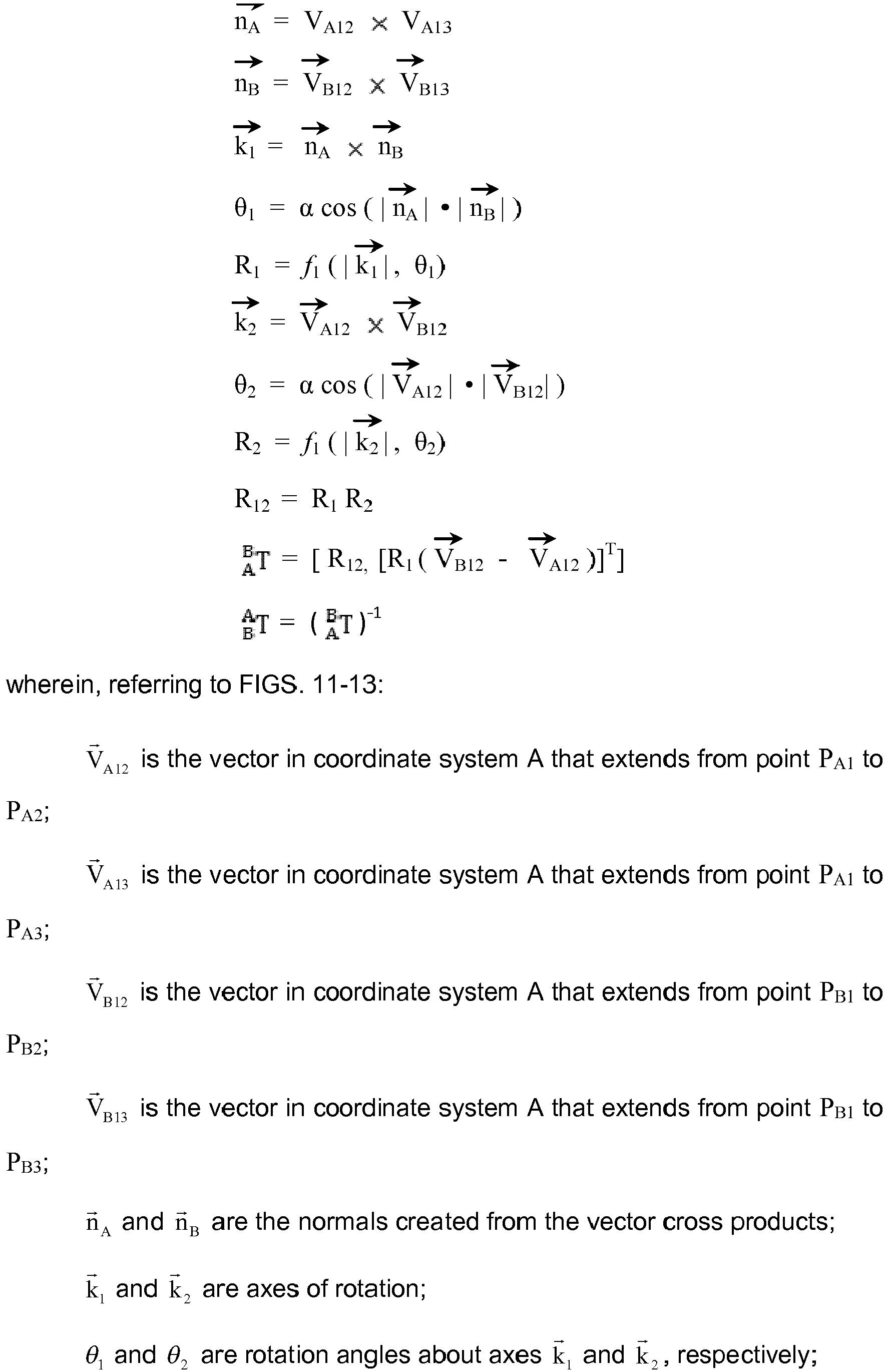


Claims (12)
- A location tracking system comprising:a pan-tilt mechanism (42);a camera (40) and a laser range finder mounted to said pan-tilt mechanism (42);a target object (10, 52, 90) equipped with at least three active target markers (P1-P3, 56a-c; 92a-c); anda computer (48) system programmed with first software for controlling the camera (40), the laser range finder and the pan-tilt mechanism (42), second software for processing images acquired by the camera (40), and third software for controlling motion of the target object (10, 52, 90) and states of the at least three active target markers (P1-P3, 56a-c; 92a-c).
- The system as recited in claim 1, wherein:the first software comprises routines for commanding the pan-tilt mechanism (42) to aim the camera (40) at the target object (10, 52, 90) and commanding the camera (40) to capture images of the target object (10, 52, 90);the second software comprises routines for processing captured images to compute a difference image representing differences between an image captured while the active target markers (P1-P3, 56a-c; 92a-c) were not on and each image captured while one or more of the active target markers (P1-P3, 56a-c; 92a-c) were on; andthe third software comprises routines for controlling the states of said active target markers (P1-P3, 56a-c; 92a-c).
- The system as recited in claim 1 or claim 2, wherein the target object (10, 52, 90) comprises a crawler vehicle (10).
- The system as recited in claim 3, wherein the crawler vehicle (10) is a holonomic motion crawler vehicle (52).
- The system as recited in claim 3 or claim 4, further comprising means for tracking incremental motion of said crawler vehicle (10, 52).
- The system as recited in claim 1 or claim 2, wherein the target object (10, 52, 90) comprises a base (84) of a robotic arm (86).
- A method of location tracking comprising the step of:
executing first, second and third software on a computer system, the computer system being programmed with the first, second and third software, and wherein:the first software comprises routines executable to cause the computer system to control a camera (40), a pan-tilt mechanism (42) and a laser range finder mounted to the pan-tilt mechanism (42);the second software comprises routines executable to process images acquired by the camera (40); andthe third software comprises routines executable to control motion of a target object (10, 52, 90) and states of at least three active target markers (P1-P3, 56a-c; 92a-c). - The method as recited in claim 7, wherein:the first software additionally comprises routines executable to cause the computer system to command the pan-tilt mechanism (42) to aim the camera (40) at the target object (10, 52, 90) and command the camera (40) to capture images of the target object (10, 52, 90);the second software additionally comprises routines executable to process captured images to compute a difference image representing differences between an image captured while the active target markers (P1-P3, 56a-c; 92a-c) were not on and each image captured while one or more of the active target markers (P1-P3, 56a-c; 92a-c) were on; andthe third software additionally comprises routines executable to control the states of said active target markers (P1-P3, 56a-c; 92a-c).
- The method as recited in claim 7 or claim 8, wherein the target object (10, 52, 90) comprises a crawler vehicle (10).
- The method as recited in claim 9, wherein the crawler vehicle (10) is a holonomic motion crawler vehicle (52).
- The method as recited in claim 9 or claim 10, further comprising means for tracking incremental motion of said crawler vehicle (10, 52).
- The method as recited in claim 7 or claim 8, wherein the target object (10, 52, 90) comprises a base (84) of a robotic arm (86).
Applications Claiming Priority (3)
| Application Number | Priority Date | Filing Date | Title |
|---|---|---|---|
| US13/921,246 US9043146B2 (en) | 2013-06-19 | 2013-06-19 | Systems and methods for tracking location of movable target object |
| EP14721694.9A EP3011362B1 (en) | 2013-06-19 | 2014-04-01 | Systems and methods for tracking location of movable target object |
| PCT/US2014/032503 WO2014204548A1 (en) | 2013-06-19 | 2014-04-01 | Systems and methods for tracking location of movable target object |
Related Parent Applications (2)
| Application Number | Title | Priority Date | Filing Date |
|---|---|---|---|
| EP14721694.9A Division EP3011362B1 (en) | 2013-06-19 | 2014-04-01 | Systems and methods for tracking location of movable target object |
| EP14721694.9A Division-Into EP3011362B1 (en) | 2013-06-19 | 2014-04-01 | Systems and methods for tracking location of movable target object |
Publications (1)
| Publication Number | Publication Date |
|---|---|
| EP3407088A1 true EP3407088A1 (en) | 2018-11-28 |
Family
ID=50640019
Family Applications (2)
| Application Number | Title | Priority Date | Filing Date |
|---|---|---|---|
| EP14721694.9A Not-in-force EP3011362B1 (en) | 2013-06-19 | 2014-04-01 | Systems and methods for tracking location of movable target object |
| EP18179415.7A Withdrawn EP3407088A1 (en) | 2013-06-19 | 2014-04-01 | Systems and methods for tracking location of movable target object |
Family Applications Before (1)
| Application Number | Title | Priority Date | Filing Date |
|---|---|---|---|
| EP14721694.9A Not-in-force EP3011362B1 (en) | 2013-06-19 | 2014-04-01 | Systems and methods for tracking location of movable target object |
Country Status (8)
| Country | Link |
|---|---|
| US (2) | US9043146B2 (en) |
| EP (2) | EP3011362B1 (en) |
| JP (1) | JP6426725B2 (en) |
| KR (1) | KR101988083B1 (en) |
| CN (1) | CN105518486B (en) |
| BR (1) | BR112015031505B1 (en) |
| RU (1) | RU2664257C2 (en) |
| WO (1) | WO2014204548A1 (en) |
Families Citing this family (85)
| Publication number | Priority date | Publication date | Assignee | Title |
|---|---|---|---|---|
| US9279679B2 (en) * | 2012-09-12 | 2016-03-08 | Kabushiki Kaisha Topcon | Construction machine control method and construction machine control system |
| US9404898B1 (en) * | 2013-03-15 | 2016-08-02 | The Boeing Company | Laser ultrasound testing in limited-access areas |
| US9410659B2 (en) | 2014-02-10 | 2016-08-09 | The Boeing Company | Automated mobile boom system for crawling robots |
| US10310054B2 (en) | 2014-03-21 | 2019-06-04 | The Boeing Company | Relative object localization process for local positioning system |
| US11126193B2 (en) * | 2014-06-19 | 2021-09-21 | Husqvarna Ab | Automatic beacon position determination |
| US9664652B2 (en) | 2014-10-30 | 2017-05-30 | The Boeing Company | Non-destructive ultrasonic inspection apparatus, systems, and methods |
| US9746447B2 (en) | 2014-10-30 | 2017-08-29 | The Boeing Company | Apparatuses, systems, and methods for inspecting a component |
| US9740191B2 (en) | 2015-02-12 | 2017-08-22 | The Boeing Company | Location calibration for automated production manufacturing |
| EP3064435A1 (en) * | 2015-03-03 | 2016-09-07 | Airbus Defence and Space, S.A. | Systems and methods for the calculation of relative distances and speeds in the three coordinate axis between aircraft in flight |
| US9924103B2 (en) | 2015-04-09 | 2018-03-20 | The Boeing Company | Automated local positioning system calibration using optically readable markers |
| CN105069795B (en) * | 2015-08-12 | 2017-12-22 | 深圳锐取信息技术股份有限公司 | Moving object tracking method and device |
| US10232897B2 (en) | 2015-10-16 | 2019-03-19 | The Boeing Company | Walking robot |
| CN105548989B (en) * | 2016-01-05 | 2018-01-02 | 西安应用光学研究所 | The anti-photoelectric observing of hand-held takes aim at and target positioning integrated apparatus |
| US10145670B2 (en) | 2016-01-12 | 2018-12-04 | The Boeing Company | Systems and methods for projected grid-based location tracking |
| US9892558B2 (en) | 2016-02-19 | 2018-02-13 | The Boeing Company | Methods for localization using geotagged photographs and three-dimensional visualization |
| KR20170109330A (en) * | 2016-03-21 | 2017-09-29 | 한화테크윈 주식회사 | Ladar system |
| US10325339B2 (en) * | 2016-04-26 | 2019-06-18 | Qualcomm Incorporated | Method and device for capturing image of traffic sign |
| CN106033615B (en) * | 2016-05-16 | 2017-09-15 | 北京旷视科技有限公司 | Destination object motion direction detecting method and device |
| US11137776B2 (en) * | 2016-05-16 | 2021-10-05 | SZ DJI Technology Co., Ltd. | Systems and methods for coordinating device actions |
| EP3485112B1 (en) | 2016-07-15 | 2021-08-25 | Fastbrick IP Pty Ltd | Vehicle which incorporates a brick laying machine |
| US10607409B2 (en) | 2016-07-19 | 2020-03-31 | The Boeing Company | Synthetic geotagging for computer-generated images |
| US10108872B2 (en) | 2016-07-29 | 2018-10-23 | Conduent Business Services, Llc | Multi-angle product imaging device |
| US10242581B2 (en) * | 2016-10-11 | 2019-03-26 | Insitu, Inc. | Method and apparatus for target relative guidance |
| US10347109B2 (en) | 2016-11-08 | 2019-07-09 | The Boeing Company | Automated human personnel fall arresting system and method |
| US10451714B2 (en) | 2016-12-06 | 2019-10-22 | Sony Corporation | Optical micromesh for computerized devices |
| US10536684B2 (en) | 2016-12-07 | 2020-01-14 | Sony Corporation | Color noise reduction in 3D depth map |
| US10181089B2 (en) * | 2016-12-19 | 2019-01-15 | Sony Corporation | Using pattern recognition to reduce noise in a 3D map |
| US10178370B2 (en) | 2016-12-19 | 2019-01-08 | Sony Corporation | Using multiple cameras to stitch a consolidated 3D depth map |
| RU2641604C1 (en) * | 2016-12-28 | 2018-01-18 | Федеральное государственное автономное образовательное учреждение высшего образования "Дальневосточный федеральный университет" (ДВФУ) | Method of measuring absolute position of end link of ndustrial robot multilink mechanism |
| JP6527178B2 (en) * | 2017-01-12 | 2019-06-05 | ファナック株式会社 | Vision sensor calibration device, method and program |
| US10495735B2 (en) | 2017-02-14 | 2019-12-03 | Sony Corporation | Using micro mirrors to improve the field of view of a 3D depth map |
| US10795022B2 (en) | 2017-03-02 | 2020-10-06 | Sony Corporation | 3D depth map |
| JP6774603B2 (en) * | 2017-03-06 | 2020-10-28 | 株式会社Jvcケンウッド | Laser light irradiation detection device, laser light irradiation detection method, laser light irradiation detection system |
| JP6854164B2 (en) * | 2017-03-22 | 2021-04-07 | 株式会社トプコン | Survey data processing device, survey data processing method, survey data processing system and survey data processing program |
| US10979687B2 (en) | 2017-04-03 | 2021-04-13 | Sony Corporation | Using super imposition to render a 3D depth map |
| CN109029391B (en) * | 2017-05-18 | 2020-09-15 | 金钱猫科技股份有限公司 | Coordinate transformation-based real object measurement method, system and device |
| US11085611B2 (en) * | 2017-06-15 | 2021-08-10 | Board Of Supervisors Of Louisiana State University And Agricultural And Mechanical College | Tracking lighting system |
| US10796477B2 (en) * | 2017-06-20 | 2020-10-06 | Edx Technologies, Inc. | Methods, devices, and systems for determining field of view and producing augmented reality |
| WO2019006511A1 (en) | 2017-07-05 | 2019-01-10 | Fastbrick Ip Pty Ltd | Real time position and orientation tracker |
| CN111052188B (en) | 2017-07-27 | 2023-11-24 | 西屋电气有限责任公司 | Method for positioning a remotely operated vehicle in a workspace and remote inspection system employing such a method |
| CN111213098B (en) * | 2017-08-17 | 2024-03-15 | 快砖知识产权私人有限公司 | Communication system for interactive system |
| EP3669138B1 (en) | 2017-08-17 | 2023-05-24 | Fastbrick IP Pty Ltd | Laser tracker with improved roll angle measurement |
| US10791275B2 (en) * | 2017-09-25 | 2020-09-29 | The Boeing Company | Methods for measuring and inspecting structures using cable-suspended platforms |
| US10788428B2 (en) * | 2017-09-25 | 2020-09-29 | The Boeing Company | Positioning system for aerial non-destructive inspection |
| CN109557329B (en) * | 2017-09-26 | 2022-07-19 | 深圳市新产业生物医学工程股份有限公司 | Rotary sample adding device and sample adding method |
| EP3673334B1 (en) * | 2017-09-30 | 2023-05-24 | Siemens Aktiengesellschaft | Method for engineering autonomous system with reusable skills |
| JP6603289B2 (en) * | 2017-10-27 | 2019-11-06 | ファナック株式会社 | Robot, robot system, and robot coordinate system setting method |
| US10484667B2 (en) | 2017-10-31 | 2019-11-19 | Sony Corporation | Generating 3D depth map using parallax |
| US10818097B2 (en) | 2017-12-12 | 2020-10-27 | Disney Enterprises, Inc. | Spatial position calculation system for objects in virtual reality or augmented reality environment |
| CN110579738B (en) * | 2018-06-11 | 2021-06-25 | 深圳市优必选科技有限公司 | Moving target direction angle obtaining method and terminal equipment |
| EP3581341B1 (en) * | 2018-06-13 | 2020-12-23 | Siemens Healthcare GmbH | Method for operating a robot, data storage having a program code, robot and robot system |
| US10800550B2 (en) | 2018-06-21 | 2020-10-13 | The Boeing Company | Positioning enhancements to localization process for three-dimensional visualization |
| US10549186B2 (en) | 2018-06-26 | 2020-02-04 | Sony Interactive Entertainment Inc. | Multipoint SLAM capture |
| US11007635B2 (en) * | 2018-07-25 | 2021-05-18 | The Boeing Company | Gravity compensation for self-propelled robotic vehicles crawling on non-level surfaces |
| US10949980B2 (en) * | 2018-10-30 | 2021-03-16 | Alt Llc | System and method for reverse optical tracking of a moving object |
| CN111121619A (en) * | 2018-11-01 | 2020-05-08 | 西南科技大学 | Space geometry automatic measurement method based on laser ranging |
| JP7000361B2 (en) * | 2019-01-24 | 2022-01-19 | ファナック株式会社 | Follow-up robot and work robot system |
| CN109945782B (en) * | 2019-04-02 | 2020-12-08 | 易思维(杭州)科技有限公司 | Method for detecting key position of super-long body-in-white |
| CN110068827A (en) * | 2019-04-29 | 2019-07-30 | 西北工业大学 | A kind of method of the autonomous object ranging of unmanned plane |
| RU2714701C1 (en) * | 2019-06-17 | 2020-02-19 | Федеральное государственное унитарное предприятие "Российский федеральный ядерный центр - Всероссийский научно-исследовательский институт технической физики имени академика Е.И. Забабахина" | Method of selecting an object on a distant background with optical systems from an air carrier |
| US11361869B2 (en) * | 2019-08-13 | 2022-06-14 | Westinghouse Electric Company Llc | System and method enabling signals from replacement self-powered neutron detectors to be used to generate inputs to legacy software |
| CN110780325B (en) * | 2019-08-23 | 2022-07-19 | 腾讯科技(深圳)有限公司 | Method and device for positioning moving object and electronic equipment |
| JP7435998B2 (en) * | 2019-09-17 | 2024-02-21 | 日本電気通信システム株式会社 | Article position management device, article, article position management system, article position management method and program |
| FI20196022A1 (en) * | 2019-11-27 | 2021-05-28 | Novatron Oy | Method and positioning system for determining location and orientation of machine |
| JP7406902B2 (en) * | 2019-12-10 | 2023-12-28 | キヤノン株式会社 | Control device, control method, program, method and storage medium |
| US10846880B1 (en) * | 2020-01-03 | 2020-11-24 | Altec Industries, Inc. | Camera embedded joystick |
| US11631251B2 (en) * | 2020-02-23 | 2023-04-18 | Tfi Digital Media Limited | Method and system for jockey and horse recognition and tracking |
| WO2021217371A1 (en) * | 2020-04-27 | 2021-11-04 | 深圳市大疆创新科技有限公司 | Control method and apparatus for movable platform |
| CN111474519A (en) * | 2020-04-28 | 2020-07-31 | 广东博智林机器人有限公司 | Positioning method, device, equipment and storage medium |
| CN111753663B (en) * | 2020-05-25 | 2023-12-12 | 上海欧菲智能车联科技有限公司 | Target detection method and device |
| CN111931614B (en) * | 2020-07-24 | 2024-04-19 | 深圳市瑞立视多媒体科技有限公司 | Active light rigid body identification method, device, equipment and storage medium |
| CN112116651B (en) * | 2020-08-12 | 2023-04-07 | 天津(滨海)人工智能军民融合创新中心 | Ground target positioning method and system based on monocular vision of unmanned aerial vehicle |
| RU2756437C1 (en) * | 2020-09-03 | 2021-09-30 | Публичное Акционерное Общество "Сбербанк России" (Пао Сбербанк) | Method and system for planning the movement of a manipulator robot by correcting the reference trajectories |
| CN112595231A (en) * | 2020-12-10 | 2021-04-02 | 上海镭隆科技发展有限公司 | Two-dimensional follow-up system dynamic monitoring device and method based on intelligent image recognition |
| CN112822353B (en) * | 2020-12-28 | 2022-03-01 | 维沃移动通信有限公司 | Electronic equipment and camera module thereof |
| CN112991401B (en) * | 2021-01-20 | 2023-07-14 | 深兰科技(上海)有限公司 | Vehicle running track tracking method and device, electronic equipment and storage medium |
| CN113050108B (en) * | 2021-03-23 | 2024-01-09 | 湖南盛鼎科技发展有限责任公司 | Electronic world site vision measurement system and measurement method |
| CN113358332B (en) * | 2021-07-15 | 2022-03-22 | 中国科学院长春光学精密机械与物理研究所 | Dynamic imaging telescope performance detection device and method |
| US11502729B1 (en) | 2021-08-10 | 2022-11-15 | The Boeing Company | Methods for through-structure power and data transfer between mobile robots and sensor nodes |
| CN114235457B (en) * | 2021-12-20 | 2024-03-15 | 浙江谱麦科技有限公司 | Force loading system for detecting robot mechanical performance and system adjustment method |
| US20230241719A1 (en) * | 2022-01-31 | 2023-08-03 | Standex International Corporation | Techniques for closed-loop control of a laser-engraving process |
| CN115435764B (en) * | 2022-11-09 | 2022-12-30 | 中国空气动力研究与发展中心设备设计与测试技术研究所 | A sucking disc formula walking robot for scanning of laser tracker target spot |
| CN115861429B (en) * | 2023-02-28 | 2023-06-16 | 深圳思谋信息科技有限公司 | Image acquisition equipment calibration method, device, computer equipment and storage medium |
| CN116931583B (en) * | 2023-09-19 | 2023-12-19 | 深圳市普渡科技有限公司 | Method, device, equipment and storage medium for determining and avoiding moving object |
| CN117516811A (en) * | 2023-10-09 | 2024-02-06 | 南京智谱科技有限公司 | Gas leakage monitoring system, method and device and inspection device |
Citations (1)
| Publication number | Priority date | Publication date | Assignee | Title |
|---|---|---|---|---|
| US20090086199A1 (en) * | 2007-09-28 | 2009-04-02 | The Boeing Company | Method involving a pointing instrument and a target object |
Family Cites Families (26)
| Publication number | Priority date | Publication date | Assignee | Title |
|---|---|---|---|---|
| US4424943A (en) * | 1981-05-04 | 1984-01-10 | Hughes Aircraft Company | Tracking system |
| US4786167A (en) * | 1985-10-03 | 1988-11-22 | Rothbone Richard R | Optical navigation system |
| US5673082A (en) * | 1995-04-10 | 1997-09-30 | The United States Of America As Represented By The Administrator Of The National Aeronautics And Space Administration | Light-directed ranging system implementing single camera system for telerobotics applications |
| US5974348A (en) * | 1996-12-13 | 1999-10-26 | Rocks; James K. | System and method for performing mobile robotic work operations |
| JP3909377B2 (en) * | 1997-02-14 | 2007-04-25 | 株式会社安川電機 | Outdoor distance measuring device |
| FR2770672B1 (en) * | 1997-11-04 | 2000-01-21 | Inst Nat Rech Inf Automat | METHOD AND DEVICE FOR LOCATING AND GUIDING A MOBILE PROVIDED WITH A LINEAR CAMERA |
| US6198485B1 (en) * | 1998-07-29 | 2001-03-06 | Intel Corporation | Method and apparatus for three-dimensional input entry |
| AT412033B (en) * | 2000-02-08 | 2004-08-26 | Efkon Entwicklung Forschung & Konstruktion Von Sondermaschinen Gmbh | SYSTEM FOR AUTOMATIC CHARGING OF FEES |
| AU2001284519A1 (en) * | 2000-09-11 | 2002-03-26 | Kunikatsu Takase | Mobile body position detecting system |
| US7162338B2 (en) * | 2002-12-17 | 2007-01-09 | Evolution Robotics, Inc. | Systems and methods for computing a relative pose for global localization in a visual simultaneous localization and mapping system |
| US7419140B2 (en) | 2005-05-16 | 2008-09-02 | Safeguards Technology Llc | Security fence module |
| GB0513899D0 (en) | 2005-07-06 | 2005-08-10 | Airbus Uk Ltd | Program-controlled process |
| JP4799088B2 (en) * | 2005-09-06 | 2011-10-19 | 株式会社東芝 | Method and apparatus for measuring work position in remote inspection |
| US7599789B2 (en) * | 2006-05-24 | 2009-10-06 | Raytheon Company | Beacon-augmented pose estimation |
| US7643893B2 (en) | 2006-07-24 | 2010-01-05 | The Boeing Company | Closed-loop feedback control using motion capture systems |
| ITFI20060196A1 (en) * | 2006-08-04 | 2008-02-05 | Fasep 2000 S R L | METHOD AND DEVICE FOR MEASURING WITHOUT CONTACT WITH WHEEL ALIGNMENT OF MOTOR VEHICLES |
| US9176598B2 (en) * | 2007-05-08 | 2015-11-03 | Thinkoptics, Inc. | Free-space multi-dimensional absolute pointer with improved performance |
| US8044991B2 (en) * | 2007-09-28 | 2011-10-25 | The Boeing Company | Local positioning system and method |
| US9189858B2 (en) * | 2008-02-29 | 2015-11-17 | Trimble Ab | Determining coordinates of a target in relation to a survey instrument having at least two cameras |
| JP5157803B2 (en) * | 2008-10-06 | 2013-03-06 | 村田機械株式会社 | Autonomous mobile device |
| US8199194B2 (en) | 2008-10-07 | 2012-06-12 | The Boeing Company | Method and system involving controlling a video camera to track a movable target object |
| US8279412B2 (en) * | 2009-12-17 | 2012-10-02 | The Boeing Company | Position and orientation determination using movement data |
| US8447805B2 (en) * | 2011-02-28 | 2013-05-21 | The Boeing Company | Distributed operation of a local positioning system |
| US8738226B2 (en) * | 2011-07-18 | 2014-05-27 | The Boeing Company | Holonomic motion vehicle for travel on non-level surfaces |
| US8874371B2 (en) * | 2011-08-09 | 2014-10-28 | The Boeing Company | Beam directed motion control system |
| WO2013045517A1 (en) * | 2011-09-27 | 2013-04-04 | Leica Geosystems Ag | Measuring system and method for marking a known target point in a coordinate system |
-
2013
- 2013-06-19 US US13/921,246 patent/US9043146B2/en active Active
-
2014
- 2014-04-01 BR BR112015031505-4A patent/BR112015031505B1/en not_active IP Right Cessation
- 2014-04-01 RU RU2015141333A patent/RU2664257C2/en active
- 2014-04-01 EP EP14721694.9A patent/EP3011362B1/en not_active Not-in-force
- 2014-04-01 WO PCT/US2014/032503 patent/WO2014204548A1/en active Application Filing
- 2014-04-01 EP EP18179415.7A patent/EP3407088A1/en not_active Withdrawn
- 2014-04-01 JP JP2016521401A patent/JP6426725B2/en active Active
- 2014-04-01 CN CN201480034791.8A patent/CN105518486B/en not_active Expired - Fee Related
- 2014-06-23 KR KR1020157031027A patent/KR101988083B1/en active IP Right Grant
-
2015
- 2015-03-30 US US14/672,952 patent/US9197810B2/en not_active Expired - Fee Related
Patent Citations (2)
| Publication number | Priority date | Publication date | Assignee | Title |
|---|---|---|---|---|
| US20090086199A1 (en) * | 2007-09-28 | 2009-04-02 | The Boeing Company | Method involving a pointing instrument and a target object |
| US7859655B2 (en) | 2007-09-28 | 2010-12-28 | The Boeing Company | Method involving a pointing instrument and a target object |
Also Published As
| Publication number | Publication date |
|---|---|
| KR101988083B1 (en) | 2019-09-30 |
| US9043146B2 (en) | 2015-05-26 |
| RU2015141333A (en) | 2017-07-24 |
| US20150207987A1 (en) | 2015-07-23 |
| US20140376768A1 (en) | 2014-12-25 |
| RU2664257C2 (en) | 2018-08-15 |
| EP3011362B1 (en) | 2018-10-17 |
| WO2014204548A1 (en) | 2014-12-24 |
| BR112015031505A2 (en) | 2017-07-25 |
| JP6426725B2 (en) | 2018-11-28 |
| US9197810B2 (en) | 2015-11-24 |
| CN105518486B (en) | 2017-09-19 |
| RU2015141333A3 (en) | 2018-03-20 |
| KR20160044432A (en) | 2016-04-25 |
| CN105518486A (en) | 2016-04-20 |
| BR112015031505B1 (en) | 2022-02-22 |
| EP3011362A1 (en) | 2016-04-27 |
| JP2016526673A (en) | 2016-09-05 |
Similar Documents
| Publication | Publication Date | Title |
|---|---|---|
| EP3011362B1 (en) | Systems and methods for tracking location of movable target object | |
| CN108571971B (en) | AGV visual positioning system and method | |
| CN102448679B (en) | Method and system for extremely precise positioning of at least one object in the end position in space | |
| US20200078948A1 (en) | Robot calibration for ar and digital twin | |
| US20200238525A1 (en) | System and method for automatic hand-eye calibration of vision system for robot motion | |
| US9457470B2 (en) | Robot system and method for calibration | |
| JP4021413B2 (en) | Measuring device | |
| CN103020952B (en) | Messaging device and information processing method | |
| CN104786226A (en) | Posture and moving track positioning system and method of robot grabbing online workpiece | |
| JP6855492B2 (en) | Robot system, robot system control device, and robot system control method | |
| Palmieri et al. | A comparison between position-based and image-based dynamic visual servoings in the control of a translating parallel manipulator | |
| CN204585232U (en) | Capture robot pose and the movement locus navigation system of online workpiece | |
| JP2019076972A (en) | Automation apparatus | |
| CN106737859A (en) | The method for calibrating external parameters of sensor and robot based on invariable plane | |
| CN111780715A (en) | Visual ranging method | |
| Grudziński et al. | Stereovision tracking system for monitoring loader crane tip position | |
| CN109773589A (en) | Method and device, the equipment of on-line measurement and processing guiding are carried out to workpiece surface | |
| US20230123629A1 (en) | 3d computer-vision system with variable spatial resolution | |
| Gans et al. | Visual servoing to an arbitrary pose with respect to an object given a single known length | |
| McArthur et al. | Pose-estimate-based target tracking for human-guided remote sensor mounting with a UAV | |
| CN113845064B (en) | Positioning method and system for material bearing device with round support legs | |
| Pajor et al. | Stereovision system for motion tracking and position error compensation of loading crane | |
| Ahmadinejad et al. | A low-cost vision-based tracking system for position control of quadrotor robots | |
| JP7278637B2 (en) | Self-propelled moving device | |
| Skov et al. | 3D Navigation by UAV using a mono-camera, for precise target tracking for contact inspection of critical infrastructures |
Legal Events
| Date | Code | Title | Description |
|---|---|---|---|
| PUAI | Public reference made under article 153(3) epc to a published international application that has entered the european phase |
Free format text: ORIGINAL CODE: 0009012 |
|
| STAA | Information on the status of an ep patent application or granted ep patent |
Free format text: STATUS: REQUEST FOR EXAMINATION WAS MADE |
|
| 17P | Request for examination filed |
Effective date: 20180622 |
|
| AC | Divisional application: reference to earlier application |
Ref document number: 3011362 Country of ref document: EP Kind code of ref document: P |
|
| AK | Designated contracting states |
Kind code of ref document: A1 Designated state(s): AL AT BE BG CH CY CZ DE DK EE ES FI FR GB GR HR HU IE IS IT LI LT LU LV MC MK MT NL NO PL PT RO RS SE SI SK SM TR |
|
| STAA | Information on the status of an ep patent application or granted ep patent |
Free format text: STATUS: EXAMINATION IS IN PROGRESS |
|
| STAA | Information on the status of an ep patent application or granted ep patent |
Free format text: STATUS: EXAMINATION IS IN PROGRESS |
|
| 17Q | First examination report despatched |
Effective date: 20201117 |
|
| STAA | Information on the status of an ep patent application or granted ep patent |
Free format text: STATUS: EXAMINATION IS IN PROGRESS |
|
| RAP3 | Party data changed (applicant data changed or rights of an application transferred) |
Owner name: THE BOEING COMPANY |
|
| STAA | Information on the status of an ep patent application or granted ep patent |
Free format text: STATUS: THE APPLICATION IS DEEMED TO BE WITHDRAWN |
|
| 18D | Application deemed to be withdrawn |
Effective date: 20230628 |