EP3407056A1 - Method for detecting corrosion of a surface not exposed to view of a metal piece, by means of thermographic analysis - Google Patents
Method for detecting corrosion of a surface not exposed to view of a metal piece, by means of thermographic analysis Download PDFInfo
- Publication number
- EP3407056A1 EP3407056A1 EP17172671.4A EP17172671A EP3407056A1 EP 3407056 A1 EP3407056 A1 EP 3407056A1 EP 17172671 A EP17172671 A EP 17172671A EP 3407056 A1 EP3407056 A1 EP 3407056A1
- Authority
- EP
- European Patent Office
- Prior art keywords
- metal piece
- wall
- laser beam
- portions
- exposed
- Prior art date
- Legal status (The legal status is an assumption and is not a legal conclusion. Google has not performed a legal analysis and makes no representation as to the accuracy of the status listed.)
- Granted
Links
Images

Classifications
-
- G—PHYSICS
- G01—MEASURING; TESTING
- G01N—INVESTIGATING OR ANALYSING MATERIALS BY DETERMINING THEIR CHEMICAL OR PHYSICAL PROPERTIES
- G01N25/00—Investigating or analyzing materials by the use of thermal means
- G01N25/72—Investigating presence of flaws
-
- G—PHYSICS
- G01—MEASURING; TESTING
- G01N—INVESTIGATING OR ANALYSING MATERIALS BY DETERMINING THEIR CHEMICAL OR PHYSICAL PROPERTIES
- G01N21/00—Investigating or analysing materials by the use of optical means, i.e. using sub-millimetre waves, infrared, visible or ultraviolet light
- G01N21/62—Systems in which the material investigated is excited whereby it emits light or causes a change in wavelength of the incident light
- G01N21/71—Systems in which the material investigated is excited whereby it emits light or causes a change in wavelength of the incident light thermally excited
-
- G—PHYSICS
- G01—MEASURING; TESTING
- G01J—MEASUREMENT OF INTENSITY, VELOCITY, SPECTRAL CONTENT, POLARISATION, PHASE OR PULSE CHARACTERISTICS OF INFRARED, VISIBLE OR ULTRAVIOLET LIGHT; COLORIMETRY; RADIATION PYROMETRY
- G01J5/00—Radiation pyrometry, e.g. infrared or optical thermometry
- G01J5/10—Radiation pyrometry, e.g. infrared or optical thermometry using electric radiation detectors
-
- G—PHYSICS
- G01—MEASURING; TESTING
- G01N—INVESTIGATING OR ANALYSING MATERIALS BY DETERMINING THEIR CHEMICAL OR PHYSICAL PROPERTIES
- G01N21/00—Investigating or analysing materials by the use of optical means, i.e. using sub-millimetre waves, infrared, visible or ultraviolet light
- G01N21/84—Systems specially adapted for particular applications
- G01N21/88—Investigating the presence of flaws or contamination
-
- G—PHYSICS
- G01—MEASURING; TESTING
- G01J—MEASUREMENT OF INTENSITY, VELOCITY, SPECTRAL CONTENT, POLARISATION, PHASE OR PULSE CHARACTERISTICS OF INFRARED, VISIBLE OR ULTRAVIOLET LIGHT; COLORIMETRY; RADIATION PYROMETRY
- G01J5/00—Radiation pyrometry, e.g. infrared or optical thermometry
- G01J2005/0077—Imaging
-
- G—PHYSICS
- G01—MEASURING; TESTING
- G01J—MEASUREMENT OF INTENSITY, VELOCITY, SPECTRAL CONTENT, POLARISATION, PHASE OR PULSE CHARACTERISTICS OF INFRARED, VISIBLE OR ULTRAVIOLET LIGHT; COLORIMETRY; RADIATION PYROMETRY
- G01J5/00—Radiation pyrometry, e.g. infrared or optical thermometry
- G01J5/48—Thermography; Techniques using wholly visual means
- G01J5/485—Temperature profile
Definitions
- the present invention relates to a method for detecting corrosion of a surface not exposed to view of a metal piece, wherein radiant thermal energy is directed against the metal piece by illuminating the piece with a pulsed laser beam, so as to cause heating of the metal piece, and wherein the infrared radiation emitted by the metal piece is detected by a thermographic camera, in such a way that corroded portions of said surface are located due to a different thermal response as a function of time of the corroded portions of said surface with respect to non-corroded portions.
- a method of the above indicated type is for example disclosed in DE 10 2010 023 655 A1 .
- the method known from this document is applied to the detection of corroded portions of the surface of a metal sheet which is not exposed to view, since it is covered by a varnish layer.
- the laser beam is directed against the sheet metal element from the side of the above mentioned surface coated with a varnish layer, any corrosion of this surface being to be detected.
- the thermographic camera for the thermographic analysis is arranged on the opposite side of the sheet metal element, so that it receives the infrared radiation emitted by the sheet metal element on the side opposite to that from which the laser beam comes.
- thermographic detection of corroded surfaces which enable any corrosion of a sheet element to be detected on the face of the element which is opposite to the face which is exposed to view.
- the present invention has the object of providing a new method for detection of any corroded portions of surfaces of metal elements.
- the invention aims in particular to providing a method of the above indicated type which can be advantageously used in the automotive industry, for detecting corroded portions of surfaces of components of motor-vehicle structures, or sub-assemblies of motor-vehicle structures, or entire motor-vehicle bodies, on a side which is not exposed to view.
- the invention provides a method having the features indicated at the beginning of the present description and further characterized in that:
- the method according to the invention can be advantageously used for locating any corroded portions of the inner surface of hollow components constituted by welded sheet metal elements.
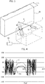
- Figure 1 shows, by way of example, an application of the method according to the invention in which an instrument 1 for thermographic analysis is carried by a robotized arm 2 of any known type. It is clearly apparent that this embodiment has no limiting value, since the method according to the invention can be carried out by making use of any type of supporting structure for supporting the instrument 1. Also the case in which the instrument is directly carried and operated by an operator is possible.
- the robotized arm 2 is driven by a respective electronic controller E, which also includes a processing electronic control unit associated with the detection instrument 1.
- An operator W can control the movements of the robotized arm 2 and the orientation of the detection instrument 1, for example by means of a programming device or tablet T.
- the detection instrument 1 is used for detecting any corroded portions of the inner surface of a hollow component 3 of metal material, arranged above a bench 4 inside a work cell C.
- the detection instrument 1 can be mounted on a pedestal which can be manually moved by the operator, or could be carried directly by the operator. It is further evident that the method according to the invention can be carried out both in a work cell C as that shown by way of example in figure 1 , as well as in a production line, or in a workshop in which a motor-vehicle must undergo maintenance or repairing operations.
- the detection instrument 1 includes a laser head 5 and a thermographic camera 6 which are therefore arranged on a same side with respect to a wall 30 of the component 3 to be analyzed.
- the laser head 5 directs a laser beam F, specifically a pulsed laser beam, against a face 30a of the wall 30 which is exposed to view.
- a laser beam F specifically a pulsed laser beam
- the opposite face 30b of the wall 30, which is hidden from view, is that whose surface may have corroded portions X which can be detected by means of the method of the invention.
- thermographic camera 6 As a result of the laser radiation F, wall 30 is heated and emits infrared radiation IR which is detected by the thermographic camera 6.
- the thermographic camera 6 is connected to a processing electronic control system E1 ( figure 3 ) (which in the case of the example of figure 1 can also be integrated within controller E) adapted to detect the presence of the corroded portions X of surface 30b due to the different response as a function of time of the parts of wall 30 which have the corroded portions X and the parts of wall 30 which do not have corroded portions.
- this analysis is specifically conducted during the cooling stage of the metal piece, after that the illumination by the laser beam has been interrupted.
- Figure 4 shows an example of a diagram showing the different thermal response of the corroded portions (line C) and non-corroded portions (line NC) of wall 30.
- the diagram shows the phase of the thermographic signal for different pixels of the examined area of the wall, along a transverse direction with respect to the optical axis of the thermographic camera.
- thermographic camera provided with a processing electronic control system configured for carrying out a "Lock-in" thermography.
- Lock-in thermography is a method for thermographic analysis which is per se well known to the skilled experts.
- the basic idea behind Lock-in thermography is that a temperature modulation induced by a heating system having a sinusoidal shape, on the surface of a piece, propagates as a thermal wave. This thermal wave undergoes reflections as any wave, so that the temperature modulation on the surface is modified by the thermal wave which is reflected by the piece.
- For each pixel for example by analyzing four images with phase intervals of one quarter of a period, it is possible to calculate the phase offset between the emitted energy and the local thermal response and the maximum amplitude of the periodic thermal signal.
- the phase image is not affected by these disturbances and is therefore more reliable and sensitive. Furthermore, by conducting a phase analysis, the theoretical depth at which a defect can be detected is approximately the double of what is possible with an amplitude analysis.
- the detection system can detect variation of thickness of the wall caused by the presence of the corroded portions X on face 30b.
- the method according to the invention can be advantageously used in the automotive industry, both in a work area as that shown in figure 1 of the annexed drawings, or in a production line, or in a workshop in which a motor-vehicle must undergo maintenance or repairing operations.
- the operator can directly control the detecting instrument 1 by manually positioning the instrument adjacent to the component to be examined, or he may make use of any supporting structure or other equipment (such for instance also a robotized arm) for controlling the position of the detection instrument 1 with respect to the piece. It is not even excluded the possibility to hold the detection instrument at a fixed position and moving the piece with respect to the instrument, in order to examine different portions of the piece.
- the method according to the invention performs a detection of the corrosion of a face hidden to view of a wall of the metal piece to be examined, whose opposite face is illuminated by a pulsed laser beam.
- the detection instrument includes both the laser head 5 and the thermographic camera 6, which therefore are both arranged on a same side with respect to the analyzed wall.
Landscapes
- Health & Medical Sciences (AREA)
- General Physics & Mathematics (AREA)
- Physics & Mathematics (AREA)
- Chemical & Material Sciences (AREA)
- Life Sciences & Earth Sciences (AREA)
- Analytical Chemistry (AREA)
- Biochemistry (AREA)
- General Health & Medical Sciences (AREA)
- Immunology (AREA)
- Pathology (AREA)
- Nuclear Medicine, Radiotherapy & Molecular Imaging (AREA)
- Spectroscopy & Molecular Physics (AREA)
- Investigating Or Analyzing Materials Using Thermal Means (AREA)
Abstract
Description
- The present invention relates to a method for detecting corrosion of a surface not exposed to view of a metal piece, wherein radiant thermal energy is directed against the metal piece by illuminating the piece with a pulsed laser beam, so as to cause heating of the metal piece, and wherein the infrared radiation emitted by the metal piece is detected by a thermographic camera, in such a way that corroded portions of said surface are located due to a different thermal response as a function of time of the corroded portions of said surface with respect to non-corroded portions.
- A method of the above indicated type is for example disclosed in
DE 10 2010 023 655 A1 . The method known from this document is applied to the detection of corroded portions of the surface of a metal sheet which is not exposed to view, since it is covered by a varnish layer. Also in the case of this known solution, the laser beam is directed against the sheet metal element from the side of the above mentioned surface coated with a varnish layer, any corrosion of this surface being to be detected. Furthermore, the thermographic camera for the thermographic analysis is arranged on the opposite side of the sheet metal element, so that it receives the infrared radiation emitted by the sheet metal element on the side opposite to that from which the laser beam comes. - This known solution necessarily implies that sufficient space is available on both sides of the sheet metal element, in order to arrange the laser device on one side and the thermographic camera on the opposite side.
- Furthermore, the need exists of providing methods for thermographic detection of corroded surfaces which enable any corrosion of a sheet element to be detected on the face of the element which is opposite to the face which is exposed to view.
- The present invention has the object of providing a new method for detection of any corroded portions of surfaces of metal elements.
- The invention aims in particular to providing a method of the above indicated type which can be advantageously used in the automotive industry, for detecting corroded portions of surfaces of components of motor-vehicle structures, or sub-assemblies of motor-vehicle structures, or entire motor-vehicle bodies, on a side which is not exposed to view.
- In view of achieving the above indicated objects, the invention provides a method having the features indicated at the beginning of the present description and further characterized in that:
- the beam of laser light is directed against a face exposed to view of a wall of said metal piece, whose opposite face is the surface on which any corrosion must be detected,
- said thermographic camera is provided on the same side, with respect to said wall, as that where a laser head for emitting said laser beam is provided,
- said thermographic camera is provided with a processing electronic control system, configured for carrying out a "Lock-in" thermography,
- detection of corroded portions of said surface is carried out by comparing the response of different surface portions during cooling of the piece, after that illumination with the laser beam has been interrupted.
- Studies and tests conducted by the applicant have shown that due to the above mentioned features it is possible to detect with optimal approximation the presence of corroded portions on the face of a wall opposite to the face which is exposed to view and which is illuminated by said laser beam. For example, due to the above mentioned features, the method according to the invention can be advantageously used for locating any corroded portions of the inner surface of hollow components constituted by welded sheet metal elements.
- According to a further preferred feature of the present invention, the processing control electronic system with which the thermographic camera is provided is configured for carrying out an approximated evaluation of the wall local thickness L on the basis of the following relation:

so that an approximated detection of the variation of thickness of said wall due to the corroded surface can be obtained. - Further features and advantages of the invention will become apparent from the description which follows with reference to the annexed drawings, given purely by way of non limiting example, in which:
-
figure 1 is a diagrammatic view which shows an application of the method according to the invention, in which an instrument for thermographic analysis carried by a robotized arm is used for detecting corroded portions of the inner surface of a hollow metal component, -
figure 2 is a further diagram which shows the principle of operation which is at the basis of the method according to the invention, -
figure 3 is a further perspective diagram corresponding to that offigure 2 , and -
figure 4 is a diagram which shows the result which can be obtained by the system for thermographic analysis which is used in the present invention. -
Figure 1 shows, by way of example, an application of the method according to the invention in which aninstrument 1 for thermographic analysis is carried by a robotized arm 2 of any known type. It is clearly apparent that this embodiment has no limiting value, since the method according to the invention can be carried out by making use of any type of supporting structure for supporting theinstrument 1. Also the case in which the instrument is directly carried and operated by an operator is possible. - In the case of the illustrated example, the robotized arm 2 is driven by a respective electronic controller E, which also includes a processing electronic control unit associated with the
detection instrument 1. An operator W can control the movements of the robotized arm 2 and the orientation of thedetection instrument 1, for example by means of a programming device or tablet T. Also in the case of the illustrated example, thedetection instrument 1 is used for detecting any corroded portions of the inner surface of ahollow component 3 of metal material, arranged above abench 4 inside a work cell C. - As already indicated in the foregoing, this solution is purely given by way of example. The
detection instrument 1 can be mounted on a pedestal which can be manually moved by the operator, or could be carried directly by the operator. It is further evident that the method according to the invention can be carried out both in a work cell C as that shown by way of example infigure 1 , as well as in a production line, or in a workshop in which a motor-vehicle must undergo maintenance or repairing operations. - With reference to
figures 2 ,3 thedetection instrument 1 includes alaser head 5 and athermographic camera 6 which are therefore arranged on a same side with respect to awall 30 of thecomponent 3 to be analyzed. - As shown in
figures 2 ,3 , thelaser head 5 directs a laser beam F, specifically a pulsed laser beam, against aface 30a of thewall 30 which is exposed to view. Theopposite face 30b of thewall 30, which is hidden from view, is that whose surface may have corroded portions X which can be detected by means of the method of the invention. - As a result of the laser radiation F,
wall 30 is heated and emits infrared radiation IR which is detected by thethermographic camera 6. Thethermographic camera 6 is connected to a processing electronic control system E1 (figure 3 ) (which in the case of the example offigure 1 can also be integrated within controller E) adapted to detect the presence of the corroded portions X ofsurface 30b due to the different response as a function of time of the parts ofwall 30 which have the corroded portions X and the parts ofwall 30 which do not have corroded portions. - According to the invention, this analysis is specifically conducted during the cooling stage of the metal piece, after that the illumination by the laser beam has been interrupted.
-
Figure 4 shows an example of a diagram showing the different thermal response of the corroded portions (line C) and non-corroded portions (line NC) ofwall 30. The diagram shows the phase of the thermographic signal for different pixels of the examined area of the wall, along a transverse direction with respect to the optical axis of the thermographic camera. - Studies and tests conducted by the applicant have shown that a relatively precise detection can be obtained by making use of a thermographic camera provided with a processing electronic control system configured for carrying out a "Lock-in" thermography.
- "Lock-in" thermography is a method for thermographic analysis which is per se well known to the skilled experts. The basic idea behind Lock-in thermography is that a temperature modulation induced by a heating system having a sinusoidal shape, on the surface of a piece, propagates as a thermal wave. This thermal wave undergoes reflections as any wave, so that the temperature modulation on the surface is modified by the thermal wave which is reflected by the piece. For each pixel, for example by analyzing four images with phase intervals of one quarter of a period, it is possible to calculate the phase offset between the emitted energy and the local thermal response and the maximum amplitude of the periodic thermal signal. Whereas the amplitude image is affected by disomogeneities in absorption by the surface of the infrared emissions and the heating distribution, the phase image is not affected by these disturbances and is therefore more reliable and sensitive. Furthermore, by conducting a phase analysis, the theoretical depth at which a defect can be detected is approximately the double of what is possible with an amplitude analysis.
- In the preferred embodiment of the invention, the processing electronic control system E1 is configured to perform an approximated calculation of the local thickness L (
figure 3 ) ofwall 30 under examination, on the bases of the following relation:
wall 30. - In this manner, the detection system can detect variation of thickness of the wall caused by the presence of the corroded portions X on
face 30b. - As already indicated in the foregoing, the method according to the invention can be advantageously used in the automotive industry, both in a work area as that shown in
figure 1 of the annexed drawings, or in a production line, or in a workshop in which a motor-vehicle must undergo maintenance or repairing operations. The operator can directly control the detectinginstrument 1 by manually positioning the instrument adjacent to the component to be examined, or he may make use of any supporting structure or other equipment (such for instance also a robotized arm) for controlling the position of thedetection instrument 1 with respect to the piece. It is not even excluded the possibility to hold the detection instrument at a fixed position and moving the piece with respect to the instrument, in order to examine different portions of the piece. - Contrary to known solutions, the method according to the invention performs a detection of the corrosion of a face hidden to view of a wall of the metal piece to be examined, whose opposite face is illuminated by a pulsed laser beam. The detection instrument includes both the
laser head 5 and thethermographic camera 6, which therefore are both arranged on a same side with respect to the analyzed wall. - Naturally, while the principle of the invention remains the same, the details of construction and the embodiments may widely vary with respect to what has been described and illustrated purely by way of example, without departing from the scope of the present invention.
Claims (2)
- Method for detecting corrosion of a surface (30b) not exposed to view of a metal piece (3,30), wherein radiant thermal energy is directed against the metal piece (3,30), by illumination with a pulsed laser beam (F), so as to cause heating of said metal piece, and wherein the infrared radiation emitted by the metal piece (3,30) is detected by a thermographic camera (6), so that corroded portions (X) of said surface (30b) are located due to a different thermal response as a function of time with respect to non-corroded portions,
said method being characterized in that:- the beam of laser light (F) is directed against a face (30a) exposed to view of a wall (30) of said metal piece (3) whose opposite face (30b) is the surface on which corrosion must be detected,- said thermographic camera (6) is provided on the same side, with respect to said wall (30), where a laser head (5) for emitting said pulsed laser beam (F) is provided,- said thermographic camera (6) is provided with a processing electronic control system (E1), configured for performing a "Lock-in" thermography,- detection of the corroded portions (C) of said surface (30b) is performed by comparing the response of the different surface portions during cooling of the piece, after that the illumination with laser beam (F) has been interrupted. - Method according to claim 1, characterized in that said processing control system (E1) is programmed for performing an approximated calculation of the variation of the thickness (L) of the wall (30) under examination on the basis of the following relation:

so as to obtain an approximated detection of the variation of thickness of said wall (30) due to the presence of the corroded surface portions (C).
Priority Applications (2)
| Application Number | Priority Date | Filing Date | Title |
|---|---|---|---|
| EP17172671.4A EP3407056B1 (en) | 2017-05-24 | 2017-05-24 | Method for detecting corrosion of a surface not exposed to view of a metal piece, by means of thermographic analysis |
| US15/987,376 US10145800B1 (en) | 2017-05-24 | 2018-05-23 | Method for detecting corrosion of a surface not exposed to view of a metal piece, by means of thermographic analysis |
Applications Claiming Priority (1)
| Application Number | Priority Date | Filing Date | Title |
|---|---|---|---|
| EP17172671.4A EP3407056B1 (en) | 2017-05-24 | 2017-05-24 | Method for detecting corrosion of a surface not exposed to view of a metal piece, by means of thermographic analysis |
Publications (2)
| Publication Number | Publication Date |
|---|---|
| EP3407056A1 true EP3407056A1 (en) | 2018-11-28 |
| EP3407056B1 EP3407056B1 (en) | 2021-09-29 |
Family
ID=59070396
Family Applications (1)
| Application Number | Title | Priority Date | Filing Date |
|---|---|---|---|
| EP17172671.4A Active EP3407056B1 (en) | 2017-05-24 | 2017-05-24 | Method for detecting corrosion of a surface not exposed to view of a metal piece, by means of thermographic analysis |
Country Status (2)
| Country | Link |
|---|---|
| US (1) | US10145800B1 (en) |
| EP (1) | EP3407056B1 (en) |
Families Citing this family (2)
| Publication number | Priority date | Publication date | Assignee | Title |
|---|---|---|---|---|
| CN115931873B (en) * | 2022-12-06 | 2024-03-22 | 秦皇岛艾科晟科技有限公司 | Cover machine surface detection production line and detection process thereof |
| CN117805133B (en) * | 2023-12-26 | 2024-09-03 | 中国航发北京航空材料研究院 | Portable integrated system and method for detecting and evaluating corrosion defects on aircraft surfaces |
Citations (4)
| Publication number | Priority date | Publication date | Assignee | Title |
|---|---|---|---|---|
| US3808439A (en) * | 1972-04-24 | 1974-04-30 | Us Army | Laser illumination thermal imaging device for nondestructive testing |
| US5376793A (en) * | 1993-09-15 | 1994-12-27 | Stress Photonics, Inc. | Forced-diffusion thermal imaging apparatus and method |
| DE102010023655A1 (en) | 2010-06-12 | 2011-12-15 | Daimler Ag | Method for performing non-destructive examination on planar workpieces using pulse thermography for detecting corrosion damages, involves recording intensity images using thermography camera |
| US20130148689A1 (en) * | 2011-12-12 | 2013-06-13 | F-Tech Inc. | Non-destructive testing system |
Family Cites Families (6)
| Publication number | Priority date | Publication date | Assignee | Title |
|---|---|---|---|---|
| US5874309A (en) * | 1996-10-16 | 1999-02-23 | Taiwan Semiconductor Manufacturing Company, Ltd. | Method for monitoring metal corrosion on integrated circuit wafers |
| US7220966B2 (en) * | 2003-07-29 | 2007-05-22 | Toyota Motor Manufacturing North America, Inc. | Systems and methods for inspecting coatings, surfaces and interfaces |
| US7145148B2 (en) * | 2003-09-25 | 2006-12-05 | Alfano Robert R | Systems and methods for non-destructively detecting material abnormalities beneath a coated surface |
| FR2918750B1 (en) * | 2007-07-09 | 2010-03-12 | Ciprian | SYSTEM, METHOD, AND SENSOR FOR CONTROLLING THE ALTERATION OF WET MATERIALS. |
| US8204294B2 (en) * | 2009-11-25 | 2012-06-19 | Toyota Motor Engineering & Manufacturing North America, Inc. | Systems and methods for detecting defects in coatings utilizing color-based thermal mismatch |
| FR2955178B1 (en) * | 2010-01-08 | 2013-01-18 | Bouygues Travaux Publics | METHOD FOR MEASURING THE CORROSION OF A METALLIC ELEMENT IN A CONCRETE WORK |
-
2017
- 2017-05-24 EP EP17172671.4A patent/EP3407056B1/en active Active
-
2018
- 2018-05-23 US US15/987,376 patent/US10145800B1/en active Active
Patent Citations (4)
| Publication number | Priority date | Publication date | Assignee | Title |
|---|---|---|---|---|
| US3808439A (en) * | 1972-04-24 | 1974-04-30 | Us Army | Laser illumination thermal imaging device for nondestructive testing |
| US5376793A (en) * | 1993-09-15 | 1994-12-27 | Stress Photonics, Inc. | Forced-diffusion thermal imaging apparatus and method |
| DE102010023655A1 (en) | 2010-06-12 | 2011-12-15 | Daimler Ag | Method for performing non-destructive examination on planar workpieces using pulse thermography for detecting corrosion damages, involves recording intensity images using thermography camera |
| US20130148689A1 (en) * | 2011-12-12 | 2013-06-13 | F-Tech Inc. | Non-destructive testing system |
Non-Patent Citations (3)
| Title |
|---|
| HIDEKI ENDO ET AL: "Efficient Inspection for Gas Pipes by Infrared Thermography", KOBELCO TECHNOLOGY REVIEW NO.33, 1 February 2015 (2015-02-01), XP055411114, Retrieved from the Internet <URL:www.kobelco.co.jp/english/ktr/pdf/ktr_33/050-055.pdf> [retrieved on 20170928] * |
| JU HYUN KIM ET AL: "ON-POWER DETECTION OF PIPE WALL-THINNED DEFECTS USING IR THERMOGRAPHY IN NPPS", NUCLEAR ENGINEERING AND TECHNOLOGY, vol. 46, no. 2, 1 April 2014 (2014-04-01), pages 225 - 234, XP055410730, ISSN: 1738-5733, DOI: 10.5516/NET.04.2013.078 * |
| K S KIM ET AL: "Defect detection of pipes using shearography and lock-in infrared thermography", 10 TH INTERNATIONAL CONFERENCE ON QUANTITATIVE INFRARED THERMOGRAPHY, JULY 27-30, 2010, QUEBEC, CANADA, 30 July 2010 (2010-07-30), XP055411141, Retrieved from the Internet <URL:http://www.ndt.net/article/qirt2010/papers/qirt2010-154.pdf> [retrieved on 20170928] * |
Also Published As
| Publication number | Publication date |
|---|---|
| US10145800B1 (en) | 2018-12-04 |
| EP3407056B1 (en) | 2021-09-29 |
| US20180340891A1 (en) | 2018-11-29 |
Similar Documents
| Publication | Publication Date | Title |
|---|---|---|
| US10094794B2 (en) | Characterization of wrinkles and periodic variations in material using infrared thermography | |
| JP6301951B2 (en) | Sample inspection method and system using thermography | |
| KR101385402B1 (en) | Improved laser-ultrasound inspection using infrared thermography | |
| US7220966B2 (en) | Systems and methods for inspecting coatings, surfaces and interfaces | |
| US20100123080A1 (en) | Process and system for the nondestructive quality determination of a weld seam, and a welding device | |
| US7419298B2 (en) | Thermal imaging method and apparatus | |
| US5719395A (en) | Coating tolerant thermography | |
| EP1828754B1 (en) | Systems and methods for inspecting coatings, surfaces and interfaces | |
| Hwang et al. | Automated visualization of steel structure coating thickness using line laser scanning thermography | |
| US10145800B1 (en) | Method for detecting corrosion of a surface not exposed to view of a metal piece, by means of thermographic analysis | |
| JP3886875B2 (en) | Tunnel lining internal defect inspection system | |
| US7060991B2 (en) | Method and apparatus for the portable identification of material thickness and defects along uneven surfaces using spatially controlled heat application | |
| Razza et al. | Gradient-based image generation for thermographic material inspection | |
| US9625421B2 (en) | Manually operated small envelope scanner system | |
| Hill et al. | A robotized non-destructive quality device for the inspection of glue joints by active thermography | |
| WO2001035086A2 (en) | Device for non-contacting detection of test samples | |
| EP4097434B1 (en) | A method for measuring the area distribution of emissivity of a material surface | |
| KR20250070713A (en) | Method for Evaluating Welding Defects Using a Rule-Based Algorithm for Non-Destructive Ultrasonic Testing | |
| JP7669051B2 (en) | Method for inspecting welds, particularly spot welds - Patents.com | |
| RU2626227C1 (en) | Method for determining material defects | |
| Mohid | Use of Infrared Thermography for Fault Detection in Welding: Challenges and Potential | |
| Basheer et al. | Hot-rod thermography for defect detection | |
| Hwang et al. | Reference-free coating thickness quantification using laser thermography under various exterior temperature conditions | |
| WO2025104555A1 (en) | Method for non-destructive control of welded joints, by active thermography | |
| WO2023072324A1 (en) | Cover of the workspace of the laser thermography system |
Legal Events
| Date | Code | Title | Description |
|---|---|---|---|
| PUAI | Public reference made under article 153(3) epc to a published international application that has entered the european phase |
Free format text: ORIGINAL CODE: 0009012 |
|
| STAA | Information on the status of an ep patent application or granted ep patent |
Free format text: STATUS: REQUEST FOR EXAMINATION WAS MADE |
|
| 17P | Request for examination filed |
Effective date: 20180710 |
|
| AK | Designated contracting states |
Kind code of ref document: A1 Designated state(s): AL AT BE BG CH CY CZ DE DK EE ES FI FR GB GR HR HU IE IS IT LI LT LU LV MC MK MT NL NO PL PT RO RS SE SI SK SM TR |
|
| AX | Request for extension of the european patent |
Extension state: BA ME |
|
| STAA | Information on the status of an ep patent application or granted ep patent |
Free format text: STATUS: EXAMINATION IS IN PROGRESS |
|
| 17Q | First examination report despatched |
Effective date: 20200207 |
|
| GRAP | Despatch of communication of intention to grant a patent |
Free format text: ORIGINAL CODE: EPIDOSNIGR1 |
|
| STAA | Information on the status of an ep patent application or granted ep patent |
Free format text: STATUS: GRANT OF PATENT IS INTENDED |
|
| INTG | Intention to grant announced |
Effective date: 20210531 |
|
| GRAS | Grant fee paid |
Free format text: ORIGINAL CODE: EPIDOSNIGR3 |
|
| GRAA | (expected) grant |
Free format text: ORIGINAL CODE: 0009210 |
|
| STAA | Information on the status of an ep patent application or granted ep patent |
Free format text: STATUS: THE PATENT HAS BEEN GRANTED |
|
| AK | Designated contracting states |
Kind code of ref document: B1 Designated state(s): AL AT BE BG CH CY CZ DE DK EE ES FI FR GB GR HR HU IE IS IT LI LT LU LV MC MK MT NL NO PL PT RO RS SE SI SK SM TR |
|
| REG | Reference to a national code |
Ref country code: GB Ref legal event code: FG4D |
|
| REG | Reference to a national code |
Ref country code: CH Ref legal event code: EP Ref country code: AT Ref legal event code: REF Ref document number: 1434616 Country of ref document: AT Kind code of ref document: T Effective date: 20211015 |
|
| REG | Reference to a national code |
Ref country code: DE Ref legal event code: R096 Ref document number: 602017046650 Country of ref document: DE |
|
| REG | Reference to a national code |
Ref country code: IE Ref legal event code: FG4D |
|
| REG | Reference to a national code |
Ref country code: LT Ref legal event code: MG9D |
|
| PG25 | Lapsed in a contracting state [announced via postgrant information from national office to epo] |
Ref country code: RS Free format text: LAPSE BECAUSE OF FAILURE TO SUBMIT A TRANSLATION OF THE DESCRIPTION OR TO PAY THE FEE WITHIN THE PRESCRIBED TIME-LIMIT Effective date: 20210929 Ref country code: SE Free format text: LAPSE BECAUSE OF FAILURE TO SUBMIT A TRANSLATION OF THE DESCRIPTION OR TO PAY THE FEE WITHIN THE PRESCRIBED TIME-LIMIT Effective date: 20210929 Ref country code: NO Free format text: LAPSE BECAUSE OF FAILURE TO SUBMIT A TRANSLATION OF THE DESCRIPTION OR TO PAY THE FEE WITHIN THE PRESCRIBED TIME-LIMIT Effective date: 20211229 Ref country code: FI Free format text: LAPSE BECAUSE OF FAILURE TO SUBMIT A TRANSLATION OF THE DESCRIPTION OR TO PAY THE FEE WITHIN THE PRESCRIBED TIME-LIMIT Effective date: 20210929 Ref country code: HR Free format text: LAPSE BECAUSE OF FAILURE TO SUBMIT A TRANSLATION OF THE DESCRIPTION OR TO PAY THE FEE WITHIN THE PRESCRIBED TIME-LIMIT Effective date: 20210929 Ref country code: BG Free format text: LAPSE BECAUSE OF FAILURE TO SUBMIT A TRANSLATION OF THE DESCRIPTION OR TO PAY THE FEE WITHIN THE PRESCRIBED TIME-LIMIT Effective date: 20211229 Ref country code: LT Free format text: LAPSE BECAUSE OF FAILURE TO SUBMIT A TRANSLATION OF THE DESCRIPTION OR TO PAY THE FEE WITHIN THE PRESCRIBED TIME-LIMIT Effective date: 20210929 |
|
| REG | Reference to a national code |
Ref country code: NL Ref legal event code: MP Effective date: 20210929 |
|
| REG | Reference to a national code |
Ref country code: AT Ref legal event code: MK05 Ref document number: 1434616 Country of ref document: AT Kind code of ref document: T Effective date: 20210929 |
|
| PG25 | Lapsed in a contracting state [announced via postgrant information from national office to epo] |
Ref country code: LV Free format text: LAPSE BECAUSE OF FAILURE TO SUBMIT A TRANSLATION OF THE DESCRIPTION OR TO PAY THE FEE WITHIN THE PRESCRIBED TIME-LIMIT Effective date: 20210929 Ref country code: GR Free format text: LAPSE BECAUSE OF FAILURE TO SUBMIT A TRANSLATION OF THE DESCRIPTION OR TO PAY THE FEE WITHIN THE PRESCRIBED TIME-LIMIT Effective date: 20211230 |
|
| PG25 | Lapsed in a contracting state [announced via postgrant information from national office to epo] |
Ref country code: AT Free format text: LAPSE BECAUSE OF FAILURE TO SUBMIT A TRANSLATION OF THE DESCRIPTION OR TO PAY THE FEE WITHIN THE PRESCRIBED TIME-LIMIT Effective date: 20210929 |
|
| PG25 | Lapsed in a contracting state [announced via postgrant information from national office to epo] |
Ref country code: IS Free format text: LAPSE BECAUSE OF FAILURE TO SUBMIT A TRANSLATION OF THE DESCRIPTION OR TO PAY THE FEE WITHIN THE PRESCRIBED TIME-LIMIT Effective date: 20220129 Ref country code: SK Free format text: LAPSE BECAUSE OF FAILURE TO SUBMIT A TRANSLATION OF THE DESCRIPTION OR TO PAY THE FEE WITHIN THE PRESCRIBED TIME-LIMIT Effective date: 20210929 Ref country code: RO Free format text: LAPSE BECAUSE OF FAILURE TO SUBMIT A TRANSLATION OF THE DESCRIPTION OR TO PAY THE FEE WITHIN THE PRESCRIBED TIME-LIMIT Effective date: 20210929 Ref country code: PT Free format text: LAPSE BECAUSE OF FAILURE TO SUBMIT A TRANSLATION OF THE DESCRIPTION OR TO PAY THE FEE WITHIN THE PRESCRIBED TIME-LIMIT Effective date: 20220131 Ref country code: PL Free format text: LAPSE BECAUSE OF FAILURE TO SUBMIT A TRANSLATION OF THE DESCRIPTION OR TO PAY THE FEE WITHIN THE PRESCRIBED TIME-LIMIT Effective date: 20210929 Ref country code: NL Free format text: LAPSE BECAUSE OF FAILURE TO SUBMIT A TRANSLATION OF THE DESCRIPTION OR TO PAY THE FEE WITHIN THE PRESCRIBED TIME-LIMIT Effective date: 20210929 Ref country code: ES Free format text: LAPSE BECAUSE OF FAILURE TO SUBMIT A TRANSLATION OF THE DESCRIPTION OR TO PAY THE FEE WITHIN THE PRESCRIBED TIME-LIMIT Effective date: 20210929 Ref country code: EE Free format text: LAPSE BECAUSE OF FAILURE TO SUBMIT A TRANSLATION OF THE DESCRIPTION OR TO PAY THE FEE WITHIN THE PRESCRIBED TIME-LIMIT Effective date: 20210929 Ref country code: CZ Free format text: LAPSE BECAUSE OF FAILURE TO SUBMIT A TRANSLATION OF THE DESCRIPTION OR TO PAY THE FEE WITHIN THE PRESCRIBED TIME-LIMIT Effective date: 20210929 Ref country code: AL Free format text: LAPSE BECAUSE OF FAILURE TO SUBMIT A TRANSLATION OF THE DESCRIPTION OR TO PAY THE FEE WITHIN THE PRESCRIBED TIME-LIMIT Effective date: 20210929 |
|
| REG | Reference to a national code |
Ref country code: DE Ref legal event code: R097 Ref document number: 602017046650 Country of ref document: DE |
|
| PG25 | Lapsed in a contracting state [announced via postgrant information from national office to epo] |
Ref country code: DK Free format text: LAPSE BECAUSE OF FAILURE TO SUBMIT A TRANSLATION OF THE DESCRIPTION OR TO PAY THE FEE WITHIN THE PRESCRIBED TIME-LIMIT Effective date: 20210929 |
|
| PLBE | No opposition filed within time limit |
Free format text: ORIGINAL CODE: 0009261 |
|
| STAA | Information on the status of an ep patent application or granted ep patent |
Free format text: STATUS: NO OPPOSITION FILED WITHIN TIME LIMIT |
|
| 26N | No opposition filed |
Effective date: 20220630 |
|
| PG25 | Lapsed in a contracting state [announced via postgrant information from national office to epo] |
Ref country code: SI Free format text: LAPSE BECAUSE OF FAILURE TO SUBMIT A TRANSLATION OF THE DESCRIPTION OR TO PAY THE FEE WITHIN THE PRESCRIBED TIME-LIMIT Effective date: 20210929 |
|
| REG | Reference to a national code |
Ref country code: CH Ref legal event code: PL |
|
| REG | Reference to a national code |
Ref country code: BE Ref legal event code: MM Effective date: 20220531 |
|
| GBPC | Gb: european patent ceased through non-payment of renewal fee |
Effective date: 20220524 |
|
| PG25 | Lapsed in a contracting state [announced via postgrant information from national office to epo] |
Ref country code: MC Free format text: LAPSE BECAUSE OF FAILURE TO SUBMIT A TRANSLATION OF THE DESCRIPTION OR TO PAY THE FEE WITHIN THE PRESCRIBED TIME-LIMIT Effective date: 20210929 Ref country code: LU Free format text: LAPSE BECAUSE OF NON-PAYMENT OF DUE FEES Effective date: 20220524 Ref country code: LI Free format text: LAPSE BECAUSE OF NON-PAYMENT OF DUE FEES Effective date: 20220531 Ref country code: CH Free format text: LAPSE BECAUSE OF NON-PAYMENT OF DUE FEES Effective date: 20220531 |
|
| PG25 | Lapsed in a contracting state [announced via postgrant information from national office to epo] |
Ref country code: IE Free format text: LAPSE BECAUSE OF NON-PAYMENT OF DUE FEES Effective date: 20220524 |
|
| PG25 | Lapsed in a contracting state [announced via postgrant information from national office to epo] |
Ref country code: GB Free format text: LAPSE BECAUSE OF NON-PAYMENT OF DUE FEES Effective date: 20220524 Ref country code: BE Free format text: LAPSE BECAUSE OF NON-PAYMENT OF DUE FEES Effective date: 20220531 |
|
| PG25 | Lapsed in a contracting state [announced via postgrant information from national office to epo] |
Ref country code: HU Free format text: LAPSE BECAUSE OF FAILURE TO SUBMIT A TRANSLATION OF THE DESCRIPTION OR TO PAY THE FEE WITHIN THE PRESCRIBED TIME-LIMIT; INVALID AB INITIO Effective date: 20170524 |
|
| PG25 | Lapsed in a contracting state [announced via postgrant information from national office to epo] |
Ref country code: SM Free format text: LAPSE BECAUSE OF FAILURE TO SUBMIT A TRANSLATION OF THE DESCRIPTION OR TO PAY THE FEE WITHIN THE PRESCRIBED TIME-LIMIT Effective date: 20210929 Ref country code: MK Free format text: LAPSE BECAUSE OF FAILURE TO SUBMIT A TRANSLATION OF THE DESCRIPTION OR TO PAY THE FEE WITHIN THE PRESCRIBED TIME-LIMIT Effective date: 20210929 Ref country code: CY Free format text: LAPSE BECAUSE OF FAILURE TO SUBMIT A TRANSLATION OF THE DESCRIPTION OR TO PAY THE FEE WITHIN THE PRESCRIBED TIME-LIMIT Effective date: 20210929 |
|
| PG25 | Lapsed in a contracting state [announced via postgrant information from national office to epo] |
Ref country code: TR Free format text: LAPSE BECAUSE OF FAILURE TO SUBMIT A TRANSLATION OF THE DESCRIPTION OR TO PAY THE FEE WITHIN THE PRESCRIBED TIME-LIMIT Effective date: 20210929 |
|
| PG25 | Lapsed in a contracting state [announced via postgrant information from national office to epo] |
Ref country code: MT Free format text: LAPSE BECAUSE OF FAILURE TO SUBMIT A TRANSLATION OF THE DESCRIPTION OR TO PAY THE FEE WITHIN THE PRESCRIBED TIME-LIMIT Effective date: 20210929 |
|
| PGFP | Annual fee paid to national office [announced via postgrant information from national office to epo] |
Ref country code: DE Payment date: 20250430 Year of fee payment: 9 |
|
| PGFP | Annual fee paid to national office [announced via postgrant information from national office to epo] |
Ref country code: IT Payment date: 20250520 Year of fee payment: 9 |
|
| PGFP | Annual fee paid to national office [announced via postgrant information from national office to epo] |
Ref country code: FR Payment date: 20250428 Year of fee payment: 9 |