EP3407053A1 - Substrate for sensing, a method of fabricating the substrate, and analyzing apparatus including the substrate - Google Patents
Substrate for sensing, a method of fabricating the substrate, and analyzing apparatus including the substrate Download PDFInfo
- Publication number
- EP3407053A1 EP3407053A1 EP18174331.1A EP18174331A EP3407053A1 EP 3407053 A1 EP3407053 A1 EP 3407053A1 EP 18174331 A EP18174331 A EP 18174331A EP 3407053 A1 EP3407053 A1 EP 3407053A1
- Authority
- EP
- European Patent Office
- Prior art keywords
- support layer
- substrate
- metal nanoparticle
- sensing
- nanoparticle clusters
- Prior art date
- Legal status (The legal status is an assumption and is not a legal conclusion. Google has not performed a legal analysis and makes no representation as to the accuracy of the status listed.)
- Granted
Links
- 239000000758 substrate Substances 0.000 title claims abstract description 104
- 238000004519 manufacturing process Methods 0.000 title claims abstract description 17
- 239000002082 metal nanoparticle Substances 0.000 claims abstract description 143
- 239000002070 nanowire Substances 0.000 claims description 60
- 238000000151 deposition Methods 0.000 claims description 37
- 230000008021 deposition Effects 0.000 claims description 24
- XLOMVQKBTHCTTD-UHFFFAOYSA-N Zinc monoxide Chemical compound [Zn]=O XLOMVQKBTHCTTD-UHFFFAOYSA-N 0.000 claims description 21
- 239000002243 precursor Substances 0.000 claims description 20
- 239000010931 gold Substances 0.000 claims description 17
- 239000000463 material Substances 0.000 claims description 17
- 238000000034 method Methods 0.000 claims description 17
- 239000007791 liquid phase Substances 0.000 claims description 16
- 229910052751 metal Inorganic materials 0.000 claims description 10
- 239000002184 metal Substances 0.000 claims description 10
- 239000010949 copper Substances 0.000 claims description 8
- 239000004065 semiconductor Substances 0.000 claims description 6
- 229910052737 gold Inorganic materials 0.000 claims description 5
- RYGMFSIKBFXOCR-UHFFFAOYSA-N Copper Chemical compound [Cu] RYGMFSIKBFXOCR-UHFFFAOYSA-N 0.000 claims description 4
- BQCADISMDOOEFD-UHFFFAOYSA-N Silver Chemical compound [Ag] BQCADISMDOOEFD-UHFFFAOYSA-N 0.000 claims description 4
- 229910052782 aluminium Inorganic materials 0.000 claims description 4
- XAGFODPZIPBFFR-UHFFFAOYSA-N aluminium Chemical compound [Al] XAGFODPZIPBFFR-UHFFFAOYSA-N 0.000 claims description 4
- 229910052802 copper Inorganic materials 0.000 claims description 4
- PCHJSUWPFVWCPO-UHFFFAOYSA-N gold Chemical compound [Au] PCHJSUWPFVWCPO-UHFFFAOYSA-N 0.000 claims description 4
- 238000010438 heat treatment Methods 0.000 claims description 4
- 229910052710 silicon Inorganic materials 0.000 claims description 4
- 229910052709 silver Inorganic materials 0.000 claims description 4
- 239000004332 silver Substances 0.000 claims description 4
- JMASRVWKEDWRBT-UHFFFAOYSA-N Gallium nitride Chemical compound [Ga]#N JMASRVWKEDWRBT-UHFFFAOYSA-N 0.000 claims description 3
- GPXJNWSHGFTCBW-UHFFFAOYSA-N Indium phosphide Chemical compound [In]#P GPXJNWSHGFTCBW-UHFFFAOYSA-N 0.000 claims description 3
- XUIMIQQOPSSXEZ-UHFFFAOYSA-N Silicon Chemical compound [Si] XUIMIQQOPSSXEZ-UHFFFAOYSA-N 0.000 claims description 3
- 239000011248 coating agent Substances 0.000 claims description 3
- 238000000576 coating method Methods 0.000 claims description 3
- 239000010703 silicon Substances 0.000 claims description 3
- 239000002904 solvent Substances 0.000 claims description 3
- 238000001069 Raman spectroscopy Methods 0.000 description 34
- RMVRSNDYEFQCLF-UHFFFAOYSA-N thiophenol Chemical compound SC1=CC=CC=C1 RMVRSNDYEFQCLF-UHFFFAOYSA-N 0.000 description 21
- 230000000694 effects Effects 0.000 description 16
- 238000009826 distribution Methods 0.000 description 13
- 230000003287 optical effect Effects 0.000 description 13
- 239000000126 substance Substances 0.000 description 11
- 239000000523 sample Substances 0.000 description 10
- 238000004416 surface enhanced Raman spectroscopy Methods 0.000 description 10
- 239000011787 zinc oxide Substances 0.000 description 9
- 238000001514 detection method Methods 0.000 description 7
- 238000001237 Raman spectrum Methods 0.000 description 6
- 230000005284 excitation Effects 0.000 description 5
- LFQSCWFLJHTTHZ-UHFFFAOYSA-N Ethanol Chemical compound CCO LFQSCWFLJHTTHZ-UHFFFAOYSA-N 0.000 description 4
- VKYKSIONXSXAKP-UHFFFAOYSA-N hexamethylenetetramine Chemical compound C1N(C2)CN3CN1CN2C3 VKYKSIONXSXAKP-UHFFFAOYSA-N 0.000 description 4
- 230000008569 process Effects 0.000 description 4
- 238000001228 spectrum Methods 0.000 description 4
- 102000008186 Collagen Human genes 0.000 description 3
- 108010035532 Collagen Proteins 0.000 description 3
- WQZGKKKJIJFFOK-GASJEMHNSA-N Glucose Natural products OC[C@H]1OC(O)[C@H](O)[C@@H](O)[C@@H]1O WQZGKKKJIJFFOK-GASJEMHNSA-N 0.000 description 3
- XSQUKJJJFZCRTK-UHFFFAOYSA-N Urea Chemical compound NC(N)=O XSQUKJJJFZCRTK-UHFFFAOYSA-N 0.000 description 3
- 230000008859 change Effects 0.000 description 3
- 229920001436 collagen Polymers 0.000 description 3
- 238000004891 communication Methods 0.000 description 3
- 238000005530 etching Methods 0.000 description 3
- 239000008103 glucose Substances 0.000 description 3
- 238000005286 illumination Methods 0.000 description 3
- 230000003993 interaction Effects 0.000 description 3
- 230000003595 spectral effect Effects 0.000 description 3
- 238000004611 spectroscopical analysis Methods 0.000 description 3
- 238000003860 storage Methods 0.000 description 3
- XLYOFNOQVPJJNP-UHFFFAOYSA-N water Substances O XLYOFNOQVPJJNP-UHFFFAOYSA-N 0.000 description 3
- 239000011701 zinc Substances 0.000 description 3
- 229930024421 Adenine Natural products 0.000 description 2
- GFFGJBXGBJISGV-UHFFFAOYSA-N Adenine Chemical compound NC1=NC=NC2=C1N=CN2 GFFGJBXGBJISGV-UHFFFAOYSA-N 0.000 description 2
- 239000004697 Polyetherimide Substances 0.000 description 2
- 229960000643 adenine Drugs 0.000 description 2
- 230000008901 benefit Effects 0.000 description 2
- 210000004369 blood Anatomy 0.000 description 2
- 239000008280 blood Substances 0.000 description 2
- 239000004202 carbamide Substances 0.000 description 2
- 230000007423 decrease Effects 0.000 description 2
- 238000010586 diagram Methods 0.000 description 2
- 230000014509 gene expression Effects 0.000 description 2
- 235000010299 hexamethylene tetramine Nutrition 0.000 description 2
- 239000004312 hexamethylene tetramine Substances 0.000 description 2
- 238000005259 measurement Methods 0.000 description 2
- 229920001601 polyetherimide Polymers 0.000 description 2
- 238000012545 processing Methods 0.000 description 2
- 239000012488 sample solution Substances 0.000 description 2
- 229920006395 saturated elastomer Polymers 0.000 description 2
- 238000001878 scanning electron micrograph Methods 0.000 description 2
- 230000035945 sensitivity Effects 0.000 description 2
- XIOUDVJTOYVRTB-UHFFFAOYSA-N 1-(1-adamantyl)-3-aminothiourea Chemical compound C1C(C2)CC3CC2CC1(NC(=S)NN)C3 XIOUDVJTOYVRTB-UHFFFAOYSA-N 0.000 description 1
- JBRZTFJDHDCESZ-UHFFFAOYSA-N AsGa Chemical compound [As]#[Ga] JBRZTFJDHDCESZ-UHFFFAOYSA-N 0.000 description 1
- YDNKGFDKKRUKPY-JHOUSYSJSA-N C16 ceramide Natural products CCCCCCCCCCCCCCCC(=O)N[C@@H](CO)[C@H](O)C=CCCCCCCCCCCCCC YDNKGFDKKRUKPY-JHOUSYSJSA-N 0.000 description 1
- 102000011782 Keratins Human genes 0.000 description 1
- 108010076876 Keratins Proteins 0.000 description 1
- CRJGESKKUOMBCT-VQTJNVASSA-N N-acetylsphinganine Chemical compound CCCCCCCCCCCCCCC[C@@H](O)[C@H](CO)NC(C)=O CRJGESKKUOMBCT-VQTJNVASSA-N 0.000 description 1
- 230000002378 acidificating effect Effects 0.000 description 1
- 238000004458 analytical method Methods 0.000 description 1
- 230000003667 anti-reflective effect Effects 0.000 description 1
- WQZGKKKJIJFFOK-VFUOTHLCSA-N beta-D-glucose Chemical compound OC[C@H]1O[C@@H](O)[C@H](O)[C@@H](O)[C@@H]1O WQZGKKKJIJFFOK-VFUOTHLCSA-N 0.000 description 1
- 150000001722 carbon compounds Chemical class 0.000 description 1
- 210000004027 cell Anatomy 0.000 description 1
- 230000001413 cellular effect Effects 0.000 description 1
- 229940106189 ceramide Drugs 0.000 description 1
- ZVEQCJWYRWKARO-UHFFFAOYSA-N ceramide Natural products CCCCCCCCCCCCCCC(O)C(=O)NC(CO)C(O)C=CCCC=C(C)CCCCCCCCC ZVEQCJWYRWKARO-UHFFFAOYSA-N 0.000 description 1
- 230000002708 enhancing effect Effects 0.000 description 1
- 230000008020 evaporation Effects 0.000 description 1
- 238000001704 evaporation Methods 0.000 description 1
- 210000003722 extracellular fluid Anatomy 0.000 description 1
- 125000000524 functional group Chemical group 0.000 description 1
- HZXMRANICFIONG-UHFFFAOYSA-N gallium phosphide Chemical compound [Ga]#P HZXMRANICFIONG-UHFFFAOYSA-N 0.000 description 1
- 229910052732 germanium Inorganic materials 0.000 description 1
- GNPVGFCGXDBREM-UHFFFAOYSA-N germanium atom Chemical compound [Ge] GNPVGFCGXDBREM-UHFFFAOYSA-N 0.000 description 1
- 230000036541 health Effects 0.000 description 1
- 230000001939 inductive effect Effects 0.000 description 1
- 230000031700 light absorption Effects 0.000 description 1
- 238000000691 measurement method Methods 0.000 description 1
- 238000012986 modification Methods 0.000 description 1
- 230000004048 modification Effects 0.000 description 1
- 238000007479 molecular analysis Methods 0.000 description 1
- VVGIYYKRAMHVLU-UHFFFAOYSA-N newbouldiamide Natural products CCCCCCCCCCCCCCCCCCCC(O)C(O)C(O)C(CO)NC(=O)CCCCCCCCCCCCCCCCC VVGIYYKRAMHVLU-UHFFFAOYSA-N 0.000 description 1
- 238000012805 post-processing Methods 0.000 description 1
- 238000011160 research Methods 0.000 description 1
- 150000003839 salts Chemical class 0.000 description 1
- 238000004544 sputter deposition Methods 0.000 description 1
- 210000001519 tissue Anatomy 0.000 description 1
- YZYKBQUWMPUVEN-UHFFFAOYSA-N zafuleptine Chemical compound OC(=O)CCCCCC(C(C)C)NCC1=CC=C(F)C=C1 YZYKBQUWMPUVEN-UHFFFAOYSA-N 0.000 description 1
Images


Classifications
-
- G—PHYSICS
- G01—MEASURING; TESTING
- G01N—INVESTIGATING OR ANALYSING MATERIALS BY DETERMINING THEIR CHEMICAL OR PHYSICAL PROPERTIES
- G01N21/00—Investigating or analysing materials by the use of optical means, i.e. using sub-millimetre waves, infrared, visible or ultraviolet light
- G01N21/62—Systems in which the material investigated is excited whereby it emits light or causes a change in wavelength of the incident light
- G01N21/63—Systems in which the material investigated is excited whereby it emits light or causes a change in wavelength of the incident light optically excited
- G01N21/65—Raman scattering
- G01N21/658—Raman scattering enhancement Raman, e.g. surface plasmons
-
- H—ELECTRICITY
- H01—ELECTRIC ELEMENTS
- H01L—SEMICONDUCTOR DEVICES NOT COVERED BY CLASS H10
- H01L21/00—Processes or apparatus adapted for the manufacture or treatment of semiconductor or solid state devices or of parts thereof
- H01L21/02—Manufacture or treatment of semiconductor devices or of parts thereof
- H01L21/02104—Forming layers
- H01L21/02365—Forming inorganic semiconducting materials on a substrate
- H01L21/02518—Deposited layers
- H01L21/02587—Structure
- H01L21/0259—Microstructure
- H01L21/02601—Nanoparticles
-
- G—PHYSICS
- G01—MEASURING; TESTING
- G01J—MEASUREMENT OF INTENSITY, VELOCITY, SPECTRAL CONTENT, POLARISATION, PHASE OR PULSE CHARACTERISTICS OF INFRARED, VISIBLE OR ULTRAVIOLET LIGHT; COLORIMETRY; RADIATION PYROMETRY
- G01J3/00—Spectrometry; Spectrophotometry; Monochromators; Measuring colours
- G01J3/28—Investigating the spectrum
- G01J3/44—Raman spectrometry; Scattering spectrometry ; Fluorescence spectrometry
- G01J3/4412—Scattering spectrometry
-
- B—PERFORMING OPERATIONS; TRANSPORTING
- B81—MICROSTRUCTURAL TECHNOLOGY
- B81C—PROCESSES OR APPARATUS SPECIALLY ADAPTED FOR THE MANUFACTURE OR TREATMENT OF MICROSTRUCTURAL DEVICES OR SYSTEMS
- B81C1/00—Manufacture or treatment of devices or systems in or on a substrate
- B81C1/00015—Manufacture or treatment of devices or systems in or on a substrate for manufacturing microsystems
- B81C1/00023—Manufacture or treatment of devices or systems in or on a substrate for manufacturing microsystems without movable or flexible elements
- B81C1/00031—Regular or irregular arrays of nanoscale structures, e.g. etch mask layer
-
- B—PERFORMING OPERATIONS; TRANSPORTING
- B81—MICROSTRUCTURAL TECHNOLOGY
- B81C—PROCESSES OR APPARATUS SPECIALLY ADAPTED FOR THE MANUFACTURE OR TREATMENT OF MICROSTRUCTURAL DEVICES OR SYSTEMS
- B81C1/00—Manufacture or treatment of devices or systems in or on a substrate
- B81C1/00015—Manufacture or treatment of devices or systems in or on a substrate for manufacturing microsystems
- B81C1/00206—Processes for functionalising a surface, e.g. provide the surface with specific mechanical, chemical or biological properties
-
- B—PERFORMING OPERATIONS; TRANSPORTING
- B82—NANOTECHNOLOGY
- B82Y—SPECIFIC USES OR APPLICATIONS OF NANOSTRUCTURES; MEASUREMENT OR ANALYSIS OF NANOSTRUCTURES; MANUFACTURE OR TREATMENT OF NANOSTRUCTURES
- B82Y15/00—Nanotechnology for interacting, sensing or actuating, e.g. quantum dots as markers in protein assays or molecular motors
-
- B—PERFORMING OPERATIONS; TRANSPORTING
- B82—NANOTECHNOLOGY
- B82Y—SPECIFIC USES OR APPLICATIONS OF NANOSTRUCTURES; MEASUREMENT OR ANALYSIS OF NANOSTRUCTURES; MANUFACTURE OR TREATMENT OF NANOSTRUCTURES
- B82Y30/00—Nanotechnology for materials or surface science, e.g. nanocomposites
-
- C—CHEMISTRY; METALLURGY
- C23—COATING METALLIC MATERIAL; COATING MATERIAL WITH METALLIC MATERIAL; CHEMICAL SURFACE TREATMENT; DIFFUSION TREATMENT OF METALLIC MATERIAL; COATING BY VACUUM EVAPORATION, BY SPUTTERING, BY ION IMPLANTATION OR BY CHEMICAL VAPOUR DEPOSITION, IN GENERAL; INHIBITING CORROSION OF METALLIC MATERIAL OR INCRUSTATION IN GENERAL
- C23C—COATING METALLIC MATERIAL; COATING MATERIAL WITH METALLIC MATERIAL; SURFACE TREATMENT OF METALLIC MATERIAL BY DIFFUSION INTO THE SURFACE, BY CHEMICAL CONVERSION OR SUBSTITUTION; COATING BY VACUUM EVAPORATION, BY SPUTTERING, BY ION IMPLANTATION OR BY CHEMICAL VAPOUR DEPOSITION, IN GENERAL
- C23C18/00—Chemical coating by decomposition of either liquid compounds or solutions of the coating forming compounds, without leaving reaction products of surface material in the coating; Contact plating
- C23C18/02—Chemical coating by decomposition of either liquid compounds or solutions of the coating forming compounds, without leaving reaction products of surface material in the coating; Contact plating by thermal decomposition
- C23C18/06—Coating on selected surface areas, e.g. using masks
-
- C—CHEMISTRY; METALLURGY
- C23—COATING METALLIC MATERIAL; COATING MATERIAL WITH METALLIC MATERIAL; CHEMICAL SURFACE TREATMENT; DIFFUSION TREATMENT OF METALLIC MATERIAL; COATING BY VACUUM EVAPORATION, BY SPUTTERING, BY ION IMPLANTATION OR BY CHEMICAL VAPOUR DEPOSITION, IN GENERAL; INHIBITING CORROSION OF METALLIC MATERIAL OR INCRUSTATION IN GENERAL
- C23C—COATING METALLIC MATERIAL; COATING MATERIAL WITH METALLIC MATERIAL; SURFACE TREATMENT OF METALLIC MATERIAL BY DIFFUSION INTO THE SURFACE, BY CHEMICAL CONVERSION OR SUBSTITUTION; COATING BY VACUUM EVAPORATION, BY SPUTTERING, BY ION IMPLANTATION OR BY CHEMICAL VAPOUR DEPOSITION, IN GENERAL
- C23C18/00—Chemical coating by decomposition of either liquid compounds or solutions of the coating forming compounds, without leaving reaction products of surface material in the coating; Contact plating
- C23C18/02—Chemical coating by decomposition of either liquid compounds or solutions of the coating forming compounds, without leaving reaction products of surface material in the coating; Contact plating by thermal decomposition
- C23C18/08—Chemical coating by decomposition of either liquid compounds or solutions of the coating forming compounds, without leaving reaction products of surface material in the coating; Contact plating by thermal decomposition characterised by the deposition of metallic material
-
- H—ELECTRICITY
- H01—ELECTRIC ELEMENTS
- H01L—SEMICONDUCTOR DEVICES NOT COVERED BY CLASS H10
- H01L21/00—Processes or apparatus adapted for the manufacture or treatment of semiconductor or solid state devices or of parts thereof
- H01L21/02—Manufacture or treatment of semiconductor devices or of parts thereof
- H01L21/02104—Forming layers
- H01L21/02107—Forming insulating materials on a substrate
- H01L21/02109—Forming insulating materials on a substrate characterised by the type of layer, e.g. type of material, porous/non-porous, pre-cursors, mixtures or laminates
- H01L21/02205—Forming insulating materials on a substrate characterised by the type of layer, e.g. type of material, porous/non-porous, pre-cursors, mixtures or laminates the layer being characterised by the precursor material for deposition
-
- H—ELECTRICITY
- H01—ELECTRIC ELEMENTS
- H01L—SEMICONDUCTOR DEVICES NOT COVERED BY CLASS H10
- H01L21/00—Processes or apparatus adapted for the manufacture or treatment of semiconductor or solid state devices or of parts thereof
- H01L21/02—Manufacture or treatment of semiconductor devices or of parts thereof
- H01L21/02104—Forming layers
- H01L21/02365—Forming inorganic semiconducting materials on a substrate
- H01L21/02518—Deposited layers
- H01L21/0257—Doping during depositing
- H01L21/02573—Conductivity type
-
- H—ELECTRICITY
- H01—ELECTRIC ELEMENTS
- H01L—SEMICONDUCTOR DEVICES NOT COVERED BY CLASS H10
- H01L21/00—Processes or apparatus adapted for the manufacture or treatment of semiconductor or solid state devices or of parts thereof
- H01L21/02—Manufacture or treatment of semiconductor devices or of parts thereof
- H01L21/02104—Forming layers
- H01L21/02365—Forming inorganic semiconducting materials on a substrate
- H01L21/02518—Deposited layers
- H01L21/02587—Structure
- H01L21/0259—Microstructure
- H01L21/02603—Nanowires
-
- H—ELECTRICITY
- H01—ELECTRIC ELEMENTS
- H01L—SEMICONDUCTOR DEVICES NOT COVERED BY CLASS H10
- H01L21/00—Processes or apparatus adapted for the manufacture or treatment of semiconductor or solid state devices or of parts thereof
- H01L21/02—Manufacture or treatment of semiconductor devices or of parts thereof
- H01L21/02104—Forming layers
- H01L21/02365—Forming inorganic semiconducting materials on a substrate
- H01L21/02612—Formation types
- H01L21/02617—Deposition types
- H01L21/02623—Liquid deposition
-
- H—ELECTRICITY
- H01—ELECTRIC ELEMENTS
- H01L—SEMICONDUCTOR DEVICES NOT COVERED BY CLASS H10
- H01L21/00—Processes or apparatus adapted for the manufacture or treatment of semiconductor or solid state devices or of parts thereof
- H01L21/02—Manufacture or treatment of semiconductor devices or of parts thereof
- H01L21/04—Manufacture or treatment of semiconductor devices or of parts thereof the devices having at least one potential-jump barrier or surface barrier, e.g. PN junction, depletion layer or carrier concentration layer
- H01L21/18—Manufacture or treatment of semiconductor devices or of parts thereof the devices having at least one potential-jump barrier or surface barrier, e.g. PN junction, depletion layer or carrier concentration layer the devices having semiconductor bodies comprising elements of Group IV of the Periodic System or AIIIBV compounds with or without impurities, e.g. doping materials
- H01L21/30—Treatment of semiconductor bodies using processes or apparatus not provided for in groups H01L21/20 - H01L21/26
- H01L21/324—Thermal treatment for modifying the properties of semiconductor bodies, e.g. annealing, sintering
-
- B—PERFORMING OPERATIONS; TRANSPORTING
- B81—MICROSTRUCTURAL TECHNOLOGY
- B81B—MICROSTRUCTURAL DEVICES OR SYSTEMS, e.g. MICROMECHANICAL DEVICES
- B81B2201/00—Specific applications of microelectromechanical systems
- B81B2201/02—Sensors
- B81B2201/0214—Biosensors; Chemical sensors
-
- B—PERFORMING OPERATIONS; TRANSPORTING
- B81—MICROSTRUCTURAL TECHNOLOGY
- B81B—MICROSTRUCTURAL DEVICES OR SYSTEMS, e.g. MICROMECHANICAL DEVICES
- B81B2203/00—Basic microelectromechanical structures
- B81B2203/03—Static structures
- B81B2203/0361—Tips, pillars
-
- B—PERFORMING OPERATIONS; TRANSPORTING
- B81—MICROSTRUCTURAL TECHNOLOGY
- B81B—MICROSTRUCTURAL DEVICES OR SYSTEMS, e.g. MICROMECHANICAL DEVICES
- B81B2207/00—Microstructural systems or auxiliary parts thereof
- B81B2207/05—Arrays
- B81B2207/056—Arrays of static structures
-
- B—PERFORMING OPERATIONS; TRANSPORTING
- B81—MICROSTRUCTURAL TECHNOLOGY
- B81C—PROCESSES OR APPARATUS SPECIALLY ADAPTED FOR THE MANUFACTURE OR TREATMENT OF MICROSTRUCTURAL DEVICES OR SYSTEMS
- B81C2201/00—Manufacture or treatment of microstructural devices or systems
- B81C2201/01—Manufacture or treatment of microstructural devices or systems in or on a substrate
- B81C2201/0101—Shaping material; Structuring the bulk substrate or layers on the substrate; Film patterning
- B81C2201/0102—Surface micromachining
- B81C2201/0104—Chemical-mechanical polishing [CMP]
Definitions
- Apparatuses and methods consistent with exemplary embodiments relate to a substrate for sensing, a method of manufacturing the substrate, and an analyzing apparatus including the substrate, and more particularly, to a surface-enhanced Raman scattering (SERS) substrate, a method of manufacturing a highly uniform SERS substrate with a wide area, and a biometric information analyzing apparatus including the SERS substrate.
- SERS surface-enhanced Raman scattering
- Raman spectroscopy may be used to analyze components of various materials by measuring the inelastic scattering which occurs inside an object due to an excitation by light incident on the object.
- inelastically scattered light of a wavelength which is different from the wavelength of the incident light, can be detected and measured.
- the resultant wavelength shift between the incident light and the scattered light is referred to as a Raman shift, and this shift indicates the molecular vibrational or rotational energy state of the object. Since it is known that an intensity of Raman scattered light directly corresponds to the concentration of a target molecule, Raman spectroscopy is very useful for molecular analysis.
- SERS surface-enhanced Raman scattering
- a substrate for sensing includes: a support layer; a plurality of metal nanoparticle clusters arranged on the support layer; and a plurality of perforations arranged among the plurality of metal nanoparticle clusters such that incident light is delivered from an upper portion of the plurality of metal nanoparticle clusters to a lower portion of the plurality of metal nanoparticle clusters, wherein each of the plurality of metal nanoparticle clusters includes a plurality of conductive metal nanoparticles stacked in a three-dimensional structure.
- the support layer may be a semiconductor wafer.
- the metal nanoparticles may include at least one conductive metal selected from gold (Au), silver (Ag), copper (Cu), and aluminum (Al).
- the plurality of metal nanoparticle clusters may extend in a vertical direction from a surface of the support layer.
- a thickness of the plurality of metal nanoparticle clusters may be 50 nm to 1 ⁇ m.
- the plurality of perforations may extend to a surface of the support layer, such that incident light is transmitted therethrough to the surface of the support layer.
- a mean diameter of the metal nanoparticles may be 10 nm to 20 nm.
- a mean interval between adjacent ones of the plurality of metal nanoparticle clusters may be 8 nm to 20 nm.
- an analyzing apparatus includes the substrate for sensing.
- a method of manufacturing a substrate for sensing includes: forming a plurality of nanowires on a support layer; forming a plurality of metal nanoparticle clusters each including a plurality of conductive metal nanoparticles stacked in a three-dimensional structure, by depositing the plurality of conductive metal nanoparticles on surfaces of the plurality of nanowires; and forming a plurality of perforations among the plurality of metal nanoparticle clusters by at least partially removing the plurality of nanowires.
- the plurality of nanowires may be formed of silicon (Si), indium phosphide (InP), gallium nitride (GaN), or zinc oxide (ZnO).
- the forming of the plurality of nanowires may include: coating a seed layer of a nanowire material on the support layer; placing the support layer in a solution including a precursor of the nanowire material; and removing the support layer from the solution and heat-treating the support layer.
- the forming of the plurality of metal nanoparticle clusters may include: a liquid phase deposition operation of placing the support layer having the plurality of nanowires formed thereon in a metal nanoparticle precursor solution and heating the metal nanoparticle precursor solution with the support layer therein; and a cleansing operation of cleansing the support layer.
- the forming of the plurality of metal nanoparticle clusters may include repeating the liquid phase deposition operation a plurality of times.
- the at least partially removing the plurality of nanowires may be performed during the liquid phase deposition operation.
- the metal nanoparticle precursor solution may include a solvent for dissolving the plurality of nanowires.
- the plurality of perforations may extend to a surface of the support layer, such that the plurality of perforations transmit incident light to the surface of the support layer.
- a method of manufacturing a substrate for sensing includes: partially removing a support layer material, thereby forming a support layer and a plurality of elements extending from a surface thereof, wherein the plurality of elements comprise one of a plurality of nanowires and a plurality of walls; forming a plurality of metal nanoparticle clusters each including a plurality of conductive metal nanoparticles stacked in a three-dimensional structure, by depositing the plurality of conductive metal nanoparticles on surfaces of the plurality of elements; and forming a plurality of perforations among the plurality of metal nanoparticle clusters by at least partially removing the plurality of elements.
- the term "and/or" includes any and all combinations of one or more of the associated listed items. Expressions such as “at least one of,” when preceding a list of elements, modify the entire list of elements and do not modify the individual elements of the list.
- FIGS. 1A to 1E are schematic cross-sectional views illustrating a process of manufacturing a substrate for sensing, according to an exemplary embodiment.
- a plurality of nanowires 12 may be formed on a support layer 11.
- the support layer 11 may be a semiconductor wafer used in a general semiconductor manufacturing process.
- the support layer 11 may be a semiconductor wafer formed of silicon (Si), germanium (Ge), gallium arsenide (GaAs), gallium phosphide (GaP), or the like.
- the plurality of nanowires 12 may extend vertically from the support layer 11.
- the nanowires 12 may be formed of a material which is removable in post-processing or does which does not affect Raman scattering even if the material is not removed.
- the nanowires 12 may be formed of a material such as Si, indium phosphide (InP), gallium nitride (GaN), zinc oxide (ZnO), or the like.
- the nanowires 12 may be formed by coating a seed layer 12a of a nanowire material on the support layer 11, disposing the support layer 11 in a solution including a precursor of the nanowire material, pulling the support layer 11 from the solution, and then heat-treating the support layer 11.
- the nanowires 12 are to be ZnO nanowires
- a ZnO seed solution including 5 mM-concentration of zinc acetate dihydrate dissolved in ethanol is coated on the support layer 11.
- the support layer 11 and the ZnO seed solution are heat-treated on a hot plate at a temperature of about 350 °C for about 20 minutes such that the seed layer 12a clearly adheres onto the support layer 11.
- the support layer 11 is immersed in a ZnO precursor solution, and the support layer 11 is heated in a convection oven at a temperature of about 95 °C for about 2.5 hours.
- the ZnO precursor solution may be a solution including zinc nitrate hexahydrate of a 25 mM concentration, hexamethylenetetramine (HMTA) of a 25 mM concentration, and poly ether imide (PEI) of a 5 mM concentration in de-ionized (DI) water.
- HMTA hexamethylenetetramine
- PEI poly ether imide
- DI water de-ionized water
- the support layer 11 is heat-treated on a hot plate at a temperature of about 350 °C for about 20 minutes, and the ZnO nanowires may be formed on the support layer 11.
- the nanowires 12 may be formed by any of various other methods.
- a plurality of conductive metal nanoparticles 13 may be stacked in a three-dimensional structure by depositing the plurality of conductive metal nanoparticles 13 on surfaces of the plurality of nanowires 12.
- the metal nanoparticles 13 may include a metal having good conductivity, for example, gold (Au), silver (Ag), copper (Cu), and aluminum (Al).
- a plurality of metal nanoparticle clusters 14 including a plurality of conductive metal nanoparticles 13 stacked in a three-dimensional structure may be formed by repeating the operation of depositing the plurality of conductive metal nanoparticles 13 on surfaces of the plurality of nanowires 12, as shown in FIGS. 1C to 1E .
- the plurality of metal nanoparticle clusters 14 may be formed by a liquid phase deposition method of immersing the support layer 11, having the plurality of nanowires 12 formed thereon, in a metal nanoparticle precursor solution and heating the same.
- the support layer 11 having the plurality of nanowires 12 formed thereon is immersed in a metal nanoparticle precursor solution, and the metal nanoparticle precursor solution may be heated in a convection oven at a temperature of about 90 °C for about one hour.
- This liquid phase deposition operation may be repeated a plurality of times until a plurality of conductive metal nanoparticles 13 are concentrated to form the metal nanoparticle clusters 14.
- a mean diameter of the metal nanoparticles 13 formed by the liquid phase deposition operation may be, for example, 10 nm to 20 nm.
- FIG. 2A illustrates a scanning electron microscope (SEM) image of metal nanoparticles 13 deposited on nanowires 12, as shown in the operation of FIG. 1B .
- SEM scanning electron microscope
- the metal nanoparticles 13 are deposited on surfaces of the nanowires 12 at a relatively low density.
- FIG. 2B illustrates an SEM image of metal nanoparticles 13 stacked in three-dimensional structures, as shown in the operation of FIG. 1E .
- FIG. 2B illustrates a case in which the liquid phase deposition operation described above is repeated eight times.
- metal nanoparticle clusters 14 are formed by very densely depositing a plurality of metal nanoparticles 13.
- the nanowire 12 may gradually dissolve and disappear due to an acidic component of the metal nanoparticle precursor solution.
- a solvent for dissolving the nanowires 12 may be intentionally included in the metal nanoparticle precursor solution. Referring to FIG. 2B , when the liquid phase deposition operation is repeated eight times, only the metal nanoparticle clusters 14 remain, and the nanowires 12 have almost entirely disappeared.
- FIG. 3 illustrates energy dispersive spectrometry (EDS) data showing a change in components of a substrate for sensing according to the number of depositions of metal nanoparticles 13, and FIG. 4 is a graph showing the same.
- EDS energy dispersive spectrometry
- Si is used for the support layer 11
- ZnO is used for the nanowires 12
- Au is used for the metal nanoparticles 13.
- a Zn component is almost 50 at%, and an Au component comprises the least at%.
- the Zn component gradually decreases, and Si and Au components gradually increase.
- the number of depositions is eight, the Zn component has almost disappeared, and the Au component comprises the greatest at%.
- the support layer 11 having the metal nanoparticle cluster 14 formed thereon may be cleansed.
- salt and carbon compounds remaining on the substrate for sensing may be removed by being cleansed with DI water and ethanol.
- a substrate 10 for sensing having the plurality of metal nanoparticle clusters 14 densely arranged on the support layer 11 may be completed.
- the metal nanoparticle clusters 14 are formed by a liquid phase deposition method, this is only exemplary.
- the metal nanoparticle cluster 14 may be formed by depositing metal nanoparticles 13 on the surface of the nanowire 12 by sputtering or evaporation.
- the nanowire 12 remaining on the support layer 11 may be removed through a separate process.
- the nanowires 12 remaining on the support layer 11 may be at least partially removed, and then the support layer 11 may be cleansed.
- FIG. 5 is a perspective view showing a schematic configuration of a substrate 10 for sensing, according to an exemplary embodiment, and referring to FIG. 5 , a plurality of metal nanoparticle clusters 14 may be densely, three-dimensionally arranged on the support layer 11.
- Each metal nanoparticle cluster 14 may include a plurality of conductive metal nanoparticles 13 stacked in a three-dimensional structure.
- a plurality of conductive metal nanoparticles 13 are densely formed on the surface of a nanowire 12, and the plurality of conductive metal nanoparticles 13 formed on the surface of one nanowire 12 form one metal nanoparticle cluster 14.
- the plurality of metal nanoparticle clusters 14 each extend in a vertical direction with respect to a surface of the support layer 11. Meanwhile, the seed layer 12a of the nanowire material may at least partially remain on the surface of the support layer 11.
- FIG. 6 is a cross-sectional view showing a schematic configuration of a substrate 10 for sensing, according to an exemplary embodiment.
- the substrate 10 for sensing may include a plurality of fine perforations 15 which are openings which remain between adjacent ones of the plurality of metal nanoparticle clusters 14 upon removal of the nanowires 12.
- the plurality of fine perforations 15, through which light may pass may be, for example, spaces remaining in positions where the plurality of nanowires 12 have been dissolved.
- the nanowire 12 is gradually dissolved, thereby leaving a plurality perforation 15.
- the plurality of perforations 15 allow light to be transmitted from an upper part of the plurality of metal nanoparticle clusters 14 to a lower part thereof.
- light incident on an upper part of the substrate 10 for sensing may be transmitted along the perforations 15 between the metal nanoparticle clusters 14 and may thereby reach the bottom of the substrate 10 for sensing.
- light may reach the surface of the support layer 11 by being transmitted between the metal nanoparticle clusters 14 via the perforations 15.
- the light may excite a large number of conductive metal nanoparticles 13 located between an upper part of a metal nanoparticle cluster 14 and a lower part thereof.
- the substrate 10 for sensing according to the present exemplary embodiment may further increase a surface-enhanced effect. Since the substrate 10 for sensing according to the present exemplary embodiment sufficiently absorbs light through the perforations 15 among the metal nanoparticle clusters 14, the substrate 10 for sensing has a good light use efficiency and may appear as an almost perfect black color.
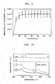
- FIG. 7 is a graph, for different wavenumbers, of the intensity of Raman scattered light according to the number of depositions of metal nanoparticles 13 in a substrate 10 for sensing, according to an exemplary embodiment.
- a liquid phase deposition including immersing the support layer 11 having nanowires 12 formed thereon in a metal nanoparticle precursor solution and heating the metal nanoparticle precursor solution in a convection oven at a temperature of about 90 °C for about one hour, is performed eight times.
- Intensities of Raman scattered light for wavenumbers of about 999 cm -1 , 1022 cm -1 , 1072 cm -1 , 1574 cm -1 are measured from the substrate 10 for sensing after each liquid phase deposition operation is performed.
- the measurement is performed by using 1 nM benzenethiol as a sample solution, using a 0.07 mW laser having a wavelength of 785 nm as a light source, and using Au as the metal nanoparticles 13.
- the intensity of Raman scattered light rapidly increases up to the third deposition for most wavenumbers, and thereafter, the intensity of Raman scattered light is maximized at the fifth deposition. Therefore, the surface-enhanced effect is almost saturated between the third deposition and the eighth deposition.
- FIG. 8 is a graph showing a surface-enhanced effect according to a mean interval between adjacent ones of the plurality of metal nanoparticle clusters 14 in the substrate 10 for sensing, according to an exemplary embodiment.
- the graph of FIG. 8 is a result of simulating a surface-enhanced effect formed between the metal nanoparticle clusters 14 while changing the mean interval between adjacent ones of the plurality of metal nanoparticle clusters 14 from 8 nm to 22 nm by assuming a diameter of each metal nanoparticle 13 formed of Au is 14 nm.
- a standard deviation ⁇ of the mean interval between adjacent ones of the metal nanoparticle clusters 14 is 7 nm.
- the surface-enhanced effect is lowered due to a loss of light to reflection.
- the mean interval between adjacent ones of the metal nanoparticle clusters 14 is too large, light is transmitted without exciting sufficient numbers of the metal nanoparticles 13, thereby lowering the surface-enhanced effect.
- the mean interval between adjacent ones of the metal nanoparticle clusters 14 is appropriate, there is an optimal interaction between light and the metal nanoparticles 13, and most of the light excites the metal nanoparticles 13. For example, when the mean interval between adjacent ones of the plurality of metal nanoparticle clusters 14 is 8 nm to 20 nm, the surface-enhanced effect may be optimal.
- the surface-enhanced effect of the substrate 10 for sensing according to the present exemplary embodiment may also vary according to the length of the perforations 15 through which the light is transmitted or according to a thickness of the metal nanoparticle clusters 14.
- FIG. 9 is a graph showing a surface-enhanced effect according to a thickness of the metal nanoparticle clusters 14 in a substrate 10 for sensing, according to an exemplary embodiment. The graph of FIG.
- the thickness of the plurality of metal nanoparticle clusters 14 may be selected to be between 50 nm and 1 ⁇ m.
- FIG. 10 is a graph showing Raman spectra of various concentrations of samples in a substrate 10 for sensing, according to an exemplary embodiment. For example, measurements are performed by using benzenethiol solutions of which concentrations are I mM, 1 ⁇ M, 1 nM, and 1 pM, respectively, as sample solutions and using Au as the metal nanoparticles 13. Referring to the graph of FIG. 10 , Raman spectra for all concentrations may be clearly seen. Particularly, peaks formed at a certain wavenumber for all concentrations may be seen.
- FIG. 11 is a graph, for different wavenumbers, of an intensity of Raman scattered light according to concentrations of samples in a substrate 10 for sensing, according to an exemplary embodiment.
- intensities of Raman scattered light for wavenumbers of about 999 cm -1 , 1022 cm -1 , 1072 cm -1 , and 1574 cm -1 while changing a concentration of a benzenethiol solution are measured.
- the intensities of Raman scattered light for all the wavenumbers increase.
- FIG. 12 is a graph showing an intensity distribution of a peak of about 1072 cm -1 in a substrate 10 for sensing, according to an exemplary embodiment.
- a substrate 10 for sensing is manufactured on a Si wafer having a four-inch diameter.
- metal clusters 14 formed of Au are formed on the support layer 11 formed of a Si wafer having a four-inch diameter.
- an intensity of a peak formed in a wavenumber of about 1072 cm -1 for a benzenethiol solution of which a concentration is 1 mM is repetitively measured, and a distribution thereof is seen.
- peak intensities in the wavenumber of about 1072 cm -1 are distributed in a relatively narrow region. Therefore, since substrates for sensing 10 may be uniformly manufactured on a four-inch wide-area wafer, the manufacturing cost of each substrate 10 for sensing may be lowered.
- FIG. 13 is a graph showing an intensity distribution of a peak of about 999 cm -1 in a substrate 10 for sensing manufactured on a four-inch wafer
- FIG. 14 is a graph showing an intensity distribution of a peak of about 1022 cm -1 in a substrate 10 for sensing manufactured on a four-inch wafer
- FIG. 15 is a graph showing an intensity distribution of a peak of about 1072 cm -1 in a substrate 10 for sensing manufactured on a wafer of a size of 4 ⁇ 4 mm 2 .
- a benzenethiol solution of which a concentration is 1 mM is used as a sample. Referring to the graphs of FIGS.
- FIG. 16 is a graph showing a relationship between an angle of incident light and an intensity of Raman scattered light in a substrate 10 for sensing, according to an exemplary embodiment.
- a benzenethiol solution of which a concentration is 1 mM is used as a sample, and the angle of the incident light is changed from 0° to 80°.
- the angle of the incident light is measured with respect to a surface of the substrate 10 for sensing. That is, an incident angle of light which is incident at an angle normal to a surface of the substrate 10 for sensing is 0°.
- the intensity of Raman scattered light decreases.
- FIG. 17 is a graph showing Raman spectra of various concentrations of other samples in a substrate 10 for sensing, according to an exemplary embodiment.
- adenine solutions of which concentrations are respectively 10 ⁇ M, 1 ⁇ M, 100 nM, and 10 nM are used as samples.
- an intensity of a sample increases, an intensity of Raman scattered light increases, and a peak in a certain wavenumber may also be seen.
- FIG. 18 is a graph showing a relationship between sample concentration and intensity of Raman scattered light in a substrate 10 for sensing, according to an exemplary embodiment
- FIG. 19 is a graph showing a result of measuring a sample concentration by using a substrate 10 for sensing, according to an exemplary embodiment.
- the sample concentration and the intensity of Raman scattered light are almost proportional to each other.
- a concentration of an adenine solution sample may be correctly measured by using the result of FIG. 18 .
- a substrate 10 for sensing may be manufactured by forming, on the support layer 11, nanowires 12 formed of a material different from that of the support layer 11, and by forming metal nanoparticles 13 on the surfaces of the nanowires 12.
- nanowires or similar structures may be formed by etching the support layer 11.
- FIG. 20 is a schematic perspective view showing a method of manufacturing a substrate 10 for sensing, according to another exemplary embodiment.
- the support layer 11 and a plurality of nanowires 11a formed thereon may be formed by selectively etching an upper surface of a support layer material 11'.
- the support layer 11 and the plurality of nanowires 11a are formed of the same material and may be formed at the same time. Thereafter, as shown in FIGS.
- a plurality of metal nanoparticle clusters 14 including a plurality of conductive metal nanoparticles 13 stacked in a three-dimensional structure may be formed by depositing the plurality of conductive metal nanoparticles 13 on the surfaces of the nanowires 11a.
- the plurality of nanowires 11a may be dissolved in the operations of forming the metal nanoparticle clusters 14 or may be removed after forming the metal nanoparticle clusters 14. In this case, a thickness of the support layer 11 may be much larger than a diameter of the nanowires 11a such that the support layer 11 is not removed.
- FIG. 21 is a schematic perspective view showing a method of manufacturing a substrate 10 for sensing, according to another exemplary embodiment.
- a plurality of parallel trenches 11b may be formed by etching an upper surface of the support layer material 11' in the form of a plurality of parallel straight lines.
- the support layer 11 and walls 11c, formed thereon in the form of a plurality of parallel planes may be formed. Thereafter, as shown in FIGS.
- a plurality of metal nanoparticle clusters 14 including a plurality of conductive metal nanoparticles 13 stacked in a three-dimensional structure may be formed by depositing the plurality of conductive metal nanoparticles 13 on the plurality of walls 11c.
- the plurality of walls 11c may be dissolved in the operations of forming the metal nanoparticle clusters 14 or may be removed after forming the metal nanoparticle clusters 14.
- perforations 15, which are openings in the form of slits formed by the removal of the walls 11c may be formed in the form of a plurality of parallel straight lines.
- This manufactured substrate 10 for sensing may be used as, for example, an SERS substrate but its use is not limited thereto.
- the substrate 10 for sensing may be variously applied to any of various optical measurement methods.
- the substrate 10 for sensing may be applied to fluorescence-based spectroscopy.
- the substrate 10 for sensing since the substrate 10 for sensing has a high light absorption ratio, the substrate 10 for sensing may also be applied to a solar cell and an anti-reflective film.
- a disposable, wearable, handheld, implantable, or desktop sensing platform may be implemented.
- FIG. 22 is a block diagram of an analyzing apparatus 100 including a substrate 10 for sensing, according to an exemplary embodiment.
- the analyzing apparatus 100 may include an illumination optical system 110 including a light source that emits excitation light LE onto the substrate 10 for sensing, a detection optical system 120 including an optical detector that detects light LS scattered from the substrate 10 for sensing, and a signal processor 130 that analyzes a property of a substance of an object by using an signal output from the detection optical system 120.
- the object may be disposed on the substrate 10 for sensing.
- the signal processor 130 may analyze a property of a substance of the object by analyzing an intensity and a spectrum of the light LS scattered from the substrate 10 for sensing.
- the signal processor 130 may be configured to control an operation of the detection optical system 120 according to circumstances.
- the analyzing apparatus 100 may further include a memory 140 that stores a program, data, and the like used for the processing of the signal processor 130 and a user interface 150 that provides a result analyzed by the signal processor 130 to a user.
- the analyzing apparatus 100 may further include an amplifier that amplifies a signal detected by the detection optical system 120.
- the analyzing apparatus 100 may be a biometric information analyzing apparatus that measures and analyzes a biometric component by a non-invasive method.
- the analyzing apparatus 100 may analyze substances included in tissue or blood of the object or components thereof. Raman spectroscopy may be used to analyze a property of a substance of the object.
- Raman spectroscopy takes advantage of the phenomenon by which an energy state is shifted when light of a single wavelength is scattered through an interaction with molecular vibrations of substances forming an object.
- the excitation light LE emitted from the illumination optical system 110 is scattered by a molecular structure in the object and is output from the object in the form of wavelength-converted scattered light LS.
- the scattered light LS i.e., a biometric optical signal, includes various spectra of which wavelength-converted degrees are different according to molecular states of the object.
- a detected Raman signal includes a wavelength shift moved from a wavelength of incident light, and the wavelength shift may include information related to molecular vibrations of a substance, e.g., information regarding a molecular structure, a bonding shape, and the like, and may include information regarding a functional group.
- the intercellular fluid or blood of a patient may include glucose, urea, ceramide, keratin, collagen, and the like.
- Glucose for example, may have Raman shift values corresponding to wavenumbers of about 436.4 cm -1 , 1065 cm -1 , 1126.4 cm -1 , 525.7 cm -1 .
- collagen may exhibit Raman shifts of about 855 cm -1 and 936 cm -1 .
- urea may exhibit a Raman shift of about 1000 cm -1 .
- the signal processor 130 may obtain a distribution amount of each substance from the intensity of a spectral peak at a point at which a wavelength is shifted by the Raman shift corresponding to each substance, from a wavelength of the excitation light LE. For example, if the intensity of spectrum peaks is high at positions at which a wavelength is shifted, from a wavenumber of incident light, by wavenumbers of about 436.4 cm -1 , 1065 cm -1 , 1126.4 cm -1 , 525.7 cm -1 , this may indicate that the distribution amount of glucose is large.
- the signal processor 130 may analyze distribution amounts of substances included in the skin of a patient (the object) from a Raman signal as described above and may thereby diagnose a health state of the patient.
- the substrate 10 for sensing may improve detection sensitivity of the analyzing apparatus 100 by enhancing a magnitude of the scattered light LS output from the object.
- the signal processor 130 may generate a control signal used to control a general operation of the analyzing apparatus 100.
- the signal processor 130 may process an analyzed result as an image signal such that the analyzed result is displayed on a display of the user interface 150.
- the signal processor 130 may transmit a control signal to the illumination optical system 110 and the detection optical system 120 according to an input from the user interface 150.
- the signal processor 130 may be implemented by a microprocessor or the like.
- the user interface 150 is an interface between the analyzing apparatus 100 and the user and/or other external equipment and may include an input unit and a display.
- the memory 140 may store a program for processing and controlling the signal processor 130 and may store input/output data.
- the memory 140 may store a lookup table of correlations between spectral peak values and amounts of substances, to enable the signal processor to quantitatively determine an amount of a substance from an intensity of a Raman spectral peak.
- the memory 140 may include at least one type of storage medium from among a flash memory type memory, a hard disk type memory, a multimedia card micro type memory, a card type memory (e.g., a secure digital (SD) or extreme digital (XD) memory), a random access memory (RAM), a read-only memory (ROM), an electrically erasable programmable read-only memory (EEPROM), a programmable read-only memory (PROM), a magnetic memory, a magnetic disc, and an optical disc, as well as another type of memory as would be understood by one of skill in the art.
- a flash memory type memory e.g., a secure digital (SD) or extreme digital (XD) memory
- RAM random access memory
- ROM read-only memory
- EEPROM electrically erasable programmable read-only memory
- PROM programmable read-only memory
- the analyzing apparatus 100 may further include a communication interface.
- an analyzed result may be transmitted to other external equipment through the communication interface.
- the external equipment may be medical equipment using analyzed biometric information, a printer for printing a result, or a display apparatus that displays an analysis result.
- the external equipment may be a smartphone, a cellular phone, a personal digital assistant (PDA), a laptop computer, a personal computer (PC), a wearable device, or another mobile or non-mobile computing device and is not limited thereto.
- An apparatus may include a processor, a memory for storing and executing program data, a permanent storage such as a disk drive, a communication port for communicating with an external device, and a user interface, such as a touch panel, a key, and a button.
- Methods implemented via a software module or an algorithm may be stored in a non-transitory computer-readable recording medium in the form of computer-readable codes or program instructions executable in the processor.
- Examples of the computer-readable recording medium include magnetic storage media (e.g., ROM, RAM, floppy disks, hard disks, etc.) and optical recording media (e.g., CD-ROMs, digital versatile discs (DVDs), etc.).
- the computer-readable recording medium can also be distributed over network coupled computer systems so that the computer-readable code is stored and executed in a distributed fashion. The media can be read by a computer, stored in the memory, and executed by the processor.
Abstract
Description
- Apparatuses and methods consistent with exemplary embodiments relate to a substrate for sensing, a method of manufacturing the substrate, and an analyzing apparatus including the substrate, and more particularly, to a surface-enhanced Raman scattering (SERS) substrate, a method of manufacturing a highly uniform SERS substrate with a wide area, and a biometric information analyzing apparatus including the SERS substrate.
- Raman spectroscopy may be used to analyze components of various materials by measuring the inelastic scattering which occurs inside an object due to an excitation by light incident on the object. When light is incident on a sample to be measured, inelastically scattered light, of a wavelength which is different from the wavelength of the incident light, can be detected and measured. The resultant wavelength shift between the incident light and the scattered light is referred to as a Raman shift, and this shift indicates the molecular vibrational or rotational energy state of the object. Since it is known that an intensity of Raman scattered light directly corresponds to the concentration of a target molecule, Raman spectroscopy is very useful for molecular analysis.
- Particularly, since a surface-enhanced Raman scattering (SERS) phenomenon was discovered, in which the Raman signal of molecules adsorbed by a roughly surface-treated metal substrate increases significantly, the weakness of conventional Raman spectroscopy, which has a lower detection sensitivity due to the very small signal strength of Raman scattered light, has been improved. In order to clarify the principle of SERS, much research has been conducted. For example, it is predicted that, when a laser beam is incident on a metal, an excitation of surface plasmons is concentrated in a certain region according to the structure of the surface of the metal, thereby inducing SERS. In addition, it is also predicted that the electromagnetic interaction between the metal and molecules adsorbed by the metal contributes to SERS.
- According to an aspect of an exemplary embodiment, a substrate for sensing includes: a support layer; a plurality of metal nanoparticle clusters arranged on the support layer; and a plurality of perforations arranged among the plurality of metal nanoparticle clusters such that incident light is delivered from an upper portion of the plurality of metal nanoparticle clusters to a lower portion of the plurality of metal nanoparticle clusters, wherein each of the plurality of metal nanoparticle clusters includes a plurality of conductive metal nanoparticles stacked in a three-dimensional structure.
- The support layer may be a semiconductor wafer.
- The metal nanoparticles may include at least one conductive metal selected from gold (Au), silver (Ag), copper (Cu), and aluminum (Al).
- The plurality of metal nanoparticle clusters may extend in a vertical direction from a surface of the support layer.
- A thickness of the plurality of metal nanoparticle clusters may be 50 nm to 1 µm.
- The plurality of perforations may extend to a surface of the support layer, such that incident light is transmitted therethrough to the surface of the support layer.
- A mean diameter of the metal nanoparticles may be 10 nm to 20 nm.
- A mean interval between adjacent ones of the plurality of metal nanoparticle clusters may be 8 nm to 20 nm.
- According to an aspect of another exemplary embodiment, an analyzing apparatus includes the substrate for sensing.
- According to an aspect of another exemplary embodiment, a method of manufacturing a substrate for sensing includes: forming a plurality of nanowires on a support layer; forming a plurality of metal nanoparticle clusters each including a plurality of conductive metal nanoparticles stacked in a three-dimensional structure, by depositing the plurality of conductive metal nanoparticles on surfaces of the plurality of nanowires; and forming a plurality of perforations among the plurality of metal nanoparticle clusters by at least partially removing the plurality of nanowires.
- The plurality of nanowires may be formed of silicon (Si), indium phosphide (InP), gallium nitride (GaN), or zinc oxide (ZnO).
- The forming of the plurality of nanowires may include: coating a seed layer of a nanowire material on the support layer; placing the support layer in a solution including a precursor of the nanowire material; and removing the support layer from the solution and heat-treating the support layer.
- The forming of the plurality of metal nanoparticle clusters may include: a liquid phase deposition operation of placing the support layer having the plurality of nanowires formed thereon in a metal nanoparticle precursor solution and heating the metal nanoparticle precursor solution with the support layer therein; and a cleansing operation of cleansing the support layer.
- The forming of the plurality of metal nanoparticle clusters may include repeating the liquid phase deposition operation a plurality of times.
- The at least partially removing the plurality of nanowires may be performed during the liquid phase deposition operation.
- The metal nanoparticle precursor solution may include a solvent for dissolving the plurality of nanowires.
- The plurality of perforations may extend to a surface of the support layer, such that the plurality of perforations transmit incident light to the surface of the support layer.
- According to an aspect of another exemplary embodiment, a method of manufacturing a substrate for sensing includes: partially removing a support layer material, thereby forming a support layer and a plurality of elements extending from a surface thereof, wherein the plurality of elements comprise one of a plurality of nanowires and a plurality of walls; forming a plurality of metal nanoparticle clusters each including a plurality of conductive metal nanoparticles stacked in a three-dimensional structure, by depositing the plurality of conductive metal nanoparticles on surfaces of the plurality of elements; and forming a plurality of perforations among the plurality of metal nanoparticle clusters by at least partially removing the plurality of elements.
- These and/or other exemplary aspects and advantages will become apparent and more readily appreciated from the following description of exemplary embodiments, taken in conjunction with the accompanying drawings in which:
-
FIGS. 1A to 1E are schematic cross-sectional views illustrating a process of manufacturing a substrate for sensing, according to an exemplary embodiment; -
FIG. 2A illustrates a scanning electron microscope (SEM) image of metal nanoparticles deposited on a nanowire in the operation shown inFIG. 1B ; -
FIG. 2B illustrates an SEM image of metal nanoparticles stacked in a three-dimensional structure in the operation shown inFIG. 1E ; -
FIG. 3 illustrates energy dispersive spectrometry (EDS) data showing a change in components of a substrate for sensing according to the number of depositions of metal nanoparticles; -
FIG. 4 is a graph showing a change in components of a substrate for sensing according to the number of depositions of metal nanoparticles; -
FIG. 5 is a perspective view showing a schematic configuration of a substrate for sensing, according to an exemplary embodiment; -
FIG. 6 is a cross-sectional view showing a schematic configuration of a substrate for sensing, according to an exemplary embodiment; -
FIG. 7 is a graph showing, for different wavenumbers, an intensity of Raman scattered light according to the number of depositions of metal nanoparticles in a substrate for sensing, according to an exemplary embodiment; -
FIG. 8 is a graph showing a surface-enhanced effect according to a mean interval between a plurality of metal nanoparticle clusters in a substrate for sensing, according to an exemplary embodiment; -
FIG. 9 is a graph showing a surface-enhanced effect according to a thickness of metal nanoparticle clusters in a substrate for sensing, according to an exemplary embodiment; -
FIG. 10 is a graph showing Raman spectra of various concentrations of samples in a substrate for sensing, according to an exemplary embodiment; -
FIG. 11 is a graph showing, for different wavenumbers, an intensity of Raman scattered light according to concentrations of samples in a substrate for sensing, according to an exemplary embodiment; -
FIG. 12 is a graph showing an intensity distribution of a peak of about 1072 cm-1 in a substrate for sensing, according to an exemplary embodiment; -
FIG. 13 is a graph showing an intensity distribution of a peak of about 999 cm-1 in a substrate for sensing manufactured on a four-inch wafer; -
FIG. 14 is a graph showing an intensity distribution of a peak of about 1022 cm-1 in a substrate for sensing manufactured on a four-inch wafer; -
FIG. 15 is a graph showing an intensity distribution of a peak of about 1072 cm-1 in a substrate for sensing manufactured on a wafer of a size of 4×4 mm2; -
FIG. 16 is a graph showing a relationship between an angle of incident light and an intensity of Raman scattered light in the substrate for sensing, according to an exemplary embodiment; -
FIG. 17 is a graph showing Raman spectra of various concentrations of other samples in the substrate for sensing, according to an exemplary embodiment; -
FIG. 18 is a graph showing a relationship between sample concentration and intensity of Raman scattered light in a substrate for sensing, according to an exemplary embodiment; -
FIG. 19 is a graph showing a result of measuring a sample concentration by using a substrate for sensing, according to an exemplary embodiment; -
FIG. 20 is a schematic perspective view showing a method of manufacturing a substrate for sensing, according to another exemplary embodiment; -
FIG. 21 is a schematic perspective view showing a method of manufacturing a substrate for sensing, according to another exemplary embodiment; and -
FIG. 22 is a block diagram of an analyzing apparatus including a substrate for sensing, according to an exemplary embodiment. - Hereinafter, exemplary embodiments of a substrate for sensing, a method of manufacturing the substrate, and an analyzing apparatus including the substrate are described in detail with reference to the accompanying drawings. In the drawings, like reference numerals refer to like elements, and the sizes of components may be exaggerated for convenience and clarity of description. In addition, the exemplary embodiments to be described below are only illustrative, and various modifications may be made from the exemplary embodiments. In addition, in a layer structure to be described below, the expression "on an upper part of" or "on" may include the meaning of not only located directly on/under/left/right but also located indirectly on/under/left/right.
- As used herein, the term "and/or" includes any and all combinations of one or more of the associated listed items. Expressions such as "at least one of," when preceding a list of elements, modify the entire list of elements and do not modify the individual elements of the list.
-
FIGS. 1A to 1E are schematic cross-sectional views illustrating a process of manufacturing a substrate for sensing, according to an exemplary embodiment. - Referring to
FIG. 1A , a plurality ofnanowires 12 may be formed on asupport layer 11. Thesupport layer 11 may be a semiconductor wafer used in a general semiconductor manufacturing process. For example, thesupport layer 11 may be a semiconductor wafer formed of silicon (Si), germanium (Ge), gallium arsenide (GaAs), gallium phosphide (GaP), or the like. - The plurality of
nanowires 12 may extend vertically from thesupport layer 11. Thenanowires 12 may be formed of a material which is removable in post-processing or does which does not affect Raman scattering even if the material is not removed. For example, thenanowires 12 may be formed of a material such as Si, indium phosphide (InP), gallium nitride (GaN), zinc oxide (ZnO), or the like. - The
nanowires 12 may be formed by coating aseed layer 12a of a nanowire material on thesupport layer 11, disposing thesupport layer 11 in a solution including a precursor of the nanowire material, pulling thesupport layer 11 from the solution, and then heat-treating thesupport layer 11. - For example, when the
nanowires 12 are to be ZnO nanowires, a ZnO seed solution including 5 mM-concentration of zinc acetate dihydrate dissolved in ethanol is coated on thesupport layer 11. Thereafter, thesupport layer 11 and the ZnO seed solution are heat-treated on a hot plate at a temperature of about 350 °C for about 20 minutes such that theseed layer 12a clearly adheres onto thesupport layer 11. Thereafter, thesupport layer 11 is immersed in a ZnO precursor solution, and thesupport layer 11 is heated in a convection oven at a temperature of about 95 °C for about 2.5 hours. For example, the ZnO precursor solution may be a solution including zinc nitrate hexahydrate of a 25 mM concentration, hexamethylenetetramine (HMTA) of a 25 mM concentration, and poly ether imide (PEI) of a 5 mM concentration in de-ionized (DI) water. Thereafter, when thesupport layer 11 is pulled from the ZnO precursor solution, the ZnO precursor solution remaining on thesupport layer 11 is cleansed out by using DI water, thesupport layer 11 is heat-treated on a hot plate at a temperature of about 350 °C for about 20 minutes, and the ZnO nanowires may be formed on thesupport layer 11.
Alternately, thenanowires 12 may be formed by any of various other methods. - Referring to
FIG. 1B , a plurality ofconductive metal nanoparticles 13 may be stacked in a three-dimensional structure by depositing the plurality ofconductive metal nanoparticles 13 on surfaces of the plurality ofnanowires 12. Themetal nanoparticles 13 may include a metal having good conductivity, for example, gold (Au), silver (Ag), copper (Cu), and aluminum (Al). In addition, as shown inFIG. 1E , a plurality ofmetal nanoparticle clusters 14 including a plurality ofconductive metal nanoparticles 13 stacked in a three-dimensional structure may be formed by repeating the operation of depositing the plurality ofconductive metal nanoparticles 13 on surfaces of the plurality ofnanowires 12, as shown inFIGS. 1C to 1E . - For example, the plurality of
metal nanoparticle clusters 14 may be formed by a liquid phase deposition method of immersing thesupport layer 11, having the plurality ofnanowires 12 formed thereon, in a metal nanoparticle precursor solution and heating the same. In more detail, thesupport layer 11 having the plurality ofnanowires 12 formed thereon is immersed in a metal nanoparticle precursor solution, and the metal nanoparticle precursor solution may be heated in a convection oven at a temperature of about 90 °C for about one hour. This liquid phase deposition operation may be repeated a plurality of times until a plurality ofconductive metal nanoparticles 13 are concentrated to form themetal nanoparticle clusters 14. A mean diameter of themetal nanoparticles 13 formed by the liquid phase deposition operation may be, for example, 10 nm to 20 nm. - For example,
FIG. 2A illustrates a scanning electron microscope (SEM) image ofmetal nanoparticles 13 deposited onnanowires 12, as shown in the operation ofFIG. 1B . Referring toFIG. 2A , themetal nanoparticles 13 are deposited on surfaces of thenanowires 12 at a relatively low density. In addition,FIG. 2B illustrates an SEM image ofmetal nanoparticles 13 stacked in three-dimensional structures, as shown in the operation ofFIG. 1E . For example,FIG. 2B illustrates a case in which the liquid phase deposition operation described above is repeated eight times. Referring toFIG. 2B ,metal nanoparticle clusters 14 are formed by very densely depositing a plurality ofmetal nanoparticles 13. - As the liquid phase deposition operation is repeated, the
nanowire 12 may gradually dissolve and disappear due to an acidic component of the metal nanoparticle precursor solution. Alternatively, a solvent for dissolving thenanowires 12 may be intentionally included in the metal nanoparticle precursor solution. Referring toFIG. 2B , when the liquid phase deposition operation is repeated eight times, only themetal nanoparticle clusters 14 remain, and thenanowires 12 have almost entirely disappeared. - For example,
FIG. 3 illustrates energy dispersive spectrometry (EDS) data showing a change in components of a substrate for sensing according to the number of depositions ofmetal nanoparticles 13, andFIG. 4 is a graph showing the same. In the example ofFIGS. 3 and4 , Si is used for thesupport layer 11, ZnO is used for thenanowires 12, and Au is used for themetal nanoparticles 13. Referring toFIGS. 3 and4 , in initial stages, a Zn component is almost 50 at%, and an Au component comprises the least at%. However, as the number of depositions increases, the Zn component gradually decreases, and Si and Au components gradually increase. When the number of depositions is eight, the Zn component has almost disappeared, and the Au component comprises the greatest at%. - Finally, the
support layer 11 having themetal nanoparticle cluster 14 formed thereon may be cleansed. For example, salt and carbon compounds remaining on the substrate for sensing may be removed by being cleansed with DI water and ethanol. Then, asubstrate 10 for sensing having the plurality ofmetal nanoparticle clusters 14 densely arranged on thesupport layer 11 may be completed. - Although it has been described that the
metal nanoparticle clusters 14 are formed by a liquid phase deposition method, this is only exemplary. Alternately, for example, besides the liquid phase deposition method, themetal nanoparticle cluster 14 may be formed by depositingmetal nanoparticles 13 on the surface of thenanowire 12 by sputtering or evaporation. In this case, thenanowire 12 remaining on thesupport layer 11 may be removed through a separate process. For example, thenanowires 12 remaining on thesupport layer 11 may be at least partially removed, and then thesupport layer 11 may be cleansed. -
FIG. 5 is a perspective view showing a schematic configuration of asubstrate 10 for sensing, according to an exemplary embodiment, and referring toFIG. 5 , a plurality ofmetal nanoparticle clusters 14 may be densely, three-dimensionally arranged on thesupport layer 11. Eachmetal nanoparticle cluster 14 may include a plurality ofconductive metal nanoparticles 13 stacked in a three-dimensional structure. As described above, a plurality ofconductive metal nanoparticles 13 are densely formed on the surface of ananowire 12, and the plurality ofconductive metal nanoparticles 13 formed on the surface of onenanowire 12 form onemetal nanoparticle cluster 14. The plurality ofmetal nanoparticle clusters 14 each extend in a vertical direction with respect to a surface of thesupport layer 11. Meanwhile, theseed layer 12a of the nanowire material may at least partially remain on the surface of thesupport layer 11. - In addition,
FIG. 6 is a cross-sectional view showing a schematic configuration of asubstrate 10 for sensing, according to an exemplary embodiment. Referring toFIG. 6 , thesubstrate 10 for sensing may include a plurality offine perforations 15 which are openings which remain between adjacent ones of the plurality ofmetal nanoparticle clusters 14 upon removal of thenanowires 12. The plurality offine perforations 15, through which light may pass may be, for example, spaces remaining in positions where the plurality ofnanowires 12 have been dissolved. As discussed above, as the plurality ofconductive metal nanoparticles 13 formed on the surface of ananowire 12 increase to form ametal nanoparticle cluster 14, thenanowire 12 is gradually dissolved, thereby leaving aplurality perforation 15. - The plurality of
perforations 15 allow light to be transmitted from an upper part of the plurality ofmetal nanoparticle clusters 14 to a lower part thereof. As shown inFIG. 6 , light incident on an upper part of thesubstrate 10 for sensing may be transmitted along theperforations 15 between themetal nanoparticle clusters 14 and may thereby reach the bottom of thesubstrate 10 for sensing. In other words, light may reach the surface of thesupport layer 11 by being transmitted between themetal nanoparticle clusters 14 via theperforations 15. In this way, as the light is transmitted along a relatively long, three-dimensionally formed path, the light may excite a large number ofconductive metal nanoparticles 13 located between an upper part of ametal nanoparticle cluster 14 and a lower part thereof. Therefore, thesubstrate 10 for sensing according to the present exemplary embodiment may further increase a surface-enhanced effect. Since thesubstrate 10 for sensing according to the present exemplary embodiment sufficiently absorbs light through theperforations 15 among themetal nanoparticle clusters 14, thesubstrate 10 for sensing has a good light use efficiency and may appear as an almost perfect black color. - The surface-enhanced effect of the
substrate 10 for sensing according to the present exemplary embodiment may vary according to a density ofconductive metal nanoparticles 13.FIG. 7 is a graph, for different wavenumbers, of the intensity of Raman scattered light according to the number of depositions ofmetal nanoparticles 13 in asubstrate 10 for sensing, according to an exemplary embodiment. For example, a liquid phase deposition, including immersing thesupport layer 11 havingnanowires 12 formed thereon in a metal nanoparticle precursor solution and heating the metal nanoparticle precursor solution in a convection oven at a temperature of about 90 °C for about one hour, is performed eight times. Intensities of Raman scattered light for wavenumbers of about 999 cm-1, 1022 cm-1, 1072 cm-1, 1574 cm-1 are measured from thesubstrate 10 for sensing after each liquid phase deposition operation is performed. The measurement is performed by using 1 nM benzenethiol as a sample solution, using a 0.07 mW laser having a wavelength of 785 nm as a light source, and using Au as themetal nanoparticles 13. Referring to the graph ofFIG. 7 , the intensity of Raman scattered light rapidly increases up to the third deposition for most wavenumbers, and thereafter, the intensity of Raman scattered light is maximized at the fifth deposition. Therefore, the surface-enhanced effect is almost saturated between the third deposition and the eighth deposition. - In addition, the surface-enhanced effect of the
substrate 10 for sensing according to the present exemplary embodiment may also vary according to the size of theperforations 15 or the intervals among the plurality ofmetal nanoparticle clusters 14.FIG. 8 is a graph showing a surface-enhanced effect according to a mean interval between adjacent ones of the plurality ofmetal nanoparticle clusters 14 in thesubstrate 10 for sensing, according to an exemplary embodiment. The graph ofFIG. 8 is a result of simulating a surface-enhanced effect formed between themetal nanoparticle clusters 14 while changing the mean interval between adjacent ones of the plurality ofmetal nanoparticle clusters 14 from 8 nm to 22 nm by assuming a diameter of eachmetal nanoparticle 13 formed of Au is 14 nm. Herein, it is assumed that a standard deviation σ of the mean interval between adjacent ones of themetal nanoparticle clusters 14 is 7 nm. - Referring to
FIG. 8 , when the mean interval between adjacent ones of themetal nanoparticle clusters 14 is too small, the surface-enhanced effect is lowered due to a loss of light to reflection. When the mean interval between adjacent ones of themetal nanoparticle clusters 14 is too large, light is transmitted without exciting sufficient numbers of themetal nanoparticles 13, thereby lowering the surface-enhanced effect. When the mean interval between adjacent ones of themetal nanoparticle clusters 14 is appropriate, there is an optimal interaction between light and themetal nanoparticles 13, and most of the light excites themetal nanoparticles 13. For example, when the mean interval between adjacent ones of the plurality ofmetal nanoparticle clusters 14 is 8 nm to 20 nm, the surface-enhanced effect may be optimal. - In addition, the surface-enhanced effect of the
substrate 10 for sensing according to the present exemplary embodiment may also vary according to the length of theperforations 15 through which the light is transmitted or according to a thickness of themetal nanoparticle clusters 14.FIG. 9 is a graph showing a surface-enhanced effect according to a thickness of themetal nanoparticle clusters 14 in asubstrate 10 for sensing, according to an exemplary embodiment. The graph ofFIG. 9 is a result of simulating a surface-enhanced effect formed between themetal nanoparticle clusters 14 while varying the thickness themetal nanoparticle clusters 14 from 0 nm to 600 nm and assuming that a diameter of eachmetal nanoparticle 13 formed of Au is 14 nm, that a mean interval between adjacent ones of themetal nanoparticle clusters 14 is 15 nm, and that a standard deviation σ of the mean interval between adjacent ones of themetal nanoparticle clusters 14 is 7 nm. Referring toFIG. 9 , the surface-enhanced effect increases until the thickness of themetal nanoparticle clusters 14 is about 300 nm, and thereafter, the surface-enhanced effect is saturated. Therefore, the thickness of the plurality ofmetal nanoparticle clusters 14 may be selected to be between 50 nm and 1 µm. -
FIG. 10 is a graph showing Raman spectra of various concentrations of samples in asubstrate 10 for sensing, according to an exemplary embodiment. For example, measurements are performed by using benzenethiol solutions of which concentrations are I mM, 1 µM, 1 nM, and 1 pM, respectively, as sample solutions and using Au as themetal nanoparticles 13. Referring to the graph ofFIG. 10 , Raman spectra for all concentrations may be clearly seen. Particularly, peaks formed at a certain wavenumber for all concentrations may be seen. -
FIG. 11 is a graph, for different wavenumbers, of an intensity of Raman scattered light according to concentrations of samples in asubstrate 10 for sensing, according to an exemplary embodiment. For example, intensities of Raman scattered light for wavenumbers of about 999 cm-1, 1022 cm-1, 1072 cm-1, and 1574 cm-1 while changing a concentration of a benzenethiol solution are measured. Referring to the graph ofFIG. 11 , as the concentration of the benzenethiol solution increases, the intensities of Raman scattered light for all the wavenumbers increase. - According to the present exemplary embodiment, since a plurality of dense
metal nanoparticle clusters 14 may be formed uniformly, substrates for sensing may be relatively simply manufactured on a large-area wafer.FIG. 12 is a graph showing an intensity distribution of a peak of about 1072 cm-1 in asubstrate 10 for sensing, according to an exemplary embodiment. In the example ofFIG. 12 , asubstrate 10 for sensing is manufactured on a Si wafer having a four-inch diameter. In other words,metal clusters 14 formed of Au are formed on thesupport layer 11 formed of a Si wafer having a four-inch diameter. By using thissubstrate 10 for sensing, an intensity of a peak formed in a wavenumber of about 1072 cm-1 for a benzenethiol solution of which a concentration is 1 mM is repetitively measured, and a distribution thereof is seen. Referring toFIG. 12 , peak intensities in the wavenumber of about 1072 cm-1 are distributed in a relatively narrow region. Therefore, since substrates for sensing 10 may be uniformly manufactured on a four-inch wide-area wafer, the manufacturing cost of eachsubstrate 10 for sensing may be lowered. - In addition,
FIG. 13 is a graph showing an intensity distribution of a peak of about 999 cm-1 in asubstrate 10 for sensing manufactured on a four-inch wafer,FIG. 14 is a graph showing an intensity distribution of a peak of about 1022 cm-1 in asubstrate 10 for sensing manufactured on a four-inch wafer, andFIG. 15 is a graph showing an intensity distribution of a peak of about 1072 cm-1 in asubstrate 10 for sensing manufactured on a wafer of a size of 4×4 mm2. In the examples ofFIGS. 13 to 15 , a benzenethiol solution of which a concentration is 1 mM is used as a sample. Referring to the graphs ofFIGS. 13 and 14 , relatively uniform characteristics are seen even for the peak of about 999 cm-1 and the peak of about 1022 cm-1. Particularly, referring to the graph ofFIG. 15 , as a size of a wafer is small, uniformity further increases, and thus peak intensities are distributed in a very narrow region, thereby significantly reducing a relative standard deviation (RSD). -
FIG. 16 is a graph showing a relationship between an angle of incident light and an intensity of Raman scattered light in asubstrate 10 for sensing, according to an exemplary embodiment. In the example ofFIG. 16 , a benzenethiol solution of which a concentration is 1 mM is used as a sample, and the angle of the incident light is changed from 0° to 80°. Herein, the angle of the incident light is measured with respect to a surface of thesubstrate 10 for sensing. That is, an incident angle of light which is incident at an angle normal to a surface of thesubstrate 10 for sensing is 0°. As shown in the graph ofFIG. 16 , as the incident angle increases, the intensity of Raman scattered light decreases. -
FIG. 17 is a graph showing Raman spectra of various concentrations of other samples in asubstrate 10 for sensing, according to an exemplary embodiment. In the example ofFIG. 17 , adenine solutions of which concentrations are respectively 10 µM, 1 µM, 100 nM, and 10 nM are used as samples. Referring to the graph ofFIG. 17 , as an intensity of a sample increases, an intensity of Raman scattered light increases, and a peak in a certain wavenumber may also be seen. -
FIG. 18 is a graph showing a relationship between sample concentration and intensity of Raman scattered light in asubstrate 10 for sensing, according to an exemplary embodiment, andFIG. 19 is a graph showing a result of measuring a sample concentration by using asubstrate 10 for sensing, according to an exemplary embodiment. Referring to the graph ofFIG. 18 , the sample concentration and the intensity of Raman scattered light are almost proportional to each other. In addition, referring to the graph ofFIG. 19 , a concentration of an adenine solution sample may be correctly measured by using the result ofFIG. 18 . - It has been described that a
substrate 10 for sensing may be manufactured by forming, on thesupport layer 11,nanowires 12 formed of a material different from that of thesupport layer 11, and by formingmetal nanoparticles 13 on the surfaces of thenanowires 12. However, alternately, nanowires or similar structures may be formed by etching thesupport layer 11. - For example,
FIG. 20 is a schematic perspective view showing a method of manufacturing asubstrate 10 for sensing, according to another exemplary embodiment. Referring toFIG. 20 , thesupport layer 11 and a plurality ofnanowires 11a formed thereon may be formed by selectively etching an upper surface of a support layer material 11'. In this case, thesupport layer 11 and the plurality ofnanowires 11a are formed of the same material and may be formed at the same time. Thereafter, as shown inFIGS. 1A to 1E , a plurality ofmetal nanoparticle clusters 14 including a plurality ofconductive metal nanoparticles 13 stacked in a three-dimensional structure may be formed by depositing the plurality ofconductive metal nanoparticles 13 on the surfaces of thenanowires 11a. The plurality ofnanowires 11a may be dissolved in the operations of forming themetal nanoparticle clusters 14 or may be removed after forming themetal nanoparticle clusters 14. In this case, a thickness of thesupport layer 11 may be much larger than a diameter of thenanowires 11a such that thesupport layer 11 is not removed. - In addition,
FIG. 21 is a schematic perspective view showing a method of manufacturing asubstrate 10 for sensing, according to another exemplary embodiment. Referring toFIG. 21 , a plurality ofparallel trenches 11b may be formed by etching an upper surface of the support layer material 11' in the form of a plurality of parallel straight lines. In this way, thesupport layer 11 andwalls 11c, formed thereon in the form of a plurality of parallel planes, may be formed. Thereafter, as shown inFIGS. 1B to 1E , a plurality ofmetal nanoparticle clusters 14 including a plurality ofconductive metal nanoparticles 13 stacked in a three-dimensional structure may be formed by depositing the plurality ofconductive metal nanoparticles 13 on the plurality ofwalls 11c. The plurality ofwalls 11c may be dissolved in the operations of forming themetal nanoparticle clusters 14 or may be removed after forming themetal nanoparticle clusters 14. In this case, perforations 15, which are openings in the form of slits formed by the removal of thewalls 11c, may be formed in the form of a plurality of parallel straight lines. - This manufactured
substrate 10 for sensing may be used as, for example, an SERS substrate but its use is not limited thereto. Thesubstrate 10 for sensing may be variously applied to any of various optical measurement methods. For example, thesubstrate 10 for sensing may be applied to fluorescence-based spectroscopy. In addition, since thesubstrate 10 for sensing has a high light absorption ratio, thesubstrate 10 for sensing may also be applied to a solar cell and an anti-reflective film. In addition, by using thesubstrate 10 for sensing according to the present exemplary embodiment, a disposable, wearable, handheld, implantable, or desktop sensing platform may be implemented. - For example,
FIG. 22 is a block diagram of an analyzingapparatus 100 including asubstrate 10 for sensing, according to an exemplary embodiment. Referring toFIG. 22 , the analyzingapparatus 100 according to an exemplary embodiment may include an illuminationoptical system 110 including a light source that emits excitation light LE onto thesubstrate 10 for sensing, a detectionoptical system 120 including an optical detector that detects light LS scattered from thesubstrate 10 for sensing, and asignal processor 130 that analyzes a property of a substance of an object by using an signal output from the detectionoptical system 120. Although not shown, the object may be disposed on thesubstrate 10 for sensing. Thesignal processor 130 may analyze a property of a substance of the object by analyzing an intensity and a spectrum of the light LS scattered from thesubstrate 10 for sensing. Thesignal processor 130 may be configured to control an operation of the detectionoptical system 120 according to circumstances. - In addition, the analyzing
apparatus 100 may further include amemory 140 that stores a program, data, and the like used for the processing of thesignal processor 130 and auser interface 150 that provides a result analyzed by thesignal processor 130 to a user. Although not shown, the analyzingapparatus 100 may further include an amplifier that amplifies a signal detected by the detectionoptical system 120. - The analyzing
apparatus 100 may be a biometric information analyzing apparatus that measures and analyzes a biometric component by a non-invasive method. For example, the analyzingapparatus 100 may analyze substances included in tissue or blood of the object or components thereof. Raman spectroscopy may be used to analyze a property of a substance of the object. - Raman spectroscopy takes advantage of the phenomenon by which an energy state is shifted when light of a single wavelength is scattered through an interaction with molecular vibrations of substances forming an object. The excitation light LE emitted from the illumination
optical system 110 is scattered by a molecular structure in the object and is output from the object in the form of wavelength-converted scattered light LS. The scattered light LS, i.e., a biometric optical signal, includes various spectra of which wavelength-converted degrees are different according to molecular states of the object. A detected Raman signal includes a wavelength shift moved from a wavelength of incident light, and the wavelength shift may include information related to molecular vibrations of a substance, e.g., information regarding a molecular structure, a bonding shape, and the like, and may include information regarding a functional group. - According to a molecular component of the object, a Raman peak on a Raman spectrum appears differently. For example, the intercellular fluid or blood of a patient (i.e. the object) may include glucose, urea, ceramide, keratin, collagen, and the like. Glucose, for example, may have Raman shift values corresponding to wavenumbers of about 436.4 cm-1, 1065 cm-1, 1126.4 cm-1, 525.7 cm-1. In addition, collagen may exhibit Raman shifts of about 855 cm-1 and 936 cm-1. In addition, urea may exhibit a Raman shift of about 1000 cm-1.
- The
signal processor 130 may obtain a distribution amount of each substance from the intensity of a spectral peak at a point at which a wavelength is shifted by the Raman shift corresponding to each substance, from a wavelength of the excitation light LE. For example, if the intensity of spectrum peaks is high at positions at which a wavelength is shifted, from a wavenumber of incident light, by wavenumbers of about 436.4 cm-1, 1065 cm-1, 1126.4 cm-1, 525.7 cm-1, this may indicate that the distribution amount of glucose is large. In addition, if the intensity of spectrum peaks is high at positions at which a wavelength is shifted, from the wavenumber of the incident light by wavenumbers of about 855 cm-1 and 936 cm-1, this may indicate that the distribution amount of collagen is large. - The
signal processor 130 may analyze distribution amounts of substances included in the skin of a patient (the object) from a Raman signal as described above and may thereby diagnose a health state of the patient. Thesubstrate 10 for sensing may improve detection sensitivity of the analyzingapparatus 100 by enhancing a magnitude of the scattered light LS output from the object. - In addition, the
signal processor 130 may generate a control signal used to control a general operation of the analyzingapparatus 100. Thesignal processor 130 may process an analyzed result as an image signal such that the analyzed result is displayed on a display of theuser interface 150. In addition, thesignal processor 130 may transmit a control signal to the illuminationoptical system 110 and the detectionoptical system 120 according to an input from theuser interface 150. Thesignal processor 130 may be implemented by a microprocessor or the like. - The
user interface 150 is an interface between the analyzingapparatus 100 and the user and/or other external equipment and may include an input unit and a display. - The
memory 140 may store a program for processing and controlling thesignal processor 130 and may store input/output data. For example, thememory 140 may store a lookup table of correlations between spectral peak values and amounts of substances, to enable the signal processor to quantitatively determine an amount of a substance from an intensity of a Raman spectral peak. - The
memory 140 may include at least one type of storage medium from among a flash memory type memory, a hard disk type memory, a multimedia card micro type memory, a card type memory (e.g., a secure digital (SD) or extreme digital (XD) memory), a random access memory (RAM), a read-only memory (ROM), an electrically erasable programmable read-only memory (EEPROM), a programmable read-only memory (PROM), a magnetic memory, a magnetic disc, and an optical disc, as well as another type of memory as would be understood by one of skill in the art. - Besides, the analyzing
apparatus 100 may further include a communication interface. For example, an analyzed result may be transmitted to other external equipment through the communication interface. The external equipment may be medical equipment using analyzed biometric information, a printer for printing a result, or a display apparatus that displays an analysis result. Furthermore, the external equipment may be a smartphone, a cellular phone, a personal digital assistant (PDA), a laptop computer, a personal computer (PC), a wearable device, or another mobile or non-mobile computing device and is not limited thereto. - An apparatus according to the exemplary embodiments may include a processor, a memory for storing and executing program data, a permanent storage such as a disk drive, a communication port for communicating with an external device, and a user interface, such as a touch panel, a key, and a button. Methods implemented via a software module or an algorithm may be stored in a non-transitory computer-readable recording medium in the form of computer-readable codes or program instructions executable in the processor. Examples of the computer-readable recording medium include magnetic storage media (e.g., ROM, RAM, floppy disks, hard disks, etc.) and optical recording media (e.g., CD-ROMs, digital versatile discs (DVDs), etc.). The computer-readable recording medium can also be distributed over network coupled computer systems so that the computer-readable code is stored and executed in a distributed fashion. The media can be read by a computer, stored in the memory, and executed by the processor.
- While the substrate for sensing, the method of manufacturing the substrate, and the analysing apparatus including the substrate have been described with reference to exemplary embodiments shown in the drawings, it will be understood by those of ordinary skill in the art that various changes and equivalent other embodiments may be made therefrom. Therefore, the exemplary embodiments should be considered in a descriptive sense only and not for purposes of limitation. The scope is defined not by the detailed description but by the appended claims, and all differences within the scope will be construed as being included therein.
Claims (15)
- A substrate for sensing, comprising:a support layer;a plurality of metal nanoparticle clusters arranged on the support layer, each of the plurality of metal nanoparticle clusters comprising a plurality of conductive metal nanoparticles stacked in a three-dimensional structure; anda plurality of perforations arranged among the plurality of metal nanoparticle clusters, wherein each of the plurality of perforations transmits incident light therethrough.
- The substrate for sensing of claim 1, wherein the support layer comprises a semiconductor wafer.
- The substrate for sensing of claim 1 or claim 2,
wherein the metal nanoparticles comprise at least one conductive metal selected from gold (Au), silver (Ag), copper (Cu), and aluminum (Al); and/or
wherein each of the plurality of metal nanoparticle clusters extends vertically from a surface of the support layer; and/or
wherein a thickness of each of the plurality of metal nanoparticle clusters is 50 nm to I µm. - The substrate for sensing of any one of claims 1 to 3, wherein each of the plurality of perforations extend to a surface of the support layer, such that each of the plurality of perforations transmits incident light to the surface of the support layer.
- The substrate for sensing of any one of claims 1 to 4,
wherein a mean diameter of the plurality of metal nanoparticles is 10 nm to 20 nm; and/or
wherein a mean interval between adjacent ones of the plurality of metal nanoparticle clusters is 8 nm to 20 nm. - An analyzing apparatus comprising the substrate for sensing of any one of claims I to 5.
- A method of manufacturing a substrate for sensing, the method comprising:forming a plurality of elements on a support layer;forming a plurality of metal nanoparticle clusters each comprising a plurality of conductive metal nanoparticles stacked in a three-dimensional structure, wherein the forming the plurality of metal nanoparticle clusters comprises depositing the plurality of conductive metal nanoparticles on surfaces of the plurality of the plurality of elements; andforming a plurality of perforations among the plurality of metal nanoparticle clusters by at least partially removing the plurality of elements,in particular, wherein the plurality of elements comprises one of a plurality of nanowires and a plurality of walls.
- The method of claim 7,
wherein the support layer comprises a semiconductor wafer; and/or
wherein the plurality of nanowires are formed of silicon (Si), indium phosphide (InP), gallium nitride (GaN), or zinc oxide (ZnO). - The method of claim 7 or 8, wherein the forming of the plurality of nanowires comprises:coating a seed layer of a nanowire material on the support layer;placing the support layer in a solution comprising a precursor of the nanowire material;removing the support layer from the solution; andheat-treating the support layer.
- The method of any one of claims 7 to 9, wherein the depositing the plurality of conductive metal nanoparticles comprises:a liquid phase deposition operation of placing the support layer, having the plurality of nanowires formed thereon, in a metal nanoparticle precursor solution and heating the metal nanoparticle precursor solution with the support layer therein; anda cleansing operation of cleansing the support layer.
- The method of claim 10,
wherein the forming the plurality of metal nanoparticle clusters further comprises repeating the liquid phase deposition operation a plurality of times; and/or
wherein the forming the plurality of perforations comprises at least partially removing the plurality of nanowires during the liquid phase deposition operation. - The method of claim 10 or 11, wherein the metal nanoparticle precursor solution comprises a solvent which at least partially dissolves the plurality of nanowires.
- The method of any one of claims 7 to 12,
wherein the metal nanoparticles comprise at least one conductive metal selected from gold (Au), silver (Ag), copper (Cu), and aluminum (Al); and/or
wherein each of the plurality of metal nanoparticle clusters extends vertically from a surface of the support layer, in particular, wherein a thickness of each of the plurality of metal nanoparticle clusters is 50 nm to I µm; and/or
wherein each of the plurality of perforations extend to a surface of the support layer, such that each of the plurality of perforations transmits incident light to the surface of the support layer; and/or
wherein a mean diameter of the metal nanoparticles is 10 nm to 20 nm; and/or
wherein a mean interval between adjacent ones of the plurality of metal nanoparticle clusters is 8 nm to 20 nm. - The method of claim 7 comprising partially removing a support layer material, thereby forming a support layer and the plurality elements extending from a surface thereof.
- The method of claim 7 or claim 14 comprising forming a plurality of openings through which incident light is transmitted to the surface of the support layer by at least partially removing the plurality of elements.
Applications Claiming Priority (1)
| Application Number | Priority Date | Filing Date | Title |
|---|---|---|---|
| US201762510917P | 2017-05-25 | 2017-05-25 |
Publications (2)
| Publication Number | Publication Date |
|---|---|
| EP3407053A1 true EP3407053A1 (en) | 2018-11-28 |
| EP3407053B1 EP3407053B1 (en) | 2023-09-20 |
Family
ID=62386126
Family Applications (1)
| Application Number | Title | Priority Date | Filing Date |
|---|---|---|---|
| EP18174331.1A Active EP3407053B1 (en) | 2017-05-25 | 2018-05-25 | Substrate for sensing, a method of fabricating the substrate, and analyzing apparatus including the substrate |
Country Status (4)
| Country | Link |
|---|---|
| US (2) | US11125620B2 (en) |
| EP (1) | EP3407053B1 (en) |
| KR (1) | KR102650657B1 (en) |
| CN (1) | CN108931515B (en) |
Cited By (2)
| Publication number | Priority date | Publication date | Assignee | Title |
|---|---|---|---|---|
| FR3103828A1 (en) * | 2019-12-02 | 2021-06-04 | Commissariat A L'energie Atomique Et Aux Energies Alternatives | Device comprising nanowires |
| FR3103829A1 (en) * | 2019-12-02 | 2021-06-04 | Commissariat A L'energie Atomique Et Aux Energies Alternatives | Formation of nanowires |
Families Citing this family (3)
| Publication number | Priority date | Publication date | Assignee | Title |
|---|---|---|---|---|
| US10859499B2 (en) | 2017-05-22 | 2020-12-08 | Samsung Electronics Co., Ltd. | Apparatus and method for quantitative molecular sensing based on raman peak shift |
| JP7442359B2 (en) * | 2020-03-25 | 2024-03-04 | 住友化学株式会社 | Laminate and sensing device |
| US11959859B2 (en) | 2021-06-02 | 2024-04-16 | Edwin Thomas Carlen | Multi-gas detection system and method |
Citations (5)
| Publication number | Priority date | Publication date | Assignee | Title |
|---|---|---|---|---|
| US7384792B1 (en) * | 2003-05-27 | 2008-06-10 | Opto Trace Technologies, Inc. | Method of fabricating nano-structured surface and configuration of surface enhanced light scattering probe |
| US20100129623A1 (en) * | 2007-01-29 | 2010-05-27 | Nanexa Ab | Active Sensor Surface and a Method for Manufacture Thereof |
| WO2011047690A1 (en) * | 2009-10-23 | 2011-04-28 | Danmarks Tekniske Universitet | Surface enhanced raman scattering substrates consumables for raman spectroscopy |
| US20120184451A1 (en) * | 2010-12-03 | 2012-07-19 | Washington University | Label-free detection of renal cancer |
| US9476833B2 (en) * | 2013-01-30 | 2016-10-25 | Hewlett-Packard Devleopment Company, L.P. | Forming 3-D nano-particle assemblies |
Family Cites Families (23)
| Publication number | Priority date | Publication date | Assignee | Title |
|---|---|---|---|---|
| WO2004069735A1 (en) * | 2003-02-07 | 2004-08-19 | Nanocluster Devices Ltd. | Templated cluster assembled wires |
| US20090251693A1 (en) | 2004-10-29 | 2009-10-08 | The University Of Akron | Analysis for Glucose Products Using Pyridinylboronic Acid |
| JP4899061B2 (en) * | 2005-03-18 | 2012-03-21 | 国立大学法人北海道大学 | Sensing device, sensing apparatus, and sensing method |
| WO2009143351A2 (en) | 2008-05-21 | 2009-11-26 | President & Fellows Of Harvard College | Nanoparticle separation using coherent anti-stokes raman scattering |
| US8547549B2 (en) | 2008-11-17 | 2013-10-01 | Hewlett-Packard Development Company, L.P. | Substrate for surface enhanced Raman scattering (SERS) |
| WO2010081088A1 (en) * | 2009-01-09 | 2010-07-15 | Trustees Of Boston University | Engineered sers substrates employing nanoparticle cluster arrays with multiscale signal enhancement |
| US8311556B2 (en) | 2009-01-22 | 2012-11-13 | Htc Corporation | Method and system for managing images and geographic location data in a mobile device |
| US9112085B2 (en) | 2009-11-30 | 2015-08-18 | The Royal Institution For The Advancement Of Learning/Mcgill University | High efficiency broadband semiconductor nanowire devices |
| US9040157B2 (en) * | 2010-06-16 | 2015-05-26 | Board Of Regents, The University Of Texas System | Hollow nanoparticles and nanocomposites and methods of making hollow nanoparticles and nanocomposites |
| KR101097205B1 (en) | 2010-07-13 | 2011-12-21 | 포항공과대학교 산학협력단 | Fabrication method of substrate for surface enhanced raman scattering |
| FR2972852B1 (en) * | 2011-03-17 | 2013-04-12 | Commissariat Energie Atomique | MECHANICALLY STABILIZED NANO / MICROFILL DEVICE WITH IMPROVED OPTICAL PROPERTIES AND METHOD OF MAKING SAME |
| WO2012149082A2 (en) * | 2011-04-26 | 2012-11-01 | The Government Of The United States Of America, As Represented By The Secretary Of The Navy | Three-dimensional coherent plasmonic nanowire arrays for enhancement of optical processes |
| CN102661944A (en) * | 2012-05-14 | 2012-09-12 | 北京化工大学 | Preparation method of surface-enhanced Raman scattering substrate of metal particle array |
| CN103451652B (en) * | 2012-05-29 | 2015-10-21 | 吉林师范大学 | A kind of preparation method of Nano silver grain coating zinc oxide nanotube substrate |
| CN102774807A (en) * | 2012-07-05 | 2012-11-14 | 上海大学 | Method for preparing core shell type nanowire array raman scattering reinforcement substrate |
| US8711351B1 (en) | 2013-01-29 | 2014-04-29 | Hewlett-Packard Development Company, L.P. | Scattering spectroscopy employing hotspot-aligned nanopores |
| US8670119B1 (en) | 2013-01-30 | 2014-03-11 | Hewlett-Packard Development Company, L.P. | Apparatus having surface-enhanced spectroscopy modules |
| KR101448111B1 (en) | 2013-09-17 | 2014-10-13 | 한국기계연구원 | A substrate for surface-enhanced Raman scattering spectroscopy and a preparing method thereof |
| CN104568895B (en) * | 2013-10-23 | 2018-05-29 | 中国科学院苏州纳米技术与纳米仿生研究所 | surface-enhanced Raman scattering probe and its manufacturing method |
| KR20160122011A (en) | 2015-04-13 | 2016-10-21 | 울산과학기술원 | Method for surface-enhanced raman scattering sensors |
| KR101738573B1 (en) * | 2016-01-04 | 2017-05-22 | 가천대학교 산학협력단 | ZnOnanorods array, and method for preparing thereof |
| CN106556589A (en) * | 2017-01-12 | 2017-04-05 | 重庆大学 | The preparation method and its substrate of high duplication surface enhanced Raman scattering substrate |
| US10859499B2 (en) | 2017-05-22 | 2020-12-08 | Samsung Electronics Co., Ltd. | Apparatus and method for quantitative molecular sensing based on raman peak shift |
-
2018
- 2018-05-25 CN CN201810521807.8A patent/CN108931515B/en active Active
- 2018-05-25 KR KR1020180059583A patent/KR102650657B1/en active IP Right Grant
- 2018-05-25 US US15/989,983 patent/US11125620B2/en active Active
- 2018-05-25 EP EP18174331.1A patent/EP3407053B1/en active Active
-
2021
- 2021-08-19 US US17/406,863 patent/US20210381895A1/en active Pending
Patent Citations (5)
| Publication number | Priority date | Publication date | Assignee | Title |
|---|---|---|---|---|
| US7384792B1 (en) * | 2003-05-27 | 2008-06-10 | Opto Trace Technologies, Inc. | Method of fabricating nano-structured surface and configuration of surface enhanced light scattering probe |
| US20100129623A1 (en) * | 2007-01-29 | 2010-05-27 | Nanexa Ab | Active Sensor Surface and a Method for Manufacture Thereof |
| WO2011047690A1 (en) * | 2009-10-23 | 2011-04-28 | Danmarks Tekniske Universitet | Surface enhanced raman scattering substrates consumables for raman spectroscopy |
| US20120184451A1 (en) * | 2010-12-03 | 2012-07-19 | Washington University | Label-free detection of renal cancer |
| US9476833B2 (en) * | 2013-01-30 | 2016-10-25 | Hewlett-Packard Devleopment Company, L.P. | Forming 3-D nano-particle assemblies |
Cited By (4)
| Publication number | Priority date | Publication date | Assignee | Title |
|---|---|---|---|---|
| FR3103828A1 (en) * | 2019-12-02 | 2021-06-04 | Commissariat A L'energie Atomique Et Aux Energies Alternatives | Device comprising nanowires |
| FR3103829A1 (en) * | 2019-12-02 | 2021-06-04 | Commissariat A L'energie Atomique Et Aux Energies Alternatives | Formation of nanowires |
| WO2021110705A1 (en) * | 2019-12-02 | 2021-06-10 | Commissariat A L'energie Atomique Et Aux Energies Alternatives | Forming nanowires |
| WO2021110701A1 (en) * | 2019-12-02 | 2021-06-10 | Commissariat A L'energie Atomique Et Aux Energies Alternatives | Device comprising nanowires |
Also Published As
| Publication number | Publication date |
|---|---|
| KR102650657B1 (en) | 2024-03-25 |
| EP3407053B1 (en) | 2023-09-20 |
| CN108931515A (en) | 2018-12-04 |
| CN108931515B (en) | 2023-09-15 |
| KR20180129683A (en) | 2018-12-05 |
| US11125620B2 (en) | 2021-09-21 |
| US20210381895A1 (en) | 2021-12-09 |
| US20180340830A1 (en) | 2018-11-29 |
Similar Documents
| Publication | Publication Date | Title |
|---|---|---|
| US20210381895A1 (en) | Substrate for sensing, a method of fabricating the substrate, and analyzing apparatus including the substrate | |
| Panneerselvam et al. | Surface-enhanced Raman spectroscopy: bottlenecks and future directions | |
| Ostovar et al. | Increased intraband transitions in smaller gold nanorods enhance light emission | |
| US7388661B2 (en) | Nanoscale structures, systems, and methods for use in nano-enhanced raman spectroscopy (NERS) | |
| Green et al. | SERS substrates fabricated by island lithography: the silver/pyridine system | |
| Wei et al. | Improved quantitative SERS enabled by surface plasmon enhanced elastic light scattering | |
| Schlücker | Surface‐Enhanced raman spectroscopy: Concepts and chemical applications | |
| Uetsuki et al. | Experimental identification of chemical effects in surface enhanced Raman scattering of 4-aminothiophenol | |
| Wang et al. | Sensitive surface-enhanced Raman scattering detection using on-demand postassembled particle-on-film structure | |
| D’Andrea et al. | SERS enhancement and field confinement in nanosensors based on self-organized gold nanowires produced by ion-beam sputtering | |
| Tay et al. | Paper‐based surface‐enhanced Raman spectroscopy sensors for field applications | |
| JP2013142546A (en) | Method of measuring density of biogenic substances and measuring device | |
| JP2008512668A (en) | Raman spectroscopy | |
| JP4685650B2 (en) | Raman spectroscopy device and Raman spectroscopy apparatus | |
| Korkmaz et al. | Inexpensive and flexible SERS substrates on adhesive tape based on biosilica plasmonic nanocomposites | |
| Roy et al. | Annealing induced morphology of silver nanoparticles on pyramidal silicon surface and their application to surface-enhanced Raman scattering | |
| Sanger et al. | Large-scale, lithography-free production of transparent nanostructured surface for dual-functional electrochemical and SERS sensing | |
| Vendamani et al. | Silicon nanostructures for molecular sensing: a review | |
| JP2006145230A (en) | Specimen carrier and its manufacturing method | |
| Stefancu et al. | Selective single molecule SERRS of cationic and anionic dyes by Cl–and Mg2+ adions: an old new idea | |
| KR20180127939A (en) | Apparatus and method of quantitative molecular sensing based on Raman peak shift | |
| WO2015097559A1 (en) | Analytic device including nanostructures | |
| Olivares-Amaya et al. | Can mixed-metal surfaces provide an additional enhancement to SERS? | |
| Strobbia et al. | SERS in plain sight: a polarization modulation method for signal extraction | |
| Yuen et al. | Surface-enhanced raman scattering: Principles, nanostructures, fabrications, and biomedical applications |
Legal Events
| Date | Code | Title | Description |
|---|---|---|---|
| PUAI | Public reference made under article 153(3) epc to a published international application that has entered the european phase |
Free format text: ORIGINAL CODE: 0009012 |
|
| STAA | Information on the status of an ep patent application or granted ep patent |
Free format text: STATUS: THE APPLICATION HAS BEEN PUBLISHED |
|
| AK | Designated contracting states |
Kind code of ref document: A1 Designated state(s): AL AT BE BG CH CY CZ DE DK EE ES FI FR GB GR HR HU IE IS IT LI LT LU LV MC MK MT NL NO PL PT RO RS SE SI SK SM TR |
|
| AX | Request for extension of the european patent |
Extension state: BA ME |
|
| STAA | Information on the status of an ep patent application or granted ep patent |
Free format text: STATUS: REQUEST FOR EXAMINATION WAS MADE |
|
| 17P | Request for examination filed |
Effective date: 20190523 |
|
| RBV | Designated contracting states (corrected) |
Designated state(s): AL AT BE BG CH CY CZ DE DK EE ES FI FR GB GR HR HU IE IS IT LI LT LU LV MC MK MT NL NO PL PT RO RS SE SI SK SM TR |
|
| STAA | Information on the status of an ep patent application or granted ep patent |
Free format text: STATUS: EXAMINATION IS IN PROGRESS |
|
| 17Q | First examination report despatched |
Effective date: 20211118 |
|
| REG | Reference to a national code |
Ref country code: DE Ref legal event code: R079 Ref document number: 602018057815 Country of ref document: DE Free format text: PREVIOUS MAIN CLASS: G01N0021650000 Ipc: B81C0001000000 Ref country code: DE Ref legal event code: R079 Free format text: PREVIOUS MAIN CLASS: G01N0021650000 Ipc: B81C0001000000 |
|
| RIC1 | Information provided on ipc code assigned before grant |
Ipc: B82Y 30/00 20110101ALI20230328BHEP Ipc: B82Y 15/00 20110101ALI20230328BHEP Ipc: G01N 21/65 20060101ALI20230328BHEP Ipc: B81C 1/00 20060101AFI20230328BHEP |
|
| GRAP | Despatch of communication of intention to grant a patent |
Free format text: ORIGINAL CODE: EPIDOSNIGR1 |
|
| STAA | Information on the status of an ep patent application or granted ep patent |
Free format text: STATUS: GRANT OF PATENT IS INTENDED |
|
| INTG | Intention to grant announced |
Effective date: 20230508 |
|
| GRAS | Grant fee paid |
Free format text: ORIGINAL CODE: EPIDOSNIGR3 |
|
| GRAA | (expected) grant |
Free format text: ORIGINAL CODE: 0009210 |
|
| STAA | Information on the status of an ep patent application or granted ep patent |
Free format text: STATUS: THE PATENT HAS BEEN GRANTED |
|
| AK | Designated contracting states |
Kind code of ref document: B1 Designated state(s): AL AT BE BG CH CY CZ DE DK EE ES FI FR GB GR HR HU IE IS IT LI LT LU LV MC MK MT NL NO PL PT RO RS SE SI SK SM TR |
|
| REG | Reference to a national code |
Ref country code: GB Ref legal event code: FG4D |
|
| REG | Reference to a national code |
Ref country code: CH Ref legal event code: EP |
|
| REG | Reference to a national code |
Ref country code: DE Ref legal event code: R096 Ref document number: 602018057815 Country of ref document: DE |
|
| REG | Reference to a national code |
Ref country code: IE Ref legal event code: FG4D |
|
| REG | Reference to a national code |
Ref country code: LT Ref legal event code: MG9D |
|
| PG25 | Lapsed in a contracting state [announced via postgrant information from national office to epo] |
Ref country code: GR Free format text: LAPSE BECAUSE OF FAILURE TO SUBMIT A TRANSLATION OF THE DESCRIPTION OR TO PAY THE FEE WITHIN THE PRESCRIBED TIME-LIMIT Effective date: 20231221 |
|
| REG | Reference to a national code |
Ref country code: NL Ref legal event code: MP Effective date: 20230920 |
|
| PG25 | Lapsed in a contracting state [announced via postgrant information from national office to epo] |
Ref country code: SE Free format text: LAPSE BECAUSE OF FAILURE TO SUBMIT A TRANSLATION OF THE DESCRIPTION OR TO PAY THE FEE WITHIN THE PRESCRIBED TIME-LIMIT Effective date: 20230920 Ref country code: RS Free format text: LAPSE BECAUSE OF FAILURE TO SUBMIT A TRANSLATION OF THE DESCRIPTION OR TO PAY THE FEE WITHIN THE PRESCRIBED TIME-LIMIT Effective date: 20230920 Ref country code: NO Free format text: LAPSE BECAUSE OF FAILURE TO SUBMIT A TRANSLATION OF THE DESCRIPTION OR TO PAY THE FEE WITHIN THE PRESCRIBED TIME-LIMIT Effective date: 20231220 Ref country code: LV Free format text: LAPSE BECAUSE OF FAILURE TO SUBMIT A TRANSLATION OF THE DESCRIPTION OR TO PAY THE FEE WITHIN THE PRESCRIBED TIME-LIMIT Effective date: 20230920 Ref country code: LT Free format text: LAPSE BECAUSE OF FAILURE TO SUBMIT A TRANSLATION OF THE DESCRIPTION OR TO PAY THE FEE WITHIN THE PRESCRIBED TIME-LIMIT Effective date: 20230920 Ref country code: HR Free format text: LAPSE BECAUSE OF FAILURE TO SUBMIT A TRANSLATION OF THE DESCRIPTION OR TO PAY THE FEE WITHIN THE PRESCRIBED TIME-LIMIT Effective date: 20230920 Ref country code: GR Free format text: LAPSE BECAUSE OF FAILURE TO SUBMIT A TRANSLATION OF THE DESCRIPTION OR TO PAY THE FEE WITHIN THE PRESCRIBED TIME-LIMIT Effective date: 20231221 Ref country code: FI Free format text: LAPSE BECAUSE OF FAILURE TO SUBMIT A TRANSLATION OF THE DESCRIPTION OR TO PAY THE FEE WITHIN THE PRESCRIBED TIME-LIMIT Effective date: 20230920 |
|
| REG | Reference to a national code |
Ref country code: AT Ref legal event code: MK05 Ref document number: 1613308 Country of ref document: AT Kind code of ref document: T Effective date: 20230920 |
|
| PG25 | Lapsed in a contracting state [announced via postgrant information from national office to epo] |
Ref country code: NL Free format text: LAPSE BECAUSE OF FAILURE TO SUBMIT A TRANSLATION OF THE DESCRIPTION OR TO PAY THE FEE WITHIN THE PRESCRIBED TIME-LIMIT Effective date: 20230920 |
|
| PG25 | Lapsed in a contracting state [announced via postgrant information from national office to epo] |
Ref country code: IS Free format text: LAPSE BECAUSE OF FAILURE TO SUBMIT A TRANSLATION OF THE DESCRIPTION OR TO PAY THE FEE WITHIN THE PRESCRIBED TIME-LIMIT Effective date: 20240120 |