EP3407039B1 - Colour detecting arrangement and correction method using the colour detecting arrangement - Google Patents
Colour detecting arrangement and correction method using the colour detecting arrangement Download PDFInfo
- Publication number
- EP3407039B1 EP3407039B1 EP18000050.7A EP18000050A EP3407039B1 EP 3407039 B1 EP3407039 B1 EP 3407039B1 EP 18000050 A EP18000050 A EP 18000050A EP 3407039 B1 EP3407039 B1 EP 3407039B1
- Authority
- EP
- European Patent Office
- Prior art keywords
- colour
- light
- arrangement
- distance
- funnel
- Prior art date
- Legal status (The legal status is an assumption and is not a legal conclusion. Google has not performed a legal analysis and makes no representation as to the accuracy of the status listed.)
- Active
Links
- 238000012937 correction Methods 0.000 title claims description 14
- 238000000034 method Methods 0.000 title claims description 12
- 238000001514 detection method Methods 0.000 claims description 52
- 239000011159 matrix material Substances 0.000 claims description 14
- 238000005259 measurement Methods 0.000 claims description 12
- 238000011156 evaluation Methods 0.000 claims description 9
- 230000005855 radiation Effects 0.000 claims description 3
- 238000011144 upstream manufacturing Methods 0.000 claims description 3
- 238000010521 absorption reaction Methods 0.000 claims 2
- 230000007935 neutral effect Effects 0.000 claims 2
- 230000001678 irradiating effect Effects 0.000 claims 1
- 239000003086 colorant Substances 0.000 description 3
- 230000001419 dependent effect Effects 0.000 description 2
- 230000000694 effects Effects 0.000 description 2
- 229920003023 plastic Polymers 0.000 description 2
- 229920003229 poly(methyl methacrylate) Polymers 0.000 description 2
- 239000004926 polymethyl methacrylate Substances 0.000 description 2
- 239000004697 Polyetherimide Substances 0.000 description 1
- VYPSYNLAJGMNEJ-UHFFFAOYSA-N Silicium dioxide Chemical compound O=[Si]=O VYPSYNLAJGMNEJ-UHFFFAOYSA-N 0.000 description 1
- 230000005540 biological transmission Effects 0.000 description 1
- 239000012141 concentrate Substances 0.000 description 1
- 238000010276 construction Methods 0.000 description 1
- 238000007405 data analysis Methods 0.000 description 1
- 238000011161 development Methods 0.000 description 1
- 230000018109 developmental process Effects 0.000 description 1
- 238000010586 diagram Methods 0.000 description 1
- 238000001914 filtration Methods 0.000 description 1
- 239000011521 glass Substances 0.000 description 1
- 238000003384 imaging method Methods 0.000 description 1
- 238000001746 injection moulding Methods 0.000 description 1
- 238000010606 normalization Methods 0.000 description 1
- 108091008695 photoreceptors Proteins 0.000 description 1
- 239000004033 plastic Substances 0.000 description 1
- 229920006162 poly(etherimide sulfone) Polymers 0.000 description 1
- 229920002492 poly(sulfone) Polymers 0.000 description 1
- 239000004417 polycarbonate Substances 0.000 description 1
- 229920000515 polycarbonate Polymers 0.000 description 1
- 238000012545 processing Methods 0.000 description 1
- 239000011343 solid material Substances 0.000 description 1
Images

Classifications
-
- G—PHYSICS
- G01—MEASURING; TESTING
- G01J—MEASUREMENT OF INTENSITY, VELOCITY, SPECTRAL CONTENT, POLARISATION, PHASE OR PULSE CHARACTERISTICS OF INFRARED, VISIBLE OR ULTRAVIOLET LIGHT; COLORIMETRY; RADIATION PYROMETRY
- G01J3/00—Spectrometry; Spectrophotometry; Monochromators; Measuring colours
- G01J3/02—Details
- G01J3/0297—Constructional arrangements for removing other types of optical noise or for performing calibration
-
- G—PHYSICS
- G01—MEASURING; TESTING
- G01J—MEASUREMENT OF INTENSITY, VELOCITY, SPECTRAL CONTENT, POLARISATION, PHASE OR PULSE CHARACTERISTICS OF INFRARED, VISIBLE OR ULTRAVIOLET LIGHT; COLORIMETRY; RADIATION PYROMETRY
- G01J3/00—Spectrometry; Spectrophotometry; Monochromators; Measuring colours
- G01J3/02—Details
- G01J3/0205—Optical elements not provided otherwise, e.g. optical manifolds, diffusers, windows
- G01J3/0216—Optical elements not provided otherwise, e.g. optical manifolds, diffusers, windows using light concentrators or collectors or condensers
-
- G—PHYSICS
- G01—MEASURING; TESTING
- G01J—MEASUREMENT OF INTENSITY, VELOCITY, SPECTRAL CONTENT, POLARISATION, PHASE OR PULSE CHARACTERISTICS OF INFRARED, VISIBLE OR ULTRAVIOLET LIGHT; COLORIMETRY; RADIATION PYROMETRY
- G01J3/00—Spectrometry; Spectrophotometry; Monochromators; Measuring colours
- G01J3/02—Details
- G01J3/0205—Optical elements not provided otherwise, e.g. optical manifolds, diffusers, windows
- G01J3/0218—Optical elements not provided otherwise, e.g. optical manifolds, diffusers, windows using optical fibers
-
- G—PHYSICS
- G01—MEASURING; TESTING
- G01J—MEASUREMENT OF INTENSITY, VELOCITY, SPECTRAL CONTENT, POLARISATION, PHASE OR PULSE CHARACTERISTICS OF INFRARED, VISIBLE OR ULTRAVIOLET LIGHT; COLORIMETRY; RADIATION PYROMETRY
- G01J3/00—Spectrometry; Spectrophotometry; Monochromators; Measuring colours
- G01J3/02—Details
- G01J3/0205—Optical elements not provided otherwise, e.g. optical manifolds, diffusers, windows
- G01J3/0229—Optical elements not provided otherwise, e.g. optical manifolds, diffusers, windows using masks, aperture plates, spatial light modulators or spatial filters, e.g. reflective filters
-
- G—PHYSICS
- G01—MEASURING; TESTING
- G01J—MEASUREMENT OF INTENSITY, VELOCITY, SPECTRAL CONTENT, POLARISATION, PHASE OR PULSE CHARACTERISTICS OF INFRARED, VISIBLE OR ULTRAVIOLET LIGHT; COLORIMETRY; RADIATION PYROMETRY
- G01J3/00—Spectrometry; Spectrophotometry; Monochromators; Measuring colours
- G01J3/02—Details
- G01J3/0289—Field-of-view determination; Aiming or pointing of a spectrometer; Adjusting alignment; Encoding angular position; Size of measurement area; Position tracking
-
- G—PHYSICS
- G01—MEASURING; TESTING
- G01J—MEASUREMENT OF INTENSITY, VELOCITY, SPECTRAL CONTENT, POLARISATION, PHASE OR PULSE CHARACTERISTICS OF INFRARED, VISIBLE OR ULTRAVIOLET LIGHT; COLORIMETRY; RADIATION PYROMETRY
- G01J3/00—Spectrometry; Spectrophotometry; Monochromators; Measuring colours
- G01J3/28—Investigating the spectrum
- G01J3/2803—Investigating the spectrum using photoelectric array detector
-
- G—PHYSICS
- G01—MEASURING; TESTING
- G01J—MEASUREMENT OF INTENSITY, VELOCITY, SPECTRAL CONTENT, POLARISATION, PHASE OR PULSE CHARACTERISTICS OF INFRARED, VISIBLE OR ULTRAVIOLET LIGHT; COLORIMETRY; RADIATION PYROMETRY
- G01J3/00—Spectrometry; Spectrophotometry; Monochromators; Measuring colours
- G01J3/46—Measurement of colour; Colour measuring devices, e.g. colorimeters
- G01J3/50—Measurement of colour; Colour measuring devices, e.g. colorimeters using electric radiation detectors
- G01J3/51—Measurement of colour; Colour measuring devices, e.g. colorimeters using electric radiation detectors using colour filters
-
- G—PHYSICS
- G01—MEASURING; TESTING
- G01J—MEASUREMENT OF INTENSITY, VELOCITY, SPECTRAL CONTENT, POLARISATION, PHASE OR PULSE CHARACTERISTICS OF INFRARED, VISIBLE OR ULTRAVIOLET LIGHT; COLORIMETRY; RADIATION PYROMETRY
- G01J3/00—Spectrometry; Spectrophotometry; Monochromators; Measuring colours
- G01J3/46—Measurement of colour; Colour measuring devices, e.g. colorimeters
- G01J3/50—Measurement of colour; Colour measuring devices, e.g. colorimeters using electric radiation detectors
- G01J2003/507—Measurement of colour; Colour measuring devices, e.g. colorimeters using electric radiation detectors the detectors being physically selective
Definitions
- the invention relates to a color detection device for determining at least one color of an object and a correction method for correcting a detected brightness of the object using the color detection device.
- Color measuring devices are known from the prior art with which colors can be tested, for example, of produced goods.
- the sensors of these measuring devices determine u. a. the color components of the received light.
- the brightness In order to recognize or recognize a color, the brightness must be determined in addition to the color components (RGB).
- RGB color components
- the measured brightness is dependent on the distance of the colored object to the sensor, whereby different brightnesses can be measured for different distances. For example, a brown hue can only differ in terms of brightness, but not by the color components of yellow shades.
- the recognition is only possible in a small distance range. In a larger distance range, the detection is therefore too inaccurate.
- a dedicated distance measuring device could be used to correct the measured brightness with the known distance dependence. However, this method is expensive and the required color measuring devices are expensive.
- the further object the brightness and thus the color of an object to detect independent of a distance range and to improve the color detection by a color detection device, is achieved by the correction method having the features of independent claim 8.
- a color detection arrangement serves to determine one or more colors of an object.
- the arrangement comprises: a directional light source which is directed at the object to be detected, an evaluation electronics, and a color detection device with three or more color recognition sensors for receiving radiation which is reflected by the object.
- each color sensor is preceded by a funnel as a light-conducting element. Further, at least two of the color detection sensors are used as the distance sensor.
- the distance can be determined via two funnels of an existing 4x3 funnel matrix, wherein the distance signal can be used to compensate the brightness signal (received energy per color channel).
- the received total energy can be used.
- the color detection sensors form a unit with the funnels and are in one possible embodiment as a sensor matrix with arranged four columns and three rows.
- two of the color detection sensors are used as distance sensors.
- a column of the sensor matrix is provided for the distance measurement, in one embodiment of the color detection device it is, for example, the first column.
- the light rays received by these two funnels and reflected by the object are directed to the color detection sensors used as distance sensors.
- the intensities of the light beams received by the two funnels due to the different arrangement, a different dependence on the distance of the object.
- the column position of the funnels is arbitrary and not fixed.
- the top hopper and the bottom hopper may be used - the middle one of the three hopper is not used or has no associated sensor.
- each funnel is truncated pyramidal, wherein the exit surface of a top surface and an entrance surface of the funnel correspond to a base surface of the truncated pyramid.
- the truncated pyramid preferably has a square base.
- the base may be triangular or polygonal with more than four corners. These geometric shapes create a light concentration and have no lensing effect.
- each funnel can be lens-free as a light-guiding element, so that the radiation or the light incident in each funnel is reflected a maximum of n times with n ⁇ 2.
- Each funnel serves as a non-imaging concentrator before each color detection sensor.
- the funnels consist of a light-transmitting solid material, preferably of glass or synthetic quartz glass.
- a plastic such as acrylic glass (polymethyl methacrylate), but also polycarbonate can be used.
- other transparent plastics such as polyetherimide or polysulfone in question.
- a single funnel is due to the low volume easy and inexpensive to produce, for. B. by injection molding.
- each color detection sensor has one or more monochrome color-receiving surfaces, wherein the color-receiving surface can be RGB-sensitive, ie in particular red, green or blue sensitive.
- the ink receptive surfaces may also be CMY-sensitive, especially cyan, magenta, yellow-sensitive.
- the color receiving surfaces of the color detection sensor in one embodiment of the invention may be photodiodes, which is preceded by a color filter.
- Other sensor types can also be used in the invention according to the invention, which realize individual monochrome ink-receiving surfaces.
- the color recognition can also be done by means of three filtered photodiodes. There may also be more than three photodiodes can be used to get better and more signals, whereby one way can be doubled.
- a gray gradient filter can be used, which amplifies the distance-specific different shading of the near and far range measuring diodes.
- the color detection sensor provided for measuring the distance can be the gray-color filter in one embodiment of the color detection arrangement.
- the gray gradient filter can be arranged in such a way that it covers a lower section (for example a lower third) of the upper, first color reflector and at the same time an upper section (for example an upper third) of the second, lower color reflector.
- the gray-gradient filter can have different shapes, for example a gradient gradient, a striped pattern, a serrated pattern or else a grid of dots with variable distances.
- the gray gradient filter is arranged on the light entry surface, ie in front of the funnel.
- the color detection arrangement can be designed so that it can be flexibly adapted to the respective requirements.
- color-sensitive photodiodes as color detection sensors and conventional photoreceptor can be used and provided with a color filter. All funnels concentrate the light in the same way on the ink-receiving surface and allow the same shading behavior for all ink-receptive surfaces.
- the noise behavior of these individual color sensors is less than or equal to the noise behavior of a color detection device due to the smaller receiving surface.
- the invention may provide that the light source emit white light.
- the light source can be a laser arrangement of one blue, one red and one green laser or else an LED, LED arrangement or another directed light source.
- the term "distance signal” is understood to mean the signal which is measured by means of the color recognition sensors used for the distance measurement.
- the color detection device has, for example, as a receiving unit, a 4x3 matrix of color recognition sensors or color receivers with just as many upstream funnels.
- a 3x3 sub-matrix is equipped with nine color receivers (3xR, 3xG, 3xB).
- the funnels on the edge can now be used to generate the distance-dependent difference signal.
- Near and far means the lateral distance at the exit surface of the sensor arrangement - by this different distance one obtains a different distance dependence of the measured intensity.
- color detection sensors are used to determine the distance to the object and used this measured value for the correction of the received brightness.
- This functional principle corresponds to the known triangulation distance measurement by means of differential diode.
- the inventive method can provide that the normalized difference signal is compared with one or more predetermined data sets. From this, the correction factor can then be determined, the received energy per color channel being determined from the signal and compared with predetermined data records, such as, for example, a suitable look-up table.
- a further embodiment of the arrangement can provide that the difference signal is generated analogously and the analog signal is converted into a digital signal by means of an A / D converter.
- analog signals are detected by means of the distance sensors and the analog signals are converted into digital signals by means of the A / D converter.
- An associated data processing unit such as a microcontroller or the like, may be associated with, part of, or connected to the device. A quick and easy data analysis of the digitized signals can be made.
- a color detection device 1 is constructed of a color detection device 10, an object O to be measured, and a light source 4.
- Light beams L of the light source 4 strike the object O, which may be at different positions P1 and P2, and are reflected back as reflected light beams L '.
- the reflected light beams L ' are detected by the color detector 10.
- the color detection device 10 has a multiplicity of sensors 3, to which light-conducting elements in the form of funnels 2 are arranged in the light passage. Through the funnel 2, the reflected light beams L 'are directed specifically to the sensor surface of the color detection sensors 3.
- the color detection sensors 3 are arranged in a 4x3 matrix, wherein not all columns of the matrix are used for the color detection.
- the left column of the matrix (in Fig. 2 ) is used according to the invention for distance measurements. In this case, the column has an upper, first distance sensor 3 'and a lower, second distance sensor 3 ", the middle funnel is not used, and a funnel 2', 2" is likewise assigned to each of these sensors.
- the first distance sensor 3 ' serves as the “remote sensor” and the second distance sensor 3 “serves as the” proximity sensor.
- the distance sensors 3 ', 3 used color detection sensors thus measure together the distances of the object surface, for example, to the positions P1, P2 of the object O, so that the object O is present once at the position P1 and once at the position P2.
- a variant is shown in which the measured raw signals of the distance sensors 3 ', 3 "can be subtracted or added directly from one another, indicated by an electrical line connection 6.
- the color detection sensors 3 used only for color detection are combined in a 3 ⁇ 3 color matrix 8, such as in Fig. 3 framed in a front view.
- the color matrix 8 is equipped with nine color receivers, three being red, three green and three blue; the distribution is arbitrary or adapted to the respective measurement situation.
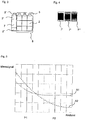
- FIG. 4 different types of Grauverlaufsfilter 7 ', 7 ", 7''' are displayed, a gradient filter 7 ', a stripe pattern (filter 7") and a jaggle pattern (filter 7''').
- a grid with points with variable distances is also possible.
- the effect of the gray gradient filter 7 is in Fig. 5 represented, with a measurement signal above the distance "sensor object" is exemplified.
- the distance signal is in each case once without Grauverlaufsfilter 7 (dotted curve S1) and once marked with Grauverlaufsfilter 7 (dashed curve S2).
Description
Die Erfindung betrifft eine Farberfassungsanordnung zum Bestimmen zumindest einer Farbe eines Objekts und ein Korrekturverfahren zur Korrektur einer erfassten Helligkeit des Objekts unter Verwendung der Farberfassungsanordnung.The invention relates to a color detection device for determining at least one color of an object and a correction method for correcting a detected brightness of the object using the color detection device.
Aus dem Stand der Technik sind Farbmesseinrichtungen bekannt, mit denen Farben bspw. von produzierten Gütern getestet werden können. Die Sensorik dieser Messeinrichtungen bestimmen u. a. die Farbanteile des empfangenen Lichtes. Um eine Farbe zu erkennen bzw. sie wieder zu erkennen, muss neben den Farbanteilen (RGB) auch die Helligkeit bestimmt werden. Die gemessene Helligkeit ist dabei abhängig vom Abstand des farbigen Objekts zum Sensor, womit für verschiedene Abstände unterschiedliche Helligkeiten gemessen werden können. So kann sich bspw. ein Braunfarbton nur durch die Helligkeit, nicht aber durch die Farbanteile von Gelbtönen unterscheiden.Color measuring devices are known from the prior art with which colors can be tested, for example, of produced goods. The sensors of these measuring devices determine u. a. the color components of the received light. In order to recognize or recognize a color, the brightness must be determined in addition to the color components (RGB). The measured brightness is dependent on the distance of the colored object to the sensor, whereby different brightnesses can be measured for different distances. For example, a brown hue can only differ in terms of brightness, but not by the color components of yellow shades.
Da die gemessene Helligkeit aber stark vom Abstand des Objektes abhängt, ist die Wiedererkennung nur in einem kleinen Abstandsbereich möglich. In einem größeren Abstandsbereich ist die Erfassung somit zu ungenau. Zusätzlich zu dem Farberkennungssensor könnte eine spezielle Abstandsmesseinrichtung verwendet werden, um die gemessene Helligkeit mit der bekannten Abhängigkeit vom Abstand zu korrigieren. Dieses Verfahren ist allerdings aufwändig und die benötigten Farbmesseinrichtungen sind teuer.Since the measured brightness depends strongly on the distance of the object, the recognition is only possible in a small distance range. In a larger distance range, the detection is therefore too inaccurate. In addition to the color detection sensor, a dedicated distance measuring device could be used to correct the measured brightness with the known distance dependence. However, this method is expensive and the required color measuring devices are expensive.
Farbsensoren mit trichterförmigen Lichtleitelementen sind bekannt aus der
Ausgehend vom Stand der Technik ist es Aufgabe der vorliegenden Erfindung, eine verbesserte Farberfassungsanordnung zum Bestimmen einer Farbe eines Objekts bereitzustellen, die einfach aufgebaut und kostengünstig ist.Starting from the prior art, it is an object of the present invention to provide an improved color detection arrangement for determining a color of an object that is simple in construction and inexpensive.
Diese Aufgabe wird durch eine Farberfassungsanordnung mit den Merkmalen des Anspruchs 1 gelöst.This object is achieved by a color detection arrangement having the features of claim 1.
Die weitere Aufgabe, die Helligkeit und damit die Farbe eines Objekts unabhängig eines Abstandsbereichs zu erkennen und die Farberkennung durch eine Farberfassungsanordnung zu verbessern, wird durch das Korrekturverfahren mit den Merkmalen des unabhängigen Anspruchs 8 gelöst.The further object, the brightness and thus the color of an object to detect independent of a distance range and to improve the color detection by a color detection device, is achieved by the correction method having the features of
Weiterbildungen der Farberfassungsanordnung und des Korrekturverfahrens sind in den jeweiligen Unteransprüchen ausgeführt.Further developments of the color detection arrangement and the correction method are embodied in the respective subclaims.
Eine erfindungsgemäße Farberfassungsanordnung dient zum Bestimmen einer oder mehrerer Farben eines Objekts. Die Anordnung weist dazu auf:- eine gerichtete Lichtquelle, die auf das zu erkennende Objekt gerichtet ist,- eine Auswerteelektronik, und- eine Farberfassungseinrichtung mit drei oder mehr Farberkennungssensoren zur Aufnahme von Strahlung, die von dem Objekt reflektiert wird. Erfindungsgemäß ist jedem Farbsensor ein Trichter als lichtleitendes Element vorgeordnet. Ferner werden zumindest zwei der Farberkennungssensoren als Abstandssensor verwendet.A color detection arrangement according to the invention serves to determine one or more colors of an object. The arrangement comprises: a directional light source which is directed at the object to be detected, an evaluation electronics, and a color detection device with three or more color recognition sensors for receiving radiation which is reflected by the object. According to the invention, each color sensor is preceded by a funnel as a light-conducting element. Further, at least two of the color detection sensors are used as the distance sensor.
Mittels dieser Anordnung kann der Abstand über zwei Trichter einer bereits vorhandenen 4x3 Trichtermatrix bestimmt werden, wobei das Abstandsignal zur Kompensation des Helligkeitssignals (Empfangsenergie pro Farbkanal) verwendet werden kann. Zur Normierung kann bspw. die empfangene Gesamtenergie zum Einsatz kommen.By means of this arrangement, the distance can be determined via two funnels of an existing 4x3 funnel matrix, wherein the distance signal can be used to compensate the brightness signal (received energy per color channel). For normalization, for example, the received total energy can be used.
Die Farberkennungssensoren bilden mit den Trichtern eine Einheit und sind in einer möglichen Ausführungsform als Sensor-Matrix mit
vier Spalten und drei Reihen angeordnet. Erfindungsgemäß werden zwei der Farberkennungssensoren als Abstandssensoren verwendet. Dazu ist eine Spalte der Sensor-Matrix für die Abstandmessung vorgesehen, in einer Ausführungsform der Farberfassungseinrichtung ist es bspw. die erste Spalte. Ferner liegen ein oberer, erster Trichter und ein unterer, zweiter Trichter in der Spalte vor. Die von diesen beiden Trichtern aufgenommenen und von dem Objekt reflektierten Lichtstrahlen werden auf die als Abstandssensoren genutzten Farberkennungssensoren geleitet. Dabei haben die Intensitäten der von den beiden Trichtern aufgenommenen Lichtstrahlen, aufgrund der unterschiedlichen Anordnung, eine unterschiedliche Abhängigkeit vom Abstand des Objektes. Der unterschiedliche Abstand zu dem Objekt, dem Sender, ist hierbei imminent, die Spaltenlage der Trichter ist dabei beliebig und nicht fest. In einer Ausführungsform kann bei einer dreireihigen Spalte der obere Trichter und der untere Trichter verwendet werden - der mittlere der drei Trichter wird nicht verwendet, bzw. hat keinen zugeordneten Sensor.The color detection sensors form a unit with the funnels and are in one possible embodiment as a sensor matrix with
arranged four columns and three rows. According to the invention, two of the color detection sensors are used as distance sensors. For this purpose, a column of the sensor matrix is provided for the distance measurement, in one embodiment of the color detection device it is, for example, the first column. Further, there are an upper, first funnel and a lower, second funnel in the column. The light rays received by these two funnels and reflected by the object are directed to the color detection sensors used as distance sensors. In this case, the intensities of the light beams received by the two funnels, due to the different arrangement, a different dependence on the distance of the object. The different distance to the object, the transmitter, is here imminent, the column position of the funnels is arbitrary and not fixed. In one embodiment, in a three row column, the top hopper and the bottom hopper may be used - the middle one of the three hopper is not used or has no associated sensor.
Die Erfindung kann vorsehen, dass jeder Trichter pyramidenstumpfförmig ist, wobei die Austrittsfläche einer Deckfläche und eine Eintrittsfläche des Trichters einer Grundfläche des Pyramidenstumpfes entsprechen. Der Pyramidenstumpf weist bevorzugt eine quadratische Grundfläche auf. Alternativ kann die Grundfläche auch dreieckig oder vieleckig mit mehr als vier Ecken sein. Diese geometrischen Formen erzeugen eine Lichtkonzentration und haben keine Linsenwirkung. Bei nicht-segmentierten Empfängern kann in bestimmten Einzelanordnungen auch eine Kegelform als Grundform Verwendung finden, wobei Grund- und Deckfläche jeweils kreisförmig sind. Zur Erläuterung der Funktionsweise der Trichter wird auf die
Vorteilhaft kann jeder Trichter als lichtleitendes Element linsenfrei sein, so dass die in jeden Trichter einfallende Strahlung bzw. das Licht maximal n-mal mit n ≤ 2 reflektiert wird. Jeder Trichter dient dabei als nichtabbildender Konzentrator vor jedem Farberkennungssensor.Advantageously, each funnel can be lens-free as a light-guiding element, so that the radiation or the light incident in each funnel is reflected a maximum of n times with n ≦ 2. Each funnel serves as a non-imaging concentrator before each color detection sensor.
Auch kann vorgesehen sein, dass die Trichter aus einem lichtdurchlässigen Vollmaterial, bevorzugt aus Glas oder synthetischem Quarzglas, bestehen. Alternativ kann ein Kunststoff, wie Acrylglas (Polymethylmethacrylat), aber auch Polycarbonat verwendet werden. Ebenfalls kommen andere transparente Kunststoffe wie Polyetherimid oder Polysulfon in Frage. Ein einzelner Trichter ist dabei bedingt durch das geringe Volumen einfach und kostengünstig herzustellen, z. B. im Spritzgussverfahren.It can also be provided that the funnels consist of a light-transmitting solid material, preferably of glass or synthetic quartz glass. Alternatively, a plastic, such as acrylic glass (polymethyl methacrylate), but also polycarbonate can be used. Also, other transparent plastics such as polyetherimide or polysulfone in question. A single funnel is due to the low volume easy and inexpensive to produce, for. B. by injection molding.
Die Erfindung kann vorsehen, dass jeder Farberkennungssensor eine oder mehrere monochrome Farbaufnahmeflächen aufweist, wobei die Farbaufnahmefläche RGB-sensitiv sein kann, d. h. insbesondere rot-, grün- oder blausensitiv. Alternativ können die Farbaufnahmeflächen auch CMY-sensitiv, insbesondere cyan-, magenta-, gelbsensitiv sein. So können in der Farberfassungseinrichtung verschiedene Farbstandards verwendet werden. Dabei können die Farbaufnahmeflächen des Farberkennungssensors in einer Ausführungsform der Erfindung Fotodioden sein, denen ein Farbfilter vorgeordnet ist. Auch können andere Sensortypen in der erfindungsgemäßen Erfindung Verwendung finden, die einzelne, monochrome Farbaufnahmeflächen realisieren. Die Farberkennung kann auch mittels dreier befilterter Fotodioden erfolgen. Es können auch mehr als drei Fotodioden verwendet werden, um bessere und mehr Signale zu erhalten, wobei auch eine Art gedoppelt werden kann.The invention can provide that each color detection sensor has one or more monochrome color-receiving surfaces, wherein the color-receiving surface can be RGB-sensitive, ie in particular red, green or blue sensitive. Alternatively, the ink receptive surfaces may also be CMY-sensitive, especially cyan, magenta, yellow-sensitive. Thus, different color standards can be used in the color detection device. In this case, the color receiving surfaces of the color detection sensor in one embodiment of the invention may be photodiodes, which is preceded by a color filter. Other sensor types can also be used in the invention according to the invention, which realize individual monochrome ink-receiving surfaces. The color recognition can also be done by means of three filtered photodiodes. There may also be more than three photodiodes can be used to get better and more signals, whereby one way can be doubled.
Zur Optimierung der Abstandskennlinie, bzw. zur Erhöhung der unterschiedlichen Intensitätsabhängigkeit vom Abstand kann ein Grauverlaufsfilter verwendet werden, der die abstandsspezifische unterschiedliche Abschattung der Nah- und Fernbereichsmessdioden verstärkt. Den zur Abstandsmessung vorgesehenen Farberkennungssensoren kann hierzu in einer Ausführungsform der Farberfassungsanordnung der Grauverlaufsfilter sein. Der Grauverlaufsfilter kann dabei so angeordnet sein, dass er einen unteren Abschnitt (bspw. ein unteres Drittel) des oberen, ersten Farbrichters und gleichzeitig einen oberen Abschnitt (bspw. ein oberes Drittel) des zweiten, unteren Farbrichters abdeckt. In einer weiteren Ausführungsform der Erfindung kann der Grauverlaufsfilter unterschiedliche Formen haben, so zum Beispiel einen Verlaufsgradienten, ein Streifenmuster, ein Zackenmuster oder auch ein Raster aus Punkten mit variablen Abständen. Weitere Möglichkeiten wären beispielsweise Verlaufsfilter mit einer variablen Transmission oder die Verwendung eines Aufdruckes mit geeigneten Geometrien zur partiellen Abschattung der Nah- bzw. Fernbereichssensoren. In einer Ausführungsform ist der Grauverlaufsfilter an der Lichteintrittsfläche, also vor dem Trichter angeordnet.To optimize the distance characteristic, or to increase the different intensity dependence of the distance, a gray gradient filter can be used, which amplifies the distance-specific different shading of the near and far range measuring diodes. For this purpose, the color detection sensor provided for measuring the distance can be the gray-color filter in one embodiment of the color detection arrangement. The gray gradient filter can be arranged in such a way that it covers a lower section (for example a lower third) of the upper, first color reflector and at the same time an upper section (for example an upper third) of the second, lower color reflector. In a further embodiment of the invention, the gray-gradient filter can have different shapes, for example a gradient gradient, a striped pattern, a serrated pattern or else a grid of dots with variable distances. Other options would be, for example, gradient filters with a variable transmission or the use of an imprint with suitable geometries for partial shading of the near or far range sensors. In one embodiment, the gray gradient filter is arranged on the light entry surface, ie in front of the funnel.
Die Farberfassungsanordnung kann so gestaltet werden, dass sie flexibel an die jeweiligen Anforderungen angepasst werden kann. So können neben farbsensitiven Photodioden als Farberkennungssensoren auch herkömmliche Fotoempfänger verwendet werden und mit einem Farbfilter versehen sein. Alle Trichter konzentrieren das Licht auf die gleiche Weise auf die Farbaufnahmefläche und ermöglichen das gleiche Abschattungsverhalten für alle Farbaufnahmeflächen. Das Rauschverhalten dieser einzelnen Farbsensoren ist aufgrund der kleineren Empfangsfläche kleiner oder gleich dem Rauschverhalten einer Farberfassungseinrichtung gesamt.The color detection arrangement can be designed so that it can be flexibly adapted to the respective requirements. Thus, in addition to color-sensitive photodiodes as color detection sensors and conventional photoreceptor can be used and provided with a color filter. All funnels concentrate the light in the same way on the ink-receiving surface and allow the same shading behavior for all ink-receptive surfaces. The noise behavior of these individual color sensors is less than or equal to the noise behavior of a color detection device due to the smaller receiving surface.
Um Farben von Objekten oder farbcharakteristische Eigenschaften oder Parameter exakt aufnehmen zu können, kann die Erfindung vorsehen, dass die Lichtquelle weißes Licht emittiert. Dabei kann die Lichtquelle eine Laseranordnung aus je einem blauen, roten und grünen Laser oder auch eine LED, LED-Anordnung oder eine andere gerichtete Lichtquelle sein.In order to accurately capture colors of objects or color characteristic properties or parameters, the invention may provide that the light source emit white light. In this case, the light source can be a laser arrangement of one blue, one red and one green laser or else an LED, LED arrangement or another directed light source.
Bei einem Korrekturverfahren zur Korrektur einer erfassten Helligkeit des Objekts wird eine erfindungsgemäße Farberfassungsanordnung verwendet. Das Verfahrens wird folgendermaßen durchgeführt:
- das Objekt wird mit Lichtstrahlen aus der Lichtquelle bestrahlt, wobei die Lichtstrahlen in Bezug zur Lichtquelle auf eine oder mehrere Position(en) des Objekts auftreffen; dabei kann das Objekt verschiedene Abstände zur Farberfassungsanordnung haben;
- die Helligkeit an der Position des Objekts wird bestimmt, indem die Intensität der von dem Objekt reflektierten Lichtstrahlen mit den Farberkennungssensoren erfasst wird und die Informationen der drei Farbanteile und der beiden zur Abstandmessung dienenden Empfängerintensitäten A1, A2 an die Auswerteelektronik übermittelt wird;
- das Differenzsignal ΔA der Signale A1 und A2 wird gebildet und mit der Gesamtempfangsenergie der Abstandssensoren mittels der Auswerteelektronik normiert und ein Korrekturfaktor für die Helligkeit bestimmt;
- und schließlich die Helligkeit durch den Korrekturfaktor aus dem normierten Differenzsignal bestimmt wird.
- the object is irradiated with light rays from the light source, the light rays incident on one or more positions of the object relative to the light source; while the object may have different distances to the color detection arrangement;
- the brightness at the position of the object is determined by detecting the intensity of the light rays reflected from the object with the color detection sensors and transmitting the information of the three color components and the two receiver measurement intensities A1, A2 serving for distance measurement to the evaluation electronics;
- the difference signal ΔA of the signals A1 and A2 is formed and normalized with the total received energy of the distance sensors by means of the evaluation and determines a correction factor for the brightness;
- and finally the brightness is determined by the correction factor from the normalized difference signal.
Unter dem Begriff eines Abstandssignals wird das Signal verstanden, das mittels der Farberkennungssensoren gemessen wird, die für die Abstandsmessung verwendet werden. Die Farberfassungseinrichtung weist bspw. als Empfangseinheit eine 4x3 Matrix aus Farberkennungssensoren bzw. Farbempfängern mit ebenso vielen vorgeordneten Trichtern auf. Eine 3x3 Untermatrix wird dabei mit neun Farbempfängern ausgestattet (3xR, 3xG, 3xB). In der verbleibenden 1x3 Matrix können nun die Trichter am Rand (nah am Sender und fern vom Sender) benutzt werden, um das abstandsabhängige Differenzsignal zu erzeugen. Nah und fern bedeutet dabei der seitliche Abstand an der Austrittsfläche der Sensoranordnung - durch diesen unterschiedlichen Abstand erhält man eine unterschiedliche Abstandsabhängigkeit der gemessenen Intensität. Vorteilhaft werden Farberkennungssensoren dazu verwendet, den Abstand zum Objekt zu bestimmen und dieser Messwert für die Korrektur der empfangenen Helligkeit benutzt. Im Prinzip wird der Abstand aus dem Differenzsignal zweier Photodioden ermittelt: ![]()
![]()
Dadurch, dass unterschiedliche Abstände zu dem zu vermessenden Objekt aufgrund unterschiedlicher Positionen auf dem Objekt selbst vorliegen, haben die beiden Trichter ein unterschiedliches Sichtfeld, somit ändert sich die empfangene Lichtintensität bei Änderung des Abstandes, analog zur Abstandsmessung per Triangulation. Da sich die Differenz der beiden Signale linear mit der Objekthelligkeit ändert, muss das Differenzsignal mit der Gesamtempfangsenergie der Abstandssensoren normiert werden: ![]()
![]()
Dieses Funktionsprinzip entspricht der bekannten Triangulations-Abstandsmessung mittels Differenzdiode.This functional principle corresponds to the known triangulation distance measurement by means of differential diode.
Um den Korrekturwert einfach zu bestimmen, kann das erfindungsgemäße Verfahren vorsehen, dass das normierte Differenzsignal mit einem Datensatz oder mehreren vorbestimmten Datensätzen verglichen wird. Daraus kann dann der Korrekturfaktor ermittelt werden, wobei aus dem Signal die Empfangsenergie pro Farbkanal ermittelt und mit vorbestimmten Datensätzen verglichen wird, wie bspw. einer geeigneten Look-Up-Tabelle.To easily determine the correction value, the inventive method can provide that the normalized difference signal is compared with one or more predetermined data sets. From this, the correction factor can then be determined, the received energy per color channel being determined from the signal and compared with predetermined data records, such as, for example, a suitable look-up table.
Dies hat insbesondere den Vorteil, dass die Helligkeit des Objektes oder eines bestimmten Punktes auf dem Objekt über einen großen Abstandsbereich bestimmt werden kann. Dadurch lässt sich sehr einfach und effektiv eine Farbe eines Objekts erfassen und korrekt bestimmen.This has the particular advantage that the brightness of the object or a specific point on the object can be determined over a large distance range. This makes it very easy and effective to capture a color of an object and determine it correctly.
Eine weitere Ausführungsform der Anordnung kann vorsehen, dass das Differenzsignal analog erzeugt wird und mittels eines A/D-Wandlers das analoge Signal in ein digitales Signal gewandelt wird. Alternativ kann vorgesehen sein, dass mittels der Abstandssensoren analoge Signale erfasst werden und mittels des A/D-Wandlers die analogen Signale in digitale Signale gewandelt werden. Eine zugehörige Datenverarbeitungseinheit, wie ein Microcontroller o. ä. kann der Anordnung zugeordnet sein, Teil von ihr sein oder an sie angeschlossen werden. Eine schnelle und einfache Datenauswertung der digitalisierten Signale kann damit vorgenommen werden.A further embodiment of the arrangement can provide that the difference signal is generated analogously and the analog signal is converted into a digital signal by means of an A / D converter. Alternatively, it can be provided that analog signals are detected by means of the distance sensors and the analog signals are converted into digital signals by means of the A / D converter. An associated data processing unit, such as a microcontroller or the like, may be associated with, part of, or connected to the device. A quick and easy data analysis of the digitized signals can be made.
Weitere Ausführungsformen der Anordnung und des Verfahrens sowie einige der Vorteile, die mit diesen und weiteren Ausführungsformen verbunden sind, werden durch die nachfolgende ausführliche Beschreibung unter Bezug auf die begleitenden Figuren deutlich und besser verständlich. Die Figuren sind lediglich eine schematische Darstellung einer Ausführungsform der Erfindung.Other embodiments of the arrangement and method, as well as some of the advantages associated with these and other embodiments, will become apparent and better understood by the following detailed description with reference to the accompanying drawings. The figures are merely a schematic representation of an embodiment of the invention.
Dabei zeigen:
- Fig. 1
- eine schematische Ansicht der Farberfassungsanordnung,
- Fig. 2
- eine schematische Perspektivansicht der Farberfassungseinrichtung mit Grauverlaufsfilter,
- Fig. 3
- eine schematische Vorderansicht der Farberfassungseinrichtung mit Grauverlaufsfilter,
- Fig. 4
- schematische Ansichten verschiedener Grauverlaufsfilter, und
- Fig. 5
- ein schematisches Diagramm gemessener Signale aufgetragen über dem Abstand Sensor-Objekt.
- Fig. 1
- a schematic view of the color detection arrangement,
- Fig. 2
- a schematic perspective view of the color detection device with Grauverlaufsfilter,
- Fig. 3
- a schematic front view of the color detection device with Grauverlaufsfilter,
- Fig. 4
- schematic views of various Grauverlaufsfilter, and
- Fig. 5
- a schematic diagram of measured signals plotted over the distance sensor object.
In
Die Farberfassungseinrichtung 10 weist eine Vielzahl an Sensoren 3 auf, denen im Lichtgang lichtleitende Elemente in Form von Trichtern 2 angeordnet sind. Durch die Trichter 2 werden die reflektierten Lichtstrahlen L' gezielt auf die Sensorfläche der Farberkennungssensoren 3 gelenkt. Die Farberkennungssensoren 3 sind in einer 4x3-Matrix angeordnet, wobei nicht alle Spalten der Matrix für die Farberkennung genutzt werden. Die linke Spalte der Matrix (in
Den Farberkennungssensoren 3 und den Abstandssensoren 3', 3" ist eine auswärtige Elektronik 5 nachgeordnet. Diese ist Bestandteil der Farberfassungseinrichtung 10 nach
Um die Abstandskennlinie, die nach
In
Die Auswirkung des Grauverlaufsfilters 7 ist in
- 11
- FarberfassungsanordnungColor detection arrangement
- 22
- Trichterfunnel
- 2', 2"2 ', 2 "
- Trichter AbstandssensorenFunnel distance sensors
- 33
- FarberkennungssensorenColor detection sensors
- 3', 3"3 ', 3 "
- Abstandssensorendistance sensors
- 44
- Lichtquellelight source
- 55
- Auswerteelektronikevaluation
- 66
- Elektrische LeitungsverbindungElectrical connection
- 77
- GrauverlaufsfilterGrauverlauffilter
- 88th
- Sensormatrixsensor matrix
- 1010
- FarberfassungseinrichtungColor detector
- LL
- Lichtstrahlenlight rays
- L'L '
- Reflektierte LichtstrahlenReflected light rays
- OO
- Objektobject
- S1S1
- Abstandssignal ohne FilterDistance signal without filter
- S2S2
- Abstandssignal mit FilterDistance signal with filter
Claims (9)
- A colour recognition arrangement (1) for determining at least one colour of an object (O), wherein the arrangement (1) comprises:- a directional light source (4) which is directed to the object (O) to be detected,- an evaluation electronics (5), and- a colour recognition device (10) having at least three colour detection sensors (3) for absorbing radiation reflected by the object (O),wherein
a funnel (2), being provided as a light conducting element, is arranged upstream of each colour detection sensor (3),
characterised in that
the colour detection sensors (3) and the funnels (2) form a sensor matrix having four columns and three rows, wherein two of the colour detection sensors (3) are used as distance sensors (3', 3"), and
wherein one column of the sensor matrix is set up for distance measurement, wherein an upper funnel (2') and a lower funnel (2") are present in the column and the rays of light (L') reflected by the object (O) and absorbed by the two funnels (2', 2") are conducted to the distance sensors (3', 3"). - The arrangement (1) according to claim 1,
characterised in that
the funnel (2) has the shape of an inverted truncated pyramid and has one light entrance surface and one opposite light exit surface, wherein the light entrance surface is larger than the light exit surface. - The arrangement (1) according to claim 1 or 2,
characterised in that
the funnels (2), being provided as light conducting elements, do not have any lenses. - The arrangement (1) according to at least any one of claims 1 to 3,
characterised in that
the colour recognition device (10) has at least one graduated neutral density filter (7) which is arranged upstream of the colour detection sensors (3', 3") that are provided for distance measurement. - The arrangement according to claim 4,
characterised in that
therein, the graduated neutral density filter (7) is arranged such that it covers a lower section of an upper first funnel (2') as well as an upper section of a second lower funnel (2'). - The arrangement (1) according to at least any one of claims 1 to 5,
characterised in that
each colour detection sensor has at least two variably monochrome colour absorption surfaces, wherein the colour absorption surface- is sensitive to RGB, more particularly sensitive to red, green or blue, or- is sensitive to CMY, more particularly sensitive to cyan, magenta or yellow. - A correction method for correcting a recognised brightness of an object (1), using a colour recognition arrangement (1) according to at least any one of claims 1 to 6,
comprising the steps of- irradiating the object with rays of light (L) from the light source (4), wherein the rays of light (L) impinge on a position (P1, P2) of the object (O), the position (P1, P2) being at least one with regard to the light source (4),- determining the brightness at the position (P1, P2) by recognising the intensities A1 and A2 of the rays of light (L') reflected from the position (P1, P2) of the object (O), using the colour detection sensors serving as distance sensors (3', 3") and transmitting the intensity information A1 and A2 to the evaluation electronics (5),- forming the differential signal of the signals A1 and A2 and scaling with the total receiving energy of the distance sensors (3', 3") using the evaluation electronics and determining a correction factor for the brightness,- correcting the determined brightness from the scaled differential signal using the correction factor. - The method according to claim 7,
comprising the step of
comparing the scaled differential signal with at least one data record and determining the correction factor therefrom, therein determining from the signal the receiving energy per colour channel and comparing with predetermined data records. - The method according to claim 7 or 8,
comprising the steps of- generating the analogue differential signal as well as the analogue sum signal and- converting the analogue signals into digital signals by means of an analogue digital converter, and- determining the scaled differential signal from the digitised signals in the evaluation electronics (5),
or- recognising analogue signals by means of the distance sensors (3', 3"),- converting the analogue signals into digital signals by means of the analogue digital converter, and- determining the scaled differential signal from the digitised signals in the evaluation electronics (5).
Applications Claiming Priority (1)
| Application Number | Priority Date | Filing Date | Title |
|---|---|---|---|
| DE102017003703.5A DE102017003703B4 (en) | 2017-04-18 | 2017-04-18 | Color detection arrangement and correction method using the color detection device |
Publications (2)
| Publication Number | Publication Date |
|---|---|
| EP3407039A1 EP3407039A1 (en) | 2018-11-28 |
| EP3407039B1 true EP3407039B1 (en) | 2019-10-16 |
Family
ID=61131882
Family Applications (1)
| Application Number | Title | Priority Date | Filing Date |
|---|---|---|---|
| EP18000050.7A Active EP3407039B1 (en) | 2017-04-18 | 2018-01-23 | Colour detecting arrangement and correction method using the colour detecting arrangement |
Country Status (3)
| Country | Link |
|---|---|
| US (1) | US10429239B2 (en) |
| EP (1) | EP3407039B1 (en) |
| DE (1) | DE102017003703B4 (en) |
Families Citing this family (1)
| Publication number | Priority date | Publication date | Assignee | Title |
|---|---|---|---|---|
| DE102018105607B4 (en) * | 2018-03-12 | 2022-05-25 | Sick Ag | Photoelectric sensor and method for detecting objects in a surveillance area |
Family Cites Families (9)
| Publication number | Priority date | Publication date | Assignee | Title |
|---|---|---|---|---|
| JPH09288007A (en) * | 1996-04-22 | 1997-11-04 | Minolta Co Ltd | Spectral colorimeter |
| DE10016349B4 (en) | 2000-04-03 | 2007-09-27 | Sensopart Industriesensorik Gmbh | Method and arrangement for detecting and / or detecting an object |
| DE10242374A1 (en) * | 2002-09-12 | 2004-04-01 | Siemens Ag | Confocal distance sensor |
| DE10317447A1 (en) * | 2003-04-16 | 2004-11-18 | Nexpress Solutions Llc | Method and sensor device for detecting colors |
| US20120004884A1 (en) * | 2008-01-23 | 2012-01-05 | Bernard Fillol | Device and method for the space-colorimetric measurement of a three-dimensional object |
| DE202009018897U1 (en) * | 2008-09-02 | 2014-04-14 | Breitmeier Messtechnik Gmbh | Roughness and / or profile measuring device |
| US8542311B2 (en) * | 2011-01-20 | 2013-09-24 | Aptina Imaging Corporation | Multisection light guides for image sensor pixels |
| US9231013B2 (en) * | 2011-11-08 | 2016-01-05 | Semiconductor Components Industries, Llc | Resonance enhanced absorptive color filters having resonance cavities |
| DE102012107046B4 (en) * | 2012-08-01 | 2020-01-02 | Deutsches Zentrum für Luft- und Raumfahrt e.V. | imaging device |
-
2017
- 2017-04-18 DE DE102017003703.5A patent/DE102017003703B4/en not_active Expired - Fee Related
-
2018
- 2018-01-23 EP EP18000050.7A patent/EP3407039B1/en active Active
- 2018-03-14 US US15/921,405 patent/US10429239B2/en active Active
Non-Patent Citations (1)
| Title |
|---|
| None * |
Also Published As
| Publication number | Publication date |
|---|---|
| DE102017003703B4 (en) | 2018-12-13 |
| DE102017003703A1 (en) | 2018-10-18 |
| US10429239B2 (en) | 2019-10-01 |
| EP3407039A1 (en) | 2018-11-28 |
| US20180299325A1 (en) | 2018-10-18 |
Similar Documents
| Publication | Publication Date | Title |
|---|---|---|
| EP2270451B1 (en) | Colour measuring device | |
| DE19721105C2 (en) | Optoelectronic sensor | |
| EP1610270A2 (en) | Process for qualitative evaluation of a material with at least one identification characteristic | |
| DE102012016675A1 (en) | Method for color calibration of a color monitor with LED backlight | |
| WO2016087609A1 (en) | Pulse oximetry device and method for operating a pulse oximetry device | |
| DE102014116081A1 (en) | Beverage preparation device for portion units and operating method | |
| EP0852709A1 (en) | Multispectral sensor device | |
| EP3407039B1 (en) | Colour detecting arrangement and correction method using the colour detecting arrangement | |
| DE102011114410A1 (en) | A method of checking the manufacturing quality of an optical security feature of a value document | |
| EP1642098B1 (en) | Method and system for the metrological detection of differences in the visually perceived color impression between a multicolored patterned surface of a reference and a multicolored patterned surface of a specimen | |
| DE102014218460B4 (en) | Assistance system of a motor vehicle, with a camera and image sensor | |
| DE102006015269A1 (en) | Spectrometric measuring system and method for compensation of stray light | |
| DE102009046740B3 (en) | Apparatus and method for locating modulated optical radiation sources | |
| DE112021005281T5 (en) | MULTISPECTRAL OPTICAL SENSOR AND SYSTEM | |
| DE102021202427A1 (en) | Detector device and sensor unit | |
| DE3633199C2 (en) | ||
| DE2217281A1 (en) | Density measurement through image analysis. > | |
| EP2656329B1 (en) | Method for generating a digital image of at least one section of a value document | |
| DE102016208409A1 (en) | Sensor module, method for determining a brightness and / or a color of electromagnetic radiation and method for producing a sensor module | |
| EP3220112B1 (en) | Device with at least one optical sensor module and operating method for same | |
| DE102021201074A1 (en) | Detector assembly and optical sensor | |
| EP3887798A1 (en) | Spectrometer apparatus and a corresponding method for operating a spectrometer apparatus | |
| DE102009047437A1 (en) | Method and device for adapting image information of an optical system | |
| EP2017653B1 (en) | Optoelectronic sensor and reception method with correction of light interference or stray light | |
| DE102020125235A1 (en) | camera and spectrophotometer |
Legal Events
| Date | Code | Title | Description |
|---|---|---|---|
| PUAI | Public reference made under article 153(3) epc to a published international application that has entered the european phase |
Free format text: ORIGINAL CODE: 0009012 |
|
| STAA | Information on the status of an ep patent application or granted ep patent |
Free format text: STATUS: THE APPLICATION HAS BEEN PUBLISHED |
|
| AK | Designated contracting states |
Kind code of ref document: A1 Designated state(s): AL AT BE BG CH CY CZ DE DK EE ES FI FR GB GR HR HU IE IS IT LI LT LU LV MC MK MT NL NO PL PT RO RS SE SI SK SM TR |
|
| AX | Request for extension of the european patent |
Extension state: BA ME |
|
| STAA | Information on the status of an ep patent application or granted ep patent |
Free format text: STATUS: REQUEST FOR EXAMINATION WAS MADE |
|
| 17P | Request for examination filed |
Effective date: 20190118 |
|
| RBV | Designated contracting states (corrected) |
Designated state(s): AL AT BE BG CH CY CZ DE DK EE ES FI FR GB GR HR HU IE IS IT LI LT LU LV MC MK MT NL NO PL PT RO RS SE SI SK SM TR |
|
| GRAP | Despatch of communication of intention to grant a patent |
Free format text: ORIGINAL CODE: EPIDOSNIGR1 |
|
| STAA | Information on the status of an ep patent application or granted ep patent |
Free format text: STATUS: GRANT OF PATENT IS INTENDED |
|
| INTG | Intention to grant announced |
Effective date: 20190425 |
|
| GRAS | Grant fee paid |
Free format text: ORIGINAL CODE: EPIDOSNIGR3 |
|
| GRAA | (expected) grant |
Free format text: ORIGINAL CODE: 0009210 |
|
| STAA | Information on the status of an ep patent application or granted ep patent |
Free format text: STATUS: THE PATENT HAS BEEN GRANTED |
|
| AK | Designated contracting states |
Kind code of ref document: B1 Designated state(s): AL AT BE BG CH CY CZ DE DK EE ES FI FR GB GR HR HU IE IS IT LI LT LU LV MC MK MT NL NO PL PT RO RS SE SI SK SM TR |
|
| REG | Reference to a national code |
Ref country code: GB Ref legal event code: FG4D Free format text: NOT ENGLISH |
|
| REG | Reference to a national code |
Ref country code: DE Ref legal event code: R096 Ref document number: 502018000280 Country of ref document: DE Ref country code: CH Ref legal event code: EP |
|
| REG | Reference to a national code |
Ref country code: IE Ref legal event code: FG4D Free format text: LANGUAGE OF EP DOCUMENT: GERMAN |
|
| REG | Reference to a national code |
Ref country code: AT Ref legal event code: REF Ref document number: 1191731 Country of ref document: AT Kind code of ref document: T Effective date: 20191115 |
|
| REG | Reference to a national code |
Ref country code: NL Ref legal event code: MP Effective date: 20191016 |
|
| REG | Reference to a national code |
Ref country code: LT Ref legal event code: MG4D |
|
| PG25 | Lapsed in a contracting state [announced via postgrant information from national office to epo] |
Ref country code: NL Free format text: LAPSE BECAUSE OF FAILURE TO SUBMIT A TRANSLATION OF THE DESCRIPTION OR TO PAY THE FEE WITHIN THE PRESCRIBED TIME-LIMIT Effective date: 20191016 Ref country code: PT Free format text: LAPSE BECAUSE OF FAILURE TO SUBMIT A TRANSLATION OF THE DESCRIPTION OR TO PAY THE FEE WITHIN THE PRESCRIBED TIME-LIMIT Effective date: 20200217 Ref country code: LT Free format text: LAPSE BECAUSE OF FAILURE TO SUBMIT A TRANSLATION OF THE DESCRIPTION OR TO PAY THE FEE WITHIN THE PRESCRIBED TIME-LIMIT Effective date: 20191016 Ref country code: FI Free format text: LAPSE BECAUSE OF FAILURE TO SUBMIT A TRANSLATION OF THE DESCRIPTION OR TO PAY THE FEE WITHIN THE PRESCRIBED TIME-LIMIT Effective date: 20191016 Ref country code: BG Free format text: LAPSE BECAUSE OF FAILURE TO SUBMIT A TRANSLATION OF THE DESCRIPTION OR TO PAY THE FEE WITHIN THE PRESCRIBED TIME-LIMIT Effective date: 20200116 Ref country code: SE Free format text: LAPSE BECAUSE OF FAILURE TO SUBMIT A TRANSLATION OF THE DESCRIPTION OR TO PAY THE FEE WITHIN THE PRESCRIBED TIME-LIMIT Effective date: 20191016 Ref country code: LV Free format text: LAPSE BECAUSE OF FAILURE TO SUBMIT A TRANSLATION OF THE DESCRIPTION OR TO PAY THE FEE WITHIN THE PRESCRIBED TIME-LIMIT Effective date: 20191016 Ref country code: GR Free format text: LAPSE BECAUSE OF FAILURE TO SUBMIT A TRANSLATION OF THE DESCRIPTION OR TO PAY THE FEE WITHIN THE PRESCRIBED TIME-LIMIT Effective date: 20200117 Ref country code: PL Free format text: LAPSE BECAUSE OF FAILURE TO SUBMIT A TRANSLATION OF THE DESCRIPTION OR TO PAY THE FEE WITHIN THE PRESCRIBED TIME-LIMIT Effective date: 20191016 Ref country code: NO Free format text: LAPSE BECAUSE OF FAILURE TO SUBMIT A TRANSLATION OF THE DESCRIPTION OR TO PAY THE FEE WITHIN THE PRESCRIBED TIME-LIMIT Effective date: 20200116 |
|
| PG25 | Lapsed in a contracting state [announced via postgrant information from national office to epo] |
Ref country code: HR Free format text: LAPSE BECAUSE OF FAILURE TO SUBMIT A TRANSLATION OF THE DESCRIPTION OR TO PAY THE FEE WITHIN THE PRESCRIBED TIME-LIMIT Effective date: 20191016 Ref country code: RS Free format text: LAPSE BECAUSE OF FAILURE TO SUBMIT A TRANSLATION OF THE DESCRIPTION OR TO PAY THE FEE WITHIN THE PRESCRIBED TIME-LIMIT Effective date: 20191016 Ref country code: IS Free format text: LAPSE BECAUSE OF FAILURE TO SUBMIT A TRANSLATION OF THE DESCRIPTION OR TO PAY THE FEE WITHIN THE PRESCRIBED TIME-LIMIT Effective date: 20200224 |
|
| PG25 | Lapsed in a contracting state [announced via postgrant information from national office to epo] |
Ref country code: AL Free format text: LAPSE BECAUSE OF FAILURE TO SUBMIT A TRANSLATION OF THE DESCRIPTION OR TO PAY THE FEE WITHIN THE PRESCRIBED TIME-LIMIT Effective date: 20191016 |
|
| REG | Reference to a national code |
Ref country code: DE Ref legal event code: R097 Ref document number: 502018000280 Country of ref document: DE |
|
| PG2D | Information on lapse in contracting state deleted |
Ref country code: IS |
|
| PG25 | Lapsed in a contracting state [announced via postgrant information from national office to epo] |
Ref country code: RO Free format text: LAPSE BECAUSE OF FAILURE TO SUBMIT A TRANSLATION OF THE DESCRIPTION OR TO PAY THE FEE WITHIN THE PRESCRIBED TIME-LIMIT Effective date: 20191016 Ref country code: CZ Free format text: LAPSE BECAUSE OF FAILURE TO SUBMIT A TRANSLATION OF THE DESCRIPTION OR TO PAY THE FEE WITHIN THE PRESCRIBED TIME-LIMIT Effective date: 20191016 Ref country code: ES Free format text: LAPSE BECAUSE OF FAILURE TO SUBMIT A TRANSLATION OF THE DESCRIPTION OR TO PAY THE FEE WITHIN THE PRESCRIBED TIME-LIMIT Effective date: 20191016 Ref country code: EE Free format text: LAPSE BECAUSE OF FAILURE TO SUBMIT A TRANSLATION OF THE DESCRIPTION OR TO PAY THE FEE WITHIN THE PRESCRIBED TIME-LIMIT Effective date: 20191016 Ref country code: DK Free format text: LAPSE BECAUSE OF FAILURE TO SUBMIT A TRANSLATION OF THE DESCRIPTION OR TO PAY THE FEE WITHIN THE PRESCRIBED TIME-LIMIT Effective date: 20191016 Ref country code: IS Free format text: LAPSE BECAUSE OF FAILURE TO SUBMIT A TRANSLATION OF THE DESCRIPTION OR TO PAY THE FEE WITHIN THE PRESCRIBED TIME-LIMIT Effective date: 20200216 |
|
| PLBE | No opposition filed within time limit |
Free format text: ORIGINAL CODE: 0009261 |
|
| STAA | Information on the status of an ep patent application or granted ep patent |
Free format text: STATUS: NO OPPOSITION FILED WITHIN TIME LIMIT |
|
| PG25 | Lapsed in a contracting state [announced via postgrant information from national office to epo] |
Ref country code: SK Free format text: LAPSE BECAUSE OF FAILURE TO SUBMIT A TRANSLATION OF THE DESCRIPTION OR TO PAY THE FEE WITHIN THE PRESCRIBED TIME-LIMIT Effective date: 20191016 Ref country code: MC Free format text: LAPSE BECAUSE OF FAILURE TO SUBMIT A TRANSLATION OF THE DESCRIPTION OR TO PAY THE FEE WITHIN THE PRESCRIBED TIME-LIMIT Effective date: 20191016 Ref country code: SM Free format text: LAPSE BECAUSE OF FAILURE TO SUBMIT A TRANSLATION OF THE DESCRIPTION OR TO PAY THE FEE WITHIN THE PRESCRIBED TIME-LIMIT Effective date: 20191016 Ref country code: IT Free format text: LAPSE BECAUSE OF FAILURE TO SUBMIT A TRANSLATION OF THE DESCRIPTION OR TO PAY THE FEE WITHIN THE PRESCRIBED TIME-LIMIT Effective date: 20191016 |
|
| 26N | No opposition filed |
Effective date: 20200717 |
|
| REG | Reference to a national code |
Ref country code: BE Ref legal event code: MM Effective date: 20200131 |
|
| PG25 | Lapsed in a contracting state [announced via postgrant information from national office to epo] |
Ref country code: LU Free format text: LAPSE BECAUSE OF NON-PAYMENT OF DUE FEES Effective date: 20200123 |
|
| PG25 | Lapsed in a contracting state [announced via postgrant information from national office to epo] |
Ref country code: BE Free format text: LAPSE BECAUSE OF NON-PAYMENT OF DUE FEES Effective date: 20200131 Ref country code: SI Free format text: LAPSE BECAUSE OF FAILURE TO SUBMIT A TRANSLATION OF THE DESCRIPTION OR TO PAY THE FEE WITHIN THE PRESCRIBED TIME-LIMIT Effective date: 20191016 |
|
| PG25 | Lapsed in a contracting state [announced via postgrant information from national office to epo] |
Ref country code: IE Free format text: LAPSE BECAUSE OF NON-PAYMENT OF DUE FEES Effective date: 20200123 |
|
| REG | Reference to a national code |
Ref country code: CH Ref legal event code: PL |
|
| PG25 | Lapsed in a contracting state [announced via postgrant information from national office to epo] |
Ref country code: LI Free format text: LAPSE BECAUSE OF NON-PAYMENT OF DUE FEES Effective date: 20210131 Ref country code: CH Free format text: LAPSE BECAUSE OF NON-PAYMENT OF DUE FEES Effective date: 20210131 |
|
| PG25 | Lapsed in a contracting state [announced via postgrant information from national office to epo] |
Ref country code: TR Free format text: LAPSE BECAUSE OF FAILURE TO SUBMIT A TRANSLATION OF THE DESCRIPTION OR TO PAY THE FEE WITHIN THE PRESCRIBED TIME-LIMIT Effective date: 20191016 Ref country code: MT Free format text: LAPSE BECAUSE OF FAILURE TO SUBMIT A TRANSLATION OF THE DESCRIPTION OR TO PAY THE FEE WITHIN THE PRESCRIBED TIME-LIMIT Effective date: 20191016 Ref country code: CY Free format text: LAPSE BECAUSE OF FAILURE TO SUBMIT A TRANSLATION OF THE DESCRIPTION OR TO PAY THE FEE WITHIN THE PRESCRIBED TIME-LIMIT Effective date: 20191016 |
|
| PG25 | Lapsed in a contracting state [announced via postgrant information from national office to epo] |
Ref country code: MK Free format text: LAPSE BECAUSE OF FAILURE TO SUBMIT A TRANSLATION OF THE DESCRIPTION OR TO PAY THE FEE WITHIN THE PRESCRIBED TIME-LIMIT Effective date: 20191016 |
|
| PGFP | Annual fee paid to national office [announced via postgrant information from national office to epo] |
Ref country code: FR Payment date: 20230123 Year of fee payment: 6 |
|
| PGFP | Annual fee paid to national office [announced via postgrant information from national office to epo] |
Ref country code: GB Payment date: 20230124 Year of fee payment: 6 Ref country code: DE Payment date: 20230119 Year of fee payment: 6 |
|
| REG | Reference to a national code |
Ref country code: AT Ref legal event code: MM01 Ref document number: 1191731 Country of ref document: AT Kind code of ref document: T Effective date: 20230123 |