EP3406964B1 - Swinging led lamp with wireless charging function - Google Patents
Swinging led lamp with wireless charging function Download PDFInfo
- Publication number
- EP3406964B1 EP3406964B1 EP17181087.2A EP17181087A EP3406964B1 EP 3406964 B1 EP3406964 B1 EP 3406964B1 EP 17181087 A EP17181087 A EP 17181087A EP 3406964 B1 EP3406964 B1 EP 3406964B1
- Authority
- EP
- European Patent Office
- Prior art keywords
- led
- control circuit
- light
- circuit board
- led lamp
- Prior art date
- Legal status (The legal status is an assumption and is not a legal conclusion. Google has not performed a legal analysis and makes no representation as to the accuracy of the status listed.)
- Active
Links
- 239000000725 suspension Substances 0.000 claims description 30
- 229910003460 diamond Inorganic materials 0.000 claims description 5
- 239000010432 diamond Substances 0.000 claims description 5
- 239000012188 paraffin wax Substances 0.000 claims description 3
- 238000005516 engineering process Methods 0.000 description 12
- 238000010586 diagram Methods 0.000 description 6
- 230000000694 effects Effects 0.000 description 5
- 238000000034 method Methods 0.000 description 5
- 230000008859 change Effects 0.000 description 4
- 239000003086 colorant Substances 0.000 description 4
- 230000009471 action Effects 0.000 description 3
- 230000005674 electromagnetic induction Effects 0.000 description 3
- 230000006698 induction Effects 0.000 description 3
- 230000008569 process Effects 0.000 description 3
- 230000004308 accommodation Effects 0.000 description 2
- 238000006243 chemical reaction Methods 0.000 description 2
- WABPQHHGFIMREM-UHFFFAOYSA-N lead(0) Chemical compound [Pb] WABPQHHGFIMREM-UHFFFAOYSA-N 0.000 description 2
- 230000007246 mechanism Effects 0.000 description 2
- 239000011324 bead Substances 0.000 description 1
- 230000009286 beneficial effect Effects 0.000 description 1
- 239000013078 crystal Substances 0.000 description 1
- 230000005611 electricity Effects 0.000 description 1
- 239000011521 glass Substances 0.000 description 1
- 239000000463 material Substances 0.000 description 1
- 230000010355 oscillation Effects 0.000 description 1
- 239000012780 transparent material Substances 0.000 description 1
Images


Classifications
-
- F—MECHANICAL ENGINEERING; LIGHTING; HEATING; WEAPONS; BLASTING
- F21—LIGHTING
- F21V—FUNCTIONAL FEATURES OR DETAILS OF LIGHTING DEVICES OR SYSTEMS THEREOF; STRUCTURAL COMBINATIONS OF LIGHTING DEVICES WITH OTHER ARTICLES, NOT OTHERWISE PROVIDED FOR
- F21V21/00—Supporting, suspending, or attaching arrangements for lighting devices; Hand grips
- F21V21/14—Adjustable mountings
-
- F—MECHANICAL ENGINEERING; LIGHTING; HEATING; WEAPONS; BLASTING
- F21—LIGHTING
- F21L—LIGHTING DEVICES OR SYSTEMS THEREOF, BEING PORTABLE OR SPECIALLY ADAPTED FOR TRANSPORTATION
- F21L4/00—Electric lighting devices with self-contained electric batteries or cells
- F21L4/08—Electric lighting devices with self-contained electric batteries or cells characterised by means for in situ recharging of the batteries or cells
-
- F—MECHANICAL ENGINEERING; LIGHTING; HEATING; WEAPONS; BLASTING
- F21—LIGHTING
- F21S—NON-PORTABLE LIGHTING DEVICES; SYSTEMS THEREOF; VEHICLE LIGHTING DEVICES SPECIALLY ADAPTED FOR VEHICLE EXTERIORS
- F21S10/00—Lighting devices or systems producing a varying lighting effect
- F21S10/04—Lighting devices or systems producing a varying lighting effect simulating flames
- F21S10/046—Lighting devices or systems producing a varying lighting effect simulating flames by movement of parts, e.g. by movement of reflectors or light sources
-
- F—MECHANICAL ENGINEERING; LIGHTING; HEATING; WEAPONS; BLASTING
- F21—LIGHTING
- F21S—NON-PORTABLE LIGHTING DEVICES; SYSTEMS THEREOF; VEHICLE LIGHTING DEVICES SPECIALLY ADAPTED FOR VEHICLE EXTERIORS
- F21S6/00—Lighting devices intended to be free-standing
- F21S6/001—Lighting devices intended to be free-standing being candle-shaped
-
- H—ELECTRICITY
- H02—GENERATION; CONVERSION OR DISTRIBUTION OF ELECTRIC POWER
- H02J—CIRCUIT ARRANGEMENTS OR SYSTEMS FOR SUPPLYING OR DISTRIBUTING ELECTRIC POWER; SYSTEMS FOR STORING ELECTRIC ENERGY
- H02J50/00—Circuit arrangements or systems for wireless supply or distribution of electric power
- H02J50/10—Circuit arrangements or systems for wireless supply or distribution of electric power using inductive coupling
-
- H04B5/79—
-
- F—MECHANICAL ENGINEERING; LIGHTING; HEATING; WEAPONS; BLASTING
- F21—LIGHTING
- F21W—INDEXING SCHEME ASSOCIATED WITH SUBCLASSES F21K, F21L, F21S and F21V, RELATING TO USES OR APPLICATIONS OF LIGHTING DEVICES OR SYSTEMS
- F21W2121/00—Use or application of lighting devices or systems for decorative purposes, not provided for in codes F21W2102/00 – F21W2107/00
-
- F—MECHANICAL ENGINEERING; LIGHTING; HEATING; WEAPONS; BLASTING
- F21—LIGHTING
- F21Y—INDEXING SCHEME ASSOCIATED WITH SUBCLASSES F21K, F21L, F21S and F21V, RELATING TO THE FORM OR THE KIND OF THE LIGHT SOURCES OR OF THE COLOUR OF THE LIGHT EMITTED
- F21Y2115/00—Light-generating elements of semiconductor light sources
- F21Y2115/10—Light-emitting diodes [LED]
Definitions
- the present invention relates to an LED lamp, in particular to a swinging LED lamp with a wireless charging function.
- An LED bulb of an existing magnetic suspension LED lamp is suspended on a base only by using magnetic force provided by the base.
- the LED bulb is connected with a power source end in the base by a power wire to realize wired power supply, or a button hole battery is arranged in the LED bulb to realize power supply.
- the former way is a wired power supply way with the power wire, which reduces the sense of science and technology of the magnetic suspension LED lamp.
- the latter way increases the weight of the LED bulb, causing that the magnetic force on the base is hard to keep the LED bulb in a suspension state when the quantity of electricity in the internal button hole battery is decayed.
- the existing magnetic suspension LED lamp cannot realize a dynamic swinging effect, and generally adopts the white-light LED as a light source, causing single light emission and no change in light-emitting colors.
- a wireless charging technology is a novel charging technology that emerges in recent years.
- the wireless charging technology based on an electromagnetic induction principle is already mature currently.
- the technology provides a preferred solution for wireless charging of portable electronic equipment.
- CN205619160U discloses a magnetic suspension LED lamp with wireless function of charging, including a base and a suspension bulb, the base having a shell with an electro-magnet, a transmitting coil, a main control circuit board and a power end therein, the transmitting coil connected with the power end via the main control circuit board.
- the suspension bulb includes a lampshade, a receiving coil and LED lamp in the lampshade, and a permanent magnet at the bottom of the lamp shade bottom, the LED lamp pearl with the receiving coil is electrically connected.
- the permanent magnet and the electro-magnet are mutually exclusive.
- WO2012000418A1 discloses an electronic light emitting device and method for simulating a real flame.
- the electronic light emitting device includes a casing, a light emitting element, a flame sheet, and a swing mechanism.
- the flame sheet is movably suspended on the casing.
- the flame sheet comprises an upper sheet, which simulates a flame shape.
- the upper sheet is disposed outside the casing, and the light emitting element is disposed in the casing.
- the light emergence direction of the light emitting element is intersected with the upper sheet, so that the light from the light emitting element is projected on the surface of the upper sheet.
- the swing mechanism is arranged under the flame sheet in order to apply an acting force on the flame sheet, so that the flame sheet sways or swings.
- CN CN202791780 U discloses an electronic candle, which comprises a shell, a candlelight display screen, a light source, an electromagnetic coil and a control circuit board, he candlelight display screen includes a display part raised from the shell, an accommodation part for accommodating a magnet and a connecting part for connecting the display part with the accommodation part; the connecting part is in rotating connection with the shell; candlelight spots generated by the light source are mapped onto the display part; the electromagnetic coil is positioned below the magnet; and the control circuit board is electrically connected with the electromagnetic coil to control the electromagnetic coil to continuously generate a magnetic field.
- RGB mode red, green and blue
- RGB red, green and blue
- LED lamps in the prior art only have a lighting function, thereby causing a single function and lacking of the sense of science and technology and the interest.
- the existing LED lamps generally adopt a monochromatic LED as the light source, which emits single light and cannot realize flexible adjustment of the light-emitting colors.
- a swinging LED lamp with a wireless charging function comprises: a fixing portion comprising: a base and a lug boss formed at an upper end of the base, wherein a main control circuit board and a power source end are arranged in the base; an electromagnet and transmitting coil are arranged in the lug boss; the electromagnet and the transmitting coil are electrically connected with the power source end through the main control circuit board respectively; the lug boss is connected with a fixed ring perpendicular to the lug boss; and a spike is formed at a top end of the fixed ring.
- the swinging LED lamp also comprises a magnetic suspension portion comprising a pendant, a floating ring and a lamp base, wherein the pendant is connected to a bottom end of the floating ring; the lamp base is connected to a top end of the floating ring; a permanent magnet and a receiving coil are arranged in the pendant; an LED control circuit board and a LED bulb electrically connected with the LED control circuit board are arranged on an upper end surface of the lamp base; the LED control circuit board is electrically connected with the receiving coil; a groove used in combination with the spike is in a central position of a lower end surface of the lamp base; a width of the groove is greater than that of the spike; a depth of the groove is smaller than a height of the and after the spike enters the groove, the spike and the groove form point contact.
- the floating ring is sleeved on the fixed ring; the lamp base is located above the fixed ring; the pendant is located above the lug boss; and the permanent magnet and the electromagnet in a power-on state are mutual
- the first LED bulb comprises a lampshade and an LED light-emitting component arranged in the lampshade; the LED light-emitting component is electrically connected with an LED control circuit; the LED control circuit is connected with a receiving antenna; the receiving antenna is used for receiving a control signal emitted by an external control terminal; and the control circuit controls a light-emitting state of the LED light-emitting component based on the received control signal.
- the LED light-emitting component comprises a white-light LED and an RGB-light LED group; and the LED control circuit controls a lighting combination of the white-light LED and the RGB-light LED group to control the light-emitting state of the LED light-emitting component.
- a diffuse reflection part is arranged on the upper end surface of the pendant; second LED bulbs are symmetrically arranged on a left side and a right side of the fixed ring; and the second LED bulbs are electrically connected with the LED control circuit board.
- the diffuse reflection part is an artificial diamond.
- the power source end is connected with an external DC (Direct Current) power source.
- DC Direct Current
- the power source end is connected with a storage battery arranged in the base.
- the swinging LED lamp further comprises a housing for accommodating the fixing portion and the magnetic suspension portion.
- the swinging LED lamp further comprises a laser projection lamp arranged on the base and located in the housing; and the laser projection lamp is electrically connected with the main control circuit board.
- the laser projection lamp comprises a detachable housing having an opened upper end as well as a projection sheet and a laser tube arranged in the detachable housing; the laser tube is located below the projection sheet; and the laser tube is electrically connected with the main control circuit board.
- the detachable housing comprises a side wall and a bottom portion; an annular clamping groove protruding outwards is formed in the middle of the side wall; a through hole is formed in the bottom portion; the projection sheet is clamped in the clamping groove; and the laser tube is penetrated into the bottom portion through the through hole.
- the housing is a plastic housing.
- the housing is a paraffin housing.
- the present invention has the following beneficial effects: 1. a magnetic suspension technology is used to suspend a suspension induction bulb, and a wireless charging technology is adopted to supply power to the LED lamp, so that the LED lamp of the present invention has the sense of science and technology; 2. the suspension induction bulb can realize low-amplitude swinging in a balanced state, thereby generating a dynamic light-emitting effect and increasing the interest of the present invention; and 3. a lighting function and a laser projection function are integrated to help to enhance the sense of science and technology and the interest of the LED lamp.
- Fig. 1 to Fig. 6 comprise a fixing portion 1, a base 11, a lug boss 12, a fixed ring 13, a spike 14, an electromagnet 15, a transmitting coil 16, a main control circuit board 17, a power source end 18, a second LED bulb 19, a magnetic suspension portion 2, a pendant 21, a floating ring 22, a lamp base 23, a first LED bulb 24, a groove 25, a permanent magnet 26, a receiving coil 27, an artificial diamond 28, a laser projection lamp 3, a detachable housing 31, a projection sheet 311, a clamping groove 312, a laser tube 313, a through hole 314, a lead wire 32, a light-transmitting mirror 33 and a housing 4.
- a swinging LED lamp with a wireless charging function comprises a fixing portion 1 and a magnetic suspension portion 2, wherein the fixing portion 1 comprises a base 11 and a lug boss 12 formed at an upper end of the base 11.
- a main control circuit board 17 and a power source end 18 are arranged in the base 11.
- An electromagnet 15 and a transmitting coil 16 are arranged in the lug boss 12.
- the electromagnet 15 and the transmitting coil 16 are electrically connected with the power source end 18 through the main control circuit board 17, respectively.
- the lug boss 12 is connected with a fixed ring 13 perpendicular to the lug boss 12.
- a spike 14 is formed at a top end of the fixed ring 13.
- the power source end 18 is connected with a storage battery (not shown) arranged in the base 11.
- the main control circuit board 17 processes current outputted by the storage battery and then supplies the current to the electromagnet 15 and the transmitting coil 16.
- the power source end 7 can also be connected with an external DC (Direct Current) or AC (Alternate Current) power source
- a control knob (not shown) is arranged on an outer wall of the base 11.
- the control knob is connected with the main control circuit board 17.
- the control knob is used for controlling the magnitude of the current outputted by the main control circuit board 17.
- the magnetic suspension portion 2 comprises a pendant 21, a floating ring 22 and a lamp base 23.
- the pendant 21 is connected to a bottom end of the floating ring 22.
- the lamp base 23 is connected to a top end of the floating ring 22.
- a permanent magnet 26 and a receiving coil 27 are arranged in the pendant 21.
- An LED control circuit board (not shown) and a first LED bulb 24 electrically connected with the LED control circuit board are arranged on an upper end surface of the lamp base 23. The LED control circuit board is electrically connected with the receiving coil 27.
- a groove 25 used in combination with the spike 14 is formed in a central position of a lower end surface of the lamp base 23.
- a width of the groove 25 is greater than that of the spike 14.
- a depth of the groove 25 is greater than that of the spike 14. The spike 14 can enter the groove 25 and form point contact with the groove 25.
- the floating ring 22 is sleeved on the fixed ring 13.
- the lamp base 23 is located above the fixed ring 13.
- the pendant 21 is located above the lug boss 12.
- the permanent magnet 26 and the electromagnet 15 in a power-on state are mutually exclusive.
- the swinging LED lamp with the wireless charging function in the present embodiment further comprises a housing 4.
- the fixing portion 1 and the magnetic suspension portion 2 are located in the housing.
- the housing is a plastic housing.
- a paraffin housing, a glass housing and housings made of other materials can also be adopted.
- a hole matched with the lamp base is formed in the housing.
- the first LED bulb 24 comprises a lampshade (not shown) and an LED light-emitting component (not shown) arranged in the lampshade.
- the LED light-emitting component is electrically connected with the LED control circuit board.
- the LED control circuit board is connected with a receiving antenna.
- the receiving antenna is used for receiving a control signal emitted by an external control terminal (e.g., a remote controller, a mobile phone, etc.).
- the control circuit board controls a light-emitting state of the first LED bulb 24 based on the received control signal.
- the light-emitting state comprises a light color and a light intensity.
- the LED light-emitting component comprises a white-light LED and an RGB-light LED group.
- the control terminal controls the lighting of RGB single-color light LED or the mixed-color lighting of RG, GB, RB and RGB-light LEDs in a remote control way, so as to realize color change and meet needs of different lighting occasions.
- the white-light LED can be lighted only to meet normal lighting needs.
- the RGB color change of the LED light-emitting component is realized in the remote control way, which is a mature technology known by those ordinary skilled in the art and is not a novel technical solution to be protected by the present invention. Therefore, specific implementation processes are not described in detail in the present description.
- a Chinese present invention patent Publication Number: CN201836681U ) discloses an LED lamp capable of remotely controlling RGB change, and provides a specific technical solution for performing different color lamp conversions on the LED lamp through a remote controller. The technical solution is also completely applicable to the present invention.
- an artificial diamond 28 is inlaid on the upper end surface of the pendant 21.
- Second LED bulbs 19 are symmetrically arranged on a left side and a right side of the fixed ring 13. The LED bulbs 19 are electrically connected with the LED control circuit board.
- a structure of the second LED bulbs 19 is the same as that of the first LED bulb 24.
- the LED control circuit board synchronously controls the light-emitting state of the second LED bulbs 19 based on the received control signal emitted by the external terminal.
- the light emitted by the second LED bulbs 19 is subjected to diffuse reflection on the surface of the artificial diamond 28, thereby creating a brilliant and fantastic reflection halation.
- crystal stones and other types of diffuse reflection parts can also be adopted.
- a laser projection lamp 3 is further arranged in the housing.
- the LED lamp 2 and the laser projection lamp 3 are arranged on the base 11 and are located in the housing 4.
- the LED lamp 2 and the laser projection lamp 3 are electrically connected with the main control circuit board 4 respectively.
- the main control circuit board 17 processes the current outputted by the power source end 18 and then supplies the current to the LED lamp 2 and the laser projection lamp 3.
- the laser projection lamp 3 comprises the detachable housing 31 having an opened upper end as well as a projection sheet 311 and a laser tube 313 arranged in the detachable housing 31.
- the laser tube is located below the projection sheet.
- the laser tube 313 is electrically connected with the main control circuit board through a lead wire 32.
- the projection sheet is made of a transparent material and is designed with patterns. When the laser tube is turned on, the patterns on the sheet can be projected onto the surface of an external object so as to produce a corresponding shade and shadow pattern on the surface of the object.
- the detachable housing 31 comprises a side wall and a bottom portion.
- An annular clamping groove 312 protruding outwards is formed in the middle of the side wall.
- a through hole 314 is formed in the bottom portion. The projection sheet is clamped in the clamping groove 312. A lower end binding post of the laser tube penetrates through the through hole.
- An opening 5 is formed in a housing position above the laser projection lamp, for emitting the light from the laser projection lamp upwards.
- the laser projection lamp is embedded at the housing position above the laser projection lamp through the detachable housing.
- a use method and a working principle of the present invention are as follows: An initial state: a standby state, in which the lamp base 23 is supported at the upper end of the fixed ring 13, and the spike 14 on the fixed ring 13 enters the groove 25 and forms the point contact with the groove 25.
- the control knob When the LED lamp needs to be used, the control knob is rotated forward so that the main control circuit board 17 is connected with the power source end 18.
- the main control circuit board 17 supplies the current to the electromagnet 15.
- the electromagnet 15 produces a magnetic field.
- the magnetic field and the permanent magnet 26 are mutually exclusive.
- an oscillation circuit on the main control circuit board 17 converts the DC into the AC and transmits the AC to the transmitting coil 16.
- the transmitting coil 16 generates an alternating magnetic field under the action of the AC.
- the receiving coil 27 generates electromagnetic induction under the action of the alternating magnetic field, generates the AC and conducts the AC to the LED control circuit board.
- Both the first LED bulb 24 and the second LED bulbs 19 electrically connected with the LED control circuit board emit light.
- the light color and the light intensity of the light emitted by the first LED bulb 24 and the second LED bulbs 19 can be flexibly adjusted through remote control of the external control terminal to meet various lighting needs.
- the magnitude of the current outputted by the main control circuit board 17 can be adjusted by adjusting a rotation amplitude of the control knob so as to control the state of the magnetic suspension portion 2.
- the lamp base 23 is supported at the upper end of the fixed ring 13.
- the spike 14 on the fixed ring 13 enters the groove 25 of the lamp base 23 and forms the point contact with the groove 25.
- the magnetic suspension portion 2 realizes low-amplitude swinging in a balanced state, so that the suspension induction lamp 2 generates a dynamic light-emitting effect.
- the lamp base 23 is separated from the fixed ring 13 and is suspended above the fixed ring 13 to generate a suspension effect.
- the control knob When the LED lamp needs to be turned off, the control knob is rotated reversely so that the main control circuit board 17 is disconnected from the power source end 18, the electromagnet 15 is de-energized, and the magnetic field on the electromagnet 15 exclusive with the permanent magnet 26 disappears correspondingly.
- the lamp base 23 Under the action of self-gravity, the lamp base 23 is returned to the upper end of the fixed ring 13. Meanwhile, the transmitting coil 16 loses the alternating magnetic field, the receiving coil 27 correspondingly loses the electromagnetic induction and does not generate the AC, and the first LED bulb 24 and the second LED bulbs 19 are de-energized to be turned off.
Description
- The present invention relates to an LED lamp, in particular to a swinging LED lamp with a wireless charging function.
- An LED bulb of an existing magnetic suspension LED lamp is suspended on a base only by using magnetic force provided by the base. In order to supply power to LED lamp beads in the LED bulb, the following two ways are generally adopted: the LED bulb is connected with a power source end in the base by a power wire to realize wired power supply, or a button hole battery is arranged in the LED bulb to realize power supply. The former way is a wired power supply way with the power wire, which reduces the sense of science and technology of the magnetic suspension LED lamp. The latter way increases the weight of the LED bulb, causing that the magnetic force on the base is hard to keep the LED bulb in a suspension state when the quantity of electricity in the internal button hole battery is decayed.
- In addition, the existing magnetic suspension LED lamp cannot realize a dynamic swinging effect, and generally adopts the white-light LED as a light source, causing single light emission and no change in light-emitting colors.
- A wireless charging technology is a novel charging technology that emerges in recent years. The wireless charging technology based on an electromagnetic induction principle is already mature currently. The technology provides a preferred solution for wireless charging of portable electronic equipment.
-
CN205619160U discloses a magnetic suspension LED lamp with wireless function of charging, including a base and a suspension bulb, the base having a shell with an electro-magnet, a transmitting coil, a main control circuit board and a power end therein, the transmitting coil connected with the power end via the main control circuit board. The suspension bulb includes a lampshade, a receiving coil and LED lamp in the lampshade, and a permanent magnet at the bottom of the lamp shade bottom, the LED lamp pearl with the receiving coil is electrically connected. The permanent magnet and the electro-magnet are mutually exclusive. -
WO2012000418A1 discloses an electronic light emitting device and method for simulating a real flame. The electronic light emitting device includes a casing, a light emitting element, a flame sheet, and a swing mechanism. The flame sheet is movably suspended on the casing. The flame sheet comprises an upper sheet, which simulates a flame shape. The upper sheet is disposed outside the casing, and the light emitting element is disposed in the casing. The light emergence direction of the light emitting element is intersected with the upper sheet, so that the light from the light emitting element is projected on the surface of the upper sheet. The swing mechanism is arranged under the flame sheet in order to apply an acting force on the flame sheet, so that the flame sheet sways or swings. - CN
CN202791780 U discloses an electronic candle, which comprises a shell, a candlelight display screen, a light source, an electromagnetic coil and a control circuit board, he candlelight display screen includes a display part raised from the shell, an accommodation part for accommodating a magnet and a connecting part for connecting the display part with the accommodation part; the connecting part is in rotating connection with the shell; candlelight spots generated by the light source are mapped onto the display part; the electromagnetic coil is positioned below the magnet; and the control circuit board is electrically connected with the electromagnetic coil to control the electromagnetic coil to continuously generate a magnetic field. - An RGB mode (red, green and blue) is a color standard in industry. Various colors are obtained by changing and superposing three color channels of red (R), green (G) and blue (B). At present, an RGB-light LED light-emitting component is already matured, and can achieve flexible conversion of the light-emitting colors.
- In addition, LED lamps in the prior art only have a lighting function, thereby causing a single function and lacking of the sense of science and technology and the interest. In addition, the existing LED lamps generally adopt a monochromatic LED as the light source, which emits single light and cannot realize flexible adjustment of the light-emitting colors.
- In order to solve the above technical problems, the purpose of the present invention is to provide a swinging LED lamp with a projection function. A specific technical solution is as follows:
A swinging LED lamp with a wireless charging function comprises: a fixing portion comprising:
a base and a lug boss formed at an upper end of the base, wherein a main control circuit board and a power source end are arranged in the base; an electromagnet and transmitting coil are arranged in the lug boss; the electromagnet and the transmitting coil are electrically connected with the power source end through the main control circuit board respectively; the lug boss is connected with a fixed ring perpendicular to the lug boss; and a spike is formed at a top end of the fixed ring. The swinging LED lamp also comprises a magnetic suspension portion comprising a pendant, a floating ring and a lamp base, wherein the pendant is connected to a bottom end of the floating ring; the lamp base is connected to a top end of the floating ring; a permanent magnet and a receiving coil are arranged in the pendant; an LED control circuit board and a LED bulb electrically connected with the LED control circuit board are arranged on an upper end surface of the lamp base; the LED control circuit board is electrically connected with the receiving coil; a groove used in combination with the spike is in a central position of a lower end surface of the lamp base; a width of the groove is greater than that of the spike; a depth of the groove is smaller than a height of the and after the spike enters the groove, the spike and the groove form point contact. The floating ring is sleeved on the fixed ring; the lamp base is located above the fixed ring; the pendant is located above the lug boss; and the permanent magnet and the electromagnet in a power-on state are mutually exclusive. - In a specific embodiment, the first LED bulb comprises a lampshade and an LED light-emitting component arranged in the lampshade; the LED light-emitting component is electrically connected with an LED control circuit; the LED control circuit is connected with a receiving antenna; the receiving antenna is used for receiving a control signal emitted by an external control terminal; and the control circuit controls a light-emitting state of the LED light-emitting component based on the received control signal. In a specific embodiment, the LED light-emitting component comprises a white-light LED and an RGB-light LED group; and the LED control circuit controls a lighting combination of the white-light LED and the RGB-light LED group to control the light-emitting state of the LED light-emitting component.
- In a specific embodiment, a diffuse reflection part is arranged on the upper end surface of the pendant; second LED bulbs are symmetrically arranged on a left side and a right side of the fixed ring; and the second LED bulbs are electrically connected with the LED control circuit board.
- In a specific embodiment, the diffuse reflection part is an artificial diamond.
- In a specific embodiment, the power source end is connected with an external DC (Direct Current) power source.
- In a specific embodiment, the power source end is connected with a storage battery arranged in the base.
- In a specific embodiment, the swinging LED lamp further comprises a housing for accommodating the fixing portion and the magnetic suspension portion.
- In a specific embodiment, the swinging LED lamp further comprises a laser projection lamp arranged on the base and located in the housing; and the laser projection lamp is electrically connected with the main control circuit board.
- In a specific embodiment, the laser projection lamp comprises a detachable housing having an opened upper end as well as a projection sheet and a laser tube arranged in the detachable housing; the laser tube is located below the projection sheet; and the laser tube is electrically connected with the main control circuit board.
- In a specific embodiment, the detachable housing comprises a side wall and a bottom portion; an annular clamping groove protruding outwards is formed in the middle of the side wall; a through hole is formed in the bottom portion; the projection sheet is clamped in the clamping groove; and the laser tube is penetrated into the bottom portion through the through hole.
- In a specific embodiment, the housing is a plastic housing.
- In a specific embodiment, the housing is a paraffin housing.
- Compared with the prior art, the present invention has the following beneficial effects: 1. a magnetic suspension technology is used to suspend a suspension induction bulb, and a wireless charging technology is adopted to supply power to the LED lamp, so that the LED lamp of the present invention has the sense of science and technology; 2. the suspension induction bulb can realize low-amplitude swinging in a balanced state, thereby generating a dynamic light-emitting effect and increasing the interest of the present invention; and 3. a lighting function and a laser projection function are integrated to help to enhance the sense of science and technology and the interest of the LED lamp.
- In order to describe the technical solution of embodiments of the present invention more clearly, drawings to be used in the embodiments are introduced briefly below. Apparently, the drawings described below are only some embodiments of the present invention, and those ordinary skilled in the art can also acquire other drawings according to these drawings without contributing creative work, wherein.
-
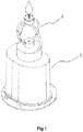
Fig. 1 is a schematic diagram of a connection structure of a fixing portion and a suspension portion in the present invention. -
Fig. 2 is a structural schematic diagram of a fixing portion inFig. 1 . -
Fig. 3 is a structural schematic diagram of a magnetic suspension portion inFig. 1 . -
Fig. 4 is a schematic diagram (section view) of an internal structure of a fixing portion and a suspension portion in the present invention. -
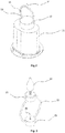
Fig. 5 is a schematic diagram (section view) of an internal structure of a laser projection lamp in the present invention. -
Fig. 6 is a schematic diagram of an amplified structure of a laser projection lamp in the present invention. -
Fig. 1 to Fig. 6 comprise afixing portion 1, abase 11, alug boss 12, afixed ring 13, aspike 14, anelectromagnet 15, a transmittingcoil 16, a maincontrol circuit board 17, apower source end 18, asecond LED bulb 19, amagnetic suspension portion 2, apendant 21, afloating ring 22, alamp base 23, afirst LED bulb 24, agroove 25, apermanent magnet 26, areceiving coil 27, anartificial diamond 28, alaser projection lamp 3, adetachable housing 31, aprojection sheet 311, aclamping groove 312, alaser tube 313, a throughhole 314, alead wire 32, a light-transmittingmirror 33 and ahousing 4. - In order to make the above purpose, features and advantages of the present invention more apparent and easier to understand, the present invention is further described in detail below in combination with the drawings and specific embodiments.
- As shown in
Fig.1 to Fig. 4 , in a specific embodiment, a swinging LED lamp with a wireless charging function provided by the present invention comprises afixing portion 1 and amagnetic suspension portion 2, wherein
thefixing portion 1 comprises abase 11 and alug boss 12 formed at an upper end of thebase 11. A maincontrol circuit board 17 and apower source end 18 are arranged in thebase 11. Anelectromagnet 15 and a transmittingcoil 16 are arranged in thelug boss 12. Theelectromagnet 15 and the transmittingcoil 16 are electrically connected with the power source end 18 through the maincontrol circuit board 17, respectively. Thelug boss 12 is connected with a fixedring 13 perpendicular to thelug boss 12. Aspike 14 is formed at a top end of the fixedring 13. - In the present embodiment, the power source end 18 is connected with a storage battery (not shown) arranged in the
base 11. The maincontrol circuit board 17 processes current outputted by the storage battery and then supplies the current to theelectromagnet 15 and the transmittingcoil 16. Certainly, in some other embodiments, the power source end 7 can also be connected with an external DC (Direct Current) or AC (Alternate Current) power source - A control knob (not shown) is arranged on an outer wall of the
base 11. The control knob is connected with the maincontrol circuit board 17. The control knob is used for controlling the magnitude of the current outputted by the maincontrol circuit board 17. - The
magnetic suspension portion 2 comprises apendant 21, a floatingring 22 and alamp base 23. Thependant 21 is connected to a bottom end of the floatingring 22. Thelamp base 23 is connected to a top end of the floatingring 22. Apermanent magnet 26 and a receivingcoil 27 are arranged in thependant 21. An LED control circuit board (not shown) and afirst LED bulb 24 electrically connected with the LED control circuit board are arranged on an upper end surface of thelamp base 23. The LED control circuit board is electrically connected with the receivingcoil 27. - A
groove 25 used in combination with thespike 14 is formed in a central position of a lower end surface of thelamp base 23. - A width of the
groove 25 is greater than that of thespike 14. A depth of thegroove 25 is greater than that of thespike 14. Thespike 14 can enter thegroove 25 and form point contact with thegroove 25. - The floating
ring 22 is sleeved on the fixedring 13. Thelamp base 23 is located above the fixedring 13. Thependant 21 is located above thelug boss 12. Thepermanent magnet 26 and theelectromagnet 15 in a power-on state are mutually exclusive. - When the
electromagnet 15 is not powered on or the current flowing through theelectromagnet 15 is less than a preset value, repulsive force between thepermanent magnet 26 and theelectromagnet 15 is smaller than self-gravity of themagnetic suspension portion 2. At this time, thelamp base 23 is supported at the upper end of the fixedring 13; thespike 14 enters thegroove 25 and forms the point contact with thegroove 25; and themagnetic suspension portion 2 realizes low-amplitude swinging in a balanced state. - When the current flowing through the
electromagnet 15 is greater than the preset the repulsive force between thepermanent magnet 26 and theelectromagnet 15 is greater than the self-gravity of themagnetic suspension portion 2. At this time, thebase 23 is suspended above the fixedring 13. - The swinging LED lamp with the wireless charging function in the present embodiment further comprises a
housing 4. The fixingportion 1 and themagnetic suspension portion 2 are located in the housing. In the present embodiment, the housing is a plastic housing. In some other embodiments, a paraffin housing, a glass housing and housings made of other materials can also be adopted. A hole matched with the lamp base is formed in the housing. - In the present embodiment, the
first LED bulb 24 comprises a lampshade (not shown) and an LED light-emitting component (not shown) arranged in the lampshade. The LED light-emitting component is electrically connected with the LED control circuit board. The LED control circuit board is connected with a receiving antenna. The receiving antenna is used for receiving a control signal emitted by an external control terminal (e.g., a remote controller, a mobile phone, etc.). The control circuit board controls a light-emitting state of thefirst LED bulb 24 based on the received control signal. The light-emitting state comprises a light color and a light intensity. - Specifically, the LED light-emitting component comprises a white-light LED and an RGB-light LED group. The control terminal controls the lighting of RGB single-color light LED or the mixed-color lighting of RG, GB, RB and RGB-light LEDs in a remote control way, so as to realize color change and meet needs of different lighting occasions. Certainly, the white-light LED can be lighted only to meet normal lighting needs.
- It should be noted that, the RGB color change of the LED light-emitting component is realized in the remote control way, which is a mature technology known by those ordinary skilled in the art and is not a novel technical solution to be protected by the present invention. Therefore, specific implementation processes are not described in detail in the present description. For example, a Chinese present invention patent (Publication Number:
CN201836681U ) discloses an LED lamp capable of remotely controlling RGB change, and provides a specific technical solution for performing different color lamp conversions on the LED lamp through a remote controller. The technical solution is also completely applicable to the present invention. - In order to improve the light-emitting effect of the present invention, in the present embodiment, an
artificial diamond 28 is inlaid on the upper end surface of thependant 21.Second LED bulbs 19 are symmetrically arranged on a left side and a right side of the fixedring 13. TheLED bulbs 19 are electrically connected with the LED control circuit board. - In the present embodiment, a structure of the
second LED bulbs 19 is the same as that of thefirst LED bulb 24. The LED control circuit board synchronously controls the light-emitting state of thesecond LED bulbs 19 based on the received control signal emitted by the external terminal. The light emitted by thesecond LED bulbs 19 is subjected to diffuse reflection on the surface of theartificial diamond 28, thereby creating a brilliant and fantastic reflection halation. Certainly, in some other embodiments, crystal stones and other types of diffuse reflection parts can also be adopted. - In order to further enhance the sense of science and technology of a lamp body, by referring to
Fig. 5 , alaser projection lamp 3 is further arranged in the housing. TheLED lamp 2 and thelaser projection lamp 3 are arranged on thebase 11 and are located in thehousing 4. TheLED lamp 2 and thelaser projection lamp 3 are electrically connected with the maincontrol circuit board 4 respectively. The maincontrol circuit board 17 processes the current outputted by the power source end 18 and then supplies the current to theLED lamp 2 and thelaser projection lamp 3. - In
Fig. 5 , in order to more clearly reflect the position of the laser projection lamp, some parts of the fixing portion and the magnetic suspension portion are omitted. - As shown in
Fig. 6 , thelaser projection lamp 3 comprises thedetachable housing 31 having an opened upper end as well as aprojection sheet 311 and alaser tube 313 arranged in thedetachable housing 31. The laser tube is located below the projection sheet. Thelaser tube 313 is electrically connected with the main control circuit board through alead wire 32. The projection sheet is made of a transparent material and is designed with patterns. When the laser tube is turned on, the patterns on the sheet can be projected onto the surface of an external object so as to produce a corresponding shade and shadow pattern on the surface of the object. - In the present embodiment, the
detachable housing 31 comprises a side wall and a bottom portion. Anannular clamping groove 312 protruding outwards is formed in the middle of the side wall. A throughhole 314 is formed in the bottom portion. The projection sheet is clamped in the clampinggroove 312. A lower end binding post of the laser tube penetrates through the through hole. - An opening 5 is formed in a housing position above the laser projection lamp, for emitting the light from the laser projection lamp upwards. The laser projection lamp is embedded at the housing position above the laser projection lamp through the detachable housing.
- A use method and a working principle of the present invention are as follows:
An initial state: a standby state, in which thelamp base 23 is supported at the upper end of the fixedring 13, and thespike 14 on the fixedring 13 enters thegroove 25 and forms the point contact with thegroove 25. - When the LED lamp needs to be used, the control knob is rotated forward so that the main
control circuit board 17 is connected with thepower source end 18. The maincontrol circuit board 17 supplies the current to theelectromagnet 15. Theelectromagnet 15 produces a magnetic field. The magnetic field and thepermanent magnet 26 are mutually exclusive. Meanwhile, an oscillation circuit on the maincontrol circuit board 17 converts the DC into the AC and transmits the AC to the transmittingcoil 16. The transmittingcoil 16 generates an alternating magnetic field under the action of the AC. The receivingcoil 27 generates electromagnetic induction under the action of the alternating magnetic field, generates the AC and conducts the AC to the LED control circuit board. Both thefirst LED bulb 24 and thesecond LED bulbs 19 electrically connected with the LED control circuit board emit light. - The light color and the light intensity of the light emitted by the
first LED bulb 24 and thesecond LED bulbs 19 can be flexibly adjusted through remote control of the external control terminal to meet various lighting needs. - The magnitude of the current outputted by the main
control circuit board 17 can be adjusted by adjusting a rotation amplitude of the control knob so as to control the state of themagnetic suspension portion 2. When the current outputted from the maincontrol circuit board 17 is less than a preset value, thelamp base 23 is supported at the upper end of the fixedring 13. Thespike 14 on the fixedring 13 enters thegroove 25 of thelamp base 23 and forms the point contact with thegroove 25. Themagnetic suspension portion 2 realizes low-amplitude swinging in a balanced state, so that thesuspension induction lamp 2 generates a dynamic light-emitting effect. When the current outputted from the main control circuit board 6 is greater than the preset value, thelamp base 23 is separated from the fixedring 13 and is suspended above the fixedring 13 to generate a suspension effect. - When the LED lamp needs to be turned off, the control knob is rotated reversely so that the main
control circuit board 17 is disconnected from the power source end 18, theelectromagnet 15 is de-energized, and the magnetic field on theelectromagnet 15 exclusive with thepermanent magnet 26 disappears correspondingly. Under the action of self-gravity, thelamp base 23 is returned to the upper end of the fixedring 13. Meanwhile, the transmittingcoil 16 loses the alternating magnetic field, the receivingcoil 27 correspondingly loses the electromagnetic induction and does not generate the AC, and thefirst LED bulb 24 and thesecond LED bulbs 19 are de-energized to be turned off. - The present invention is described above in detail in a certain particularity. Those ordinary skilled in the art should understand that descriptions in embodiments are merely exemplary, and all changes made without departing from the scope of the present invention should belong to the protection scope of the present invention. The protection scope required to be protected by the present invention is limited by claims, rather than the above descriptions in embodiments.
Claims (13)
- A swinging LED lamp with a wireless charging function, comprising:a fixing portion (1) comprising a base (11) and a lug boss (12) formed at an upper end of the base (11), wherein a main control circuit board (17) and a power source end (18) are arranged in the base (11); an electromagnet (15) and a transmitting coil (16) are arranged in the lug boss (12); the electromagnet (15) and the transmitting coil (16) are electrically connected with the power source end (18) through the main control circuit board (17) respectively; anda magnetic suspension portion (2), comprising a permanent magnet (26) and a receiving coil (27), an LED control circuit board and a first LED bulb (24) electrically connected with the LED control circuit board; the LED control circuit board electrically connected with the receiving coil (27), with the permanent magnet (26) and the electromagnet (15) in a power-on state being mutually exclusive; characterized in that,the lug boss (12) is connected with a fixed ring (13) perpendicular to the lug boss (12); and a spike (14) is formed at a top end of the fixed ring (13); andthe magnetic suspension portion (2) comprising a pendant (21), a floating ring (22) and a lamp base (23), wherein the pendant (21) is connected to a bottom end of the floating ring (22); the lamp base (23) is connected to a top end of the floating ring (22); the permanent magnet (26) and the receiving coil (27) are arranged in the pendant (21); the LED control circuit board and the first LED bulb (24) are arranged on an upper end surface of the lamp base (23); a groove (25) used in combination with the spike (14) is formed in a central position of a lower end surface of the lamp base (23); a width of the groove (25) is greater than a width of the spike (14); a depth of the groove (25) is smaller than a height of the spike (14); and after the spike (14) enters the groove (25), the spike (14) and the groove (25) form point contact; andthe floating ring (22) is sleeved on the fixed ring (13); the lamp base (23) is located above the fixed ring (13); the pendant (21) is located above the lug boss (12).
- The LED lamp according to claim 1, characterized in that, the first LED bulb (24) comprises a lampshade and an LED light-emitting component arranged in the lampshade; the LED light-emitting component is electrically connected with an LED control circuit; the LED control circuit is connected with a receiving antenna; the receiving antenna is used for receiving a control signal emitted by an external control terminal; and the control circuit controls a light-emitting state of the LED light-emitting component based on the received control signal.
- The LED lamp according to claim 2, characterized in that, the LED light-emitting component comprises a white-light LED and an RGB-light LED group; and the LED control circuit controls a lighting combination of the white-light LED and the RGB-light LED group to control a light-emitting state of the LED light-emitting component.
- The LED lamp according to claim 2, characterized in that, a diffuse reflection part is arranged on the upper end surface of the pendant (21); second LED bulbs (19) are symmetrically arranged on a left side and a right side of the fixed ring (13); and the second LED bulbs (19) are electrically connected with the LED control circuit board.
- The LED lamp according to claim 4, characterized in that, the diffuse reflection part is an artificial diamond (28).
- The LED lamp according to claim 1, characterized in that, the power source end (18) is connected with an external Direct Current power source.
- The LED lamp according to claim 1, characterized in that, the power source end (18) is connected with a storage battery arranged in the base (11).
- The LED lamp according to claim 1, characterized in that, the LED lamp further comprises a housing (4) for accommodating the fixing portion (1) and the magnetic suspension portion (2).
- The LED lamp according to claim 8, characterized in that, the LED lamp further comprises a laser projection lamp (3) arranged on the base (11) and located in the housing (4), and the laser projection lamp (3) is electrically connected with the main control circuit board (17).
- The LED lamp according to claim 9, characterized in that, the laser projection lamp (3) comprises a detachable housing (31) having an opened upper end as well as a projection sheet (311) and a laser tube (313) arranged in the detachable housing (31); the laser tube (313) is located below the projection sheet (311); and the laser tube (313) is electrically connected with the main control circuit board (17).
- The LED lamp according to claim 10, characterized in that, the detachable housing (31) comprises a side wall and a bottom portion; an annular clamping groove (312) protruding outwards is formed in the middle of the side wall; a through hole (314) is formed in the bottom portion; the projection sheet (311) is clamped in the clamping groove (312); and the laser tube (313) is penetrated into the bottom portion through the through hole (314).
- The LED lamp according to claim 8, characterized in that, the housing (4) is a plastic housing.
- The LED lamp according to claim 8, characterized in that, the housing (4) is a paraffin housing.
Applications Claiming Priority (2)
| Application Number | Priority Date | Filing Date | Title |
|---|---|---|---|
| CN201720606310.7U CN207049809U (en) | 2017-05-26 | 2017-05-26 | A kind of LED with radium-shine projecting function |
| CN201720600487.6U CN207049777U (en) | 2017-05-26 | 2017-05-26 | It is a kind of to wave LED with wireless charging function |
Publications (2)
| Publication Number | Publication Date |
|---|---|
| EP3406964A1 EP3406964A1 (en) | 2018-11-28 |
| EP3406964B1 true EP3406964B1 (en) | 2020-05-06 |
Family
ID=59350692
Family Applications (1)
| Application Number | Title | Priority Date | Filing Date |
|---|---|---|---|
| EP17181087.2A Active EP3406964B1 (en) | 2017-05-26 | 2017-07-12 | Swinging led lamp with wireless charging function |
Country Status (2)
| Country | Link |
|---|---|
| US (1) | US10352538B2 (en) |
| EP (1) | EP3406964B1 (en) |
Families Citing this family (4)
| Publication number | Priority date | Publication date | Assignee | Title |
|---|---|---|---|---|
| CN210267016U (en) * | 2019-07-03 | 2020-04-07 | 极光国际有限公司 | LED candle lamp |
| CN111550728B (en) * | 2020-04-22 | 2022-02-01 | 湖南城市学院 | Household induction type solar street lamp |
| CN214275571U (en) * | 2020-08-17 | 2021-09-24 | 广东亚一半导体应用科技有限公司 | Magnetic suspension supporting structure and light-emitting device and light guide device using same |
| JP7050372B1 (en) | 2021-06-23 | 2022-04-08 | 株式会社アンビエンテック | Lighting equipment with lenses for luminaires |
Citations (1)
| Publication number | Priority date | Publication date | Assignee | Title |
|---|---|---|---|---|
| CN202708961U (en) * | 2011-04-19 | 2013-01-30 | 广东亚一照明科技有限公司 | Simulation light emitting diode (LED) candlestick lamp |
Family Cites Families (10)
| Publication number | Priority date | Publication date | Assignee | Title |
|---|---|---|---|---|
| SE310630B (en) * | 1968-01-10 | 1969-05-12 | B Beckman | |
| US7261455B2 (en) * | 2004-08-10 | 2007-08-28 | Disney Enterprises, Inc. | System and method for generating a flickering flame effect |
| CN101865413B (en) * | 2010-06-28 | 2012-08-01 | 李晓锋 | Electronic luminescent device for simulating true fire and method for simulating true fire by same |
| CN201836681U (en) | 2010-09-13 | 2011-05-18 | 廖炳明 | LED lamp capable of remotely controlling RGB (Red, Green and Blue) conversion |
| KR101174246B1 (en) * | 2011-12-12 | 2012-08-14 | 이종걸 | Portable electric candle having lamp for pendulum and rotation movement |
| CN202791780U (en) * | 2012-08-28 | 2013-03-13 | 辜悯 | Electronic candle |
| EP2952066A4 (en) * | 2013-01-30 | 2017-02-22 | Luminara Worldwide, LLC | Systems and methods for controlling a plurality of electric candles |
| US9915402B2 (en) * | 2013-07-30 | 2018-03-13 | Shenzhen Yameite Technology Co. Ltd. | Illumination devices |
| CN205227190U (en) * | 2015-10-30 | 2016-05-11 | 南通亚泰蜡业工艺品有限公司 | Swinging electronic candle |
| CN205619160U (en) * | 2016-03-23 | 2016-10-05 | 潘燕 | Magnetic suspension LED lamp with wireless function of charging |
-
2017
- 2017-07-12 EP EP17181087.2A patent/EP3406964B1/en active Active
- 2017-07-18 US US15/653,499 patent/US10352538B2/en not_active Expired - Fee Related
Patent Citations (1)
| Publication number | Priority date | Publication date | Assignee | Title |
|---|---|---|---|---|
| CN202708961U (en) * | 2011-04-19 | 2013-01-30 | 广东亚一照明科技有限公司 | Simulation light emitting diode (LED) candlestick lamp |
Also Published As
| Publication number | Publication date |
|---|---|
| EP3406964A1 (en) | 2018-11-28 |
| US10352538B2 (en) | 2019-07-16 |
| US20180340678A1 (en) | 2018-11-29 |
Similar Documents
| Publication | Publication Date | Title |
|---|---|---|
| EP3406964B1 (en) | Swinging led lamp with wireless charging function | |
| US20150308643A1 (en) | Electronic light-emitting device | |
| US20180283633A1 (en) | Flameless electronic candle | |
| WO2016011806A1 (en) | Led simulated flame candle | |
| US9810405B2 (en) | Electronic candle | |
| WO2016106804A1 (en) | Intelligent light-emitting music device capable of simulating candlelight | |
| EP3447367B1 (en) | Remote control and lighting device | |
| CN104534396A (en) | Light-emitting device simulating candlelight | |
| US10506679B2 (en) | LED light and electronic candle | |
| CN204285290U (en) | A kind of light-emitting device of simulating candle light | |
| CN109027730B (en) | Combined LED lighting system | |
| US10517159B2 (en) | Control device | |
| WO2016101345A1 (en) | Light-emitting device simulating candlelight | |
| CN207034713U (en) | The straight rod portable lamp of slice formula | |
| US11143373B2 (en) | Movable flame assembly and simulated flame device comprising the same | |
| CN204300965U (en) | A kind of intelligent music light-emitting device of simulating candle light | |
| CN207049777U (en) | It is a kind of to wave LED with wireless charging function | |
| KR101090564B1 (en) | Led lighting apparatus with air levitation system | |
| JP2013004509A (en) | Led lighting fixture | |
| CN205690174U (en) | A kind of light fixture of artificial scene | |
| CN204285291U (en) | A kind of light-emitting device of simulating candle light | |
| CN213019235U (en) | Magnetic wireless LED lamp with playing function | |
| CN215174626U (en) | Bar table lamp | |
| CN217031095U (en) | LED lamp pearl with adjustting of lighteness function | |
| CN210688081U (en) | Electronic candle |
Legal Events
| Date | Code | Title | Description |
|---|---|---|---|
| PUAI | Public reference made under article 153(3) epc to a published international application that has entered the european phase |
Free format text: ORIGINAL CODE: 0009012 |
|
| STAA | Information on the status of an ep patent application or granted ep patent |
Free format text: STATUS: REQUEST FOR EXAMINATION WAS MADE |
|
| 17P | Request for examination filed |
Effective date: 20170721 |
|
| AK | Designated contracting states |
Kind code of ref document: A1 Designated state(s): AL AT BE BG CH CY CZ DE DK EE ES FI FR GB GR HR HU IE IS IT LI LT LU LV MC MK MT NL NO PL PT RO RS SE SI SK SM TR |
|
| AX | Request for extension of the european patent |
Extension state: BA ME |
|
| GRAP | Despatch of communication of intention to grant a patent |
Free format text: ORIGINAL CODE: EPIDOSNIGR1 |
|
| STAA | Information on the status of an ep patent application or granted ep patent |
Free format text: STATUS: GRANT OF PATENT IS INTENDED |
|
| INTG | Intention to grant announced |
Effective date: 20191217 |
|
| GRAS | Grant fee paid |
Free format text: ORIGINAL CODE: EPIDOSNIGR3 |
|
| GRAA | (expected) grant |
Free format text: ORIGINAL CODE: 0009210 |
|
| STAA | Information on the status of an ep patent application or granted ep patent |
Free format text: STATUS: THE PATENT HAS BEEN GRANTED |
|
| AK | Designated contracting states |
Kind code of ref document: B1 Designated state(s): AL AT BE BG CH CY CZ DE DK EE ES FI FR GB GR HR HU IE IS IT LI LT LU LV MC MK MT NL NO PL PT RO RS SE SI SK SM TR |
|
| REG | Reference to a national code |
Ref country code: GB Ref legal event code: FG4D |
|
| REG | Reference to a national code |
Ref country code: CH Ref legal event code: EP Ref country code: AT Ref legal event code: REF Ref document number: 1267318 Country of ref document: AT Kind code of ref document: T Effective date: 20200515 |
|
| REG | Reference to a national code |
Ref country code: DE Ref legal event code: R096 Ref document number: 602017016055 Country of ref document: DE |
|
| REG | Reference to a national code |
Ref country code: IE Ref legal event code: FG4D |
|
| REG | Reference to a national code |
Ref country code: LT Ref legal event code: MG4D |
|
| REG | Reference to a national code |
Ref country code: NL Ref legal event code: MP Effective date: 20200506 |
|
| PG25 | Lapsed in a contracting state [announced via postgrant information from national office to epo] |
Ref country code: GR Free format text: LAPSE BECAUSE OF FAILURE TO SUBMIT A TRANSLATION OF THE DESCRIPTION OR TO PAY THE FEE WITHIN THE PRESCRIBED TIME-LIMIT Effective date: 20200807 Ref country code: FI Free format text: LAPSE BECAUSE OF FAILURE TO SUBMIT A TRANSLATION OF THE DESCRIPTION OR TO PAY THE FEE WITHIN THE PRESCRIBED TIME-LIMIT Effective date: 20200506 Ref country code: LT Free format text: LAPSE BECAUSE OF FAILURE TO SUBMIT A TRANSLATION OF THE DESCRIPTION OR TO PAY THE FEE WITHIN THE PRESCRIBED TIME-LIMIT Effective date: 20200506 Ref country code: PT Free format text: LAPSE BECAUSE OF FAILURE TO SUBMIT A TRANSLATION OF THE DESCRIPTION OR TO PAY THE FEE WITHIN THE PRESCRIBED TIME-LIMIT Effective date: 20200907 Ref country code: IS Free format text: LAPSE BECAUSE OF FAILURE TO SUBMIT A TRANSLATION OF THE DESCRIPTION OR TO PAY THE FEE WITHIN THE PRESCRIBED TIME-LIMIT Effective date: 20200906 Ref country code: NO Free format text: LAPSE BECAUSE OF FAILURE TO SUBMIT A TRANSLATION OF THE DESCRIPTION OR TO PAY THE FEE WITHIN THE PRESCRIBED TIME-LIMIT Effective date: 20200806 Ref country code: SE Free format text: LAPSE BECAUSE OF FAILURE TO SUBMIT A TRANSLATION OF THE DESCRIPTION OR TO PAY THE FEE WITHIN THE PRESCRIBED TIME-LIMIT Effective date: 20200506 |
|
| PGFP | Annual fee paid to national office [announced via postgrant information from national office to epo] |
Ref country code: DE Payment date: 20200604 Year of fee payment: 4 |
|
| PG25 | Lapsed in a contracting state [announced via postgrant information from national office to epo] |
Ref country code: HR Free format text: LAPSE BECAUSE OF FAILURE TO SUBMIT A TRANSLATION OF THE DESCRIPTION OR TO PAY THE FEE WITHIN THE PRESCRIBED TIME-LIMIT Effective date: 20200506 Ref country code: RS Free format text: LAPSE BECAUSE OF FAILURE TO SUBMIT A TRANSLATION OF THE DESCRIPTION OR TO PAY THE FEE WITHIN THE PRESCRIBED TIME-LIMIT Effective date: 20200506 Ref country code: LV Free format text: LAPSE BECAUSE OF FAILURE TO SUBMIT A TRANSLATION OF THE DESCRIPTION OR TO PAY THE FEE WITHIN THE PRESCRIBED TIME-LIMIT Effective date: 20200506 Ref country code: BG Free format text: LAPSE BECAUSE OF FAILURE TO SUBMIT A TRANSLATION OF THE DESCRIPTION OR TO PAY THE FEE WITHIN THE PRESCRIBED TIME-LIMIT Effective date: 20200806 |
|
| REG | Reference to a national code |
Ref country code: AT Ref legal event code: MK05 Ref document number: 1267318 Country of ref document: AT Kind code of ref document: T Effective date: 20200506 |
|
| PG25 | Lapsed in a contracting state [announced via postgrant information from national office to epo] |
Ref country code: AL Free format text: LAPSE BECAUSE OF FAILURE TO SUBMIT A TRANSLATION OF THE DESCRIPTION OR TO PAY THE FEE WITHIN THE PRESCRIBED TIME-LIMIT Effective date: 20200506 Ref country code: NL Free format text: LAPSE BECAUSE OF FAILURE TO SUBMIT A TRANSLATION OF THE DESCRIPTION OR TO PAY THE FEE WITHIN THE PRESCRIBED TIME-LIMIT Effective date: 20200506 |
|
| PG25 | Lapsed in a contracting state [announced via postgrant information from national office to epo] |
Ref country code: ES Free format text: LAPSE BECAUSE OF FAILURE TO SUBMIT A TRANSLATION OF THE DESCRIPTION OR TO PAY THE FEE WITHIN THE PRESCRIBED TIME-LIMIT Effective date: 20200506 Ref country code: AT Free format text: LAPSE BECAUSE OF FAILURE TO SUBMIT A TRANSLATION OF THE DESCRIPTION OR TO PAY THE FEE WITHIN THE PRESCRIBED TIME-LIMIT Effective date: 20200506 Ref country code: RO Free format text: LAPSE BECAUSE OF FAILURE TO SUBMIT A TRANSLATION OF THE DESCRIPTION OR TO PAY THE FEE WITHIN THE PRESCRIBED TIME-LIMIT Effective date: 20200506 Ref country code: CZ Free format text: LAPSE BECAUSE OF FAILURE TO SUBMIT A TRANSLATION OF THE DESCRIPTION OR TO PAY THE FEE WITHIN THE PRESCRIBED TIME-LIMIT Effective date: 20200506 Ref country code: SM Free format text: LAPSE BECAUSE OF FAILURE TO SUBMIT A TRANSLATION OF THE DESCRIPTION OR TO PAY THE FEE WITHIN THE PRESCRIBED TIME-LIMIT Effective date: 20200506 Ref country code: IT Free format text: LAPSE BECAUSE OF FAILURE TO SUBMIT A TRANSLATION OF THE DESCRIPTION OR TO PAY THE FEE WITHIN THE PRESCRIBED TIME-LIMIT Effective date: 20200506 Ref country code: EE Free format text: LAPSE BECAUSE OF FAILURE TO SUBMIT A TRANSLATION OF THE DESCRIPTION OR TO PAY THE FEE WITHIN THE PRESCRIBED TIME-LIMIT Effective date: 20200506 Ref country code: DK Free format text: LAPSE BECAUSE OF FAILURE TO SUBMIT A TRANSLATION OF THE DESCRIPTION OR TO PAY THE FEE WITHIN THE PRESCRIBED TIME-LIMIT Effective date: 20200506 |
|
| REG | Reference to a national code |
Ref country code: DE Ref legal event code: R097 Ref document number: 602017016055 Country of ref document: DE |
|
| PG25 | Lapsed in a contracting state [announced via postgrant information from national office to epo] |
Ref country code: MC Free format text: LAPSE BECAUSE OF FAILURE TO SUBMIT A TRANSLATION OF THE DESCRIPTION OR TO PAY THE FEE WITHIN THE PRESCRIBED TIME-LIMIT Effective date: 20200506 Ref country code: SK Free format text: LAPSE BECAUSE OF FAILURE TO SUBMIT A TRANSLATION OF THE DESCRIPTION OR TO PAY THE FEE WITHIN THE PRESCRIBED TIME-LIMIT Effective date: 20200506 Ref country code: PL Free format text: LAPSE BECAUSE OF FAILURE TO SUBMIT A TRANSLATION OF THE DESCRIPTION OR TO PAY THE FEE WITHIN THE PRESCRIBED TIME-LIMIT Effective date: 20200506 |
|
| REG | Reference to a national code |
Ref country code: CH Ref legal event code: PL |
|
| PLBE | No opposition filed within time limit |
Free format text: ORIGINAL CODE: 0009261 |
|
| STAA | Information on the status of an ep patent application or granted ep patent |
Free format text: STATUS: NO OPPOSITION FILED WITHIN TIME LIMIT |
|
| 26N | No opposition filed |
Effective date: 20210209 |
|
| REG | Reference to a national code |
Ref country code: BE Ref legal event code: MM Effective date: 20200731 |
|
| PG25 | Lapsed in a contracting state [announced via postgrant information from national office to epo] |
Ref country code: FR Free format text: LAPSE BECAUSE OF NON-PAYMENT OF DUE FEES Effective date: 20200731 Ref country code: LU Free format text: LAPSE BECAUSE OF NON-PAYMENT OF DUE FEES Effective date: 20200712 Ref country code: LI Free format text: LAPSE BECAUSE OF NON-PAYMENT OF DUE FEES Effective date: 20200731 Ref country code: CH Free format text: LAPSE BECAUSE OF NON-PAYMENT OF DUE FEES Effective date: 20200731 |
|
| PG25 | Lapsed in a contracting state [announced via postgrant information from national office to epo] |
Ref country code: BE Free format text: LAPSE BECAUSE OF NON-PAYMENT OF DUE FEES Effective date: 20200731 Ref country code: SI Free format text: LAPSE BECAUSE OF FAILURE TO SUBMIT A TRANSLATION OF THE DESCRIPTION OR TO PAY THE FEE WITHIN THE PRESCRIBED TIME-LIMIT Effective date: 20200506 |
|
| PG25 | Lapsed in a contracting state [announced via postgrant information from national office to epo] |
Ref country code: IE Free format text: LAPSE BECAUSE OF NON-PAYMENT OF DUE FEES Effective date: 20200712 |
|
| REG | Reference to a national code |
Ref country code: DE Ref legal event code: R119 Ref document number: 602017016055 Country of ref document: DE |
|
| GBPC | Gb: european patent ceased through non-payment of renewal fee |
Effective date: 20210712 |
|
| PG25 | Lapsed in a contracting state [announced via postgrant information from national office to epo] |
Ref country code: GB Free format text: LAPSE BECAUSE OF NON-PAYMENT OF DUE FEES Effective date: 20210712 Ref country code: DE Free format text: LAPSE BECAUSE OF NON-PAYMENT OF DUE FEES Effective date: 20220201 |
|
| PG25 | Lapsed in a contracting state [announced via postgrant information from national office to epo] |
Ref country code: TR Free format text: LAPSE BECAUSE OF FAILURE TO SUBMIT A TRANSLATION OF THE DESCRIPTION OR TO PAY THE FEE WITHIN THE PRESCRIBED TIME-LIMIT Effective date: 20200506 Ref country code: MT Free format text: LAPSE BECAUSE OF FAILURE TO SUBMIT A TRANSLATION OF THE DESCRIPTION OR TO PAY THE FEE WITHIN THE PRESCRIBED TIME-LIMIT Effective date: 20200506 Ref country code: CY Free format text: LAPSE BECAUSE OF FAILURE TO SUBMIT A TRANSLATION OF THE DESCRIPTION OR TO PAY THE FEE WITHIN THE PRESCRIBED TIME-LIMIT Effective date: 20200506 |
|
| PG25 | Lapsed in a contracting state [announced via postgrant information from national office to epo] |
Ref country code: MK Free format text: LAPSE BECAUSE OF FAILURE TO SUBMIT A TRANSLATION OF THE DESCRIPTION OR TO PAY THE FEE WITHIN THE PRESCRIBED TIME-LIMIT Effective date: 20200506 |