EP3406904A1 - Centrifugal compression test device - Google Patents
Centrifugal compression test device Download PDFInfo
- Publication number
- EP3406904A1 EP3406904A1 EP17766725.0A EP17766725A EP3406904A1 EP 3406904 A1 EP3406904 A1 EP 3406904A1 EP 17766725 A EP17766725 A EP 17766725A EP 3406904 A1 EP3406904 A1 EP 3406904A1
- Authority
- EP
- European Patent Office
- Prior art keywords
- flow path
- axis
- radial direction
- introduction
- rotary shaft
- Prior art date
- Legal status (The legal status is an assumption and is not a legal conclusion. Google has not performed a legal analysis and makes no representation as to the accuracy of the status listed.)
- Granted
Links
Images

Classifications
-
- F—MECHANICAL ENGINEERING; LIGHTING; HEATING; WEAPONS; BLASTING
- F04—POSITIVE - DISPLACEMENT MACHINES FOR LIQUIDS; PUMPS FOR LIQUIDS OR ELASTIC FLUIDS
- F04D—NON-POSITIVE-DISPLACEMENT PUMPS
- F04D29/00—Details, component parts, or accessories
- F04D29/40—Casings; Connections of working fluid
- F04D29/42—Casings; Connections of working fluid for radial or helico-centrifugal pumps
- F04D29/4206—Casings; Connections of working fluid for radial or helico-centrifugal pumps especially adapted for elastic fluid pumps
- F04D29/4213—Casings; Connections of working fluid for radial or helico-centrifugal pumps especially adapted for elastic fluid pumps suction ports
-
- F—MECHANICAL ENGINEERING; LIGHTING; HEATING; WEAPONS; BLASTING
- F04—POSITIVE - DISPLACEMENT MACHINES FOR LIQUIDS; PUMPS FOR LIQUIDS OR ELASTIC FLUIDS
- F04D—NON-POSITIVE-DISPLACEMENT PUMPS
- F04D27/00—Control, e.g. regulation, of pumps, pumping installations or pumping systems specially adapted for elastic fluids
- F04D27/001—Testing thereof; Determination or simulation of flow characteristics; Stall or surge detection, e.g. condition monitoring
-
- F—MECHANICAL ENGINEERING; LIGHTING; HEATING; WEAPONS; BLASTING
- F04—POSITIVE - DISPLACEMENT MACHINES FOR LIQUIDS; PUMPS FOR LIQUIDS OR ELASTIC FLUIDS
- F04D—NON-POSITIVE-DISPLACEMENT PUMPS
- F04D17/00—Radial-flow pumps, e.g. centrifugal pumps; Helico-centrifugal pumps
- F04D17/08—Centrifugal pumps
- F04D17/10—Centrifugal pumps for compressing or evacuating
- F04D17/12—Multi-stage pumps
-
- F—MECHANICAL ENGINEERING; LIGHTING; HEATING; WEAPONS; BLASTING
- F04—POSITIVE - DISPLACEMENT MACHINES FOR LIQUIDS; PUMPS FOR LIQUIDS OR ELASTIC FLUIDS
- F04D—NON-POSITIVE-DISPLACEMENT PUMPS
- F04D29/00—Details, component parts, or accessories
- F04D29/40—Casings; Connections of working fluid
- F04D29/42—Casings; Connections of working fluid for radial or helico-centrifugal pumps
- F04D29/44—Fluid-guiding means, e.g. diffusers
- F04D29/441—Fluid-guiding means, e.g. diffusers especially adapted for elastic fluid pumps
- F04D29/444—Bladed diffusers
-
- F—MECHANICAL ENGINEERING; LIGHTING; HEATING; WEAPONS; BLASTING
- F04—POSITIVE - DISPLACEMENT MACHINES FOR LIQUIDS; PUMPS FOR LIQUIDS OR ELASTIC FLUIDS
- F04D—NON-POSITIVE-DISPLACEMENT PUMPS
- F04D29/00—Details, component parts, or accessories
- F04D29/66—Combating cavitation, whirls, noise, vibration or the like; Balancing
- F04D29/68—Combating cavitation, whirls, noise, vibration or the like; Balancing by influencing boundary layers
- F04D29/681—Combating cavitation, whirls, noise, vibration or the like; Balancing by influencing boundary layers especially adapted for elastic fluid pumps
- F04D29/684—Combating cavitation, whirls, noise, vibration or the like; Balancing by influencing boundary layers especially adapted for elastic fluid pumps by fluid injection
-
- F—MECHANICAL ENGINEERING; LIGHTING; HEATING; WEAPONS; BLASTING
- F04—POSITIVE - DISPLACEMENT MACHINES FOR LIQUIDS; PUMPS FOR LIQUIDS OR ELASTIC FLUIDS
- F04D—NON-POSITIVE-DISPLACEMENT PUMPS
- F04D29/00—Details, component parts, or accessories
- F04D29/70—Suction grids; Strainers; Dust separation; Cleaning
- F04D29/701—Suction grids; Strainers; Dust separation; Cleaning especially adapted for elastic fluid pumps
-
- F—MECHANICAL ENGINEERING; LIGHTING; HEATING; WEAPONS; BLASTING
- F05—INDEXING SCHEMES RELATING TO ENGINES OR PUMPS IN VARIOUS SUBCLASSES OF CLASSES F01-F04
- F05D—INDEXING SCHEME FOR ASPECTS RELATING TO NON-POSITIVE-DISPLACEMENT MACHINES OR ENGINES, GAS-TURBINES OR JET-PROPULSION PLANTS
- F05D2250/00—Geometry
- F05D2250/50—Inlet or outlet
- F05D2250/51—Inlet
Definitions
- the first side surface 14a is disposed in the inlet space 14 on the side close to the first end portion 2a in the axis O direction (a first side in the axial direction).
- the first side surface 14a is formed to be disposed gradually closer to the second end portion 2b in the axis O direction as it approaches the rotary shaft 2.
Landscapes
- Engineering & Computer Science (AREA)
- Mechanical Engineering (AREA)
- General Engineering & Computer Science (AREA)
- Structures Of Non-Positive Displacement Pumps (AREA)
- Control Of Positive-Displacement Pumps (AREA)
Abstract
Description
- The present invention relates to a centrifugal compression test device.
- Priority is claimed on Japanese Patent Application No.
2016-056046, filed March 18, 2016 - A uniaxial multistage centrifugal compressor in which a plurality of impellers are installed on the same rotary shaft to boost a fluid by stages is known. In such a uniaxial multistage centrifugal compressor, so-called interstage inflow in which a working fluid obtained by extracting a fluid inserted from the outside or a fluid boosted by a rear stage impeller flows into an inflow port through which a working fluid flows into the impellers may be performed.
- Patent Document 1 discloses that, in a two-stage centrifugal compressor, in order to additionally supply a gas, an interstage inflow path is formed.
- [Patent Document 1]
Japanese Unexamined Patent Application, First Publication No.2013-194687 - For example, in the above-mentioned uniaxial multistage centrifugal compressor, in general, performance prediction is performed based on a verification test result by a single stage test device. For this reason, even when performance prediction is performed based on a verification test by a single stage test device in which interstage inflow is not provided, reliability of the prediction result may be low. In addition, in a multistage centrifugal compressor having interstage inflow, the interstage inflow is mainly disposed in an inflow port of an impeller at second and subsequent stages. For this reason, even when a single stage test device in which interstage inflow is formed is devised, the same conditions as in a real machine may not be obtained.
- The present invention is directed to providing a centrifugal compression test device capable of improving performance prediction accuracy by performing a verification test having high reliability on a single stage impeller when performance prediction of a centrifugal compressor having interstage inflow is performed.
- According to a first aspect of the present invention, a centrifugal compression test device includes a rotary shaft, a bearing, a driving source, an impeller, a flow path forming section and an inlet space forming section. The rotary shaft extends in an axial direction. The bearing rotatably supports the rotary shaft about an axis thereof. The driving source drives the rotary shaft around the axis. The impeller is fixed to an outer circumferential surface of the rotary shaft and configured to pump a fluid flowing from a first side in an axial direction to an outside in a radial direction while rotating together with the rotary shaft. The flow path forming section forms an introduction flow path, an inlet flow path and an interstage inflow path. The introduction flow path guides a fluid from the outside in the radial direction toward the inside in the radial direction at the first side of the impeller in the axial direction. The inlet flow path is connected to the introduction flow path and configured to guide the fluid to the impeller from the first side in the axial direction. The interstage inflow path extends from the outside toward the inside in the radial direction and is connected to the inlet flow path at a second side of the introduction flow path in the axial direction. The inlet space forming section has an introduction opening section through which a fluid is introduced from a part in the circumferential direction and outside in the radial direction at the first side of the introduction flow path in the axial direction. The inlet space forming section further forms an annular shape about the axis, and a front end of the introduction flow path is connected to the inlet space forming section.
- According to the above-mentioned configuration, under the same condition as in a real machine including an interstage inflow path, an intermediate stage including the interstage inflow path can be simulated and a verification test by a single stage test device can be performed. As a result, performance prediction accuracy can be improved.
- According to a second aspect of the present invention, in the first aspect, the centrifugal compression test device may include a pressure loss application unit configured to apply a pressure loss to a fluid flowing into the introduction flow path.
- According to the above-mentioned configuration, since a pressure loss can be applied to the fluid flowing into the introduction flow path using the pressure loss application unit, a flow rate of the fluid flowing into the introduction flow path can be uniformized in the circumferential direction. As a result, an environment similar to a real machine can be created.
- According to a third aspect of the present invention, in the centrifugal compression test device in the second aspect, the pressure loss application unit may be installed at only a side closer to the introduction opening section than the axis in the circumferential direction about the axis.
- For example, while a flow rate of the fluid increases toward a place close to the introduction opening section in the circumferential direction in the introduction flow path and deviation occurs in the flow rate of the fluid in the circumferential direction, the deviation in the flow rate can be further uniformized by the pressure loss application unit. As a result, an environment more similar to a real machine can be created.
- According to a fourth aspect of the present invention, in any one aspect of the first to third aspects, the centrifugal compression test device may include a return flow path forming section and an outlet space forming section. The return flow path forming section forms a return flow path extending inward in the radial direction after extending from the impeller toward the outside in the radial direction. The outlet space forming section through which a fluid is discharged from a part in the circumferential direction and the outside in the radial direction forms an annular shape about the axis at a second side of the return flow path in the axial direction. A rear end of the return flow path is further connected to the outlet space forming section.
- According to the above-mentioned configuration, an environment more similar to a real machine can be created even on the second side in the axial direction from the impeller. As a result, reliability in a test result of a verification test by a single stage test device can be improved.
- According to the centrifugal compression test device, when performance prediction of the centrifugal compressor having interstage inflow is performed, a verification test having high reliability can be performed on a single stage impeller, and performance prediction accuracy can be improved.
-
-
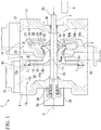
Fig. 1 is a cross-sectional view of a centrifugal compression test device according to an embodiment of the present invention. -
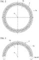
Fig. 2 is a front view of a pressure loss application unit according to the embodiment of the present invention. -
Fig. 3 is a view of a pressure loss application unit according to a modified example of the embodiment of the present invention, corresponding toFig. 2 . -
Fig. 4 is an enlarged view showing an arrangement of the pressure loss application unit of the embodiment of the present invention. -
Fig. 5 is an enlarged view showing another aspect of the pressure loss application unit of the embodiment of the present invention, corresponding toFig. 4 . - Hereinafter, a centrifugal compression test device according to an embodiment of the present invention will be described with reference to the accompanying drawings.
-
Fig. 1 is a cross-sectional view of a centrifugal compression test device according to the embodiment of the present invention. - As shown in
Fig. 1 , a centrifugal compression test device 1 according to the embodiment includes arotary shaft 2,bearings driving source 6 and a pressureloss application unit 7. - The
rotary shaft 2 is rotatably supported by thebearings bearings bearings rotary shaft 2 while restricting displacement in a radial direction and an axial direction thereof. The casing 4 supports afirst end portion 2a and asecond end portion 2b in an axis O direction of therotary shaft 2 via thebearings rotary shaft 2, the impeller 5, and so on. - The casing 4 includes an inlet
space forming section 10, a flowpath forming section 11, a return flowpath forming section 12 and an outletspace forming section 13. - The inlet
space forming section 10 is annularly formed about the axis O. The inletspace forming section 10 forms anannular inlet space 14 therein around therotary shaft 2. The inletspace forming section 10 has an introduction openingsection 15 formed in a part thereof in a circumferential direction. A fluid can be introduced into theinlet space 14 from the outside in the radial direction via theintroduction opening section 15. - The
inlet space 14 in the embodiment is formed by afirst side surface 14a, asecond side surface 14b, an innercircumferential surface 14c, and an outer circumferential surface 2c of therotary shaft 2. - The
first side surface 14a is disposed in theinlet space 14 on the side close to thefirst end portion 2a in the axis O direction (a first side in the axial direction). Thefirst side surface 14a is formed to be disposed gradually closer to thesecond end portion 2b in the axis O direction as it approaches therotary shaft 2. - The
second side surface 14b is disposed in theinlet space 14 on the side close to thesecond end portion 2b (a second side in the axial direction). Thesecond side surface 14b is formed mainly on a flat surface perpendicular to the axis O. - The inner
circumferential surface 14c is disposed about the axis O of theinlet space 14 outside in the radial direction. The innercircumferential surface 14c is formed in a cylindrical shape that connects circumferential edges of thefirst side surface 14a and thesecond side surface 14b. - The flow
path forming section 11 brings theinlet space 14 and the impeller 5 in communication with each other. The flowpath forming section 11 forms anintroduction flow path 16, aninlet flow path 17 and aninterstage inflow path 18. - The
introduction flow path 16 guides a fluid from the outside in the radial direction toward the inside in the radial direction at a side close to thefirst end portion 2a of the impeller 5 in the axis O direction. Theintroduction flow path 16 has anannular opening section 16a (a front end) facing thefirst end portion 2a in the axis O direction in the vicinity of an outercircumferential edge 14d of the above-mentionedsecond side surface 14b. Theintroduction flow path 16 extends linearly inward in the radial direction after being curved from theopening section 16a toward the inside in the radial direction about the axis O. Further, theintroduction flow path 16 extends linearly inward in the radial direction and then is curved toward thesecond end portion 2b in the axis O direction. - The
inlet flow path 17 is connected to theintroduction flow path 16 and introduces a fluid into the impeller 5 from thefirst end portion 2a side in the axis O direction. Theinlet flow path 17 extends from an end portion of theintroduction flow path 16 close to thesecond end portion 2b in the axis O direction toward the impeller 5 along the axis O. Theinlet flow path 17 according to the embodiment has a flow path cross-sectional area that is larger than that of theintroduction flow path 16. - The
interstage inflow path 18 is formed at a side of theintroduction flow path 16 close to thesecond end portion 2b in the axis O direction. Theinterstage inflow path 18 extends from the outside toward the inside in the radial direction about the axis O and is connected to theinlet flow path 17. Theinterstage inflow path 18 is in communication with an interstageinflow inlet space 19. The interstageinflow inlet space 19 is formed to be wider than theinterstage inflow path 18 in the axis O direction. The interstageinflow inlet space 19 of the embodiment has aninclined surface 20 formed on an inner circumferential section about the axis O in the radial direction and extending toward the inside in the radial direction and toward a side close to thefirst end portion 2a in the axis O direction. Accordingly, the interstageinflow inlet space 19 has a width dimension in the axis O direction that gradually decreases as it approaches the axis O. - A portion of the interstage
inflow inlet space 19 according to the embodiment closer to an outer circumferential side in the radial direction about the axis O than theinclined surface 20 has a constant width dimension in the axis O direction. The interstageinflow inlet space 19 enables a fluid to be introduced thereinto from the outside in the radial direction via an intermediateintroduction opening section 22 formed in a part of an outer circumferential section 21 in the circumferential direction. The intermediateintroduction opening section 22 according to the embodiment is formed at a side opposite to theintroduction opening section 15 with the axis O interposed therebetween in the circumferential direction. A fluid is supplied at a predetermined flow rate to the interstageinflow inlet space 19 via the intermediateintroduction opening section 22 through an external compressor (not shown) or the like. - The return flow
path forming section 12 forms a return flow path in communication with anoutlet space 30 formed by the outletspace forming section 13 through aflow path outlet 25 outside in the radial direction of the impeller 5. The return flowpath forming section 12 includes adiffuser unit 26, areturn bend section 27, astraight flow path 28 and areturn vane 29. - The
diffuser unit 26 guides the fluid compressed by the impeller 5 toward the outside in the radial direction. In thediffuser unit 26, a flow path cross-sectional area gradually increases from the inside in the radial direction toward the outside in the radial direction about the axis O. An end portion, i.e., an outlet of thediffuser unit 26 outside in the radial direction, is connected to thereturn bend section 27. - The
return bend section 27 connects an outlet of thediffuser unit 26 and an inlet of thestraight flow path 28. Thereturn bend section 27 is curved in a U shape that protrudes toward the outside in the radial direction about the axis O. That is, as the fluid flows through thereturn bend section 27, a direction of the flow of the fluid that exits thediffuser unit 26 is varied from the outside in the radial direction to the inside in the radial direction about the axis O. - The
straight flow path 28 extends from an end portion, i.e., an outlet downstream from thereturn bend section 27, toward the inside in the radial direction about the axis O. An end portion (a rear end) of thestraight flow path 28 inside in the radial direction is curved toward thesecond end portion 2b in the axis O direction and opens to theoutlet space 30. - A plurality of
return vanes 29 are formed on thestraight flow path 28. The return vanes 29 are radially arranged about the axis O. The fluid flowing through thestraight flow path 28 is rectified by the return vanes 29. - The outlet
space forming section 13 is formed in an annular shape about the axis O. The outletspace forming section 13 forms theannular outlet space 30 around therotary shaft 2 of the inside thereof. The outletspace forming section 13 has adischarge opening section 31 formed at a portion thereof in the circumferential direction. The fluid flowing into theoutlet space 30 from thestraight flow path 28 can be discharged to the outside of the casing 4 via thedischarge opening section 31. Thedischarge opening section 31 according to the embodiment is formed at the same position as theintroduction opening section 15 of the inletspace forming section 10 in the circumferential direction about the axis O. - The
outlet space 30 according to the embodiment is formed by afirst side surface 30a, asecond side surface 30b, an innercircumferential surface 30c, and the outer circumferential surface 2c of therotary shaft 2. - The
first side surface 30a is disposed at a side of theoutlet space 30 close to thefirst end portion 2a in the axis O direction. Thefirst side surface 30a is formed mainly on a flat surface perpendicular to the axis O. Thesecond side surface 30b is disposed on a side of theoutlet space 30 close to thesecond end portion 2b. Thesecond side surface 30b is formed to be disposed at a side closer to thesecond end portion 2b in the axis O direction by stages as it approaches therotary shaft 2. - The inner
circumferential surface 30c is disposed outside in the radial direction about the axis O of theoutlet space 30. The innercircumferential surface 30c is formed in a cylindrical shape that connects circumferential edges of thefirst side surface 30a and thesecond side surface 30b. - The single (one stage) impeller 5 is disposed in the casing 4 between the
inlet flow path 17 and thediffuser unit 26. The impeller 5 is fixed to the outer circumferential surface 2c of therotary shaft 2 through shrinkage fitting or the like. The impeller 5 boosts the fluid flowing from theinlet flow path 17 to send the boosted fluid to thediffuser unit 26. The impeller 5 includes adisk 5a,blades 5b and acover 5c. - The
disk 5a is formed in a disk shape about the axis O. More specifically, thedisk 5a is formed from thefirst end portion 2a side of therotary shaft 2 in the axis O direction toward thesecond end portion 2b of therotary shaft 2 such that a diameter gradually increases in the radial direction about the axis O. - The plurality of
blades 5b are formed at intervals in the circumferential direction of the axis O while being formed on a surface of thedisk 5a facing thefirst end portion 2a in the axis O direction. Theblades 5b are radially disposed about the axis O while extending away from thedisk 5a. - The
cover 5c covers the plurality ofblades 5b from thefirst end portion 2a side in the axis O direction. In other words, thecover 5c is formed to oppose thedisk 5a having theblades 5b interposed therebetween. An inner circumferential surface 5ca of thecover 5c is formed such that a diameter thereof decreases from thesecond end portion 2b side in the axis O direction toward thefirst end portion 2a. The above-mentionedblades 5b extend from the inner circumferential surface 5ca toward thedisk 5a. - The driving
source 6 rotates therotary shaft 2. The drivingsource 6 includes, for example, an electric motor, an internal combustion engine, or the like configured to generate rotational energy. The drivingsource 6 includes a transmission mechanism such as a speed reducer or the like configured to transmit rotation of the electric motor or the internal combustion engine to therotary shaft 2. Therotary shaft 2 can be rotated by the drivingsource 6 at a desired speed. -
Fig. 2 is a front view of a pressure loss application unit according to the embodiment of the present invention. - As shown in
Figs. 1 and2 , the pressureloss application unit 7 is attached to theopening section 16a of theintroduction flow path 16. - The pressure
loss application unit 7 provides a pressure loss with respect to the fluid flowing from theinlet space 14 to theintroduction flow path 16. The pressureloss application unit 7 according to the embodiment is formed of a punching metal. The pressureloss application unit 7 is formed in an annular shape to cover theopening section 16a. Through-holes 7a of the punching metal formed in the pressureloss application unit 7 are formed such that the pressure loss is uniformized in the circumferential direction about the axis O. - While the case in which the pressure
loss application unit 7 is formed of the punching metal has been described here, the material is not limited to the punching metal as long as the pressure loss is capable of being applied. For example, the shape may be a mesh shape or a slit shape. In addition, the pressureloss application unit 7 according to the embodiment is formed to be slightly wider than theopening section 16a, and fixed to thesecond side surface 14b of the circumferential edge portion of theopening section 16a from theinlet space 14 side in the axis O direction. The pressureloss application unit 7 is fixed at a plurality of places of theopening section 16a in the circumferential direction by fastening members T such as screws (seeFig. 1 ). - According to the centrifugal compression test device of the above-mentioned embodiment, under the same conditions as in the real machine including the interstage inflow path, the verification test by the single stage test device can be performed by simulating the intermediate stage including the interstage inflow path. As a result, performance prediction accuracy can be improved.
- In addition, since the pressure loss can be applied to the fluid flowing into the
introduction flow path 16 by the pressureloss application unit 7, a flow rate of the fluid flowing into theintroduction flow path 16 can be uniformized in the circumferential direction. As a result, an environment similar to the intermediate stage of the real machine can be created using the single stage test device. - Further, since the return flow
path forming section 12 and the outletspace forming section 13 are provided, even at the side closer to thesecond end portion 2b in the axis O direction than the impeller 5, an environment similar to the intermediate stage of the real machine including theinterstage inflow path 18 can be created. As a result, reliability in the test result of the verification test by the single stage test device can be improved. - The present invention is not limited to the above-mentioned embodiment and various modifications may be made to the above-mentioned embodiment without departing from the scope of the present invention. That is, a specific shape, a configuration, or the like exemplified in the embodiment is merely exemplary and may be appropriately varied.
- For example, in the above-mentioned embodiment, a so-called closed impeller in which the impeller 5 includes the
cover 5c has been exemplarily described. However, the impeller 5 may be a so-called open impeller in which thecover 5c is not provided. - In the above-mentioned embodiment, the case in which the pressure
loss application unit 7 is formed throughout the circumference in the circumferential direction about the axis O has been described. However, the pressureloss application unit 7 may be installed at only a place in which a flow rate of the fluid flowing into theopening section 16a of theintroduction flow path 16 is relatively high. That is, as shown inFig. 3 , the pressureloss application unit 7 may be installed at only a side close to theopening section 16a in the circumferential direction about the axis O. In the example inFig. 3 , the pressureloss application unit 7 is installed in the entire region within a range closer to theopening section 16a than a half in the circumferential direction about the axis O. However, the pressureloss application unit 7 may be installed at only a portion within a range closer to theopening section 16a than a half in the circumferential direction about - the axis O.
- In the above-mentioned embodiment, the case in which the through-
holes 7a of the punching metal of the pressureloss application unit 7 are uniformly formed in the circumferential direction about the axis O has been described. However, for example, the through-holes 7a may be formed smaller toward theintroduction opening section 15. That is, the pressureloss application unit 7 may be formed such that the pressure loss increases toward theintroduction opening section 15. In addition, the pressureloss application unit 7 may be installed on theintroduction opening section 15. That is, the pressureloss application unit 7 may be mounted to block theintroduction opening section 15 from the inner circumferential side. - In the above-mentioned embodiment, as shown in an enlarged view in
Fig. 4 , the case in which the through-holes 7a of the pressureloss application unit 7 are formed in four rows arranged at equal intervals in the circumferential direction and the through-holes 7a of the adjacent rows in the radial direction are disposed at the same position in the circumferential direction has been described. However, arrangement of the through-holes 7a is not limited to this arrangement. For example, like another aspect shown inFig. 5 , the through-holes 7a may be disposed in a zigzag disposition manner. Zigzag disposition means that the through-holes 7a are disposed at positions of halves of pitches between the through-holes 7a of the adjacent rows. - While the case in which the through-
holes 7a are formed in four rows in the radial direction has been described, the through-holes 7a may be formed in five rows or more or three rows or less. The through-holes 7a are not limited to round holes. For example, through-holes 7a with polygonal shapes, other shapes, and or combinations of a plurality kinds of shapes may be used. - In the above-mentioned embodiment, the case in which the return flow
path forming section 12 includes thediffuser unit 26 or thereturn vane 29 has been described. However, thediffuser unit 26 or thereturn vane 29 may be installed or may be omitted according to necessity. When the return flowpath forming section 12 is not needed, the return flowpath forming section 12 itself may be omitted. - In the above-mentioned embodiment, the case in which the
discharge opening section 31 of the outletspace forming section 13 is formed at the same position as theintroduction opening section 15 of the inletspace forming section 10 in the circumferential direction about the axis O has been described. In the above-mentioned embodiment, further, the case in which theintroduction opening section 15 of the inletspace forming section 10 and the intermediateintroduction opening section 22 through which a fluid is introduced into the interstageinflow inlet space 19 are formed at opposite sides having the axis O interposed therebetween has been described. However, theintroduction opening section 15, the intermediateintroduction opening section 22 and thedischarge opening section 31 are not limited to this disposition as long as they are formed in a part in the circumferential direction about the axis O. However, like the above-mentioned embodiment, since the intermediateintroduction opening section 22 through which the fluid is introduced into the interstageinflow inlet space 19 is disposed at a position different from positions of theintroduction opening section 15 and thedischarge opening section 31 in the circumferential direction about the axis O, an installation space for a flange or the like configured to fix a pipeline or the like connected to the intermediateintroduction opening section 22 can be easily secured without enlarging a dimension of the casing 4 in the axis O direction. - The present invention can be applied to a centrifugal compression test device. According to the present invention, when performance prediction of a centrifugal compressor having interstage inflow is performed, a verification test having high reliability can be performed on a single stage impeller, and performance prediction accuracy can be improved.
-
- 1
- Centrifugal compression test device
- 2
- Rotary shaft
- 2a
- First end portion
- 2b
- Second end portion
- 2c
- Outer circumferential surface
- 3A, 3B
- Bearing
- 4
- Casing
- 5
- Impeller
- 5a
- Disk
- 5b
- Blade
- 5c
- Cover
- 5ca
- Inner circumferential surface
- 6
- Driving source
- 7
- Pressure loss application unit
- 7a
- Through-hole
- 10
- Inlet space forming section
- 11
- Flow path forming section
- 12
- Return flow path forming section
- 13
- Outlet space forming section
- 14
- Inlet space
- 14a
- First side surface
- 14b
- Second side surface
- 14c
- Inner circumferential surface
- 14d
- Outer circumferential edge
- 15
- Introduction opening section
- 16
- Introduction flow path
- 16a
- Opening section
- 17
- Inlet flow path
- 18
- Interstage inflow path
- 19
- Interstage inflow inlet space
- 20
- Inclined surface
- 21
- Outer circumferential section
- 22
- Intermediate introduction opening section
- 25
- Flow path outlet
- 26
- Diffuser unit
- 27
- Return bend section
- 28
- Straight flow path
- 29
- Return vane
- 30
- Outlet space
- 31
- Discharge opening section
Claims (4)
- A centrifugal compression test device comprising:a rotary shaft extending in an axial direction;a bearing rotatably support the rotary shaft about an axis of the rotary shaft;a driving source that drives the rotary shaft around the axis;an impeller fixed to an outer circumferential surface of the rotary shaft and configured to pump a fluid flowing from a first side in an axial direction to an outside in a radial direction while rotating together with the rotary shaft;a flow path forming section having an introduction flow path that guides a fluid from the outside in the radial direction toward the inside in the radial direction at the first side of the impeller in the axial direction, an inlet flow path connected to the introduction flow path and guides the fluid to the impeller from the first side in the axial direction, and an interstage inflow path extending from the outside toward the inside in the radial direction and connected to the inlet flow path at a second side of the introduction flow path in the axial direction; andan inlet space forming section having an introduction opening section through which a fluid is introduced from a part in the circumferential direction and outside in the radial direction at the first side of the introduction flow path in the axial direction, forming an annular shape about the axis, and to which a front end of the introduction flow path is connected.
- The centrifugal compression test device according to claim 1, further comprising a pressure loss application unit configured to apply a pressure loss to a fluid flowing into the introduction flow path.
- The centrifugal compression test device according to claim 2, wherein the pressure loss application unit is installed at only a side closer to the introduction opening section than the axis in the circumferential direction about the axis.
- The centrifugal compression test device according to any one of claims 1 to 3, further comprising:a return flow path forming section that forms a return flow path extending inward in the radial direction after extending from the impeller toward the outside in the radial direction; andan outlet space forming section through which a fluid is discharged from a part in the circumferential direction and the outside in the radial direction, forming an annular shape about the axis, and to which a rear end of the return flow path is connected, at a second side of the return flow path in the axial direction.
Applications Claiming Priority (2)
| Application Number | Priority Date | Filing Date | Title |
|---|---|---|---|
| JP2016056046A JP6583789B2 (en) | 2016-03-18 | 2016-03-18 | Centrifugal compressor test equipment |
| PCT/JP2017/010387 WO2017159729A1 (en) | 2016-03-18 | 2017-03-15 | Centrifugal compression test device |
Publications (3)
| Publication Number | Publication Date |
|---|---|
| EP3406904A1 true EP3406904A1 (en) | 2018-11-28 |
| EP3406904A4 EP3406904A4 (en) | 2019-02-20 |
| EP3406904B1 EP3406904B1 (en) | 2020-10-14 |
Family
ID=59851053
Family Applications (1)
| Application Number | Title | Priority Date | Filing Date |
|---|---|---|---|
| EP17766725.0A Not-in-force EP3406904B1 (en) | 2016-03-18 | 2017-03-15 | Centrifugal compression test device |
Country Status (4)
| Country | Link |
|---|---|
| US (1) | US10865799B2 (en) |
| EP (1) | EP3406904B1 (en) |
| JP (1) | JP6583789B2 (en) |
| WO (1) | WO2017159729A1 (en) |
Families Citing this family (5)
| Publication number | Priority date | Publication date | Assignee | Title |
|---|---|---|---|---|
| US6588176B1 (en) | 1999-12-17 | 2003-07-08 | Reynolds Consumer Products, Inc. | Methods of manufacturing reclosable packages using transverse closure and slider applicator |
| JP2001335070A (en) | 2000-02-28 | 2001-12-04 | Reynolds Consumer Prod Inc | Reclosable package having zipper closure, slider device and tamper-evident structure, and method |
| JP2001315806A (en) | 2000-03-01 | 2001-11-13 | Reynolds Consumer Prod Inc | Reclosable zipper having sealant layer and peel seal, package and method |
| CN113153803B (en) * | 2021-04-21 | 2022-05-27 | 江苏大学 | Mixed flow pump stall operating mode impeller wake vortex dissipation device |
| CN115655632A (en) * | 2022-09-28 | 2023-01-31 | 哈尔滨工业大学 | A multi-duct air intake section internal channel flow field construction device |
Family Cites Families (11)
| Publication number | Priority date | Publication date | Assignee | Title |
|---|---|---|---|---|
| JPS5896197A (en) * | 1981-12-02 | 1983-06-08 | Nissan Motor Co Ltd | Air intake of centrifugal compressor |
| US4725196A (en) * | 1986-09-19 | 1988-02-16 | Hitachi, Ltd. | Single-shaft multi-stage centrifugal compressor |
| JP3206749B2 (en) * | 1999-10-21 | 2001-09-10 | 川崎重工業株式会社 | Compressor testing apparatus and compressor testing method using the same |
| US6293103B1 (en) * | 2000-09-21 | 2001-09-25 | Caterpillar Inc. | Turbocharger system to inhibit reduced pressure in intake manifold |
| TWI266831B (en) * | 2005-12-15 | 2006-11-21 | Ind Tech Res Inst | Jet channel structure of refrigerant compressor |
| JP4940755B2 (en) * | 2006-05-17 | 2012-05-30 | 株式会社日立プラントテクノロジー | Single-shaft multistage centrifugal compressor |
| JP5405910B2 (en) | 2009-06-11 | 2014-02-05 | 株式会社日立製作所 | Centrifugal compressor |
| JP5999943B2 (en) | 2012-03-22 | 2016-09-28 | 三菱重工業株式会社 | Multistage centrifugal compressor and method for producing multistage centrifugal compressor |
| JP6087635B2 (en) * | 2013-01-16 | 2017-03-01 | 三菱重工業株式会社 | Compressor and refrigeration cycle apparatus |
| EP3074612B1 (en) * | 2013-11-04 | 2020-04-15 | United Technologies Corporation | Turbomachinery inlet screen |
| DE102015204466A1 (en) * | 2015-03-12 | 2016-09-15 | Siemens Aktiengesellschaft | Two-compressor arrangement, retrofit procedure |
-
2016
- 2016-03-18 JP JP2016056046A patent/JP6583789B2/en active Active
-
2017
- 2017-03-15 WO PCT/JP2017/010387 patent/WO2017159729A1/en not_active Ceased
- 2017-03-15 US US16/079,209 patent/US10865799B2/en active Active
- 2017-03-15 EP EP17766725.0A patent/EP3406904B1/en not_active Not-in-force
Also Published As
| Publication number | Publication date |
|---|---|
| EP3406904A4 (en) | 2019-02-20 |
| JP2017172345A (en) | 2017-09-28 |
| WO2017159729A1 (en) | 2017-09-21 |
| US20190032670A1 (en) | 2019-01-31 |
| EP3406904B1 (en) | 2020-10-14 |
| JP6583789B2 (en) | 2019-10-02 |
| US10865799B2 (en) | 2020-12-15 |
Similar Documents
| Publication | Publication Date | Title |
|---|---|---|
| EP3406904B1 (en) | Centrifugal compression test device | |
| RU2669122C1 (en) | Motor-compressor with stage impellers integrated in motor-rotors | |
| RU2476684C2 (en) | Compressor for repeated air pumping; turbomachine | |
| CN104781562B (en) | Centrifugal rotation machinery | |
| KR20090092682A (en) | Centrifugal compressor | |
| US7407367B2 (en) | Variable area diffuser | |
| JP2017519154A (en) | Diffuser for centrifugal compressor | |
| JPWO2008075747A1 (en) | Compressor | |
| CN103133419A (en) | Axial-flow fan | |
| EP3147515A1 (en) | Rotary machine | |
| EP3364045B1 (en) | Multi-stage centrifugal compressor | |
| CN105275883A (en) | Compressor and manufacturing method for compressor | |
| EP3561312A1 (en) | Centrifugal compressor | |
| EP2955387A1 (en) | Centrifugal compressor | |
| EP3366956B1 (en) | Sealing device and rotating machine | |
| EP3048309B1 (en) | Rotating machine | |
| US11181113B2 (en) | Rotary machine | |
| US9080578B2 (en) | Compact drive for compressor variable diffuser | |
| EP4632231A1 (en) | Centrifugal fluid machine and single-shaft multi-stage centrifugal compressor | |
| JP2014202102A (en) | Centrifugal compressor | |
| EP3561311A1 (en) | Compressor scroll shape and supercharger | |
| US20080206041A1 (en) | Drag Vacuum Pump | |
| JP2013164040A (en) | Turbine | |
| JP5747472B2 (en) | Turbo compressor | |
| KR100868267B1 (en) | Turbo blower |
Legal Events
| Date | Code | Title | Description |
|---|---|---|---|
| STAA | Information on the status of an ep patent application or granted ep patent |
Free format text: STATUS: THE INTERNATIONAL PUBLICATION HAS BEEN MADE |
|
| PUAI | Public reference made under article 153(3) epc to a published international application that has entered the european phase |
Free format text: ORIGINAL CODE: 0009012 |
|
| STAA | Information on the status of an ep patent application or granted ep patent |
Free format text: STATUS: REQUEST FOR EXAMINATION WAS MADE |
|
| 17P | Request for examination filed |
Effective date: 20180820 |
|
| AK | Designated contracting states |
Kind code of ref document: A1 Designated state(s): AL AT BE BG CH CY CZ DE DK EE ES FI FR GB GR HR HU IE IS IT LI LT LU LV MC MK MT NL NO PL PT RO RS SE SI SK SM TR |
|
| AX | Request for extension of the european patent |
Extension state: BA ME |
|
| A4 | Supplementary search report drawn up and despatched |
Effective date: 20190117 |
|
| RIC1 | Information provided on ipc code assigned before grant |
Ipc: F04D 27/02 20060101ALI20190111BHEP Ipc: G01M 99/00 20110101ALI20190111BHEP Ipc: F04D 17/12 20060101ALI20190111BHEP Ipc: F04D 29/42 20060101ALI20190111BHEP Ipc: F04B 51/00 20060101AFI20190111BHEP Ipc: F04D 29/44 20060101ALI20190111BHEP |
|
| DAV | Request for validation of the european patent (deleted) | ||
| DAX | Request for extension of the european patent (deleted) | ||
| STAA | Information on the status of an ep patent application or granted ep patent |
Free format text: STATUS: EXAMINATION IS IN PROGRESS |
|
| 17Q | First examination report despatched |
Effective date: 20191018 |
|
| REG | Reference to a national code |
Ref country code: DE Ref legal event code: R079 Ref document number: 602017025545 Country of ref document: DE Free format text: PREVIOUS MAIN CLASS: F04B0051000000 Ipc: F04D0029420000 |
|
| GRAP | Despatch of communication of intention to grant a patent |
Free format text: ORIGINAL CODE: EPIDOSNIGR1 |
|
| STAA | Information on the status of an ep patent application or granted ep patent |
Free format text: STATUS: GRANT OF PATENT IS INTENDED |
|
| RIC1 | Information provided on ipc code assigned before grant |
Ipc: F04D 29/70 20060101ALI20200406BHEP Ipc: F04D 29/68 20060101ALI20200406BHEP Ipc: F04D 29/44 20060101ALI20200406BHEP Ipc: F04D 29/42 20060101AFI20200406BHEP |
|
| INTG | Intention to grant announced |
Effective date: 20200512 |
|
| GRAS | Grant fee paid |
Free format text: ORIGINAL CODE: EPIDOSNIGR3 |
|
| GRAA | (expected) grant |
Free format text: ORIGINAL CODE: 0009210 |
|
| STAA | Information on the status of an ep patent application or granted ep patent |
Free format text: STATUS: THE PATENT HAS BEEN GRANTED |
|
| AK | Designated contracting states |
Kind code of ref document: B1 Designated state(s): AL AT BE BG CH CY CZ DE DK EE ES FI FR GB GR HR HU IE IS IT LI LT LU LV MC MK MT NL NO PL PT RO RS SE SI SK SM TR |
|
| REG | Reference to a national code |
Ref country code: GB Ref legal event code: FG4D |
|
| REG | Reference to a national code |
Ref country code: AT Ref legal event code: REF Ref document number: 1323879 Country of ref document: AT Kind code of ref document: T Effective date: 20201015 Ref country code: CH Ref legal event code: EP |
|
| REG | Reference to a national code |
Ref country code: DE Ref legal event code: R096 Ref document number: 602017025545 Country of ref document: DE |
|
| REG | Reference to a national code |
Ref country code: IE Ref legal event code: FG4D |
|
| REG | Reference to a national code |
Ref country code: AT Ref legal event code: MK05 Ref document number: 1323879 Country of ref document: AT Kind code of ref document: T Effective date: 20201014 |
|
| REG | Reference to a national code |
Ref country code: NL Ref legal event code: MP Effective date: 20201014 |
|
| PG25 | Lapsed in a contracting state [announced via postgrant information from national office to epo] |
Ref country code: FI Free format text: LAPSE BECAUSE OF FAILURE TO SUBMIT A TRANSLATION OF THE DESCRIPTION OR TO PAY THE FEE WITHIN THE PRESCRIBED TIME-LIMIT Effective date: 20201014 Ref country code: GR Free format text: LAPSE BECAUSE OF FAILURE TO SUBMIT A TRANSLATION OF THE DESCRIPTION OR TO PAY THE FEE WITHIN THE PRESCRIBED TIME-LIMIT Effective date: 20210115 Ref country code: PT Free format text: LAPSE BECAUSE OF FAILURE TO SUBMIT A TRANSLATION OF THE DESCRIPTION OR TO PAY THE FEE WITHIN THE PRESCRIBED TIME-LIMIT Effective date: 20210215 Ref country code: RS Free format text: LAPSE BECAUSE OF FAILURE TO SUBMIT A TRANSLATION OF THE DESCRIPTION OR TO PAY THE FEE WITHIN THE PRESCRIBED TIME-LIMIT Effective date: 20201014 Ref country code: NO Free format text: LAPSE BECAUSE OF FAILURE TO SUBMIT A TRANSLATION OF THE DESCRIPTION OR TO PAY THE FEE WITHIN THE PRESCRIBED TIME-LIMIT Effective date: 20210114 |
|
| REG | Reference to a national code |
Ref country code: LT Ref legal event code: MG4D |
|
| PG25 | Lapsed in a contracting state [announced via postgrant information from national office to epo] |
Ref country code: BG Free format text: LAPSE BECAUSE OF FAILURE TO SUBMIT A TRANSLATION OF THE DESCRIPTION OR TO PAY THE FEE WITHIN THE PRESCRIBED TIME-LIMIT Effective date: 20210114 Ref country code: SE Free format text: LAPSE BECAUSE OF FAILURE TO SUBMIT A TRANSLATION OF THE DESCRIPTION OR TO PAY THE FEE WITHIN THE PRESCRIBED TIME-LIMIT Effective date: 20201014 Ref country code: IS Free format text: LAPSE BECAUSE OF FAILURE TO SUBMIT A TRANSLATION OF THE DESCRIPTION OR TO PAY THE FEE WITHIN THE PRESCRIBED TIME-LIMIT Effective date: 20210214 Ref country code: LV Free format text: LAPSE BECAUSE OF FAILURE TO SUBMIT A TRANSLATION OF THE DESCRIPTION OR TO PAY THE FEE WITHIN THE PRESCRIBED TIME-LIMIT Effective date: 20201014 Ref country code: PL Free format text: LAPSE BECAUSE OF FAILURE TO SUBMIT A TRANSLATION OF THE DESCRIPTION OR TO PAY THE FEE WITHIN THE PRESCRIBED TIME-LIMIT Effective date: 20201014 Ref country code: ES Free format text: LAPSE BECAUSE OF FAILURE TO SUBMIT A TRANSLATION OF THE DESCRIPTION OR TO PAY THE FEE WITHIN THE PRESCRIBED TIME-LIMIT Effective date: 20201014 Ref country code: AT Free format text: LAPSE BECAUSE OF FAILURE TO SUBMIT A TRANSLATION OF THE DESCRIPTION OR TO PAY THE FEE WITHIN THE PRESCRIBED TIME-LIMIT Effective date: 20201014 |
|
| PG25 | Lapsed in a contracting state [announced via postgrant information from national office to epo] |
Ref country code: NL Free format text: LAPSE BECAUSE OF FAILURE TO SUBMIT A TRANSLATION OF THE DESCRIPTION OR TO PAY THE FEE WITHIN THE PRESCRIBED TIME-LIMIT Effective date: 20201014 Ref country code: HR Free format text: LAPSE BECAUSE OF FAILURE TO SUBMIT A TRANSLATION OF THE DESCRIPTION OR TO PAY THE FEE WITHIN THE PRESCRIBED TIME-LIMIT Effective date: 20201014 |
|
| REG | Reference to a national code |
Ref country code: DE Ref legal event code: R097 Ref document number: 602017025545 Country of ref document: DE |
|
| PG25 | Lapsed in a contracting state [announced via postgrant information from national office to epo] |
Ref country code: SM Free format text: LAPSE BECAUSE OF FAILURE TO SUBMIT A TRANSLATION OF THE DESCRIPTION OR TO PAY THE FEE WITHIN THE PRESCRIBED TIME-LIMIT Effective date: 20201014 Ref country code: LT Free format text: LAPSE BECAUSE OF FAILURE TO SUBMIT A TRANSLATION OF THE DESCRIPTION OR TO PAY THE FEE WITHIN THE PRESCRIBED TIME-LIMIT Effective date: 20201014 Ref country code: CZ Free format text: LAPSE BECAUSE OF FAILURE TO SUBMIT A TRANSLATION OF THE DESCRIPTION OR TO PAY THE FEE WITHIN THE PRESCRIBED TIME-LIMIT Effective date: 20201014 Ref country code: EE Free format text: LAPSE BECAUSE OF FAILURE TO SUBMIT A TRANSLATION OF THE DESCRIPTION OR TO PAY THE FEE WITHIN THE PRESCRIBED TIME-LIMIT Effective date: 20201014 Ref country code: RO Free format text: LAPSE BECAUSE OF FAILURE TO SUBMIT A TRANSLATION OF THE DESCRIPTION OR TO PAY THE FEE WITHIN THE PRESCRIBED TIME-LIMIT Effective date: 20201014 Ref country code: SK Free format text: LAPSE BECAUSE OF FAILURE TO SUBMIT A TRANSLATION OF THE DESCRIPTION OR TO PAY THE FEE WITHIN THE PRESCRIBED TIME-LIMIT Effective date: 20201014 |
|
| PLBE | No opposition filed within time limit |
Free format text: ORIGINAL CODE: 0009261 |
|
| STAA | Information on the status of an ep patent application or granted ep patent |
Free format text: STATUS: NO OPPOSITION FILED WITHIN TIME LIMIT |
|
| PG25 | Lapsed in a contracting state [announced via postgrant information from national office to epo] |
Ref country code: DK Free format text: LAPSE BECAUSE OF FAILURE TO SUBMIT A TRANSLATION OF THE DESCRIPTION OR TO PAY THE FEE WITHIN THE PRESCRIBED TIME-LIMIT Effective date: 20201014 |
|
| 26N | No opposition filed |
Effective date: 20210715 |
|
| PG25 | Lapsed in a contracting state [announced via postgrant information from national office to epo] |
Ref country code: MC Free format text: LAPSE BECAUSE OF FAILURE TO SUBMIT A TRANSLATION OF THE DESCRIPTION OR TO PAY THE FEE WITHIN THE PRESCRIBED TIME-LIMIT Effective date: 20201014 Ref country code: AL Free format text: LAPSE BECAUSE OF FAILURE TO SUBMIT A TRANSLATION OF THE DESCRIPTION OR TO PAY THE FEE WITHIN THE PRESCRIBED TIME-LIMIT Effective date: 20201014 |
|
| REG | Reference to a national code |
Ref country code: CH Ref legal event code: PL |
|
| GBPC | Gb: european patent ceased through non-payment of renewal fee |
Effective date: 20210315 |
|
| PG25 | Lapsed in a contracting state [announced via postgrant information from national office to epo] |
Ref country code: SI Free format text: LAPSE BECAUSE OF FAILURE TO SUBMIT A TRANSLATION OF THE DESCRIPTION OR TO PAY THE FEE WITHIN THE PRESCRIBED TIME-LIMIT Effective date: 20201014 |
|
| REG | Reference to a national code |
Ref country code: BE Ref legal event code: MM Effective date: 20210331 |
|
| PG25 | Lapsed in a contracting state [announced via postgrant information from national office to epo] |
Ref country code: LI Free format text: LAPSE BECAUSE OF NON-PAYMENT OF DUE FEES Effective date: 20210331 Ref country code: LU Free format text: LAPSE BECAUSE OF NON-PAYMENT OF DUE FEES Effective date: 20210315 Ref country code: CH Free format text: LAPSE BECAUSE OF NON-PAYMENT OF DUE FEES Effective date: 20210331 Ref country code: GB Free format text: LAPSE BECAUSE OF NON-PAYMENT OF DUE FEES Effective date: 20210315 Ref country code: FR Free format text: LAPSE BECAUSE OF NON-PAYMENT OF DUE FEES Effective date: 20210331 Ref country code: IE Free format text: LAPSE BECAUSE OF NON-PAYMENT OF DUE FEES Effective date: 20210315 |
|
| PG25 | Lapsed in a contracting state [announced via postgrant information from national office to epo] |
Ref country code: IS Free format text: LAPSE BECAUSE OF FAILURE TO SUBMIT A TRANSLATION OF THE DESCRIPTION OR TO PAY THE FEE WITHIN THE PRESCRIBED TIME-LIMIT Effective date: 20210214 |
|
| PG25 | Lapsed in a contracting state [announced via postgrant information from national office to epo] |
Ref country code: BE Free format text: LAPSE BECAUSE OF NON-PAYMENT OF DUE FEES Effective date: 20210331 |
|
| PG25 | Lapsed in a contracting state [announced via postgrant information from national office to epo] |
Ref country code: CY Free format text: LAPSE BECAUSE OF FAILURE TO SUBMIT A TRANSLATION OF THE DESCRIPTION OR TO PAY THE FEE WITHIN THE PRESCRIBED TIME-LIMIT Effective date: 20201014 |
|
| PG25 | Lapsed in a contracting state [announced via postgrant information from national office to epo] |
Ref country code: HU Free format text: LAPSE BECAUSE OF FAILURE TO SUBMIT A TRANSLATION OF THE DESCRIPTION OR TO PAY THE FEE WITHIN THE PRESCRIBED TIME-LIMIT; INVALID AB INITIO Effective date: 20170315 |
|
| PG25 | Lapsed in a contracting state [announced via postgrant information from national office to epo] |
Ref country code: MK Free format text: LAPSE BECAUSE OF FAILURE TO SUBMIT A TRANSLATION OF THE DESCRIPTION OR TO PAY THE FEE WITHIN THE PRESCRIBED TIME-LIMIT Effective date: 20201014 |
|
| PGFP | Annual fee paid to national office [announced via postgrant information from national office to epo] |
Ref country code: DE Payment date: 20240130 Year of fee payment: 8 |
|
| PGFP | Annual fee paid to national office [announced via postgrant information from national office to epo] |
Ref country code: IT Payment date: 20240212 Year of fee payment: 8 |
|
| PG25 | Lapsed in a contracting state [announced via postgrant information from national office to epo] |
Ref country code: TR Free format text: LAPSE BECAUSE OF FAILURE TO SUBMIT A TRANSLATION OF THE DESCRIPTION OR TO PAY THE FEE WITHIN THE PRESCRIBED TIME-LIMIT Effective date: 20201014 |
|
| PG25 | Lapsed in a contracting state [announced via postgrant information from national office to epo] |
Ref country code: MT Free format text: LAPSE BECAUSE OF FAILURE TO SUBMIT A TRANSLATION OF THE DESCRIPTION OR TO PAY THE FEE WITHIN THE PRESCRIBED TIME-LIMIT Effective date: 20201014 |
|
| REG | Reference to a national code |
Ref country code: DE Ref legal event code: R119 Ref document number: 602017025545 Country of ref document: DE |
|
| PG25 | Lapsed in a contracting state [announced via postgrant information from national office to epo] |
Ref country code: DE Free format text: LAPSE BECAUSE OF NON-PAYMENT OF DUE FEES Effective date: 20251001 |
|
| PG25 | Lapsed in a contracting state [announced via postgrant information from national office to epo] |
Ref country code: IT Free format text: LAPSE BECAUSE OF NON-PAYMENT OF DUE FEES Effective date: 20250315 |