EP3406523A1 - Seat and adaptor plate therefor - Google Patents
Seat and adaptor plate therefor Download PDFInfo
- Publication number
- EP3406523A1 EP3406523A1 EP17173072.4A EP17173072A EP3406523A1 EP 3406523 A1 EP3406523 A1 EP 3406523A1 EP 17173072 A EP17173072 A EP 17173072A EP 3406523 A1 EP3406523 A1 EP 3406523A1
- Authority
- EP
- European Patent Office
- Prior art keywords
- seat
- suitcase
- latch
- shell
- suitcase shell
- Prior art date
- Legal status (The legal status is an assumption and is not a legal conclusion. Google has not performed a legal analysis and makes no representation as to the accuracy of the status listed.)
- Granted
Links
Images


Classifications
-
- B—PERFORMING OPERATIONS; TRANSPORTING
- B64—AIRCRAFT; AVIATION; COSMONAUTICS
- B64D—EQUIPMENT FOR FITTING IN OR TO AIRCRAFT; FLIGHT SUITS; PARACHUTES; ARRANGEMENTS OR MOUNTING OF POWER PLANTS OR PROPULSION TRANSMISSIONS IN AIRCRAFT
- B64D11/00—Passenger or crew accommodation; Flight-deck installations not otherwise provided for
- B64D11/06—Arrangements of seats, or adaptations or details specially adapted for aircraft seats
- B64D11/0639—Arrangements of seats, or adaptations or details specially adapted for aircraft seats with features for adjustment or converting of seats
-
- B—PERFORMING OPERATIONS; TRANSPORTING
- B60—VEHICLES IN GENERAL
- B60N—SEATS SPECIALLY ADAPTED FOR VEHICLES; VEHICLE PASSENGER ACCOMMODATION NOT OTHERWISE PROVIDED FOR
- B60N2/00—Seats specially adapted for vehicles; Arrangement or mounting of seats in vehicles
- B60N2/005—Arrangement or mounting of seats in vehicles, e.g. dismountable auxiliary seats
- B60N2/015—Attaching seats directly to vehicle chassis
- B60N2/01508—Attaching seats directly to vehicle chassis using quick release attachments
- B60N2/01516—Attaching seats directly to vehicle chassis using quick release attachments with locking mechanisms
-
- B—PERFORMING OPERATIONS; TRANSPORTING
- B60—VEHICLES IN GENERAL
- B60N—SEATS SPECIALLY ADAPTED FOR VEHICLES; VEHICLE PASSENGER ACCOMMODATION NOT OTHERWISE PROVIDED FOR
- B60N2/00—Seats specially adapted for vehicles; Arrangement or mounting of seats in vehicles
- B60N2/005—Arrangement or mounting of seats in vehicles, e.g. dismountable auxiliary seats
- B60N2/015—Attaching seats directly to vehicle chassis
- B60N2/01508—Attaching seats directly to vehicle chassis using quick release attachments
- B60N2/01591—Attaching seats directly to vehicle chassis using quick release attachments with wheels coupled to the seat
-
- B—PERFORMING OPERATIONS; TRANSPORTING
- B60—VEHICLES IN GENERAL
- B60N—SEATS SPECIALLY ADAPTED FOR VEHICLES; VEHICLE PASSENGER ACCOMMODATION NOT OTHERWISE PROVIDED FOR
- B60N2/00—Seats specially adapted for vehicles; Arrangement or mounting of seats in vehicles
- B60N2/02—Seats specially adapted for vehicles; Arrangement or mounting of seats in vehicles the seat or part thereof being movable, e.g. adjustable
- B60N2/20—Seats specially adapted for vehicles; Arrangement or mounting of seats in vehicles the seat or part thereof being movable, e.g. adjustable the back-rest being tiltable, e.g. to permit easy access
- B60N2/206—Seats specially adapted for vehicles; Arrangement or mounting of seats in vehicles the seat or part thereof being movable, e.g. adjustable the back-rest being tiltable, e.g. to permit easy access to a position in which it can be used as a support for objects, e.g. as a tray
-
- B—PERFORMING OPERATIONS; TRANSPORTING
- B60—VEHICLES IN GENERAL
- B60N—SEATS SPECIALLY ADAPTED FOR VEHICLES; VEHICLE PASSENGER ACCOMMODATION NOT OTHERWISE PROVIDED FOR
- B60N2/00—Seats specially adapted for vehicles; Arrangement or mounting of seats in vehicles
- B60N2/75—Arm-rests
- B60N2/753—Arm-rests movable to an inoperative position
-
- B—PERFORMING OPERATIONS; TRANSPORTING
- B64—AIRCRAFT; AVIATION; COSMONAUTICS
- B64D—EQUIPMENT FOR FITTING IN OR TO AIRCRAFT; FLIGHT SUITS; PARACHUTES; ARRANGEMENTS OR MOUNTING OF POWER PLANTS OR PROPULSION TRANSMISSIONS IN AIRCRAFT
- B64D11/00—Passenger or crew accommodation; Flight-deck installations not otherwise provided for
- B64D11/06—Arrangements of seats, or adaptations or details specially adapted for aircraft seats
- B64D11/0627—Seats combined with storage means
- B64D11/0636—Personal storage means or waste disposal bags
-
- B—PERFORMING OPERATIONS; TRANSPORTING
- B64—AIRCRAFT; AVIATION; COSMONAUTICS
- B64D—EQUIPMENT FOR FITTING IN OR TO AIRCRAFT; FLIGHT SUITS; PARACHUTES; ARRANGEMENTS OR MOUNTING OF POWER PLANTS OR PROPULSION TRANSMISSIONS IN AIRCRAFT
- B64D11/00—Passenger or crew accommodation; Flight-deck installations not otherwise provided for
- B64D11/06—Arrangements of seats, or adaptations or details specially adapted for aircraft seats
- B64D11/0648—Lower frame constructions
-
- B—PERFORMING OPERATIONS; TRANSPORTING
- B64—AIRCRAFT; AVIATION; COSMONAUTICS
- B64D—EQUIPMENT FOR FITTING IN OR TO AIRCRAFT; FLIGHT SUITS; PARACHUTES; ARRANGEMENTS OR MOUNTING OF POWER PLANTS OR PROPULSION TRANSMISSIONS IN AIRCRAFT
- B64D11/00—Passenger or crew accommodation; Flight-deck installations not otherwise provided for
- B64D11/06—Arrangements of seats, or adaptations or details specially adapted for aircraft seats
- B64D11/0696—Means for fastening seats to floors, e.g. to floor rails
Abstract
Description
- The present invention relates generally to a removable seat for an airplane with a suitcase shell which seat is convertible into a suitcase. Moreover, the present invention relates to an adaptor plate for fastening said seat in a floor of an airplane.
- Airplane seats are known. Commonly, airplane seats are fixedly (not removably) attached to the floor of an airplane. It is thus commonly not intended that they are removable and carried by the passenger. Accordingly, all seats are constantly installed in the vessel, even the empty ones. This has the drawback that additional weight has to be transported.
-
EP 2 705 984 A1 andUS 2015 145292 A teach that parts of the airplane seat may be removable and may be used as carry-on luggage. -
EP 2 759 447 A2 teaches a luggage item which may be attached to a fixed airplane seat. - It is an object of the present invention to provide an improved removable passenger seat for an airplane.
- This object is achieved by the seat according to
claim 1. According thereto, in a first aspect of the present invention, a removable (or carry-on) passenger seat for an airplane is suggested, said seat comprising a seat frame, a suitcase shell for stowing luggage. The suitcase shell is therefore to be considered a replacement for a typical carry-on piece of luggage. Said suitcase shell is arranged in said seat frame. Furthermore, the seat comprises a collapsible backrest. The above-mentioned object is achieved in that said suitcase shell is arranged in a swiveling manner such that said seat may be converted from a seat configuration into a more compact suitcase configuration and back by collapsing said backrest and by swiveling said suitcase shell from a seat positon to a suitcase position and back. - The seat is therefore mobile, i.e. easy to attach and detach from the vessel by hand and/or foot, e.g. without the need for any tools. The removable seat may be attached, used, detached and carried by the average passenger. The seat may also be referred to as a carry-on seat; this in analogy to carry-on luggage in commercial air travel.
- The average passenger may perform the mounting/dismounting steps alone, without any help. Accordingly, the securing or anchoring means for fixing the seat to the transport vessel are operable with a straightforward manipulation executed by hand or foot.
- The term "seat configuration" refers to a configuration in which the seat is providing the functions of an average seat including a seating surface and a backrest. This seat configuration is achieved by bringing the backrest into fully extended and substantially vertical position and by rotating or swiveling the suitcase shell into said "seat position", meaning that the seating surface is oriented substantially horizontal for supporting the seated passenger. The term "suitcase configuration" refers to a configuration in which the seat is made more compact, or is collapsed, basically into a preferably substantially cuboid shape for increasing mobility of the seat. The suitcase configuration is achieved by collapsing the backrest, e.g. by folding or pushing-in the backrest into or onto the seat frame, and by rotating or swiveling the suitcase shell into said "suitcase position", in which the seating surface is no longer horizontally oriented and the seat becomes more compact. The term "seat frame" refers to a sturdy and rigid construction for supporting the seating surface and the backrest including the passenger and, preferably, further elements such as armrests. The term "suitcase shell" refers to a case or container with reasonably sized stowing volume in the range of, for example, from 0.01 to 0.1 cubic meters. The term "collapsible" describes a property of the designated element, namely, that said element may be brought into a more compact configuration and back into its extended position.
- Generally, airplane seats are characterized in that they are light, compact and provided with securing or anchoring means for safe attachments to a part, preferably a floor part, of the passenger vessel. The seat according to invention may be constructed from light materials as known in the field of seat and suitcase making such as light metals, plastics and/or carbon. The seat may be designed for long seating times, e.g. in the case of a long-haul flight.
- The first aspect of the present invention is therefore based on the understanding that a suitcase shell may be provided in a removable or mobile seat frame, wherein the suitcase shell is rotatable to bring the seat from a seat configuration into a more compact suitcase configuration.
- In some embodiments, said suitcase shell is a rigid shell and has a substantially cuboidal shape. It may be made from a light material, such as aluminium or plastics, as commonly known from the suitcase industry. Preferably, a front wall of the suitcase shell in seat position is rounded in the lower section.
- In some embodiment, a volume of the suitcase shell is at least 0.01 cubic meters. Preferably the volume is selected from a range of from 0.01 cubic meters to 0.1 cubic meters, preferably 0.025 cubic meters to 0.075 cubic meters.
- In some embodiments, said suitcase shell comprises an access opening for easy access of the stowing volume in the suitcase shell. The access opening extends, preferably, over an entire face of the suitcase shell. Thereby, fast and convenient packing and unpacking is ensured. Preferably, the access opening is arranged directly under the seating surface.
- Preferably, said suitcase shell is a single piece element. It may be a deep drawn or extruded element. It may be from aluminium, polycarbonate, carbon or another sheet material known from common suitcase constructions.
- Preferably, said access opening is covered by means of a cover plate. The cover plate may be made from the same material as the suitcase shell.
- Preferably, said cover plate serves with its outside surface as seating surface of said seat. Preferably, said seating surface is cushioned and/or ergonomically shaped.
- In some embodiments, a swiveling angle of said suitcase shell between said seat position in the seat configuration of the seat and said suitcase position in said suitcase configuration of the seat is in a range of from 70 to 100 degrees, preferably of substantially 90 degrees. The rotation direction is preferably such that the seating surface is rotated forward, i.e. away from the backrest.
- In some embodiments, an axis of rotation of said suitcase shell extends substantially centrally through said suitcase shell. The axis of rotation is preferably oriented horizontally or, in other words, parallel to the seating surface.
- In some embodiments, said backrest comprises two or more sections that are attached to one another in a swiveling manner. The attachment may be achieved by hinges or the like.
- One or more return spring members may be used to assist the passenger with the movement of some or all of the moveable parts of the seat. Especially, a gas strut (see below) may be arranged in the seat frame, preferably in the suitcase shell, for supporting the rotation movement of the suitcase shell. This is particularly convenient if the suitcase shell is filled with heavy objects.
- In some preferred embodiments, said seat is configured such that said suitcase shell is releasably lockable in said seat position and/or in said suitcase position. Preferably, said seat further comprises an interlocking handle for releasing said suitcase shell if it is in a locked state.
- Preferably said interlocking handle is integrated into a back wall of said suitcase shell. The back wall is the wall of the suitcase shell that is substantially parallel and closest to the backrest when the seat is in seat position. The handle may be a push, pull, rotate, or shift element such as, for example, a button or a lever.
- Preferably, said seat comprises one or more securing elements which are arranged and configured such that said interlocking handle is ineffective or blocked if said backrest is in an extended position. This avoids accidental actuation of the interlocking handle while the seat is in seat configuration. The securing element may be an element that is operatively connected to the backrest and, in case of extended backrest, is arranged in a position where it renders the handle ineffective or blocks the handles release movement. In case of a partly or fully collapsed backrest, said at least one securing element is moved out of said position to release the interlocking handle. IN some embodiment, said securing element may be a wire attached to the backrest or bottom hinge and extending to the interlocking handle.
- In some embodiments, said seat comprises armrests, said armrests being preferably attached to said seat frame in a hinged manner for swiveling them between a seat position (swivelled, pushed, or folded out) and a suitcase position (swivelled, pushed, or folded in).
- In some embodiments, the seat further comprises a telescopic handle, said telescopic handle being preferably attached to a bottom plate of said suitcase shell, said bottom plate being arranged opposite said cover plate. Generally, the telescopic handle is arranged such that, in suitcase configuration, the extended handle is oriented substantially vertically. Any known telescopic handle may be used. The handle may, however, also be integrated or attached to or may be part of the backrest or the seat frame.
- In some embodiments, said seat frame comprises front legs and back legs. The legs may be arranged in the corner region of the seat. Preferably, wheels are attached to said back legs such that said seat in said suitcase configuration is an easy-to-tow wheeled suitcase. Preferably, said handle is oriented, when extended, parallel to the back legs and is arranged preferably substantially in a plane defined by the two back legs. It is also conceivable that all legs are provided with wheels, preferably casters, such as to provide a spinner function.
- In some embodiments, one moveable latch is arranged at or in some or all of the legs, preferably only in each front leg, for attaching said seat to a floor section of an airplane, in particular an adaptor plate according to invention. Said latch may be considered as part of the securing or anchoring means.
- Preferably, said latch is extendable from a retracted position into an extended position such as to protrude downward beyond said respective leg. This allows an easy locking of the latch in a corresponding locking element arranged in the floor to which the seat shall be secured to, whilst disturbing the walking passenger who tows the seat is avoided.
- Preferably, said seat frame comprises a foot traverse that connects said legs, preferably said front legs. This further improves stability of the seat. Said foot traverse may accommodate an actuation element. Upon operation of said actuation element, said latches are extended. The actuation element may be a push-in flap which may easily be operated by foot. This has the advantage that the passenger may operate the actuation element without using a hand. Of course, a different latch movement mechanism may be used. The flap and the foot board (see below) may be arranged close to one another.
- In some embodiments, said collapsible backrest is attached to said suitcase shell in a hinged manner. This allows, in particular in combination with a collapsible backrest with several sections that may be rotated with respect to one another, a more compact suitcase configuration. Preferably, said backrest is collapsible onto said suitcase shell, in particular onto the seating surface of the seat.
- In a further aspect, the present invention relates to an adaptor plate. According thereto, an adaptor plate for integration into an airplane is suggested, the adaptor plate comprising at least one, preferably two, wheel retainer for retaining a wheel of a convertible seat, at least one latch slot for insertion and locking of latch attached to said seat.
- Preferably, the adaptor plate comprises a foot board assembly with a moveable foot board, wherein, by movement of the foot board, said wheel retainer may be actuated and/or a locking mechanism that locks said at least one latch may be released. Most preferably, said foot board is arranged to be shifted by foot. The passenger may step on the board and push or pull it, preferably in the forward direction. Preferably, the foot board is accommodated in operative connection with a return spring element, wherein the return spring element is configured and arranged for returning the foot board into its original position after it has been dislocated by the passenger. Preferably, the foot board may be coated with an anti-slip layer and/or structure. Preferably, the foot board section open to the outside for receiving the foot of the passenger is 10 to 30 centimeters wide and 10 to 30 centimeters long.
- Preferably, two wheel retainers and two latch slots are arranged such that they are positioned in corners of a rectangle or square. Side lengths of the rectangle or square may range from 45 to 80 centimeters. Preferably, the foot board is arranged between the two latch slots, most preferably arranged on the outside of said rectangle or square.
- Preferably, the foot board interacts, upon movement, with two rotatably mounted, L-shaped levers, each of the levers being connected to a Bowden cable that activates one of the wheel retainers.
- Preferably, the foot board is integrated into the adapter plate at a position such that it is arranged just in front of the seat once the latter is fastened to the adaptor plate.
- Preferably, the adapter plate comprises a latch catcher mechanism configured and arranged for catching and releasably fixing a latch inserted into said at least one latch slot. Preferably the adapter plate comprises two latch slots, wherein a latch catcher mechanism is provided for each latch slot. The latch catcher mechanism may comprise a biased bolt with an inclined surface such that the latch inserted into the latch slot automatically pushes the bolt back against a return spring element. The latch catcher mechanism may be released by the movement of the foot board, i.e. simultaneously with the one or more wheel retainers. The releasing operation may also involve Bowden cables operatively connected to the foot board. Preferably, the Bowden cable(s) for the wheel retainer(s) and the Bowden cable(s) for the latch catcher mechanism are attached to a rotatable lever. Preferably, the rotatable lever is a two-arm lever, wherein the Bowden cable(s) for the wheel retainer(s) are attached to one arm and the Bowden cable(s) for the latch catcher mechanism are attached to the other arm. Preferably, each arm of the two-arm lever carries one Bowden cable. One or more such two-arm levers may be comprised by the adaptor plate. Preferably, the Bowden cable(s) for the wheel retainer(s) extend substantially at right angles to the Bowden cable(s) for the latch catcher mechanism.
- Preferably, the locking state of the latch catcher mechanism is monitored, e.g. by means of a sensor such as a feeler.
- Preferably, there is a central locking system integrated into said adapter plate for centrally locking the latch catcher mechanism. Preferably, said central locking system uses a central locking cable for transmitting locking movements to the latch catcher mechanism. Preferably, said locking cable runs substantially at right angles to the at least one Bowden cable arranged for activation of that wheel retainer.
- In some preferred embodiments, the at least one wheel retainer may be particularly suited for counteracting the load in z direction, i.e. at right angles to the top surface of the adaptor plate. Preferably, each wheel retainer contacts the wheel or wheel housing, preferably above an axle of the respective wheel.
- Preferably, the wheel retainer contacts the structure that is accommodating the wheel and not directly the wheel such that the wheel(s) is/are not additionally loaded forces due to the securing of the seat on the adaptor plate.
- Preferably, each wheel retainer comprises a rotatable hook-like wheel retainer element for accommodating one wheel. Preferably, said hook-like wheel retainer element may be rotated into a respective recess in the adapter plate into a collapsed state. Preferably, in the collapsed state, the top surface of the adapter plate is substantially flush. Preferably, the hook-like retainer element is oriented such that it is, in extended position, open towards said latch slot. Preferably, the wheel retainer elements may be rotated towards the respective latch slot into the adapter plate.
- Accordingly, in some embodiments, each wheel retainer preferably comprises a hook-like wheel retainer element for accommodating the wheel, wherein, preferably, said wheel retainer element can be rotated from a collapsed position and an extended position. In the collapsed position, the wheel retainer element is received in a wheel retainer element recess such that a top surface of the adapter plate is substantially planar and continuous. The term "continuous" is to be understood, that the retainer element substantially closes the retainer element recess such that only minimal recesses remain. This lowers the risk that something entangles with a recess if no seat is installed. In the extended position, said wheel retainer element may receive and accommodate said wheel whilst securing the seat, preferably by contacting the seat frame structure around the wheel. Thereby, forces acting perpendicularly to said top surface of the adaptor plate may be absorbed.
- This kind of securing allows for fast installation and removal of the seat, without the need for any tools. Moreover, no extended recesses are present in the adaptor plate if deactivated, e.g. if not used. Only the latch slots, minor slits around the wheel retainer element as residues of the wheel retainer element, and some screw holes (if any) may be present. Accordingly, a tripping risk or entanglement risk is lowered.
- Preferably, the central locking system is configured for locking the rotation of the wheel retainer element(s). In some embodiments, the locking may be possible in both position of the wheel retainer element(s), i.e. in the extended position (avoiding unauthorized removal of the seat) and in the collapse position (avoiding unauthorized manipulation of the adaptor plate). The central locking system may block the latch bolts that lock the latches directly. The Bowden cable connecting the latch bolts with the foot board are locked by locking the latch bolts, which, in turn locks the foot board. Accordingly, an unused adaptor plate with wheel retainer elements in collapsed position has a blocked foot board, consequently, the wheel retainer elements may only be released into the extended position once the central locking system is released.
- Preferably, said at least one latch slot is oriented along the flight direction.
- In yet another aspect, the present invention relates to a seating system. The combination of the seat according to invention and the adaptor plate according to invention results in a seating system that provides high security, a comfortably sized packing volume in the suitcase shell, and a good mobility of the seat in suitcase configuration for easy handling.
- Of course, the seat, the adaptor plate, and the seating system as described herein may also integrated in another vessel such as, for example, a high-velocity train or the like.
- It is to be understood that different embodiments may be combined into even more improved embodiments without departing from the scope of the present invention.
- Preferred embodiments of the invention are described in the following with reference to the drawings, which are for the purpose of illustrating the present preferred embodiments of the invention and not for the purpose of limiting the same. In the drawings,
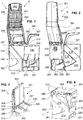
- Fig. 1
- shows a perspective front side view of an embodiment of the convertible airplane seat according to the invention in a seat configuration;
- Fig. 2
- shows a perspective backside view of the airplane seat according to
Fig. 1 ; - Fig. 3
- shows a detail of
Fig. 1 with a partly folded-in backrest; - Fig. 4
- shows in a perspective view the airplane seat according to
Fig. 1 with a collapsed backrest; - Fig. 5
- shows the airplane seat according to
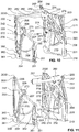
Fig. 4 from a different viewing angle; - Fig. 6
- shows a detail of
Figs. 4 and5 ; - Fig. 7
- shows a suitcase shell of the airplane seat according to the previous figures with a closed cover plate;
- Fig. 8
- shows the suitcase shell from another viewing angle;
- Fig. 9
- shows the suitcase shell according to
Fig. 7 without the cover plate, wherein a lateral plate is visible; - Fig. 10
- shows a seat frame of the airplane seat according to
Figs. 1 to 6 with the lateral plate according toFig. 9 in the seat position; - Fig. 11
- shows the seat frame according to
Fig. 10 with the lateral plate in the suitcase position; - Fig. 12
- shows the seat frame according to
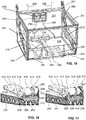
Fig. 10 including the suitcase shell according toFigs. 7 to 9 and a foot traverse connecting from front legs of the airplane seat; - Fig. 13
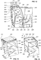
- shows the airplane seat according to the invention in a seat configuration with a completely collapsed backrest;
- Fig. 14
- shows the airplane seat according to
Fig. 13 , wherein the suitcase shell and the backrest are rotated by 90 degrees such as to bring the airplane seat according to invention into the displayed, suitcase configuration which is more compact with respect the seat configuration; - Fig. 15
- shows the activation mechanism for collapsing the backrest and rotating to suitcase shell;
- Fig. 16
- shows a detail of the backrest movement mechanism in disengaged collapsed position;
- Fig. 17
- shows a detail of the backrest movement mechanism in engaged collapsed position;
- Fig. 18
- shows the foot traverse connecting the front legs according to
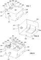
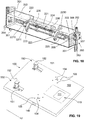
Fig. 5 and further figures in detail; - Fig. 19
- shows an adapter plate that may be integrated into an airplane for receiving and securing the airplane seat according to the invention including wheel retainer, latch slots and a foot board;
- Fig. 20
- the adapter plate according to
Fig. 19 with removed top floor plate for revealing interior details of the adapter plate including two wheel retainer elements, a foot board assembly, latch catcher boxes, and a central locking arrangement; - Fig. 21
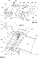
- shows in a perspective view the foot board alone;
- Fig. 22
- shows that foot board assembly in more detail;
- Fig. 23
- shows the working principle of the foot board mechanism;
- Fig. 24
- shows the latch catcher box without latch;
- Fig. 25
- shows the latch catcher box with secured latch;
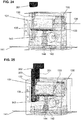
- Fig. 26
- shows the wheel retainer elements in engagement with wheels of the airplane seat according to invention; and
- Fig. 27
- shows a detail of
Fig. 26 . - A preferred embodiment of the
airplane seat 1 according to the present invention is now described with reference to theFigs. 1 to 18 . A preferred embodiment of anadapter plate 100 according to the present invention is described below with reference to theFigs. 19 to 27 . The present invention also relates to aseating system 10 including oneseat 1 and oneplate 100. -
Figures 1 and 2 show a preferred embodiment of theairplane seat 1 according to invention in a seat configuration.Figure 14 shows theairplane seat 1 in the suitcase configuration.Figures 4 ,13 show theairplane seat 1 in an intermediate configuration (collapsedbackrest 300, suitcase shell in seat position). - The
airplane seat 1 comprises aseat frame 200 with thereto laterally attached swivelingarmrests 340. InFigs. 1 and 2 , thearmrests 340 are shown in a folded-out or extended arrangement, inFig. 14 , in a folded away or folded-in or -down arrangement. Furthermore, theseat frame 200 comprises asuitcase shell 240 that is arranged in saidseat frame 200, between thearmrests 340. Thesuitcase shell 240 can be swivelled by 90 degrees into the clockwise direction with respect to the seat configuration A as shown inFigs. 1 and 2 into a suitcase configuration B as shownFig. 14 . Moreover, theairplane seat 1 comprises acollapsible backrest 300.Figures 1 and 2 show thebackrest 300 in the extended or folded-out configuration, whileFig. 14 shows saidbackrest 300 in the collapsed configuration. -
Figure 3 shows a detail ofFigs. 1 and 2 , more precisely thebackrest 300 in a semi-collapsed configuration.Figures 4 and5 show thebackrest 300 in fully collapsed configuration, whilst thesuitcase shell 240 is still oriented in the seat position.Figure 14 shows thebackrest 340 in the completely collapsed configuration, whilst thesuitcase shell 240 is rotated into the suitcase position. - From
Figs. 1 to 5 and14 it is apparent, that thebackrest 300 comprises atop section 301 with anintegrated head section 302 and abottom section 304. Thehead section 302 is a recessed top region of thetop section 301 that provides support to the seated passenger's head. Thetop section 301 and thebottom section 304 are linked together in a pivotable manner relative to one another by means ofmiddle linkage 303. Thetop section 301 may be folded inwardly, i.e. toward theseating surface 231 of theairplane seat 1, onto the front surface of thebottom section 304 of thebackrest 300. Themiddle linkage 303 may be designed such that the folded-out configuration is releasably locked in the seat configuration for ensuring a safe flight. - At the bottom of the
backrest 300, a further linkage with two laterally positionedspline shafts 310 is arranged for pivoting thebottom section 304 of the backrest 300 (including thetop section 301 attached thereto) from the seat position as shown inFigs. 1 and 2 into the collapsed position as shown inFigs. 4 ,5 and14 and back. - In the following, the bottom linkage of the
backrest 300 comprising twospline shafts 310 is described in more detail with reference toFigures 6 ,16 and 17. Figure 16 and 17 show one of thespline shafts 310 in engagement position and in disengagement position, respectively. Also,Fig. 6 shows thespline shafts 310 in disengagement positions. With thespline shafts 310 in engagement position, thebackrest 300 is locked; no rotation is possible. The two locking positions are the extended position as shown inFigs. 1 and 2 and the fully collapsed position as shown, for example, inFigures 13 and 14 . Intermediate locking positions or a continuous locking position may be realized. To rotate thebottom segment 303, thespline shaft 310 should be moved from the engagement position (Fig. 16 ) into the disengagement position (Fig. 17 ). - Each
spline shaft 310 comprises afirst end section 311, a finnedintermediate section 312, and asecond end section 313. Thefirst end section 311 has twoarms 3110 with free ends, wherein thearms 3110 comprise holes for receiving a transversal pin. Thefirst end section 311 has a smaller diameter than the rest of thespline shaft 310 and is received in a through hole of asuitcase shell hub 318. Thesuitcase shell hub 318 is L-shaped and attached to thelateral plate 251 integrated into thesuitcase shell 240. Thespline shafts 310 are arranged in said respectivesuitcase shell hubs 318 in a translatable manner such that they may travel into disengagement position or into engagement position. On the other side of thesuitcase shell hub 318, the finnedintermediate section 312 is extending towards thelateral plate 251. Theintermediate section 312 has an increased diameter with respect to thefirst end section 311. Opposite thefirst end section 311, thesecond end 313 is arranged, which has an even more increase diameter and has, on its front face, a plurality ofaxial segment teeth 314. - The
axial segment teeth 314 are arranged and positioned such that they may engage into theaxial segment teeth 256 of the lockingmember 254 arranged on thelateral plate 251. The size and arrangement of thesegment teeth Figs. 16 and 17 , if thespine spline shaft 310 is in the engagement position (Fig. 16 ), thesegment teeth 314 of thespline shaft 310 and tosegment teeth 256 of thelateral plate 251 are in engagement, whereby thespline shaft 310 is rotatably fixed to the respectivelateral plate 251. Upon moving thespline shaft 310 into the disengagement position (Fig. 17 ), thesegment teeth 314 of thespline shaft 310 and thesegment teeth 256 of thelateral plate 251 are disengaged; accordingly, a rotation of thebottom segment 303 between the extended and collapsed position is possible. - Moreover, between the
suitcase shell hub 318 and thesecond end section 313, there is arranged thespline shaft hub 315 with thetoothed bushing 316. Thetoothed bushing 316, and thereby thespline shaft hub 315, is locked to the finnedintermediate section 312 by a positive fit with thespline shaft 310 with respect to rotation about thespline shaft 310. Moreover, on the other side of thesuitcase shell hub 318 there is arranged thebackrest hub 317 which further guides thefirst end section 311 and connects thebackrest 300 to thespline shaft 310. Thespline shaft 310 may therefore translate along its axis of rotation through thebackrest hub 317, thesuitcase shell hub 318 and thetoothed bushing 316. Thespine shaft 315 and therespective backrest hub 317 are connected to one another by means of screws; the twohubs backrest 300. - Moreover,
Fig. 6 shows a mechanical connection between the twospline shafts 310 that rotatably locks the twoshafts 310 while allowing a movement toward and away from one another along the longitudinal direction of theshafts 310. - This mechanical connection comprises first and second connecting
rods respective arms 3110 of the respectivefirst end section 311 of thespline shaft 310, respectively. The first and second connectingrods spline shafts 310. The first and second connectingrods dislocation linkage 323 that is arranged in said middle region as shown inFig. 6 . The first and second connectingrods dislocation linkage 323 by means of pins. Moreover, the first and second connectingrods respective arms 3110 by means of anotherpin 324. Thesepins 324 extend on both sides beyond the first and second connectingrods swivel point rod 319. Both swivel pointrods 319 are provided, at their free ends, with aslot 3190 for receiving therespective pin 324. Theswivel point rods 319 also are connected to the H-shapeddislocation linkage 323 by means of a pin as shown inFig. 6 . This mechanical connection between the twospline shafts 310 ensures a synchronous rotation and allows translation of the twospline shafts 310 and thereby allows for a simultaneous engagement/disengagement of thespline shafts 310 from therespective L plate 251. - As can be seen from the figures, the
backrest 300 is generally ergonomically formed. Particularly, thetop section 301 and thebottom section 304 may be somewhat inclined with respect to one another and, in particular, thebottom section 304 may be providing side support to the seated passenger in the lower back region. Moreover, thebackrest 300 width (lateral direction) is tapering towards the top. It is, however, to be understood that the shape of thebackrest 300 may have any desired shape. -
Figures 7 to 9 show thesuitcase shell 240 in more detail. Thesuitcase shell 240 is a case or container with an access opening 244 for receiving luggage into an interior stowing space of thesuitcase shell 240. Theshell 240 may be a single piece element with, as seen in seat position, abottom wall 245, twolateral walls 246, afront wall 248 with a roundedlower section 249, aback wall 247. - Moreover, a
cover plate 230 is provided for covering theaccess opening 244. Saidcover plate 230 is attached to thesuitcase shell 240 in a pivotable manner and may be opened for access to the interior space of thesuitcase shell 240. Moreover, thecover plate 230 provides, with its exterior surface, theseating surface 231 of theairplane seat 1. Theseating surface 231 may also be ergonomically shaped and/or cushioned (not shown). In thecover plate 230, there is integrated abuckle box 242 for receiving the passenger's security belt including the buckle (not shown). - The interior space of the
suitcase shell 240 may have a volume of about 0.01 to 0.1 cubic meters, preferably, of 0.025 to 0.075 cubic meters, depending on the exact geometry of thesuitcase shell 240. - In the middle of each
lateral wall 246 is arranged arotation shaft 241 for engaging thesuitcase shell 240 to theseat frame 200 in a rotatable manner. As can be seen from theFigs. 7 to 9 , therotation shaft 241 projects beyond the respectivelateral wall 246 and, on the outside, comprises a terminal flange for attachment to the shaft mounting 209 of theseat frame 200. -
Figure 9 shows the interior space of thesuitcase shell 240. On the inside of eachlateral wall 246 is arranged alateral plate 251. Thelateral plate 251 is fixedly attached to the respectivelateral wall 246. Thelateral plate 251 has a substantially triangular shape, wherein a hypotenuse runs diagonally across thelateral wall 246 as shown inFig. 9 . The longer leg of each of said triangular shapedlateral plates 251 runs along the respective top edge of thesuitcase shell 240 in seat position. The shorter leg runs along the lateral edge of thefront wall 248 of theshell 240. To minimize the overall weight of theseat 1, thelateral plate 251 comprises amain recess 252 and several smaller throughholes 253 through its legs and hypotenuse. Each of thelateral plates 251 comprises, at its back corner, said lockingmember 254 consisting of a circular disk with a throughhole 257 for receiving therespective spline shaft 310 and of thesegmented teeth 256 encircling the throughhole 257 and arranged on said disk for engagement with theteeth 314 of therespective spline shaft 310. - The above-mentioned security belt is attached to the
lateral plate 251 by means of abelt fastening member 262 as shown inFig. 9 . - Moreover, in the back region in
Fig. 7 , there is shown ashell traverse 260, which connects the twolateral plates 251 with one another. Theshell traverse 260 comprises acentral recess 261 for guiding through a telescopic handle 297 (seeFig. 15 ). Moreover, it comprises twofurther recesses 263 for passage of securingwires 298, see below. - The
seat frame 200 comprises several cover shells 210 (see, for example,Figs. 1 to 5 ) to dress and protect the mechanics integrated intoseat frame 200. The cover protects the user from injury when operating theairplane seat 1 and improves the overall impression of theairplane seat 1. -
Figures 10 to 12 show theseat frame 200 in more detail whilst leaving away some of its parts including some of thecover shells 210. - The
seat frame 200 comprises twofront legs 201 and twoback legs 203. In thefront legs 201 are providedlatch chambers 202 in each of which a verticallymovable latch 351 is arranged. Thelatch 351 is translating upon actuation along the longitudinal direction of the respectivefront leg 201 as will be described in more detail with reference toFig. 18 below. - The
back legs 203 have, at their upper ends, aslot 2030 that is surrounded in its lower part by anabutment element 2031 for receiving and securing thearmrests 340, see below. - The back and
front legs diagonal strut 206 and a top frontdiagonal strut 207 connect the respective back andfront legs front legs diagonal struts rotation shaft 241 of thesuitcase shell 240 is arranged. Moreover, a bottom backdiagonal strut 205 extends from a lower section of the respectiveback leg 203 to the shaft mounting 209. In addition, the top section of thefront legs 201 is connected to the bottom of the respectiveback leg 203 by means of a curvedpin track strut 208. At respective ends of the curvedpin track strut 208 are arranged a front hole 294 (seeFig. 10 ) and a back hole 295 (seeFig. 11 ). These front andback holes suitcase shell 240 and may accommodate the securingpin 292 attached to the respectivelateral wall 246. - The
rotation shaft 241 of thesuitcase shell 240 is received in the shaft mounting 209 such that the flange of theshaft 241 abuts on the outside of the shaft mounting 209. On the inside section, relative to theseat frame 200, agas strut lever 273 is arranged. Thegas strut lever 273 is rotationally fixed to the frame 200 (accordingly, it does not rotate with the shell 240) and has an arm with a free end, at which a second end of thegas strut 270 is rotatably attached. - The
gas strut 270 comprises afirst end 271 and thesecond end 272, wherein thefirst end 271 is attached by means of apin 274 to the arm of thegas strut lever 273 while thesecond end 272 is rotatably attached by means of afurther pin 274 to a middle region of the short leg of the respectivelateral plate 251. Thegas strut 270 helps the passenger to find the seat position of thesuitcase shell 240 as shown inFig. 13 and the suitcase position of thesuitcase shell 240 as shown inFig. 14 when rotation theshell 240. Preferably, thegas strut 270 is arranged such that it reaches its compressed configuration close to a middle region of the rotation path between the seat position and the suitcase position of thesuitcase shell 240. Thereby, the passenger has to manually rotate thesuitcase shell 240 until thegas strut 270 reaches its compressed configuration, whereupon thegas strut 270 takes over and pushes thesuitcase shell 240 into its designated position. -
Figure 10 shows theseat frame 200 with onelateral plate 251 in the seat position. The recess 293 (into which aretractable securing pin 292 is inserted, see below and in particularFig. 15 ) is aligned with the front hole 294 (indicated inFig. 11 ). Thelateral plates 251 may be rotatably fixed in the seat positon or the suitcase position to theseat frame 200 in that the securingpins 292 fixedly attached to the respectivelateral plates 251 extend into thefront hole 294 and theback hole 295 into theseat frame 200, respectively. - At the bottom end of each of the
back legs 203 is arranged awheel house 360 into which awheel 361 is fitted. Thewheel 361 is rotatably accommodated in saidwheel house 360 by means of anaxle 362. As can be seen from theFigs. 10 and 11 , thewheel house 360 is formed by two substantially tear-shaped plates that are attached to the respectiveback leg 203. Coverelements 210 are applied. The sharp end of the tear-shapedwheel house 360 is directed backwards and theaxle 362 and thewheel 361 are arranged such that thewheel 361 is protruding out of thewheel house 360 over the entire back corner region. This ensures that theairplane seat 1 in the suitcase configuration B may be conveniently rolled or towed in an inclined orientation by pushing or pulling it by means of the extendedtelescopic handle 297. - The comparison between
Figs. 10 and 11 shows the plurality of appropriately shapedcover shells 210 that are used to dress the above described seat frame parts. -
Figure 15 shows the activation mechanism for enabling a conversion from the seat configuration A to the suitcase configuration B and back. In theback wall 247, there is arranged aninterlock handle box 281, which accommodates aninterlock handle 280. The interlock handle 280 may be shifted in saidbox 281 for activatingBowden cables 290. TheBowden cables 290 extend to a securingpin housing 291 arranged on each of thelateral plates 251, at the corner region between the hypotenuse and the short leg of the substantially triangularlateral plates 251. The securingpin housing 291 is fixedly attached to the respectivelateral plate 251. The securingpin housings 291 accommodate anextendable securing pin 292 which, in extended position, may extend into a front orback hole seat frame 200 for securing thelateral plate 251, and thereby thesuitcase shell 240, in the seat position and the suitcase position, respectively. Upon activation of therespective Bowden cable 290, therespective securing pin 291 is retracted, preferably against a return spring member, from the extended engagement position into a disengagement position such that thesuitcase shell 240 may be rotated between the seat position and the suitcase position. Said spring member may bring the securingpin 292 back to its default extended position. - The
spline shafts 310 may be shifted between engagement and disengagement position as shown inFigs. 16 and 17 , respectively, by hand. In a preferred embodiment, thespline shafts 310 are hollow shafts and an actuation or push element, preferably made from plastics, is inserted from the outside through theopening 257 into the central hollow space of therespective spline shaft 310 and fixedly connected therein. The actuation element protrudes out of the 257 opening in the engagement position according toFig. 16 . The passenger may manually push-in the actuation into theopening 257, whereby therespective spline shaft 310 is shifted out of the engagement position (Fig. 16 ) and into the disengagement position according toFig. 17 . Preferably, a return spring member is arranged between any one of thehubs 315 to 318 and therespective spline shaft 310 such that saidspline shaft 310 is automatically pushed into the engagement position according toFig. 16 . The passenger pushing the actuation element through the 257 opening for effecting a manually driven rotation of thebackrest 300 has to work against said return spring member. - Furthermore, securing
wires 298 are fastened infastening recess 325 in eachbackrest hub 317. The securingwires 298 are substantially stiff elements that are guided throughrecesses 263 in the shell traverse 260 into the interlockinghandle box 281. If thebackrest 300 and thespline shafts 310 are in extended position as seen, for example, inFigs. 1 and 2 , the securingwires 298 engage into the interlockinghandle box 281 such as to block the interlocking handle 280 from actuating theBowden cables 290. This avoids that rear passengers accidentally activate the interlocking handle 280 while theairplane seat 1 is installed for travel. If thebackrest 300 and thespline shafts 310 are in collapsed position as seen, for example, inFig. 4 , the securingwires 298 no longer block the translation motion of the interlocking handle 280 such that the interlockinghandle 280 may be activated to disengage thesuitcase shell 240 for rotation into the suitcase position as seen inFig. 14 . - The
Bowden cables 290 may generally act against return spring elements that bring the actuated element back to its original position. - Moreover,
Fig. 15 shows an embodiment of thetelescopic handle 297 attached to theback wall 247 by means of telescopichandle mounting elements 296.Figure 15 shows a T-shaped handle in its collapsed configuration, of course a differently shaped handle may be deployed.Figure 14 shows an appropriately shaped recess in thebottom wall 245 for receiving a gripping portion of thetelescopic handle 297. The recess for the gripping portion of thetelescopic handle 297 is covered by thecover 243. Thecover 243 comprises an opening for passage of the telescope arm of thetelescopic handle 297. - The
armrests 340 are generally L-shaped comprising afirst armrest portion 342 and asecond armrest portion 343 attached to saidfirst armrest portion 342. Each free end of thefirst armrest portion 342 is attached to theseat frame 200 in the region of therespective spline shaft 310. For attaching thearmrests 340 theseat frame 200, thefirst armrest portion 342 has a throughslot 3420 at its free end, wherein apin 344 is arranged inside thefirst portion 342, extending transversely and through saidslot 3420. Theseat frame 200 has at the top ends of theback legs 203 vertical slots 2030 (cf.Figs. 10 and 11 ). Around its lower circumference, saidslot 2030 is encircled by a half-ring likeabutment element 2031 that is arranged offset to saidslot 2030 thereby creating a step for receiving the free end of the first armrest portion 342 (cf.Fig. 10 and 11 ) whilst thepin 344 engages into saidslot 2030. Accordingly, theseat frame 200 and eacharmrest 340 are attached to one another in a hinged manner in that saidpin 344 is inserted into saidslot 2030. - If the
pin 344 is positioned at a bottom end of theslot 2030, the free end portion of thefirst armrest portion 342 is received in saidabutment element 2031 in a form fit manner, whereby the armrest is secured in a folded-out position as shown, for example, in theFigs. 1 and 2 ; it may not be rotated in this position. - If the
armrest 340 is pulled upwards, thepin 344 translates upward in saidslot 2030 and, when the free end of thefirst armrest portion 342 has left theabutment element 2031 and is therefore free for rotation, thearmrest 340 may be rotated down as shown, for example, inFig. 5 . Accordingly, thearmrests 340 may be simply folded away by pulling them up and then rotating them down and vice versa. -
Figure 18 shows the foot traverse 220 with the latch movement mechanism for anchoring thefront legs 201 in anadaptor plate 100. Theadaptor plate 100 may be integrated into a floor of a vessel, particularly into the floor of an airplane. - The
foot traverse 220 is basically a box-shaped hollow element with a rectangular cross-section that connects the bottom sections of thefront legs 201. In a front face of thefoot traverse 220 is arranged a swivelingflap 221 that may be pushed into thefoot traverse 220. As can be seen inFig. 18 , theflap 221 is arranged with its bottom edge to thefoot traverse 220. Theflap 220 is attached by means of aflap shaft 224 which is fastened to theflap 220 and extends along the longitudinal direction of thefoot traverse 220. Theflap shaft 224 protrudes beyond theflap 221 and is rotatably fixed with its protruding portions by means of flapshaft mounting elements 225 to the inner surface of the front face of thefoot traverse 220. - The
flap 221 is a substantially plate-like element, wherein its lateral end portions are bent by 90 degrees to extend transversely to the front face of the foot traverse 220 such as to formwings 2210 on either side of theflap 221. Thewings 2210 taper towards theflap shaft 224 and are each provided with ahole 2211. Aflap cable 222 is secured in eachhole 2211. Eachflap cable 222 is then guided to aflap cable guide 223 which is arranged in thefoot traverse 220, close to the flapshaft mounting elements 225 as shown inFig. 18 . Theflap cable guide 223 comprises a throughopening 2230 arranged close to the front face of thefoot traverse 220. Eachflap cable 222 is guided through the respective throughhole 2230 and extends to and through the respectivelateral face 227 into the bottom part of thefront leg 201, where alatch holder 355 of a latch fitting 350 is fixedly attached to thefront leg 201. Thelatch holder 355 is arranged in the lower part of thelatch chamber 202. - As can be seen from
Fig. 18 , thelatch cable 222 is guided through thelatch holder 355 via acable guide 357 and then guided upwards to be attached to an upper part of a rod-like latch body 352. Thelatch body 352 extends vertically through thelatch holder 355 and may be shifted therethrough.Figure 18 shows thelatch body 352 in its lowest position, the lowest position being defined by atransverse pin 356 in thelatch body 352, wherein thetransverse pin 356 abuts against an appropriately shaped top surface oflatch holder 355. - Moreover, the
latch body 352 is provided at its lower end with alatch 351 with acentral opening 353. In the extended or bottom position as shown inFig. 18 , thelatch 351 protrudes out of thelatch chamber 202 downward beyond theleg 201 for engagement with theadapter plate 100. The latch mechanism may be provided with a return spring member arranged in thechamber 202, the spring member pulling the releasedlatch body 352 out of the bottom position as shown inFig.18 into a retracted upward position. Upon pushing theflap 220 into thefoot traverse 220, as shown inFig. 18 , eachflap cable 222 is pulled through the cable guides 2230 and 357, whereby thelatch body 352 is pulled, against the spring and under guidance of thelatch holder 355, down into its extended position where thetransverse pin 356 stops against thelatch holder 355 such that thelatch 351 protrudes beyond theleg 201. - A preferred embodiment of the
adapter plate 100 according to invention is explained with reference to theFigures 19 to 27 . -
Figure 19 shows in a perspective top view theadapter plate 100 comprising atop floor plate 102. A wheel retainer assembly comprises twowheel retainers 150 provided in saidadapter plate 100. Eachwheel retainer 150 comprises a swiveling, hook-like retainer element 152 which is shown in an extended position and which may be rotated into arecess 151 in theplate 100. Thewheel retainer elements 152 are used engage theairplane seat 1 with theadapter plate 100. - The hook-like shape allows to accommodated the
wheels 361 without extra-loading thewheels 361. The hook-like retainer elements 152 directly contact thewheel housing 360, on the horizontal top surface just above the axle 363. - The
adapter plate 100 comprises twolatch slots 104 into which the latch is 351 may be inserted for securing theairplane seat 1 to theadapter plate 100 when thewheels 361 are received in thewheel retainers 150. - Moreover, in the right part of
Fig. 19 , afoot board assembly 110 with afoot board 111 is shown. Thefoot board 111 is partly accessible from the outside and movable along theadapter plate 100 for each folding-out thewheel retainers 150 and for releasing anylatch 351 inserted intolatch slot 104. Moreover,several screw holes 105 are visible for connecting mounting plates 106 (seeFigs. 20 and23 ) with thetop floor plate 101. - The arrow F indicates the typical direction of travel of the
adapter plate 100. -
Figure 20 shows the subject-matter ofFig. 19 , while thetop plate 102 is removed to reveal thefloor plate core 101.Figure 20 shows abottom floor plate 102 on which, on the left inFig. 20 ,base elements 155 are arranged. Thebase elements 155 are provided with therecesses 151 for accommodating thewheel retainer elements 152 which creates a flush top surface of theplate 100 if theelements 152 folded-in. - The swiveling
retainer elements 152 for catching thewheel housing 360 are L-shaped with a short, deflectedportion 153 and a long portion. Thebase elements 155 comprise mountinggrooves 156 for receiving a shaft (not shown) attached to a free end of said long portion of theretainer element 152, whereby thewheel retainer elements 152 are rotatably arranged in saidadaptor plate 100 and may be rotated in and out of therecesses 151. Accordingly, thewheel retainer elements 152 may be rotated between an extended position as seen inFigs. 19 and26 and a retracted position (not shown) in which theretainer elements 152 are accommodated in therespective recesses 151 such that the top surface of theadapter plate 100 is substantially flush. -
Figures 26 and 27 show thewheel retainer elements 152 in more detail. The deflectedportion 153 of the extendedwheel retainer element 152 engages the back and top surface of thewheel housing 360 and thereby secures theairplane seat 1 to theadapter plate 100. The rotation of thewheel retainer elements 152 is effected by respectivewheel retainer cables 154 which are attached to arespective mounting disk 157 arranged on theelements 152. The mountingdisk 157 is a substantially quarter-ring shaped disk with agroove 1570 on its circumferential curved face for receiving thecable 154. At the lower region of the mountingdisk 157, at the end of thatgroove 1570, there is arranged apart cylindrical recess 1571. The end of thewheel retainer cable 154 may be engaged to a cylinder element which is inserted in saidpart cylindrical recess 1571 for securing the cable to the mountingdisk 157. Moreover, there is a return spring element (not shown) arranged in operative connection with the respectivewheel retainer elements 152 such as to put to thewheel retainer elements 152 into the retracted position. Upon applying a pulling force to thewheel retainer cables 154, the mountingdisks 157, and thewheel retainer elements 152 fixedly attached thereto, rotate around the wheel retainer shaft (not shown) into the extended position as shown, for example, inFig. 26 . -
Figure 22 shows thefoot board assembly 110 including thefoot board 111 according toFigure 21 in more detail. Thefoot board assembly 110 comprises saidfoot board 111 which is arranged in afoot board box 115 that has twolateral walls 116 and abox frame 1150. Thefoot board 111 is guided between thelateral walls 116. As can be seen fromFig. 21 , thefoot board 111 is of a rectangular shape and has, in the region of one of its narrow edges, a step which is realized by a rounded deflectedsection 112, whereby an offsetfoot section 113 is created that is substantially parallel to a main section of thefoot board 111. Moreover, thefoot section 113 is provided with twocurved slots 114 as shown inFig. 21 . -
Figure 22 andFigure 23 show, on the left side when facing into the direction of travel F, a two-lever arm 117 rotatably arranged on avertical pin 118. InFig. 23 , some elements have been removed for clarity. The two-arm lever 117 has a short arm which is oriented along the direction of travel inFig. 22 and a long arm which is arranged at right angles to said short arm. The short and the long arm are fixed relative to one another and may rotate about the pin 18. Both arms compriseslots 120 along their respective lengthwise direction. As can be seen fromFig. 23 , the two-lever arms 117 comprise a plurality of plate-like elements. These plate-like elements are attached to one another by means ofpin 118 andfurther pins 119, thepins 119 being attached at the free ends of the long and short arms of each of the two-arm levers 117. InFig. 20 the right two-arm lever 117 is partly removed such as to reveal that theterminal pins 119 inserted into the long arms are engaging into and guided by the respectivecurved slots 114 on thefoot board 111. The terminal pins 119 in the short arms travel freely. - A
slot stone 121 is arranged between the two top most plate-like elements of each of the two-arm levers 117. Theslot stones 121 may be moved along therespective slot 120 of the respective arm of the two-arm levers 117. Eachwheel retainer cable 154 is attached to therespective slot stone 121 in the long arm of the two-arm lever 117, whilebolt cables 134 are attached torespective slot stones 121 guided in the short arm of the two-arm levers 117. The movability of theslot stones 121 ensures that the respective attachedcables arm lever 117. - The
foot board 111 may be shifted from the positon as shown in theFigs. 22 and23 such that the two-arm levers 117 connected to thefoot board 111 viapins 119 in the long arms of 117 are rotated against each other. This rotation of thelevers 117 pulls thecables foot board box 115, thereby bringing thewheel retainer elements 152 against a return spring element (not shown) from the collapsed position into the extended position as shown, for example, inFig. 26 and bringing the latch bolt 131 (seeFigs. 24, 25 ) against a return spring element (not shown) from a locking position (Fig. 25 ) into a release position such that thelatches 351 are released and may be pulled out of thelatch slots 104. - Upon
foot board 111 activated rotation of thelevers 117, thepins 119 travel in thecurved slots 114. - A top surface of the
foot board 111 may be provided with an anti-slip coating and/or structure such that the passenger easily finds grip thereon with his foot for moving thefoot plate 111 horizontally in saidfoot board box 115 for activating thewheel retainers 150 or for releasing thelatches 351 engaged inlatch slots 104. - Next, the latch catching mechanism is explained with reference to
Figures 24 and 25 . The latch catching mechanism is a mechanism that locks thefront legs 201 to theadapter plate 100. Below each latch slot 104 (seeFig. 19 ) is arranged a latch catcher box 130 (seeFig. 20 ). Thelatch catcher box 130 is a housing with a horizontallatch bolt guide 133 in which alatch bolt 131 may translate in a direction parallel to a top surface of theadaptor plate 100. Thelatch catcher box 130 is mounted into theadapter plate 100 by means of mountingplates 106. A front end of thelatch bolt 131, designed for engagement with thelatch 351, has an inclined surface (with respect to the motion direction of the latch 351). A back end of thelatch bolt 131 is engaged to thebolt cable 134 which is pulled back against the return spring element upon rotation of the two-arm lever 117. - A feeler may be integrated into a
recess 135 for providing information about the latch locking state to a central information system, e.g. to inform the crew or pilot about the locking state of theseats 1 aboard the airplane. - Accordingly, the passenger may move his
seat 1 onto theadapter plate 100 withcollapsed wheel retainers 150, whereupon the passenger may step on thefoot board 111 to shift thefoot board 111 in the flight direction. This causes thewheel retainers 150 to fold up against the return spring element. The passenger may push the wheel houses 360 into theretainers 152 and may release thefoot board 111 and put theseat 1 down. Thereafter, the passenger may push theflap 221, whereupon thelatches 351 are pushed against the return spring element into theslots 104. Due to theinclined surfaces 132, thelatches 351 automatically push back thelatch bolts 131 against the respective return spring elements. Once thelatches 351 are in fully extended position, thelatch bolts 131 may snap-back intolatch openings 352 due to the return spring element, whereby thelatches 351 are locked and theseat 1 is properly secured to theadaptor plate 100. Thebackrest 300 may be extended as described above. - Moreover, the
adaptor plate 100 provides elements for a central locking system which may be activated, in case of an airplane, by the pilot or crew before take-off and after the electronic system including the feeler signals proper locking state. The central locking ensures that noseat 1 is manipulated during flight. - The central locking system comprises a
central locking housing 140 which accommodates a return spring member and acentral locking cable 141 attached to said spring member. Thecentral locking housing 140 is preferably attached to theadapter plate 100 by means of mountingplates 106. Thecentral locking cable 141 extends from thehousing 140 below the latch bolts 131 (seeFigs. 23 to 25 ) to an activation unit which pulls thecentral locking cable 141 upon command (e.g. from the pilot) against the spring member. Between thecentral locking cable 141 and thelatch bolt 131 is arranged a movablecentral locking pin 143. Thelocking pin 143 has, at is lower section, a block with aninclined surface 144. On thecentral locking cable 141, close to theinclined surface 144, is arranged acentral locking trigger 142. If the central locking system is open, as inFigs. 24, 25 , thecentral locking pin 143 is arranged spaced to thelatch bolt 131 in engagement position. Upon pulling thecentral locking cable 141, thecentral locking trigger 142 travels to engage and push upwards theinclined surface 144, whereupon the central locking pin travels towards thelatch bolt 131 and engages into a hole in thelatch bolt 131. As thecentral locking pin 131 is arranged at right angles to thelatch bolt 131, thelatch bolt 131 may not move freely anymore if thecentral locking pin 143 engages into thelatch bolt 131. Accordingly, thelatch 351 remains locked. - Moreover, as the
latch bolt 131 may not move anymore, the Bowden cable 134 (bolt cable) is also block, which, in turn, blocks thefoot board 111. Accordingly, by blocking thelatch bolts 131 with the central locking system, also thewheel retainer elements 152 that are not extended, i.e. that are in collapsed position, are locked as thefoot board 111 may not be activated to release thewheel retainer elements 152.LIST OF REFERENCE SIGNS 1 airplane seat 134 bolt cable 135 recess for a feeler 100 adapter plate 101 floor plate core 140 central locking housing 102 top floor plate 141 central locking cable 103 bottom floor plate 142 central locking trigger 104 latch slot 143 central locking pin 105 screw hole 144 inclined surface 106 mounting plate 150 wheel retainer 151 recess for 152 110 foot board assembly 152 swiveling retainer element 153 deflected portion 111 foot board 154 wheel retainer cable 112 deflected section 155 base element 113 foot section 156 mounting groove 114 curved slot 157 mounting disc 115 foot board box 1570 groove in 157 1150 box frame 1571 recess at end of 1570 116 lateral wall of 114 200 seat frame 117 two-arm lever 201 front leg 118 pin 202 latch chamber 119 terminal pin 203 back leg 120 lever arm slot 2030 slot for pin of 340 121 slot stone 2031 abutment element 204 bottom horizontal strut 130 latch catcher box 205 bottom back diagonal strut 131 latch bolt 206 top back diagonal strut 132 inclined surface 207 top front diagonal strut 133 bolt guide 208 pin track strut 209 shaft mounting 252 main recess in 251 253 hole in 251 210 cover shell 254 locking member 256 segment tooth of 254 220 foot traverse 257 recess for 310 221 flap 2210 flap wing 2211 hole in 2210 260 shell traverse 222 flap cable 261 recess in 260 for telescopic 223 flap cable guide handle 2230 through opening 262 belt fastening member 224 flap shaft 263 securing wire recess 225 flap shaft mounting element 226 flap mounting 270 gas strut 227 lateral face of 220 271 first end 270 272 second end of 270 230 cover plate 273 gas strut lever 231 seating surface 274 pin 240 swivel suitcase shell 280 interlock handle 241 rotation shaft 281 interlock handle box 242 buckle box 243 cover for telescopic handle ( Fig. 14 )290 Bowden cable 291 securing pin housing 244 access opening ( Fig. 9 )292 securing pin 245 bottom wall of 240 293 reception for 291 246 lateral wall of 240 294 front hole for 292 ( Fig. 11 )247 back wall of 240 295 back hole for 292 ( Fig. 10 )248 front wall of 240 249 rounded wall section of 240 296 telescopic handle mounting 297 telescopic handle 250 shell frame 251 lateral plate 298 securing wire 323 H-shaped dislocation linkage 300 backrest 324 connecting pin 301 top segment of 300 325 fastening recess for 298 302 head rest in 301 303 bottom segment of 300 340 swivel armrest 304 middle linkage of 300 341 armrest hinge 342 first armrest portion 310 spline shaft 3420 slot 311 first end section of 310 343 second armrest portion 3110 arm of 311 344 pin ( Figs. 4 ,6 )312 finned intermediate section 313 second end section 310 350 latch fitting 314 axial segment teeth 351 latch 315 spline shaft hub 352 latch body 316 toothed bushing 353 latch opening 317 backrest hub of 310 355 latch holder 318 suitcase shell hub of 310 356 pin 319 swivel point rod 357 cable guide 3190 slot in 319 interlock handle box 360 wheel fitting/house 320 slot at free end of 319 361 wheel 321 first connecting rod 362 axle of 361 322 second connecting rod
Claims (15)
- A removable passenger seat (1) for an airplane comprising:a seat frame (200);a suitcase shell (240) for stowing luggage, said suitcase shell (240) being arranged in said seat frame (200); anda collapsible backrest (300);characterized in that said suitcase shell (240) is arranged in a swiveling manner such that said seat (1) may be converted from a seat configuration (A) into a suitcase configuration (B) and back by collapsing said backrest (300) and by swiveling said suitcase shell (240) from a seat positon to a suitcase position.
- The seat (1) according to claim 1, wherein said suitcase shell (240) is a rigid shell of a substantially cuboidal shape.
- The seat (1) according to any one of the preceding claims, wherein a volume of the suitcase shell (240) is at least 0.01 cubic meters and is preferably selected from a range of from 0.01 cubic meters to 0.1 cubic meters, preferably 0.025 cubic meters to 0.075 cubic meters.
- The seat (1) according to any one of the preceding claims, wherein said suitcase shell (240) comprises an access opening (244);wherein said suitcase shell (240) is preferably a single piece element; and/orwherein said access opening (244) is covered by means of a cover plate (230); andwherein said cover plate (230) serves as seating surface (231) of said seat (1).
- The seat (1) according to any one of the preceding claims, wherein a swiveling angle of said suitcase shell (240) between said seat configuration (A) and said suitcase configuration (B) is in a range of from 70 to 100 degrees, preferably 90 degrees.
- The seat (1) according to any one of the preceding claims, wherein an axis of rotation of said suitcase shell (240) extends substantially centrally through said suitcase shell (240).
- The seat (1) according to any one of the preceding claims, wherein said backrest (300) comprises two or more sections (301, 304) that are attached to one another in a swiveling manner.
- The seat (1) according to any one of the preceding claims, wherein said seat (1) is configured such that said suitcase shell (240) is releasably lockable in said seat position and in said suitcase position, wherein said seat (1) further comprises an interlocking handle (280) for releasing said suitcase shell (240);wherein said interlocking handle is preferably integrated into a back wall (245) of said suitcase shell (240); and/orwherein said seat (1) preferably comprises a securing element (298) which is arranged and configured such that said interlocking handle (280) is ineffective or blocked if said backrest (300) is in an extended position.
- The seat (1) according to any one of the preceding claims, wherein said seat (1) comprises armrests (340), said armrests (340) being preferably attached to said seat frame (200) in a hinged manner.
- The seat (1) according to any one of the preceding claims, that further comprises a telescopic handle (297), said telescopic handle being preferably attached to a bottom plate (245) of said suitcase shell (240), said bottom plate (245) being arranged opposite said cover plate (230).
- The seat (1) according to any one of the preceding claims, wherein said seat frame comprises front legs (201) and back legs (203), wherein wheels (361) are attached to said back legs (203) such that said seat (1) in said suitcase configuration (B) is a wheeled suitcase.
- The seat (1) according to any one of the preceding claims, wherein a moveable latch (351) is arranged at or in each front leg (201) for attaching said seat to a floor section (100) of an airplane;wherein said latch (351) is preferably extendable from a retracted position such as to protrude downward beyond said respective front leg (201); and/orwherein said seat frame (200) preferably comprises a foot traverse (220) that connects said front legs (201) and that accommodates an actuation element (221), wherein, upon operation of said actuation element (221), said latches (351) are extended.
- The seat (1) according to any one of the preceding claims, wherein said collapsible backrest (300) is attached to said suitcase shell (240), preferably in a hinged manner, wherein said backrest (300) is collapsible onto said suitcase shell (240).
- A seating system (10) comprising a seat (1) according to any one of the claims 1 to 13 and an adaptor plate (100) use in an airplane, the adaptor plate (100) comprising:at least one, preferably two, wheel retainer (150) for retaining a wheel (361) of a seat (1), wherein the wheel retainer (150) preferably comprises a hook-like wheel retainer element (152) for accommodating the wheel (361), wherein, preferably, said wheel retainer element (152) can be rotated from a collapsed position, in which the wheel retainer element (152) is received in a wheel retainer element recess (151) such that a top surface of the adapter plate (100) is substantially planar and continuous, into an extended position, in which said wheel retainer element (152) may receive and accommodate said wheel (361) whilst securing said seat (1), the securing being in particular with regard to forces acting perpendicularly to said top surface of the adaptor plate (100); andat least one latch slot (104) for insertion and locking of latch (351) attached to said seat (1).
- The seating system (10) according to claim 14, wherein the adaptor plate (100) comprises two wheel retainer elements (152) that can be rotated between the extended and the collapsed position, and opposing two latch slots (104), wherein a locking mechanism (130) is associated with each latch slot (104), wherein the adaptor plate (100) preferably further comprises a central locking system (140) by means of which the locking mechanism (130) and/or the wheel retainer elements (152) may be locked one or both collapsed and extended positions.
Priority Applications (1)
| Application Number | Priority Date | Filing Date | Title |
|---|---|---|---|
| EP17173072.4A EP3406523B1 (en) | 2017-05-26 | 2017-05-26 | Seat and adaptor plate therefor |
Applications Claiming Priority (1)
| Application Number | Priority Date | Filing Date | Title |
|---|---|---|---|
| EP17173072.4A EP3406523B1 (en) | 2017-05-26 | 2017-05-26 | Seat and adaptor plate therefor |
Publications (2)
| Publication Number | Publication Date |
|---|---|
| EP3406523A1 true EP3406523A1 (en) | 2018-11-28 |
| EP3406523B1 EP3406523B1 (en) | 2020-11-18 |
Family
ID=58800700
Family Applications (1)
| Application Number | Title | Priority Date | Filing Date |
|---|---|---|---|
| EP17173072.4A Active EP3406523B1 (en) | 2017-05-26 | 2017-05-26 | Seat and adaptor plate therefor |
Country Status (1)
| Country | Link |
|---|---|
| EP (1) | EP3406523B1 (en) |
Citations (11)
| Publication number | Priority date | Publication date | Assignee | Title |
|---|---|---|---|---|
| GB2098935A (en) * | 1981-05-27 | 1982-12-01 | Messerschmitt Boelkow Blohm | Collapsible wheelchair for a disabled person |
| DE29911783U1 (en) * | 1999-07-07 | 2000-11-16 | Johnson Controls Gmbh | Removable vehicle seat |
| US8152101B2 (en) * | 2006-09-12 | 2012-04-10 | Law Sondra F | System and method for integrating handicapped accessible seats into aircraft interior configurations |
| GB2491552A (en) * | 2011-02-28 | 2012-12-12 | Phillip Pain | Multi-purpose apparatus |
| EP2705984A1 (en) | 2012-09-05 | 2014-03-12 | Airbus Operations GmbH | Removable passenger seat element |
| EP2759447A2 (en) | 2013-01-24 | 2014-07-30 | Airbus Operations GmbH | Passenger seat, baggage item and passenger seat/baggage item system |
| US20150008714A1 (en) * | 2011-10-07 | 2015-01-08 | Bombardier Inc. | Aircraft seat |
| US20150075933A1 (en) * | 2012-03-28 | 2015-03-19 | Tamar Clarke | Luggage apparatus |
| US20150145292A1 (en) | 2013-11-27 | 2015-05-28 | B/E Aerospace, Inc. | Carry-on passenger seat |
| EP2965990A1 (en) * | 2014-07-08 | 2016-01-13 | Airbus Operations GmbH | Passenger seat for a means of transportation |
| WO2016012869A1 (en) * | 2014-07-25 | 2016-01-28 | Fowler Magdalena Elizabeth Maria | Small child airliner seat |
-
2017
- 2017-05-26 EP EP17173072.4A patent/EP3406523B1/en active Active
Patent Citations (11)
| Publication number | Priority date | Publication date | Assignee | Title |
|---|---|---|---|---|
| GB2098935A (en) * | 1981-05-27 | 1982-12-01 | Messerschmitt Boelkow Blohm | Collapsible wheelchair for a disabled person |
| DE29911783U1 (en) * | 1999-07-07 | 2000-11-16 | Johnson Controls Gmbh | Removable vehicle seat |
| US8152101B2 (en) * | 2006-09-12 | 2012-04-10 | Law Sondra F | System and method for integrating handicapped accessible seats into aircraft interior configurations |
| GB2491552A (en) * | 2011-02-28 | 2012-12-12 | Phillip Pain | Multi-purpose apparatus |
| US20150008714A1 (en) * | 2011-10-07 | 2015-01-08 | Bombardier Inc. | Aircraft seat |
| US20150075933A1 (en) * | 2012-03-28 | 2015-03-19 | Tamar Clarke | Luggage apparatus |
| EP2705984A1 (en) | 2012-09-05 | 2014-03-12 | Airbus Operations GmbH | Removable passenger seat element |
| EP2759447A2 (en) | 2013-01-24 | 2014-07-30 | Airbus Operations GmbH | Passenger seat, baggage item and passenger seat/baggage item system |
| US20150145292A1 (en) | 2013-11-27 | 2015-05-28 | B/E Aerospace, Inc. | Carry-on passenger seat |
| EP2965990A1 (en) * | 2014-07-08 | 2016-01-13 | Airbus Operations GmbH | Passenger seat for a means of transportation |
| WO2016012869A1 (en) * | 2014-07-25 | 2016-01-28 | Fowler Magdalena Elizabeth Maria | Small child airliner seat |
Also Published As
| Publication number | Publication date |
|---|---|
| EP3406523B1 (en) | 2020-11-18 |
Similar Documents
| Publication | Publication Date | Title |
|---|---|---|
| EP0348014B1 (en) | Suitcase | |
| CN113060208B (en) | Children's barrow device | |
| US7051853B2 (en) | Convertible luggage device | |
| CA2859000C (en) | Vehicle seat | |
| US9102409B2 (en) | Device for retractable tablet and seat | |
| US20180016011A1 (en) | Intermediate Stowage Retainer for Aircraft Monument Storage Bay | |
| US4974870A (en) | Lightweight, compact, erectable/collapsible wheeled seat | |
| US11390383B2 (en) | Stowage and removal system for rollable containers in a vehicle, and a vehicle, in particular a commercial aircraft, with such a system | |
| US10940948B2 (en) | Aircraft seat for cabin crew | |
| US11383839B2 (en) | Reconfigurable narrow galley cart for single-aisle aircraft | |
| EP3188968A1 (en) | Trolley arrangement of a galley of a vehicle, especially of an aircraft | |
| EP3315712B1 (en) | Rotating retractable step system | |
| US11420748B2 (en) | Galley cart extraction and retention system for multiple-cart bays | |
| EP3406523B1 (en) | Seat and adaptor plate therefor | |
| EP2332833B1 (en) | Lockable cable-actuated latching mechanism | |
| WO2015164974A1 (en) | Article of luggage with stowable wheels | |
| US11912186B2 (en) | Modular tray table with rotational displacement mechanism | |
| CN215322797U (en) | Children's barrow |
Legal Events
| Date | Code | Title | Description |
|---|---|---|---|
| PUAI | Public reference made under article 153(3) epc to a published international application that has entered the european phase |
Free format text: ORIGINAL CODE: 0009012 |
|
| STAA | Information on the status of an ep patent application or granted ep patent |
Free format text: STATUS: THE APPLICATION HAS BEEN PUBLISHED |
|
| AK | Designated contracting states |
Kind code of ref document: A1 Designated state(s): AL AT BE BG CH CY CZ DE DK EE ES FI FR GB GR HR HU IE IS IT LI LT LU LV MC MK MT NL NO PL PT RO RS SE SI SK SM TR |
|
| AX | Request for extension of the european patent |
Extension state: BA ME |
|
| STAA | Information on the status of an ep patent application or granted ep patent |
Free format text: STATUS: REQUEST FOR EXAMINATION WAS MADE |
|
| 17P | Request for examination filed |
Effective date: 20190522 |
|
| RBV | Designated contracting states (corrected) |
Designated state(s): AL AT BE BG CH CY CZ DE DK EE ES FI FR GB GR HR HU IE IS IT LI LT LU LV MC MK MT NL NO PL PT RO RS SE SI SK SM TR |
|
| STAA | Information on the status of an ep patent application or granted ep patent |
Free format text: STATUS: EXAMINATION IS IN PROGRESS |
|
| 17Q | First examination report despatched |
Effective date: 20190927 |
|
| RIC1 | Information provided on ipc code assigned before grant |
Ipc: B64D 11/06 20060101AFI20200327BHEP Ipc: B60N 2/015 20060101ALI20200327BHEP |
|
| GRAP | Despatch of communication of intention to grant a patent |
Free format text: ORIGINAL CODE: EPIDOSNIGR1 |
|
| STAA | Information on the status of an ep patent application or granted ep patent |
Free format text: STATUS: GRANT OF PATENT IS INTENDED |
|
| GRAJ | Information related to disapproval of communication of intention to grant by the applicant or resumption of examination proceedings by the epo deleted |
Free format text: ORIGINAL CODE: EPIDOSDIGR1 |
|
| STAA | Information on the status of an ep patent application or granted ep patent |
Free format text: STATUS: EXAMINATION IS IN PROGRESS |
|
| INTG | Intention to grant announced |
Effective date: 20200512 |
|
| GRAP | Despatch of communication of intention to grant a patent |
Free format text: ORIGINAL CODE: EPIDOSNIGR1 |
|
| STAA | Information on the status of an ep patent application or granted ep patent |
Free format text: STATUS: GRANT OF PATENT IS INTENDED |
|
| INTC | Intention to grant announced (deleted) | ||
| RIN1 | Information on inventor provided before grant (corrected) |
Inventor name: GEROLD, MANUEL Inventor name: TESTONII, OLEG Inventor name: PAYSEN-PETERSEN, ROMAN Inventor name: STAUB, THEO Inventor name: ERMANNI, PAOLO Inventor name: WALKER, ANDREAS Inventor name: WUETHRICH, MORITZ Inventor name: HAEUSERMANN, DAVID Inventor name: SCHACHER, BENJAMIN Inventor name: GROSJEAN, VALENTIN Inventor name: EGGLER, THERESA Inventor name: KUENNECKE, ANNINA Inventor name: KARL, CHRISTOPH |
|
| INTG | Intention to grant announced |
Effective date: 20200619 |
|
| GRAS | Grant fee paid |
Free format text: ORIGINAL CODE: EPIDOSNIGR3 |
|
| GRAA | (expected) grant |
Free format text: ORIGINAL CODE: 0009210 |
|
| STAA | Information on the status of an ep patent application or granted ep patent |
Free format text: STATUS: THE PATENT HAS BEEN GRANTED |
|
| AK | Designated contracting states |
Kind code of ref document: B1 Designated state(s): AL AT BE BG CH CY CZ DE DK EE ES FI FR GB GR HR HU IE IS IT LI LT LU LV MC MK MT NL NO PL PT RO RS SE SI SK SM TR |
|
| REG | Reference to a national code |
Ref country code: GB Ref legal event code: FG4D |
|
| REG | Reference to a national code |
Ref country code: CH Ref legal event code: EP |
|
| REG | Reference to a national code |
Ref country code: IE Ref legal event code: FG4D |
|
| REG | Reference to a national code |
Ref country code: DE Ref legal event code: R096 Ref document number: 602017027623 Country of ref document: DE |
|
| REG | Reference to a national code |
Ref country code: AT Ref legal event code: REF Ref document number: 1335498 Country of ref document: AT Kind code of ref document: T Effective date: 20201215 |
|
| REG | Reference to a national code |
Ref country code: AT Ref legal event code: MK05 Ref document number: 1335498 Country of ref document: AT Kind code of ref document: T Effective date: 20201118 |
|
| REG | Reference to a national code |
Ref country code: NL Ref legal event code: MP Effective date: 20201118 |
|
| PG25 | Lapsed in a contracting state [announced via postgrant information from national office to epo] |
Ref country code: NO Free format text: LAPSE BECAUSE OF FAILURE TO SUBMIT A TRANSLATION OF THE DESCRIPTION OR TO PAY THE FEE WITHIN THE PRESCRIBED TIME-LIMIT Effective date: 20210218 Ref country code: RS Free format text: LAPSE BECAUSE OF FAILURE TO SUBMIT A TRANSLATION OF THE DESCRIPTION OR TO PAY THE FEE WITHIN THE PRESCRIBED TIME-LIMIT Effective date: 20201118 Ref country code: PT Free format text: LAPSE BECAUSE OF FAILURE TO SUBMIT A TRANSLATION OF THE DESCRIPTION OR TO PAY THE FEE WITHIN THE PRESCRIBED TIME-LIMIT Effective date: 20210318 Ref country code: FI Free format text: LAPSE BECAUSE OF FAILURE TO SUBMIT A TRANSLATION OF THE DESCRIPTION OR TO PAY THE FEE WITHIN THE PRESCRIBED TIME-LIMIT Effective date: 20201118 Ref country code: GR Free format text: LAPSE BECAUSE OF FAILURE TO SUBMIT A TRANSLATION OF THE DESCRIPTION OR TO PAY THE FEE WITHIN THE PRESCRIBED TIME-LIMIT Effective date: 20210219 |
|
| PG25 | Lapsed in a contracting state [announced via postgrant information from national office to epo] |
Ref country code: SE Free format text: LAPSE BECAUSE OF FAILURE TO SUBMIT A TRANSLATION OF THE DESCRIPTION OR TO PAY THE FEE WITHIN THE PRESCRIBED TIME-LIMIT Effective date: 20201118 Ref country code: PL Free format text: LAPSE BECAUSE OF FAILURE TO SUBMIT A TRANSLATION OF THE DESCRIPTION OR TO PAY THE FEE WITHIN THE PRESCRIBED TIME-LIMIT Effective date: 20201118 Ref country code: LV Free format text: LAPSE BECAUSE OF FAILURE TO SUBMIT A TRANSLATION OF THE DESCRIPTION OR TO PAY THE FEE WITHIN THE PRESCRIBED TIME-LIMIT Effective date: 20201118 Ref country code: IS Free format text: LAPSE BECAUSE OF FAILURE TO SUBMIT A TRANSLATION OF THE DESCRIPTION OR TO PAY THE FEE WITHIN THE PRESCRIBED TIME-LIMIT Effective date: 20210318 Ref country code: BG Free format text: LAPSE BECAUSE OF FAILURE TO SUBMIT A TRANSLATION OF THE DESCRIPTION OR TO PAY THE FEE WITHIN THE PRESCRIBED TIME-LIMIT Effective date: 20210218 Ref country code: AT Free format text: LAPSE BECAUSE OF FAILURE TO SUBMIT A TRANSLATION OF THE DESCRIPTION OR TO PAY THE FEE WITHIN THE PRESCRIBED TIME-LIMIT Effective date: 20201118 |
|
| REG | Reference to a national code |
Ref country code: LT Ref legal event code: MG9D |
|
| PG25 | Lapsed in a contracting state [announced via postgrant information from national office to epo] |
Ref country code: HR Free format text: LAPSE BECAUSE OF FAILURE TO SUBMIT A TRANSLATION OF THE DESCRIPTION OR TO PAY THE FEE WITHIN THE PRESCRIBED TIME-LIMIT Effective date: 20201118 |
|
| PG25 | Lapsed in a contracting state [announced via postgrant information from national office to epo] |
Ref country code: SM Free format text: LAPSE BECAUSE OF FAILURE TO SUBMIT A TRANSLATION OF THE DESCRIPTION OR TO PAY THE FEE WITHIN THE PRESCRIBED TIME-LIMIT Effective date: 20201118 Ref country code: LT Free format text: LAPSE BECAUSE OF FAILURE TO SUBMIT A TRANSLATION OF THE DESCRIPTION OR TO PAY THE FEE WITHIN THE PRESCRIBED TIME-LIMIT Effective date: 20201118 Ref country code: CZ Free format text: LAPSE BECAUSE OF FAILURE TO SUBMIT A TRANSLATION OF THE DESCRIPTION OR TO PAY THE FEE WITHIN THE PRESCRIBED TIME-LIMIT Effective date: 20201118 Ref country code: EE Free format text: LAPSE BECAUSE OF FAILURE TO SUBMIT A TRANSLATION OF THE DESCRIPTION OR TO PAY THE FEE WITHIN THE PRESCRIBED TIME-LIMIT Effective date: 20201118 Ref country code: SK Free format text: LAPSE BECAUSE OF FAILURE TO SUBMIT A TRANSLATION OF THE DESCRIPTION OR TO PAY THE FEE WITHIN THE PRESCRIBED TIME-LIMIT Effective date: 20201118 Ref country code: RO Free format text: LAPSE BECAUSE OF FAILURE TO SUBMIT A TRANSLATION OF THE DESCRIPTION OR TO PAY THE FEE WITHIN THE PRESCRIBED TIME-LIMIT Effective date: 20201118 |
|
| REG | Reference to a national code |
Ref country code: DE Ref legal event code: R097 Ref document number: 602017027623 Country of ref document: DE |
|
| PG25 | Lapsed in a contracting state [announced via postgrant information from national office to epo] |
Ref country code: DK Free format text: LAPSE BECAUSE OF FAILURE TO SUBMIT A TRANSLATION OF THE DESCRIPTION OR TO PAY THE FEE WITHIN THE PRESCRIBED TIME-LIMIT Effective date: 20201118 |
|
| PLBE | No opposition filed within time limit |
Free format text: ORIGINAL CODE: 0009261 |
|
| STAA | Information on the status of an ep patent application or granted ep patent |
Free format text: STATUS: NO OPPOSITION FILED WITHIN TIME LIMIT |
|
| 26N | No opposition filed |
Effective date: 20210819 |
|
| PG25 | Lapsed in a contracting state [announced via postgrant information from national office to epo] |
Ref country code: AL Free format text: LAPSE BECAUSE OF FAILURE TO SUBMIT A TRANSLATION OF THE DESCRIPTION OR TO PAY THE FEE WITHIN THE PRESCRIBED TIME-LIMIT Effective date: 20201118 Ref country code: NL Free format text: LAPSE BECAUSE OF FAILURE TO SUBMIT A TRANSLATION OF THE DESCRIPTION OR TO PAY THE FEE WITHIN THE PRESCRIBED TIME-LIMIT Effective date: 20201118 |
|
| PG25 | Lapsed in a contracting state [announced via postgrant information from national office to epo] |
Ref country code: SI Free format text: LAPSE BECAUSE OF FAILURE TO SUBMIT A TRANSLATION OF THE DESCRIPTION OR TO PAY THE FEE WITHIN THE PRESCRIBED TIME-LIMIT Effective date: 20201118 |
|
| PG25 | Lapsed in a contracting state [announced via postgrant information from national office to epo] |
Ref country code: ES Free format text: LAPSE BECAUSE OF FAILURE TO SUBMIT A TRANSLATION OF THE DESCRIPTION OR TO PAY THE FEE WITHIN THE PRESCRIBED TIME-LIMIT Effective date: 20201118 Ref country code: MC Free format text: LAPSE BECAUSE OF FAILURE TO SUBMIT A TRANSLATION OF THE DESCRIPTION OR TO PAY THE FEE WITHIN THE PRESCRIBED TIME-LIMIT Effective date: 20201118 Ref country code: LU Free format text: LAPSE BECAUSE OF NON-PAYMENT OF DUE FEES Effective date: 20210526 |
|
| REG | Reference to a national code |
Ref country code: BE Ref legal event code: MM Effective date: 20210531 |
|
| PG25 | Lapsed in a contracting state [announced via postgrant information from national office to epo] |
Ref country code: IE Free format text: LAPSE BECAUSE OF NON-PAYMENT OF DUE FEES Effective date: 20210526 |
|
| PG25 | Lapsed in a contracting state [announced via postgrant information from national office to epo] |
Ref country code: IS Free format text: LAPSE BECAUSE OF FAILURE TO SUBMIT A TRANSLATION OF THE DESCRIPTION OR TO PAY THE FEE WITHIN THE PRESCRIBED TIME-LIMIT Effective date: 20210318 |
|
| PG25 | Lapsed in a contracting state [announced via postgrant information from national office to epo] |
Ref country code: BE Free format text: LAPSE BECAUSE OF NON-PAYMENT OF DUE FEES Effective date: 20210531 |
|
| PG25 | Lapsed in a contracting state [announced via postgrant information from national office to epo] |
Ref country code: CY Free format text: LAPSE BECAUSE OF FAILURE TO SUBMIT A TRANSLATION OF THE DESCRIPTION OR TO PAY THE FEE WITHIN THE PRESCRIBED TIME-LIMIT Effective date: 20201118 |
|
| PG25 | Lapsed in a contracting state [announced via postgrant information from national office to epo] |
Ref country code: HU Free format text: LAPSE BECAUSE OF FAILURE TO SUBMIT A TRANSLATION OF THE DESCRIPTION OR TO PAY THE FEE WITHIN THE PRESCRIBED TIME-LIMIT; INVALID AB INITIO Effective date: 20170526 |
|
| PGFP | Annual fee paid to national office [announced via postgrant information from national office to epo] |
Ref country code: IT Payment date: 20230523 Year of fee payment: 7 Ref country code: FR Payment date: 20230526 Year of fee payment: 7 Ref country code: DE Payment date: 20230519 Year of fee payment: 7 Ref country code: CH Payment date: 20230602 Year of fee payment: 7 |
|
| PGFP | Annual fee paid to national office [announced via postgrant information from national office to epo] |
Ref country code: GB Payment date: 20230524 Year of fee payment: 7 |