EP3406036B1 - Enhanced fallback to in-band mode for emergency calling - Google Patents
Enhanced fallback to in-band mode for emergency calling Download PDFInfo
- Publication number
- EP3406036B1 EP3406036B1 EP16823112.4A EP16823112A EP3406036B1 EP 3406036 B1 EP3406036 B1 EP 3406036B1 EP 16823112 A EP16823112 A EP 16823112A EP 3406036 B1 EP3406036 B1 EP 3406036B1
- Authority
- EP
- European Patent Office
- Prior art keywords
- ecall
- band
- audio
- psap
- band signaling
- Prior art date
- Legal status (The legal status is an assumption and is not a legal conclusion. Google has not performed a legal analysis and makes no representation as to the accuracy of the status listed.)
- Active
Links
- 238000000034 method Methods 0.000 claims description 115
- 230000011664 signaling Effects 0.000 claims description 106
- 238000012546 transfer Methods 0.000 claims description 71
- 238000004891 communication Methods 0.000 claims description 67
- 230000008569 process Effects 0.000 claims description 61
- 230000003044 adaptive effect Effects 0.000 claims description 49
- 230000005236 sound signal Effects 0.000 claims description 30
- 230000003139 buffering effect Effects 0.000 claims description 29
- 239000000872 buffer Substances 0.000 claims description 17
- 230000003068 static effect Effects 0.000 claims description 17
- 238000012545 processing Methods 0.000 claims description 15
- 230000004044 response Effects 0.000 claims description 9
- 230000007774 longterm Effects 0.000 claims description 3
- 230000009471 action Effects 0.000 description 46
- 102100039901 Calcyclin-binding protein Human genes 0.000 description 42
- 238000010586 diagram Methods 0.000 description 16
- 230000006870 function Effects 0.000 description 14
- 230000005540 biological transmission Effects 0.000 description 8
- 102000018059 CS domains Human genes 0.000 description 7
- 108050007176 CS domains Proteins 0.000 description 7
- 230000015654 memory Effects 0.000 description 7
- 230000003416 augmentation Effects 0.000 description 6
- 238000012790 confirmation Methods 0.000 description 6
- 238000005516 engineering process Methods 0.000 description 6
- YOETUEMZNOLGDB-UHFFFAOYSA-N 2-methylpropyl carbonochloridate Chemical compound CC(C)COC(Cl)=O YOETUEMZNOLGDB-UHFFFAOYSA-N 0.000 description 5
- 230000001133 acceleration Effects 0.000 description 4
- 238000006243 chemical reaction Methods 0.000 description 4
- 230000003287 optical effect Effects 0.000 description 4
- 230000015556 catabolic process Effects 0.000 description 3
- 230000006835 compression Effects 0.000 description 3
- 238000007906 compression Methods 0.000 description 3
- 238000006731 degradation reaction Methods 0.000 description 3
- 238000009434 installation Methods 0.000 description 3
- 238000010295 mobile communication Methods 0.000 description 3
- 230000008093 supporting effect Effects 0.000 description 3
- 230000003190 augmentative effect Effects 0.000 description 2
- 238000004590 computer program Methods 0.000 description 2
- 230000000977 initiatory effect Effects 0.000 description 2
- 230000000670 limiting effect Effects 0.000 description 2
- 230000004048 modification Effects 0.000 description 2
- 238000012986 modification Methods 0.000 description 2
- 230000002441 reversible effect Effects 0.000 description 2
- 230000009466 transformation Effects 0.000 description 2
- 230000003936 working memory Effects 0.000 description 2
- 108010007100 Pulmonary Surfactant-Associated Protein A Proteins 0.000 description 1
- 102100027773 Pulmonary surfactant-associated protein A2 Human genes 0.000 description 1
- 208000003443 Unconsciousness Diseases 0.000 description 1
- 230000001154 acute effect Effects 0.000 description 1
- 230000010267 cellular communication Effects 0.000 description 1
- 230000001413 cellular effect Effects 0.000 description 1
- 230000000295 complement effect Effects 0.000 description 1
- 238000010276 construction Methods 0.000 description 1
- 238000007796 conventional method Methods 0.000 description 1
- 238000012937 correction Methods 0.000 description 1
- 230000006837 decompression Effects 0.000 description 1
- 230000001419 dependent effect Effects 0.000 description 1
- 230000009977 dual effect Effects 0.000 description 1
- 230000002349 favourable effect Effects 0.000 description 1
- 231100001261 hazardous Toxicity 0.000 description 1
- 230000003993 interaction Effects 0.000 description 1
- 230000002045 lasting effect Effects 0.000 description 1
- 230000000414 obstructive effect Effects 0.000 description 1
- 230000002085 persistent effect Effects 0.000 description 1
- 229920001690 polydopamine Polymers 0.000 description 1
- 238000011084 recovery Methods 0.000 description 1
- 230000002829 reductive effect Effects 0.000 description 1
- 239000007787 solid Substances 0.000 description 1
- 238000012360 testing method Methods 0.000 description 1
- 238000000844 transformation Methods 0.000 description 1
- 230000001131 transforming effect Effects 0.000 description 1
- 230000007704 transition Effects 0.000 description 1
- 230000001960 triggered effect Effects 0.000 description 1
- XLYOFNOQVPJJNP-UHFFFAOYSA-N water Substances O XLYOFNOQVPJJNP-UHFFFAOYSA-N 0.000 description 1
Images


Classifications
-
- H—ELECTRICITY
- H04—ELECTRIC COMMUNICATION TECHNIQUE
- H04B—TRANSMISSION
- H04B1/00—Details of transmission systems, not covered by a single one of groups H04B3/00 - H04B13/00; Details of transmission systems not characterised by the medium used for transmission
- H04B1/005—Details of transmission systems, not covered by a single one of groups H04B3/00 - H04B13/00; Details of transmission systems not characterised by the medium used for transmission adapting radio receivers, transmitters andtransceivers for operation on two or more bands, i.e. frequency ranges
-
- H—ELECTRICITY
- H04—ELECTRIC COMMUNICATION TECHNIQUE
- H04J—MULTIPLEX COMMUNICATION
- H04J11/00—Orthogonal multiplex systems, e.g. using WALSH codes
-
- H—ELECTRICITY
- H04—ELECTRIC COMMUNICATION TECHNIQUE
- H04L—TRANSMISSION OF DIGITAL INFORMATION, e.g. TELEGRAPHIC COMMUNICATION
- H04L1/00—Arrangements for detecting or preventing errors in the information received
-
- H—ELECTRICITY
- H04—ELECTRIC COMMUNICATION TECHNIQUE
- H04L—TRANSMISSION OF DIGITAL INFORMATION, e.g. TELEGRAPHIC COMMUNICATION
- H04L1/00—Arrangements for detecting or preventing errors in the information received
- H04L1/0001—Systems modifying transmission characteristics according to link quality, e.g. power backoff
- H04L1/0014—Systems modifying transmission characteristics according to link quality, e.g. power backoff by adapting the source coding
-
- H—ELECTRICITY
- H04—ELECTRIC COMMUNICATION TECHNIQUE
- H04L—TRANSMISSION OF DIGITAL INFORMATION, e.g. TELEGRAPHIC COMMUNICATION
- H04L1/00—Arrangements for detecting or preventing errors in the information received
- H04L1/12—Arrangements for detecting or preventing errors in the information received by using return channel
- H04L1/16—Arrangements for detecting or preventing errors in the information received by using return channel in which the return channel carries supervisory signals, e.g. repetition request signals
- H04L1/18—Automatic repetition systems, e.g. Van Duuren systems
- H04L1/1829—Arrangements specially adapted for the receiver end
- H04L1/1835—Buffer management
-
- H—ELECTRICITY
- H04—ELECTRIC COMMUNICATION TECHNIQUE
- H04L—TRANSMISSION OF DIGITAL INFORMATION, e.g. TELEGRAPHIC COMMUNICATION
- H04L1/00—Arrangements for detecting or preventing errors in the information received
- H04L1/20—Arrangements for detecting or preventing errors in the information received using signal quality detector
- H04L1/205—Arrangements for detecting or preventing errors in the information received using signal quality detector jitter monitoring
-
- H—ELECTRICITY
- H04—ELECTRIC COMMUNICATION TECHNIQUE
- H04L—TRANSMISSION OF DIGITAL INFORMATION, e.g. TELEGRAPHIC COMMUNICATION
- H04L43/00—Arrangements for monitoring or testing data switching networks
- H04L43/08—Monitoring or testing based on specific metrics, e.g. QoS, energy consumption or environmental parameters
- H04L43/0852—Delays
- H04L43/087—Jitter
-
- H—ELECTRICITY
- H04—ELECTRIC COMMUNICATION TECHNIQUE
- H04M—TELEPHONIC COMMUNICATION
- H04M3/00—Automatic or semi-automatic exchanges
- H04M3/42—Systems providing special services or facilities to subscribers
- H04M3/50—Centralised arrangements for answering calls; Centralised arrangements for recording messages for absent or busy subscribers ; Centralised arrangements for recording messages
- H04M3/51—Centralised call answering arrangements requiring operator intervention, e.g. call or contact centers for telemarketing
- H04M3/5116—Centralised call answering arrangements requiring operator intervention, e.g. call or contact centers for telemarketing for emergency applications
-
- H—ELECTRICITY
- H04—ELECTRIC COMMUNICATION TECHNIQUE
- H04W—WIRELESS COMMUNICATION NETWORKS
- H04W28/00—Network traffic management; Network resource management
- H04W28/02—Traffic management, e.g. flow control or congestion control
- H04W28/10—Flow control between communication endpoints
- H04W28/14—Flow control between communication endpoints using intermediate storage
-
- H—ELECTRICITY
- H04—ELECTRIC COMMUNICATION TECHNIQUE
- H04W—WIRELESS COMMUNICATION NETWORKS
- H04W4/00—Services specially adapted for wireless communication networks; Facilities therefor
- H04W4/18—Information format or content conversion, e.g. adaptation by the network of the transmitted or received information for the purpose of wireless delivery to users or terminals
- H04W4/185—Information format or content conversion, e.g. adaptation by the network of the transmitted or received information for the purpose of wireless delivery to users or terminals by embedding added-value information into content, e.g. geo-tagging
-
- H—ELECTRICITY
- H04—ELECTRIC COMMUNICATION TECHNIQUE
- H04W—WIRELESS COMMUNICATION NETWORKS
- H04W4/00—Services specially adapted for wireless communication networks; Facilities therefor
- H04W4/90—Services for handling of emergency or hazardous situations, e.g. earthquake and tsunami warning systems [ETWS]
-
- H—ELECTRICITY
- H04—ELECTRIC COMMUNICATION TECHNIQUE
- H04L—TRANSMISSION OF DIGITAL INFORMATION, e.g. TELEGRAPHIC COMMUNICATION
- H04L27/00—Modulated-carrier systems
- H04L27/0014—Carrier regulation
- H04L2027/0083—Signalling arrangements
- H04L2027/0089—In-band signals
-
- H—ELECTRICITY
- H04—ELECTRIC COMMUNICATION TECHNIQUE
- H04W—WIRELESS COMMUNICATION NETWORKS
- H04W52/00—Power management, e.g. TPC [Transmission Power Control], power saving or power classes
- H04W52/02—Power saving arrangements
- H04W52/0209—Power saving arrangements in terminal devices
- H04W52/0225—Power saving arrangements in terminal devices using monitoring of external events, e.g. the presence of a signal
-
- H—ELECTRICITY
- H04—ELECTRIC COMMUNICATION TECHNIQUE
- H04W—WIRELESS COMMUNICATION NETWORKS
- H04W88/00—Devices specially adapted for wireless communication networks, e.g. terminals, base stations or access point devices
- H04W88/02—Terminal devices
-
- H—ELECTRICITY
- H04—ELECTRIC COMMUNICATION TECHNIQUE
- H04W—WIRELESS COMMUNICATION NETWORKS
- H04W88/00—Devices specially adapted for wireless communication networks, e.g. terminals, base stations or access point devices
- H04W88/16—Gateway arrangements
Definitions
- telematics data may be transmitted from an intelligent terminal to a central service for processing.
- a terminal associated with a vehicle experiencing a collision may transmit measured location data and pre-configured vehicle data over a wireless communication system to a public safety answering point (PSAP) in connection with a request for emergency services.
- PSAP public safety answering point
- the data may be transmitted to a third-party service provider (TSP), which may then convey some or all of the data to a PSAP.
- TSP third-party service provider
- US 6,600,740 (B1 ), which describes a communication network having multiple codecs communicating voice calls between an originating network and a terminating network.
- the communication network includes an originating codec and a terminating codec.
- the network provides signaling indicating the decoding algorithm to the originating network, and indicating the encoding algorithm to the terminating network.
- the original encoding algorithms and the original decoding algorithms are then altered from the standard as a function of this signaling to produce a best fit encoding matching to improve voice quality.
- Terminals associated with vehicles offering manual and automatic emergency calling functionality typically establish a voice channel (also referred to as a voice media path or audio channel) between a vehicle occupant and a PSAP operator and use the voice channel to transfer telematics data in-band to the PSAP operator.
- Telematics data may also be transmitted from the terminal to a central service (e.g., a TSP server) in-band using a voice channel.
- Metadata associated with the telematics data such as an acknowledgement that the telematics data was satisfactorily (e.g., successfully) received or a request for updated telematics data, may also be communicated in-band over the voice channel from a central service or PSAP to the terminal.
- a service center e.g. a TSP or PSAP
- out-of-band signaling means such as using SIP signaling, IMS and/or a separate dedicated data channel rather than transferring the data in-band over the voice channel.
- a service center e.g. a PSAP or TSP server
- CS Circuit Switched
- the telematics data and metadata may need to be transferred in-band over the voice channel - e.g. by modulating the voice channel using in-band signaling, Baudot tones, or some other in-band modem technique.
- the transmission of telematics data and metadata over a voice channel by in-band means can be problematic in that voice communication may be blocked or experience interference during the transmission of telematics data and metadata.
- the transmission of modulated digital data through voice channels may provide limited data throughput or be unreliable due to voice processing functions in the network (e.g., improperly tuned echo-cancellers and use of compression on network trunks).
- LTE Long Term Evolution
- HSPA High Speed Packet Access
- This disclosure is generally related toward techniques for increasing the reliability and speed of the transfer of data, such as telematics data and metadata, received via in-band signaling.
- the disclosure uses a number of abbreviations to describe various specific embodiments, although it will be understood that embodiments are not so limited.
- Table 1 provides a list of abbreviations used in this disclosure.
- An automatic or manually triggered emergency related call from a terminal associated with a vehicle to a PSAP or TSP is sometimes referred to as an eCall.
- eCall denotes a particular kind of emergency call from an In Vehicle System (IVS) to a PSAP over a wireless communication network such as a GSM, UMTS or LTE network.
- IVMS In Vehicle System
- An eCall may be instigated from an IVS in a vehicle either automatically when sensors detect an emergency situation (e.g. deployment of airbags) or manually by invocation by the driver or a passenger in the vehicle.
- MSD Minimum set of data
- UE User Equipment
- PSAP a minimum set of data
- the MSD can include information helpful or critical to the PSAP (which may not otherwise be obtainable, in the case where a driver or passenger in a vehicle is unconscious or otherwise unable to provide information vocally), including, for example: location of the vehicle, vehicle identification information, type of vehicle, possible hazardous cargo in the vehicle, number of seatbelts being used (and/or other information that may be indicative of the number of passengers in the vehicle), sensor information, and the like.
- the PSAP may return metadata to the IVS confirming the successful transfer.
- the PSAP may send metadata to the IVS to request the IVS to send an updated MSD to the PSAP (e.g. containing a new location for the vehicle and/or an indication of a different number of vehicle occupants).
- the MSD and associated metadata e.g. MSD confirmation or MSD request
- eCall With Next Generation (NG) eCall (also referred to as eCall over IMS), transfer of the MSD typically occurs using out-of-band means and may be applicable when the wireless communication system uses LTE. Out-of-band transfer may typically be both faster and more reliable than transferring the MSD by in-band means using the voice media path from the IVS to the PSAP, which may need to be supported for eCall over older technologies such as GSM or UMTS. However, out-of-band transfer of MSD (e.g. using SIP or using a separate dedicated data channel) may depend on a PSAP being IP (e.g. SIP) capable.
- IP e.g. SIP
- IP based signaling such as SIP signaling, may need to be converted to be communicated within a circuit-switched network.
- an originating IMS network may use a Media Gateway Control Function (MGCF) to convert SIP signaling on the originating network side to SS7 ISDN User Part (ISUP) or multifrequency (MF) signaling on the PSAP (or Public Switched Telephone Network (PSTN)) side and an associated Media Gateway (MGW) may be used to convert VoIP on the network side to circuit-based voice (e.g. PCM A law) on the PSAP (or PSTN) side.
- MGCF Media Gateway Control Function
- ISUP ISDN User Part
- MF multifrequency
- VoIP Voice over IP
- the MSD may not be transferred by the MGCF if included in SIP signaling (e.g. in a SIP INVITE message) and may instead be discarded by the MGCF.
- SIP signaling e.g. in a SIP INVITE message
- the MSD may indicate to the IVS that the separate data channel cannot be established.
- the UE element in the IVS may send the MSD in-band (e.g., via a data modem) as part of the voice media path.
- the PSAP if eCall capable, may then be able to receive and acknowledge the MSD by in-band means.
- in-band transfer of the MSD used for eCall has been shown to be highly reliable and to interrupt the voice path for only around 5 to 10 seconds.
- LTE access as may be used for NG eCall, the transfer is known to be much less reliable and to typically interrupt the voice path for longer. This is due to using a data modem to encode the MSD data as in-band audio that is sensitive to voice packetization and depacketization (e.g. use of adaptive De-Jitter Buffers (DJBs) at a receiver) and the particular codecs used for LTE.
- DJBs adaptive De-Jitter Buffers
- NG eCall may transfer the MSD less reliably and cause more interruption of voice communication than the in-band eCall system for GSM and UMTS that is replaced by NG eCall in the case of LTE.
- This problem may arise whenever an IVS has access to an LTE network but not to a GSM or UMTS network and the PSAP to which the eCall is routed is only capable of supporting eCall where the MSD is transferred in-band over the voice channel.
- the IVS may need to instigate an IP based emergency call as for NG eCall but transfer the MSD by in-band means over the voice media path, thereby risking reduced reliability, slower transfer of the MSD and a longer period of interference (e.g. blockage) of the voice media path for voice communication between the PSAP and occupant(s) of the vehicle.
- interference e.g. blockage
- This disclosure provides techniques for increasing the reliability of NG eCall for LTE in the case where telematics data in the form of MSD needs to be transferred in-band from the UE component of an IVS to a PSAP or TSP and/or where metadata in the form of an MSD confirmation of receipt or request for updated MSD needs to be transferred in-band from a PSAP or TSP to an IVS.
- embodiments are not be so limited and may be used to assist other applications where data cannot be transferred by out-of-band means and needs instead to be transferred by in-band means over a media path such as a voice media path.
- the techniques herein may be utilized to transfer telematics data that may differ from the MSD currently defined for Europe, and/or to transfer metadata that may differ from metadata currently defined for the MSD in Europe, from an IVS to either a PSAP or a TSP and/or from a PSAP or TSP to an IVS.
- the techniques may be used to support other types of NG communication between a UE and a service provider where some information is transferred between the UE and the service provider by out-of-band means (e.g. using a separate data channel or using SIP signaling messages) and where the information needs to be transferred in-band over a voice or other media path (e.g. video path) between the UE and the service provider when the service provider is not IP capable or can only be accessed from the UE by CS means.
- out-of-band means e.g. using a separate data channel or using SIP signaling messages
- eCall and "NG eCall” as used herein may be synonymous in certain contexts such as when an NG eCall is routed to a legacy PSAP over the CS domain.
- the resulting eCall (or NG eCall) may then have characteristics of both an eCall and an NG eCall.
- the UE component of the IVS that originates the NG eCall may continue to use SIP and IP based signaling to establish and later release the eCall (or NG eCall) but may transfer any telematics data (e.g. MSD) by in-band means, the same as for a normal (non-NG) eCall.
- MSD telematics data
- an intermediate entity may convert the SIP and IP based signaled used by the UE into CS based signaling (e.g. SS7 ISUP) used by a CS based network accessed by the legacy PSAP.
- CS based signaling e.g. SS7 ISUP
- eCall and NG eCall are used interchangeably for scenarios where a UE component of an IVS originates an NG eCall which is routed to a legacy PSAP - such as described later herein for FIG. 2 for an eCall from UE 105 to a legacy PSAP 150.
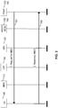
- FIG. 1 is a simplified block diagram illustrating the architecture of a system 100 for enabling NG eCall for LTE, according to an embodiment.
- the system includes a UE 105, which may be incorporated into and/or otherwise connected with an In-Vehicle System (IVS) 107, an LTE network (also referred to as an Evolved Packet System (EPS)) 102, a Legacy Emergency Services (ES) Network 145 with a Legacy PSAP 150, and a National Emergency Number Association (NENA) i3 Emergency Services IP network (ESInet) 155 with a NENA i3 capable PSAP 160.
- IMS In-Vehicle System
- EPS Evolved Packet System
- ES Legacy Emergency Services
- NENA National Emergency Number Association
- ESInet Emergency Services IP network
- the LTE network 102 may include an Evolved Node B (eNodeB, or eNB) 110, a Serving Gateway 115, a Packet Data Network (PDN) Gateway 120, a Mobility Management Entity (MME) 170, a Proxy Call Session Control Function (P-CSCF) 125, an Emergency Call Session Control Function (E-CSCF) 130, a Media Gateway Control Function (MGCF) 135, and a Media Gateway (MGW) 140.
- the MGCF 135 may be incorporated into or otherwise joined with the MGW 140. In other embodiments, such as the embodiment shown in FIG. 1 , they may be separately implemented and/or maintained.
- the system 100 may comprise other components (some of which are shown in FIG. 1 but which are not discussed in this disclosure), and other embodiments may add, omit, join, separate, rearrange, or otherwise alter components depending on desired functionality. Such variations will be recognized by a person of ordinary skill in the art.
- the IVS 107 may be part of a vehicle (e.g. a car or truck) and may support telematics services for NG eCall as previously described.
- the IVS 107 may include a UE 105 as an embedded component or may be connected to (e.g. coupled to) the UE 105 (e.g. via Bluetooth®).
- the UE 105 may support the signaling and voice transfer functions for NG eCall and may be similar to or the same as other wireless terminals (e.g. a cellular phone or smartphone) in terms of wireless communications capability.
- the IVS 107 may include other components (not shown in FIG.
- the eNB 110 may be a serving eNB for the UE 105 and may provide wireless communications access to the LTE network 102 on behalf of UE 105.
- the MME 170 may be a serving MME for the UE 105 and may support mobility of UE 105 and provision of signaling access and voice bearer paths.
- the serving gateway 115 and PDN gateway 120 may provide IP based signaling and IP transport support for UE 105 - e.g. with PDN gateway 120 assigning an IP address for UE 105 and providing IP access to other entities in LTE network 102 such MGW 140 and P-CSCF 125.
- LTE network 102 may include an IP Multimedia Subsystem (IMS) 180 that may include the P-CSCF 125, E-CSCF 130, MGCF 135 and LRF 190.
- IMS 180 may support an NG eCall from UE 105 to a PSAP such as i3 PSAP 160 or legacy PSAP 150.
- a signaling path from UE 105 may pass through the eNB 110, serving gateway 115, PDN gateway 120, P-CSCF 125, E-CSCF 130, an IBCF, the i3 ESInet 155 and i3 PSAP 160.
- a signaling path from UE 105 may pass through the eNB 110, serving gateway 115, PDN gateway 120, P-CSCF 125, E-CSCF 130, a BGCF, MGCF 135, the legacy ES Network 145 and legacy PSAP 150.
- Elements in IMS 180 may provide call handling and call routing support to enable an NG eCall from UE 105 to either i3 PSAP 160 or legacy PSAP 150.
- P-CSCF 125 may detect an NG eCall when instigated by UE 105 (e.g.
- E-CSCF 130 may support routing of an NG eCall from UE 105 (e.g. by sending a SIP INVITE from UE 105 received via P-CSCF 125 towards either legacy PSAP 150 via MGCF 135 or i3 PSAP 160 via an IBCF).
- LRF 190 may assist routing of an NG eCall from UE 105 when queried by E-CSCF 130. For example, LRF 190 may determine a location for UE 105 (e.g. from information provided by UE 105 in a SIP INVITE) and may determine a PSAP (e.g.
- legacy PSAP 150 or i3 PSAP 160 that supports an NG eCall for that location and may return an identity or address for this PSAP to E-CSCF 130.
- MGCF 135 may perform conversion of SIP based signaling, received from or sent to UE 105, to or from signaling used by ES network 145 such as ISUP signaling in the case of an NG eCall to legacy PSAP 150.
- MGCF 135 may partly convert an NG eCall received from UE 105 into a Circuit Switched (CS) eCall in the case of an NG eCall routed to legacy PSAP 150.
- CS Circuit Switched
- ESInet 155 may support IP based emergency calls including an NG eCall from UE 105 on behalf of i3 PSAP 160 - e.g. may route an NG eCall from UE 105 to i3 PSAP 160.
- Legacy ES network 145 may similarly support Circuit Switched (CS) based emergency calls on behalf of legacy PSAP 150 including a CS eCall (also referred to as just an eCall) received via MGCF 135 from UE 105 - e.g. may route a CS eCall from UE 105 received via MGCF 135 to legacy PSAP 150.
- MGW 140 may convert between VoIP received from or sent to UE 105 and CS based voice sent to or received from legacy PSAP 150 in the case of an NG eCall from UE 105 to legacy PSAP 150.
- the signaling path from the UE 105 to the legacy PSAP 150 communicatively connects the UE 105 with the Legacy PSAP 150 and is used to transfer signaling messages (e.g. SIP messages, ISUP messages) and/or other signals (e.g. MF tones).
- this path includes the following chain of elements: UE 105, eNB 110, Serving Gateway 115, PDN Gateway 120, P-CSCF 125, E-CSCF 130, MGCF 135, Legacy ES Network 145, and Legacy PSAP 150.
- the voice path (also referred to as a voice media path, media path, data path, voice channel, audio channel, audio path) for an NG eCall from the UE 105 to the legacy PSAP 150, marked with a solid bolded line, communicatively connects the UE with the legacy PSAP 150.
- This path includes the following chain of components: UE 105, eNB 110, Serving Gateway 115, PDN Gateway 120, MGW 140, legacy ES Network 145, and legacy PSAP 150.
- Communication of signaling e.g.
- SIP messages) from the UE 105 to the MGCF 135 is typically packet switched (PS) (e.g., SIP transported using TCP or UDP over IP), while communication of signaling from the MGCF 135 to the legacy PSAP 150 may be based on SS7 (e.g. ISUP) and/or may use in-band MF signaling, although embodiments may vary.
- PS packet switched
- CS circuit switched
- audio, voice, data, signaling and/or other communication that is sent from UE 105 to or towards legacy PSAP 150 or i3 PSAP 160 or to or towards any element in the LTE network 102 is referred as being transferred, sent or received "uplink” or in an "uplink direction”.
- audio, voice, data, signaling and/or other communication that is sent from legacy PSAP 150, i3 PSAP 160 or any element in LTE network 102 to or towards UE 105 is referred as being transferred, sent or received "downlink” or in a "downlink direction”.
- FIG. 2 is a signaling flow illustrating how various components of the system 100 of FIG. 1 can establish an NG eCall, resulting in an in-band MSD transfer, as discussed previously.
- some principal elements but not all elements of the LTE network 102 are shown.
- Some actions attributed to or implied for certain elements or certain groups of elements of the LTE network 102 shown in FIG. 2 may therefore be supported in part by other elements not shown in FIG. 2 .
- references to actions performed by or involving MME 170 can be assisted or provided by the eNB 110, Serving Gateway 115, PDN Gateway 120, and/or other components of FIG. 1
- the IMS 180 can refer to the P-CSCF 125 and/or the E-CSCF 130 of FIG. 1 , or may correspond to all the elements of the IMS 180.
- techniques disclosed herein are not necessarily limited to the architecture illustrated in FIG. 1 .
- establishing an NG eCall from UE 105 to legacy PSAP 150 can be performed in nine phases each comprising one or more stages, as follows.
- Phase 1 the IVS 107 (not shown in FIG. 2 ) detects an emergency situation either via manual user input (e.g., a driver or passenger of a vehicle presses an emergency help button) or automatically using sensors (e.g., sensing an abrupt acceleration/deceleration, air-bag deployment, fire, water, etc.) and informs the UE 105 at stage 201.
- manual user input e.g., a driver or passenger of a vehicle presses an emergency help button
- sensors e.g., sensing an abrupt acceleration/deceleration, air-bag deployment, fire, water, etc.
- Phase 2 the UE 105 performs domain selection at stage 202 to select either the CS or PS domain and find an accessible wireless network supporting this domain. If the CS domain is selected (not shown in FIG. 2 ), a CS eCall is instigated. If the PS domain is selected, LTE network 102 is accessed in this example and the rest of the actions in FIG. 2 are performed.
- Phase 3 UE 105 attaches to LTE network 102 at stage 203 if not already attached (e.g. if the UE 105 is configured for eCall only mode and only attaches to a wireless network to instigate an eCall, test call, or call to a home network operator).
- the attachment at stage 203 is supported by MME 170 and by other elements not shown in FIG. 2 such as eNB 110 and PDN gateway 120.
- UE 105 obtains an emergency bearer and discovers a P-CSCF 125 suitable for emergency services.
- the UE 105 may release resources (e.g. bearer resources) for any previous ongoing sessions if needed to perform this phase.
- Phase 4 the UE 105 performs an emergency IMS registration at stage 204 with the IMS 180.
- the emergency IMS registration at stage 204 may also be performed with the IMS in a home network for the UE 105 (not shown in FIG. 2 ) if the UE 105 is roaming (e.g. if LTE network 102 is not the home network for UE 105).
- Phase 5 the UE 105 sends a SIP INVITE message to the IMS 180 (e.g. to the P-CSCF 125) at stage 205.
- the INVITE sent at stage 205 may contain an eCall indication, which may indicate an emergency call and whether the eCall was manually or automatically invoked, and telematics data which in this example comprises MSD.
- the MSD may not be included in the SIP INVITE sent at stage 205 and UE 105 may instead attempt to send the telematics data (e.g. after the NG eCall is established) using alternative techniques, such as by using a separate data channel which may be established in parallel with or after establishment of the voice path during phase 8.
- the IMS 180 may query the LRF 190 to obtain call routing and/or location information for the UE 105 and the LRF 190 may obtain the location of the UE (e.g. via an interaction involving the MME 170 and/or UE 105) in order to provide call routing and/or location information.
- the IMS 180 e.g. the E-CSCF 130
- the LRF 190 may obtain the location of the UE (e.g. via an interaction involving the MME 170 and/or UE 105) in order to provide call routing and/or location information.
- Phase 7 The IMS 180 (e.g. the E-CSCF 130) uses any routing information obtained in phase 6 (e.g. provided by LRF 190) or selects an emergency center or PSAP based on information provided in phase 5 and sends the NG eCall request (e.g. SIP INVITE message) including the eCall indication, MSD and any location information obtained in phase 5 or phase 6 to or towards the emergency center or PSAP. If the emergency center or PSAP is accessed over the CS domain (i.e., the PSAP is a legacy PSAP 150), actions 7a and 7b are performed. For action 7a: the SIP INVITE is sent to MGCF 135 at stage 207a.
- the NG eCall request e.g. SIP INVITE message
- the MGCF 135 sends an ISUP Initial Address Message (IAM) towards the legacy PSAP 150 (e.g. sends the IAM to the legacy ES network 145) at stage 207b.
- the IAM may carry an emergency indication (e.g. in a Calling Party's Category parameter) and an eCall indication.
- the indication of an eCall or an indication of call routing to a PSAP that supports eCall may be carried as part of a Called Party Number parameter (e.g. by including certain digits in the Called Party Number parameter) and may not be carried as a separate indication in the IAM.
- the MSD may be discarded by the MGCF 135 as part of stage 207b.
- actions 7c, 7d and 7e are performed.
- the IMS 180 e.g. the E-CSCF 130
- the i3 PSAP 160 returns a SIP STATUS message at stage 207d (e.g. a SIP 200 OK message) to the IMS 180 (e.g.
- the SIP STATUS message carries a confirmation of MSD receipt and possibly an agreement to establish the NG eCall.
- the IMS 180 e.g. the E-CSCF 130 and P-CSCF 125
- the STATUS message sends the STATUS message to the UE 105 at stage 207e, confirming receipt of the MSD.
- a similar STATUS message such as an ISUP Answer (ANM) message, may be sent by the legacy PSAP 150 after performing actions 7a and 7b as part of phase 8.
- this STATUS message e.g. ANM message
- Phase 8 the emergency call establishment is completed at stage 208.
- This includes establishing a voice path (also referred to as a voice channel or audio channel) between the UE 105 and the PSAP (either legacy PSAP 150 or i3 PSAP 160).
- the voice path may employ VoIP and not need any conversion between different voice encodings.
- the voice path may go through MGW 140 associated with the MGCF 135 and may also go through other entities as described for FIG. 1 and may undergo one or more transformations such as conversion between VoIP encoding and CS voice encoding at MGW 140.
- Phase 9 if the UE 105 does not receive the STATUS message for stage 207e (e.g. the NG eCall is sent to legacy PSAP 150 via the CS domain in stages 207a and 207b) or if the STATUS message received at stage 207e does not contain a confirmation of successful MSD receipt by the PSAP (e.g. by legacy PSAP 150), then at stage 209, the UE 105 attempts to transfer the MSD to the emergency center or PSAP via in-band means over the voice path established in phase 8, as mentioned previously.
- stage 207e e.g. the NG eCall is sent to legacy PSAP 150 via the CS domain in stages 207a and 207b
- the STATUS message received at stage 207e does not contain a confirmation of successful MSD receipt by the PSAP (e.g. by legacy PSAP 150)
- the UE 105 attempts to transfer the MSD to the emergency center or PSAP via in-band means over the voice path established in phase 8, as mentioned previously.
- the UE 105 may send the MSD over the voice path to the legacy PSAP 150 without waiting for a request from the legacy PSAP 150 or may wait for an in-band request from the legacy PSAP 150 (sent over the voice path to the UE 105) before sending the MSD to the legacy PSAP 150 over the voice path.
- FIG. 3 is a signaling flow illustrating the transfer of an updated MSD from the UE 105 to the legacy PSAP 150 or i3 PSAP 160 - e.g. following establishment of an NG eCall according to the example in FIG. 2 .
- the actions illustrated in FIG. 3 can represent an example method of transferring MSD in-band to legacy PSAP 150 accessed via the CS domain (e.g., implementing phase 9 in FIG. 2 and where actions 7a and 7b are performed in FIG. 2 ).
- the actions in FIG. 3 may alternatively or additionally represent a way in which updated MSD is sent to i3 PSAP 160 accessed via the PS domain - e.g.
- the legacy PSAP 150 may send a request for MSD to the UE 105 using in-band means over a voice path between the UE 105 and the legacy PSAP 150.
- the UE 105 responds by, at action 2 and at stage 302, sending the MSD to the legacy PSAP 150 using in-band means over the voice path.
- the voice path may pass through MGW 140 as previously described, in which case both the request for MSD sent at stage 301 and the MSD sent at stage 302 are transferred in-band via the MGW 140.
- the MSD When MSD is transferred from a UE to a PSAP by in-band means over a voice path between the UE and the PSAP (e.g. as at stage 209 in FIG. 2 and as at stage 302 in FIG. 3 ), the MSD is converted into audio signals (also referred to as audio tones) using a data modem in the UE.
- a data modem also referred to as an in-band modem, an in-band data modem, an eCall data modem or an eCall in-band modem
- 3GPP 3GPP Technical Specification
- the audio signals output by the data modem encode the sequence of bits that comprise the MSD and enable sending of the MSD by analog means over the voice path rather than by digital means as a sequence of bits sent over a signaling path.
- the audio signals are transferred to the PSAP over the voice path and converted back into the MSD at the PSAP using the same type of data modem as at the UE but used for the reverse transformation. While the MSD is being transferred, speech from a user of the UE (e.g. a driver or passenger of a vehicle) cannot be sent by the UE to the PSAP. In some cases, speech from a PSAP operator also cannot be sent to the user of the UE.
- This interruption of the voice path may be disconcerting or even disturbing to the user and/or to the PSAP operator and may cause either party to disconnect (or attempt to disconnect) the call if persistent (e.g. if lasting longer than 10 to 15 seconds). For this reason, MSD transfer that occurs in-band needs to occur quickly. For example, 3GPP has mandated that MSD transfer for an eCall shall occur within 4 seconds when transfer is via in-band means.
- DJB adaptive de-jitter buffering
- LTE employs VoIP transfer of voice communication rather than CS transfer in order to improve bandwidth efficiency which requires use of an adaptive DJB to deliver speech frames to a speech decoder at a constant rather than varying rate.
- an adaptive DJB is typically allocated a limited buffer size (e.g.
- buffer overflow when incoming packetized voice is arriving too quickly thereby risking packet loss
- buffer underflow when incoming packetized voice is arriving too slowly thereby risking having no speech frames available to send to a speech decoder
- time-warping packetized voice may be compressed when buffer overflow is imminent and may be expanded when buffer underflow is imminent.
- references to the use of adaptive DJB herein may include use of time-warping even when not specifically mentioned.
- a call from a UE 105 may be received by an MGCF 135, which identifies the call as an NG eCall.
- the MGCF 135 can then relay this information to the MGW 140, instructing the MGW 140 to disable adaptive DJB and instead employ a deeper, static DJB, thereby making the in-band transferred MSD less likely to be corrupted by packet-dropping and/or the need for time warp distortion.
- the MGCF 135 can also negotiate with the UE 105 (e.g. as part of phase 5, phase 7 and phase 8 in FIG. 2 ) a higher bit rate codec and/or a codec type that is known to support MSD transfer better than others and can reduce the impacts of signal compression.
- MGCF 135 can occur between the UE 105 and MGCF 135 using the Session Description Protocol (SDP) which may be carried in SIP messages (or other messages) as part of the establishment of an NG eCall - e.g. such as the SIP INVITE for phase 5 and for action 7a and the SIP STATUS for action 7e in FIG. 2 .
- SDP Session Description Protocol
- the MGCF 135 is notified of the codec types and bit rates that the UE 105 supports in an SDP body carried in the initial SIP INVITE sent by the UE 105 to establish an NG eCall (e.g. as at action 7a in FIG.
- the MGCF 135 may be in a unique position to do this because (a) the MGCF 135 can be aware that an NG eCall is being established via an eCall indication in the initial SIP INVITE (e.g. the SIP INVITE for action 7a in FIG. 2 ) and (b) the MGCF 135 can be aware that the eCall will reach the legacy PSAP 150 via circuit means due to being the signaling interworking point between the IMS/PS domain (on the network side) and the CS domain (on the legacy PSAP 150 side).
- an eCall indication in the initial SIP INVITE e.g. the SIP INVITE for action 7a in FIG. 2
- the MGCF 135 can be aware that the eCall will reach the legacy PSAP 150 via circuit means due to being the signaling interworking point between the IMS/PS domain (on the network side) and the CS domain (on the legacy PSAP 150 side).
- the UE 105 may additionally or alternatively include only codec types and bit rates in the initial SIP INVITE (e.g. sent at phase 5 in FIG. 2 ) that are favorable to reduce degradation and corruption of in-band transfer.
- the MGCF 135 may convey the chosen codec, bit rate and optionally an eCall indication to the MGW 140.
- the MGW 140 can transfer the MSD information to the legacy PSAP 150, e.g., by depacketizing, decoding, and re-encoding the VoIP communication received from the UE to PCM A-law.
- the process of depacketizing, decoding and re-encoding by the MGW 140 can be performed to reduce or minimize corruption to the MSD (still encoded as audio signals when passing through the MGW 140) as already mentioned.
- the converted MSD (e.g. in the form of audio signals encoded using PCM A-law) may be transferred through one or more intermediate switches to the legacy PSAP 150 where the MSD may be decoded using a data modem.
- the in-band transfer of the MSD may occur as follows at a more detailed level.
- the UE 105 may first convert the MSD into audio (analog) signals using an eCall data modem (action U1), then encode the resulting audio signals into a digital (bit) stream using a codec negotiated between the UE 105 and MGCF 135 (action U2), then packetize the resulting digital stream into VoIP packets (e.g. using the Real Time Protocol (RTP)) (action U3) and finally send the VoIP packets towards the MGW 140 (action U4) using the IP based voice path established for the eCall (e.g. as at phase 8 in FIG. 2 ).
- RTP Real Time Protocol
- the MGW 140 may perform some reverse operations comprising depacketizing the received VoIP packets into a digital stream (action M1), decoding the digital stream using the negotiated codec into information representing audio signals (action M2) and re-encoding the information representing audio signals into a circuit switched digital bit stream using a different codec - e.g. for PCM A-law (action M3).
- the transformed (transcoded) digital stream may then be sent to the PSAP 150 (action M4).
- the circuit switched digital bit stream may be converted back into audio signals (action PI) from which the MSD may be extracted using the eCall data modem (action P2).
- the MGW 140 may use knowledge of an eCall supplied by MGCF 135 to modify action M1 and/or action M2 to reduce degradation and corruption of the encoded MSD and facilitate more reliable MSD recovery by PSAP 150 at action P2.
- Actions M1, M2 and M3 may be referred to as transcoding.
- the adaptive DJB can again be utilized by the MGW 140, to help facilitate any ensuing voice conversation conducted over the LTE voice channel during the eCall.
- the UE 105 may receive a High-Level Acknowledgement (HL-ACK) message from the legacy PSAP 150, indicating the MSD transmission is complete and a voice conversation can start. This can cause the system to revert to using the adaptive DJB.
- HL-ACK High-Level Acknowledgement
- Such functionality may be implemented in various ways.
- the MGW 140 can monitor and interpret the voice channel between the UE 105 and PSAP 150 in order to detect and recognize in-band messages sent from the legacy PSAP 150 to the UE 105.
- the MGW 140 can be configured to understand (e.g., fully or partially decode) data modem messages and protocol.
- the MGW 140 detects an in-band message from the PSAP 150, it can enable or disable adaptive DJB on the uplink portion of the voice channel (UE 105 to PSAP 150 direction) as appropriate to the detected in-band message. For example, if the MGW 140 detects a request for MSD (e.g. as sent at action 1 in FIG.
- the MGW 140 can disable adaptive DJB on the uplink in expectation of MSD being sent in the uplink (e.g. as at action 2 in FIG. 3 ).
- the MGW 140 detects an HL-ACK, it can enable adaptive DJB on the uplink based on assuming that MSD was successfully sent in the uplink (e.g. as at phase 9 in FIG. 2 ) and that the uplink will now be used to send normal speech.
- the MGW 140 can monitor communication for in-band messages from the legacy PSAP 150 and/or from the UE 105 without interpretation.
- the MGW 140 may not need to understand in-band messages (e.g., may not need to be familiar with the protocol used), but instead, can merely detect their presence (e.g., via signal analysis to determine whether one or more characteristics of in-band signaling is/are present).
- the MGW 140 does not detect in-band messages for some time, it can re-enable adaptive DJB in the uplink UE 105 to PSAP 150 direction.
- the MGW 140 may be able to later disable adaptive DJB to allow the MGW 140 to continue transferring the MSD (e.g.
- MGW 140 mistakenly re-enables adaptive DJB too early and later detects in-band signaling is still in use). For instance, as soon as the MGW 140 detects in-band messages it may disable adaptive DJB. In some embodiments, after MGW 140 stops detecting in-band messages, MGW 140 may delay re-enabling adaptive DJB for a timeout period of a few seconds (e.g. 5 seconds) in order to ensure that in-band signaling has stopped. If in-band signaling is again detected prior to expiration of the timeout period, MGW 140 may not re-enable adaptive DJB.
- the UE 105 when the UE 105 receives an HL-ACK message from PSAP 150 confirming successful transfer of the MSD from UE 105 to PSAP 150, the UE 105 can send a SIP message (e.g. a SIP INFO message) to the MGCF 135, telling the MGCF 135 to signal to the MGW 140 that it can re-enable adaptive DJB.
- a SIP message e.g. a SIP INFO message
- the UE 105 when the UE 105 receives a request for MSD from PSAP 150 (e.g. as at action 1 in FIG. 3 ), the UE 105 can send a SIP message (e.g. a SIP INFO message) to the MGCF 135, telling the MGCF 135 to signal to the MGW 140 that it should disable adaptive DJB. UE 105 may then send MSD in-band to PSAP 150 - e.g. possibly after a short delay of 1 or 2 seconds to enable MGW 140 to first disable adaptive DJB.
- a SIP message e.g. a SIP INFO message
- Some embodiments may further employ an MGW 140 that detects an uplink START message from the legacy PSAP 150 that may be sent in-band to UE 105 to request transfer of updated MSD (e.g. as at action 1 in FIG. 3 ). After detecting a START message, MGW 140 may disable adaptive DJB on its uplink (for the UE 105 to PSAP 150 direction of transfer). In such an embodiment, when the MGW 140 detects a START message from PSAP 150, MGW 140 may tell the MGCF 135 to signal this to the UE 105 via SIP signaling (e.g. by sending a SIP INFO message).
- the UE 105 may disable adaptive DJB on its downlink (for the PSAP 150 to UE 105 direction of transfer). Such functionality may enable the legacy PSAP 150 to request the UE 105 to re-send the MSD (e.g., when a better position fix for UE 105 is available). The UE 105 may also detect the START message from PSAP 150 and disable adaptive DJB on its downlink.
- FIG. 4 is a simplified block diagram illustrating a buffering and decoding process 400 that can be performed by the UE 105 to help the UE 105 reliably detect and decode an uplink in-band message (e.g. a START message) that was sent to UE 105 by PSAP 150 using a data modem.
- the buffering and decoding process 400 may be implemented in hardware and/or software on the UE 105, and may be incorporated into one or more larger components of the UE 105, such as a modem or other communication interface, a processor, and the like.
- the buffering and decoding process 400 can receive a VoIP input in a downlink direction (e.g., VoIP communication from the legacy PSAP 150 over an LTE voice channel).
- the input is then provided to two DJBs.
- a first DJB can comprise an adaptive DJB 410 which is delivering encoded audio frames (e.g. speech frames) to the audio decoder 430.
- the output of the audio decoder 430 may comprise an audio stream (e.g. speech) which is provided to a switch 450.
- the switch 450 may transparently pass through the audio stream from the audio decoder 430 as the output of the buffering and decoding process 400 which may be provided to a user of UE 105 (e.g.
- the adaptive DJB 410 may buffer received VoIP (e.g. RTP) packets for a limited time (e.g. 20-40 ms) before outputting encoded audio frames in order to limit end to end audio delay and avoid the user of UE 105 and operator at PSAP 150 from experiencing a noticeable delay in voice replies from the other party. This may introduce time warping and audio (e.g. speech) clipping as previously described.
- a second DJB can comprise a static DJB 420 whose output is being fed into an audio decoder 440 which may be similar to or the same as the audio decoder 430.
- the static DJB 420 may buffer received VoIP (e.g.
- RTP Real-Time Transport Protocol
- the audio stream output from the audio decoder 440 may be passed to a data modem 460 which may detect any message content sent in-band.
- the output of the data modem 460 may be passed to a message decoder 470 which may determine whether an in-band message is present and the content of the in-band message.
- the data modem 460 and message decoder 470 may be combined.
- the data modem 460 combined with the message decoder 470 may be referred to as an In-band message detector 480.
- the audio output of the buffering and decoding process 400 may be provided from the output of the adaptive DJB 410 and the audio decoder 430, which may pass transparently through the switch 450 as previously described.
- the in-band message detector 480 e.g. the message decoder 470
- the switch 450 can signal the switch 450 to cease transferring the audio output from the audio decoder 430 to the user. This may avoid the user hearing the data modem tones used to transfer any message sent via the data modem (e.g. a START message) and thereby avoid disturbing the user.
- the in-band message detector 480 e.g.
- the message decoder 470 may decode the in-band message that was detected and provide an indication of the message (e.g. the message identity and any message content) to one or more other elements in the UE 105 such as an application processor or process that is supporting eCall transfer of MSD in UE 105. Because encoded audio frames from the static DJB 420 rather than adaptive DJB 410 are passed into the audio decoder 440, there can be less or no time-warping distortion of the data modem signal, allowing the in-band message detector 480 to more reliably detect and decode any in-band message. When the in-band message detector 480 (e.g. the message decoder 470) no longer detects an in-band signal, or possibly following some timeout period (e.g.
- in-band message detector 480 may signal the switch 450 to resume passing through the audio stream from audio decoder 430 to the user of UE 105 (e.g. to a playback device not shown in FIG. 4 ).
- the static DJB 420, audio decoder 440, in-band message detector 480 and switch 450 may be part of a subsystem 495 (shown by the dashed box in FIG. 4 ).
- the buffering and decoding process 400 for the voice path may make use of just the adaptive DJB 410 and the audio decoder 430 but may not make use of (e.g. may exclude) the elements comprising the subsystem 495.
- the VoIP input may only pass through the adaptive DJB 410 and audio decoder 430 (and not the static DJB 420 and audio decoder 440) and the output of the audio decoder 430 may be sent to a playback device.
- UE 105 may modify the buffering and decoding process 400 for the voice path by including the elements of subsystem 495 as part of the buffering and decoding process 400 as described previously.
- FIG. 5 is a simplified block diagram illustrating transcoding in MGW 140 using a transcoding process 500.
- Transcoding process 500 may enable MGW 140 to convert an uplink audio stream received from UE 105 in the form of VoIP (e.g. RTP) packets into a circuit switched digital audio stream (e.g. encoded according to PCM A-law) suitable for onward transfer to a legacy PSAP 150.
- Transcoding process 500 may be similar to buffering and decoding process 400 in FIG. 4 and may employ certain functionally similar elements.
- the transcoding process 500 may be implemented in hardware and/or software in the MGW 140, and may be incorporated into one or more larger components of the MGW 140, such as a communication interface, a processor, and the like.
- the transcoding process 500 can receive a VoIP input in an uplink direction (e.g., VoIP communication from the UE 105 that is received by MGW 140 from a PDN Gateway 120.)
- the input is then provided to two DJBs.
- a first DJB can comprise an adaptive DJB 510 which is delivering encoded audio frames (e.g. speech frames) to the audio decoder 530.
- the audio decoder 530 may support a codec previously negotiated and agreed with a UE 105 (e.g. during a call establishment phase 8 as described for FIG. 2 ).
- the output of the audio decoder 530 may comprise an audio stream (e.g. speech), or information representative of an audio stream (e.g.
- PCM encoded audio which is provided to a switch 550.
- the switch 550 may transparently pass through the audio stream from the audio decoder 530 to a CS audio encoder 590 which may re-encode the audio stream (or information representative of an audio stream) into a digital stream (e.g. PCM A-law) suitable for transfer to a legacy PSAP 150 by CS means (e.g. over a PSTN).
- the adaptive DJB 510 may buffer received VoIP (e.g. RTP) packets for a limited time (e.g. 20-40 ms) before outputting encoded audio frames in order to limit end to end audio delay. This may introduce time warping and audio (e.g. speech) clipping into the audio stream.
- a second DJB for the transcoding process 500 in FIG. 5 can comprise a static DJB 520 whose output is being fed into an audio decoder 540 which may be similar to or the same as the audio decoder 530.
- the static DJB 520 may buffer received VoIP (e.g. RTP) packets for longer than adaptive DJB 510 (e.g. 100 ms to 200 ms) in order to avoid loss of audio frames and time warping.
- the audio stream output from the audio decoder 540 may be passed to an in-band message detector 580 which may be functionally similar to or the same as the in-band message detector 480 described in association with FIG. 4 .
- in-band message detector 580 may not need to decode and interpret in-band messages (unlike in-band message detector 480), in-band message detector 580 may be simpler than in-band message detector 480 (e.g. may not include a data modem element functionally similar to or the same as data modem 460).
- the output of the audio decoder 540 may also be passed to the switch 550.
- the switch 550 may transparently pass through the audio output of the audio decoder 530 to the CS audio encoder 590, as previously described, and may block the transfer of the audio output from the audio decoder 540.
- the in-band message detector 580 detects an in-band signal (e.g.
- the in-band message detector 580 can signal the switch 550 to transition from a normal mode of operation to an in-band signal mode of operation. While in the in-band signal mode of operation, switch 550 may block the transfer of the audio output from the audio decoder 530 and may instead transparently pass the audio output of the audio decoder 540 to the CS audio encoder 590. This may avoid time warping and audio clipping in the transferred audio output to CS audio encoder 590 since the audio output transferred in the in-band mode of operation will have gone through the static DJB 520.
- the digital audio output of the CS digital encoder 590 that is transferred to PSAP 150 may enable PSAP 150 to more reliably detect and decode any in-band message content (e.g. MSD) than if PSAP 590 was receiving digital audio output that had previously passed through the adaptive DJB 510.
- in-band message detector 580 may signal the switch 550 to resume the normal mode of operation in which the audio stream from audio decoder 530 rather than audio decoder 540 is transferred transparently to the CS audio encoder 590.
- the normal mode of operation may reduce end-to-end audio delay which may avoid the user of UE 105 and an operator of PSAP 150 from noticing any significant delay in receiving replies (e.g. speech replies) from the other party.
- the switch 550 may be configured to begin using the in-band signal mode of operation (in which audio output from the static DJB 520 and audio decoder 540 rather than dynamic DJB 510 and audio decoder 530 is passed through the switch 550 to the CS audio encoder 590) as soon as the audio channel is established and transcoding process 500 begins to be used. This may occur at MGW 140 based on MGW 140 being aware that UE 105 will typically transfer in-band signals (e.g. containing MSD) to the PSAP 150 destination when or soon after the audio channel between UE 105 and PSAP 150 is established (e.g. as at phase 8 in FIG. 2 ).
- in-band signal mode of operation in which audio output from the static DJB 520 and audio decoder 540 rather than dynamic DJB 510 and audio decoder 530 is passed through the switch 550 to the CS audio encoder 590. This may occur at MGW 140 based on MGW 140 being aware that UE 105 will typically transfer in-band signals (e.g. containing
- MGW 140 may be aware of the imminent in-band signaling from UE 105 to PSAP 150 due to receiving an indication of an eCall or an indication of in-band signal transfer on the audio channel from MGCF 135 (e.g. which may occur during call establishment and as part of phase 8 in the example of FIG. 2 ).
- the static DJB 520, audio decoder 540, in-band message detector 580 and switch 550 may be part of a subsystem 595 (shown by the dashed box in FIG. 5 ).
- the transcoding process 500 for the audio channel may make use of just the adaptive DJB 510, the audio decoder 530 and the CS audio encoder 590 but may not make use of (e.g. may exclude) the elements comprising the subsystem 595.
- the VoIP input to the transcoding process may only pass through the adaptive DJB 510 and audio decoder 530 (and not the static DJB 520 and audio decoder 540) and the output of the audio decoder 530 may always be sent to the CS audio encoder 590.
- MGW 140 may modify the transcoding process 500 by including the elements of subsystem 595 as part of the transcoding process 500 as described previously.
- embodiments may cause the UE 105 and/or MGW 140, once an eCall is known (e.g. due to receiving an eCall indication from MGCF 135 in the case of MGW 140 or due to establishing an NG eCall to a PSAP 150 where a confirmation of MSD transfer from PSAP 150 is not received in the case of UE 105), to increase their minimum adaptive de-jitter buffering level by a small amount (e.g., by 20-40 ms). This increase may give their in-band signal detector additional time (e.g., one or more additional audio frames) to process and more reliably detect an in-band signal.
- a small additional delay (e.g., 20-40 ms) may be tolerable to a user of UE 105 and an operator of PSAP 150.
- the in-band signal detector can wait to process one or two more voice frames before deciding whether to perform even deeper buffering for static mode operation, or to continue with adaptive de-jitter buffering.
- the techniques described herein can be utilized in NG eCall initiation in an LTE system, but embodiments are not so limited.
- the disclosed techniques may be utilized more generally to increase the reliability of data received via in-band signaling in a broad variety of applications.
- the techniques may be employed in systems that employ IP based communication including VoIP communication between two entities (e.g. a client user and a service provider) where one of the entities can only be accessed via circuit switched means (e.g. over a Public Switched Telephone Network (PSTN)) and where data transfer between the two entities needs to employ in-band signaling over the voice (or audio) channel between the two entities.
- PSTN Public Switched Telephone Network
- FIG. 6 is a flow diagram 600 illustrating a method of increasing the reliability of the transfer of data (e.g. telematics data such as MSD) received via in-band signaling, according to one embodiment.
- the method may be employed by a UE 105, an MGCF 135 or an MGW 140.
- FIG. 6 is provided as a non-limiting example. Alternative embodiments may include additional functionality to that shown in the figure, and/or the functionality shown in one or more of the blocks in the figure may be omitted, combined, separated, and/or performed simultaneously.
- Means for performing the functionality of the blocks may include one or more hardware and/or software components, such as those described with regard to the computer system of FIG. 9 below. A person of ordinary skill in the art will recognize many variations.
- an indication of in-band signaling is obtained, where the in-band signaling occurs in an audio channel (e.g. voice channel) of a communication network.
- the audio channel may correspond to the audio channel established according to the signaling flow in FIG. 2 between a UE 105 and a legacy PSAP 150.
- the functionality at block 620 comprises, in response to obtaining the indication of in-band signaling, causing a decoding process to modify the decoding of audio signals for the audio channel.
- the decoding process may correspond to part or all of the buffering and decoding process 400 for UE 105 as described in association with FIG. 4 .
- the decoding process may correspond to part or all of the transcoding process 500 for MGW 140 as described in association with FIG. 5 .
- the decoded audio signals whose decoding was modified in block 620, are provided to one of an in-band message detector (e.g. the in-band message detector 480 in FIG. 4 in the case of a UE 105 or the in-band message detector 580 in FIG. 5 in the case of an MGW 140), an audio encoder (e.g. the CS audio encoder 590 in FIG. 5 in the case of MGW 140) or an audio playback device (e.g. an audio playback device for a UE 105) based on the indication of in-band signaling obtained at block 610.
- an in-band message detector e.g. the in-band message detector 480 in FIG. 4 in the case of a UE 105 or the in-band message detector 580 in FIG. 5 in the case of an MGW 140
- an audio encoder e.g. the CS audio encoder 590 in FIG. 5 in the case of MGW 140
- an audio playback device e.g. an audio playback device for a UE
- the indication of in-band signaling in the audio channel may be obtained at block 610 by the UE 105 based on establishment of an eCall or NG eCall with a legacy PSAP 150 during which transfer of telematics data (e.g. MSD) by out-of-band means from UE 105 to the PSAP 150 is determined by UE 105 not to occur.
- telematics data e.g. MSD
- UE 105 may determine that MSD transfer does not occur by out-of-band means.
- an indication of in-band signaling may be obtained by a UE 105 at block 610 from an MGCF 135 - e.g. if legacy PSAP 150 sends a signal using circuit switched signaling (e.g. SS7 ISUP) to MGCF 135 when legacy PSAP 150 starts to send in-band signaling towards UE 105 and if MGCF 135 then forwards the signal to UE 105 using SIP based signaling.
- circuit switched signaling e.g. SS7 ISUP
- UE 105 may cause a decoding process in the UE 105 to modify the decoding of audio signals for the audio channel received in the downlink direction from legacy PSAP 150 at block 620 by employing a static DJB instead of an adaptive DJB for audio (e.g. voice) depacketization or by increasing the time interval for audio packet buffering in an adaptive DJB.
- a UE 105 may use a buffering and decoding process 400 as described for FIG. 4 and may modify the buffering and decoding process 400 in response to obtaining the indication of in-band signaling at block 610 by including the elements comprising the subsystem 495 as described in association with FIG. 4 .
- UE 105 may provide the decoded audio signals from block 620 to an in-band message detector and/or to an audio playback device.
- the decoded audio signals from the audio decoder 440 are provided to the in-band message detector 480.
- the audio output from the audio decoder 430 may be provided by the buffering and decoding process 400 to a playback device as described for FIG. 4 .
- the indication of in-band signaling may be obtained at a UE 105 at block 610 using a buffering and decoding process 400 as described in association with FIG. 4 in which an in-band message detector 480 detects an in-band signal in the audio channel.
- the indication of in-band signaling may be obtained at block 610 by the MGCF 135 based on helping to establish an eCall or an NG eCall between a UE 105 and a legacy PSAP 150 as in the example described in FIG. 2 .
- the MGCF 135 receives an indication of an NG eCall from IMS 180 (e.g. E-CSCF 130 in IMS 180) in a request to establish an eCall (e.g. as in action 7a in FIG. 2 ) and forwards the request to establish the eCall to a legacy PSAP 150 via circuit switched means but does not transfer the MSD (e.g.
- the MGCF 135 may transfer the indication of in-band signaling to MGW 140 (e.g. as part of instructions to MGW 140 to support the audio channel between UE 105 and legacy PSAP 150 using a codec and bit rate negotiated by MGCF 135 with UE 105), which may cause MGW 140 to modify a transcoding process which may be used by MGW 140 to support the audio channel established between the UE 105 and PSAP 150.
- the modification of the transcoding process by MGW 140 may modify the decoding of audio signals for the audio channel at block 620.
- the MGW 140 may use the transcoding process 500 described in association with FIG.
- an indication of in-band signaling at block 610 may be obtained by an MGCF 135 from UE 105 - e.g. if UE 105 sends a signal in a SIP message (e.g., SIP INFO message) to MGCF 135 when UE 105 is about to start to send in-band signaling (e.g., containing MSD) towards legacy PSAP 150.
- MGCF 135 may then cause a decoding process in MGW 140 to modify the decoding of audio signals for the audio channel at block 620 as previously described.
- the indication of in-band signaling may be obtained at block 610 by the MGW 140 from an MGCF 135 when MGCF 135 requests MGW 140 to support the transfer of the audio path between a UE 105 and legacy PSAP 150 as described previously for establishment of an eCall between a UE 105 and legacy PSAP 150.
- an indication of in-band signaling may be obtained by MGW 140 indirectly from legacy PSAP 150 - e.g. if legacy PSAP 150 sends an indication of in-band signaling to MGCF 135 using CS signaling (e.g.
- MGW 140 may cause a decoding process in MGW 140 to modify the decoding of audio signals for the audio channel in the uplink direction from UE 105 to legacy PSAP 150 at block 620 by employing a static DJB instead of an adaptive DJB for audio (e.g. voice) depacketization or by increasing the time interval for audio packet buffering in an adaptive DJB.
- MGW 140 may use a transcoding process 500 as described for FIG.
- MGW 140 may modify the transcoding process 500 in response to obtaining the indication of in-band signaling at block 610 by including the elements comprising the subsystem 595 as described in association with FIG. 5 .
- MGW 140 may provide the decoded audio signals from block 620 to an audio encoder - e.g. for onward transfer to legacy PSAP 150 by circuit switched means.
- the decoded audio signals from the audio decoder 540 are provided to the CS audio encoder 590 via the switch 550.
- the audio output from the audio decoder 530 may be provided by the transcoding process 500 to the CS audio encoder 590 as described for FIG. 5 .
- the indication of in-band signaling may be obtained at an MGW 140 at block 610 using a transcoding process 500 as described in association with FIG. 5 in which an in-band message detector 580 detects an in-band signal in the audio channel.
- a message may be sent (e.g., from an MGCF 135) to a device (e.g., a UE 105/IVS 107) generating in-band signaling for an audio channel, wherein the message is indicative of a codec to utilize for the audio channel that is also suitable for conveying the in-band signaling.
- the MGCF 135 can cause the bandwidth or bit rate of the audio channel to be increased (e.g., by selecting a relatively high-bandwidth codec to be used for the communication).
- FIG. 7 is a flow diagram 700 illustrating a method of increasing the reliability of the transfer of data received via in-band signaling, according to another embodiment.
- the method is generally similar to the method shown in FIG. 6 , with the functionality of blocks 710 and 730 in FIG. 7 repeating the functionality of blocks 610 and 630 (in FIG. 6 ) respectively.
- the functionality of block 720 includes "utilizing a modified decoding process to decode audio signals for the audio channel," as a consequence of which, the one or more components executing the functionality of block 720 may utilize the modified decoding process.
- the functionality of block 620 includes "caus[ing] a decoding process to modify the decoding of audio signals for the audio channel", as a consequence of which, the one or more components executing the functionality of block 620 may or may not utilize the modified decoding process.
- the method of FIG. 7 may be executed by a UE 105, an MGCF 135, and/or an MGW 140.
- FIG. 7 is provided as a non-limiting example. Alternative embodiments may include additional functionality to that shown in the figure, and/or the functionality shown in one or more of the blocks in the figure may be omitted, combined, separated, and/or performed simultaneously. Means for performing the functionality of the blocks may include one or more hardware and/or software components, such as those described with regard to the computer system of FIG. 9 below. A person of ordinary skill in the art will recognize many variations.
- FIG. 8 illustrates an embodiment of a UE 105, which can be utilized as described herein above.
- the UE 105 can be used in the system 100 for enabling NG eCalls for LTE of FIG. 1 .
- the UE 105 may be further incorporated into an IVS 107, which can include additional features.
- FIG. 8 is meant only to provide a generalized illustration of various components, any or all of which may be utilized as appropriate. It can be noted that, in some instances, components illustrated by FIG. 8 can be localized to a single physical device and/or distributed among various networked devices, which may be disposed at different physical locations.
- the UE 105 is shown comprising hardware elements that can be electrically coupled via a bus 805 (or may otherwise be in communication, as appropriate).
- the hardware elements may include a processing unit(s) 810 which can include without limitation one or more general-purpose processors, one or more special-purpose processors (such as digital signal processing (DSP) chips, graphics acceleration processors, application specific integrated circuits (ASICs), and/or the like), and/or other processing structure or means.
- DSP digital signal processing
- ASICs application specific integrated circuits
- some embodiments may have a separate DSP 820, depending on desired functionality.
- Buffering logic may be provided in the processing unit(s) 810 and/or wireless communication interface 830 (discussed below).
- the UE 105 also can include one or more input devices 870, which can include without limitation a touch screen, a touch pad, microphone, button(s), dial(s), switch(es), and/or the like; and one or more output devices 815, which can include without limitation a display, light emitting diode (LED), speakers, and/or the like.
- input devices 870 can include without limitation a touch screen, a touch pad, microphone, button(s), dial(s), switch(es), and/or the like
- output devices 815 which can include without limitation a display, light emitting diode (LED), speakers, and/or the like.
- LED light emitting diode
- the UE 105 may also include a wireless communication interface 830, which can include without limitation a modem, a network card, an infrared communication device, a wireless communication device, and/or a chipset (such as a Bluetooth device, an IEEE 802.11 device, an IEEE 802.15.4 device, a WiFi device, a WiMax device, cellular communication facilities, etc.), and/or the like.
- the wireless communication interface 830 may permit data to be exchanged with a network, wireless access points, other computer systems, and/or any other electronic devices described herein.
- the communication can be carried out via one or more wireless communication antenna(s) 832 that send and/or receive wireless signals 834.
- the wireless communication interface 830 can include separate transceivers to communicate with one or more wireless networks via base stations and/or access points (e.g., eNB 110 of FIG. 1 ).
- the one or more wireless networks can include various network types such as a Code Division Multiple Access (CDMA) network, a Time Division Multiple Access (TDMA) network, a Frequency Division Multiple Access (FDMA) network, an Orthogonal Frequency Division Multiple Access (OFDMA) network, a Single-Carrier Frequency Division Multiple Access (SC-FDMA) network, a WiMax network (IEEE 802.16), a Wireless Local Area Network (WLAN), and so on.
- CDMA Code Division Multiple Access
- TDMA Time Division Multiple Access
- FDMA Frequency Division Multiple Access
- OFDMA Orthogonal Frequency Division Multiple Access
- SC-FDMA Single-Carrier Frequency Division Multiple Access
- WiMax IEEE 802.16
- WLAN Wireless Local Area Network
- a CDMA network may implement one or more radio access technologies (RATs) such as cdma2000, Wideband-CDMA (W-CDMA), and so on.
- Cdma2000 includes IS-95, IS-2000, and/or IS-856 standards.
- a TDMA network may implement Global System for Mobile Communications (GSM), Digital Advanced Mobile Phone System (D-AMPS), or some other RAT.
- GSM Global System for Mobile Communications
- D-AMPS Digital Advanced Mobile Phone System
- An OFDMA network may employ LTE, LTE Advanced, and so on.
- LTE, LTE Advanced, GSM, and W-CDMA are described in documents from 3GPP.
- Cdma2000 is described in documents from a consortium named "3rd Generation Partnership Project 2" (3GPP2). 3GPP and 3GPP2 documents are publicly available.
- a WLAN may be an IEEE 802.11 ⁇ network, a Bluetooth network, an IEEE 802.15x network, or some other type of network.
- the techniques described herein may also be used for any combination of two or more wireless networks or for wireless networks combined with wireline networks (e.g. the Internet and/or PSTN).
- the UE 105 can further include sensor(s) 840.
- sensors can include, without limitation, one or more accelerometer(s), gyroscope(s), camera(s), magnetometer(s), altimeter(s), microphone(s), proximity sensor(s), light sensor(s), and the like.
- Some or all of the sensor(s) 840 can be utilized, among other things, to sense an emergency condition that may trigger an eCall or an NG eCall, as described herein.
- Embodiments of the UE 105 may also include an SPS receiver 880 capable of receiving signals 884 from one or more SPS satellites using an SPS antenna 882. Such positioning can be utilized to complement and/or incorporate the techniques described herein.
- the SPS receiver 880 can extract a position of the UE 105, using conventional techniques, from SPS space vehicles (SVs) of an SPS system or GNSS such as the Global Positioning System (GPS), Galileo, Glonass, Quasi-Zenith Satellite System (QZSS) over Japan, Indian Regional Navigational Satellite System (IRNSS) over India, Beidou over China, and/or the like.
- GPS Global Positioning System
- Galileo Galileo
- Glonass Glonass
- Quasi-Zenith Satellite System QZSS
- IRNSS Indian Regional Navigational Satellite System
- Beidou Beidou over China
- the SPS receiver 880 may receive signals from various augmentation systems (e.g., a Satellite Based Augmentation System (SBAS)) that may be associated with or otherwise enabled for use with one or more global and/or regional navigation satellite systems.
- a Satellite Based Augmentation System SBAS
- an SBAS may include an augmentation system(s) that provides integrity information, differential corrections, etc., such as, e.g., Wide Area Augmentation System (WAAS), European Geostationary Navigation Overlay Service (EGNOS), Multi -functional Satellite Augmentation System (MSAS), GPS Aided Geo Augmented Navigation or GPS and Geo Augmented Navigation system (GAGAN), and/or the like.
- WAAS Wide Area Augmentation System
- EGNOS European Geostationary Navigation Overlay Service
- MSAS Multi -functional Satellite Augmentation System
- GPS Aided Geo Augmented Navigation or GPS and Geo Augmented Navigation system (GAGAN) GPS Aided Geo Augmented Navigation or GPS and Geo Augmented Navigation system (GAGAN), and/or the like
- an SPS may include any combination of one or more global and/or regional navigation satellite systems and/or augmentation systems, and SPS signals may include SPS, SPS-like, and/or other signals associated with such one or more SPS.
- the SPS receiver 880 may be configured to determine or help determine a location (e.g. latitude and longitude coordinates) for UE 105, based on measuring SPS signals 884, either by itself or in combination with other elements of UE 105 such as processing unit(s) 810.
- the location may be determined periodically (e.g. at 1 or 2 second intervals) and may be included within telematics data (e.g. MSD) that UE 105 sends to a PSAP (e.g. legacy PSAP 150) when an eCall or NG eCall is instigated by UE 105 as in the example for FIG. 2 .
- PSAP e.g. legacy PSAP 150
- the UE 105 may further include and/or be in communication with a memory 860.
- the memory 860 can include, without limitation, local and/or network accessible storage, a disk drive, a drive array, an optical storage device, a solid-state storage device, such as a random access memory (“RAM”), and/or a read-only memory (“ROM”), which can be programmable, flash-updateable, and/or the like.
- RAM random access memory
- ROM read-only memory
- Such storage devices may be configured to implement any appropriate data stores, including without limitation, various file systems, database structures, and/or the like.
- the memory 860 of the UE 105 also can comprise software elements (not shown), including an operating system, device drivers, executable libraries, and/or other code, such as one or more application programs, which may comprise computer programs provided by various embodiments, and/or may be designed to implement methods, and/or configure systems, provided by other embodiments, as described herein.
- one or more procedures described with respect to the method(s) discussed above may be implemented as code and/or instructions executable by the UE 105 (and/or a processing unit 810 or DSP 820 within UE 105).
- code and/or instructions can be used to configure and/or adapt a general purpose computer (or other device) to perform one or more operations in accordance with the described methods.
- FIG. 9 illustrates an embodiment of a computer system 900, which may be incorporated, at least in part, into devices used to implement one or more of the components of the system 100 for enabling NG eCalls for LTE of FIG. 1 and/or components of a similar system configured to implement the techniques disclosed above.
- FIG. 9 provides a schematic illustration of one embodiment of a computer system 900 that can perform the methods provided by various other embodiments, such as the method described in relation to FIG.s 1 to 7 and/or the functionality of MGCF 135, MGW 140, and/or other components of an LTE system. It should be noted that FIG. 9 is meant only to provide a generalized illustration of various components, any or all of which may be utilized as appropriate.
- FIG. 9 is meant only to provide a generalized illustration of various components, any or all of which may be utilized as appropriate.
- FIG. 9 therefore, broadly illustrates how individual system elements may be implemented in a relatively separated or relatively more integrated manner.
- components illustrated by FIG. 9 can be localized to a single device and/or distributed among various networked devices, which may be disposed at different physical locations.
- the computer system 900 is shown comprising hardware elements that can be electrically coupled via a bus 905 (or may otherwise be in communication, as appropriate).
- the hardware elements may include processing unit(s) 910, which can include without limitation one or more general-purpose processors, one or more special-purpose processors (such as digital signal processing chips, graphics acceleration processors, and/or the like), and/or other processing structure, which can be configured to perform one or more of the methods described herein, including the method described in relation to FIG.s 1 to 7 .
- the computer system 900 also can include one or more input devices 915, which can include without limitation a mouse, a keyboard, a camera, a microphone, other biometric sensors, and/or the like; and one or more output devices 920, which can include without limitation a display device, a printer, and/or the like.
- input devices 915 can include without limitation a mouse, a keyboard, a camera, a microphone, other biometric sensors, and/or the like
- output devices 920 which can include without limitation a display device, a printer, and/or the like.
- the computer system 900 may further include (and/or be in communication with) one or more non-transitory storage devices 925, which can comprise, without limitation, local and/or network accessible storage, and/or can include, without limitation, a disk drive, a drive array, an optical storage device, a solid-state storage device, such as a random access memory (“RAM”), and/or a read-only memory (“ROM”), which can be programmable, flash-updateable, and/or the like.
- RAM random access memory
- ROM read-only memory
- Such storage devices may be configured to implement any appropriate data stores, including without limitation, various file systems, database structures, and/or the like.
- the computer system 900 might also include a communications subsystem 930, which can include wireless communication technologies managed and controlled by a wireless communication interface 933, as well as wired technologies.
- the communications subsystem can include a modem, a network card (wireless or wired), an infrared communication device, a wireless communication device, and/or a chipset, and/or the like.
- the communications subsystem 930 may include one or more input and/or output communication interfaces, such as the wireless communication interface 933, to permit data to be exchanged with a network, mobile devices (such as UE 105/IVS 107), other computer systems, and/or any other electronic devices described herein.
- mobile device and “UE” are used interchangeably herein to refer to any mobile communications device such as, but not limited to, mobile phones, smartphones, wearable devices, mobile computing devices (e.g., laptops, PDAs, tablets), embedded modems, and automotive and other vehicular computing devices.
- mobile communications device such as, but not limited to, mobile phones, smartphones, wearable devices, mobile computing devices (e.g., laptops, PDAs, tablets), embedded modems, and automotive and other vehicular computing devices.
- the computer system 900 will further comprise a working memory 935, which can include a RAM and/or or ROM device.
- Software elements shown as being located within the working memory 935, can include an operating system 940, device drivers, executable libraries, and/or other code, such as one or more application programs 945, which may comprise computer programs provided by various embodiments, and/or may be designed to implement methods, and/or configure systems, provided by other embodiments, as described herein.
- one or more procedures described with respect to the method(s) discussed above may be implemented as code and/or instructions executable by a computer (and/or a processing unit within a computer); in an aspect, then, such code and/or instructions can be used to configure and/or adapt a general purpose computer (or other device) to perform one or more operations in accordance with the described methods.
- a set of these instructions and/or code might be stored on a non-transitory computer-readable storage medium, such as the storage device(s) 925 described above.
- the storage medium might be incorporated within a computer system, such as computer system 900.
- the storage medium might be separate from a computer system (e.g., a removable medium, such as an optical disc), and/or provided in an installation package, such that the storage medium can be used to program, configure, and/or adapt a general purpose computer with the instructions/code stored thereon.
- These instructions might take the form of executable code, which is executable by the computer system 900 and/or might take the form of source and/or installable code, which, upon compilation and/or installation on the computer system 900 (e.g., using any of a variety of generally available compilers, installation programs, compression/decompression utilities, etc.), then takes the form of executable code.
- components that can include memory can include non-transitory machine-readable media.
- machine-readable medium and “computer-readable medium” as used herein, refer to any storage medium that participates in providing data that causes a machine to operate in a specific fashion.
- various machine-readable media might be involved in providing instructions/code to processing units and/or other device(s) for execution. Additionally or alternatively, the machine-readable media might be used to store and/or carry such instructions/code.
- a computer-readable medium is a physical and/or tangible storage medium. Such a medium may take many forms, including but not limited to, non-volatile media, volatile media, and transmission media.
- Computer-readable media include, for example, magnetic and/or optical media, punchcards, papertape, any other physical medium with patterns of holes, a RAM, a PROM, EPROM, a FLASH-EPROM, any other memory chip or cartridge, a carrier wave as described hereinafter, or any other medium from which a computer can read instructions and/or code.
- a special purpose computer or a similar special purpose electronic computing device is capable of manipulating or transforming signals, typically represented as physical electronic, electrical, or magnetic quantities within memories, registers, or other information storage devices, transmission devices, or display devices of the special purpose computer or similar special purpose electronic computing device.
- the term "at least one of' if used to associate a list, such as A, B, or C, can be interpreted to mean any combination of A, B, and/or C, such as A, AB, AA, AAB, AABBCCC, etc.
Landscapes
- Engineering & Computer Science (AREA)
- Signal Processing (AREA)
- Computer Networks & Wireless Communication (AREA)
- Environmental & Geological Engineering (AREA)
- Business, Economics & Management (AREA)
- Quality & Reliability (AREA)
- Emergency Management (AREA)
- Health & Medical Sciences (AREA)
- Public Health (AREA)
- Marketing (AREA)
- Mobile Radio Communication Systems (AREA)
- Telephonic Communication Services (AREA)
- Data Exchanges In Wide-Area Networks (AREA)
- Other Investigation Or Analysis Of Materials By Electrical Means (AREA)
Description
- The following relates generally to wireless communication, and more specifically to the wireless transmission and receipt of telematics data and metadata. In some systems, telematics data (e.g., sensor readings and other data) may be transmitted from an intelligent terminal to a central service for processing. For example, a terminal associated with a vehicle experiencing a collision may transmit measured location data and pre-configured vehicle data over a wireless communication system to a public safety answering point (PSAP) in connection with a request for emergency services. In some systems, the data may be transmitted to a third-party service provider (TSP), which may then convey some or all of the data to a PSAP.
- Attention is drawn to the document
US 6,600,740 (B1 ), which describes a communication network having multiple codecs communicating voice calls between an originating network and a terminating network. The communication network includes an originating codec and a terminating codec. The network provides signaling indicating the decoding algorithm to the originating network, and indicating the encoding algorithm to the terminating network. The original encoding algorithms and the original decoding algorithms are then altered from the standard as a function of this signaling to produce a best fit encoding matching to improve voice quality. - Further attention is drawn to document
US 2011/287736 (A1 ), which describes in-band signaling, i.e., transmission of data in a voice channel of a digital wireless network during a voice call session. A family of narrow-band signaling methods, some employing tapered waveforms, is described to successfully pass data-carrying signals through the low-bit rate modes of the EVRC-B vocoder commonly used in CDMA wireless channels. - In accordance with the present invention, method and a device, as set forth in the independent claims, is provided. Embodiments of the invention are claimed in the dependent claims.
- These and other aspects of the disclosure are disclosed in the following description and related drawings directed to specific aspects of the disclosure. Alternate aspects may be devised without departing from the scope of the disclosure. Additionally, well-known elements of the disclosure will not be described in detail or will be omitted so as not to obscure the relevant details of the disclosure.
- An understanding of the nature and advantages of various embodiments may be realized by reference to the following figures.
-
FIG. 1 is a simplified block diagram illustrating the architecture of a system for enabling NG eCalls for LTE, according to an embodiment. -
FIG. 2 is a signaling flow illustrating how, according to an embodiment, various components of an LTE system can interact to establish an NG eCall, resulting in an in-band MSD transfer. -
FIG. 3 is a signaling flow illustrating the call flow between components of an LTE system for transferring the MSD, according to one embodiment. -
FIG. 4 is a simplified block diagram illustrating a buffering and decoding process, according to one embodiment. -
FIG. 5 is a simplified block diagram illustrating a transcoding process, according to one embodiment. -
FIG. 6 is a flow diagram illustrating a method of increasing the reliability of the transfer of data received via in-band signaling, according to one embodiment. -
FIG. 7 is a flow diagram illustrating a method of increasing the reliability of the transfer of data received via in-band signaling, according to another embodiment. -
FIG. 8 is a block diagram of an embodiment of a mobile device or UE. -
FIG. 9 is a block diagram of an embodiment of a computer system. - Terminals associated with vehicles offering manual and automatic emergency calling functionality typically establish a voice channel (also referred to as a voice media path or audio channel) between a vehicle occupant and a PSAP operator and use the voice channel to transfer telematics data in-band to the PSAP operator. Telematics data may also be transmitted from the terminal to a central service (e.g., a TSP server) in-band using a voice channel. Metadata associated with the telematics data, such as an acknowledgement that the telematics data was satisfactorily (e.g., successfully) received or a request for updated telematics data, may also be communicated in-band over the voice channel from a central service or PSAP to the terminal.
- In a wireless communication system that provides IP based wireless access, such as the 3GPP LTE system, it may be more efficient and less obstructive to vehicle occupants and the service center (e.g. a TSP or PSAP) to transfer the telematics data and metadata using out-of-band signaling means such as using SIP signaling, IMS and/or a separate dedicated data channel rather than transferring the data in-band over the voice channel. However, in some scenarios, a service center (e.g. a PSAP or TSP server) may not support out-of-band signaling - for example, if the service center is connected to the Public Switched Telephone Network or to a Circuit Switched (CS) selective router rather than to the Internet or to an IP router. In that case, the telematics data and metadata may need to be transferred in-band over the voice channel - e.g. by modulating the voice channel using in-band signaling, Baudot tones, or some other in-band modem technique.
- The transmission of telematics data and metadata over a voice channel by in-band means can be problematic in that voice communication may be blocked or experience interference during the transmission of telematics data and metadata. Moreover, the transmission of modulated digital data through voice channels may provide limited data throughput or be unreliable due to voice processing functions in the network (e.g., improperly tuned echo-cancellers and use of compression on network trunks). These limitations may be particularly acute in systems such as Long Term Evolution (LTE) and High Speed Packet Access (HSPA) when a voice channel is provided through packet rather than circuit means because of the use of additional vocoding and transcoding including use of de-jitter buffering which may further distort in-band audio signaling leading to even less reliable transfer of telematics data and metadata and more interference to voice communication.
- This disclosure is generally related toward techniques for increasing the reliability and speed of the transfer of data, such as telematics data and metadata, received via in-band signaling. The disclosure uses a number of abbreviations to describe various specific embodiments, although it will be understood that embodiments are not so limited. Table 1 provides a list of abbreviations used in this disclosure.
Table 1 - Abbreviations 3GPP 3rd Generation Partnership Project AP Access Point BGCF Breakout Gateway Control Function CS Circuit Switched DJB De-Jitter Buffer DTMF Dual Tone Multi Frequency E-CSCF Emergency Call Session Control Function eNB Evolved Node B (eNodeB) EPS Evolved Packet System ES Emergency Services ESInet Emergency Services IP network E-SLP Emergency Services SLP E-SMLC Enhanced Serving Mobile Location Center GMLC Gateway Mobile Location Center GNSS Global Navigation Satellite System GSM Global System for Mobile Communications HL-ACK High-Level Acknowledgement HPLMN Home Public Land Mobile Network IAM Initial Address Message IBCF Interconnection Border Control Function IMS IP Multimedia Subsystem IP Internet Protocol ISDN Integrated Services Digital Network ISUP ISDN User Part IVS In-Vehicle System LRF Location Retrieval Function LS Location Service LTE Long Term Evolution MF Multifrequency MGCF Media Gateway Control Function MGW Media Gateway MME Mobility Management Entity MSD Minimum Set of Data NG eCall Next Generation eCall OFDM Orthogonal Frequency Division Multiplexing PCM Pulse Code Modulation P-CSCF Proxy Call Session Control Function PDN Packet Data Network PS Packet Switched PSAP Public Safety Answering Point PSTN Public Switched Telephone Network S-CSCF Serving Call Session Control Function SIP Session Initiation Protocol SLP SUPL Location Platform SPS Satellite Positioning System SS7 Signaling System Number 7 SUPL Secure User Plane Location TS Technical Specification UE User Equipment UMTS Universal Mobile Telecommunications System VoIP Voice over IP VoLTE Voice over LTE WLAN Wireless Local Area Network - An automatic or manually triggered emergency related call from a terminal associated with a vehicle to a PSAP or TSP is sometimes referred to as an eCall. This applies in Europe where the term "eCall" denotes a particular kind of emergency call from an In Vehicle System (IVS) to a PSAP over a wireless communication network such as a GSM, UMTS or LTE network. An eCall may be instigated from an IVS in a vehicle either automatically when sensors detect an emergency situation (e.g. deployment of airbags) or manually by invocation by the driver or a passenger in the vehicle. As part of the eCall, telematics data, referred to as a minimum set of data (MSD), is transferred from the User Equipment (UE) component of the IVS to the PSAP either during eCall establishment or immediately (e.g. a few seconds) after eCall establishment. The MSD can include information helpful or critical to the PSAP (which may not otherwise be obtainable, in the case where a driver or passenger in a vehicle is unconscious or otherwise unable to provide information vocally), including, for example: location of the vehicle, vehicle identification information, type of vehicle, possible hazardous cargo in the vehicle, number of seatbelts being used (and/or other information that may be indicative of the number of passengers in the vehicle), sensor information, and the like. Following successful transfer of the MSD, the PSAP may return metadata to the IVS confirming the successful transfer. At some later point in the call, the PSAP may send metadata to the IVS to request the IVS to send an updated MSD to the PSAP (e.g. containing a new location for the vehicle and/or an indication of a different number of vehicle occupants). The MSD and associated metadata (e.g. MSD confirmation or MSD request) may be transferred using in-band or out-of-band means that may depend on whether the wireless communication system that is being used supports or does not support out-of-band transfer.
- With Next Generation (NG) eCall (also referred to as eCall over IMS), transfer of the MSD typically occurs using out-of-band means and may be applicable when the wireless communication system uses LTE. Out-of-band transfer may typically be both faster and more reliable than transferring the MSD by in-band means using the voice media path from the IVS to the PSAP, which may need to be supported for eCall over older technologies such as GSM or UMTS. However, out-of-band transfer of MSD (e.g. using SIP or using a separate dedicated data channel) may depend on a PSAP being IP (e.g. SIP) capable.
- When NG eCall is initially released in Europe, which could occur as early as 2018 to fulfill a mandate from the European Parliament, many PSAPs may still be "legacy," only capable of accepting circuit-switched calls (e.g., via ISDN or DTMF interface). Thus, to ensure backward compatibility of NG eCall with legacy systems, IP based signaling, such as SIP signaling, may need to be converted to be communicated within a circuit-switched network. For example, in these cases, an originating IMS network may use a Media Gateway Control Function (MGCF) to convert SIP signaling on the originating network side to SS7 ISDN User Part (ISUP) or multifrequency (MF) signaling on the PSAP (or Public Switched Telephone Network (PSTN)) side and an associated Media Gateway (MGW) may be used to convert VoIP on the network side to circuit-based voice (e.g. PCM A law) on the PSAP (or PSTN) side.
- When this conversion of SIP signaling takes place (e.g., when an eCall is sent to a legacy PSAP), the MSD may not be transferred by the MGCF if included in SIP signaling (e.g. in a SIP INVITE message) and may instead be discarded by the MGCF. There may be a similar occurrence when the MSD is transferred using other out-of-band means - e.g. if the MSD is to be transferred using a separate dedicated data channel, the MGCF may indicate to the IVS that the separate data channel cannot be established. When the UE element in the IVS does not then receive metadata from the PSAP confirming receipt of the MSD by the PSAP (or when the UE is informed by other means that out-of-band transfer of the MSD is not possible), the UE may send the MSD in-band (e.g., via a data modem) as part of the voice media path. The PSAP, if eCall capable, may then be able to receive and acknowledge the MSD by in-band means.
- With GSM and UMTS, in-band transfer of the MSD used for eCall has been shown to be highly reliable and to interrupt the voice path for only around 5 to 10 seconds. However, with LTE access, as may be used for NG eCall, the transfer is known to be much less reliable and to typically interrupt the voice path for longer. This is due to using a data modem to encode the MSD data as in-band audio that is sensitive to voice packetization and depacketization (e.g. use of adaptive De-Jitter Buffers (DJBs) at a receiver) and the particular codecs used for LTE. The result is that NG eCall may transfer the MSD less reliably and cause more interruption of voice communication than the in-band eCall system for GSM and UMTS that is replaced by NG eCall in the case of LTE. This problem may arise whenever an IVS has access to an LTE network but not to a GSM or UMTS network and the PSAP to which the eCall is routed is only capable of supporting eCall where the MSD is transferred in-band over the voice channel. In this scenario, the IVS may need to instigate an IP based emergency call as for NG eCall but transfer the MSD by in-band means over the voice media path, thereby risking reduced reliability, slower transfer of the MSD and a longer period of interference (e.g. blockage) of the voice media path for voice communication between the PSAP and occupant(s) of the vehicle.
- This disclosure provides techniques for increasing the reliability of NG eCall for LTE in the case where telematics data in the form of MSD needs to be transferred in-band from the UE component of an IVS to a PSAP or TSP and/or where metadata in the form of an MSD confirmation of receipt or request for updated MSD needs to be transferred in-band from a PSAP or TSP to an IVS. However, embodiments are not be so limited and may be used to assist other applications where data cannot be transferred by out-of-band means and needs instead to be transferred by in-band means over a media path such as a voice media path. For example, the techniques herein may be utilized to transfer telematics data that may differ from the MSD currently defined for Europe, and/or to transfer metadata that may differ from metadata currently defined for the MSD in Europe, from an IVS to either a PSAP or a TSP and/or from a PSAP or TSP to an IVS. In addition , the techniques may be used to support other types of NG communication between a UE and a service provider where some information is transferred between the UE and the service provider by out-of-band means (e.g. using a separate data channel or using SIP signaling messages) and where the information needs to be transferred in-band over a voice or other media path (e.g. video path) between the UE and the service provider when the service provider is not IP capable or can only be accessed from the UE by CS means.
- These and other aspects of the disclosure are disclosed in the following description and related drawings directed to specific aspects of the disclosure. Alternate aspects may be devised without departing from the scope of the disclosure. Additionally, well-known elements of the disclosure will not be described in detail or will be omitted so as not to obscure the relevant details of the disclosure.
- It is noted that the terms 'eCall" and "NG eCall" as used herein may be synonymous in certain contexts such as when an NG eCall is routed to a legacy PSAP over the CS domain. The resulting eCall (or NG eCall) may then have characteristics of both an eCall and an NG eCall. For example, the UE component of the IVS that originates the NG eCall may continue to use SIP and IP based signaling to establish and later release the eCall (or NG eCall) but may transfer any telematics data (e.g. MSD) by in-band means, the same as for a normal (non-NG) eCall. In addition, an intermediate entity (e.g. an MGCF) may convert the SIP and IP based signaled used by the UE into CS based signaling (e.g. SS7 ISUP) used by a CS based network accessed by the legacy PSAP. Thus, in the description herein, the terms "eCall" and "NG eCall" are used interchangeably for scenarios where a UE component of an IVS originates an NG eCall which is routed to a legacy PSAP - such as described later herein for
FIG. 2 for an eCall fromUE 105 to alegacy PSAP 150. -
FIG. 1 is a simplified block diagram illustrating the architecture of asystem 100 for enabling NG eCall for LTE, according to an embodiment. Among other components, the system includes aUE 105, which may be incorporated into and/or otherwise connected with an In-Vehicle System (IVS) 107, an LTE network (also referred to as an Evolved Packet System (EPS)) 102, a Legacy Emergency Services (ES)Network 145 with aLegacy PSAP 150, and a National Emergency Number Association (NENA) i3 Emergency Services IP network (ESInet) 155 with a NENA i3capable PSAP 160. TheLTE network 102 may include an Evolved Node B (eNodeB, or eNB) 110, aServing Gateway 115, a Packet Data Network (PDN)Gateway 120, a Mobility Management Entity (MME) 170, a Proxy Call Session Control Function (P-CSCF) 125, an Emergency Call Session Control Function (E-CSCF) 130, a Media Gateway Control Function (MGCF) 135, and a Media Gateway (MGW) 140. In some embodiments, theMGCF 135 may be incorporated into or otherwise joined with theMGW 140. In other embodiments, such as the embodiment shown inFIG. 1 , they may be separately implemented and/or maintained. As shown, thesystem 100 may comprise other components (some of which are shown inFIG. 1 but which are not discussed in this disclosure), and other embodiments may add, omit, join, separate, rearrange, or otherwise alter components depending on desired functionality. Such variations will be recognized by a person of ordinary skill in the art. - The
IVS 107 may be part of a vehicle (e.g. a car or truck) and may support telematics services for NG eCall as previously described. TheIVS 107 may include aUE 105 as an embedded component or may be connected to (e.g. coupled to) the UE 105 (e.g. via Bluetooth®). TheUE 105 may support the signaling and voice transfer functions for NG eCall and may be similar to or the same as other wireless terminals (e.g. a cellular phone or smartphone) in terms of wireless communications capability. TheIVS 107 may include other components (not shown inFIG. 1 ) such as sensors which may detect different types of emergency situations for the associated vehicle, for which an NG eCall may be needed, such as violent acceleration or deceleration, deployment of airbags or a fire. TheeNB 110 may be a serving eNB for theUE 105 and may provide wireless communications access to theLTE network 102 on behalf ofUE 105. TheMME 170 may be a serving MME for theUE 105 and may support mobility ofUE 105 and provision of signaling access and voice bearer paths. The servinggateway 115 andPDN gateway 120 may provide IP based signaling and IP transport support for UE 105 - e.g. withPDN gateway 120 assigning an IP address forUE 105 and providing IP access to other entities inLTE network 102such MGW 140 and P-CSCF 125. -
LTE network 102 may include an IP Multimedia Subsystem (IMS) 180 that may include the P-CSCF 125,E-CSCF 130,MGCF 135 andLRF 190.IMS 180 may support an NG eCall fromUE 105 to a PSAP such asi3 PSAP 160 orlegacy PSAP 150. For example, in the case of an NG eCall fromUE 105 toi3 PSAP 160, a signaling path from UE 105 (not shown inFIG. 1 ) may pass through theeNB 110, servinggateway 115,PDN gateway 120, P-CSCF 125,E-CSCF 130, an IBCF, thei3 ESInet 155 andi3 PSAP 160. In the case of an NG eCall fromUE 105 tolegacy PSAP 150, a signaling path from UE 105 (shown inFIG. 1 by the dashed bolded line) may pass through theeNB 110, servinggateway 115,PDN gateway 120, P-CSCF 125,E-CSCF 130, a BGCF,MGCF 135, thelegacy ES Network 145 andlegacy PSAP 150. Elements inIMS 180 may provide call handling and call routing support to enable an NG eCall fromUE 105 to eitheri3 PSAP 160 orlegacy PSAP 150. For example, P-CSCF 125 may detect an NG eCall when instigated by UE 105 (e.g. by receiving, decoding and interpreting a SIP INVITE message sent by UE 105).E-CSCF 130 may support routing of an NG eCall from UE 105 (e.g. by sending a SIP INVITE fromUE 105 received via P-CSCF 125 towards eitherlegacy PSAP 150 viaMGCF 135 ori3 PSAP 160 via an IBCF).LRF 190 may assist routing of an NG eCall fromUE 105 when queried byE-CSCF 130. For example,LRF 190 may determine a location for UE 105 (e.g. from information provided byUE 105 in a SIP INVITE) and may determine a PSAP (e.g. legacy PSAP 150 or i3 PSAP 160) that supports an NG eCall for that location and may return an identity or address for this PSAP to E-CSCF 130.MGCF 135 may perform conversion of SIP based signaling, received from or sent toUE 105, to or from signaling used byES network 145 such as ISUP signaling in the case of an NG eCall tolegacy PSAP 150. For example,MGCF 135 may partly convert an NG eCall received fromUE 105 into a Circuit Switched (CS) eCall in the case of an NG eCall routed tolegacy PSAP 150. - 13
ESInet 155 may support IP based emergency calls including an NG eCall fromUE 105 on behalf of i3 PSAP 160 - e.g. may route an NG eCall fromUE 105 toi3 PSAP 160.Legacy ES network 145 may similarly support Circuit Switched (CS) based emergency calls on behalf oflegacy PSAP 150 including a CS eCall (also referred to as just an eCall) received viaMGCF 135 from UE 105 - e.g. may route a CS eCall fromUE 105 received viaMGCF 135 tolegacy PSAP 150.MGW 140 may convert between VoIP received from or sent toUE 105 and CS based voice sent to or received fromlegacy PSAP 150 in the case of an NG eCall fromUE 105 tolegacy PSAP 150. - In the case of an NG eCall from
UE 105 tolegacy PSAP 150, the signaling path from theUE 105 to thelegacy PSAP 150, marked with a dashed bolded line, communicatively connects theUE 105 with theLegacy PSAP 150 and is used to transfer signaling messages (e.g. SIP messages, ISUP messages) and/or other signals (e.g. MF tones). As previously described, this path includes the following chain of elements:UE 105,eNB 110, ServingGateway 115,PDN Gateway 120, P-CSCF 125,E-CSCF 130,MGCF 135,Legacy ES Network 145, andLegacy PSAP 150. The voice path (also referred to as a voice media path, media path, data path, voice channel, audio channel, audio path) for an NG eCall from theUE 105 to thelegacy PSAP 150, marked with a solid bolded line, communicatively connects the UE with thelegacy PSAP 150. This path includes the following chain of components:UE 105,eNB 110, ServingGateway 115,PDN Gateway 120,MGW 140,legacy ES Network 145, andlegacy PSAP 150. Communication of signaling (e.g. SIP messages) from theUE 105 to theMGCF 135 is typically packet switched (PS) (e.g., SIP transported using TCP or UDP over IP), while communication of signaling from theMGCF 135 to thelegacy PSAP 150 may be based on SS7 (e.g. ISUP) and/or may use in-band MF signaling, although embodiments may vary. Communication of voice from theUE 105 to theMGW 140 is typically packet switched (PS) (e.g., VoLTE, VoIP), while communication of voice from theMGW 140 to thelegacy PSAP 150 is circuit switched (CS) (e.g. PCM A-law, PCM µ-law), although embodiments may vary. - In keeping with normal terminology for wireless communication, audio, voice, data, signaling and/or other communication that is sent from
UE 105 to or towardslegacy PSAP 150 ori3 PSAP 160 or to or towards any element in theLTE network 102 is referred as being transferred, sent or received "uplink" or in an "uplink direction". Similarly, audio, voice, data, signaling and/or other communication that is sent fromlegacy PSAP 150,i3 PSAP 160 or any element inLTE network 102 to or towardsUE 105 is referred as being transferred, sent or received "downlink" or in a "downlink direction". -
FIG. 2 is a signaling flow illustrating how various components of thesystem 100 ofFIG. 1 can establish an NG eCall, resulting in an in-band MSD transfer, as discussed previously. Here, some principal elements but not all elements of theLTE network 102 are shown. Some actions attributed to or implied for certain elements or certain groups of elements of theLTE network 102 shown inFIG. 2 may therefore be supported in part by other elements not shown inFIG. 2 . For example, references to actions performed by or involvingMME 170 can be assisted or provided by theeNB 110, ServingGateway 115,PDN Gateway 120, and/or other components ofFIG. 1 , and theIMS 180 can refer to the P-CSCF 125 and/or theE-CSCF 130 ofFIG. 1 , or may correspond to all the elements of theIMS 180. As mentioned previously, techniques disclosed herein are not necessarily limited to the architecture illustrated inFIG. 1 . - As shown in
FIG. 2 , establishing an NG eCall fromUE 105 tolegacy PSAP 150 can be performed in nine phases each comprising one or more stages, as follows. - Phase 1: the IVS 107 (not shown in
FIG. 2 ) detects an emergency situation either via manual user input (e.g., a driver or passenger of a vehicle presses an emergency help button) or automatically using sensors (e.g., sensing an abrupt acceleration/deceleration, air-bag deployment, fire, water, etc.) and informs theUE 105 atstage 201. - Phase 2: the
UE 105 performs domain selection atstage 202 to select either the CS or PS domain and find an accessible wireless network supporting this domain. If the CS domain is selected (not shown inFIG. 2 ), a CS eCall is instigated. If the PS domain is selected,LTE network 102 is accessed in this example and the rest of the actions inFIG. 2 are performed. - Phase 3:
UE 105 attaches toLTE network 102 atstage 203 if not already attached (e.g. if theUE 105 is configured for eCall only mode and only attaches to a wireless network to instigate an eCall, test call, or call to a home network operator). The attachment atstage 203 is supported byMME 170 and by other elements not shown inFIG. 2 such aseNB 110 andPDN gateway 120. During the attachment atstage 203,UE 105 obtains an emergency bearer and discovers a P-CSCF 125 suitable for emergency services. TheUE 105 may release resources (e.g. bearer resources) for any previous ongoing sessions if needed to perform this phase. - Phase 4: the
UE 105 performs an emergency IMS registration atstage 204 with theIMS 180. The emergency IMS registration atstage 204 may also be performed with the IMS in a home network for the UE 105 (not shown inFIG. 2 ) if theUE 105 is roaming (e.g. ifLTE network 102 is not the home network for UE 105). - Phase 5: the
UE 105 sends a SIP INVITE message to the IMS 180 (e.g. to the P-CSCF 125) atstage 205. The INVITE sent atstage 205 may contain an eCall indication, which may indicate an emergency call and whether the eCall was manually or automatically invoked, and telematics data which in this example comprises MSD. In an alternative embodiment, the MSD may not be included in the SIP INVITE sent atstage 205 andUE 105 may instead attempt to send the telematics data (e.g. after the NG eCall is established) using alternative techniques, such as by using a separate data channel which may be established in parallel with or after establishment of the voice path duringphase 8. - Phase 6: At
stage 206, the IMS 180 (e.g. the E-CSCF 130) may query theLRF 190 to obtain call routing and/or location information for theUE 105 and theLRF 190 may obtain the location of the UE (e.g. via an interaction involving theMME 170 and/or UE 105) in order to provide call routing and/or location information. - Phase 7: The IMS 180 (e.g. the E-CSCF 130) uses any routing information obtained in phase 6 (e.g. provided by LRF 190) or selects an emergency center or PSAP based on information provided in
phase 5 and sends the NG eCall request (e.g. SIP INVITE message) including the eCall indication, MSD and any location information obtained inphase 5 orphase 6 to or towards the emergency center or PSAP. If the emergency center or PSAP is accessed over the CS domain (i.e., the PSAP is a legacy PSAP 150),actions action 7a: the SIP INVITE is sent toMGCF 135 atstage 207a. Foraction 7b: theMGCF 135 sends an ISUP Initial Address Message (IAM) towards the legacy PSAP 150 (e.g. sends the IAM to the legacy ES network 145) atstage 207b. The IAM may carry an emergency indication (e.g. in a Calling Party's Category parameter) and an eCall indication. In some implementations, the indication of an eCall or an indication of call routing to a PSAP that supports eCall may be carried as part of a Called Party Number parameter (e.g. by including certain digits in the Called Party Number parameter) and may not be carried as a separate indication in the IAM. The MSD may be discarded by theMGCF 135 as part ofstage 207b. If the emergency center or PSAP is accessed over the PS domain (i.e., the PSAP is i3 PSAP 160),actions 7c, 7d and 7e are performed. Foraction 7c: the IMS 180 (e.g. the E-CSCF 130) sends the SIP INVITE to or towards thei3 PSAP 160 atstage 207c (e.g. via an IBCF and the i3 ESInet 155) carrying the eCall indication and the MSD. For action 7d, thei3 PSAP 160 returns a SIP STATUS message atstage 207d (e.g. a SIP 200 OK message) to the IMS 180 (e.g. to the E-CSCF 130 via an IBCF and the i3 ESInet 155). The SIP STATUS message carries a confirmation of MSD receipt and possibly an agreement to establish the NG eCall. For action 7e: the IMS 180 (e.g. theE-CSCF 130 and P-CSCF 125) send the STATUS message to theUE 105 atstage 207e, confirming receipt of the MSD. When the eCall is sent to thelegacy PSAP 150 over the CS domain as in stages 701a and 702b, a similar STATUS message, such as an ISUP Answer (ANM) message, may be sent by thelegacy PSAP 150 after performingactions phase 8. However, this STATUS message (e.g. ANM message) would not indicate confirmation of the transfer of the MSD because the MSD is not sent to thelegacy PSAP 150 byactions - Phase 8: the emergency call establishment is completed at
stage 208. This includes establishing a voice path (also referred to as a voice channel or audio channel) between theUE 105 and the PSAP (eitherlegacy PSAP 150 or i3 PSAP 160). In the case of an NG eCall toi3 PSAP 160, the voice path may employ VoIP and not need any conversion between different voice encodings. In the case of an NG eCall tolegacy PSAP 150, the voice path may go throughMGW 140 associated with theMGCF 135 and may also go through other entities as described forFIG. 1 and may undergo one or more transformations such as conversion between VoIP encoding and CS voice encoding atMGW 140. - Phase 9: if the
UE 105 does not receive the STATUS message forstage 207e (e.g. the NG eCall is sent tolegacy PSAP 150 via the CS domain instages stage 207e does not contain a confirmation of successful MSD receipt by the PSAP (e.g. by legacy PSAP 150), then atstage 209, theUE 105 attempts to transfer the MSD to the emergency center or PSAP via in-band means over the voice path established inphase 8, as mentioned previously. For example, in the case of an eCall to thelegacy PSAP 150, theUE 105 may send the MSD over the voice path to thelegacy PSAP 150 without waiting for a request from thelegacy PSAP 150 or may wait for an in-band request from the legacy PSAP 150 (sent over the voice path to the UE 105) before sending the MSD to thelegacy PSAP 150 over the voice path. -
FIG. 3 is a signaling flow illustrating the transfer of an updated MSD from theUE 105 to thelegacy PSAP 150 or i3 PSAP 160 - e.g. following establishment of an NG eCall according to the example inFIG. 2 . The actions illustrated inFIG. 3 can represent an example method of transferring MSD in-band tolegacy PSAP 150 accessed via the CS domain (e.g., implementingphase 9 inFIG. 2 and whereactions FIG. 2 ). In some alternative embodiments, the actions inFIG. 3 may alternatively or additionally represent a way in which updated MSD is sent toi3 PSAP 160 accessed via the PS domain - e.g. in the case that the MSD has to be sent in-band to thei3 PSAP 160 due to failure of, or lack of support for, out-of-band transfer of the MSD. Here, ataction 1 and atstage 301, thelegacy PSAP 150 may send a request for MSD to theUE 105 using in-band means over a voice path between theUE 105 and thelegacy PSAP 150. TheUE 105 responds by, ataction 2 and atstage 302, sending the MSD to thelegacy PSAP 150 using in-band means over the voice path. For bothaction 1 andaction 2, the voice path may pass throughMGW 140 as previously described, in which case both the request for MSD sent atstage 301 and the MSD sent atstage 302 are transferred in-band via theMGW 140. - When MSD is transferred from a UE to a PSAP by in-band means over a voice path between the UE and the PSAP (e.g. as at
stage 209 inFIG. 2 and as atstage 302 inFIG. 3 ), the MSD is converted into audio signals (also referred to as audio tones) using a data modem in the UE. As an example, a UE could use a data modem (also referred to as an in-band modem, an in-band data modem, an eCall data modem or an eCall in-band modem) as defined by 3GPP in 3GPP Technical Specification (TS) 26.267. The audio signals output by the data modem encode the sequence of bits that comprise the MSD and enable sending of the MSD by analog means over the voice path rather than by digital means as a sequence of bits sent over a signaling path. In this case, the audio signals are transferred to the PSAP over the voice path and converted back into the MSD at the PSAP using the same type of data modem as at the UE but used for the reverse transformation. While the MSD is being transferred, speech from a user of the UE (e.g. a driver or passenger of a vehicle) cannot be sent by the UE to the PSAP. In some cases, speech from a PSAP operator also cannot be sent to the user of the UE. This interruption of the voice path may be disconcerting or even disturbing to the user and/or to the PSAP operator and may cause either party to disconnect (or attempt to disconnect) the call if persistent (e.g. if lasting longer than 10 to 15 seconds). For this reason, MSD transfer that occurs in-band needs to occur quickly. For example, 3GPP has mandated that MSD transfer for an eCall shall occur within 4 seconds when transfer is via in-band means. However, as mentioned previously, the use of adaptive de-jitter buffering (DJB) in voice communications employing voice packetization and depacketization, such as for LTE, can make this in-band communication (e.g. phase 9 ofFIG. 2 andaction 2 ofFIG. 3 ) less reliable and subject to longer delay than in other technologies where in-band transfer is over a CS path. In the case of LTE, this is because LTE employs VoIP transfer of voice communication rather than CS transfer in order to improve bandwidth efficiency which requires use of an adaptive DJB to deliver speech frames to a speech decoder at a constant rather than varying rate. However, there is typically a limit to the amount of voice data that is buffered by an adaptive DJB because buffering too much voice data would lead to a noticeable delay in voice transfer and therefore a delay in one user being able to respond to the other. For this reason, an adaptive DJB is typically allocated a limited buffer size (e.g. corresponding to 20-40 milliseconds (ms) of packetized voice) to remove jitter in communications over a packetized voice channel. Buffer overflow (when incoming packetized voice is arriving too quickly thereby risking packet loss) and buffer underflow (when incoming packetized voice is arriving too slowly thereby risking having no speech frames available to send to a speech decoder) are compensated for by introducing time-warping distortion into the voice channel communications. With time-warping, packetized voice may be compressed when buffer overflow is imminent and may be expanded when buffer underflow is imminent. Although the distortion introduced by time-warping in the case of speech is typically not noticeable to human users, it can interfere with (e.g. corrupt) the data modem audio signals that transfer the MSD over the voice channel (e.g., using pulse position modulation), thereby reducing the reliability of MSD transfer over LTE. References to the use of adaptive DJB herein (e.g. as performed by MGW 140) may include use of time-warping even when not specifically mentioned. - Techniques are provided herein to increase the reliability of data modem signals over an LTE voice channel, for NG eCall and/or other applications. It can be noted that the functionality of the
UE 105 is described in the embodiments that follow. However, it will be understood that, because theUE 105 can be incorporated into and/or compose part of theIVS 107, theUE 105 andIVS 107 are virtually interchangeable in the descriptions below. - According to some embodiments, a call from a
UE 105 may be received by anMGCF 135, which identifies the call as an NG eCall. TheMGCF 135 can then relay this information to theMGW 140, instructing theMGW 140 to disable adaptive DJB and instead employ a deeper, static DJB, thereby making the in-band transferred MSD less likely to be corrupted by packet-dropping and/or the need for time warp distortion. To further ensure the integrity of voice signals from the data modem, theMGCF 135 can also negotiate with the UE 105 (e.g. as part ofphase 5, phase 7 andphase 8 inFIG. 2 ) a higher bit rate codec and/or a codec type that is known to support MSD transfer better than others and can reduce the impacts of signal compression. - Negotiation of codec type and bit rate can occur between the
UE 105 andMGCF 135 using the Session Description Protocol (SDP) which may be carried in SIP messages (or other messages) as part of the establishment of an NG eCall - e.g. such as the SIP INVITE forphase 5 and foraction 7a and the SIP STATUS for action 7e inFIG. 2 . According to some embodiments, theMGCF 135 is notified of the codec types and bit rates that theUE 105 supports in an SDP body carried in the initial SIP INVITE sent by theUE 105 to establish an NG eCall (e.g. as ataction 7a inFIG. 2 ) and can then select a codec type and bit rate supported by theUE 105 that will minimize degradation and corruption of in-band MSD transfer. TheMGCF 135 may be in a unique position to do this because (a) theMGCF 135 can be aware that an NG eCall is being established via an eCall indication in the initial SIP INVITE (e.g. the SIP INVITE foraction 7a inFIG. 2 ) and (b) theMGCF 135 can be aware that the eCall will reach thelegacy PSAP 150 via circuit means due to being the signaling interworking point between the IMS/PS domain (on the network side) and the CS domain (on thelegacy PSAP 150 side). In addition, because theUE 105 knows an NG eCall is being established, theUE 105 may additionally or alternatively include only codec types and bit rates in the initial SIP INVITE (e.g. sent atphase 5 inFIG. 2 ) that are favorable to reduce degradation and corruption of in-band transfer. TheMGCF 135 may convey the chosen codec, bit rate and optionally an eCall indication to theMGW 140. When theUE 105 later sends the MSD in-band towards thePSAP 150, theMGW 140 can transfer the MSD information to thelegacy PSAP 150, e.g., by depacketizing, decoding, and re-encoding the VoIP communication received from the UE to PCM A-law. The process of depacketizing, decoding and re-encoding by theMGW 140, also referred to as transcoding, can be performed to reduce or minimize corruption to the MSD (still encoded as audio signals when passing through the MGW 140) as already mentioned. The converted MSD (e.g. in the form of audio signals encoded using PCM A-law) may be transferred through one or more intermediate switches to thelegacy PSAP 150 where the MSD may be decoded using a data modem. - The in-band transfer of the MSD may occur as follows at a more detailed level. The
UE 105 may first convert the MSD into audio (analog) signals using an eCall data modem (action U1), then encode the resulting audio signals into a digital (bit) stream using a codec negotiated between theUE 105 and MGCF 135 (action U2), then packetize the resulting digital stream into VoIP packets (e.g. using the Real Time Protocol (RTP)) (action U3) and finally send the VoIP packets towards the MGW 140 (action U4) using the IP based voice path established for the eCall (e.g. as atphase 8 inFIG. 2 ). TheMGW 140 may perform some reverse operations comprising depacketizing the received VoIP packets into a digital stream (action M1), decoding the digital stream using the negotiated codec into information representing audio signals (action M2) and re-encoding the information representing audio signals into a circuit switched digital bit stream using a different codec - e.g. for PCM A-law (action M3). The transformed (transcoded) digital stream may then be sent to the PSAP 150 (action M4). At thePSAP 150, the circuit switched digital bit stream may be converted back into audio signals (action PI) from which the MSD may be extracted using the eCall data modem (action P2). TheMGW 140 may use knowledge of an eCall supplied byMGCF 135 to modify action M1 and/or action M2 to reduce degradation and corruption of the encoded MSD and facilitate more reliable MSD recovery byPSAP 150 at action P2. Actions M1, M2 and M3 may be referred to as transcoding. - According to some embodiments, once the MSD transfer is complete, the adaptive DJB can again be utilized by the
MGW 140, to help facilitate any ensuing voice conversation conducted over the LTE voice channel during the eCall. In some embodiments, theUE 105 may receive a High-Level Acknowledgement (HL-ACK) message from thelegacy PSAP 150, indicating the MSD transmission is complete and a voice conversation can start. This can cause the system to revert to using the adaptive DJB. Such functionality may be implemented in various ways. - In some embodiments, the
MGW 140 can monitor and interpret the voice channel between theUE 105 andPSAP 150 in order to detect and recognize in-band messages sent from thelegacy PSAP 150 to theUE 105. In such embodiments, theMGW 140 can be configured to understand (e.g., fully or partially decode) data modem messages and protocol. When theMGW 140 detects an in-band message from thePSAP 150, it can enable or disable adaptive DJB on the uplink portion of the voice channel (UE 105 toPSAP 150 direction) as appropriate to the detected in-band message. For example, if theMGW 140 detects a request for MSD (e.g. as sent ataction 1 inFIG. 3 ), it can disable adaptive DJB on the uplink in expectation of MSD being sent in the uplink (e.g. as ataction 2 inFIG. 3 ). Similarly, when theMGW 140 detects an HL-ACK, it can enable adaptive DJB on the uplink based on assuming that MSD was successfully sent in the uplink (e.g. as atphase 9 inFIG. 2 ) and that the uplink will now be used to send normal speech. - In some other embodiments, the
MGW 140 can monitor communication for in-band messages from thelegacy PSAP 150 and/or from theUE 105 without interpretation. In such embodiments, theMGW 140 may not need to understand in-band messages (e.g., may not need to be familiar with the protocol used), but instead, can merely detect their presence (e.g., via signal analysis to determine whether one or more characteristics of in-band signaling is/are present). Whenever theMGW 140 does not detect in-band messages for some time, it can re-enable adaptive DJB in theuplink UE 105 toPSAP 150 direction. In some embodiments, theMGW 140 may be able to later disable adaptive DJB to allow theMGW 140 to continue transferring the MSD (e.g. in case theMGW 140 mistakenly re-enables adaptive DJB too early and later detects in-band signaling is still in use). For instance, as soon as theMGW 140 detects in-band messages it may disable adaptive DJB. In some embodiments, afterMGW 140 stops detecting in-band messages,MGW 140 may delay re-enabling adaptive DJB for a timeout period of a few seconds (e.g. 5 seconds) in order to ensure that in-band signaling has stopped. If in-band signaling is again detected prior to expiration of the timeout period,MGW 140 may not re-enable adaptive DJB. - In some embodiments, when the
UE 105 receives an HL-ACK message fromPSAP 150 confirming successful transfer of the MSD fromUE 105 toPSAP 150, theUE 105 can send a SIP message (e.g. a SIP INFO message) to theMGCF 135, telling theMGCF 135 to signal to theMGW 140 that it can re-enable adaptive DJB. - In some embodiments, when the
UE 105 receives a request for MSD from PSAP 150 (e.g. as ataction 1 inFIG. 3 ), theUE 105 can send a SIP message (e.g. a SIP INFO message) to theMGCF 135, telling theMGCF 135 to signal to theMGW 140 that it should disable adaptive DJB.UE 105 may then send MSD in-band to PSAP 150 - e.g. possibly after a short delay of 1 or 2 seconds to enableMGW 140 to first disable adaptive DJB. - Some embodiments may further employ an
MGW 140 that detects an uplink START message from thelegacy PSAP 150 that may be sent in-band toUE 105 to request transfer of updated MSD (e.g. as ataction 1 inFIG. 3 ). After detecting a START message,MGW 140 may disable adaptive DJB on its uplink (for theUE 105 toPSAP 150 direction of transfer). In such an embodiment, when theMGW 140 detects a START message fromPSAP 150,MGW 140 may tell theMGCF 135 to signal this to theUE 105 via SIP signaling (e.g. by sending a SIP INFO message). When theUE 105 receives this signal, it may disable adaptive DJB on its downlink (for thePSAP 150 toUE 105 direction of transfer). Such functionality may enable thelegacy PSAP 150 to request theUE 105 to re-send the MSD (e.g., when a better position fix forUE 105 is available). TheUE 105 may also detect the START message fromPSAP 150 and disable adaptive DJB on its downlink. -
FIG. 4 is a simplified block diagram illustrating a buffering anddecoding process 400 that can be performed by theUE 105 to help theUE 105 reliably detect and decode an uplink in-band message (e.g. a START message) that was sent toUE 105 byPSAP 150 using a data modem. The buffering anddecoding process 400 may be implemented in hardware and/or software on theUE 105, and may be incorporated into one or more larger components of theUE 105, such as a modem or other communication interface, a processor, and the like. - As illustrated in
FIG. 4 , the buffering anddecoding process 400 can receive a VoIP input in a downlink direction (e.g., VoIP communication from thelegacy PSAP 150 over an LTE voice channel). The input is then provided to two DJBs. A first DJB can comprise anadaptive DJB 410 which is delivering encoded audio frames (e.g. speech frames) to theaudio decoder 430. The output of theaudio decoder 430 may comprise an audio stream (e.g. speech) which is provided to aswitch 450. In a normal mode of operation, theswitch 450 may transparently pass through the audio stream from theaudio decoder 430 as the output of the buffering anddecoding process 400 which may be provided to a user of UE 105 (e.g. via a playback device such as a speaker or earphone, not shown inFIG. 4 ). Theadaptive DJB 410 may buffer received VoIP (e.g. RTP) packets for a limited time (e.g. 20-40 ms) before outputting encoded audio frames in order to limit end to end audio delay and avoid the user ofUE 105 and operator atPSAP 150 from experiencing a noticeable delay in voice replies from the other party. This may introduce time warping and audio (e.g. speech) clipping as previously described. A second DJB can comprise astatic DJB 420 whose output is being fed into anaudio decoder 440 which may be similar to or the same as theaudio decoder 430. Thestatic DJB 420 may buffer received VoIP (e.g. RTP) packets for longer than adaptive DJB 410 (e.g. 100 ms to 200 ms) in order to avoid loss of audio frames and time warping. The audio stream output from theaudio decoder 440 may be passed to adata modem 460 which may detect any message content sent in-band. The output of thedata modem 460 may be passed to amessage decoder 470 which may determine whether an in-band message is present and the content of the in-band message. In some implementations, thedata modem 460 andmessage decoder 470 may be combined. Thedata modem 460 combined with themessage decoder 470 may be referred to as an In-band message detector 480. - In normal operation, the audio output of the buffering and
decoding process 400 may be provided from the output of theadaptive DJB 410 and theaudio decoder 430, which may pass transparently through theswitch 450 as previously described. However, when the in-band message detector 480 (e.g. the message decoder 470) detects an in-band signal (e.g. a START message), it can signal theswitch 450 to cease transferring the audio output from theaudio decoder 430 to the user. This may avoid the user hearing the data modem tones used to transfer any message sent via the data modem (e.g. a START message) and thereby avoid disturbing the user. In addition, the in-band message detector 480 (e.g. the message decoder 470) may decode the in-band message that was detected and provide an indication of the message (e.g. the message identity and any message content) to one or more other elements in theUE 105 such as an application processor or process that is supporting eCall transfer of MSD inUE 105. Because encoded audio frames from thestatic DJB 420 rather thanadaptive DJB 410 are passed into theaudio decoder 440, there can be less or no time-warping distortion of the data modem signal, allowing the in-band message detector 480 to more reliably detect and decode any in-band message. When the in-band message detector 480 (e.g. the message decoder 470) no longer detects an in-band signal, or possibly following some timeout period (e.g. 1 or 2 seconds) during which no in-band signal is detected by in-band message detector 480, in-band message detector 480 may signal theswitch 450 to resume passing through the audio stream fromaudio decoder 430 to the user of UE 105 (e.g. to a playback device not shown inFIG. 4 ). - The
static DJB 420,audio decoder 440, in-band message detector 480 and switch 450 may be part of a subsystem 495 (shown by the dashed box inFIG. 4 ). When in-band signaling is not known to be present byUE 105 for a voice path established byUE 105 overLTE network 102 to some other party (e.g. whenUE 105 establishes a voice path that is not for an eCall), the buffering anddecoding process 400 for the voice path may make use of just theadaptive DJB 410 and theaudio decoder 430 but may not make use of (e.g. may exclude) the elements comprising thesubsystem 495. For example, the VoIP input may only pass through theadaptive DJB 410 and audio decoder 430 (and not thestatic DJB 420 and audio decoder 440) and the output of theaudio decoder 430 may be sent to a playback device. However, whenUE 105 determines that in-band signaling is present or may be present (e.g. as a consequence of establishing a voice path for an eCall toPSAP 150 as described in association withFIG. 2 ),UE 105 may modify the buffering anddecoding process 400 for the voice path by including the elements ofsubsystem 495 as part of the buffering anddecoding process 400 as described previously. -
FIG. 5 is a simplified block diagram illustrating transcoding inMGW 140 using atranscoding process 500.Transcoding process 500 may enableMGW 140 to convert an uplink audio stream received fromUE 105 in the form of VoIP (e.g. RTP) packets into a circuit switched digital audio stream (e.g. encoded according to PCM A-law) suitable for onward transfer to alegacy PSAP 150.Transcoding process 500 may be similar to buffering anddecoding process 400 inFIG. 4 and may employ certain functionally similar elements. Thetranscoding process 500 may be implemented in hardware and/or software in theMGW 140, and may be incorporated into one or more larger components of theMGW 140, such as a communication interface, a processor, and the like. - As illustrated in
FIG. 5 , thetranscoding process 500 can receive a VoIP input in an uplink direction (e.g., VoIP communication from theUE 105 that is received byMGW 140 from aPDN Gateway 120.) The input is then provided to two DJBs. A first DJB can comprise anadaptive DJB 510 which is delivering encoded audio frames (e.g. speech frames) to theaudio decoder 530. Theaudio decoder 530 may support a codec previously negotiated and agreed with a UE 105 (e.g. during acall establishment phase 8 as described forFIG. 2 ). The output of theaudio decoder 530 may comprise an audio stream (e.g. speech), or information representative of an audio stream (e.g. PCM encoded audio), which is provided to aswitch 550. In a normal mode of operation, theswitch 550 may transparently pass through the audio stream from theaudio decoder 530 to a CS audio encoder 590 which may re-encode the audio stream (or information representative of an audio stream) into a digital stream (e.g. PCM A-law) suitable for transfer to alegacy PSAP 150 by CS means (e.g. over a PSTN). Theadaptive DJB 510 may buffer received VoIP (e.g. RTP) packets for a limited time (e.g. 20-40 ms) before outputting encoded audio frames in order to limit end to end audio delay. This may introduce time warping and audio (e.g. speech) clipping into the audio stream. - A second DJB for the
transcoding process 500 inFIG. 5 can comprise astatic DJB 520 whose output is being fed into anaudio decoder 540 which may be similar to or the same as theaudio decoder 530. Thestatic DJB 520 may buffer received VoIP (e.g. RTP) packets for longer than adaptive DJB 510 (e.g. 100 ms to 200 ms) in order to avoid loss of audio frames and time warping. The audio stream output from theaudio decoder 540 may be passed to an in-band message detector 580 which may be functionally similar to or the same as the in-band message detector 480 described in association withFIG. 4 . However, in some implementations, because in-band message detector 580 may not need to decode and interpret in-band messages (unlike in-band message detector 480), in-band message detector 580 may be simpler than in-band message detector 480 (e.g. may not include a data modem element functionally similar to or the same as data modem 460). The output of theaudio decoder 540 may also be passed to theswitch 550. However, in the normal mode of operation, theswitch 550 may transparently pass through the audio output of theaudio decoder 530 to the CS audio encoder 590, as previously described, and may block the transfer of the audio output from theaudio decoder 540. However, when the in-band message detector 580 detects an in-band signal (e.g. an-band signal used as part of MSD transfer fromUE 105 to PSAP 150), the in-band message detector 580 can signal theswitch 550 to transition from a normal mode of operation to an in-band signal mode of operation. While in the in-band signal mode of operation, switch 550 may block the transfer of the audio output from theaudio decoder 530 and may instead transparently pass the audio output of theaudio decoder 540 to the CS audio encoder 590. This may avoid time warping and audio clipping in the transferred audio output to CS audio encoder 590 since the audio output transferred in the in-band mode of operation will have gone through thestatic DJB 520. As a consequence, the digital audio output of the CS digital encoder 590 that is transferred toPSAP 150 may enablePSAP 150 to more reliably detect and decode any in-band message content (e.g. MSD) than if PSAP 590 was receiving digital audio output that had previously passed through theadaptive DJB 510. When the in-band message detector 580 no longer detects an in-band signal, or possibly following some timeout period (e.g. 1 or 2 seconds) during which no in-band signal is detected by in-band message detector 580, in-band message detector 580 may signal theswitch 550 to resume the normal mode of operation in which the audio stream fromaudio decoder 530 rather thanaudio decoder 540 is transferred transparently to the CS audio encoder 590. The normal mode of operation may reduce end-to-end audio delay which may avoid the user ofUE 105 and an operator ofPSAP 150 from noticing any significant delay in receiving replies (e.g. speech replies) from the other party. - In some implementations of the
transcoding process 500, theswitch 550 may be configured to begin using the in-band signal mode of operation (in which audio output from thestatic DJB 520 andaudio decoder 540 rather thandynamic DJB 510 andaudio decoder 530 is passed through theswitch 550 to the CS audio encoder 590) as soon as the audio channel is established andtranscoding process 500 begins to be used. This may occur atMGW 140 based onMGW 140 being aware thatUE 105 will typically transfer in-band signals (e.g. containing MSD) to thePSAP 150 destination when or soon after the audio channel betweenUE 105 andPSAP 150 is established (e.g. as atphase 8 inFIG. 2 ). As an example,MGW 140 may be aware of the imminent in-band signaling fromUE 105 toPSAP 150 due to receiving an indication of an eCall or an indication of in-band signal transfer on the audio channel from MGCF 135 (e.g. which may occur during call establishment and as part ofphase 8 in the example ofFIG. 2 ). - The
static DJB 520,audio decoder 540, in-band message detector 580 and switch 550 may be part of a subsystem 595 (shown by the dashed box inFIG. 5 ). When in-band signaling is not known to be present byMGW 140 in an audio channel for whichMGW 140 is performing transcoding from VoIP input to CS output, thetranscoding process 500 for the audio channel may make use of just theadaptive DJB 510, theaudio decoder 530 and the CS audio encoder 590 but may not make use of (e.g. may exclude) the elements comprising thesubsystem 595. For example, the VoIP input to the transcoding process may only pass through theadaptive DJB 510 and audio decoder 530 (and not thestatic DJB 520 and audio decoder 540) and the output of theaudio decoder 530 may always be sent to the CS audio encoder 590. However, whenMGW 140 determines that in-band signaling is present or may be present in the audio channel (e.g. as a consequence of receiving an indication fromMGCF 135 that a voice channel throughMGW 140 has been established for an eCall),MGW 140 may modify thetranscoding process 500 by including the elements ofsubsystem 595 as part of thetranscoding process 500 as described previously. - Additionally or alternatively, embodiments (e.g. in which only a single adaptive DJB is used and not an additional static DJB) may cause the
UE 105 and/orMGW 140, once an eCall is known (e.g. due to receiving an eCall indication fromMGCF 135 in the case ofMGW 140 or due to establishing an NG eCall to aPSAP 150 where a confirmation of MSD transfer fromPSAP 150 is not received in the case of UE 105), to increase their minimum adaptive de-jitter buffering level by a small amount (e.g., by 20-40 ms). This increase may give their in-band signal detector additional time (e.g., one or more additional audio frames) to process and more reliably detect an in-band signal. Although this will introduce an additional delay to any speech conversation, a small additional delay (e.g., 20-40 ms) may be tolerable to a user ofUE 105 and an operator ofPSAP 150. With this additional buffering, the in-band signal detector can wait to process one or two more voice frames before deciding whether to perform even deeper buffering for static mode operation, or to continue with adaptive de-jitter buffering. - As discussed previously, the techniques described herein can be utilized in NG eCall initiation in an LTE system, but embodiments are not so limited. The disclosed techniques may be utilized more generally to increase the reliability of data received via in-band signaling in a broad variety of applications. As an example, the techniques may be employed in systems that employ IP based communication including VoIP communication between two entities (e.g. a client user and a service provider) where one of the entities can only be accessed via circuit switched means (e.g. over a Public Switched Telephone Network (PSTN)) and where data transfer between the two entities needs to employ in-band signaling over the voice (or audio) channel between the two entities.
-
FIG. 6 is a flow diagram 600 illustrating a method of increasing the reliability of the transfer of data (e.g. telematics data such as MSD) received via in-band signaling, according to one embodiment. The method may be employed by aUE 105, anMGCF 135 or anMGW 140. As with other figures provided herein,FIG. 6 is provided as a non-limiting example. Alternative embodiments may include additional functionality to that shown in the figure, and/or the functionality shown in one or more of the blocks in the figure may be omitted, combined, separated, and/or performed simultaneously. Means for performing the functionality of the blocks may include one or more hardware and/or software components, such as those described with regard to the computer system ofFIG. 9 below. A person of ordinary skill in the art will recognize many variations. - At
block 610, an indication of in-band signaling is obtained, where the in-band signaling occurs in an audio channel (e.g. voice channel) of a communication network. As an example, the audio channel may correspond to the audio channel established according to the signaling flow inFIG. 2 between aUE 105 and alegacy PSAP 150. - The functionality at
block 620 comprises, in response to obtaining the indication of in-band signaling, causing a decoding process to modify the decoding of audio signals for the audio channel. In some embodiments, the decoding process may correspond to part or all of the buffering anddecoding process 400 forUE 105 as described in association withFIG. 4 . In other embodiments, the decoding process may correspond to part or all of thetranscoding process 500 forMGW 140 as described in association withFIG. 5 . - In an
optional block 630 which may be employed by aUE 105 orMGW 140, the decoded audio signals, whose decoding was modified inblock 620, are provided to one of an in-band message detector (e.g. the in-band message detector 480 inFIG. 4 in the case of aUE 105 or the in-band message detector 580 inFIG. 5 in the case of an MGW 140), an audio encoder (e.g. the CS audio encoder 590 inFIG. 5 in the case of MGW 140) or an audio playback device (e.g. an audio playback device for a UE 105) based on the indication of in-band signaling obtained atblock 610. - When the method of flow diagram 600 is performed by a
UE 105, the indication of in-band signaling in the audio channel may be obtained atblock 610 by theUE 105 based on establishment of an eCall or NG eCall with alegacy PSAP 150 during which transfer of telematics data (e.g. MSD) by out-of-band means fromUE 105 to thePSAP 150 is determined byUE 105 not to occur. For example, in the signaling flow describedFIG. 2 , when theUE 105 does not receive a STATUS message for action 7e atstage 207e confirming receipt of MSD transfer,UE 105 may determine that MSD transfer does not occur by out-of-band means. In certain other embodiments, an indication of in-band signaling may be obtained by aUE 105 atblock 610 from an MGCF 135 - e.g. iflegacy PSAP 150 sends a signal using circuit switched signaling (e.g. SS7 ISUP) to MGCF 135 whenlegacy PSAP 150 starts to send in-band signaling towardsUE 105 and ifMGCF 135 then forwards the signal toUE 105 using SIP based signaling. In response to obtaining the indication of in-band signaling atblock 610,UE 105 may cause a decoding process in theUE 105 to modify the decoding of audio signals for the audio channel received in the downlink direction fromlegacy PSAP 150 atblock 620 by employing a static DJB instead of an adaptive DJB for audio (e.g. voice) depacketization or by increasing the time interval for audio packet buffering in an adaptive DJB. As an example, aUE 105 may use a buffering anddecoding process 400 as described forFIG. 4 and may modify the buffering anddecoding process 400 in response to obtaining the indication of in-band signaling atblock 610 by including the elements comprising thesubsystem 495 as described in association withFIG. 4 . Atblock 630,UE 105 may provide the decoded audio signals fromblock 620 to an in-band message detector and/or to an audio playback device. For example, whenUE 105 employs a buffering anddecoding process 400 as described inFIG. 4 as a consequence of modifying the decoding of audio signals for the audio channel atblock 620, the decoded audio signals from theaudio decoder 440 are provided to the in-band message detector 480. In addition, when the in-band message detector 480 does not detect an in-band audio signal, the audio output from theaudio decoder 430 may be provided by the buffering anddecoding process 400 to a playback device as described forFIG. 4 . In certain other embodiments, the indication of in-band signaling may be obtained at aUE 105 atblock 610 using a buffering anddecoding process 400 as described in association withFIG. 4 in which an in-band message detector 480 detects an in-band signal in the audio channel. - When the method of flow diagram 600 is performed by an
MGCF 135, the indication of in-band signaling may be obtained atblock 610 by theMGCF 135 based on helping to establish an eCall or an NG eCall between aUE 105 and alegacy PSAP 150 as in the example described inFIG. 2 . In this example, theMGCF 135 receives an indication of an NG eCall from IMS 180 (e.g. E-CSCF 130 in IMS 180) in a request to establish an eCall (e.g. as inaction 7a inFIG. 2 ) and forwards the request to establish the eCall to alegacy PSAP 150 via circuit switched means but does not transfer the MSD (e.g. as inaction 7b inFIG. 2 ). TheMGCF 135 may transfer the indication of in-band signaling to MGW 140 (e.g. as part of instructions toMGW 140 to support the audio channel betweenUE 105 andlegacy PSAP 150 using a codec and bit rate negotiated byMGCF 135 with UE 105), which may causeMGW 140 to modify a transcoding process which may be used byMGW 140 to support the audio channel established between theUE 105 andPSAP 150. The modification of the transcoding process byMGW 140 may modify the decoding of audio signals for the audio channel atblock 620. For example, theMGW 140 may use thetranscoding process 500 described in association withFIG. 5 in which buffering and decoding of audio signals is modified by MGW 140 (as a consequence of receiving the indication of in-band signaling from MGCF 135) by including the elements from thesubsystem 595 as part of thetranscoding process 500. Likewise, in the certain other embodiments, an indication of in-band signaling atblock 610 may be obtained by anMGCF 135 from UE 105 - e.g. ifUE 105 sends a signal in a SIP message (e.g., SIP INFO message) to MGCF 135 whenUE 105 is about to start to send in-band signaling (e.g., containing MSD) towardslegacy PSAP 150.MGCF 135 may then cause a decoding process inMGW 140 to modify the decoding of audio signals for the audio channel atblock 620 as previously described. - When the method of flow diagram 600 is performed by an
MGW 140, the indication of in-band signaling may be obtained atblock 610 by theMGW 140 from anMGCF 135 whenMGCF 135requests MGW 140 to support the transfer of the audio path between aUE 105 andlegacy PSAP 150 as described previously for establishment of an eCall between aUE 105 andlegacy PSAP 150. In certain other embodiments, an indication of in-band signaling may be obtained byMGW 140 indirectly from legacy PSAP 150 - e.g. iflegacy PSAP 150 sends an indication of in-band signaling to MGCF 135 using CS signaling (e.g. SS7 ISUP) whenlegacy PSAP 150 is about to send in-band signaling toUE 105, withMGCF 135 then forwarding the indication of in-band signaling toMGW 140. In response to obtaining the indication of in-band signaling atblock 610,MGW 140 may cause a decoding process inMGW 140 to modify the decoding of audio signals for the audio channel in the uplink direction fromUE 105 tolegacy PSAP 150 atblock 620 by employing a static DJB instead of an adaptive DJB for audio (e.g. voice) depacketization or by increasing the time interval for audio packet buffering in an adaptive DJB. As an example,MGW 140 may use atranscoding process 500 as described forFIG. 5 and may modify thetranscoding process 500 in response to obtaining the indication of in-band signaling atblock 610 by including the elements comprising thesubsystem 595 as described in association withFIG. 5 . Atblock 630,MGW 140 may provide the decoded audio signals fromblock 620 to an audio encoder - e.g. for onward transfer tolegacy PSAP 150 by circuit switched means. For example, whenMGW 140 employs atranscoding process 500 as described inFIG. 5 as a consequence of modifying the decoding of audio signals for the audio channel atblock 620, the decoded audio signals from theaudio decoder 540 are provided to the CS audio encoder 590 via theswitch 550. In addition, when the in-band message detector 580 does not detect an in-band audio signal, the audio output from theaudio decoder 530 may be provided by thetranscoding process 500 to the CS audio encoder 590 as described forFIG. 5 . In certain other embodiments, the indication of in-band signaling may be obtained at anMGW 140 atblock 610 using atranscoding process 500 as described in association withFIG. 5 in which an in-band message detector 580 detects an in-band signal in the audio channel. - In some embodiments, a message may be sent (e.g., from an MGCF 135) to a device (e.g., a
UE 105/IVS 107) generating in-band signaling for an audio channel, wherein the message is indicative of a codec to utilize for the audio channel that is also suitable for conveying the in-band signaling. Additionally or alternatively, theMGCF 135 can cause the bandwidth or bit rate of the audio channel to be increased (e.g., by selecting a relatively high-bandwidth codec to be used for the communication). -
FIG. 7 is a flow diagram 700 illustrating a method of increasing the reliability of the transfer of data received via in-band signaling, according to another embodiment. The method is generally similar to the method shown inFIG. 6 , with the functionality ofblocks FIG. 7 repeating the functionality ofblocks 610 and 630 (inFIG. 6 ) respectively. Here, however, the functionality ofblock 720 includes "utilizing a modified decoding process to decode audio signals for the audio channel," as a consequence of which, the one or more components executing the functionality ofblock 720 may utilize the modified decoding process. In contrast, for the flow diagram 600, the functionality ofblock 620 includes "caus[ing] a decoding process to modify the decoding of audio signals for the audio channel", as a consequence of which, the one or more components executing the functionality ofblock 620 may or may not utilize the modified decoding process. As withFIG. 6 , the method ofFIG. 7 may be executed by aUE 105, anMGCF 135, and/or anMGW 140. - As with other figures provided herein,
FIG. 7 is provided as a non-limiting example. Alternative embodiments may include additional functionality to that shown in the figure, and/or the functionality shown in one or more of the blocks in the figure may be omitted, combined, separated, and/or performed simultaneously. Means for performing the functionality of the blocks may include one or more hardware and/or software components, such as those described with regard to the computer system ofFIG. 9 below. A person of ordinary skill in the art will recognize many variations. -
FIG. 8 illustrates an embodiment of aUE 105, which can be utilized as described herein above. For example, theUE 105 can be used in thesystem 100 for enabling NG eCalls for LTE ofFIG. 1 . As discussed above, theUE 105 may be further incorporated into anIVS 107, which can include additional features. It should be noted thatFIG. 8 is meant only to provide a generalized illustration of various components, any or all of which may be utilized as appropriate. It can be noted that, in some instances, components illustrated byFIG. 8 can be localized to a single physical device and/or distributed among various networked devices, which may be disposed at different physical locations. - The
UE 105 is shown comprising hardware elements that can be electrically coupled via a bus 805 (or may otherwise be in communication, as appropriate). The hardware elements may include a processing unit(s) 810 which can include without limitation one or more general-purpose processors, one or more special-purpose processors (such as digital signal processing (DSP) chips, graphics acceleration processors, application specific integrated circuits (ASICs), and/or the like), and/or other processing structure or means. As shown inFIG. 8 , some embodiments may have aseparate DSP 820, depending on desired functionality. Buffering logic may be provided in the processing unit(s) 810 and/or wireless communication interface 830 (discussed below). TheUE 105 also can include one ormore input devices 870, which can include without limitation a touch screen, a touch pad, microphone, button(s), dial(s), switch(es), and/or the like; and one ormore output devices 815, which can include without limitation a display, light emitting diode (LED), speakers, and/or the like. - The
UE 105 may also include awireless communication interface 830, which can include without limitation a modem, a network card, an infrared communication device, a wireless communication device, and/or a chipset (such as a Bluetooth device, an IEEE 802.11 device, an IEEE 802.15.4 device, a WiFi device, a WiMax device, cellular communication facilities, etc.), and/or the like. Thewireless communication interface 830 may permit data to be exchanged with a network, wireless access points, other computer systems, and/or any other electronic devices described herein. The communication can be carried out via one or more wireless communication antenna(s) 832 that send and/or receive wireless signals 834. - Depending on desired functionality, the
wireless communication interface 830 can include separate transceivers to communicate with one or more wireless networks via base stations and/or access points (e.g.,eNB 110 ofFIG. 1 ). The one or more wireless networks can include various network types such as a Code Division Multiple Access (CDMA) network, a Time Division Multiple Access (TDMA) network, a Frequency Division Multiple Access (FDMA) network, an Orthogonal Frequency Division Multiple Access (OFDMA) network, a Single-Carrier Frequency Division Multiple Access (SC-FDMA) network, a WiMax network (IEEE 802.16), a Wireless Local Area Network (WLAN), and so on. A CDMA network may implement one or more radio access technologies (RATs) such as cdma2000, Wideband-CDMA (W-CDMA), and so on. Cdma2000 includes IS-95, IS-2000, and/or IS-856 standards. A TDMA network may implement Global System for Mobile Communications (GSM), Digital Advanced Mobile Phone System (D-AMPS), or some other RAT. An OFDMA network may employ LTE, LTE Advanced, and so on. LTE, LTE Advanced, GSM, and W-CDMA are described in documents from 3GPP. Cdma2000 is described in documents from a consortium named "3rdGeneration Partnership Project 2" (3GPP2). 3GPP and 3GPP2 documents are publicly available. A WLAN may be an IEEE 802.11× network, a Bluetooth network, an IEEE 802.15x network, or some other type of network. The techniques described herein may also be used for any combination of two or more wireless networks or for wireless networks combined with wireline networks (e.g. the Internet and/or PSTN). - The
UE 105 can further include sensor(s) 840. Such sensors can include, without limitation, one or more accelerometer(s), gyroscope(s), camera(s), magnetometer(s), altimeter(s), microphone(s), proximity sensor(s), light sensor(s), and the like. Some or all of the sensor(s) 840 can be utilized, among other things, to sense an emergency condition that may trigger an eCall or an NG eCall, as described herein. - Embodiments of the
UE 105 may also include anSPS receiver 880 capable of receivingsignals 884 from one or more SPS satellites using anSPS antenna 882. Such positioning can be utilized to complement and/or incorporate the techniques described herein. TheSPS receiver 880 can extract a position of theUE 105, using conventional techniques, from SPS space vehicles (SVs) of an SPS system or GNSS such as the Global Positioning System (GPS), Galileo, Glonass, Quasi-Zenith Satellite System (QZSS) over Japan, Indian Regional Navigational Satellite System (IRNSS) over India, Beidou over China, and/or the like. Moreover, theSPS receiver 880 may receive signals from various augmentation systems (e.g., a Satellite Based Augmentation System (SBAS)) that may be associated with or otherwise enabled for use with one or more global and/or regional navigation satellite systems. By way of example but not limitation, an SBAS may include an augmentation system(s) that provides integrity information, differential corrections, etc., such as, e.g., Wide Area Augmentation System (WAAS), European Geostationary Navigation Overlay Service (EGNOS), Multi -functional Satellite Augmentation System (MSAS), GPS Aided Geo Augmented Navigation or GPS and Geo Augmented Navigation system (GAGAN), and/or the like. Thus, as used herein, an SPS may include any combination of one or more global and/or regional navigation satellite systems and/or augmentation systems, and SPS signals may include SPS, SPS-like, and/or other signals associated with such one or more SPS. TheSPS receiver 880 may be configured to determine or help determine a location (e.g. latitude and longitude coordinates) forUE 105, based on measuring SPS signals 884, either by itself or in combination with other elements ofUE 105 such as processing unit(s) 810. The location may be determined periodically (e.g. at 1 or 2 second intervals) and may be included within telematics data (e.g. MSD) thatUE 105 sends to a PSAP (e.g. legacy PSAP 150) when an eCall or NG eCall is instigated byUE 105 as in the example forFIG. 2 . - The
UE 105 may further include and/or be in communication with amemory 860. Thememory 860 can include, without limitation, local and/or network accessible storage, a disk drive, a drive array, an optical storage device, a solid-state storage device, such as a random access memory ("RAM"), and/or a read-only memory ("ROM"), which can be programmable, flash-updateable, and/or the like. Such storage devices may be configured to implement any appropriate data stores, including without limitation, various file systems, database structures, and/or the like. - The
memory 860 of theUE 105 also can comprise software elements (not shown), including an operating system, device drivers, executable libraries, and/or other code, such as one or more application programs, which may comprise computer programs provided by various embodiments, and/or may be designed to implement methods, and/or configure systems, provided by other embodiments, as described herein. Merely by way of example, one or more procedures described with respect to the method(s) discussed above may be implemented as code and/or instructions executable by the UE 105 (and/or aprocessing unit 810 orDSP 820 within UE 105). In an aspect, then, such code and/or instructions can be used to configure and/or adapt a general purpose computer (or other device) to perform one or more operations in accordance with the described methods. -
FIG. 9 illustrates an embodiment of acomputer system 900, which may be incorporated, at least in part, into devices used to implement one or more of the components of thesystem 100 for enabling NG eCalls for LTE ofFIG. 1 and/or components of a similar system configured to implement the techniques disclosed above.FIG. 9 provides a schematic illustration of one embodiment of acomputer system 900 that can perform the methods provided by various other embodiments, such as the method described in relation toFIG.s 1 to 7 and/or the functionality ofMGCF 135,MGW 140, and/or other components of an LTE system. It should be noted thatFIG. 9 is meant only to provide a generalized illustration of various components, any or all of which may be utilized as appropriate.FIG. 9 , therefore, broadly illustrates how individual system elements may be implemented in a relatively separated or relatively more integrated manner. In addition, it can be noted that components illustrated byFIG. 9 can be localized to a single device and/or distributed among various networked devices, which may be disposed at different physical locations. - The
computer system 900 is shown comprising hardware elements that can be electrically coupled via a bus 905 (or may otherwise be in communication, as appropriate). The hardware elements may include processing unit(s) 910, which can include without limitation one or more general-purpose processors, one or more special-purpose processors (such as digital signal processing chips, graphics acceleration processors, and/or the like), and/or other processing structure, which can be configured to perform one or more of the methods described herein, including the method described in relation toFIG.s 1 to 7 . Thecomputer system 900 also can include one ormore input devices 915, which can include without limitation a mouse, a keyboard, a camera, a microphone, other biometric sensors, and/or the like; and one ormore output devices 920, which can include without limitation a display device, a printer, and/or the like. - The
computer system 900 may further include (and/or be in communication with) one or morenon-transitory storage devices 925, which can comprise, without limitation, local and/or network accessible storage, and/or can include, without limitation, a disk drive, a drive array, an optical storage device, a solid-state storage device, such as a random access memory ("RAM"), and/or a read-only memory ("ROM"), which can be programmable, flash-updateable, and/or the like. Such storage devices may be configured to implement any appropriate data stores, including without limitation, various file systems, database structures, and/or the like. - The
computer system 900 might also include acommunications subsystem 930, which can include wireless communication technologies managed and controlled by awireless communication interface 933, as well as wired technologies. As such, the communications subsystem can include a modem, a network card (wireless or wired), an infrared communication device, a wireless communication device, and/or a chipset, and/or the like. Thecommunications subsystem 930 may include one or more input and/or output communication interfaces, such as thewireless communication interface 933, to permit data to be exchanged with a network, mobile devices (such asUE 105/IVS 107), other computer systems, and/or any other electronic devices described herein. Note that the terms "mobile device" and "UE" are used interchangeably herein to refer to any mobile communications device such as, but not limited to, mobile phones, smartphones, wearable devices, mobile computing devices (e.g., laptops, PDAs, tablets), embedded modems, and automotive and other vehicular computing devices. - In many embodiments, the
computer system 900 will further comprise a workingmemory 935, which can include a RAM and/or or ROM device. Software elements, shown as being located within the workingmemory 935, can include anoperating system 940, device drivers, executable libraries, and/or other code, such as one ormore application programs 945, which may comprise computer programs provided by various embodiments, and/or may be designed to implement methods, and/or configure systems, provided by other embodiments, as described herein. Merely by way of example, one or more procedures described with respect to the method(s) discussed above, such as the method described in relation toFIG.s 1 to 7 , may be implemented as code and/or instructions executable by a computer (and/or a processing unit within a computer); in an aspect, then, such code and/or instructions can be used to configure and/or adapt a general purpose computer (or other device) to perform one or more operations in accordance with the described methods. - A set of these instructions and/or code might be stored on a non-transitory computer-readable storage medium, such as the storage device(s) 925 described above. In some cases, the storage medium might be incorporated within a computer system, such as
computer system 900. In other embodiments, the storage medium might be separate from a computer system (e.g., a removable medium, such as an optical disc), and/or provided in an installation package, such that the storage medium can be used to program, configure, and/or adapt a general purpose computer with the instructions/code stored thereon. These instructions might take the form of executable code, which is executable by thecomputer system 900 and/or might take the form of source and/or installable code, which, upon compilation and/or installation on the computer system 900 (e.g., using any of a variety of generally available compilers, installation programs, compression/decompression utilities, etc.), then takes the form of executable code. - It will be apparent to those skilled in the art that substantial variations may be made in accordance with specific requirements. For example, customized hardware might also be used, and/or particular elements might be implemented in hardware, software (including portable software, such as applets, etc.), or both. Further, connection to other computing devices such as network input/output devices may be employed.
- With reference to the appended figures, components that can include memory can include non-transitory machine-readable media. The term "machine-readable medium" and "computer-readable medium" as used herein, refer to any storage medium that participates in providing data that causes a machine to operate in a specific fashion. In embodiments provided hereinabove, various machine-readable media might be involved in providing instructions/code to processing units and/or other device(s) for execution. Additionally or alternatively, the machine-readable media might be used to store and/or carry such instructions/code. In many implementations, a computer-readable medium is a physical and/or tangible storage medium. Such a medium may take many forms, including but not limited to, non-volatile media, volatile media, and transmission media. Common forms of computer-readable media include, for example, magnetic and/or optical media, punchcards, papertape, any other physical medium with patterns of holes, a RAM, a PROM, EPROM, a FLASH-EPROM, any other memory chip or cartridge, a carrier wave as described hereinafter, or any other medium from which a computer can read instructions and/or code.
- The methods, systems, and devices discussed herein are examples. Various embodiments may omit, substitute, or add various procedures or components as appropriate. For instance, features described with respect to certain embodiments may be combined in various other embodiments. Different aspects and elements of the embodiments may be combined in a similar manner. The various components of the figures provided herein can be embodied in hardware and/or software. Also, technology evolves and, thus, many of the elements are examples that do not limit the scope of the disclosure to those specific examples.
- It has proven convenient at times, principally for reasons of common usage, to refer to such signals as bits, information, values, elements, symbols, characters, variables, terms, numbers, numerals, or the like. It should be understood, however, that all of these or similar terms are to be associated with appropriate physical quantities and are merely convenient labels. Unless specifically stated otherwise, as is apparent from the discussion above, it is appreciated that throughout this Specification discussions utilizing terms such as "processing," "computing," "calculating," "determining," "ascertaining," "identifying," "associating," "measuring," "performing," or the like refer to actions or processes of a specific apparatus, such as a special purpose computer or a similar special purpose electronic computing device. In the context of this Specification, therefore, a special purpose computer or a similar special purpose electronic computing device is capable of manipulating or transforming signals, typically represented as physical electronic, electrical, or magnetic quantities within memories, registers, or other information storage devices, transmission devices, or display devices of the special purpose computer or similar special purpose electronic computing device.
- Terms, "and" and "or" as used herein, may include a variety of meanings that also is expected to depend at least in part upon the context in which such terms are used. Typically, "or" if used to associate a list, such as A, B, or C, is intended to mean A, B, and C, here used in the inclusive sense, as well as A, B, or C, here used in the exclusive sense. In addition, the term "one or more" as used herein may be used to describe any feature, structure, or characteristic in the singular or may be used to describe some combination of features, structures, or characteristics. However, it should be noted that this is merely an illustrative example and claimed subject matter is not limited to this example. Furthermore, the term "at least one of' if used to associate a list, such as A, B, or C, can be interpreted to mean any combination of A, B, and/or C, such as A, AB, AA, AAB, AABBCCC, etc.
- Having described several embodiments, various modifications, alternative constructions, and equivalents may be used without departing from the scope of the disclosure. For example, the above elements may merely be a component of a larger system, wherein other rules may take precedence over or otherwise modify the application of the various embodiments. Also, a number of steps may be undertaken before, during, or after the above elements are considered. Accordingly, the above description does not limit the scope of the disclosure. The scope of protection is defined by the appended claims.
Claims (13)
- A method (700) at a communications device (105, 107) of increasing reliability of the transfer of data received via in-band signaling during an eCall or a next generation eCall, the method comprising:obtaining (710) an indication of in-band signaling, the in-band signaling occurring in an audio channel of a communication network (102) and said in-band signaling transferring a minimum set of data, MSD, during the eCall or the next generation eCall; andin response to obtaining the indication of in-band signaling, utilizing a modified decoding process to decode audio signals for the audio channel, wherein the modified decoding process comprisesdisabling an adaptive de-jitter buffer (410); orincreasing a time interval for audio packet buffering in an adaptive de-jitter buffer (410).
- The method (700) of claim 1, wherein the communication network comprises a Long Term Evolution network (102).
- The method (700) of claim 1, wherein the indication of in-band signaling is obtained from a message received from a remote device (150).
- The method (700) of claim 1, wherein the indication of in-band signaling is obtained via a detector (480) analyzing signals transmitted on the audio channel.
- The method (700) of claim 1, wherein the modified decoding process further comprises disabling the adaptive de jitter buffer (410) and using a static de-jitter buffer (420).
- The method (700) of claim 1, further comprising providing the decoded audio signals to at least one of an in-band message detector (480), an audio encoder, or an audio playback device based on the indication of in-band signaling.
- The method (700) of claim 6, wherein the communications device is a user equipment (105).
- The method (700) of claim 6, wherein the communications device is a Media Gateway and the modified decoding process comprises a transcoding process.
- The method (700) of claim 1, further comprising, in response to obtaining the indication of in-band signaling, sending a message to a device (150) generating the in-band signaling, wherein the message is indicative of a codec to utilize for communicating the in-band signaling.
- The method (700) of claim 1, further comprising, in response to obtaining the indication of in-band signaling, causing a bandwidth of the audio channel to be increased.
- A device (900) for increasing reliability of the transfer of data received via in-band signaling during an eCall or a next generation eCall, the device comprising:a communications subsystem (930); anda processing unit (910) communicatively coupled to the communications subsystem and configured to cause the device to:
obtain an indication of in-band signaling, the in-band signaling occurring in an audio channel of a communication network (102) and said in-band signaling transferring a minimum set of data, MSD, during the eCall or the next generation eCall; andin response to obtaining the indication of in-band signaling, utilize a modified decoding process to decode audio signals for the audio channel, wherein the modified decoding process comprisesdisabling an adaptive de-jitter buffer (410); orincreasing a time interval for audio packet buffering in an adaptive de-jitter buffer (410). - The device (900) of claim 11, wherein the communications subsystem (930) is configured to obtain the indication of in-band signaling from a message received from a remote device (150).
- A non-transitory computer readable medium having instructions embedded thereon for increasing reliability of the transfer of data received via in-band signaling, the instructions including computer code for causing a device carry out the steps of any of claims 1 to 10 when executed by a processor.
Priority Applications (1)
| Application Number | Priority Date | Filing Date | Title |
|---|---|---|---|
| EP21203780.8A EP3993295B1 (en) | 2016-01-24 | 2016-12-15 | Enhanced fallback to in-band mode for emergency calling |
Applications Claiming Priority (4)
| Application Number | Priority Date | Filing Date | Title |
|---|---|---|---|
| US201662286432P | 2016-01-24 | 2016-01-24 | |
| US201662292761P | 2016-02-08 | 2016-02-08 | |
| US15/191,923 US10499229B2 (en) | 2016-01-24 | 2016-06-24 | Enhanced fallback to in-band mode for emergency calling |
| PCT/US2016/066834 WO2017127186A1 (en) | 2016-01-24 | 2016-12-15 | Enhanced fallback to in-band mode for emergency calling |
Related Child Applications (2)
| Application Number | Title | Priority Date | Filing Date |
|---|---|---|---|
| EP21203780.8A Division EP3993295B1 (en) | 2016-01-24 | 2016-12-15 | Enhanced fallback to in-band mode for emergency calling |
| EP21203780.8A Division-Into EP3993295B1 (en) | 2016-01-24 | 2016-12-15 | Enhanced fallback to in-band mode for emergency calling |
Publications (2)
| Publication Number | Publication Date |
|---|---|
| EP3406036A1 EP3406036A1 (en) | 2018-11-28 |
| EP3406036B1 true EP3406036B1 (en) | 2021-11-24 |
Family
ID=59359273
Family Applications (2)
| Application Number | Title | Priority Date | Filing Date |
|---|---|---|---|
| EP21203780.8A Active EP3993295B1 (en) | 2016-01-24 | 2016-12-15 | Enhanced fallback to in-band mode for emergency calling |
| EP16823112.4A Active EP3406036B1 (en) | 2016-01-24 | 2016-12-15 | Enhanced fallback to in-band mode for emergency calling |
Family Applications Before (1)
| Application Number | Title | Priority Date | Filing Date |
|---|---|---|---|
| EP21203780.8A Active EP3993295B1 (en) | 2016-01-24 | 2016-12-15 | Enhanced fallback to in-band mode for emergency calling |
Country Status (11)
| Country | Link |
|---|---|
| US (1) | US10499229B2 (en) |
| EP (2) | EP3993295B1 (en) |
| KR (1) | KR20180107773A (en) |
| CN (1) | CN108476086B (en) |
| AU (1) | AU2016387451A1 (en) |
| BR (1) | BR112018014872A2 (en) |
| ES (1) | ES2902151T3 (en) |
| HK (1) | HK1254089A1 (en) |
| SG (1) | SG11201804900QA (en) |
| TW (1) | TWI712288B (en) |
| WO (1) | WO2017127186A1 (en) |
Families Citing this family (10)
| Publication number | Priority date | Publication date | Assignee | Title |
|---|---|---|---|---|
| WO2016095753A1 (en) * | 2014-12-18 | 2016-06-23 | Qualcomm Incorporated | Techniques to support emergency calls with over-the-top service provider |
| US10327126B2 (en) * | 2015-06-26 | 2019-06-18 | Nec Corporation | Communication apparatus, terminal, and communication method |
| US9894504B2 (en) * | 2015-11-30 | 2018-02-13 | Verizon Patent And Licensing Inc. | Emergency call support for VoLTE roaming within S8 home routing architecture |
| CN107852647B (en) * | 2016-06-30 | 2021-09-28 | 北京小米移动软件有限公司 | Method and device for determining coding format |
| US10885781B2 (en) * | 2017-09-25 | 2021-01-05 | Blackberry Limited | Method and system for a proxy vehicular intelligent transportation system station |
| CN112514347B (en) * | 2018-07-27 | 2023-11-03 | 德国电信股份有限公司 | Enhanced initiation and routing for emergency sessions |
| US11765094B2 (en) * | 2018-12-12 | 2023-09-19 | Telefonaktiebolaget Lm Ericsson (Publ) | Communication system with de-jitter buffer for reducing jitter |
| EP3949609A4 (en) * | 2019-03-29 | 2022-12-07 | Nokia Technologies Oy | Degradation signaling |
| CA3074974A1 (en) * | 2020-03-06 | 2021-09-06 | IC Events Inc. | Apparatus and method for transmitting multiple on-demand audio streams locally to web-enabled devices |
| CN112055350B (en) * | 2020-08-11 | 2022-06-03 | 博泰车联网科技(上海)股份有限公司 | Emergency recourse method and device |
Family Cites Families (35)
| Publication number | Priority date | Publication date | Assignee | Title |
|---|---|---|---|---|
| US3300740A (en) * | 1963-07-08 | 1967-01-24 | Collins Radio Co | A. c. ripple and noise reduction without increasing current drain |
| US5748763A (en) * | 1993-11-18 | 1998-05-05 | Digimarc Corporation | Image steganography system featuring perceptually adaptive and globally scalable signal embedding |
| US5768308A (en) * | 1994-12-19 | 1998-06-16 | Northern Telecom Limited | System for TDMA mobile-to-mobile VSELP codec bypass |
| US6690681B1 (en) * | 1997-05-19 | 2004-02-10 | Airbiquity Inc. | In-band signaling for data communications over digital wireless telecommunications network |
| US6600740B1 (en) | 1998-10-03 | 2003-07-29 | Ericsson Inc | Voice quality optimization on multi-codec calls |
| FI107109B (en) * | 1998-10-21 | 2001-05-31 | Nokia Networks Oy | Digital communication system |
| CA2290069A1 (en) * | 1999-11-19 | 2001-05-19 | Nokia Mobile Phones Ltd. | Method for establishing a call in the presence of outband indication of pstn involvement at multimedia call setup |
| US7738509B2 (en) * | 2002-12-27 | 2010-06-15 | General Motors Llc | Method and system for inband emergency notification for voice calls |
| US8665892B2 (en) * | 2006-05-30 | 2014-03-04 | Broadcom Corporation | Method and system for adaptive queue and buffer control based on monitoring in a packet network switch |
| US7729381B2 (en) * | 2006-09-15 | 2010-06-01 | At&T Intellectual Property I, L.P. | In-band media performance monitoring |
| CN101802907B (en) * | 2007-09-19 | 2013-11-13 | 爱立信电话股份有限公司 | Joint enhancement of multi-channel audio |
| US8200185B2 (en) * | 2008-04-02 | 2012-06-12 | Qualcomm Incorporated | Method and apparatus for supporting emergency calls (eCalls) |
| US8725502B2 (en) * | 2008-06-05 | 2014-05-13 | Qualcomm Incorporated | System and method of an in-band modem for data communications over digital wireless communication networks |
| US8351973B2 (en) * | 2008-06-13 | 2013-01-08 | Telefonaktiebolaget L M Ericsson (Publ) | Short message service (SMS) over service access point identifier 0 (SAPI-0) |
| US8594138B2 (en) | 2008-09-15 | 2013-11-26 | Airbiquity Inc. | Methods for in-band signaling through enhanced variable-rate codecs |
| US8265022B2 (en) * | 2009-02-10 | 2012-09-11 | Apple Inc. | Apparatus and methods for transmission of emergency call data over wireless networks |
| JP5073858B2 (en) * | 2009-03-03 | 2012-11-14 | エアビクティ インコーポレイテッド | Emergency data communication vehicle-mounted system (IVS) control |
| GB0915766D0 (en) * | 2009-09-09 | 2009-10-07 | Apt Licensing Ltd | Apparatus and method for multidimensional adaptive audio coding |
| US8548460B2 (en) * | 2010-05-25 | 2013-10-01 | Qualcomm Incorporated | Codec deployment using in-band signals |
| US9237172B2 (en) * | 2010-05-25 | 2016-01-12 | Qualcomm Incorporated | Application notification and service selection using in-band signals |
| WO2011158485A2 (en) * | 2010-06-14 | 2011-12-22 | パナソニック株式会社 | Audio hybrid encoding device, and audio hybrid decoding device |
| JP5749462B2 (en) * | 2010-08-13 | 2015-07-15 | 株式会社Nttドコモ | Audio decoding apparatus, audio decoding method, audio decoding program, audio encoding apparatus, audio encoding method, and audio encoding program |
| WO2012116762A1 (en) * | 2011-03-03 | 2012-09-07 | Telefonaktiebolaget L M Ericsson (Publ) | Methods, devices, system and computer program products for supporting the re -establishment of an emergency communication |
| US9426304B2 (en) * | 2011-09-26 | 2016-08-23 | Solacom Technologies Inc. | Answering or releasing emergency calls from a map display for an emergency services platform |
| CA2791350C (en) * | 2011-09-26 | 2019-10-01 | Solacom Technologies Inc. | Answering or releasing emergency calls from a map display for an emergency services platform |
| CN103548383A (en) * | 2011-12-23 | 2014-01-29 | 华为技术有限公司 | Method, device and system for transmitting minimum set of data in emergency call situation |
| FR2989246B1 (en) | 2012-04-04 | 2015-06-05 | Sagemcom Energy & Telecom Sas | METHOD FOR FILTERING INCOMING CALLS TO BE IMPLEMENTED BY AN ON-BOARD DEVICE IN A VEHICLE |
| US20150109997A1 (en) * | 2013-10-21 | 2015-04-23 | Alexander Sirotkin | Apparatus, system and method of interfacing between a cellular manager and a wlan access device |
| US20150264548A1 (en) | 2014-03-11 | 2015-09-17 | Via Telecom, Inc. | Ecall system and method |
| CA2952835C (en) * | 2014-07-23 | 2021-02-16 | Qualcomm Incorporated | Vehicle-initiated emergency calls |
| WO2016027136A1 (en) * | 2014-08-22 | 2016-02-25 | Nokia Technologies Oy | Method and apparatus for supporting an emergency call service in an ip multimedia subsystem session during handover |
| US9681282B2 (en) * | 2014-10-08 | 2017-06-13 | Qualcomm Incorporated | Techniques for supporting telematics-enhanced emergency calls from mobile phones |
| DE102015218170A1 (en) * | 2015-09-22 | 2017-03-23 | digades GmbH, Digitales und analoges Schaltungsdesign | Method and system for generating and transmitting an emergency call signal |
| US9768853B1 (en) * | 2016-03-16 | 2017-09-19 | Ibiquity Digital Corporation | Method and apparatus for blending an audio signal in an in-band on-channel radio system |
| EP3229505B1 (en) | 2016-04-07 | 2020-07-01 | Volkswagen Aktiengesellschaft | Transmission of information related to an emergency between a mobile terminal and an emergency control room |
-
2016
- 2016-06-24 US US15/191,923 patent/US10499229B2/en active Active
- 2016-12-15 EP EP21203780.8A patent/EP3993295B1/en active Active
- 2016-12-15 BR BR112018014872A patent/BR112018014872A2/en not_active Application Discontinuation
- 2016-12-15 EP EP16823112.4A patent/EP3406036B1/en active Active
- 2016-12-15 ES ES16823112T patent/ES2902151T3/en active Active
- 2016-12-15 SG SG11201804900QA patent/SG11201804900QA/en unknown
- 2016-12-15 WO PCT/US2016/066834 patent/WO2017127186A1/en active Application Filing
- 2016-12-15 KR KR1020187020537A patent/KR20180107773A/en unknown
- 2016-12-15 CN CN201680078176.6A patent/CN108476086B/en active Active
- 2016-12-15 AU AU2016387451A patent/AU2016387451A1/en not_active Abandoned
- 2016-12-16 TW TW105141967A patent/TWI712288B/en active
-
2018
- 2018-10-15 HK HK18113153.6A patent/HK1254089A1/en unknown
Non-Patent Citations (1)
| Title |
|---|
| None * |
Also Published As
| Publication number | Publication date |
|---|---|
| TWI712288B (en) | 2020-12-01 |
| TW201728129A (en) | 2017-08-01 |
| EP3993295A3 (en) | 2022-07-13 |
| KR20180107773A (en) | 2018-10-02 |
| AU2016387451A1 (en) | 2018-07-05 |
| BR112018014872A2 (en) | 2018-12-11 |
| US20170215056A1 (en) | 2017-07-27 |
| ES2902151T3 (en) | 2022-03-25 |
| HK1254089A1 (en) | 2019-07-12 |
| EP3406036A1 (en) | 2018-11-28 |
| CN108476086B (en) | 2022-09-02 |
| US10499229B2 (en) | 2019-12-03 |
| CN108476086A8 (en) | 2021-04-06 |
| EP3993295B1 (en) | 2023-10-04 |
| WO2017127186A1 (en) | 2017-07-27 |
| EP3993295A2 (en) | 2022-05-04 |
| CN108476086A (en) | 2018-08-31 |
| SG11201804900QA (en) | 2018-08-30 |
Similar Documents
| Publication | Publication Date | Title |
|---|---|---|
| EP3406036B1 (en) | Enhanced fallback to in-band mode for emergency calling | |
| US10873844B2 (en) | Apparatus and methods for transmission of emergency call data over wireless networks | |
| US10111078B2 (en) | Techniques to support emergency calls with over-the-top service provider | |
| CN110945963B (en) | System and method for improving mobility for mobile devices in eCall-only mode | |
| WO2019027538A1 (en) | Network element enabling enhanced emergency call with sms | |
| WO2019027537A1 (en) | User equipment enabling enhanced emergency call with sms |
Legal Events
| Date | Code | Title | Description |
|---|---|---|---|
| STAA | Information on the status of an ep patent application or granted ep patent |
Free format text: STATUS: UNKNOWN |
|
| STAA | Information on the status of an ep patent application or granted ep patent |
Free format text: STATUS: THE INTERNATIONAL PUBLICATION HAS BEEN MADE |
|
| PUAI | Public reference made under article 153(3) epc to a published international application that has entered the european phase |
Free format text: ORIGINAL CODE: 0009012 |
|
| STAA | Information on the status of an ep patent application or granted ep patent |
Free format text: STATUS: REQUEST FOR EXAMINATION WAS MADE |
|
| 17P | Request for examination filed |
Effective date: 20180613 |
|
| AK | Designated contracting states |
Kind code of ref document: A1 Designated state(s): AL AT BE BG CH CY CZ DE DK EE ES FI FR GB GR HR HU IE IS IT LI LT LU LV MC MK MT NL NO PL PT RO RS SE SI SK SM TR |
|
| AX | Request for extension of the european patent |
Extension state: BA ME |
|
| RIC1 | Information provided on ipc code assigned before grant |
Ipc: H04L 1/18 20060101ALI20170815BHEP Ipc: H04L 1/00 20060101AFI20170815BHEP Ipc: H04M 3/51 20060101ALI20170815BHEP Ipc: H04W 4/22 20090101ALI20170815BHEP |
|
| DAV | Request for validation of the european patent (deleted) | ||
| DAX | Request for extension of the european patent (deleted) | ||
| STAA | Information on the status of an ep patent application or granted ep patent |
Free format text: STATUS: EXAMINATION IS IN PROGRESS |
|
| 17Q | First examination report despatched |
Effective date: 20191126 |
|
| STAA | Information on the status of an ep patent application or granted ep patent |
Free format text: STATUS: EXAMINATION IS IN PROGRESS |
|
| GRAP | Despatch of communication of intention to grant a patent |
Free format text: ORIGINAL CODE: EPIDOSNIGR1 |
|
| STAA | Information on the status of an ep patent application or granted ep patent |
Free format text: STATUS: GRANT OF PATENT IS INTENDED |
|
| RIC1 | Information provided on ipc code assigned before grant |
Ipc: H04L 1/00 20060101AFI20210510BHEP Ipc: H04L 1/18 20060101ALI20210510BHEP Ipc: H04M 3/51 20060101ALI20210510BHEP |
|
| INTG | Intention to grant announced |
Effective date: 20210604 |
|
| GRAS | Grant fee paid |
Free format text: ORIGINAL CODE: EPIDOSNIGR3 |
|
| GRAA | (expected) grant |
Free format text: ORIGINAL CODE: 0009210 |
|
| STAA | Information on the status of an ep patent application or granted ep patent |
Free format text: STATUS: THE PATENT HAS BEEN GRANTED |
|
| AK | Designated contracting states |
Kind code of ref document: B1 Designated state(s): AL AT BE BG CH CY CZ DE DK EE ES FI FR GB GR HR HU IE IS IT LI LT LU LV MC MK MT NL NO PL PT RO RS SE SI SK SM TR |
|
| REG | Reference to a national code |
Ref country code: GB Ref legal event code: FG4D |
|
| REG | Reference to a national code |
Ref country code: AT Ref legal event code: REF Ref document number: 1450680 Country of ref document: AT Kind code of ref document: T Effective date: 20211215 |
|
| REG | Reference to a national code |
Ref country code: DE Ref legal event code: R096 Ref document number: 602016066630 Country of ref document: DE |
|
| REG | Reference to a national code |
Ref country code: IE Ref legal event code: FG4D |
|
| REG | Reference to a national code |
Ref country code: SE Ref legal event code: TRGR |
|
| REG | Reference to a national code |
Ref country code: NL Ref legal event code: FP |
|
| REG | Reference to a national code |
Ref country code: NO Ref legal event code: T2 Effective date: 20211124 |
|
| REG | Reference to a national code |
Ref country code: LT Ref legal event code: MG9D Ref country code: ES Ref legal event code: FG2A Ref document number: 2902151 Country of ref document: ES Kind code of ref document: T3 Effective date: 20220325 |
|
| REG | Reference to a national code |
Ref country code: AT Ref legal event code: MK05 Ref document number: 1450680 Country of ref document: AT Kind code of ref document: T Effective date: 20211124 |
|
| PG25 | Lapsed in a contracting state [announced via postgrant information from national office to epo] |
Ref country code: RS Free format text: LAPSE BECAUSE OF FAILURE TO SUBMIT A TRANSLATION OF THE DESCRIPTION OR TO PAY THE FEE WITHIN THE PRESCRIBED TIME-LIMIT Effective date: 20211124 Ref country code: LT Free format text: LAPSE BECAUSE OF FAILURE TO SUBMIT A TRANSLATION OF THE DESCRIPTION OR TO PAY THE FEE WITHIN THE PRESCRIBED TIME-LIMIT Effective date: 20211124 Ref country code: FI Free format text: LAPSE BECAUSE OF FAILURE TO SUBMIT A TRANSLATION OF THE DESCRIPTION OR TO PAY THE FEE WITHIN THE PRESCRIBED TIME-LIMIT Effective date: 20211124 Ref country code: BG Free format text: LAPSE BECAUSE OF FAILURE TO SUBMIT A TRANSLATION OF THE DESCRIPTION OR TO PAY THE FEE WITHIN THE PRESCRIBED TIME-LIMIT Effective date: 20220224 Ref country code: AT Free format text: LAPSE BECAUSE OF FAILURE TO SUBMIT A TRANSLATION OF THE DESCRIPTION OR TO PAY THE FEE WITHIN THE PRESCRIBED TIME-LIMIT Effective date: 20211124 |
|
| PG25 | Lapsed in a contracting state [announced via postgrant information from national office to epo] |
Ref country code: IS Free format text: LAPSE BECAUSE OF FAILURE TO SUBMIT A TRANSLATION OF THE DESCRIPTION OR TO PAY THE FEE WITHIN THE PRESCRIBED TIME-LIMIT Effective date: 20220324 Ref country code: PT Free format text: LAPSE BECAUSE OF FAILURE TO SUBMIT A TRANSLATION OF THE DESCRIPTION OR TO PAY THE FEE WITHIN THE PRESCRIBED TIME-LIMIT Effective date: 20220324 Ref country code: PL Free format text: LAPSE BECAUSE OF FAILURE TO SUBMIT A TRANSLATION OF THE DESCRIPTION OR TO PAY THE FEE WITHIN THE PRESCRIBED TIME-LIMIT Effective date: 20211124 Ref country code: LV Free format text: LAPSE BECAUSE OF FAILURE TO SUBMIT A TRANSLATION OF THE DESCRIPTION OR TO PAY THE FEE WITHIN THE PRESCRIBED TIME-LIMIT Effective date: 20211124 Ref country code: HR Free format text: LAPSE BECAUSE OF FAILURE TO SUBMIT A TRANSLATION OF THE DESCRIPTION OR TO PAY THE FEE WITHIN THE PRESCRIBED TIME-LIMIT Effective date: 20211124 Ref country code: GR Free format text: LAPSE BECAUSE OF FAILURE TO SUBMIT A TRANSLATION OF THE DESCRIPTION OR TO PAY THE FEE WITHIN THE PRESCRIBED TIME-LIMIT Effective date: 20220225 |
|
| PG25 | Lapsed in a contracting state [announced via postgrant information from national office to epo] |
Ref country code: SM Free format text: LAPSE BECAUSE OF FAILURE TO SUBMIT A TRANSLATION OF THE DESCRIPTION OR TO PAY THE FEE WITHIN THE PRESCRIBED TIME-LIMIT Effective date: 20211124 Ref country code: SK Free format text: LAPSE BECAUSE OF FAILURE TO SUBMIT A TRANSLATION OF THE DESCRIPTION OR TO PAY THE FEE WITHIN THE PRESCRIBED TIME-LIMIT Effective date: 20211124 Ref country code: RO Free format text: LAPSE BECAUSE OF FAILURE TO SUBMIT A TRANSLATION OF THE DESCRIPTION OR TO PAY THE FEE WITHIN THE PRESCRIBED TIME-LIMIT Effective date: 20211124 Ref country code: EE Free format text: LAPSE BECAUSE OF FAILURE TO SUBMIT A TRANSLATION OF THE DESCRIPTION OR TO PAY THE FEE WITHIN THE PRESCRIBED TIME-LIMIT Effective date: 20211124 Ref country code: DK Free format text: LAPSE BECAUSE OF FAILURE TO SUBMIT A TRANSLATION OF THE DESCRIPTION OR TO PAY THE FEE WITHIN THE PRESCRIBED TIME-LIMIT Effective date: 20211124 Ref country code: CZ Free format text: LAPSE BECAUSE OF FAILURE TO SUBMIT A TRANSLATION OF THE DESCRIPTION OR TO PAY THE FEE WITHIN THE PRESCRIBED TIME-LIMIT Effective date: 20211124 |
|
| REG | Reference to a national code |
Ref country code: DE Ref legal event code: R097 Ref document number: 602016066630 Country of ref document: DE |
|
| PG25 | Lapsed in a contracting state [announced via postgrant information from national office to epo] |
Ref country code: MC Free format text: LAPSE BECAUSE OF FAILURE TO SUBMIT A TRANSLATION OF THE DESCRIPTION OR TO PAY THE FEE WITHIN THE PRESCRIBED TIME-LIMIT Effective date: 20211124 |
|
| REG | Reference to a national code |
Ref country code: BE Ref legal event code: MM Effective date: 20211231 |
|
| PLBE | No opposition filed within time limit |
Free format text: ORIGINAL CODE: 0009261 |
|
| STAA | Information on the status of an ep patent application or granted ep patent |
Free format text: STATUS: NO OPPOSITION FILED WITHIN TIME LIMIT |
|
| PG25 | Lapsed in a contracting state [announced via postgrant information from national office to epo] |
Ref country code: LU Free format text: LAPSE BECAUSE OF NON-PAYMENT OF DUE FEES Effective date: 20211215 Ref country code: IE Free format text: LAPSE BECAUSE OF NON-PAYMENT OF DUE FEES Effective date: 20211215 Ref country code: AL Free format text: LAPSE BECAUSE OF FAILURE TO SUBMIT A TRANSLATION OF THE DESCRIPTION OR TO PAY THE FEE WITHIN THE PRESCRIBED TIME-LIMIT Effective date: 20211124 |
|
| 26N | No opposition filed |
Effective date: 20220825 |
|
| PG25 | Lapsed in a contracting state [announced via postgrant information from national office to epo] |
Ref country code: SI Free format text: LAPSE BECAUSE OF FAILURE TO SUBMIT A TRANSLATION OF THE DESCRIPTION OR TO PAY THE FEE WITHIN THE PRESCRIBED TIME-LIMIT Effective date: 20211124 Ref country code: BE Free format text: LAPSE BECAUSE OF NON-PAYMENT OF DUE FEES Effective date: 20211231 |
|
| PG25 | Lapsed in a contracting state [announced via postgrant information from national office to epo] |
Ref country code: IT Free format text: LAPSE BECAUSE OF FAILURE TO SUBMIT A TRANSLATION OF THE DESCRIPTION OR TO PAY THE FEE WITHIN THE PRESCRIBED TIME-LIMIT Effective date: 20211124 |
|
| PG25 | Lapsed in a contracting state [announced via postgrant information from national office to epo] |
Ref country code: CY Free format text: LAPSE BECAUSE OF FAILURE TO SUBMIT A TRANSLATION OF THE DESCRIPTION OR TO PAY THE FEE WITHIN THE PRESCRIBED TIME-LIMIT Effective date: 20211124 |
|
| PG25 | Lapsed in a contracting state [announced via postgrant information from national office to epo] |
Ref country code: HU Free format text: LAPSE BECAUSE OF FAILURE TO SUBMIT A TRANSLATION OF THE DESCRIPTION OR TO PAY THE FEE WITHIN THE PRESCRIBED TIME-LIMIT; INVALID AB INITIO Effective date: 20161215 |
|
| PGFP | Annual fee paid to national office [announced via postgrant information from national office to epo] |
Ref country code: NL Payment date: 20231110 Year of fee payment: 8 |
|
| PGFP | Annual fee paid to national office [announced via postgrant information from national office to epo] |
Ref country code: GB Payment date: 20231108 Year of fee payment: 8 |
|
| PGFP | Annual fee paid to national office [announced via postgrant information from national office to epo] |
Ref country code: SE Payment date: 20231208 Year of fee payment: 8 Ref country code: NO Payment date: 20231128 Year of fee payment: 8 Ref country code: FR Payment date: 20231108 Year of fee payment: 8 Ref country code: DE Payment date: 20231108 Year of fee payment: 8 |
|
| PGFP | Annual fee paid to national office [announced via postgrant information from national office to epo] |
Ref country code: ES Payment date: 20240109 Year of fee payment: 8 |
|
| PG25 | Lapsed in a contracting state [announced via postgrant information from national office to epo] |
Ref country code: MK Free format text: LAPSE BECAUSE OF FAILURE TO SUBMIT A TRANSLATION OF THE DESCRIPTION OR TO PAY THE FEE WITHIN THE PRESCRIBED TIME-LIMIT Effective date: 20211124 |
|
| PGFP | Annual fee paid to national office [announced via postgrant information from national office to epo] |
Ref country code: CH Payment date: 20240102 Year of fee payment: 8 |