EP3405992B1 - Antenna module for a motor vehicle, driver assistance system as well as motor vehicle - Google Patents
Antenna module for a motor vehicle, driver assistance system as well as motor vehicle Download PDFInfo
- Publication number
- EP3405992B1 EP3405992B1 EP17701831.4A EP17701831A EP3405992B1 EP 3405992 B1 EP3405992 B1 EP 3405992B1 EP 17701831 A EP17701831 A EP 17701831A EP 3405992 B1 EP3405992 B1 EP 3405992B1
- Authority
- EP
- European Patent Office
- Prior art keywords
- housing
- antenna
- camera
- motor vehicle
- antenna module
- Prior art date
- Legal status (The legal status is an assumption and is not a legal conclusion. Google has not performed a legal analysis and makes no representation as to the accuracy of the status listed.)
- Active
Links
Images



Classifications
-
- B—PERFORMING OPERATIONS; TRANSPORTING
- B60—VEHICLES IN GENERAL
- B60R—VEHICLES, VEHICLE FITTINGS, OR VEHICLE PARTS, NOT OTHERWISE PROVIDED FOR
- B60R11/00—Arrangements for holding or mounting articles, not otherwise provided for
- B60R11/04—Mounting of cameras operative during drive; Arrangement of controls thereof relative to the vehicle
-
- H—ELECTRICITY
- H01—ELECTRIC ELEMENTS
- H01Q—ANTENNAS, i.e. RADIO AERIALS
- H01Q1/00—Details of, or arrangements associated with, antennas
- H01Q1/12—Supports; Mounting means
- H01Q1/1207—Supports; Mounting means for fastening a rigid aerial element
- H01Q1/1214—Supports; Mounting means for fastening a rigid aerial element through a wall
-
- H—ELECTRICITY
- H01—ELECTRIC ELEMENTS
- H01Q—ANTENNAS, i.e. RADIO AERIALS
- H01Q1/00—Details of, or arrangements associated with, antennas
- H01Q1/27—Adaptation for use in or on movable bodies
- H01Q1/32—Adaptation for use in or on road or rail vehicles
- H01Q1/325—Adaptation for use in or on road or rail vehicles characterised by the location of the antenna on the vehicle
- H01Q1/3275—Adaptation for use in or on road or rail vehicles characterised by the location of the antenna on the vehicle mounted on a horizontal surface of the vehicle, e.g. on roof, hood, trunk
-
- H—ELECTRICITY
- H01—ELECTRIC ELEMENTS
- H01Q—ANTENNAS, i.e. RADIO AERIALS
- H01Q1/00—Details of, or arrangements associated with, antennas
- H01Q1/27—Adaptation for use in or on movable bodies
- H01Q1/32—Adaptation for use in or on road or rail vehicles
- H01Q1/325—Adaptation for use in or on road or rail vehicles characterised by the location of the antenna on the vehicle
- H01Q1/3283—Adaptation for use in or on road or rail vehicles characterised by the location of the antenna on the vehicle side-mounted antennas, e.g. bumper-mounted, door-mounted
-
- B—PERFORMING OPERATIONS; TRANSPORTING
- B60—VEHICLES IN GENERAL
- B60R—VEHICLES, VEHICLE FITTINGS, OR VEHICLE PARTS, NOT OTHERWISE PROVIDED FOR
- B60R11/00—Arrangements for holding or mounting articles, not otherwise provided for
- B60R2011/0001—Arrangements for holding or mounting articles, not otherwise provided for characterised by position
- B60R2011/004—Arrangements for holding or mounting articles, not otherwise provided for characterised by position outside the vehicle
-
- H—ELECTRICITY
- H01—ELECTRIC ELEMENTS
- H01Q—ANTENNAS, i.e. RADIO AERIALS
- H01Q1/00—Details of, or arrangements associated with, antennas
- H01Q1/42—Housings not intimately mechanically associated with radiating elements, e.g. radome
Definitions
- the electronics of the camera disposed in the interior can be advantageously prevented from damage by moisture.
- the camera does not have to be formed as a water-proof camera in expensive and cost-intensive manner.
- the antenna housing itself also does not have to be expensively formed in water-proof manner, for example by providing an optically transparent cover in the area of the camera.
- the sealing element By the sealing element, the sealing of the antenna housing can be achieved in simple and inexpensive manner.
- the sealing element is hollow cylindrically formed.
- an internal diameter of the hollow cylindrical sealing element is between 10 mm and 20 mm, in particular 15 mm.
- the hollow cylindrical sealing element is therefore in particular adapted to a camera with a lens diameter or objective diameter of 15 mm.
- the in particular annular gap between the camera objective and the housing wall adjoining to the passage opening can be sealed along the outer circumference of the camera objective by means of the hollow cylindrical sealing element by pressing the hollow cylindrical sealing element into the gap.
- the gap is completely filled and therefore sealed in a circumferential direction extending along the outer circumference of the objective.
- a lens disposed on a front side of the camera objective, a front side of the sealing element and an outer side of the antenna housing are substantially flush disposed. Otherwise stated, a transition between the outer side of the housing wall, the front side of the sealing element and the camera lens is substantially formed without barrier. Thus, it can be achieved that the camera is barely visible viewed from the environmental region. However, it can also be provided that at least the lens of the camera objective protrudes beyond the outer side of the antenna housing.
- the camera objective can for example be glued into the passage opening and thus be retained by the front housing.
- the camera housing is in particular completely disposed in the interior of the antenna housing.
- the sealing element between the camera objective and the housing wall adjoining to the passage opening the camera housing can be particularly simply formed.
- a special sealing element does not have to be provided between the rear housing and the front housing of the camera housing to seal the camera housing itself. In other words, this means that the camera does not have to be formed as a water-proof camera.
- the camera can be particularly inexpensively formed.
- the antenna housing comprises a plate-shaped pedestal for disposing on the exterior trim part and a roof-shaped cover covering the pedestal, wherein the passage opening is formed in a rear wall of the cover.
- the at least one antenna and the camera can be disposed or attached on the plate-shaped pedestal.
- the plate-shaped pedestal can be disposed on the roof of the motor vehicle and attached there.
- the cover forms a radome for the at least one antenna and is disposed roof-shaped or dome-like on the pedestal.
- the antenna housing can for example be substantially tetrahedron-shaped, wherein corners of the tetrahedron-shaped antenna housing can be formed rounded and outer walls of the cover can be curved.
- a motor vehicle according to the invention includes a driver assistance system according to the invention.
- the motor vehicle is in particular formed as a passenger car.
- the motor vehicle is formed without rearview mirrors.
- rearview mirrors of the motor vehicle for example exterior mirrors and interior mirrors of the motor vehicle, are replaced by the antenna module with the camera.
- the antenna module which is preferably disposed on a roof of the motor vehicle, is therein in particular oriented such that the passage opening is formed in the rear wall of the antenna housing facing the rearward environmental region.
- the images of the rearward environmental region captured by the camera are presented on the display device for the driver, as already described.
- Fig. 2 shows the camera 7 of the antenna module 3 in an exploded representation.
- the camera 7 includes a camera objective 10 with a camera lens 11 and with an objective tube 12.
- the objective tube 12 is in particular cylindrically formed, wherein the lens 11 is disposed on the front side on the objective tube 12.
- the objective 10 has a retaining element 13 as well as a cap element 14.
- the camera 7 includes a camera housing 15, which has a rear housing 16 as well as a front housing 17.
- the rear housing 16 is in particular prismatic formed and covered on the front side by the front housing 17, which is in particular plate-shaped formed.
- electronics here illustrated as a circuit board 18 can be disposed.
- the circuit board 18 can be attached to the front housing 17 by means of fixing elements 19, for example screws.
- the circuit board 18 can for example have an image sensor and components for image processing of the images captured by the image sensor of the camera 7.
- the front housing 17 is also referred to as lens housing and serves for retaining the camera objective 10.
- the front housing 17 has a passage opening 20, in which the camera objective 10 can be disposed in certain areas.
- the retaining element 13 is disposed in the passage opening 20 such that the cap element 14 rests on a border 21 of the passage opening 20.
- the cap element 14 can be attached to the border 21 of the passage opening 20 by means of an adhesive 22 such that the objective 10 is retained on the front housing 17 and thereby on the camera housing 15.
- Fig. 3 shows an embodiment of the antenna module 3.
- the antenna module 3 has a GPS antenna 5a as well as a car-to-car communication antenna 5b as the at least one antenna 5.
- the antennas 5a, 5b are disposed in the interior of the antenna housing 6.
- the antenna housing 6 has a plate-shaped pedestal 23, on which the camera 7 and the antennas 5a, 5b are disposed, in particular attached.
- the plate-shaped pedestal 23 can be disposed and attached on the exterior trim part 4.
- the antenna housing 6 has a roof-like cover 24, which is here transparently illustrated.
- the roof-like cover 24 is in particular formed in the shape of a shark fin and forms a radome for the antennas 5a, 5b.
- a sealing element 27 is disposed in the gap such that the gap is closed and the antenna housing 6 is thereby sealed.
- the sealing element 27 is cylindrically formed and here completely surrounds the objective tube 12 along an outer circumference of the objective tube 12.
- the sealing element 27 can also extend over an entire length of the objective tube 12 and thereby completely surround an outer side of the objective tube 12.
- the sealing element 27 is for example manufactured of an elastic material or a polymer, in particular EPDM, and pressed into the gap. Otherwise stated, the sealing element 27 is radially compressed by the objective tube 12 and the housing wall 26 adjoining to the passage opening 25.
- the camera housing 15 does not have to be specifically sealed by for example providing a sealing element between the rear housing 16 and the front housing 17.
- the front housing 17 can be formed directly adjoining to the rear housing 16.
- the front housing 17 and the rear housing 16, thus the camera housing 15, can be formed of a shielding material, which shields the electronics in the camera housing 15 from the radiation of the antennas 5a, 5b without the shielding being interrupted for example by a sealing element between the rear housing 16 and the front housing 17.
- Fig. 4 shows the antenna module 3 without the cover 6 as well as without the sealing element 27.
- the camera 7 is disposed on the pedestal 23.
- a bearing surface 29 is on the pedestal 23, on which the GPS antenna 5a, the car-to-car communication antenna 5b, a radio antenna 5c and components 30 comprising electronics for the antennas 5a, 5b, 5c are disposed.
- the bearing surface 29 is here formed as a circuit board, a so-called antenna PCB (PCB- printed circuit board).
- the bearing surface 29 is for example connected to the pedestal 23.
- the pedestal 23 can be connected to the cover 24 not shown here by means of fixing elements 31, for example by screws.
- the antenna module 3 has an interface 32, via which the antenna PCB as well as the camera 7 can be connected to the controller of the driver assistance system 2, for example for transmitting data and/or for energy supply of the antenna PCB as well as the camera 7.
- the passage opening 25 is substantially formed as a cylindrical cavity.
- the housing wall 26 bounding the passage opening 25 has a predetermined wall thickness 33 thereto such that by an interface 34 between the housing opening 25 and the housing wall 26, thus by an inner side of a boundary of the cylindrical cavity, a sealing surface or a sealing area for the sealing element 27 is formed.
- the housing wall 26 can for example only be reinforced in the area adjoining to the passage opening 25.
- the sealing element 27 in particular has a length, which at least corresponds to the wall thickness 33 such that an outer side 35 (see Fig. 3 ) of the sealing element 27 forms a particularly large-area overlap area with the interface 34.
Landscapes
- Engineering & Computer Science (AREA)
- Remote Sensing (AREA)
- Mechanical Engineering (AREA)
- Details Of Aerials (AREA)
- Studio Devices (AREA)
- Fittings On The Vehicle Exterior For Carrying Loads, And Devices For Holding Or Mounting Articles (AREA)
Description
- The invention relates to an antenna module for a motor vehicle comprising at least one antenna for an infotainment system of the motor vehicle, an antenna housing for attaching to an exterior trim part of the motor vehicle and a camera with a camera objective for capturing an environmental region of the motor vehicle, wherein the at least one antenna is disposed in an interior of the antenna housing. In addition, the invention relates to a driver assistance system with an antenna module as well as to a motor vehicle with a driver assistance system.
- Camera-based driver assistance systems for motor vehicles, for example for monitoring an environmental region of the motor vehicle, are already known from the prior art. Therein, cameras are attached to exterior trim parts of the motor vehicle for example to capture the environmental region of the motor vehicle in images. The images representing the environmental region, captured by the cameras can be provided to the driver assistance system of the motor vehicle. In order to particularly inexpensively configure such a driver assistance system, in
DE 10 2010 064 080 A1CN104979631 A ,KR101251979 B1 US7057500 B1 ,US2014158731 A1 , orKR20120000680 U - However, in such cameras attached to exterior trim parts, so-called exterior cameras, it is problematic that they are exposed to environmental influences, in particular environmental influences caused by weather, for example moisture by rain or snow. In order to ensure high functionality of these exterior cameras, such cameras are expensively and cost-intensively formed as water-proof cameras according to the prior art.
- It is the object of the present invention to provide a solution, how a highly integrated camera can be particularly simply and reliably protected from environmental influences such that high functionality can be ensured for the camera.
- According to the invention, this object is solved by an antenna module, a driver assistance system as well as a motor vehicle according to the independent claims. Advantageous embodiments of the invention are the subject matter of the dependent claims, of the description and of the figures.
- An antenna module according to the invention for a motor vehicle comprises at least one antenna for an infotainment system of the motor vehicle, an antenna housing for attaching to an exterior trim part of the motor vehicle and a camera with a camera objective for capturing an environmental region of the motor vehicle. The at least one antenna is disposed in an interior of the antenna housing. Moreover, the camera is disposed in the interior of the antenna housing in certain areas, wherein the camera objective is disposed in a passage opening of a housing wall of the antenna housing corresponding to the camera objective at least in certain areas. In addition, the antenna module comprises a sealing element for sealing a gap between the housing wall adjoining to the passage opening and the camera objective.
- By means of the at least one antenna of the antenna module, signals for the infotainment system of the motor vehicle can be emitted and/or received. The infotainment system can for example be a car radio and/or a navigation system and/or a driver assistance system, which for example performs assistance functions based on vehicle data emitted and/or received via car-to-car communication (Car2Car communication). Thereto, the antenna module can for example have a radio antenna and/or a GPS antenna and/or an antenna for the car-to-car communication as the at least one antenna. The at least one antenna is in particular completely disposed in the antenna housing, wherein the antenna housing forms a radome for the at least one antenna at least in certain areas. The antenna housing can for example be attached to a roof of the motor vehicle.
- In addition, the camera with the camera objective is integrated in the antenna housing. In order to be able to capture the environmental region of the motor vehicle, the antenna housing has the passage opening corresponding to the camera objective. Therein, the passage opening is formed as a hole in the housing wall of the antenna housing, in which the camera objective is disposed at least in certain areas such that a lens disposed at the front side on the camera objective faces the environmental region or is formed adjoining to the environmental region. Thus, the camera is disposed such that the camera objective is inserted into the passage opening from the interior of the antenna housing. Electronics of the camera, for example an image sensor and electronic components for image processing, is in particular completely disposed in the interior of the antenna housing. Viewed from the environmental region, thus, only the camera objective, in particular only the lens of the camera objective, is visible.
- Now, in order to prevent for example moisture from penetrating into the interior of the antenna housing, the antenna module has the sealing element. The sealing element is disposed on and/or in the gap or the joint, which is formed between the housing wall adjoining to the passage opening and an outer side of the camera objective. With a cylindrical camera objective, the passage opening corresponding thereto is in particular formed as a round hole. The gap between the outer side of the camera objective and the housing wall adjoining to the passage opening is therefore for example annularly formed. Thus, the gap in particular completely surrounds an outer circumference of the camera objective. Starting from the lens, the sealing element is disposed in and/or on the gap in radial direction. The housing wall is formed adjoining to the sealing element in radial direction. Thus, the sealing element closes the gap and thus prevents penetration of moisture into the interior of the antenna housing.
- Thereby, in particular the electronics of the camera disposed in the interior can be advantageously prevented from damage by moisture. Thus, the camera does not have to be formed as a water-proof camera in expensive and cost-intensive manner. The antenna housing itself also does not have to be expensively formed in water-proof manner, for example by providing an optically transparent cover in the area of the camera. By the sealing element, the sealing of the antenna housing can be achieved in simple and inexpensive manner.
- It proves advantageous if the sealing element comprises an elastic material and is pressed into the gap between the housing wall adjoining to the passage opening and the camera objective. In particular, the sealing element is completely formed of the elastic material. The sealing element is compressed in the gap by the camera objective and the housing wall adjoining to the passage opening and thus closes the gap surrounding the objective. Thus, the sealing element is formed adjoining to an outer side of the objective and adjoining to the housing wall surrounding the passage opening. By the pressed-in sealing element, the camera objective can additionally be retained in the passage opening.
- Preferably, the sealing element comprises ethylene propylene diene rubber as the elastic material. Ethylene propylene diene rubber, briefly EPDM, has a particularly high weather and ozone resistance as well as high thermal resistance and therefore is particularly well suited for the sealing element for sealing the camera housing. In addition, sealing elements of EPDM can be particularly inexpensively produced in high number of pieces.
- Thus, the antenna module can be sealed in particularly simple manner. Alternately the sealing element comprises nitrile-butadiene rubber (NBR) or hydrogenated nitrile-butadiene rubber (HNBR) or liquid silicone rubber (LSR) or fluoroelastomer (FPM/FKM).
- The sealing element is hollow cylindrically formed. In particular, an internal diameter of the hollow cylindrical sealing element is between 10 mm and 20 mm, in particular 15 mm. The hollow cylindrical sealing element is therefore in particular adapted to a camera with a lens diameter or objective diameter of 15 mm. Thus, the in particular annular gap between the camera objective and the housing wall adjoining to the passage opening can be sealed along the outer circumference of the camera objective by means of the hollow cylindrical sealing element by pressing the hollow cylindrical sealing element into the gap. Thus, the gap is completely filled and therefore sealed in a circumferential direction extending along the outer circumference of the objective.
- According to a development of the invention, an objective tube of the camera objective is disposed within the hollow cylindrical sealing element, wherein the hollow cylindrical sealing element covers the objective tube along a length of the objective tube at least in certain areas. An outer side of the objective tube is therefore completely covered in circumferential direction and covered along the length of the objective tube at least in certain areas. In particular, the sealing element has a length, which corresponds to the length of the objective tube. The sealing element can for example simply be put or pulled over the objective tube and be disposed in the passage opening together with the objective. When the objective is inserted into the passage opening, the sealing element is compressed by the objective and the housing wall and thereby clamped or pressed between the objective, in particular the objective tube, and the housing wall. Thus, a sealed antenna housing can be formed in simple manner.
- According to an advantageous embodiment of the invention, the housing wall has a predetermined wall thickness at least in an area of the housing wall adjoining to the passage opening such that the passage opening is formed as a cylindrical cavity, and a length of the hollow cylindrical sealing element corresponds at least to the predetermined wall thickness of the housing wall. The housing wall can for example be reinforced in the area adjoining to the passage opening such that an interface of the cylindrical cavity between the passage opening and the housing wall forms a sealing area for disposing the sealing element. The sealing area thus extends in axial direction over the wall thickness. Therefrom, the advantage arises that the hollow cylindrical sealing element is in large-area contact with the housing wall in the sealing area and thereby a high sealing effect is achieved.
- It can be provided that a lens disposed on a front side of the camera objective, a front side of the sealing element and an outer side of the antenna housing are substantially flush disposed. Otherwise stated, a transition between the outer side of the housing wall, the front side of the sealing element and the camera lens is substantially formed without barrier. Thus, it can be achieved that the camera is barely visible viewed from the environmental region. However, it can also be provided that at least the lens of the camera objective protrudes beyond the outer side of the antenna housing.
- The camera comprises a camera housing with a rear housing for electronics of the camera and a front housing for retaining the camera objective, wherein the camera housing is disposed in the interior of the antenna housing. The camera housing is therefore a separate housing different from the antenna housing. In the rear housing, for example, a circuit board with an image sensor and with components for image processing can be disposed. In addition, the rear housing, which is for example prismatic formed, can have an interface for connecting to a control device of a driver assistance system on a rear side, via which the images captured by the camera can be provided to the control device. On the front side, the rear housing can be covered by the front housing. The front housing, which is also referred to as lens housing, can for example be plate-shaped formed and have a passage opening for the camera objective. The camera objective can for example be glued into the passage opening and thus be retained by the front housing. The camera housing is in particular completely disposed in the interior of the antenna housing. By the sealing element between the camera objective and the housing wall adjoining to the passage opening, the camera housing can be particularly simply formed. For example, a special sealing element does not have to be provided between the rear housing and the front housing of the camera housing to seal the camera housing itself. In other words, this means that the camera does not have to be formed as a water-proof camera. Thus, the camera can be particularly inexpensively formed.
- Particularly, the camera housing comprises a shielding material for shielding the electronics of the camera from radiation of the at least one antenna. The shielding material can for example be aluminum and shield the electronics of the camera from the radiation of the at least one antenna. In that a sealing element, for example an O-ring, does not have to be provided for the two-part camera housing including the rear housing and the front housing, the camera housing can thus be advantageously completely formed of the shielding material. Thus, the O-ring does not interrupt the camera housing and thereby the shielding material. Thus, the camera can be disposed in the interior of the antenna housing near the at least one antenna. The camera housing, thus the shielding material, thus completely surrounds the electronics of the camera and shields radiation of the at least one antenna from the electronics of the camera. Thereby, high functionality of the camera can be provided.
- In an embodiment of the invention, the antenna housing comprises a plate-shaped pedestal for disposing on the exterior trim part and a roof-shaped cover covering the pedestal, wherein the passage opening is formed in a rear wall of the cover. The at least one antenna and the camera can be disposed or attached on the plate-shaped pedestal. For example, the plate-shaped pedestal can be disposed on the roof of the motor vehicle and attached there. In particular, the cover forms a radome for the at least one antenna and is disposed roof-shaped or dome-like on the pedestal. The antenna housing can for example be substantially tetrahedron-shaped, wherein corners of the tetrahedron-shaped antenna housing can be formed rounded and outer walls of the cover can be curved. From a rounded front tip of the pedestal, a ridge forming a top side of the antenna module can extend in rising manner. Adjoining to the rounded front tip as well as to lateral borders of the pedestal, lateral surfaces of the tetrahedron extend to the ridge, wherein the lateral surfaces can be curved. Adjoining to a rear-side border of the pedestal, a rear side of the tetrahedron-shaped antenna forming the rear wall of the antenna housing extends to the ridge. This rear wall faces a rearward environmental region of the motor vehicle in an intended installation position of the antenna module such that the camera, the objective of which is disposed in the passage opening of the rear wall of the antenna housing at least in certain areas, can capture the rearward environmental region.
- Preferably, the antenna module is formed as a shark fin antenna module. In other words, this means that the roof-shaped cover of the antenna housing is formed in the shape of a shark fin. Thus, the antenna housing is particularly aerodynamically shaped.
- In addition, the invention relates to a driver assistance system with an antenna module according to the invention. The images captured by the camera can be provided to the driver assistance system. The driver assistance system can for example be formed as a reversing assistant. However, it can also be provided that the driver assistance system allows so-called mirror-less driving. Thereto, the environmental region, in particular the rearward environmental region located behind the motor vehicle, is captured in images. The images are displayed on a display device of the driver assistance system, which is in particular disposed in a passenger cabin of the motor vehicle such that a driver of the motor vehicle can capture the rearward environmental region by looking at the display device.
- A motor vehicle according to the invention includes a driver assistance system according to the invention. The motor vehicle is in particular formed as a passenger car. Preferably, the motor vehicle is formed without rearview mirrors. This means that rearview mirrors of the motor vehicle, for example exterior mirrors and interior mirrors of the motor vehicle, are replaced by the antenna module with the camera. The antenna module, which is preferably disposed on a roof of the motor vehicle, is therein in particular oriented such that the passage opening is formed in the rear wall of the antenna housing facing the rearward environmental region. The images of the rearward environmental region captured by the camera are presented on the display device for the driver, as already described.
- The preferred embodiments presented with respect to the antenna module according to the invention and the advantages thereof correspondingly apply to the driver assistance system according to the invention as well as to the motor vehicle according to the invention.
- With indications of "behind", "rearward", "lateral", "interior", "front-side", "rear-side", "top side", "radial", "axial", "circumferential direction" etc., the positions and orientations with intended use and intended arrangement of the antenna module on the motor vehicle and with an observer then standing in front of the motor vehicle and looking in the direction of the motor vehicle are specified.
- Further features of the invention are apparent from the claims, the figures and the description of figures. The features and feature combinations mentioned above in the description as well as the features and feature combinations mentioned below in the description of figures and/or shown in the figures alone are usable not only in the respectively specified combination, but also in other combinations or alone without departing from the scope of the invention. Thus, implementations are also to be considered as encompassed and disclosed by the invention, which are not explicitly shown in the figures and explained, but arise from and can be generated by separated feature combinations from the explained implementations. Implementations and feature combinations are also to be considered as disclosed, which thus do not have all of the features of an originally formulated independent claim. Moreover, implementations and feature combinations are also to be considered as disclosed, in particular by the explanations set out above, which extend beyond or deviate from the feature combinations set out in the relations of the claims.
- Now, the invention is explained in more detail based on preferred embodiments as well as with reference to the attached drawings.
- There show:
- Fig. 1
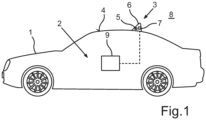
- a schematic illustration of an embodiment of a motor vehicle according to the invention;
- Fig. 2
- a schematic illustration of a camera of an antenna module according to the invention in an exploded representation;
- Fig. 3
- a schematic illustration of an embodiment of an antenna module according to the invention;
- Fig. 4
- a schematic illustration of an antenna module according to
Fig. 3 without the cover of the antenna housing; - Fig. 5
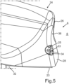
- a schematic illustration of the antenna housing of the antenna module according to
Fig. 3 ; and - Fig. 6
- a further schematic illustration of the antenna module according to
Fig. 3 . - In the figures, identical as well as functionally identical elements are provided with the same reference characters.
-
Fig. 1 shows amotor vehicle 1 according to the present invention. Themotor vehicle 1 is in particular formed as a passenger car. Themotor vehicle 1 includes adriver assistance system 2. Thedriver assistance system 2 includes anantenna module 3, which is disposed on an exterior trim part 4 of themotor vehicle 1. Here, theantenna module 3 is disposed on a roof of themotor vehicle 1. Theantenna module 3 includes at least one antenna 5, which emits and/or receives signals for an infotainment system of themotor vehicle 1. The infotainment system of themotor vehicle 1 can for example be a car radio, a navigation system or the like. - In addition, the
antenna module 3 has anantenna housing 6, which is attached to the exterior trim part 4 for disposing theantenna module 3 on the exterior trim part 4. Here, theantenna housing 6 is formed in the shape of a shark fin. Thus, theantenna module 3 is in particular formed as a shark fin antenna module. The at least one antenna 5 is disposed in an interior of theantenna housing 6. Moreover, theantenna module 3 has acamera 7, which is disposed in the interior of theantenna housing 6 in certain areas. Thecamera 7 is adapted to capture anenvironmental region 8 of themotor vehicle 1 in images. in particular, thecamera 7 captures a rearwardenvironmental region 8 or anenvironmental region 8 behind themotor vehicle 1. The images captured by thecamera 7 can be provided to a control device 9 of thedriver assistance system 2. The control device 9 can for example be formed by a vehicle-side controller. The images captured by thecamera 7 can for example be displayed on a display device of thedriver assistance system 2 not illustrated here in a passenger cabin of themotor vehicle 1. Thus, rearview mirrors of themotor vehicle 1 can be replaced by thedriver assistance system 2 and so-called mirror-less driving can be allowed. Thus, themotor vehicle 1 is in particular formed without rearview mirrors. -
Fig. 2 shows thecamera 7 of theantenna module 3 in an exploded representation. Thecamera 7 includes acamera objective 10 with acamera lens 11 and with anobjective tube 12. Theobjective tube 12 is in particular cylindrically formed, wherein thelens 11 is disposed on the front side on theobjective tube 12. In addition, the objective 10 has a retainingelement 13 as well as acap element 14. In addition, thecamera 7 includes acamera housing 15, which has arear housing 16 as well as afront housing 17. Therear housing 16 is in particular prismatic formed and covered on the front side by thefront housing 17, which is in particular plate-shaped formed. In therear housing 16, electronics here illustrated as acircuit board 18 can be disposed. Thecircuit board 18 can be attached to thefront housing 17 by means of fixingelements 19, for example screws. Thecircuit board 18 can for example have an image sensor and components for image processing of the images captured by the image sensor of thecamera 7. Thefront housing 17 is also referred to as lens housing and serves for retaining thecamera objective 10. Thereto, thefront housing 17 has apassage opening 20, in which thecamera objective 10 can be disposed in certain areas. In particular, the retainingelement 13 is disposed in thepassage opening 20 such that thecap element 14 rests on aborder 21 of thepassage opening 20. Thecap element 14 can be attached to theborder 21 of thepassage opening 20 by means of an adhesive 22 such that the objective 10 is retained on thefront housing 17 and thereby on thecamera housing 15. -
Fig. 3 shows an embodiment of theantenna module 3. Here, theantenna module 3 has aGPS antenna 5a as well as a car-to-car communication antenna 5b as the at least one antenna 5. Theantennas antenna housing 6. Here, theantenna housing 6 has a plate-shapedpedestal 23, on which thecamera 7 and theantennas pedestal 23 can be disposed and attached on the exterior trim part 4. In addition, theantenna housing 6 has a roof-like cover 24, which is here transparently illustrated. The roof-like cover 24 is in particular formed in the shape of a shark fin and forms a radome for theantennas - The
camera housing 15 of thecamera 7 is completely disposed in the interior of theantenna housing 6. Theantenna housing 6 has a passage opening 25 (seeFig. 5 ) in ahousing wall 26, which corresponds to thecamera objective 10. Since thecamera objective 10 is here cylindrically formed, thepassage opening 25 is here formed as a round hole in thehousing wall 26. In thepassage opening 25, the in particularcylindrical camera objective 10 is disposed in certain areas, wherein thelens 11 of thecamera 7 faces theenvironmental region 8 or is formed adjoining to theenvironmental region 8. Therein, an in particular annular gap or a joint arises between thecamera objective 10 and thehousing wall 26 adjoining to thepassage opening 25. In order to prevent for example moisture from theenvironmental region 8 from penetrating into the interior of theantenna housing 26, the gap is sealed. Thereto, a sealingelement 27 is disposed in the gap such that the gap is closed and theantenna housing 6 is thereby sealed. Here, the sealingelement 27 is cylindrically formed and here completely surrounds theobjective tube 12 along an outer circumference of theobjective tube 12. The sealingelement 27 can also extend over an entire length of theobjective tube 12 and thereby completely surround an outer side of theobjective tube 12. The sealingelement 27 is for example manufactured of an elastic material or a polymer, in particular EPDM, and pressed into the gap. Otherwise stated, the sealingelement 27 is radially compressed by theobjective tube 12 and thehousing wall 26 adjoining to thepassage opening 25. - In that the
antenna housing 6 is sealed by means of the sealingelement 27, thecamera housing 15 does not have to be specifically sealed by for example providing a sealing element between therear housing 16 and thefront housing 17. Thus, thefront housing 17 can be formed directly adjoining to therear housing 16. Thefront housing 17 and therear housing 16, thus thecamera housing 15, can be formed of a shielding material, which shields the electronics in thecamera housing 15 from the radiation of theantennas rear housing 16 and thefront housing 17. -
Fig. 4 shows theantenna module 3 without thecover 6 as well as without the sealingelement 27. Thecamera 7 is disposed on thepedestal 23. A bearingsurface 29 is on thepedestal 23, on which theGPS antenna 5a, the car-to-car communication antenna 5b, aradio antenna 5c andcomponents 30 comprising electronics for theantennas surface 29 is here formed as a circuit board, a so-called antenna PCB (PCB- printed circuit board). The bearingsurface 29 is for example connected to thepedestal 23. Thepedestal 23 can be connected to thecover 24 not shown here by means of fixingelements 31, for example by screws. In addition, theantenna module 3 has aninterface 32, via which the antenna PCB as well as thecamera 7 can be connected to the controller of thedriver assistance system 2, for example for transmitting data and/or for energy supply of the antenna PCB as well as thecamera 7. -
Fig. 5 shows theantenna housing 6 with thecover 24 and thepedestal 23. Anouter side 36 of thehousing wall 26 faces theenvironmental region 8 and is formed adjoining to theenvironmental region 8. Thepassage opening 25 is disposed in arear wall 28 of theantenna housing 6. Therear wall 28 of theantenna housing 6 faces the rearwardenvironmental region 8 in an intended installation position of theantenna module 3 on the exterior trim part 4 of themotor vehicle 1 such that thecamera 7 can capture theenvironmental region 8 behind themotor vehicle 1 in images. - The
passage opening 25 is substantially formed as a cylindrical cavity. Thehousing wall 26 bounding thepassage opening 25 has apredetermined wall thickness 33 thereto such that by aninterface 34 between thehousing opening 25 and thehousing wall 26, thus by an inner side of a boundary of the cylindrical cavity, a sealing surface or a sealing area for the sealingelement 27 is formed. Thereto, thehousing wall 26 can for example only be reinforced in the area adjoining to thepassage opening 25. Therein, the sealingelement 27 in particular has a length, which at least corresponds to thewall thickness 33 such that an outer side 35 (seeFig. 3 ) of the sealingelement 27 forms a particularly large-area overlap area with theinterface 34. -
Fig. 6 shows anantenna module 3 with theantenna housing 6 and thecamera 7, wherein the at least one antenna 5 is completely disposed in the interior not visible here and thecamera 7 is disposed in the interior in certain areas. Thus, only theouter side 36 of thehousing wall 26, thelens 11 of thecamera 7 as well as a front side of the sealingelement 27 of theantenna module 3 are visible. Theouter side 36 of thehousing wall 26, thelens 11 of thecamera 7 as well as the front side of the sealingelement 27 are in particular flush arranged. In addition, it is shown that theantenna housing 6 is formed in the shape of a shark fin. Therein,curved sidewalls 37 of thecover 24 of theantenna housing 6 form aridge 38 on a top side of theantenna module 3 starting from thepedestal 23. Therear wall 28 of thecover 24 is also formed adjoining to theridge 38 starting from thepedestal 23.
Claims (12)
- Antenna module (3) for a motor vehicle (1) comprising at least one antenna (5, 5a, 5b, 5c) for an infotainment system of the motor vehicle (1), an antenna housing (6) for attaching to an exterior trim part (4) of the motor vehicle (1) and a camera (7) with a camera objective (10) for capturing an environmental region (8) of the motor vehicle (1), wherein the at least one antenna (5, 5a, 5b, 5c) is disposed in an interior of the antenna housing (6),
andone of the at least one antenna being a car-to-car communication antenna (5b) and the camera (7) is disposed in the interior of the antenna housing (6) in certain areas, wherein the camera objective (10) is disposed in a passage opening (25) of a housing wall (26) of the antenna housing (6) corresponding to the camera objective (10) at least in certain areas, and the antenna module (3) comprises a sealing element (27) for sealing a gap between the housing wall (26) adjoining to the passage opening (25) and the camera objective (10) while the sealing element (27) is hollow cylindrically formedwhereby the camera (7) comprises a camera housing (15) with a rear housing (16) for electronics (18) of the camera (7) and a front housing (17) for retaining the camera objective (10), wherein the camera housing (15) is disposed in the interior of the antenna housing (6) and comprises a shielding material for shielding the electronics of the camera (7) from radiation of the at least one antenna (5, 5a, 5b, 5c). - Antenna module (3) according to claim 1,
characterized in that
the sealing element (27) comprises an elastic material and is pressed into the gap between the housing wall (26) adjoining to the passage opening (25) and the camera objective (10). - Antenna module (3) according to claim 1 or 2,
characterized in that
the sealing element (27) comprises ethylene propylene diene rubber as the elastic material. - Antenna module (3) according to claim 1,
characterized in that
an objective tube (12) of the camera objective (10) is disposed within the hollow cylindrical sealing element (27), wherein the hollow cylindrical sealing element (27) covers the objective tube (12) along a length of the objective tube (12) at least in certain areas. - Antenna module (3) according to claim 4,
characterized in that
the housing wall (26) has a predetermined wall thickness (33) at least in an area of the housing wall (26) adjoining to the passage opening (25) such that the passage opening (25) is formed as a cylindrical cavity, and a length of the hollow cylindrical sealing element (27) corresponds at least to the predetermined wall thickness (33) of the housing wall (26). - Antenna module (3) according to any one of the preceding claims,
characterized in that
a lens (11) disposed on a front side of the camera objective (10), a front side of the sealing element (27) and an outer side (36) of the housing wall (26) of the antenna housing (6) are substantially flush disposed. - Antenna module (3) according to any one of the preceding claims,
characterized in that
the antenna housing (6) comprises a plate-shaped pedestal (23) for disposing on the exterior trim part (4) and a roof-shaped cover (24) covering the pedestal (23), wherein the passage opening (25) is formed in a rear wall (28) of the cover (24). - Antenna module (3) according to any one of the preceding claims,
characterized in that
the antenna module (3) is formed as a shark fin antenna module. - Driver assistance system (2) for a motor vehicle (1), with an antenna module (3) according to any one of the preceding claims.
- Motor vehicle (1) with a driver assistance system (2) according to claim 9.
- Motor vehicle (1) according to claim 10,
characterized in that
the motor vehicle (1) is formed without rearview mirrors. - Motor vehicle (1) according to claim 10 or 11,
characterized in that
the antenna module (3) is disposed on a roof (4) of the motor vehicle (1).
Applications Claiming Priority (2)
| Application Number | Priority Date | Filing Date | Title |
|---|---|---|---|
| DE102016100985.7A DE102016100985A1 (en) | 2016-01-21 | 2016-01-21 | Antenna module for a motor vehicle, driver assistance system and motor vehicle |
| PCT/EP2017/051192 WO2017125552A1 (en) | 2016-01-21 | 2017-01-20 | Antenna module for a motor vehicle, driver assistance system as well as motor vehicle |
Publications (2)
| Publication Number | Publication Date |
|---|---|
| EP3405992A1 EP3405992A1 (en) | 2018-11-28 |
| EP3405992B1 true EP3405992B1 (en) | 2024-07-10 |
Family
ID=57909604
Family Applications (1)
| Application Number | Title | Priority Date | Filing Date |
|---|---|---|---|
| EP17701831.4A Active EP3405992B1 (en) | 2016-01-21 | 2017-01-20 | Antenna module for a motor vehicle, driver assistance system as well as motor vehicle |
Country Status (4)
| Country | Link |
|---|---|
| US (1) | US10707567B2 (en) |
| EP (1) | EP3405992B1 (en) |
| DE (1) | DE102016100985A1 (en) |
| WO (1) | WO2017125552A1 (en) |
Families Citing this family (14)
| Publication number | Priority date | Publication date | Assignee | Title |
|---|---|---|---|---|
| JP6567679B2 (en) * | 2015-09-14 | 2019-08-28 | 株式会社ヨコオ | Antenna device |
| US10340587B2 (en) * | 2016-09-13 | 2019-07-02 | Laird Technologies, Inc. | Antenna assemblies having sealed cameras |
| US10374297B2 (en) | 2017-09-12 | 2019-08-06 | Laird Technologies, Inc. | Antenna assemblies having sealed cameras |
| WO2019156138A1 (en) * | 2018-02-08 | 2019-08-15 | 株式会社ヨコオ | Vehicle-mounted antenna device |
| JP7227231B2 (en) * | 2018-04-27 | 2023-02-21 | 株式会社ヨコオ | In-vehicle antenna device |
| FR3086750B1 (en) * | 2018-09-28 | 2020-11-13 | Valeo Systemes Dessuyage | AUTOMOTIVE VEHICLE GEOLOCATION DEVICE |
| NL2022163B1 (en) * | 2018-12-10 | 2020-07-02 | Daf Trucks Nv | Wireless vehicle to vehicle communication system for mounting on a vehicle |
| DE102019214632B4 (en) * | 2019-09-25 | 2021-07-29 | Zf Friedrichshafen Ag | Camera carrier for attachment to a vehicle and method for manufacturing and operating a camera carrier |
| JP6802895B1 (en) * | 2019-10-17 | 2020-12-23 | 原田工業株式会社 | Vehicle exterior equipment |
| RU204346U1 (en) * | 2020-07-30 | 2021-05-21 | Общество с ограниченной ответственностью "Эй Ви Эй Системс" | External antenna module with extended functionality |
| CN213705325U (en) * | 2020-11-17 | 2021-07-16 | 本田技研工业株式会社 | Sensor bracket structure |
| DE102022105422A1 (en) * | 2022-03-08 | 2023-09-14 | Connaught Electronics Ltd. | Vehicle camera with improved housing alignment |
| EP4269177A1 (en) * | 2022-04-27 | 2023-11-01 | Grupo Antolin-Ingenieria, S.A. | Vehicle trim with camera for vehicles |
| CN115764247A (en) * | 2022-05-06 | 2023-03-07 | 惠州市德赛西威汽车电子股份有限公司 | A Shark Fin Antenna with Integrated Camera Device |
Citations (3)
| Publication number | Priority date | Publication date | Assignee | Title |
|---|---|---|---|---|
| KR20120000680U (en) * | 2011-10-20 | 2012-02-01 | (주)아이머큐리 | Car video camera |
| KR101251979B1 (en) * | 2012-09-05 | 2013-04-08 | 주식회사 경오전자 | Black box rear camera with dmb antenna for vehicle |
| US20140158731A1 (en) * | 2012-12-10 | 2014-06-12 | Michael J. Squire | Vehicle camera mounting assembly |
Family Cites Families (31)
| Publication number | Priority date | Publication date | Assignee | Title |
|---|---|---|---|---|
| US5793420A (en) * | 1994-10-28 | 1998-08-11 | Schmidt; William P. | Video recording system for vehicle |
| US7965336B2 (en) * | 2002-11-14 | 2011-06-21 | Donnelly Corporation | Imaging system for vehicle |
| US7057500B1 (en) * | 2004-04-23 | 2006-06-06 | Belloso Gregorio M | Rear view monitoring system for motor vehicles |
| DE102005027089B4 (en) * | 2005-06-11 | 2013-03-21 | Daimler Ag | Profile for receiving a sensor tape on a vehicle bumper and bumper |
| JP4497193B2 (en) * | 2007-11-09 | 2010-07-07 | ソニー株式会社 | Camera mounting structure, camera mounting method, and vehicle exterior panel component |
| US20100129070A1 (en) * | 2008-11-21 | 2010-05-27 | Nissan Technical Center North America, Inc. | Rear view camera mounting on a vehicle |
| KR20110004565A (en) * | 2009-07-08 | 2011-01-14 | 엘지전자 주식회사 | Humidification member and humidification unit having the same |
| KR200455494Y1 (en) * | 2009-10-30 | 2011-09-08 | 조부연 | Shark antenna consisting of one or more camera modules |
| KR101134305B1 (en) * | 2010-04-12 | 2012-04-09 | (주)헤스코 | Car camera built in shark antenna |
| JP5755015B2 (en) * | 2010-06-06 | 2015-07-29 | 日東電工株式会社 | EPDM foam and adhesive sealing material |
| DE102010064080A1 (en) | 2010-12-23 | 2012-06-28 | Robert Bosch Gmbh | Driver assistance system for vehicle e.g. passenger car, has camera that is integrated in roof antenna of vehicle, which is backup camera |
| WO2012138455A1 (en) * | 2011-03-10 | 2012-10-11 | Bowles Fluidics Corporation | Integrated automotive system, nozzle assembly and remote control method for cleaning an image sensor's lens |
| KR101052796B1 (en) * | 2011-03-18 | 2011-07-29 | 박상옥 | Car Antenna with Camera |
| US9838653B2 (en) * | 2011-06-24 | 2017-12-05 | Gentex Corporation | Roof mounted imager module |
| US9871971B2 (en) * | 2011-08-02 | 2018-01-16 | Magma Electronics Inc. | Vehicle vision system with light baffling system |
| KR101155607B1 (en) * | 2011-11-14 | 2012-06-13 | 최현준 | Vehicle antenna with built-in camera |
| US9849836B2 (en) * | 2014-04-24 | 2017-12-26 | Gentex Corporation | Roof mounted imager module |
| KR101886204B1 (en) * | 2014-12-31 | 2018-08-08 | 젠텍스 코포레이션 | Rear vehicle camera |
| CN104979631A (en) * | 2015-05-27 | 2015-10-14 | 泰州苏中天线集团有限公司 | Shark fin type antenna provided with image camera devices |
| DE102015210449B4 (en) * | 2015-06-08 | 2017-06-01 | Continental Teves Ag & Co. Ohg | Arrangement of a camera in the rear of a vehicle, camera, roof antenna and vehicle |
| US9985343B2 (en) * | 2015-07-29 | 2018-05-29 | GM Global Technology Operations LLC | Optimal camera and antenna integration |
| WO2017046972A1 (en) * | 2015-09-14 | 2017-03-23 | 株式会社ヨコオ | Onboard antenna device |
| JP6567679B2 (en) * | 2015-09-14 | 2019-08-28 | 株式会社ヨコオ | Antenna device |
| US10351072B2 (en) * | 2015-11-05 | 2019-07-16 | Magna Electronics Inc. | Vehicle camera with modular construction |
| US10618474B2 (en) * | 2015-11-12 | 2020-04-14 | Connaught Electronics Ltd. | Sharkfin rf and camera integration |
| US9674414B1 (en) * | 2015-12-02 | 2017-06-06 | Bendix Commercial Vehicle Systems Llc | Camera module having compact camera subassembly insertable into the camera housing |
| KR102145985B1 (en) * | 2016-03-04 | 2020-08-19 | 젠텍스 코포레이션 | Roof Mount Imager Module |
| US10340587B2 (en) * | 2016-09-13 | 2019-07-02 | Laird Technologies, Inc. | Antenna assemblies having sealed cameras |
| JP6486314B2 (en) * | 2016-10-28 | 2019-03-20 | 原田工業株式会社 | In-vehicle antenna device |
| WO2018183517A1 (en) * | 2017-03-30 | 2018-10-04 | Gentex Corporation | Switchable imager lens cover |
| JP2019142401A (en) * | 2018-02-22 | 2019-08-29 | 株式会社デンソー | On-vehicle camera |
-
2016
- 2016-01-21 DE DE102016100985.7A patent/DE102016100985A1/en not_active Withdrawn
-
2017
- 2017-01-20 WO PCT/EP2017/051192 patent/WO2017125552A1/en not_active Ceased
- 2017-01-20 EP EP17701831.4A patent/EP3405992B1/en active Active
- 2017-01-20 US US15/411,011 patent/US10707567B2/en active Active
Patent Citations (3)
| Publication number | Priority date | Publication date | Assignee | Title |
|---|---|---|---|---|
| KR20120000680U (en) * | 2011-10-20 | 2012-02-01 | (주)아이머큐리 | Car video camera |
| KR101251979B1 (en) * | 2012-09-05 | 2013-04-08 | 주식회사 경오전자 | Black box rear camera with dmb antenna for vehicle |
| US20140158731A1 (en) * | 2012-12-10 | 2014-06-12 | Michael J. Squire | Vehicle camera mounting assembly |
Non-Patent Citations (1)
| Title |
|---|
| ANONYMOUS: "Power steering - Wikipedia", 13 May 2014 (2014-05-13), XP055448325, Retrieved from the Internet <URL:https://en.wikipedia.org/w/index.php?title=Power_steering&oldid=608342086> [retrieved on 20180206] * |
Also Published As
| Publication number | Publication date |
|---|---|
| WO2017125552A1 (en) | 2017-07-27 |
| US10707567B2 (en) | 2020-07-07 |
| EP3405992A1 (en) | 2018-11-28 |
| US20170214130A1 (en) | 2017-07-27 |
| DE102016100985A1 (en) | 2017-07-27 |
Similar Documents
| Publication | Publication Date | Title |
|---|---|---|
| US10707567B2 (en) | Antenna module for a motor vehicle, driver assistance system as well as motor vehicle | |
| US10073163B2 (en) | Control device | |
| JP6883634B2 (en) | In-vehicle antenna device | |
| US10033934B2 (en) | Vehicle vision system with exterior viewing camera | |
| CN1284273C (en) | Aerial installing structure for motor-driven two-wheel motorcycle | |
| US20180249126A1 (en) | Indicia and camera assembly for a vehicle | |
| KR101498804B1 (en) | Mirror replacement system for a vehicle | |
| US20180037171A1 (en) | Concealed mounting for autonomous vehicle sensor | |
| KR101778173B1 (en) | A rearview assembly of a vehicle for displaying images | |
| CN106255618A (en) | There is the motor vehicles of the rear-view mirror device without rearview mirror | |
| WO2013123161A1 (en) | Vehicle vision system with light baffling system | |
| CN112533795B (en) | Holding device for holding a sensor unit and an arrangement system for the holding device | |
| CN105774678A (en) | Variable structural-member covering | |
| US20200366821A1 (en) | Roof Antenna Of A Vehicle Having A Reversing Camera | |
| JP2017073751A (en) | On-vehicle camera and vehicle | |
| CN113382889A (en) | Structural unit for arrangement in the front or rear end of a motor vehicle | |
| CN110297245A (en) | Device with sensor module and hood | |
| CN111083319A (en) | Camera device | |
| JP4718243B2 (en) | Connector unit, in-vehicle digital camera, door mirror with in-vehicle camera | |
| US10596979B2 (en) | Device for capturing optical information | |
| WO2017125477A1 (en) | Antenna module for a motor vehicle, driver assistance system as well as motor vehicle | |
| US20160129838A1 (en) | Wide angle rear and side view monitor | |
| US20080278581A1 (en) | Vehicle-Mounted Camera System | |
| US20190179215A1 (en) | Camera for a motor vehicle, comprising an integrally formed housing top part and a lens carrier, as well as motor vehicle and method for manufacturing a camera for a motor vehicle | |
| JP6455357B2 (en) | Mounting structure for in-vehicle equipment |
Legal Events
| Date | Code | Title | Description |
|---|---|---|---|
| STAA | Information on the status of an ep patent application or granted ep patent |
Free format text: STATUS: UNKNOWN |
|
| STAA | Information on the status of an ep patent application or granted ep patent |
Free format text: STATUS: THE INTERNATIONAL PUBLICATION HAS BEEN MADE |
|
| PUAI | Public reference made under article 153(3) epc to a published international application that has entered the european phase |
Free format text: ORIGINAL CODE: 0009012 |
|
| STAA | Information on the status of an ep patent application or granted ep patent |
Free format text: STATUS: REQUEST FOR EXAMINATION WAS MADE |
|
| 17P | Request for examination filed |
Effective date: 20180625 |
|
| AK | Designated contracting states |
Kind code of ref document: A1 Designated state(s): AL AT BE BG CH CY CZ DE DK EE ES FI FR GB GR HR HU IE IS IT LI LT LU LV MC MK MT NL NO PL PT RO RS SE SI SK SM TR |
|
| AX | Request for extension of the european patent |
Extension state: BA ME |
|
| RIN1 | Information on inventor provided before grant (corrected) |
Inventor name: GRIMES, CAROL Inventor name: HEHIR, COLIN PATRICK |
|
| DAV | Request for validation of the european patent (deleted) | ||
| DAX | Request for extension of the european patent (deleted) | ||
| STAA | Information on the status of an ep patent application or granted ep patent |
Free format text: STATUS: EXAMINATION IS IN PROGRESS |
|
| 17Q | First examination report despatched |
Effective date: 20200218 |
|
| P01 | Opt-out of the competence of the unified patent court (upc) registered |
Effective date: 20230528 |
|
| GRAP | Despatch of communication of intention to grant a patent |
Free format text: ORIGINAL CODE: EPIDOSNIGR1 |
|
| STAA | Information on the status of an ep patent application or granted ep patent |
Free format text: STATUS: GRANT OF PATENT IS INTENDED |
|
| RIC1 | Information provided on ipc code assigned before grant |
Ipc: B60R 11/00 20060101ALN20240115BHEP Ipc: H01Q 1/42 20060101ALN20240115BHEP Ipc: B60R 11/04 20060101ALI20240115BHEP Ipc: H01Q 1/32 20060101ALI20240115BHEP Ipc: H01Q 1/12 20060101AFI20240115BHEP |
|
| INTG | Intention to grant announced |
Effective date: 20240206 |
|
| GRAS | Grant fee paid |
Free format text: ORIGINAL CODE: EPIDOSNIGR3 |
|
| GRAA | (expected) grant |
Free format text: ORIGINAL CODE: 0009210 |
|
| STAA | Information on the status of an ep patent application or granted ep patent |
Free format text: STATUS: THE PATENT HAS BEEN GRANTED |
|
| AK | Designated contracting states |
Kind code of ref document: B1 Designated state(s): AL AT BE BG CH CY CZ DE DK EE ES FI FR GB GR HR HU IE IS IT LI LT LU LV MC MK MT NL NO PL PT RO RS SE SI SK SM TR |
|
| REG | Reference to a national code |
Ref country code: CH Ref legal event code: EP |
|
| REG | Reference to a national code |
Ref country code: DE Ref legal event code: R096 Ref document number: 602017083163 Country of ref document: DE |
|
| REG | Reference to a national code |
Ref country code: LT Ref legal event code: MG9D |
|
| REG | Reference to a national code |
Ref country code: NL Ref legal event code: MP Effective date: 20240710 |
|
| PG25 | Lapsed in a contracting state [announced via postgrant information from national office to epo] |
Ref country code: PT Free format text: LAPSE BECAUSE OF FAILURE TO SUBMIT A TRANSLATION OF THE DESCRIPTION OR TO PAY THE FEE WITHIN THE PRESCRIBED TIME-LIMIT Effective date: 20241111 |
|
| REG | Reference to a national code |
Ref country code: AT Ref legal event code: MK05 Ref document number: 1702868 Country of ref document: AT Kind code of ref document: T Effective date: 20240710 |
|
| PG25 | Lapsed in a contracting state [announced via postgrant information from national office to epo] |
Ref country code: NL Free format text: LAPSE BECAUSE OF FAILURE TO SUBMIT A TRANSLATION OF THE DESCRIPTION OR TO PAY THE FEE WITHIN THE PRESCRIBED TIME-LIMIT Effective date: 20240710 |
|
| PG25 | Lapsed in a contracting state [announced via postgrant information from national office to epo] |
Ref country code: PT Free format text: LAPSE BECAUSE OF FAILURE TO SUBMIT A TRANSLATION OF THE DESCRIPTION OR TO PAY THE FEE WITHIN THE PRESCRIBED TIME-LIMIT Effective date: 20241111 Ref country code: NL Free format text: LAPSE BECAUSE OF FAILURE TO SUBMIT A TRANSLATION OF THE DESCRIPTION OR TO PAY THE FEE WITHIN THE PRESCRIBED TIME-LIMIT Effective date: 20240710 |
|
| PG25 | Lapsed in a contracting state [announced via postgrant information from national office to epo] |
Ref country code: NO Free format text: LAPSE BECAUSE OF FAILURE TO SUBMIT A TRANSLATION OF THE DESCRIPTION OR TO PAY THE FEE WITHIN THE PRESCRIBED TIME-LIMIT Effective date: 20241010 |
|
| PG25 | Lapsed in a contracting state [announced via postgrant information from national office to epo] |
Ref country code: GR Free format text: LAPSE BECAUSE OF FAILURE TO SUBMIT A TRANSLATION OF THE DESCRIPTION OR TO PAY THE FEE WITHIN THE PRESCRIBED TIME-LIMIT Effective date: 20241011 Ref country code: PL Free format text: LAPSE BECAUSE OF FAILURE TO SUBMIT A TRANSLATION OF THE DESCRIPTION OR TO PAY THE FEE WITHIN THE PRESCRIBED TIME-LIMIT Effective date: 20240710 Ref country code: FI Free format text: LAPSE BECAUSE OF FAILURE TO SUBMIT A TRANSLATION OF THE DESCRIPTION OR TO PAY THE FEE WITHIN THE PRESCRIBED TIME-LIMIT Effective date: 20240710 |
|
| PG25 | Lapsed in a contracting state [announced via postgrant information from national office to epo] |
Ref country code: BG Free format text: LAPSE BECAUSE OF FAILURE TO SUBMIT A TRANSLATION OF THE DESCRIPTION OR TO PAY THE FEE WITHIN THE PRESCRIBED TIME-LIMIT Effective date: 20240710 |
|
| PG25 | Lapsed in a contracting state [announced via postgrant information from national office to epo] |
Ref country code: LV Free format text: LAPSE BECAUSE OF FAILURE TO SUBMIT A TRANSLATION OF THE DESCRIPTION OR TO PAY THE FEE WITHIN THE PRESCRIBED TIME-LIMIT Effective date: 20240710 |
|
| PG25 | Lapsed in a contracting state [announced via postgrant information from national office to epo] |
Ref country code: IS Free format text: LAPSE BECAUSE OF FAILURE TO SUBMIT A TRANSLATION OF THE DESCRIPTION OR TO PAY THE FEE WITHIN THE PRESCRIBED TIME-LIMIT Effective date: 20241110 Ref country code: AT Free format text: LAPSE BECAUSE OF FAILURE TO SUBMIT A TRANSLATION OF THE DESCRIPTION OR TO PAY THE FEE WITHIN THE PRESCRIBED TIME-LIMIT Effective date: 20240710 |
|
| PG25 | Lapsed in a contracting state [announced via postgrant information from national office to epo] |
Ref country code: HR Free format text: LAPSE BECAUSE OF FAILURE TO SUBMIT A TRANSLATION OF THE DESCRIPTION OR TO PAY THE FEE WITHIN THE PRESCRIBED TIME-LIMIT Effective date: 20240710 |
|
| PG25 | Lapsed in a contracting state [announced via postgrant information from national office to epo] |
Ref country code: ES Free format text: LAPSE BECAUSE OF FAILURE TO SUBMIT A TRANSLATION OF THE DESCRIPTION OR TO PAY THE FEE WITHIN THE PRESCRIBED TIME-LIMIT Effective date: 20240710 Ref country code: RS Free format text: LAPSE BECAUSE OF FAILURE TO SUBMIT A TRANSLATION OF THE DESCRIPTION OR TO PAY THE FEE WITHIN THE PRESCRIBED TIME-LIMIT Effective date: 20241010 |
|
| PG25 | Lapsed in a contracting state [announced via postgrant information from national office to epo] |
Ref country code: RS Free format text: LAPSE BECAUSE OF FAILURE TO SUBMIT A TRANSLATION OF THE DESCRIPTION OR TO PAY THE FEE WITHIN THE PRESCRIBED TIME-LIMIT Effective date: 20241010 Ref country code: PL Free format text: LAPSE BECAUSE OF FAILURE TO SUBMIT A TRANSLATION OF THE DESCRIPTION OR TO PAY THE FEE WITHIN THE PRESCRIBED TIME-LIMIT Effective date: 20240710 Ref country code: NO Free format text: LAPSE BECAUSE OF FAILURE TO SUBMIT A TRANSLATION OF THE DESCRIPTION OR TO PAY THE FEE WITHIN THE PRESCRIBED TIME-LIMIT Effective date: 20241010 Ref country code: LV Free format text: LAPSE BECAUSE OF FAILURE TO SUBMIT A TRANSLATION OF THE DESCRIPTION OR TO PAY THE FEE WITHIN THE PRESCRIBED TIME-LIMIT Effective date: 20240710 Ref country code: IS Free format text: LAPSE BECAUSE OF FAILURE TO SUBMIT A TRANSLATION OF THE DESCRIPTION OR TO PAY THE FEE WITHIN THE PRESCRIBED TIME-LIMIT Effective date: 20241110 Ref country code: HR Free format text: LAPSE BECAUSE OF FAILURE TO SUBMIT A TRANSLATION OF THE DESCRIPTION OR TO PAY THE FEE WITHIN THE PRESCRIBED TIME-LIMIT Effective date: 20240710 Ref country code: GR Free format text: LAPSE BECAUSE OF FAILURE TO SUBMIT A TRANSLATION OF THE DESCRIPTION OR TO PAY THE FEE WITHIN THE PRESCRIBED TIME-LIMIT Effective date: 20241011 Ref country code: FI Free format text: LAPSE BECAUSE OF FAILURE TO SUBMIT A TRANSLATION OF THE DESCRIPTION OR TO PAY THE FEE WITHIN THE PRESCRIBED TIME-LIMIT Effective date: 20240710 Ref country code: ES Free format text: LAPSE BECAUSE OF FAILURE TO SUBMIT A TRANSLATION OF THE DESCRIPTION OR TO PAY THE FEE WITHIN THE PRESCRIBED TIME-LIMIT Effective date: 20240710 Ref country code: BG Free format text: LAPSE BECAUSE OF FAILURE TO SUBMIT A TRANSLATION OF THE DESCRIPTION OR TO PAY THE FEE WITHIN THE PRESCRIBED TIME-LIMIT Effective date: 20240710 Ref country code: AT Free format text: LAPSE BECAUSE OF FAILURE TO SUBMIT A TRANSLATION OF THE DESCRIPTION OR TO PAY THE FEE WITHIN THE PRESCRIBED TIME-LIMIT Effective date: 20240710 |
|
| REG | Reference to a national code |
Ref country code: DE Ref legal event code: R097 Ref document number: 602017083163 Country of ref document: DE |
|
| PG25 | Lapsed in a contracting state [announced via postgrant information from national office to epo] |
Ref country code: DK Free format text: LAPSE BECAUSE OF FAILURE TO SUBMIT A TRANSLATION OF THE DESCRIPTION OR TO PAY THE FEE WITHIN THE PRESCRIBED TIME-LIMIT Effective date: 20240710 Ref country code: SM Free format text: LAPSE BECAUSE OF FAILURE TO SUBMIT A TRANSLATION OF THE DESCRIPTION OR TO PAY THE FEE WITHIN THE PRESCRIBED TIME-LIMIT Effective date: 20240710 Ref country code: RO Free format text: LAPSE BECAUSE OF FAILURE TO SUBMIT A TRANSLATION OF THE DESCRIPTION OR TO PAY THE FEE WITHIN THE PRESCRIBED TIME-LIMIT Effective date: 20240710 |
|
| PG25 | Lapsed in a contracting state [announced via postgrant information from national office to epo] |
Ref country code: EE Free format text: LAPSE BECAUSE OF FAILURE TO SUBMIT A TRANSLATION OF THE DESCRIPTION OR TO PAY THE FEE WITHIN THE PRESCRIBED TIME-LIMIT Effective date: 20240710 |
|
| PG25 | Lapsed in a contracting state [announced via postgrant information from national office to epo] |
Ref country code: CZ Free format text: LAPSE BECAUSE OF FAILURE TO SUBMIT A TRANSLATION OF THE DESCRIPTION OR TO PAY THE FEE WITHIN THE PRESCRIBED TIME-LIMIT Effective date: 20240710 |
|
| PG25 | Lapsed in a contracting state [announced via postgrant information from national office to epo] |
Ref country code: IT Free format text: LAPSE BECAUSE OF FAILURE TO SUBMIT A TRANSLATION OF THE DESCRIPTION OR TO PAY THE FEE WITHIN THE PRESCRIBED TIME-LIMIT Effective date: 20240710 Ref country code: SK Free format text: LAPSE BECAUSE OF FAILURE TO SUBMIT A TRANSLATION OF THE DESCRIPTION OR TO PAY THE FEE WITHIN THE PRESCRIBED TIME-LIMIT Effective date: 20240710 |
|
| PLBE | No opposition filed within time limit |
Free format text: ORIGINAL CODE: 0009261 |
|
| STAA | Information on the status of an ep patent application or granted ep patent |
Free format text: STATUS: NO OPPOSITION FILED WITHIN TIME LIMIT |
|
| 26N | No opposition filed |
Effective date: 20250411 |
|
| REG | Reference to a national code |
Ref country code: CH Ref legal event code: PL |
|
| PG25 | Lapsed in a contracting state [announced via postgrant information from national office to epo] |
Ref country code: SE Free format text: LAPSE BECAUSE OF FAILURE TO SUBMIT A TRANSLATION OF THE DESCRIPTION OR TO PAY THE FEE WITHIN THE PRESCRIBED TIME-LIMIT Effective date: 20240710 |
|
| PG25 | Lapsed in a contracting state [announced via postgrant information from national office to epo] |
Ref country code: LU Free format text: LAPSE BECAUSE OF NON-PAYMENT OF DUE FEES Effective date: 20250120 Ref country code: MC Free format text: LAPSE BECAUSE OF FAILURE TO SUBMIT A TRANSLATION OF THE DESCRIPTION OR TO PAY THE FEE WITHIN THE PRESCRIBED TIME-LIMIT Effective date: 20240710 |
|
| PG25 | Lapsed in a contracting state [announced via postgrant information from national office to epo] |
Ref country code: BE Free format text: LAPSE BECAUSE OF NON-PAYMENT OF DUE FEES Effective date: 20250131 |
|
| PG25 | Lapsed in a contracting state [announced via postgrant information from national office to epo] |
Ref country code: CH Free format text: LAPSE BECAUSE OF NON-PAYMENT OF DUE FEES Effective date: 20250131 |
|
| REG | Reference to a national code |
Ref country code: BE Ref legal event code: MM Effective date: 20250131 |
|
| PG25 | Lapsed in a contracting state [announced via postgrant information from national office to epo] |
Ref country code: IE Free format text: LAPSE BECAUSE OF NON-PAYMENT OF DUE FEES Effective date: 20250120 |
|
| PGFP | Annual fee paid to national office [announced via postgrant information from national office to epo] |
Ref country code: GB Payment date: 20260127 Year of fee payment: 10 |
|
| PGFP | Annual fee paid to national office [announced via postgrant information from national office to epo] |
Ref country code: DE Payment date: 20260114 Year of fee payment: 10 |
|
| PGFP | Annual fee paid to national office [announced via postgrant information from national office to epo] |
Ref country code: FR Payment date: 20260128 Year of fee payment: 10 |