EP3405962B1 - Vorrichtung zur erzeugung, übertragung, verteilung und/oder verwendung elektrischer energie oder eine komponente einer solchen vorrichtung sowie gasdichtung für eine solche vorrichtung oder komponente - Google Patents
Vorrichtung zur erzeugung, übertragung, verteilung und/oder verwendung elektrischer energie oder eine komponente einer solchen vorrichtung sowie gasdichtung für eine solche vorrichtung oder komponente Download PDFInfo
- Publication number
- EP3405962B1 EP3405962B1 EP17702547.5A EP17702547A EP3405962B1 EP 3405962 B1 EP3405962 B1 EP 3405962B1 EP 17702547 A EP17702547 A EP 17702547A EP 3405962 B1 EP3405962 B1 EP 3405962B1
- Authority
- EP
- European Patent Office
- Prior art keywords
- gas seal
- butyl rubber
- gas
- component
- component according
- Prior art date
- Legal status (The legal status is an assumption and is not a legal conclusion. Google has not performed a legal analysis and makes no representation as to the accuracy of the status listed.)
- Revoked
Links
Images

Classifications
-
- H—ELECTRICITY
- H02—GENERATION; CONVERSION OR DISTRIBUTION OF ELECTRIC POWER
- H02B—BOARDS, SUBSTATIONS OR SWITCHING ARRANGEMENTS FOR THE SUPPLY OR DISTRIBUTION OF ELECTRIC POWER
- H02B13/00—Arrangement of switchgear in which switches are enclosed in, or structurally associated with, a casing, e.g. cubicle
- H02B13/02—Arrangement of switchgear in which switches are enclosed in, or structurally associated with, a casing, e.g. cubicle with metal casing
- H02B13/035—Gas-insulated switchgear
- H02B13/045—Details of casing, e.g. gas tightness
-
- C—CHEMISTRY; METALLURGY
- C08—ORGANIC MACROMOLECULAR COMPOUNDS; THEIR PREPARATION OR CHEMICAL WORKING-UP; COMPOSITIONS BASED THEREON
- C08F—MACROMOLECULAR COMPOUNDS OBTAINED BY REACTIONS ONLY INVOLVING CARBON-TO-CARBON UNSATURATED BONDS
- C08F210/00—Copolymers of unsaturated aliphatic hydrocarbons having only one carbon-to-carbon double bond
- C08F210/04—Monomers containing three or four carbon atoms
- C08F210/08—Butenes
- C08F210/10—Isobutene
- C08F210/12—Isobutene with conjugated diolefins, e.g. butyl rubber
-
- C—CHEMISTRY; METALLURGY
- C09—DYES; PAINTS; POLISHES; NATURAL RESINS; ADHESIVES; COMPOSITIONS NOT OTHERWISE PROVIDED FOR; APPLICATIONS OF MATERIALS NOT OTHERWISE PROVIDED FOR
- C09K—MATERIALS FOR MISCELLANEOUS APPLICATIONS, NOT PROVIDED FOR ELSEWHERE
- C09K3/00—Materials not provided for elsewhere
- C09K3/10—Materials in mouldable or extrudable form for sealing or packing joints or covers
-
- H—ELECTRICITY
- H01—ELECTRIC ELEMENTS
- H01B—CABLES; CONDUCTORS; INSULATORS; SELECTION OF MATERIALS FOR THEIR CONDUCTIVE, INSULATING OR DIELECTRIC PROPERTIES
- H01B3/00—Insulators or insulating bodies characterised by the insulating materials; Selection of materials for their insulating or dielectric properties
- H01B3/18—Insulators or insulating bodies characterised by the insulating materials; Selection of materials for their insulating or dielectric properties mainly consisting of organic substances
- H01B3/20—Insulators or insulating bodies characterised by the insulating materials; Selection of materials for their insulating or dielectric properties mainly consisting of organic substances liquids, e.g. oils
- H01B3/24—Insulators or insulating bodies characterised by the insulating materials; Selection of materials for their insulating or dielectric properties mainly consisting of organic substances liquids, e.g. oils containing halogen in the molecules, e.g. halogenated oils
-
- H—ELECTRICITY
- H01—ELECTRIC ELEMENTS
- H01B—CABLES; CONDUCTORS; INSULATORS; SELECTION OF MATERIALS FOR THEIR CONDUCTIVE, INSULATING OR DIELECTRIC PROPERTIES
- H01B3/00—Insulators or insulating bodies characterised by the insulating materials; Selection of materials for their insulating or dielectric properties
- H01B3/18—Insulators or insulating bodies characterised by the insulating materials; Selection of materials for their insulating or dielectric properties mainly consisting of organic substances
- H01B3/28—Insulators or insulating bodies characterised by the insulating materials; Selection of materials for their insulating or dielectric properties mainly consisting of organic substances natural or synthetic rubbers
-
- H—ELECTRICITY
- H01—ELECTRIC ELEMENTS
- H01B—CABLES; CONDUCTORS; INSULATORS; SELECTION OF MATERIALS FOR THEIR CONDUCTIVE, INSULATING OR DIELECTRIC PROPERTIES
- H01B3/00—Insulators or insulating bodies characterised by the insulating materials; Selection of materials for their insulating or dielectric properties
- H01B3/18—Insulators or insulating bodies characterised by the insulating materials; Selection of materials for their insulating or dielectric properties mainly consisting of organic substances
- H01B3/56—Insulators or insulating bodies characterised by the insulating materials; Selection of materials for their insulating or dielectric properties mainly consisting of organic substances gases
-
- H—ELECTRICITY
- H01—ELECTRIC ELEMENTS
- H01F—MAGNETS; INDUCTANCES; TRANSFORMERS; SELECTION OF MATERIALS FOR THEIR MAGNETIC PROPERTIES
- H01F27/00—Details of transformers or inductances, in general
- H01F27/28—Coils; Windings; Conductive connections
- H01F27/32—Insulating of coils, windings, or parts thereof
- H01F27/321—Insulating of coils, windings, or parts thereof using a fluid for insulating purposes only
-
- H—ELECTRICITY
- H01—ELECTRIC ELEMENTS
- H01H—ELECTRIC SWITCHES; RELAYS; SELECTORS; EMERGENCY PROTECTIVE DEVICES
- H01H33/00—High-tension or heavy-current switches with arc-extinguishing or arc-preventing means
- H01H33/02—Details
- H01H33/53—Cases; Reservoirs, tanks, piping or valves, for arc-extinguishing fluid; Accessories therefor, e.g. safety arrangements, pressure relief devices
- H01H33/56—Gas reservoirs
-
- H—ELECTRICITY
- H02—GENERATION; CONVERSION OR DISTRIBUTION OF ELECTRIC POWER
- H02K—DYNAMO-ELECTRIC MACHINES
- H02K3/00—Details of windings
- H02K3/30—Windings characterised by the insulating material
-
- H—ELECTRICITY
- H01—ELECTRIC ELEMENTS
- H01H—ELECTRIC SWITCHES; RELAYS; SELECTORS; EMERGENCY PROTECTIVE DEVICES
- H01H33/00—High-tension or heavy-current switches with arc-extinguishing or arc-preventing means
- H01H33/02—Details
- H01H33/53—Cases; Reservoirs, tanks, piping or valves, for arc-extinguishing fluid; Accessories therefor, e.g. safety arrangements, pressure relief devices
- H01H33/56—Gas reservoirs
- H01H33/565—Gas-tight sealings for moving parts penetrating into the reservoir
-
- H—ELECTRICITY
- H02—GENERATION; CONVERSION OR DISTRIBUTION OF ELECTRIC POWER
- H02G—INSTALLATION OF ELECTRIC CABLES OR LINES, OR OF COMBINED OPTICAL AND ELECTRIC CABLES OR LINES
- H02G5/00—Installations of bus-bars
- H02G5/06—Totally-enclosed installations, e.g. in metal casings
- H02G5/063—Totally-enclosed installations, e.g. in metal casings filled with oil or gas
Definitions
- the present invention relates to a device for generating, transmitting, distributing and / or using electrical energy or a component thereof, and to a gas seal for such a device or component.
- liquid or gaseous dielectric insulation media are often used for the dielectric insulation of the current-carrying component.
- such insulation media are used as standard in gas-insulated switchgear (GIS), gas-insulated pipelines (GIL) or transformers.
- GIS gas-insulated switchgear
- GIL gas-insulated pipelines
- metal-encapsulated GIS for example, the current-carrying component is arranged in a housing which delimits an insulation space in which an insulation gas is contained in order to isolate the housing from the current-carrying components and in this way to prevent electrical breakdown.
- the insulation gas also acts as an arc extinguishing gas to interrupt the current in high-voltage switchgear.
- US 8,492,672 discloses an arrester for arc quenching by means of a movable electrode.
- an insulation space between the fixed and movable electrode is filled with an insulation liquid or with an insulation gas made of SF 6 , compressed air, N 2 , perfluoro- or fluor-chloro-carbon compounds and, if necessary, with one large-area, membrane-like solid insulation, for example insulated from butyl rubber.
- the membrane-like solid insulation is designed in such a way that it can be penetrated by the movable electrode when the arrester is activated.
- EP 2 284 854 discloses a gas-insulated switchgear which is operated with arc quenching gas made of SF 6 , air, N 2 , CO 2 , O 2 , H 2 , or perfluoro- or hydrofluorocarbon compounds. Problems with gas tightness when using H 2 or CO 2 are solved by choosing a larger construction volume with more gas supply with a slightly longer gas seal or double-thick gas seals or by replacing H 2 with the less diffusion-friendly CH 4 . Nitrile rubber, fluororubber, silicone rubber, acrylic rubber, ethylene-propylene rubber, ethylene-propylene-diene rubber (EPDM), butyl rubber, urethane rubber, hypalon or ethylene vinyl acetate resin are proposed as sealing materials.
- WO 2008/073790 discloses isolation gases for gas-insulated switchgear with boiling points lower than -20 ° C, including various fluorine ethers, a fluoromoketone with 3 carbon atoms, a fluorodiketone with 4 carbon atoms, various fluoroolefins, and special fluoronitriles with 1 or 2 or 3 carbon atoms.
- Sulfur hexafluoride (SF 6 ) is often used as the insulation gas or arc quenching gas, which not only has extremely good dielectric properties, but is also chemically practically inert and non-flammable.
- organofluorine compounds have recently been proposed as interesting alternatives to SF 6 . These organofluorine compounds are extremely low global warming potential (GWP) and an ozone depletion potential (ODP) of 0.
- GWP global warming potential
- ODP ozone depletion potential
- WO 2010/142346 discloses a dielectric isolation medium containing a fluoroketone containing 4 to 12 carbon atoms. Further in WO 2012/080246 discloses a fluoroketone (hereinafter: "C5K”) which has exactly 5 carbon atoms and is present in a mixture with an insulating gas component which differs from the C5K.
- C5K fluoroketone
- fluoroketones have exceptionally good insulation properties. In particular, they have a high dielectric strength and are also suitable for extinguishing arcs. At the same time, they have a very low toxicity. Mixtures in which the fluoroketone is present together with O 2 , N 2 and / or CO 2 as the carrier gas (or “background gas”) have also proven to be particularly advantageous. However, the fluoroketones that are considered as SF 6 alternatives have a relatively high boiling point. The partial pressure of the fluoroketones is therefore relatively low under operating conditions of the device.
- a relatively high gas density of the gas mixtures containing fluoroketone is therefore chosen. This in turn means that the housing, which delimits the insulation space, must be able to withstand a relatively high pressure, or that the insulation gas can be effectively prevented from escaping even at a relatively high pressure in the insulation space.
- gas seals such as sealing rings are usually used.
- EPDM which is described in connection with SF 6 in high-voltage systems as the sealing material of choice, can be used as a material for a gas seal.
- elastomers generally have a relatively high gas permeability.
- EPDM seals have a relatively high permeability to individual carrier gas components, in particular O 2 , CO 2 and N 2 .
- organofluorine compounds react to a certain extent with individual solid components of the device and can thereby be broken down, which on the one hand directly affects the functionality of the insulation gas.
- the above-mentioned solid component can also be damaged by the interaction with the organofluorine compound, which is particularly relevant if the solid component is a gas seal and this has an increased leakage rate in the defective state.
- the functionality of the insulation gas can also be indirect, namely be impaired by an increased outflow of the carrier gas through the defective gas seal.
- the gas seals present in the device should have a high material compatibility with the organofluorine compound and at the same time show a low permeability to the carrier gas present in a mixture with the organofluorine compound, in particular to O 2 , CO 2 and / or N 2 .
- the gas seal should also have a low permeability to water in order to prevent it from penetrating into the insulation space and accelerating the decomposition of the insulation gas or individual components thereof.
- This insulation medium has a high dielectric strength. Due to its excellent arc extinguishing properties, the insulation medium is also particularly suitable for switchgear.
- the insulation medium has an extremely low global warming potential, an ozone depletion potential of 0 and a very low toxicity.
- the device according to the invention comprises at least one gas seal which contains butyl rubber as the sealing material.
- gas seal thus includes both gas seals which contain other material in addition to butyl rubber, and gas seals which essentially or completely consist of butyl rubber.
- the “further space” in the sense of the present invention generally represents the surroundings of the device. However, it is conceivable that the further space relates to a space or a compartment of the device against which the isolation space is at least approximately hermetically sealed .
- the medium contained in the other room differs from the insulation medium in the isolation room.
- this medium is air.
- the medium in turn represents a further insulation medium, in particular an insulation medium with dielectric properties that are higher than air.
- butyl rubber as the sealing material in accordance with the invention gives gas seals which have a very high level of material compatibility with respect to organofluorine compound.
- a high level of material compatibility between the insulation medium and the sealing material is particularly important when using 1,1,1,3,4,4,4-heptafluoro-3- (trifluoromethyl) butan-2-one, which is referred to here briefly as "C5 ketone" will be given.
- C5 ketone is particularly preferably used as an organofluorine compound due to its dielectric properties in combination with a carrier gas and its high environmental compatibility.
- the butyl rubber gas seal has a high material compatibility with insulation gases containing fluoronitrile, in particular perfluorobutyronitrile (C 3 F 7 CN) and preferably perfluoroisobutyronitrile according to the formula (CF 3 ) 2 CFCN and / or perfluoro-2-methoxypropanenitrile according to the Formula contain CF 3 CF (OCF 3 ) CN.
- fluoronitrile in particular perfluorobutyronitrile (C 3 F 7 CN) and preferably perfluoroisobutyronitrile according to the formula (CF 3 ) 2 CFCN and / or perfluoro-2-methoxypropanenitrile according to the Formula contain CF 3 CF (OCF 3 ) CN.
- the high material compatibility not only has the advantage that the reactive degradation of organofluorine compounds can be reduced or eliminated.
- the gas seal also has increased long-term stability due to the improved material compatibility, ie even when it is over are exposed to organofluorine compounds for a longer period, their function is not impaired or is retained.
- butyl rubber according to the invention can ensure that the permeability to the carrier gas or a carrier gas component, that is to say in particular to CO 2 , O 2 , N 2 and / or air, is very low.
- the permeability is significantly lower than, for example, when using EPDM as a sealing material.
- a generic device with an insulation medium based on an organofluorine compound can thus be obtained, in which a good gas seal of the space containing the insulation medium is ensured even at relatively high pressure. Since the sealing material used for the gas seal not only has a low permeability to the carrier gas or individual carrier gas components contained in the insulation medium, but at the same time also has good material compatibility with the organofluorine compound, replacement of the insulation medium and / or the gas seal is only required relatively rarely, all in all contributes to low-maintenance operation of the device. As far as the low permeability to water is concerned, it can be avoided that water can penetrate into the insulation space and participate in a potential decomposition of the insulation gas or components thereof, in particular the organofluorine compound.
- the intervals for refilling the device with insulation medium can be extended by a factor of about 3 according to the invention. Since the sealing material used according to the invention is butyl rubber is well available and relatively inexpensive, there are no material-related additional costs.
- a dielectric insulation medium is contained in the isolation space, which comprises at least one organofluorine compound selected from the group consisting of fluoroketones, in particular perfluoroketones, fluoronitriles, in particular perfluoronitriles, and mixtures thereof.
- the invention comprises embodiments in which the isolation medium either contains a single compound from the group consisting of fluoroketones, in particular perfluoroketones, fluoronitriles, in particular perfluoronitriles, or a mixture of at least two compounds from this group.
- the isolation medium can be a fluoroketone, in particular a fluoroketone with 4 to 12 carbon atoms.
- fluoroketone as used in the context of this invention is to be interpreted broadly and includes in particular both perfluoroketones and hydrofluorocetones and further includes saturated compounds and unsaturated compounds, ie compounds with double and / or triple bonds between carbon atoms.
- the at least partially fluorinated alkyl chains of the fluoroketones can be linear or branched or can form a ring which is optionally substituted with one or more alkyl groups.
- the fluoroketone is a perfluoroketone, in which a branched alkyl chain can be present, which can in particular be an at least partially fluorinated alkyl chain and which is preferably completely fluorinated.
- the fluoroketone has 5 or 6 carbon atoms.
- Such fluoroketones are thermally stable up to 500 ° C.
- Fluoroketones with exactly 5 carbon atoms are referred to here briefly as fluoroketones a).
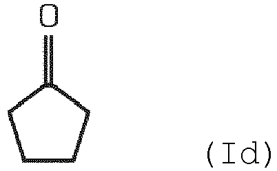
- the fluoroketone represents at least one compound selected from the group consisting of the compounds defined by the following structural formulas, in which at least one hydrogen atom is substituted by a fluorine atom:
- Fluoroketones especially fluoroketones a), with a branched alkyl chain are generally preferred because their boiling points are lower than the boiling points of the corresponding compounds (i.e. with the same empirical formula) with a linear alkyl chain.
- the fluoroketone a) is a perfluoroketone, specifically with the empirical formula C 5 F 10 O, ie completely saturated, that is to say without double or triple bonds between carbon atoms.
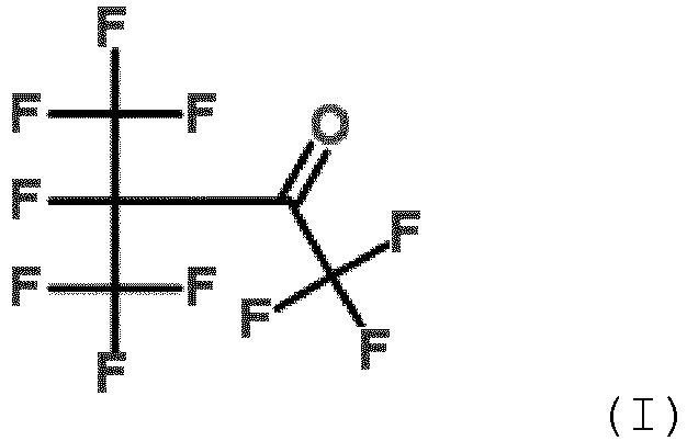
- the fluoroketone is more preferably selected from the group consisting of 1,1,1,3,4,4,4-heptafluoro-3- (trifluoromethyl) butan-2-one (also referred to as decafluoro-2-methylbutan-3-one) , 1,1,1,3,3,4,4,5,5,5-decafluoropentan-2-one, 1,1,1,2,2,4,4,5,5,5-decafluoropentan-3 -one and octafluorocylcopentanone, and is most preferably 1,1,1,3,4,4,4-heptafluoro-3- (trifluoromethyl) butan-2-one.
- 1,1,1,3,4,4,4-heptafluoro-3- (trifluoromethyl) butan-2-one can be represented by the following structural formula (I): 1,1,1,3,4,4,4-heptafluoro-3- (trifluoromethyl) butan-2-one, which is referred to here briefly as "C5-ketone” and the molecular formula CF 3 C (O) CF (CF 3 ) 2 or C 5 F 10 O is particularly preferred for use in high and medium voltage insulation applications because it has the advantages of high dielectric strength, in particular when mixed with a dielectric background or carrier gas, and a very low GWP value and a deep boiling point. It also has an ODP (Ozone Depletion Potential) value of 0 and is practically non-toxic.
- C5-ketone the molecular formula CF 3 C (O) CF (CF 3 ) 2 or C 5 F 10 O
- fluoroketone a a fluoroketone with exactly 5 carbon atoms according to the above explanations, which is referred to here briefly as fluoroketone a), and a fluoroketone with exactly 6 carbon atoms or exactly 7 carbon atoms, which is referred to here briefly as fluoroketone c), simultaneously in the dielectric Isolation medium are included.
- fluoroketone c a fluoroketone with exactly 6 carbon atoms or exactly 7 carbon atoms
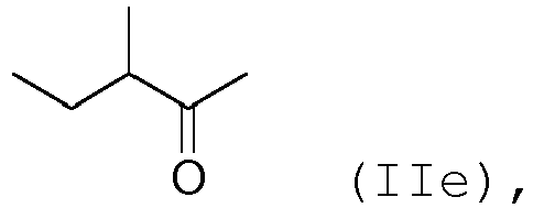
- the further fluoroketone c) constitutes at least one compound selected from the group consisting of the following structural formulas defined compounds in which at least one hydrogen atom is substituted by a fluorine atom: as well as all fluoroketones with exactly 6 carbon atoms, in which the at least partially fluorinated alkyl chain of the fluoroketone forms a ring which is substituted by one or more alkyl chains (IIh); and / or at least one compound selected from the group consisting of the compounds defined by the following structural formulas, in which at least one hydrogen atom is substituted by a fluorine atom: and called dodecafluorocycloheptanone, as well as all fluoroketones with exactly 7 carbon atoms, in which the at least partially fluorinated alkyl chain of the fluoroketone forms a ring which is substituted by one or more alkyl chains (IIIo).
- the present invention includes all compounds and any combination of compounds selected from the group consisting of the compounds of the structural formulas (Ia) to (Ii), (IIa) to (IIh), (IIIa) to (IIIo) and mixtures thereof.
- fluoroketone c like fluoroketone a), is a perfluoroketone and / or has a branched alkyl chain, in particular an at least partially fluorinated alkyl chain, and / or is a completely saturated compound.
- the fluoroketone c) has the empirical formula C 6 F 12 O, ie represents a completely saturated compound, that is to say a compound without double or triple bonds between carbon atoms.
- the fluoroketone c) is preferably selected from the group consisting of 1,1,1,2,4,4,5,5,5-nonafluoro-2- (trifluoromethyl) pentan-3-one (also as dodecafluoro-2-methylpentane -3-one), 1,1,1,3,3,4,5,5,5-nonafluoro-4- (trifluoromethyl) pentan-2-one (also called dodecafluoro-4-methylpentan-2-one) ), 1,1,1,3,4,4,5,5,5-nonafluoro-3- (trifluoromethyl) pentan-2-one (also called dodecafluoro-3-methylpentan-2-one), 1.1 , 1,4,4,4-Hexafluoro-3,3-bis (trifluoromethyl) butan-2-one (also called dodecafluoro-3,3- (dimethyl) butan-2-one), dodecafluorohexan-2-one , Dodecafluorohexan-2-
- 1,1,1,2,4,4,5,5,5-nonafluoro-2- (trifluoromethyl) pentan-3-one (also called dodecafluoro-2-methylpentan-3-one) can be represented by the following structural formula ( II) are shown:
- C6 ketone 1,1,1,2,4,4,5,5,5-nonafluoro-4- (trifluoromethyl) pentan-3-one (here briefly referred to as "C6 ketone" with the molecular formula C 2 F 5 C (O ) CF (CF 3 ) 2 ) is particularly preferred for high-voltage insulation applications because of its good insulating properties and its extremely low GWP value.
- a fluoronitrile in particular a perfluoronitrile, can also be used as the organofluorine compound.
- the fluoronitrile in particular the perfluoronitrile, preferably has four carbon atoms.
- the fluoronitrile can be a perfluoroalkyl nitrile, in particular perfluorobutyronitrile (C 3 F 7 CN).
- perfluoroisobutyronitrile (according to the formula (CF 3 ) 2 CFCN) and / or perfluoro-2-methoxypropanenitrile (according to the formula CF 3 CF (OCF 3 ) CN) can be used as the fluoronitrile.
- perfluoroisobutyronitrile is particularly preferred because of its low toxicity.
- the insulation medium contains a carrier gas comprising at least one component selected from the group consisting of air, an air component, in particular nitrogen (N 2 ) and / or oxygen (O 2 ), and carbon dioxide (CO 2 ), and mixtures thereof.
- the insulation medium particularly preferably contains carbon dioxide and optionally an air component, in particular oxygen and / or nitrogen.
- the insulation medium is a gas mixture containing carbon dioxide and oxygen.
- the ratio of the amount of carbon dioxide to the amount of oxygen is preferably in a range from 50:50 to 100: 1.
- the ratio of the amount of carbon dioxide to the amount of oxygen is in a range from 80:20 to 95: 5, more preferably from 85:15 to 92: 8, more preferably from 87:13 to less than 90:10, and in particular approx. Is 89:11.
- butyl rubber is used according to the invention as the sealing material for the gas seal.
- Butyl rubber is also known to the person skilled in the art under the designation IIR (isobutene-isoprene rubber or isobutene-isoprene rubber) and can be represented in particular by means of the following structural formula: where k, l, m are integer indices.
- IIR isobutene-isoprene rubber or isobutene-isoprene rubber
- butyl rubber includes both unmodified butyl rubber and modified butyl rubber, such as chlorobutyl rubber (CIIR) or bromobutyl rubber (BIIR).
- the butyl rubber has an isoprene content in the range from 1 mol% to 3 mol%, preferably from 1.5 mol% to 2.5 mol%, and particularly preferably from approx. 2 mol%.
- Corresponding butyl rubbers are distinguished by a particularly low permeability to the carrier gas, in particular to CO 2 and / or O 2 and / or N 2 .
- butyl rubber as used in connection with the present invention includes any kind of butyl rubbers, for example also those which are obtainable by vulcanization using a vulcanization system based on sulfur or a sulfur donor.
- the butyl rubber is particularly preferably obtained by vulcanization by means of a resin-based vulcanization system, since an increased carbon-carbon crosslinking can thereby be achieved.
- the resin can in particular be a phenolic resin, in particular a resin based on an alkylphenol-formaldehyde derivative.
- the gas seal is in the form of a closed ring with any cross section.
- gas seals Any method is conceivable for the production of the gas seals which the person skilled in the art deems suitable in the specific case.
- the gas seals can be injection molded getting produced.
- Further exemplary embodiments are endless O-rings or glued O-rings.
- the present invention includes embodiments in which all of the present gas seals contain or consist of butyl rubber as the sealing material, as well as embodiments in which this is only the case for a part of the present gas seals.
- this also includes parts with a butyl rubber coating, parts coated with butyl rubber and parts molded with butyl rubber.
- the gas seals in addition to the at least one gas seal which contains butyl rubber, there is at least one further gas seal made of a different material (e.g. EPDM), it may be preferred to mark the gas seals. This can be done by means of a visible color point or a special haptic property. The marking allows the gas seals to be replaced earlier to be easily recognized, especially when using additional sealing materials with properties that are optimized compared to the insulation medium (for example improved or reduced permeability). In other words, it can thus be avoided that the gas seals according to the present invention, which have improved properties (for example reduced permeability), are replaced at a point in time at which they are still fully functional.
- EPDM e.g. EPDM
- the invention relates to any device for generating, transmitting, distributing and / or using electrical energy, in the interior of which at least one insulation space is formed.
- the device or the component is this device a switchgear, in particular a gas-insulated metal-enclosed switchgear, a switch, in particular an earthing switch, a disconnector, a switch disconnector and / or a circuit breaker, a high-voltage circuit breaker optionally with a heating chamber to provide a self-blowing effect, a transformer, in particular a distribution transformer or a power transformer, an electrical rotating machine, a generator, a motor, a drive, a semiconducting component and / or a power electronics device, and / or a converter station.
- a switchgear in particular a gas-insulated metal-enclosed switchgear
- a switch in particular an earthing switch, a disconnector, a switch disconnector and / or a circuit breaker
- a high-voltage circuit breaker optionally with a heating chamber to provide a self-blowing effect
- a transformer in particular a distribution transformer or a power transformer, an electrical rotating machine, a generator, a
- the present invention also relates to a gas seal for the device or component.
- this gas seal contains butyl rubber as the sealing material.
- the term "gas seal” thus includes both gas seals which contain additional material in addition to butyl rubber, and gas seals which essentially consist of butyl rubber.
- the gas permeability rate compared to CO 2 for butyl rubber (IIR) is at least 25 times lower than for the other plastics EPDM (ethylene-propylene-diene rubber) tested as comparative examples.
- EPDM ethylene-propylene-diene rubber
- FKM fluororubber
- NBR nitrile-butadiene-rubber
- the permeability to N 2 as a carrier gas gas permeability rates which were significantly lower than those for EPDM were determined at 20 ° C. for butyl rubber.
- the butyl rubber which is inert to the organofluorine compound of the insulation medium thus shows only a very low permeability to the tested carrier gases of the insulation medium and in particular a far lower permeability than EPDM.
- the permeability of butyl rubber is also greatly reduced in comparison to nitrile rubber, which, depending on the organofluorine compound used, shows an insufficient material compatibility.
- the device 2 shown comprises an encapsulation 4 which surrounds an insulation space 6, in which a current-carrying or voltage-carrying component 8 is arranged and which contains a dielectric insulation medium 10 surrounding the current-carrying or voltage-carrying component.
- the insulation medium 10 contains on the one hand an organofluorine compound and on the other hand a carrier gas, in the specific case nitrogen (N 2 ).
- the current-carrying component 8 is held by an insulator 12, which is connected to the encapsulation 4 on its side facing away from the current-carrying component 8 via a metal ring 14 fastened by means of a clamping bolt 13.
- the insulator 12 has a circumferential bead 16 for attaching a sealing system.
- a gas seal 20 is provided between the encapsulation 4 and the insulator 12, which is intended to ensure that the insulation medium 10 is sealed by an between the encapsulation 4 and leakage from the insulator 12 or the metal ring 14 can escape, or that air from the environment 181 can penetrate into the insulation space 6.
- the gas seal 20 contains butyl rubber as the sealing material or the gas seal 20 consists of butyl rubber as the sealing material.
- the butyl rubber in the gas seal 20 has an isoprene content in the range from 1 mol% to 3 mol%, preferably from 1.5 mol% to 2.5 mol%, and particularly preferably from approximately 2 mol% on.
- only part of the gas seal (20) contains or consists of butyl rubber.
- the gas seal 20 can have a butyl rubber coating or be coated with butyl rubber or be extrusion-coated with butyl rubber.
- At least one gas seal 20 which contains butyl rubber
- at least one further gas seal (not shown) made of another material, in particular EPDM, is present.
- the gas seal 20 and / or the further gas seal can be marked.
- the marking can preferably be realized by a visible color point or by a special haptic property.
Landscapes
- Chemical & Material Sciences (AREA)
- Spectroscopy & Molecular Physics (AREA)
- Physics & Mathematics (AREA)
- Engineering & Computer Science (AREA)
- Power Engineering (AREA)
- Organic Chemistry (AREA)
- Oil, Petroleum & Natural Gas (AREA)
- Health & Medical Sciences (AREA)
- Medicinal Chemistry (AREA)
- Polymers & Plastics (AREA)
- Chemical Kinetics & Catalysis (AREA)
- Materials Engineering (AREA)
- Sealing Material Composition (AREA)
- Gas-Insulated Switchgears (AREA)
Description
- Die vorliegende Erfindung betrifft eine Vorrichtung zur Erzeugung, Übertragung, Verteilung und/oder Verwendung von elektrischer Energie oder eine Komponente davon, sowie eine Gasdichtung für eine solche Vorrichtung bzw. Komponente.
- In Vorrichtungen der eingangs genannten Art werden häufig flüssige oder gasförmige dielektrische Isolationsmedien für die dielektrische Isolation der stromführenden Komponente eingesetzt. Unter anderem finden solche Isolationsmedien in gasisolierten Schaltanlage (GIS), gasisolierten Rohrleitern (GIL) oder Transformatoren standardmässig Anwendung. So wird beispielsweise in metallgekapselten GIS die stromführende Komponente in einem Gehäuse angeordnet, welches einen Isolationsraum begrenzt, in dem ein Isolationsgas enthalten ist, um das Gehäuse von der stromführenden Komponenten zu isolieren und derart einen elektrischen Durchschlag zu verhindern.
- Zur Stromunterbrechung in Hochspannungsschaltanlagen übernimmt das Isolationsgas zudem die Funktion eines Lichtbogenlöschgases.
-
US 8 492 672 offenbart einen Ableiter zur Lichtbogenlöschung mittels einer beweglichen Elektrode. Im Bereitsschaftszustand ist ein Isolationsraum zwischen feststehender und beweglicher Elektrode mit einer Isolationsflüssigkeit oder mit einem Isolationsgas aus SF6, Druckluft, N2, Perfluor- oder Fluor-Chlor-Karbonverbindungen gefüllt und gegebenenfalls mit einer grossflächigen, membranartigen Feststoffisolation z.B. aus Butylkautschuk isoliert. Die membranartige Feststoffisolation is so ausgelegt, dass sie bei Aktivierung des Ableiters von der beweglichen Elektrode durchschlagen werden kann. -
EP 2 284 854 offenbart eine gasisolierte Schaltanlage, die mit Lichtbogenlöschgas aus SF6, Luft, N2, CO2, O2, H2, oder Perfluoro- oder Hydrofluor-Karbonverbindungen betrieben wird. Probleme mit der Gasdichtigkeit bei Verwendung von H2 oder CO2 werden dadurch gelöst, dass ein grösseres Bauvolumen mit mehr Gasvorrat bei etwas längerer Gasdichtung oder doppelt dicke Gasdichtungen gewählt werden oder dass H2 durch das weniger diffusionsfreudige CH4 ersetzt wird. Als Dichtungsmaterialien werden Nitrilkautschuk, Fluorkautschuk, Silikonkautschuk, Akrylkautschuk, Äthylen-Propylen-Kautschuk, Äthylen-Propylen-Diene-Kautschuk (EPDM), Butylkautschuk, Urethankautschuk, Hypalon oder Äthylenvinylacetat-Harz vorgeschlagen. -
WO 2008/073790 offenbart Isolationsgase für gasisolierte Schaltanlagen mit Siedepunkten tiefer als -20°C, darunter diverse Fluoräther, ein Fluormonoketone mit 3 Kohlenstoffatomen, ein Fluordiketon mit 4 Kohlenstoffatomen, diverse Fluorolefine, und spezielle Fluornitrile mit 1 oder 2 oder 3 Kohlenstoffatomen. - Als Isolationsgas bzw. Lichtbogenlöschgas wird häufig Schwefelhexafluorid (SF6) verwendet, welches nicht nur äusserst gute dielektrische Eigenschaften aufweist, sondern im Übrigen auch chemisch praktisch inert und nicht entflammbar ist.
- Allerdings sind in jüngerer Vergangenheit Organofluorverbindungen als interessante Alternativen zu SF6 vorgeschlagen worden. Diese Organofluorverbindungen weisen ein äusserst geringes Treibhauspotential (Global Warming Potential; GWP) auf und ein Ozonabbaupotential (Ozone Depletion Potential; ODP) von 0.
- So wird etwa in
WO 2010/142346 ein dielektrisches Isolationsmedium offenbart, welches ein 4 bis 12 Kohlenstoffatome aufweisendes Fluorketon enthält. Weiter wird inWO 2012/080246 ein exakt 5 Kohlenstoffatome aufweisendes Fluorketon (im Folgenden: "C5K") offenbart, welches in einer Mischung mit einer sich von dem C5K unterscheidenden Isolationsgaskomponente vorliegt. - Es hat sich gezeigt, dass Fluorketone aussergewöhnlich gute Isolationseigenschaften aufweisen. Insbesondere verfügen sie über eine hohe dielektrische Festigkeit und sind zudem für die Löschung von Lichtbögen geeignet. Gleichzeitig weisen sie eine sehr niedrige Toxizität auf. Weiter haben sich Mischungen als besonders vorteilhaft erwiesen, in denen das Fluorketon zusammen mit O2, N2 und/oder CO2 als Trägergas (oder "Hintergrundgas") vorliegt. Allerdings weisen die als SF6-Alternative in Frage kommenden Fluorketone einen relativ hohen Siedepunkt auf. Der Partialdruck der Fluorketone ist bei Betriebsbedingungen der Vorrichtung somit relativ gering.
- Um eine ausreichend gute dielektrische Isolation zu erhalten, wird daher eine relativ hohe Gasdichte der Fluorketonenthaltenden Gasmischungen gewählt. Dies wiederum bedingt, dass das Gehäuse, welches den Isolationsraum begrenzt, einem relativ hohen Druck standhalten können muss, bzw. dass auch bei relativ hohem Druck im Isolationsraum ein Entweichen des Isolationsgases wirksam verhindert werden kann.
- Um ein Entweichen des Isolationsgases zu verhindern, werden üblicherweise Gasdichtungen wie z.B. Dichtringe eingesetzt.
- Mit diesen soll insbesondere an Grenzflächen eine Abdichtung des Isolationsraums von einem anderen Raum, insbesondere von der Umgebung der Vorrichtung, erzielt werden. Würde eine solche Abdichtung nicht gewährleistet werden können, müssten die Intervalle für die Wartung der Vorrichtung, und insbesondere für das Wiederherstellen der gewünschten Isolationsgaszusammensetzung, verkürzt werden, d.h. dass die Vorrichtung frühzeitig abgestellt werden müsste, um wenigstens einen Teil des Isolationsgases zu ersetzen, was offensichtlich nachteilig ist.
- Als Material für eine Gasdichtung kommt prinzipiell etwa EPDM in Frage, welches im Zusammenhang mit SF6 in Hochspannungsanlagen als Dichtungsmaterial der Wahl beschrieben wird. Allerdings wurde festgestellt, dass Elastomere in der Regel eine relativ hohe Gaspermeabilität aufweisen. Insbesondere weisen EPDM-Dichtungen trotz den ansonsten hervorragenden Eigenschaften bei dem erwähnten hohen Druck eine relativ hohe Permeabilität gegenüber einzelnen Trägergaskomponenten, insbesondere O2, CO2 und N2, auf.
- Zudem hat sich gezeigt, dass Organofluorverbindungen trotz ihrer Reaktionsträgheit bis zu einem gewissen Grad mit einzelnen festen Komponenten der Vorrichtung reagieren und dabei abgebaut werden können, womit einerseits die Funktionalität des Isolationsgases direkt tangiert wird. Andererseits kann auch die genannte feste Komponente durch die Interaktion mit der Organofluorverbindung Schaden nehmen, was insbesondere dann von Relevanz ist, wenn es sich bei der festen Komponente um eine Gasdichtung handelt und diese im schadhaften Zustand eine erhöhte Leckagerate aufweist. Somit kann aufgrund der erwähnten Materialinkompatibilität die Funktionalität des Isolationsgases auch indirekt, nämlich durch ein verstärktes Ausströmen des Trägergases durch die schadhafte Gasdichtung, beeinträchtigt werden.
- Aufgabe der vorliegenden Erfindung ist es somit, eine ein alternatives Isolationsmedium verwendende Vorrichtung der eingangs genannten Art zur Verfügung zu stellen, in welcher das Isolationsmedium über eine lange Periode voll funktionsfähig ist und welche somit nur relativ selten gewartet werden muss.
- Insbesondere soll auch bei einem hohen Druck im Isolationsraum der Vorrichtung eine möglichst vollständige Gasabdichtung des Isolationsraums gewährleistet werden.
- Im Spezifischen sollen die in der Vorrichtung vorliegenden Gasdichtungen eine hohe Materialkompatibilität mit der Organofluorverbindung aufweisen und gleichzeitig eine tiefe Permeabilität gegenüber dem in Mischung mit der Organofluorverbindung vorliegenden Trägergas zeigen, insbesondere gegenüber O2, CO2 und/oder N2. Im Übrigen soll die Gasdichtung auch eine tiefe Permeabilität gegenüber Wasser haben, um zu vermeiden, dass dieses in den Isolationsraum eindringen und dort die Zersetzung des Isolationsgases oder einzelner Komponenten davon beschleunigen kann.
- Die erfindungsgemässe Aufgabe wird gelöst durch den Gegenstand des Anspruchs 1. Bevorzugte Ausführungsformen sind in den abhängigen Ansprüchen wiedergegeben.
- Gemäss Anspruch 1 wird im Innern der Vorrichtung zur Erzeugung, Übertragung, Verteilung und/oder Verwendung von elektrischer Energie mindestens ein Isolationsraum ausgebildet, in welchem eine elektrisch leitende Komponente angeordnet ist und welcher ein die elektrische leitende Komponente umgebendes dielektrisches Isolationsmedium enthält. Dabei enthält das Isolationsmedium
- a) mindestens eine Organofluorverbindung ausgewählt aus der Gruppe bestehend aus Fluorketonen, Fluornitrilen sowie Mischungen davon und
- b) ein Trägergas umfassend mindestens eine Komponente ausgewählt aus der Gruppe bestehend aus Luft, einer Luftkomponente, CO2, oder einer Mischung dieser Komponenten.
- Dieses Isolationsmedium weist eine hohe dielektrische Festigkeit auf. Das Isolationsmedium ist aufgrund seiner ausgezeichneten Lichtbogenlöschungseigenschaften im Speziellen auch für Schaltanlagen geeignet.
- Gleichzeitig weist das Isolationsmedium ein äusserst geringes Treibhauspotential, ein Ozonabbaupotential von 0 und eine sehr niedrige Toxizität auf.
- Zur Abdichtung des mindestens einen Isolationsraums von einem weiteren Raum umfasst die Vorrichtung erfindungsgemäss mindestens eine Gasdichtung, welche als Dichtungsmaterial Butyl-Kautschuk enthält. Im Begriff "Gasdichtung" sind damit sowohl Gasdichtungen mitumfasst, die nebst Butyl-Kautschuk weiteres Material enthalten, als auch Gasdichtungen die im Wesentlichen bzw. vollständig aus Butyl-Kautschuk bestehen.
- Der "weitere Raum" im Sinne der vorliegenden Erfindung stellt in der Regel die Umgebung der Vorrichtung dar. Es ist aber denkbar, dass der weitere Raum sich auf einen Raum bzw. ein Kompartiment der Vorrichtung bezieht, gegenüber welchem der Isolationsraum mindestens annähernd hermetisch abzudichten ist.
- In der Regel unterscheidet sich das im weiteren Raum enthaltene Medium vom Isolationsmedium im Isolationsraum. Im Falle, dass der weitere Raum die Umgebung der Vorrichtung darstellt, handelt es sich bei diesem Medium um Luft. Denkbar ist aber auch, dass das Medium seinerseits ein weiteres Isolationsmedium darstellt, insbesondere ein Isolationsmedium mit gegenüber Luft erhöhten dielektrischen Eigenschaften.
- Es hat sich gezeigt, dass durch die erfindungsgemässe Auswahl von Butyl-Kautschuk als Dichtungsmaterial Gasdichtungen erhalten werden, die eine sehr hohe Materialkompatibilität gegenüber Organofluorverbindung aufweisen. Eine hohe Materialkompatibilität zwischen Isolationsmedium und Dichtungsmaterial ist insbesondere bei der Verwendung von 1,1,1,3,4,4,4-Heptafluoro-3-(trifluoromethyl)butan-2-on, welches hier kurz als "C5-Keton" bezeichnet wird, gegeben. C5-Keton wird, wie weiter unten ausgeführt, aufgrund seiner sich in Kombination mit einem Trägergas ergebenden dielektrischen Eigenschaften sowie seiner hohen Umweltverträglichkeit besonders bevorzugt als Organofluorverbindung verwendet. Ebenso weist die Butyl-Kautschuk Gasdichtung eine hohe Materialkompatibilität zu Isolationsgasen auf, die Fluornitril enthalten, insbesondere die Perfluorobutyronitril (C3F7CN) und bevorzugt Perfluoroisobutyronitril gemäss der Formel (CF3)2CFCN und/oder Perfluoro-2-methoxypropannitril gemäss der Formel CF3CF(OCF3)CN enthalten.
- Die hohe Materialkompatibilität hat nicht nur den Vorteil, dass der reaktive Abbau von Organofluorverbindungen vermindert oder eliminiert werden kann. Auch die Gasdichtung weist durch die verbesserte Materialkompatibilität eine erhöhte Langzeitstabilität auf, d.h. dass selbst dann, wenn sie über eine längere Periode Organofluorverbindungen ausgesetzt sind, die Funktion nicht beeinträchtigt ist bzw. erhalten bleibt.
- Im Übrigen kann durch die erfindungsgemässe Auswahl von Butyl-Kautschuk gewährleistet werden, dass die Permeabilität gegenüber dem Trägergas oder einer Trägergaskomponenten, also insbesondere gegenüber CO2, O2, N2 und/oder Luft, sehr gering ist. Insbesondere ist die Permeabilität wesentlich tiefer als etwa bei der Verwendung von EPDM als Dichtungsmaterial.
- Letztendlich kann erfindungsgemäss somit eine gattungsgemässe Vorrichtung mit einem Isolationsmedium auf Basis einer Organofluorverbindung erhalten werden, in welcher eine gute Gasabdichtung des das Isolationsmedium enthaltenden Raums auch bei relativ hohem Druck gewährleistet wird. Da das für die Gasabdichtung verwendete Dichtungsmaterial nicht nur eine geringe Permeabilität gegenüber dem im Isolationsmedium enthaltenen Trägergas oder einzelnen Trägergaskomponenten, sondern gleichzeitig auch eine gute Materialkompatibilität mit der Organofluorverbindung aufweist, ist ein Ersetzen des Isolationsmediums und/oder der Gasdichtung nur relativ selten erforderlich, was insgesamt zu einem wartungsarmen Betrieb der Vorrichtung beiträgt. Was die geringe Permeabilität gegenüber Wasser betrifft, so kann dadurch vermieden werden, dass Wasser in den Isolationsraum eindringen und sich an einer potentiellen Zersetzung des Isolationsgases oder Komponenten davon, insbesondere der Organofluorverbindung, beteiligen kann.
- Konkret hat sich gezeigt, dass die Intervalle für das Wiederbefüllen der Vorrichtung mit Isolationsmedium erfindungsgemäss um einen Faktor von ca. 3 verlängert werden können. Da das erfindungsgemäss verwendete Dichtungsmaterial Butyl-Kautschuk gut verfügbar und relativ kostengünstig ist, fallen hierfür keine materialbedingten Mehrkosten an.
- Wie erwähnt ist im Isolationsraum ein dielektrisches Isolationsmedium enthalten, welches mindestens eine Organofluorverbindung ausgewählt aus der Gruppe bestehend aus Fluorketonen, insbesondere Perfluorketonen, Fluornitrilen, insbesondere Perfluornitrilen, sowie Mischungen davon umfasst.
- Die Erfindung umfasst Ausführungsformen, in welchen das Isolationsmedium entweder eine einzige Verbindung aus der Gruppe bestehend aus Fluorketonen, insbesondere Perfluorketonen, Fluornitrilen, insbesondere Perfluornitrilen, oder aber eine Mischung aus mindestens zwei Verbindungen dieser Gruppe enthält.
- Das Isolationsmedium kann ein Fluorketon sein, insbesondere ein Fluorketon mit 4 bis 12 Kohlenstoffatomen.
- Der Begriff "Fluorketon", wie er im Zusammenhang dieser Erfindung verwendet wird, ist breit auszulegen und umfasst insbesondere sowohl Perfluorketone als auch Hydrofluorketone und umfasst weiter gesättigte Verbindungen und ungesättigte Verbindungen, d.h. Verbindungen mit Doppel- und/oder Dreifachbindungen zwischen Kohlenstoffatomen. Die wenigstens teilweise fluorierten Alkylketten der Fluorketone können linear oder verzweigt sein oder können einen Ring bilden, welcher wahlweise mit einer oder mehreren Alkylgruppen substituiert ist. In beispielhaften Ausführungsformen ist das Fluorketon ein Perfluorketon, wobei in diesem eine verzweigte Alkylkette vorliegen kann, welche insbesondere eine wenigstens teilweise fluorierte Alkylkette sein kann und welche vorzugsweise vollständig fluoriert ist.
- Gemäss einer besonders bevorzugten Ausführungsform weist das Fluorketon 5 oder 6 Kohlenstoffatome auf. Solche Fluorketone sind bis zu 500°C thermisch stabil.
- Fluorketone mit genau 5 Kohlenstoffatomen werden hier kurz als Fluorketone a) bezeichnet.
- Im Besonderen stellt das Fluorketon wenigstens eine Verbindung ausgewählt aus der Gruppe bestehend aus den durch die folgenden Strukturformeln definierten Verbindungen dar, in welchen wenigstens ein Wasserstoffatom durch ein Fluoratom substituiert ist:




- Fluorketone, insbesondere Fluorketone a), mit einer verzweigten Alkylkette sind in der Regel bevorzugt, weil ihre Siedepunkte tiefer sind als die Siedepunkte der entsprechenden Verbindungen (d.h. mit derselben Summenformel) mit einer linearen Alkylkette.
- Gemäss einer besonderen Ausführungsform ist das Fluorketon a) ein Perfluorketon, spezifisch mit der Summenformel C5F10O, d.h. vollständig gesättigt, also ohne Doppel- oder Dreifachbindungen zwischen Kohlenstoffatomen. Bevorzugter ist das Fluorketon ausgewählt aus der Gruppe bestehend aus 1,1,1,3,4,4,4-Heptafluoro-3-(trifluoromethyl)butan-2-on (auch als Decafluor-2-methylbutan-3-on bezeichnet), 1,1,1,3,3,4,4,5,5,5-Decafluoropentan-2-on, 1,1,1,2,2,4,4,5,5,5-Decafluoropentan-3-on und Octafluorocylcopentanon, und ist am meisten bevorzugt 1,1,1,3,4,4,4-Heptafluoro-3-(trifluoromethyl)butan-2-on.
- 1,1,1,3,4,4,4-Heptafluoro-3-(trifluoromethyl)butan-2-on kann durch die folgende Strukturformel (I) dargestellt werden:
- Denkbar ist zudem, dass ein Fluorketon mit genau 5 Kohlenstoffatomen gemäss obigen Ausführungen, welches hier kurz als Fluorketon a) bezeichnet wird, und ein Fluorketon mit genau 6 Kohlenstoffatomen oder genau 7 Kohlenstoffatomen, welches hier kurz als Fluorketon c) bezeichnet wird, gleichzeitig im dielektrischen Isolationsmedium enthalten sind. Somit resultiert ein Isolationsmedium mit mehr als einem Fluorketon, wobei jedes Fluorketon für sich zur dielektrischen Festigkeit des Isolationsmediums beiträgt.
- Gemäss einer besonderen Ausführungsform stellt das weitere Fluorketon c) wenigstens eine Verbindung ausgewählt aus der Gruppe bestehend aus den durch die folgenden Strukturformeln definierten Verbindungen dar, in welchen wenigstens ein Wasserstoffatom durch ein Fluoratom substituiert ist:




und/oder wenigstens eine Verbindung ausgewählt aus der Gruppe bestehend aus den durch die folgenden Strukturformeln definierten Verbindungen, in welchen wenigstens ein Wasserstoffatom durch ein Fluoratom substituiert ist:


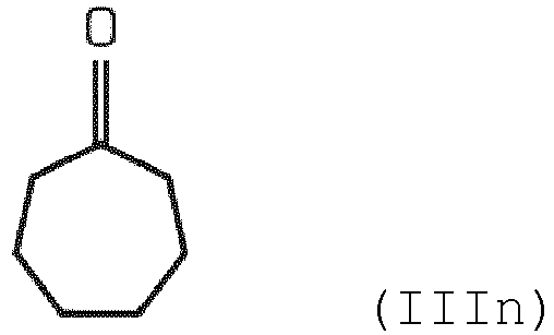
sowie allen Fluorketonen mit genau 7 Kohlenstoffatomen, in welchem die wenigstens teilweise fluorierte Alkylkette des Fluorketons einen Ring bildet, welcher mit einer oder mehreren Alkylketten substituiert ist (IIIo). - Die vorliegende Erfindung umfasst alle Verbindungen sowie jede Kombination von Verbindungen ausgewählt aus der Gruppe bestehend aus den Verbindungen der Strukturformeln (Ia) bis (Ii), (IIa) bis (IIh), (IIIa) bis (IIIo) und Mischungen davon.
- Gemäss einer besonderen Ausführungsform ist Fluorketon c), wie Fluorketon a), ein Perfluorketon und/oder hat eine verzweigte Alkylkette, insbesondere eine wenigstens teilweise fluorierte Alkylkette, und/oder ist eine vollständig gesättigte Verbindung.
- Insbesondere weist das Fluorketon c) die Summenformel C6F12O auf, d.h. stellt eine vollständig gesättigte Verbindung dar, also eine Verbindung ohne Doppel- oder Dreifachbindungen zwischen Kohlenstoffatomen.
- Bevorzugt ist das Fluorketon c) ausgewählt aus der Gruppe bestehend aus 1,1,1,2,4,4,5,5,5-Nonafluoro-2-(trifluoromethyl)pentan-3-on (auch als Dodecafluoro-2-methylpentan-3-on bezeichnet), 1,1,1,3,3,4,5,5,5-Nonafluoro-4-(trifluoromethyl)pentan-2-on (auch als Dodecafluoro-4-methylpentan-2-on bezeichnet), 1,1,1,3,4,4,5,5,5-Nonafluoro-3-(trifluoromethyl)pentan-2-on (auch als Dodecafluoro-3-methylpentan-2-on bezeichnet), 1,1,1,4,4,4-Hexafluoro-3,3-bis-(trifluoromethyl)butan-2-on (auch als Dodecafluoro-3,3-(dimethyl)butan-2-on bezeichnet), Dodecafluorohexan-2-on, Dodecafluorohexan-3-on und Decafluorocyclohexanon, und stellt insbesondere das erwähnte 1,1,1,2,4,4,5,5,5-Nonafluoro-2-(trifluoromethyl)pentan-3-on.
- 1,1,1,2,4,4,5,5,5-Nonafluoro-2-(trifluoromethyl)pentan-3-on (auch als Dodecafluoro-2-methylpentan-3-on bezeichnet) kann durch die folgende Strukturformel (II) dargestellt werden:

- 1,1,1,2,4,4,5,5,5-Nonafluoro-4-(trifluoromethyl)pentan-3-on (hier kurz als "C6-Keton" bezeichnet mit der Molekülformel C2F5C(O)CF(CF3)2) ist besonders für Hochspannungsisolationsanwendungen besonders bevorzugt wegen seiner guten isolierenden Eigenschaften und seinem extrem tiefen GWP-Wert.
- Wie ebenfalls oben erwähnt, kann als Organofluorverbindung auch ein Fluoronitril verwendet werden, insbesondere ein Perfluoronitril.
- Bevorzugt weist das Fluornitril, insbesondere das Perfluoronitril, vier Kohlenstoffatome auf.
- Gemäss einer weiter bevorzugten Ausführungsform kann das Fluoronitril ein Perfluoroalkylnitril sein, insbesondere Perfluorobutyronitril (C3F7CN).
- Insbesondere kann als Fluornitril Perfluoroisobutyronitril (gemäss der Formel (CF3)2CFCN) und/oder Perfluoro-2-methoxypropannitril (gemäss der Formel CF3CF(OCF3)CN) sein. Von diesen ist Perfluoroisobutyronitril aufgrund seiner geringen Toxizität besonders bevorzugt.
- In generellen Ausführungsbeispielen sind solche Fluorketone und/oder Fluornitrile bevorzugt, die Siedepunkte bei Atmosphärendruck von höher (d.h. wärmer) als -5°C haben, und/oder die GWPs über 100 Jahre von weniger als 2500 haben, und/oder eine niedrige Toxizität haben.
- Wie erwähnt enthält das Isolationsmedium ein Trägergas umfassend mindestens eine Komponente ausgewählt aus der Gruppe bestehend aus Luft, einer Luftkomponente, insbesondere Stickstoff (N2) und/oder Sauerstoff (O2), sowie Kohlendioxid (CO2), und Mischungen davon. Besonders bevorzugt enthält das Isolationsmedium Kohlendioxid und wahlweise eine Luftkomponente, insbesondere Sauerstoff und/oder Stickstoff.
- Gemäss einer besonderen Ausführungsform ist das Isolationsmedium eine Gasmischung enthaltend Kohlendioxid und Sauerstoff. Dabei liegt das Verhältnis der Menge an Kohlendioxid zur Menge an Sauerstoff vorzugsweise in einem Bereich von 50:50 bis 100:1.
- Insbesondere im Hinblick auf eine Stromunterbrechung in einer Hochspannungsschaltanlage ist es besonders bevorzugt, dass das Verhältnis der Menge an Kohlendioxid zur Menge an Sauerstoff in einem Bereich von 80:20 bis 95:5 liegt, bevorzugter von 85:15 bis 92:8, noch bevorzugter von 87:13 bis weniger als 90:10, und insbesondere ca. 89:11 beträgt.
- Wie erwähnt wird als Dichtungsmaterial für die Gasdichtung erfindungsgemäss Butyl-Kautschuk verwendet. Butyl-Kautschuk ist dem Fachmann auch unter der Bezeichnung IIR (Isobuten-Isopren-Kautschuk bzw. Isobuten-Isopren-Rubber) bekannt und kann insbesondere mittels folgender Strukturformel dargestellt werden:

- Gemäss einer bevorzugten Ausführungsform weist der Butyl-Kautschuk im Hinblick auf eine gute Vulkanisierbarkeit einen Isopren-Anteil im Bereich von 1 mol-% bis 3 mol-%, vorzugsweise von 1.5 mol-% bis 2.5 mol-%, und besonders bevorzugt von ca. 2 mol-% auf. Entsprechende Butyl-Kautschuke zeichnen sich durch eine besonders tiefe Permeabilität gegenüber dem Trägergas, insbesondere gegenüber CO2 und/oder O2 und/oder N2, aus.
- Der Begriff "Butyl-Kautschuk", wie er im Zusammenhang mit der vorliegenden Erfindung verwendet wird, umfasst jegliche Art von Butyl-Kautschuken, z.B. auch solche, die über Vulkanisierung mittels eines auf Schwefel oder einem Schwefeldonor basierenden Vulkanisierungssystems erhältlich sind. Besonders bevorzugt wird der Butyl-Kautschuk über Vulkanisierung mittels eines auf einem Harz basierenden Vulkanisierungssystem erhalten, da dadurch eine erhöhte Kohlenstoff-Kohlenstoff-Vernetzung erreicht werden kann. Beim Harz kann es sich dabei insbesondere um ein phenolisches Harz handeln, im Speziellen um ein Harz auf Basis eines Alkylphenol-Formaldehyd-Derivats.
- Was die Dimension und die Form der Grösse der Gasdichtung betrifft, so sind alle diejenigen denkbar, die für die technische Anwendung, insbesondere die erforderlichen Dichtungs-Grössen, Dichtungs-Dicken und Dichtungs-Gasdichtigkeiten, geeignet sind.
- Gemäss einer besonders bevorzugten Ausführung liegt die Gasdichtung in Form eines geschlossenen Rings mit beliebigem Querschnitt vor. Denkbar sind etwa O-Ringe, in einer Form, in der sie typischerweise für eine Innenraum-GIS oder Freiluft-GIS Verwendung finden (GIS = Gasisolierte Schaltanlage).
- Nebst dem kreisförmigen Querschnitt, wie er bei den üblicherweise verwendeten O-Ringen vorliegt, sind auch andere Querschnitte denkbar, wie etwa ein X-förmiger oder ein rechteckförmiger Querschnitt. Weitere Ausführungsbeispiele sind nebst den erwähnten Gasdichtungen in konventioneller O-Ring-Form etwa auch Gasdichtungen in Form eines Doppel-O-Rings.
- Für die Herstellung der Gasdichtungen sind jegliche Verfahren denkbar, die der Fachmann im konkreten Fall für geeignet erachtet. Insbesondere können die Gasdichtungen im Spritzgussverfahren hergestellt werden. Weitere Ausführungsbeispiele sind Endlos-O-Ringe oder geklebte O-Ringe.
- Die vorliegende Erfindung umfasst Ausführungsformen, in der alle vorliegenden Gasdichtungen Butyl-Kautschuk als Dichtungsmaterial enthalten oder daraus bestehen, sowie Ausführungsformen, in denen dies nur für einen Teil der vorliegenden Gasdichtungen der Fall ist. Insbesondere mitumfasst sind somit auch Teile mit einer Butyl-Kautschuk-Beschichtung, mit Butyl-Kautschuk ummantelte und mit Butyl-Kautschuk umspritzte Teile.
- Im Fall, dass nebst der mindestens einen Gasdichtung, welche Butyl-Kautschuk enthält, mindestens eine weitere Gasdichtung aus einem anderen Material (z.B. EPDM) vorhanden ist, kann es bevorzugt sein, die Gasdichtungen zu markieren. Dies kann etwa mittels eines sichtbaren Farbpunktes oder einer speziellen haptischen Eigenschaft geschehen. Die Markierung erlaubt es, gerade bei Verwendung von zusätzlichen Dichtungsmaterialien mit gegenüber dem Isolationsmedium optimierten Eigenschaften (beispielsweise verbesserte bzw. verringerter Permeabilität), die früher zu ersetzenden Gasdichtungen einfach zu erkennen. Mit anderen Worten kann somit vermieden werden, dass die Gasdichtungen gemäss der vorliegenden Erfindung, welche verbesserte Eigenschaften (zum Beispiel verringerte Permeabilität) aufweisen, zu einem Zeitpunkt ersetzt werden, zu dem diese noch voll funktionsfähig sind.
- Prinzipiell bezieht sich die Erfindung auf jegliche Vorrichtung zur Erzeugung, Übertragung, Verteilung und/oder Verwendung von elektrischer Energie, in deren Innern mindestens ein Isolationsraum ausgebildet wird.
- Gemäss einer bevorzugten Ausführungsform ist die Vorrichtung bzw. die Komponente dieser Vorrichtung
eine Schaltanlage, insbesondere eine gasisolierte metallgekapselte Schaltanlage,
ein Schalter, insbesondere ein Erdungsschalter, ein Trennschalter, ein Lasttrennschalter und/oder ein Leistungsschalter,
ein Hochspannungsleistungsschalter optional mit einer Heizkammer zum Bereitstellen eines Selbstblaseffekts,
ein Transformator, insbesondere ein Verteiltransformator oder ein Leistungstransformator,
eine elektrische drehende Maschine, ein Generator, ein Motor, ein Antrieb, ein halbleitendes Bauelement und/oder eine Leistungselektronikeinrichtung, und/oder
eine Konverterstation. - Nebst der oben genannten Vorrichtung bzw. Komponente betrifft die vorliegende Erfindung zudem eine Gasdichtung für die Vorrichtung bzw. Komponente. Diese Gasdichtung enthält wie erwähnt Butyl-Kautschuk als Dichtungsmaterial. Im Begriff "Gasdichtung" sind damit sowohl Gasdichtungen mitumfasst, die nebst Butyl-Kautschuk weiteres Material enthalten, als auch Gasdichtungen, die im Wesentlichen aus Butyl-Kautschuk bestehen.
- Die Erfindung bzw. die damit erhaltene technische Wirkung wird anhand der nachfolgenden experimentellen Daten weiter veranschaulicht:
Gemäss einer ersten Versuchsanordnung wurde die Permeabilität von Butyl-Kautschuk gegenüber verschiedenen Trägergasen (CO2 bzw. N2) bei 20°C bestimmt. Die Resultate sind in Tabelle 1 wiedergegeben.Tabelle 1. Gaspermeabilitätsrate (cm3/m2*d*bar) Material EPDM (Vergleichs-beispiel) FKM (Vergleichsbeispiel) NBR (Vergleichsbeispiel) IIR (erfindungsgemäss) CO2; 20°C 1473 1470 1792 58.3 N2; 20°C 223 n.n. n.n. 2.85 - Wie aus den Resultaten ersichtlich ist, liegt bei 20°C die Gaspermeabilitätsrate gegenüber CO2 für Butyl-Kautschuk (IIR) um einen Faktor von mindestens 25 tiefer liegt als für die übrigen, als Vergleichsbeispiele getesteten Kunststoffe EPDM (Äthylen-Propylen-Dien Kautschuk), FKM (Fluorkautschuk), und NBR (Nitril-Butadiene-Kautschuk).
- Auch hinsichtlich der Permeabilität gegenüber N2 als Trägergas wurden bei 20°C für Butyl-Kautschuk wesentlich tiefere Gaspermeabilitätsraten bestimmt als für EPDM. Der gegenüber der Organofluorverbindung des Isolationsmediums inerte Butyl-Kautschuk zeigt somit gegenüber den getesteten Trägergasen des Isolationsmediums eine nur sehr geringe Permeabilität und insbesondere eine bei weitem geringere Permeabilität als EPDM. Insbesondere ist die Permeabilität von Butyl-Kautschuk auch im Vergleich zu Nitrilkautschuk, welcher je nach verwendeter Organofluorverbindung eine nicht ausreichende Materialverträglichkeit zeigt, stark vermindert.
- Die Erfindung wird weiter anhand der vorliegenden Figur veranschaulicht. Es zeigt:
- Fig. 1
- rein schematisch und in Schnittdarstellung einen Teil einer erfindungsgemässen Vorrichtung mit einer Gasdichtung zur Abdichtung eines Isolationsraums der Vorrichtung von der Umgebung der Vorrichtung.
- Die in
Fig. 1 gezeigte Vorrichtung 2 umfasst eine Kapselung 4, die einen Isolationsraum 6 umgibt, in welchem eine stromführende bzw. spannungsführende Komponente 8 angeordnet ist und welcher ein die stromführende bzw. spannungsführende Komponente umgebendes dielektrisches Isolationsmedium 10 enthält. Das Isolationsmedium 10 enthält zum einen eine Organofluorverbindung und zum anderen ein Trägergas, im konkreten Fall Stickstoff (N2). - Die stromführende Komponente 8 wird über einen Isolator 12 gehalten, welcher an seinem der stromführenden Komponente 8 abgewandten Seite über einen mittels eines Spannbolzens 13 befestigten Metallring 14 mit der Kapselung 4 verbunden ist. In der konkret gezeigten Ausführungsform weist der Isolator 12 einen umlaufenden Wulst 16 zur Anbringung eines Dichtungssystems auf.
- Zur Abdichtung des Isolationsraums 6 von der Umgebung 181 der Vorrichtung, welche den erfindungsgemässen "weiteren Raum" 18 definiert, ist zwischen der Kapselung 4 und dem Isolator 12 eine Gasdichtung 20 vorgesehen, welche gewährleisten soll, dass das Isolationsmedium 10 durch eine zwischen der Kapselung 4 und dem Isolator 12 bzw. dem Metallring 14 vorliegende Undichtigkeit entweichen kann, bzw. dass Luft aus der Umgebung 181 in den Isolationsraum 6 eindringen kann.
- Erfindungsgemäss enthält die Gasdichtung 20 Butyl-Kautschuk als Dichtungsmaterial oder besteht die Gasdichtung 20 aus Butyl-Kautschuk als Dichtungsmaterial.
- In Ausführungsbeispielen weist der Butyl-Kautschuk in der Gasdichtung 20 einen Isopren-Anteil im Bereich von 1 mol-% bis 3 mol-%, vorzugsweise von 1.5 mol-% bis 2.5 mol-%, und besonders bevorzugt von ca. 2 mol-% auf.
- In weiteren Ausführungsbeispielen enthält nur ein Teil der Gasdichtung (20) Butyl-Kautschuk oder besteht daraus. Insbesondere kann die Gasdichtung 20 eine Butyl-Kautschuk-Beschichtung aufweisen oder mit Butyl-Kautschuk ummantelt sein oder mit Butyl-Kautschuk umspritzt sein.
- In weiteren Ausführungsbeispielen ist neben der mindestens einen Gasdichtung 20, welche Butyl-Kautschuk enthält, mindestens eine weitere Gasdichtung (nicht dargestellt) aus einem anderen Material, insbesondere EPDM, vorhanden. Insbesondere können die Gasdichtung 20 und/oder die weitere Gasdichtung markiert sein. Bevorzugt kann die Markierung durch einen sichtbaren Farbpunkt oder durch eine spezielle haptische Eigenschaft realisiert sein.
-
- 2
- Vorrichtung
- 4
- Kapselung
- 6
- Isolationsraum
- 8
- stromführende Komponente, spannungsführende Komponente
- 10
- Isolationsmedium, Isolationsgas
- 12
- Isolator
- 13
- Spannbolzen
- 14
- Metallring
- 16
- Wulst
- 18; 181
- weiterer Raum; Umgebung; Luft
- 20
- Gasdichtung
Claims (13)
- Vorrichtung (2) zur Erzeugung, Übertragung, Verteilung und/oder Verwendung von elektrischer Energie oder eine Komponente einer solchen Vorrichtung (2), wobei im Innern der Vorrichtung (2) mindestens ein Isolationsraum (6) ausgebildet wird, in welchem eine stromführende Komponente (8) angeordnet ist und welcher ein die stromführende Komponente (8) umgebendes dielektrisches Isolationsmedium (10) enthält, wobei das Isolationsmedium (10)a) mindestens eine Organofluorverbindung ausgewählt aus der Gruppe bestehend aus Fluorketonen, Fluornitrilen, und Mischungen davon undb) ein Trägergas umfassend mindestens eine Komponente ausgewählt aus der Gruppe bestehend aus Luft, einer Luftkomponente, CO2, oder einer Mischung dieser Komponenten enthält,und die Vorrichtung (2) mindestens eine Gasdichtung (20) zur Abdichtung des mindestens einen Isolationsraums (6) von einem weiteren Raum (18, 181) umfasst, dadurch gekennzeichnet, dass die Gasdichtung (20) Butyl-Kautschuk als Dichtungsmaterial enthält und insbesondere dass die Gasdichtung (20) aus Butyl-Kautschuk als Dichtungsmaterial besteht.
- Vorrichtung (2) bzw. Komponente nach Anspruch 1, dadurch gekennzeichnet, dass die Gasdichtung (20) aus Butyl-Kautschuk als Dichtungsmaterial besteht.
- Vorrichtung (2) bzw. Komponente nach einem der vorhergehenden Ansprüche, dadurch gekennzeichnet, dass die Gasdichtung (20) als Dichtungsmaterial unmodifizierten Butyl-Kautschuk enthält oder daraus besteht, oder dass die Gasdichtung (20) als Dichtungsmaterial modifizierten Butyl-Kautschuk, insbesondere Chlorbutyl-Kautschuk (CIIR) oder Brombutyl-Kautschuk (BIIR), enthält oder daraus besteht.
- Vorrichtung (2) bzw. Komponente nach einem der vorhergehenden Ansprüche, dadurch gekennzeichnet, dass nur ein Teil der Gasdichtung (20) Butyl-Kautschuk enthält oder daraus besteht, insbesondere dass die Gasdichtung (20) eine Butyl-Kautschuk-Beschichtung aufweist oder mit Butyl-Kautschuk ummantelt ist oder mit Butyl-Kautschuk umspritzt ist.
- Vorrichtung (2) bzw. Komponente nach einem der vorhergehenden Ansprüche, dadurch gekennzeichnet, dass neben der mindestens einen Gasdichtung (20), welche Butyl-Kautschuk enthält, mindestens eine weitere Gasdichtung aus einem anderen Material, insbesondere EPDM, vorhanden ist, insbesondere dass die Gasdichtung (20) und/oder die weitere Gasdichtung markiert sind, bevorzugt durch einen sichtbaren Farbpunkt oder eine spezielle haptische Eigenschaft markiert sind.
- Vorrichtung (2) bzw. Komponente nach einem der vorhergehenden Ansprüche, dadurch gekennzeichnet, dass der Butyl-Kautschuk einen Isopren-Anteil im Bereich von 1 mol-% bis 3 mol-%, vorzugsweise von 1.5 mol-% bis 2.5 mol-%, und besonders bevorzugt von ca. 2 mol-% enthält.
- Vorrichtung (2) bzw. Komponente nach einem der vorhergehenden Ansprüche, dadurch gekennzeichnet, dass die Gasdichtung (20) die Form eines geschlossenen Rings hat, und/oder dass die Gasdichtung (20) einen O-förmigen oder X-förmigen oder rechteckförmigen oder doppelt-O-förmigen Querschnitt hat.
- Vorrichtung (2) bzw. Komponente nach einem der vorhergehenden Ansprüche, dadurch gekennzeichnet, dass das Fluorketon ein Perfluorketon ist und gewählt ist aus der Gruppe bestehend aus: den Fluorketonen mit genau 5 Kohlenstoffatomen, den Fluorketonen mit genau 6 Kohlenstoffatomen, den Fluorketonen mit genau 7 Kohlenstoffatomen, und Mischungen davon, und insbesondere dass das Fluoroketon 5 oder 6 Kohlenstoffatome aufweist.
- Vorrichtung (2) bzw. Komponente nach einem der vorhergehenden Ansprüche, dadurch gekennzeichnet dass das Fluorketon ein Perfluorketon mit der Summenformel C5F10O umfasst oder ist [, und insbesondere dass das Fluorketone die Molekülformel CF3C(O)CF(CF3)2 aufweist.
- Vorrichtung (2) bzw. Komponente nach einem der vorhergehenden Ansprüche, dadurch gekennzeichnet, dass das Fluornitril ein Perfluornitril ist, das vier Kohlenstoffatome aufweist, und insbesondere dass das Fluornitril Perfluorobutyronitril (C3F7CN) ist.
- Vorrichtung (2) bzw. Komponente nach einem der vorhergehenden Ansprüche, dadurch gekennzeichnet, dass das Fluoronitril Perfluoroisobutyronitril gemäss der Formel (CF3)2CFCN und/oder Perfluoro-2-methoxypropannitril gemäss der Formel CF3CF(OCF3)CN ist.
- Vorrichtung (2) bzw. Komponente nach einem der vorhergehenden Ansprüche, dadurch gekennzeichnet, dass das im weiteren Raum enthaltene Medium sich vom Isolationsmedium (10) im Isolationsraum (6) unterscheidet.
- Vorrichtung (2) bzw. Komponente nach einem der vorhergehenden Ansprüche, dadurch gekennzeichnet, dass die Vorrichtung (2)
eine Schaltanlage, insbesondere eine gasisolierte metallgekapselte Schaltanlage,
ein Schalter, insbesondere ein Erdungsschalter, ein Trennschalter, ein Lasttrennschalter und/oder ein Leistungsschalter,
ein Hochspannungsleistungsschalter mit einer Heizkammer zum Bereitstellen eines Selbstblaseffekts,
ein Transformator, insbesondere ein Verteiltransformator oder ein Leistungstransformator,
eine elektrische drehende Maschine, ein Generator, ein Motor, ein Antrieb, ein halbleitendes Bauelement und/oder eine Leistungselektronikeinrichtung, und/oder
eine Konverterstation ist.
Applications Claiming Priority (2)
| Application Number | Priority Date | Filing Date | Title |
|---|---|---|---|
| DE202016100268.0U DE202016100268U1 (de) | 2016-01-21 | 2016-01-21 | Vorrichtung zur Erzeugung, Übertragung, Verteilung und/oder Verwendung elektrischer Energie oder eine Komponente einer solchen Vorrichtung sowie Gasdichtung für eine solche Vorrichtung oder Komponente |
| PCT/EP2017/051163 WO2017125536A1 (de) | 2016-01-21 | 2017-01-20 | Vorrichtung zur erzeugung, übertragung, verteilung und/oder verwendung elektrischer energie oder eine komponente einer solchen vorrichtung sowie gasdichtung für eine solche vorrichtung oder komponente |
Publications (2)
| Publication Number | Publication Date |
|---|---|
| EP3405962A1 EP3405962A1 (de) | 2018-11-28 |
| EP3405962B1 true EP3405962B1 (de) | 2020-03-04 |
Family
ID=55531583
Family Applications (1)
| Application Number | Title | Priority Date | Filing Date |
|---|---|---|---|
| EP17702547.5A Revoked EP3405962B1 (de) | 2016-01-21 | 2017-01-20 | Vorrichtung zur erzeugung, übertragung, verteilung und/oder verwendung elektrischer energie oder eine komponente einer solchen vorrichtung sowie gasdichtung für eine solche vorrichtung oder komponente |
Country Status (6)
| Country | Link |
|---|---|
| US (1) | US10505349B2 (de) |
| EP (1) | EP3405962B1 (de) |
| CN (1) | CN109074901B (de) |
| DE (1) | DE202016100268U1 (de) |
| ES (1) | ES2794830T3 (de) |
| WO (1) | WO2017125536A1 (de) |
Cited By (1)
| Publication number | Priority date | Publication date | Assignee | Title |
|---|---|---|---|---|
| EP3982377B1 (de) | 2020-10-09 | 2023-11-29 | Hitachi Energy Ltd | Verfahren zur wiederherstellung einer elektrischen vorrichtung mit mittel- oder hochspannung |
Families Citing this family (10)
| Publication number | Priority date | Publication date | Assignee | Title |
|---|---|---|---|---|
| DE202016100268U1 (de) | 2016-01-21 | 2016-02-25 | Abb Technology Ag | Vorrichtung zur Erzeugung, Übertragung, Verteilung und/oder Verwendung elektrischer Energie oder eine Komponente einer solchen Vorrichtung sowie Gasdichtung für eine solche Vorrichtung oder Komponente |
| DE102017220570A1 (de) * | 2017-11-17 | 2019-05-23 | Siemens Aktiengesellschaft | Isolationsmedium für eine Elektroenergieübertragungseinrichtung |
| JP7292280B2 (ja) | 2017-12-13 | 2023-06-16 | スリーエム イノベイティブ プロパティズ カンパニー | 全フッ素化1-アルコキシプロペン、組成物、並びにそれらを使用するための方法及び装置 |
| KR102739483B1 (ko) | 2017-12-13 | 2024-12-05 | 쓰리엠 이노베이티브 프로퍼티즈 컴파니 | 하이드로플루오로올레핀 에테르, 조성물, 장치 및 이의 사용 방법 |
| US11551827B2 (en) | 2017-12-13 | 2023-01-10 | 3M Innovative Properties Company | Perfluorinated 1-alkoxypropenes in dielectric fluids and electrical devices |
| CN111211515B (zh) * | 2020-01-10 | 2023-07-18 | 广东电网有限责任公司电力科学研究院 | 一种灭弧和/或绝缘电气设备 |
| EP3923301B1 (de) * | 2020-06-11 | 2022-09-07 | General Electric Technology GmbH | Gasisolierte elektrische vorrichtung mit kohlendioxid, heptafluorisbutyronitril und einem hohen gehalt an sauerstoff |
| WO2022131226A1 (ja) * | 2020-12-16 | 2022-06-23 | Agc株式会社 | 電気設備、充填設備、および貯蔵設備 |
| EP4250327A1 (de) * | 2022-03-22 | 2023-09-27 | Hitachi Energy Switzerland AG | Dynamisches dichtungssystem für eine hochspannungsvorrichtung, hochspannungsvorrichtung, die ein dynamisches dichtungssystem umfasst, und verwendung eines materials für eine kontaktgleitdichtung eines dynamischen dichtungssystems |
| CN115602394A (zh) * | 2022-10-25 | 2023-01-13 | 广西电网有限责任公司电力科学研究院(Cn) | 一种环保型全氟己酮混合气体 |
Citations (8)
| Publication number | Priority date | Publication date | Assignee | Title |
|---|---|---|---|---|
| EP0993005A1 (de) | 1998-10-06 | 2000-04-12 | Alcatel | Durchführung für einer elektrischer Vorrichtung |
| US20080188592A1 (en) | 2004-12-29 | 2008-08-07 | Walter Harvey Waddell | Select Elastomeric Blends and Their Use in Articles |
| DE602005006196T2 (de) | 2004-06-22 | 2009-07-09 | Carl Freudenberg Kg | Elastomerbeschichtete Flachdichtung |
| DE202014003243U1 (de) | 2014-04-15 | 2014-05-14 | Abb Technology Ag | Vorrichtung für die Erzeugung, Verteilung und/oder Verwendung elektrischer Energie oder eine Komponente einer solchen Verbindung |
| CN103956673A (zh) | 2014-05-07 | 2014-07-30 | Abb技术有限公司 | 用于产生、分配和/或使用电能的装置或这样的装置的部件 |
| WO2015052100A1 (en) | 2013-10-07 | 2015-04-16 | Abb Technology Ag | Apparatus for the generation, the distribution and/or the usage of electrical energy and component for such an apparatus |
| WO2015164973A1 (en) | 2014-04-30 | 2015-11-05 | Lanxess Inc. | Butyl rubber with new sequence distribution |
| DE202016100268U1 (de) | 2016-01-21 | 2016-02-25 | Abb Technology Ag | Vorrichtung zur Erzeugung, Übertragung, Verteilung und/oder Verwendung elektrischer Energie oder eine Komponente einer solchen Vorrichtung sowie Gasdichtung für eine solche Vorrichtung oder Komponente |
Family Cites Families (18)
| Publication number | Priority date | Publication date | Assignee | Title |
|---|---|---|---|---|
| DE19942633A1 (de) * | 1999-09-07 | 2001-03-08 | Abb Hochspannungstechnik Ag | Überspannungsableiter |
| JP2002171624A (ja) * | 2000-11-30 | 2002-06-14 | Mitsubishi Electric Corp | ガス封入形開閉装置 |
| JP2003169411A (ja) * | 2001-09-21 | 2003-06-13 | Meidensha Corp | ガス絶縁開閉装置 |
| EP1337022A1 (de) * | 2002-02-18 | 2003-08-20 | ABB Schweiz AG | Hüllkörper für ein Hochspannungskabel und Kabelelement, welches mit einem solchen Hüllkörper versehen ist |
| US6633009B1 (en) * | 2002-06-14 | 2003-10-14 | Eaton Corporation | Shorting switch and system to eliminate arcing faults in low voltage power distribution equipment |
| US7312412B2 (en) * | 2003-06-17 | 2007-12-25 | Alpha-Omega Power Technologies | High power liquid dielectric switch |
| JP2005269684A (ja) * | 2004-03-16 | 2005-09-29 | Hitachi Engineering & Services Co Ltd | ガス絶縁開閉装置の管体フランジ部ガス漏れ防止装置 |
| JP4660407B2 (ja) * | 2006-03-27 | 2011-03-30 | 株式会社東芝 | ガス絶縁開閉器 |
| US7807074B2 (en) | 2006-12-12 | 2010-10-05 | Honeywell International Inc. | Gaseous dielectrics with low global warming potentials |
| JP5127569B2 (ja) * | 2008-05-29 | 2013-01-23 | 株式会社東芝 | ガス絶縁開閉器 |
| BRPI0924862A2 (pt) | 2009-06-12 | 2016-08-23 | Abb Technology Ag | meio de isolação dielétrica |
| WO2012080246A1 (en) * | 2010-12-14 | 2012-06-21 | Abb Technology Ag | Dielectric insulation medium |
| FR2975820B1 (fr) * | 2011-05-24 | 2013-07-05 | Schneider Electric Ind Sas | Melange de decafluoro-2-methylbutan-3-one et d'un gaz vecteur comme milieu d'isolation electrique et/ou d'extinction des arcs electriques en moyenne tension |
| US8492672B2 (en) * | 2011-08-05 | 2013-07-23 | Eaton Corporation | Insulated arc flash arrester |
| FR3011138B1 (fr) * | 2013-09-20 | 2015-10-30 | Alstom Technology Ltd | Appareil electrique moyenne ou haute tension a isolation gazeuse comprenant du dioxyde de carbone, de l'oxygene et de l'heptafluoroisobutyronitrile |
| WO2015071303A1 (en) * | 2013-11-12 | 2015-05-21 | Abb Technology Ag | Water and contamination absorber for c02 insulated electrical apparatus for the generation, transmission, distribution and/or usage of electrical energy |
| CN106030744B (zh) * | 2013-12-23 | 2019-07-02 | Abb瑞士股份有限公司 | 电气开关装置 |
| CN103956674A (zh) * | 2014-05-07 | 2014-07-30 | Abb技术有限公司 | 用于产生、分配和/或使用电能的电气设备 |
-
2016
- 2016-01-21 DE DE202016100268.0U patent/DE202016100268U1/de not_active Expired - Lifetime
-
2017
- 2017-01-20 WO PCT/EP2017/051163 patent/WO2017125536A1/de not_active Ceased
- 2017-01-20 EP EP17702547.5A patent/EP3405962B1/de not_active Revoked
- 2017-01-20 CN CN201780019223.4A patent/CN109074901B/zh active Active
- 2017-01-20 ES ES17702547T patent/ES2794830T3/es active Active
-
2018
- 2018-07-20 US US16/041,157 patent/US10505349B2/en active Active
Patent Citations (9)
| Publication number | Priority date | Publication date | Assignee | Title |
|---|---|---|---|---|
| EP0993005A1 (de) | 1998-10-06 | 2000-04-12 | Alcatel | Durchführung für einer elektrischer Vorrichtung |
| DE602005006196T2 (de) | 2004-06-22 | 2009-07-09 | Carl Freudenberg Kg | Elastomerbeschichtete Flachdichtung |
| US20080188592A1 (en) | 2004-12-29 | 2008-08-07 | Walter Harvey Waddell | Select Elastomeric Blends and Their Use in Articles |
| WO2015052100A1 (en) | 2013-10-07 | 2015-04-16 | Abb Technology Ag | Apparatus for the generation, the distribution and/or the usage of electrical energy and component for such an apparatus |
| DE202014003243U1 (de) | 2014-04-15 | 2014-05-14 | Abb Technology Ag | Vorrichtung für die Erzeugung, Verteilung und/oder Verwendung elektrischer Energie oder eine Komponente einer solchen Verbindung |
| WO2015164973A1 (en) | 2014-04-30 | 2015-11-05 | Lanxess Inc. | Butyl rubber with new sequence distribution |
| CN103956673A (zh) | 2014-05-07 | 2014-07-30 | Abb技术有限公司 | 用于产生、分配和/或使用电能的装置或这样的装置的部件 |
| DE202016100268U1 (de) | 2016-01-21 | 2016-02-25 | Abb Technology Ag | Vorrichtung zur Erzeugung, Übertragung, Verteilung und/oder Verwendung elektrischer Energie oder eine Komponente einer solchen Vorrichtung sowie Gasdichtung für eine solche Vorrichtung oder Komponente |
| WO2017125536A1 (de) | 2016-01-21 | 2017-07-27 | Abb Schweiz Ag | Vorrichtung zur erzeugung, übertragung, verteilung und/oder verwendung elektrischer energie oder eine komponente einer solchen vorrichtung sowie gasdichtung für eine solche vorrichtung oder komponente |
Non-Patent Citations (8)
| Title |
|---|
| "Vorrichtung für die Erzeugung Verteilung und oder Verwendung elektrischer Energie oder eine Komponente einer solchen Vorrichtung", IPCOM000243937D, 29 October 2015 (2015-10-29), XP013169360 |
| "Was ist Butyl-Kautschuk?", 29 November 2014 (2014-11-29), XP055757674, Retrieved from the Internet <URL:https://web.archive.org/web/20141129021414/http://lanxess.de/de/corporate/events/butyleroeffnung-singapur/was-ist-butyl-kautschuk> |
| 10 August 2015 (2015-08-10), Retrieved from the Internet <URL:http://www.butyldichtstoffe.de/warum-butyl-/index.php> |
| 29 November 2014 (2014-11-29), Retrieved from the Internet <URL:http://lanxess.de/de/corporate/events/butyl-eroeffnung-singapur/was-ist-butyl-kautschuk> |
| 4 September 2015 (2015-09-04), Retrieved from the Internet <URL:https://www.chemie.de/lexikon/Butylkautschuk.html> |
| F. RÖTHEMEYER ET AL.: "KAUTSCHUKTECHNOLOGIE WERKSTOFFE", October 2013, ISBN: 978-3-446-43776-0, article "2.8 Butylkautschuk und Halogen-Butylkautschuk", pages: 151 - 165, XP055756136 |
| RICHARD D. CHAMBERS, FLUORINE IN ORGANIC CHEMISTRY, 2004 |
| SICHERHEITSDATENBLATT BUTYRONITRIL, 3 December 2012 (2012-12-03) |
Cited By (1)
| Publication number | Priority date | Publication date | Assignee | Title |
|---|---|---|---|---|
| EP3982377B1 (de) | 2020-10-09 | 2023-11-29 | Hitachi Energy Ltd | Verfahren zur wiederherstellung einer elektrischen vorrichtung mit mittel- oder hochspannung |
Also Published As
| Publication number | Publication date |
|---|---|
| EP3405962A1 (de) | 2018-11-28 |
| CN109074901B (zh) | 2020-06-23 |
| US10505349B2 (en) | 2019-12-10 |
| US20190067918A1 (en) | 2019-02-28 |
| ES2794830T3 (es) | 2020-11-19 |
| CN109074901A (zh) | 2018-12-21 |
| DE202016100268U1 (de) | 2016-02-25 |
| WO2017125536A1 (de) | 2017-07-27 |
Similar Documents
| Publication | Publication Date | Title |
|---|---|---|
| EP3405962A1 (de) | Vorrichtung zur erzeugung, übertragung, verteilung und/oder verwendung elektrischer energie oder eine komponente einer solchen vorrichtung sowie gasdichtung für eine solche vorrichtung oder komponente | |
| DE102009025204C5 (de) | Schalteinrichtung für Mittel-, Hoch-oder Höchstspannung mit einem Füllmedium | |
| EP3338293B1 (de) | Mittel- oder hochspannungsschaltanlage mit einem gasdichten isolierraum | |
| EP3138106B1 (de) | Vorrichtung und verfahren zur verwendung von 1,1,1,4,4,4-hexafluor-2-buten als gasförmiges, elektrisch isolierendes und/oder lichtbogen-löschendes medium | |
| DE102004001071A1 (de) | Gekapselte Schaltanlage | |
| DE102013210136A1 (de) | Elektrisches Schaltgerät | |
| DE1193568B (de) | Durchfuehrung fuer elektrische Geraete, insbesondere Leistungsschalter, die ein gas-foermiges Isoliermittel enthalten | |
| EP3685416A1 (de) | Isolationsmedium für eine elektroenergieübertragungseinrichtung | |
| EP3297014B1 (de) | Hochspannungs-schaltgerät und schaltanlage mit einem hochspannungs-schaltgerät und verfahren zur herstellung eines hochspannungs-schaltgerätes | |
| WO2021175537A1 (de) | Isolationsmedium für eine elektroenergieübertragungseinrichtung | |
| DE2358924A1 (de) | Lastunterbrechungsvorrichtung und lichtbogenloeschungsmaterial dafuer | |
| DE102017105982B4 (de) | Dielektrisches Medium und damit befüllte gasisolierte Schaltanlage | |
| EP4244879A1 (de) | Elektrische schaltvorrichtung für mittel- und/oder hochspannungsanwendungen | |
| EP3276633B1 (de) | Gasisolierte elektrische vorrichtung | |
| CH356809A (de) | Verwendung von organisches Polymer enthaltenden Massen als Isoliermaterial | |
| DE202014003207U1 (de) | Elektrische Vorrichtung für die Erzeugung, Übertragung, Verteilung und/oder Verwendung elektrischer Energie | |
| DE102017206290A1 (de) | Gasisolierte elektrische Vorrichtung mit kohlenstoffhaltiger Isoliergaskomponente | |
| DE260240C (de) | ||
| DE202015009816U1 (de) | Vorrichtung zum Unterbrechen von ausschließlich Nicht-Kurzschlussströmen, insbesondere Trennschalter oder Erdungsschalter | |
| EP3297013B1 (de) | Hochspannungs-schaltgerät und schaltanlage mit einem hochspannungs-schaltgerät und verfahren zur herstellung eines hochspannungs-schaltgerätes | |
| EP0720775A1 (de) | Druckgasschalter | |
| DE1098075B (de) | Elektrischer Schalter | |
| DE712320C (de) | Leistungsschalter | |
| DE102015213600A1 (de) | Hoch- oder Mittelspannungsanlage mit einem Isolierraum | |
| DE1770989A1 (de) | Lichtbogenfeste Giessharzisolierung |
Legal Events
| Date | Code | Title | Description |
|---|---|---|---|
| STAA | Information on the status of an ep patent application or granted ep patent |
Free format text: STATUS: UNKNOWN |
|
| STAA | Information on the status of an ep patent application or granted ep patent |
Free format text: STATUS: THE INTERNATIONAL PUBLICATION HAS BEEN MADE |
|
| PUAI | Public reference made under article 153(3) epc to a published international application that has entered the european phase |
Free format text: ORIGINAL CODE: 0009012 |
|
| STAA | Information on the status of an ep patent application or granted ep patent |
Free format text: STATUS: REQUEST FOR EXAMINATION WAS MADE |
|
| 17P | Request for examination filed |
Effective date: 20180711 |
|
| AK | Designated contracting states |
Kind code of ref document: A1 Designated state(s): AL AT BE BG CH CY CZ DE DK EE ES FI FR GB GR HR HU IE IS IT LI LT LU LV MC MK MT NL NO PL PT RO RS SE SI SK SM TR |
|
| AX | Request for extension of the european patent |
Extension state: BA ME |
|
| DAV | Request for validation of the european patent (deleted) | ||
| DAX | Request for extension of the european patent (deleted) | ||
| GRAP | Despatch of communication of intention to grant a patent |
Free format text: ORIGINAL CODE: EPIDOSNIGR1 |
|
| STAA | Information on the status of an ep patent application or granted ep patent |
Free format text: STATUS: GRANT OF PATENT IS INTENDED |
|
| INTG | Intention to grant announced |
Effective date: 20190918 |
|
| GRAS | Grant fee paid |
Free format text: ORIGINAL CODE: EPIDOSNIGR3 |
|
| GRAA | (expected) grant |
Free format text: ORIGINAL CODE: 0009210 |
|
| STAA | Information on the status of an ep patent application or granted ep patent |
Free format text: STATUS: THE PATENT HAS BEEN GRANTED |
|
| RIN1 | Information on inventor provided before grant (corrected) |
Inventor name: ASCHWANDEN, PIA Inventor name: MEIER, PATRICK P. Inventor name: GASPARINI, RICO Inventor name: TEHLAR, DENIS Inventor name: DI GIANNI, ANNA |
|
| AK | Designated contracting states |
Kind code of ref document: B1 Designated state(s): AL AT BE BG CH CY CZ DE DK EE ES FI FR GB GR HR HU IE IS IT LI LT LU LV MC MK MT NL NO PL PT RO RS SE SI SK SM TR |
|
| REG | Reference to a national code |
Ref country code: GB Ref legal event code: FG4D Free format text: NOT ENGLISH |
|
| REG | Reference to a national code |
Ref country code: CH Ref legal event code: NV Representative=s name: ABB SCHWEIZ AG INTELLECTUAL PROPERTY (CH-LC/IP, CH Ref country code: CH Ref legal event code: EP |
|
| REG | Reference to a national code |
Ref country code: AT Ref legal event code: REF Ref document number: 1241308 Country of ref document: AT Kind code of ref document: T Effective date: 20200315 |
|
| REG | Reference to a national code |
Ref country code: DE Ref legal event code: R096 Ref document number: 502017004088 Country of ref document: DE |
|
| REG | Reference to a national code |
Ref country code: IE Ref legal event code: FG4D Free format text: LANGUAGE OF EP DOCUMENT: GERMAN |
|
| PG25 | Lapsed in a contracting state [announced via postgrant information from national office to epo] |
Ref country code: NO Free format text: LAPSE BECAUSE OF FAILURE TO SUBMIT A TRANSLATION OF THE DESCRIPTION OR TO PAY THE FEE WITHIN THE PRESCRIBED TIME-LIMIT Effective date: 20200604 Ref country code: RS Free format text: LAPSE BECAUSE OF FAILURE TO SUBMIT A TRANSLATION OF THE DESCRIPTION OR TO PAY THE FEE WITHIN THE PRESCRIBED TIME-LIMIT Effective date: 20200304 Ref country code: FI Free format text: LAPSE BECAUSE OF FAILURE TO SUBMIT A TRANSLATION OF THE DESCRIPTION OR TO PAY THE FEE WITHIN THE PRESCRIBED TIME-LIMIT Effective date: 20200304 |
|
| REG | Reference to a national code |
Ref country code: NL Ref legal event code: MP Effective date: 20200304 |
|
| PG25 | Lapsed in a contracting state [announced via postgrant information from national office to epo] |
Ref country code: SE Free format text: LAPSE BECAUSE OF FAILURE TO SUBMIT A TRANSLATION OF THE DESCRIPTION OR TO PAY THE FEE WITHIN THE PRESCRIBED TIME-LIMIT Effective date: 20200304 Ref country code: LV Free format text: LAPSE BECAUSE OF FAILURE TO SUBMIT A TRANSLATION OF THE DESCRIPTION OR TO PAY THE FEE WITHIN THE PRESCRIBED TIME-LIMIT Effective date: 20200304 Ref country code: HR Free format text: LAPSE BECAUSE OF FAILURE TO SUBMIT A TRANSLATION OF THE DESCRIPTION OR TO PAY THE FEE WITHIN THE PRESCRIBED TIME-LIMIT Effective date: 20200304 Ref country code: BG Free format text: LAPSE BECAUSE OF FAILURE TO SUBMIT A TRANSLATION OF THE DESCRIPTION OR TO PAY THE FEE WITHIN THE PRESCRIBED TIME-LIMIT Effective date: 20200604 Ref country code: GR Free format text: LAPSE BECAUSE OF FAILURE TO SUBMIT A TRANSLATION OF THE DESCRIPTION OR TO PAY THE FEE WITHIN THE PRESCRIBED TIME-LIMIT Effective date: 20200605 |
|
| REG | Reference to a national code |
Ref country code: LT Ref legal event code: MG4D |
|
| PG25 | Lapsed in a contracting state [announced via postgrant information from national office to epo] |
Ref country code: NL Free format text: LAPSE BECAUSE OF FAILURE TO SUBMIT A TRANSLATION OF THE DESCRIPTION OR TO PAY THE FEE WITHIN THE PRESCRIBED TIME-LIMIT Effective date: 20200304 |
|
| PG25 | Lapsed in a contracting state [announced via postgrant information from national office to epo] |
Ref country code: IS Free format text: LAPSE BECAUSE OF FAILURE TO SUBMIT A TRANSLATION OF THE DESCRIPTION OR TO PAY THE FEE WITHIN THE PRESCRIBED TIME-LIMIT Effective date: 20200704 Ref country code: RO Free format text: LAPSE BECAUSE OF FAILURE TO SUBMIT A TRANSLATION OF THE DESCRIPTION OR TO PAY THE FEE WITHIN THE PRESCRIBED TIME-LIMIT Effective date: 20200304 Ref country code: SK Free format text: LAPSE BECAUSE OF FAILURE TO SUBMIT A TRANSLATION OF THE DESCRIPTION OR TO PAY THE FEE WITHIN THE PRESCRIBED TIME-LIMIT Effective date: 20200304 Ref country code: LT Free format text: LAPSE BECAUSE OF FAILURE TO SUBMIT A TRANSLATION OF THE DESCRIPTION OR TO PAY THE FEE WITHIN THE PRESCRIBED TIME-LIMIT Effective date: 20200304 Ref country code: SM Free format text: LAPSE BECAUSE OF FAILURE TO SUBMIT A TRANSLATION OF THE DESCRIPTION OR TO PAY THE FEE WITHIN THE PRESCRIBED TIME-LIMIT Effective date: 20200304 Ref country code: EE Free format text: LAPSE BECAUSE OF FAILURE TO SUBMIT A TRANSLATION OF THE DESCRIPTION OR TO PAY THE FEE WITHIN THE PRESCRIBED TIME-LIMIT Effective date: 20200304 Ref country code: CZ Free format text: LAPSE BECAUSE OF FAILURE TO SUBMIT A TRANSLATION OF THE DESCRIPTION OR TO PAY THE FEE WITHIN THE PRESCRIBED TIME-LIMIT Effective date: 20200304 Ref country code: PT Free format text: LAPSE BECAUSE OF FAILURE TO SUBMIT A TRANSLATION OF THE DESCRIPTION OR TO PAY THE FEE WITHIN THE PRESCRIBED TIME-LIMIT Effective date: 20200729 |
|
| REG | Reference to a national code |
Ref country code: DE Ref legal event code: R026 Ref document number: 502017004088 Country of ref document: DE |
|
| PLBI | Opposition filed |
Free format text: ORIGINAL CODE: 0009260 |
|
| REG | Reference to a national code |
Ref country code: ES Ref legal event code: FG2A Ref document number: 2794830 Country of ref document: ES Kind code of ref document: T3 Effective date: 20201119 |
|
| PLBI | Opposition filed |
Free format text: ORIGINAL CODE: 0009260 |
|
| 26 | Opposition filed |
Opponent name: SIEMENS ENERGY GLOBAL GMBH & CO. KG Effective date: 20201111 |
|
| PLAX | Notice of opposition and request to file observation + time limit sent |
Free format text: ORIGINAL CODE: EPIDOSNOBS2 |
|
| 26 | Opposition filed |
Opponent name: CARL FREUDENBERG KG Effective date: 20201117 |
|
| PG25 | Lapsed in a contracting state [announced via postgrant information from national office to epo] |
Ref country code: DK Free format text: LAPSE BECAUSE OF FAILURE TO SUBMIT A TRANSLATION OF THE DESCRIPTION OR TO PAY THE FEE WITHIN THE PRESCRIBED TIME-LIMIT Effective date: 20200304 |
|
| RAP2 | Party data changed (patent owner data changed or rights of a patent transferred) |
Owner name: ABB POWER GRIDS SWITZERLAND AG |
|
| PG25 | Lapsed in a contracting state [announced via postgrant information from national office to epo] |
Ref country code: SI Free format text: LAPSE BECAUSE OF FAILURE TO SUBMIT A TRANSLATION OF THE DESCRIPTION OR TO PAY THE FEE WITHIN THE PRESCRIBED TIME-LIMIT Effective date: 20200304 Ref country code: PL Free format text: LAPSE BECAUSE OF FAILURE TO SUBMIT A TRANSLATION OF THE DESCRIPTION OR TO PAY THE FEE WITHIN THE PRESCRIBED TIME-LIMIT Effective date: 20200304 |
|
| REG | Reference to a national code |
Ref country code: CH Ref legal event code: PUE Owner name: ABB POWER GRIDS SWITZERLAND AG, CH Free format text: FORMER OWNER: ABB SCHWEIZ AG, CH Ref country code: CH Ref legal event code: NV Representative=s name: DENNEMEYER AG, CH |
|
| REG | Reference to a national code |
Ref country code: DE Ref legal event code: R081 Ref document number: 502017004088 Country of ref document: DE Owner name: HITACHI ENERGY SWITZERLAND AG, CH Free format text: FORMER OWNER: ABB SCHWEIZ AG, BADEN, CH Ref country code: DE Ref legal event code: R082 Ref document number: 502017004088 Country of ref document: DE Representative=s name: DENNEMEYER & ASSOCIATES S.A., DE Ref country code: DE Ref legal event code: R081 Ref document number: 502017004088 Country of ref document: DE Owner name: ABB POWER GRIDS SWITZERLAND AG, CH Free format text: FORMER OWNER: ABB SCHWEIZ AG, BADEN, CH Ref country code: DE Ref legal event code: R082 Ref document number: 502017004088 Country of ref document: DE Representative=s name: DENNEMEYER & ASSOCIATES RECHTSANWALTSGESELLSCH, DE Ref country code: DE Ref legal event code: R081 Ref document number: 502017004088 Country of ref document: DE Owner name: HITACHI ENERGY LTD, CH Free format text: FORMER OWNER: ABB SCHWEIZ AG, BADEN, CH |
|
| PLBB | Reply of patent proprietor to notice(s) of opposition received |
Free format text: ORIGINAL CODE: EPIDOSNOBS3 |
|
| PG25 | Lapsed in a contracting state [announced via postgrant information from national office to epo] |
Ref country code: MC Free format text: LAPSE BECAUSE OF FAILURE TO SUBMIT A TRANSLATION OF THE DESCRIPTION OR TO PAY THE FEE WITHIN THE PRESCRIBED TIME-LIMIT Effective date: 20200304 |
|
| PG25 | Lapsed in a contracting state [announced via postgrant information from national office to epo] |
Ref country code: LU Free format text: LAPSE BECAUSE OF NON-PAYMENT OF DUE FEES Effective date: 20210120 |
|
| REG | Reference to a national code |
Ref country code: BE Ref legal event code: MM Effective date: 20210131 |
|
| RAP4 | Party data changed (patent owner data changed or rights of a patent transferred) |
Owner name: HITACHI ENERGY SWITZERLAND AG |
|
| PG25 | Lapsed in a contracting state [announced via postgrant information from national office to epo] |
Ref country code: IE Free format text: LAPSE BECAUSE OF NON-PAYMENT OF DUE FEES Effective date: 20210120 |
|
| REG | Reference to a national code |
Ref country code: GB Ref legal event code: 732E Free format text: REGISTERED BETWEEN 20220421 AND 20220427 |
|
| REG | Reference to a national code |
Ref country code: DE Ref legal event code: R081 Ref document number: 502017004088 Country of ref document: DE Owner name: HITACHI ENERGY SWITZERLAND AG, CH Free format text: FORMER OWNER: ABB POWER GRIDS SWITZERLAND AG, BADEN, CH Ref country code: DE Ref legal event code: R081 Ref document number: 502017004088 Country of ref document: DE Owner name: HITACHI ENERGY LTD, CH Free format text: FORMER OWNER: ABB POWER GRIDS SWITZERLAND AG, BADEN, CH |
|
| APAH | Appeal reference modified |
Free format text: ORIGINAL CODE: EPIDOSCREFNO |
|
| APBM | Appeal reference recorded |
Free format text: ORIGINAL CODE: EPIDOSNREFNO |
|
| APBP | Date of receipt of notice of appeal recorded |
Free format text: ORIGINAL CODE: EPIDOSNNOA2O |
|
| PG25 | Lapsed in a contracting state [announced via postgrant information from national office to epo] |
Ref country code: BE Free format text: LAPSE BECAUSE OF NON-PAYMENT OF DUE FEES Effective date: 20210131 |
|
| APBM | Appeal reference recorded |
Free format text: ORIGINAL CODE: EPIDOSNREFNO |
|
| APBP | Date of receipt of notice of appeal recorded |
Free format text: ORIGINAL CODE: EPIDOSNNOA2O |
|
| APBQ | Date of receipt of statement of grounds of appeal recorded |
Free format text: ORIGINAL CODE: EPIDOSNNOA3O |
|
| APBQ | Date of receipt of statement of grounds of appeal recorded |
Free format text: ORIGINAL CODE: EPIDOSNNOA3O |
|
| APAH | Appeal reference modified |
Free format text: ORIGINAL CODE: EPIDOSCREFNO |
|
| REG | Reference to a national code |
Ref country code: AT Ref legal event code: MM01 Ref document number: 1241308 Country of ref document: AT Kind code of ref document: T Effective date: 20220120 |
|
| PG25 | Lapsed in a contracting state [announced via postgrant information from national office to epo] |
Ref country code: AT Free format text: LAPSE BECAUSE OF NON-PAYMENT OF DUE FEES Effective date: 20220120 |
|
| PG25 | Lapsed in a contracting state [announced via postgrant information from national office to epo] |
Ref country code: CY Free format text: LAPSE BECAUSE OF FAILURE TO SUBMIT A TRANSLATION OF THE DESCRIPTION OR TO PAY THE FEE WITHIN THE PRESCRIBED TIME-LIMIT Effective date: 20200304 |
|
| P01 | Opt-out of the competence of the unified patent court (upc) registered |
Effective date: 20230527 |
|
| PG25 | Lapsed in a contracting state [announced via postgrant information from national office to epo] |
Ref country code: HU Free format text: LAPSE BECAUSE OF FAILURE TO SUBMIT A TRANSLATION OF THE DESCRIPTION OR TO PAY THE FEE WITHIN THE PRESCRIBED TIME-LIMIT; INVALID AB INITIO Effective date: 20170120 |
|
| RAP2 | Party data changed (patent owner data changed or rights of a patent transferred) |
Owner name: HITACHI ENERGY LTD |
|
| REG | Reference to a national code |
Ref country code: DE Ref legal event code: R082 Ref document number: 502017004088 Country of ref document: DE Representative=s name: DENNEMEYER & ASSOCIATES RECHTSANWALTSGESELLSCH, DE Ref country code: DE Ref legal event code: R082 Ref document number: 502017004088 Country of ref document: DE Representative=s name: DENNEMEYER & ASSOCIATES S.A., DE Ref country code: DE Ref legal event code: R081 Ref document number: 502017004088 Country of ref document: DE Owner name: HITACHI ENERGY LTD, CH Free format text: FORMER OWNER: HITACHI ENERGY SWITZERLAND AG, BADEN, CH |
|
| PG25 | Lapsed in a contracting state [announced via postgrant information from national office to epo] |
Ref country code: MK Free format text: LAPSE BECAUSE OF FAILURE TO SUBMIT A TRANSLATION OF THE DESCRIPTION OR TO PAY THE FEE WITHIN THE PRESCRIBED TIME-LIMIT Effective date: 20200304 |
|
| REG | Reference to a national code |
Ref country code: GB Ref legal event code: 732E Free format text: REGISTERED BETWEEN 20240718 AND 20240724 |
|
| PG25 | Lapsed in a contracting state [announced via postgrant information from national office to epo] |
Ref country code: MT Free format text: LAPSE BECAUSE OF FAILURE TO SUBMIT A TRANSLATION OF THE DESCRIPTION OR TO PAY THE FEE WITHIN THE PRESCRIBED TIME-LIMIT Effective date: 20200304 |
|
| REG | Reference to a national code |
Ref country code: DE Ref legal event code: R064 Ref document number: 502017004088 Country of ref document: DE Ref country code: DE Ref legal event code: R103 Ref document number: 502017004088 Country of ref document: DE |
|
| APBU | Appeal procedure closed |
Free format text: ORIGINAL CODE: EPIDOSNNOA9O |
|
| PGFP | Annual fee paid to national office [announced via postgrant information from national office to epo] |
Ref country code: DE Payment date: 20250121 Year of fee payment: 9 |
|
| PGFP | Annual fee paid to national office [announced via postgrant information from national office to epo] |
Ref country code: ES Payment date: 20250226 Year of fee payment: 9 |
|
| PGFP | Annual fee paid to national office [announced via postgrant information from national office to epo] |
Ref country code: CH Payment date: 20250201 Year of fee payment: 9 |
|
| PGFP | Annual fee paid to national office [announced via postgrant information from national office to epo] |
Ref country code: FR Payment date: 20250127 Year of fee payment: 9 |
|
| PGFP | Annual fee paid to national office [announced via postgrant information from national office to epo] |
Ref country code: IT Payment date: 20250129 Year of fee payment: 9 Ref country code: GB Payment date: 20250128 Year of fee payment: 9 |
|
| PGFP | Annual fee paid to national office [announced via postgrant information from national office to epo] |
Ref country code: TR Payment date: 20250113 Year of fee payment: 9 |
|
| REG | Reference to a national code |
Ref country code: DE Ref legal event code: R082 Ref document number: 502017004088 Country of ref document: DE Representative=s name: DENNEMEYER & ASSOCIATES RECHTSANWALTSGESELLSCH, DE |
|
| RDAF | Communication despatched that patent is revoked |
Free format text: ORIGINAL CODE: EPIDOSNREV1 |
|
| STAA | Information on the status of an ep patent application or granted ep patent |
Free format text: STATUS: PATENT REVOKED |
|
| RDAG | Patent revoked |
Free format text: ORIGINAL CODE: 0009271 |
|
| REG | Reference to a national code |
Ref country code: CH Ref legal event code: N12 Free format text: ST27 STATUS EVENT CODE: U-0-0-N10-N12 (AS PROVIDED BY THE NATIONAL OFFICE) Effective date: 20251008 |
|
| 27W | Patent revoked |
Effective date: 20250402 |
|
| GBPR | Gb: patent revoked under art. 102 of the ep convention designating the uk as contracting state |
Effective date: 20250402 |
|
| REG | Reference to a national code |
Ref country code: AT Ref legal event code: MA03 Ref document number: 1241308 Country of ref document: AT Kind code of ref document: T Effective date: 20250402 |