EP3405715B1 - Dispositif de suspension medical a bras de deport - Google Patents
Dispositif de suspension medical a bras de deport Download PDFInfo
- Publication number
- EP3405715B1 EP3405715B1 EP17706540.6A EP17706540A EP3405715B1 EP 3405715 B1 EP3405715 B1 EP 3405715B1 EP 17706540 A EP17706540 A EP 17706540A EP 3405715 B1 EP3405715 B1 EP 3405715B1
- Authority
- EP
- European Patent Office
- Prior art keywords
- arm
- suspension
- equipment
- offset
- suspension device
- Prior art date
- Legal status (The legal status is an assumption and is not a legal conclusion. Google has not performed a legal analysis and makes no representation as to the accuracy of the status listed.)
- Active
Links
- 239000000725 suspension Substances 0.000 title claims description 87
- 238000004873 anchoring Methods 0.000 description 32
- 238000009434 installation Methods 0.000 description 4
- 239000012530 fluid Substances 0.000 description 2
- 238000012544 monitoring process Methods 0.000 description 2
- 238000005286 illumination Methods 0.000 description 1
- 238000001802 infusion Methods 0.000 description 1
- 238000012986 modification Methods 0.000 description 1
- 230000004048 modification Effects 0.000 description 1
- BASFCYQUMIYNBI-UHFFFAOYSA-N platinum Chemical compound [Pt] BASFCYQUMIYNBI-UHFFFAOYSA-N 0.000 description 1
Images

Classifications
-
- F—MECHANICAL ENGINEERING; LIGHTING; HEATING; WEAPONS; BLASTING
- F16—ENGINEERING ELEMENTS AND UNITS; GENERAL MEASURES FOR PRODUCING AND MAINTAINING EFFECTIVE FUNCTIONING OF MACHINES OR INSTALLATIONS; THERMAL INSULATION IN GENERAL
- F16M—FRAMES, CASINGS OR BEDS OF ENGINES, MACHINES OR APPARATUS, NOT SPECIFIC TO ENGINES, MACHINES OR APPARATUS PROVIDED FOR ELSEWHERE; STANDS; SUPPORTS
- F16M13/00—Other supports for positioning apparatus or articles; Means for steadying hand-held apparatus or articles
- F16M13/02—Other supports for positioning apparatus or articles; Means for steadying hand-held apparatus or articles for supporting on, or attaching to, an object, e.g. tree, gate, window-frame, cycle
- F16M13/027—Ceiling supports
-
- A—HUMAN NECESSITIES
- A61—MEDICAL OR VETERINARY SCIENCE; HYGIENE
- A61B—DIAGNOSIS; SURGERY; IDENTIFICATION
- A61B90/00—Instruments, implements or accessories specially adapted for surgery or diagnosis and not covered by any of the groups A61B1/00 - A61B50/00, e.g. for luxation treatment or for protecting wound edges
- A61B90/30—Devices for illuminating a surgical field, the devices having an interrelation with other surgical devices or with a surgical procedure
- A61B90/35—Supports therefor
-
- A—HUMAN NECESSITIES
- A61—MEDICAL OR VETERINARY SCIENCE; HYGIENE
- A61B—DIAGNOSIS; SURGERY; IDENTIFICATION
- A61B90/00—Instruments, implements or accessories specially adapted for surgery or diagnosis and not covered by any of the groups A61B1/00 - A61B50/00, e.g. for luxation treatment or for protecting wound edges
- A61B90/50—Supports for surgical instruments, e.g. articulated arms
-
- A—HUMAN NECESSITIES
- A61—MEDICAL OR VETERINARY SCIENCE; HYGIENE
- A61G—TRANSPORT, PERSONAL CONVEYANCES, OR ACCOMMODATION SPECIALLY ADAPTED FOR PATIENTS OR DISABLED PERSONS; OPERATING TABLES OR CHAIRS; CHAIRS FOR DENTISTRY; FUNERAL DEVICES
- A61G12/00—Accommodation for nursing, e.g. in hospitals, not covered by groups A61G1/00 - A61G11/00, e.g. trolleys for transport of medicaments or food; Prescription lists
- A61G12/002—Supply appliances, e.g. columns for gas, fluid, electricity supply
- A61G12/004—Supply appliances, e.g. columns for gas, fluid, electricity supply mounted on the ceiling
-
- F—MECHANICAL ENGINEERING; LIGHTING; HEATING; WEAPONS; BLASTING
- F16—ENGINEERING ELEMENTS AND UNITS; GENERAL MEASURES FOR PRODUCING AND MAINTAINING EFFECTIVE FUNCTIONING OF MACHINES OR INSTALLATIONS; THERMAL INSULATION IN GENERAL
- F16M—FRAMES, CASINGS OR BEDS OF ENGINES, MACHINES OR APPARATUS, NOT SPECIFIC TO ENGINES, MACHINES OR APPARATUS PROVIDED FOR ELSEWHERE; STANDS; SUPPORTS
- F16M11/00—Stands or trestles as supports for apparatus or articles placed thereon ; Stands for scientific apparatus such as gravitational force meters
- F16M11/20—Undercarriages with or without wheels
- F16M11/2007—Undercarriages with or without wheels comprising means allowing pivoting adjustment
- F16M11/2014—Undercarriages with or without wheels comprising means allowing pivoting adjustment around a vertical axis
-
- F—MECHANICAL ENGINEERING; LIGHTING; HEATING; WEAPONS; BLASTING
- F16—ENGINEERING ELEMENTS AND UNITS; GENERAL MEASURES FOR PRODUCING AND MAINTAINING EFFECTIVE FUNCTIONING OF MACHINES OR INSTALLATIONS; THERMAL INSULATION IN GENERAL
- F16M—FRAMES, CASINGS OR BEDS OF ENGINES, MACHINES OR APPARATUS, NOT SPECIFIC TO ENGINES, MACHINES OR APPARATUS PROVIDED FOR ELSEWHERE; STANDS; SUPPORTS
- F16M11/00—Stands or trestles as supports for apparatus or articles placed thereon ; Stands for scientific apparatus such as gravitational force meters
- F16M11/20—Undercarriages with or without wheels
- F16M11/2092—Undercarriages with or without wheels comprising means allowing depth adjustment, i.e. forward-backward translation of the head relatively to the undercarriage
-
- F—MECHANICAL ENGINEERING; LIGHTING; HEATING; WEAPONS; BLASTING
- F16—ENGINEERING ELEMENTS AND UNITS; GENERAL MEASURES FOR PRODUCING AND MAINTAINING EFFECTIVE FUNCTIONING OF MACHINES OR INSTALLATIONS; THERMAL INSULATION IN GENERAL
- F16M—FRAMES, CASINGS OR BEDS OF ENGINES, MACHINES OR APPARATUS, NOT SPECIFIC TO ENGINES, MACHINES OR APPARATUS PROVIDED FOR ELSEWHERE; STANDS; SUPPORTS
- F16M11/00—Stands or trestles as supports for apparatus or articles placed thereon ; Stands for scientific apparatus such as gravitational force meters
- F16M11/20—Undercarriages with or without wheels
- F16M11/24—Undercarriages with or without wheels changeable in height or length of legs, also for transport only, e.g. by means of tubes screwed into each other
-
- F—MECHANICAL ENGINEERING; LIGHTING; HEATING; WEAPONS; BLASTING
- F16—ENGINEERING ELEMENTS AND UNITS; GENERAL MEASURES FOR PRODUCING AND MAINTAINING EFFECTIVE FUNCTIONING OF MACHINES OR INSTALLATIONS; THERMAL INSULATION IN GENERAL
- F16M—FRAMES, CASINGS OR BEDS OF ENGINES, MACHINES OR APPARATUS, NOT SPECIFIC TO ENGINES, MACHINES OR APPARATUS PROVIDED FOR ELSEWHERE; STANDS; SUPPORTS
- F16M2200/00—Details of stands or supports
- F16M2200/06—Arms
- F16M2200/063—Parallelogram arms
Definitions
- the field of the invention relates to suspension devices making it possible to suspend equipment under a support structure, comprising an anchoring plate intended to be anchored axially to the support structure, two distribution arms adjustable in travel intended to carry the equipment, each distribution arm comprising a suspension arm having one end articulated to the anchor plate by means of a pivot articulation allowing rotation of the suspension arm in a horizontal plane and a spring arm articulated at the other end of the suspension arm to be tilted vertically relative to the suspension arm, the other end of the spring arm carrying equipment.
- a dispensing arm generally comprises a suspension arm connected on one side to the anchor plate and on the other to a spring arm which carries one or more medical devices.
- Collisions can be of the spring arm coming into contact with its suspension arm, or a lighting dome of the lighting device fixed to an articulated arm knocking on a suspension arm or a spring arm of another articulated arm.
- the document FR 2974473 shows a suspension device according to the preamble of claim 1.
- the object of the invention is therefore to remedy these drawbacks by proposing a suspension device having the advantages of a 9-3 arrangement of suspension devices compatible with a centralized anchoring of an operating room.
- the subject of the invention is a suspension device making it possible to suspend equipment under a support structure, comprising an anchoring plate intended to be anchored axially to the support structure, two distribution arms adjustable in travel intended to carry the equipment, each distribution arm comprising a suspension arm having one end articulated to the anchoring plate by means of a pivot articulation allowing rotation of the suspension arm in a horizontal plane and a spring arm articulated to the other end of the suspension arm to be vertically tiltable relative to the suspension arm, the other end of the spring arm carrying an equipment, characterized in that each pivot articulation of a suspension arm is arranged at the end of an arm offset to be offset horizontally by a certain offset distance relative to the axis of the anchor plate which is greater than the length of the suspension arm and in that it further comprises a connecting means which secures fixedly the offset arm to the axis of the anchor plate so that it remains fixed relative to the anchor plate during a pivoting of the distribution arm in the horizontal plane.
- This artificial offset is an economical and rapid solution for modifying the arrangement of equipment in the operating room around the area of use because it is compatible with an existing centralized installation, it makes it possible to reduce the number of anchors and to reduce the number of rotary and / or pivoting articulation compared to the suspension devices of state of the art.
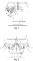
- a suspension device according to the prior art has been shown here in an operating room 1 with an anchoring plate 2 anchored to a support structure 3 or ceiling of this operating room above an operating table 4.
- medical lighting 7, 7 ′ one could have any other electronic system, for example monitoring and control including a screen, a camera.
- monitoring and control including a screen, a camera.
- equipment a fluid distribution system, such as an infusion system, etc.
- each distribution arm comprises a suspension arm 5, 5 'connected on one side to the anchoring plate 2 by a pivot articulation 5A, 5'A and on the other to a spring arm 6, 6' carrying here on its free end a lighting dome 7, 7 ′ intended to form an illumination spot on an area of an operating field, here on the operating table 4.
- the vertical axis XX ' represents the central axis of the anchoring plate 2 which is also the axis of the pivot joint 5A, 5'A at the end of the suspension arms 5, 5'.
- collisions can take place between the two spring arms 6, 6 'of the two distribution arms or between a spring arm 6, 6' and a suspension arm 5, 5 ' from the same distribution arm, or from the other distribution arm
- the suspension device according to the invention has been illustrated in place in the operating room 1 with the operating table 4 aligned vertically with the anchoring plate 2 along its central axis XX '.
- a pivot articulation 11, 11 ′ of a distribution arm is offset from the anchoring plate 2 (from its central axis XX ′) via an offset arm 8, 8 'fixed which is interposed between the anchoring plate 2 and the joint in question.
- a first end of the offset arm 8, 8 ' is linked to the anchoring plate 2 while the other end is linked to the suspension arm 9, 9' via the pivot joint 11, 11 '.
- each offset arm such as 8 or 8 ′ is kept fixed relative to the anchoring plate 2 during a pivoting of the dispensing arm.
- each dispensing arm comprises a suspension arm 9, 9 'connected to the anchoring plate 2 / offset arm 8, 8' by the pivot joint 11, 11 'and a spring arm 10, 10' pivoting at a end of a suspension arm 9, 9 'and having another free end which carries equipment, here on the figure 2 , a medical dome 7, 7 ′.
- the fixed link between an offset arm 8, 8 ′ and the anchoring plate 2 can be of the sheath / collar type with the possibility of disassembly and height adjustment before and after a medical operation.
- This fixed link maintains the offset arm 8, 8 ′ in a fixed position relative to the anchoring plate 2 during a movement in movement of the dispensing arm.
- Such an offset arm 8, 8 ′ can perfectly be installed on an existing anchor plate 2, in place of a suspension arm.
- these two offset arms 8, 8' could be arranged in a V with a fixed angle. In both cases, they could also be superimposed on each other.
- the invention extends to configurations of a suspension device with more than two pivoting distribution arms 11, 11 ′ offset from the anchoring plate 2.
- the two lighting domes 7, 7 ′ face each other under the offset arms 8.8 ′.
- each suspension arm 9, 9 ' is shorter than an offset arm 8, 8'.
- each distribution arm (suspension arm 9, 9 'with spring arm 10, 10') is shorter than an offset arm 8, 8 'which means that the spring arms 10, 10' cannot colliding with each other because each spring arm 10, 10 ′ with a lighting dome 7, 7 ′ has its own movement zone above the operating field.
- each lighting dome 7, 7 ′ can be positioned on both sides of the operating table 4, either at the feet or at the head of a patient lying on the table.
- the figure 4 shows a schematic perspective view of the suspension device according to the invention with double offset arm 8, 8 '.
- each offset arm 8, 8 ′ is fixedly connected to the anchoring plate 2.
- the connection can be removable or adjustable, for example in height along the axis XX ′.
- two connections offset from the center of the plate 2 of the sheath / collar type have been illustrated.
- Each pivot joint 11, 11 ' which connects a suspension arm 9, 9' to an offset arm 8, 8 'can also be of the sheath / collar or hub type with the possibility of vertical adjustment along the axis XX'.
- the articulation 12, 12 'between a suspension arm 9, 9' and a spring arm 10, 10 ' makes it possible to tilt the suspension arm 9, 9' downwards or upwards and therefore to move away or bring the dome 7, 7 'closer to the operating table 4.
- This articulation 12, 12' can also be a pivot articulation with horizontal axis of rotation.
- each arm of suspension 9, 9 ' is shorter than an offset arm 8, 8'.
- the equipment here is a lighting dome 7, 7 'with a lighting axis arranged in the center of the lighting dome 7, 7'.
- the lighting axis of the lighting dome 7, 7 ′ must preferably be able to exceed the axis XX ′ of the anchoring plate 2 d '' about 800 mm to +/- 300 mm.
- the offset arm 8, 8 ′ preferably has a length equivalent to at least the sum of the length of the spring arm 10, 10 ′ and of the lighting dome up to its lighting axis.
- the axis XX 'of the anchoring plate 2 of the figure 4 is free to accommodate other equipment to be suspended.
- an offset arm 8, 8 'to the suspension device is an artificial offset of the equipment 7, 7' in an operating room 1.
- This artificial offset of the equipment 7, 7 ′ is compatible with the centralized anchoring system in an operating room 1.
- This artificial offset of the equipment 7, 7 ′ in an operating room 1 is compatible with laminar flows initially planned for centralized anchoring.
- the suspension device according to the invention makes it possible to reduce the forces associated with the handling of the equipment 7, 7 'fixed to the spring arm 10, 10', as is known with the suspension devices in position 9-3.
- the offset arms 8, 8 ′ in mutual alignment on either side of a central point of the anchoring plate 2 as illustrated in the figure 2 could be replaced by a single 8 "offset arm fixed in the middle by a single link on the central point of the anchor plate 2 as shown in the figure 5 .
- the attachment can be of the sheath / collar type to also allow mounting, dismounting and height adjustment of the single 8 "offset arm before and after a medical operation.
Landscapes
- Engineering & Computer Science (AREA)
- General Engineering & Computer Science (AREA)
- Health & Medical Sciences (AREA)
- Life Sciences & Earth Sciences (AREA)
- Mechanical Engineering (AREA)
- Surgery (AREA)
- General Health & Medical Sciences (AREA)
- Animal Behavior & Ethology (AREA)
- Veterinary Medicine (AREA)
- Public Health (AREA)
- Molecular Biology (AREA)
- Biomedical Technology (AREA)
- Oral & Maxillofacial Surgery (AREA)
- Medical Informatics (AREA)
- Heart & Thoracic Surgery (AREA)
- Nuclear Medicine, Radiotherapy & Molecular Imaging (AREA)
- Pathology (AREA)
- Nursing (AREA)
- Accommodation For Nursing Or Treatment Tables (AREA)
- Microscoopes, Condenser (AREA)
Description
- Le domaine de l'invention concerne les dispositifs de suspension permettant de suspendre des équipements sous une structure support, comprenant une platine d'ancrage destinée à être ancrée axialement à la structure support, deux bras de distribution réglables en débattement destinés à porter les équipements, chaque bras de distribution comprenant un bras de suspension ayant une extrémité articulée à la platine d'ancrage par l'intermédiaire d'une articulation pivot permettant une rotation du bras de suspension dans un plan horizontal et un bras ressort articulé à l'autre extrémité du bras de suspension pour être inclinable verticalement par rapport au bras de suspension, l'autre extrémité du bras ressort portant un équipement.
- En milieu médical, notamment dans une salle opératoire, des équipements médicaux tels que des dispositifs d'éclairage, des dispositifs de surveillance ou de contrôle avec écrans et caméras, des fluides médicaux sont généralement suspendus à une structure support via un dispositif de suspension accroché à une platine d'ancrage ancrée à la structure support, tel qu'un plafond. Le dispositif de suspension permet de répartir les multiples équipements par des bras de distribution réglables autour d'une zone d'utilisation, le plus souvent une table d'opération centrée dans la salle opératoire. Un bras de distribution comprend généralement un bras de suspension relié d'un coté à la platine d'ancrage et de l'autre à un bras ressort qui porte un ou plusieurs équipements médicaux.
- On connaît du document
FR 2662779 EP 1239805 ,EP 1442246 ,EP1478876 des dispositifs de suspension médicaux supportant un ou plusieurs équipements avec des bras de distribution articulés. Ces documents décrivent en outre des dispositifs de suspension accrochés à une platine d'ancrage positionnée le plus souvent au centre de la salle opératoire, de telle sorte que la table opératoire est alignée avec la platine d'ancrage. - Il est reconnu par le personnel médical qu'au cours d'une opération le déplacement des bras articulés portant les multiples équipements peut induire des collisions entre des équipements fixes ou mobiles. Les collisions peuvent être du type le bras ressort entrant en contact avec son bras de suspension, ou encore une coupole d'éclairage du dispositif d'éclairage fixé à un bras articulé cognant un bras de suspension ou un bras ressort d'un autre bras articulé.
- De plus même si le personnel médical est souvent satisfait de la fonction primaire des dispositifs de suspension, il se plaint souvent des difficultés de positionnement avec des efforts importants à fournir pour la manipulation des dispositifs de suspension, et il mentionne aussi une dérive possible des différents équipements. Un autre grief du personnel médical concerne des positionnements d'équipements, tels que des dispositifs d'éclairage, impossibles à atteindre sur la zone d'utilisation, créant ainsi des singularités sur la zone d'utilisation.
- Afin de répondre en partie à ces inconvénients, des fabricants de dispositifs de suspension d'équipements médicaux dans une salle opératoire proposent d'ancrer des dispositifs de suspension sur les cotés de la structure support de la salle opératoire, de sorte que des ancrages soient en position 9-3 ou 12-6 (ces chiffres correspondant au positionnement des aiguilles d'une montre) par rapport à la table opératoire positionnée au centre de la salle opératoire. Les installations avec des ancrages de type 9-3 semblent apporter une meilleure utilisation de l'espace tout en étant compatible avec les flux laminaires qui sont prévus initialement pour des ancrages centralisés.
- Néanmoins, les salles opératoires ne sont pas toujours compatibles pour de telles installations qui nécessitent plusieurs points d'ancrage, les salles conventionnelles permettant uniquement un ancrage centralisé de dispositif de suspension.
- Le document
FR 2974473 - Le but de l'invention est donc de remédier à ces inconvénients en proposant un dispositif de suspension présentant les avantages d'un agencement 9-3 des dispositifs de suspension compatible avec un ancrage centralisé d'une salle opératoire.
- A cet effet, l'invention a pour objet un dispositif de suspension permettant de suspendre des équipements sous une structure support, comprenant une platine d'ancrage destinée à être ancrée axialement à la structure support, deux bras de distribution réglables en débattement destinés à porter les équipements , chaque bras de distribution comprenant un bras de suspension ayant une extrémité articulée à la platine d'ancrage par l'intermédiaire d'une articulation pivot permettant une rotation du bras de suspension dans un plan horizontal et un bras ressort articulé à l'autre extrémité du bras de suspension pour être inclinable verticalement par rapport au bras de suspension, l'autre extrémité du bras ressort portant un équipement, caractérisé en ce que chaque articulation pivot d'un bras de suspension est disposée à l'extrémité d'un bras de déport pour être déportée horizontalement d'une certaine distance de déport par rapport à l'axe de la platine d'ancrage qui est supérieure à la longueur du bras de suspension et en ce qu'il comprend en outre un moyen de liaison qui solidarise de manière fixe le bras de déport à l'axe de la platine d'ancrage de telle manière qu'il reste fixe par rapport à la platine d'ancrage pendant un pivotement du bras de distribution dans le plan horizontal.
- Le dispositif de suspension selon l'invention peut ainsi avantageusement présenter les particularités suivantes :
- il comprend deux bras de déport qui sont en alignement mutuel de part et d'autre d'un point central de la platine d'ancrage ;
- l'équipement est un équipement médical.
- Avec cet agencement, il est possible de créer un déport artificiel des équipements portés par les bras de distributions (le bras de suspension et le bras ressort) à partir d'un ancrage centralisé afin d'obtenir une configuration de type 9-3 connue pour limiter les collisions et le nombre de position singulière dans la zone d'utilisation, tout en étant compatible avec les flux laminaires d'une salle opératoire à ancrage centralisé.
- Ce déport artificiel est une solution économique et rapide de modification de l'agencement des équipements dans la salle opératoire autour de la zone d'utilisation car il est compatible avec une installation centralisée existante, il permet de réduire le nombre d'ancrage et de diminuer le nombre d'articulation tournante et/ou pivotante par rapport aux dispositifs de suspensions de l'état de l'art.
- La présente invention sera mieux comprise et d'autres avantages apparaîtront à la lecture de la description détaillée de plusieurs modes de réalisation pris à titre d'exemples nullement limitatifs et illustrés par les dessins annexés dans lesquels :
- la
figure 1 est une représentation schématique d'un dispositif de suspension selon l'art antérieur dans une salle opératoire ; - la
figure 2 est une représentation schématique d'un dispositif de suspension selon l'invention dans une salle opératoire ; - les
figures 3A et 3B est une représentation schématique d'une première et d'une seconde configuration du dispositif de suspension selon l'invention ; - la
figure 4 est une vue en perspective schématique du dispositif de suspension selon l'invention dans une salle opératoire. - la
figure 5 est une vue en perspective schématique du dispositif de suspension selon un autre mode de réalisation de l'invention dans une salle opératoire. - En référence à la
figure 1 , on a représenté un dispositif de suspension selon l'art antérieur ici dans une salle opératoire 1 avec une platine d'ancrage 2 ancrée à une structure support 3 ou plafond de cette salle opératoire au-dessus d'une table d'opération 4. - Au cours d'une opération médicale, le personnel médical a l'habitude d'aligner à l'aplomb le centre de la table d'opération 4 avec la platine d'ancrage 2.
- Sur la
figure 1 , on a illustré deux bras de distribution réglables articulés chacun par rapport à la platine d'ancrage 2, chacun des bras de distribution portant à leur extrémité libre un équipement 7, 7' médical, ici un éclairage médical. - A la place d'un éclairage médical 7, 7', on pourrait avoir tout autre système électronique, par exemple de surveillance et de contrôle incluant un écran, une caméra. On pourrait avoir comme équipement, un système de distribution d'un fluide, comme un système de perfusion, etc.
- Classiquement, chaque bras de distribution comprend un bras de suspension 5, 5' relié d'un coté à la platine d'ancrage 2 par une articulation pivot 5A, 5'A et de l'autre à un bras ressort 6, 6' portant ici sur son extrémité libre une coupole d'éclairage 7, 7' destinée à former une tache d'éclairement sur une zone d'un champ opératoire, ici sur la table d'opération 4.
- On a représenté par l'axe vertical XX' l'axe central de la platine d'ancrage 2 qui est aussi l'axe de l'articulation pivot 5A, 5'A à l'extrémité des bras de suspension 5, 5'.
- Comme indiqué plus haut, avec ce type de dispositif de suspension, des collisions peuvent avoir lieu entre les deux bras ressorts 6, 6' des deux bras de distribution ou entre un bras ressort 6, 6' et un bras de suspension 5, 5' du même bras de distribution, ou de l'autre bras de distribution.
- On a matérialisé par des cercles en pointillés sur la
figure 1 les zones de collision où les collisions sont les plus fréquentes. - A partir de la
figure 1 , on comprend par exemple que le bras ressort 6' interfère avec le bras de suspension 5' du même bras de distribution du fait que le point le plus haut du bras ressort 6' est plus haut que le point le plus bas du bras de suspension 5'. La coupole d'éclairage 7' peut aussi entrer en collision avec le bras de suspension 5'. - Sur la
figure 2 , on a illustré le dispositif de suspension selon l'invention en place dans la salle opératoire 1 avec la table d'opération 4 alignée verticalement avec la platine d'ancrage 2 suivant son axe central XX'. - Dans le dispositif de suspension selon l'invention, une articulation pivot 11, 11' d'un bras de distribution est déportée de la platine d'ancrage 2 (de son axe central XX') par l'intermédiaire d'un bras de déport 8, 8' fixe qui est interposé entre la platine d'ancrage 2 et l'articulation en question. Une première extrémité du bras de déport 8, 8' est liée à la platine d'ancrage 2 tandis que l'autre extrémité est liée au bras de suspension 9, 9' via l'articulation pivot 11, 11'.
- Sur cette
figure 2 , on a représenté deux bras de déport 8, 8' en alignement mutuel de part et d'autre d'un point central de la platine d'ancrage 2. - Au cours de l'opération médicale, chaque bras de déport tel que 8 ou 8' est maintenu fixe par rapport à la platine d'ancrage 2 pendant un pivotement du bras de distribution.
- Comme représenté sur la
figure 2 , chaque bras de distribution comporte un bras de suspension 9, 9' relié à la platine d'ancrage 2 / bras de déport 8, 8' par l'articulation pivot 11, 11' et un bras ressort 10, 10' pivotant à une extrémité d'un bras de suspension 9, 9' et ayant une autre extrémité libre qui porte un équipement, ici sur lafigure 2 , une coupole d'éclairage 7, 7' médical. - La liaison fixe entre un bras de déport 8, 8' et la platine d'ancrage 2 peut être du type fourreau/collier avec possibilité de démontage et de réglage en hauteur avant et après une opération médicale. Cette liaison fixe maintient le bras de déport 8, 8' en position fixe par rapport à la platine d'ancrage 2 pendant un mouvement en déplacement du bras de distribution.
- Un tel bras de déport 8, 8' peut parfaitement être installé sur une platine d'ancrage 2 existante, en lieu et place d'un bras de suspension.
- A la place d'avoir deux bras de déport 8,8' en alignement mutuel, ces deux bras de déport 8, 8' pourraient être disposés en V avec un angle fixe. Dans les deux cas, ils pourraient aussi être superposés l'un par rapport à l'autre.
- L'invention s'étend à des configurations d'un dispositif de suspension avec plus de deux bras de distribution à articulation pivot 11, 11' déportée de la platine d'ancrage 2.
- Sur la
figure 3A , les deux bras de suspension 9, 9' avec les deux bras ressort 10, 10' sont déployés suivant une configuration 9-3 sous les bras de déport 8,8'. - Les deux coupoles d'éclairage 7, 7' se font face sous les bras de déport 8,8'.
- On voit sur cette figure, mais aussi sur la
figure 2 , que chaque bras de suspension 9, 9' est plus court qu'un bras de déport 8, 8'. - Dans ce cas, il n'y a pas de risque de collision entre les deux bras de suspension 9, 9' mais en plus on peut déplacer la coupole d'éclairage 7, 7' sur une zone plus vaste qu'avec un dispositif classique de suspension en laissant moins de zones de singularités sur le champ opératoire.
- Par ailleurs, chaque bras de distribution (bras de suspension 9, 9' avec bras ressort 10, 10') est plus court qu'un bras de déport 8, 8' ce qui fait que les bras ressort 10, 10' ne peuvent pas entrer mutuellement en collision car chaque bras ressort 10, 10' avec une coupole d'éclairage 7, 7' a sa propre zone de mouvement au dessus du champ opératoire.
- Il n'y a donc aucun risque de collision entre un bras ressort 10, 10' et un bras de suspension 9, 9' ou entre les coupoles d'éclairage 7, 7' entre elles.
- Sur la
figure 3B , on a un dispositif de suspension selon l'invention à double bras de distribution, avec deux bras de déport 8, 8' en alignement mutuel, chaque bras de déport 8, 8' étant plus long qu'un bras de suspension 9, 9'. Toutefois, comme visible sur cettefigure 3B , les bras ressorts 10,10' se croisent en se faisant face. - Avec cet agencement, chaque coupole d'éclairage 7, 7' peut être positionnée des deux cotés de la table opératoire 4, soit aux pieds soit à la tête d'un patient allongé sur la table.
- La
figure 4 montre une vue schématique en perspective du dispositif de suspension selon l'invention à double bras de déport 8, 8'. - Comme déjà indiqué ci-dessus, chaque bras de déport 8, 8' est connecté fixement à la platine d'ancrage 2. La connexion peut être démontable ou réglable, par exemple en hauteur suivant l'axe XX'. Sur la
figure 4 , on a illustré deux connexions décalées du centre de la platine 2 du type fourreau/collier. - Chaque articulation pivot 11, 11' qui relie un bras de suspension 9, 9' à un bras de déport 8, 8' peut aussi être du type fourreau/collier ou moyeu avec possibilité de réglage vertical suivant l'axe XX'.
- L'articulation 12, 12' entre un bras de suspension 9, 9' et un bras ressort 10, 10' permet d'incliner vers le bas ou vers le haut le bras de suspension 9, 9' et donc d'éloigner ou de rapprocher la coupole 7, 7' de la table d'opération 4. Cette articulation 12, 12' peut aussi être une articulation pivot à axe de rotation horizontale.
- De préférence, afin d'éviter les risques de collision entre les deux bras de suspension 9, 9', ces bras de suspension 9, 9' ne doivent pas pouvoir atteindre l'axe central XX' de la platine d'ancrage 2. Ainsi chaque bras de suspension 9, 9' est plus court qu'un bras de déport 8, 8' .
- L'équipement est ici une coupole d'éclairage 7, 7' avec un axe d'éclairage agencé au centre de la coupole d'éclairage 7, 7'. Afin de couvrir l'ensemble de la zone d'utilisation du champ opératoire, l'axe d'éclairage de la coupole d'éclairage 7, 7' doit de préférence pouvoir dépasser l'axe XX' de la platine d'ancrage 2 d'environ 800 mm à +/- 300 mm.
- Le bras de déport 8, 8' a de préférence une longueur équivalente à au moins la somme de la longueur du bras ressort 10, 10' et de la coupole d'éclairage jusqu'à son axe d'éclairage.
- Il est à noter que l'axe XX' de la platine d'ancrage 2 de la
figure 4 est libre pour accueillir d'autres équipements à mettre en suspension. - On comprend que selon l'invention, l'ajout d'un bras de déport 8, 8' au dispositif de suspension est un déport artificiel des équipements 7, 7' dans une salle opératoire 1.
- Ce déport artificiel des équipements 7, 7' est compatible au système d'ancrage centralisé dans une salle opératoire 1.
- Ce déport artificiel permet de configurer facilement et de façon économique une salle opératoire 1 avec des dispositifs de suspension comme s'ils se trouvaient en position type 9-3 : un seul point d'ancrage est nécessaire et il y a suppression d'articulations tournantes.
- Cet agencement avec déport artificiel présente tous les avantages d'une installation 9-3. Ces avantages connus sont une limitation les collisions, un déplacement des équipements 7, 7' dans des positions non atteignables avec des dispositifs de suspension de l'art antérieur centrés sur la table opératoire 4, limitant ainsi les singularités autour de la zone d'utilisation.
- Ce déport artificiel des équipements 7, 7' dans une salle opératoire 1 est compatible avec des flux laminaires prévus initialement pour un ancrage centralisé.
- Le dispositif de suspension selon l'invention permet de diminuer les efforts liés à la manipulation des équipements 7, 7' fixés au bras ressort 10, 10', comme cela est connu avec les dispositifs de suspension en position 9-3.
- Il va de soi que la présente invention ne saurait être limitée à la description qui précède d'un de ses modes de réalisation, susceptibles de subir quelques modifications sans pour autant sortir du cadre de l'invention.
- Par exemple, selon un autre mode de réalisation, les bras de déport 8, 8' en alignement mutuel de part et d'autre d'un point central de la platine d'ancrage 2 tels illustrés sur la
figure 2 pourrait être remplacé par un bras de déport 8" unique fixé en son milieu par une liaison unique sur point central de la platine d'ancrage 2 comme représenté sur lafigure 5 . La fixation peut être du type fourreau/collier pour également permettre de monter, de démonter et de régler en hauteur le bras de déport 8" unique avant et après une opération médicale.
Claims (3)
- Dispositif de suspension permettant de suspendre des équipements (7,7') sous une structure support (3), comprenant une platine d'ancrage (2) destinée à être ancrée axialement (XX') à ladite structure support (3), deux bras de distribution (9,10,9',10') réglables en débattement destinés à porter lesdits équipements (7,7'), chaque bras de distribution (9,10,9',10') comprenant un bras de suspension (9,9') ayant une extrémité articulée à ladite platine d'ancrage par l'intermédiaire d'une articulation pivot (11,11') permettant une rotation dudit bras de suspension (9,9') dans un plan horizontal et un bras ressort (10,10') articulé à l'autre extrémité dudit bras de suspension (9,9') pour être inclinable verticalement par rapport audit bras de suspension (9,9'), l'autre extrémité dudit bras ressort (10,10') portant un équipement (7,7'), caractérisé en ce que chaque articulation pivot (11,11') d'un bras de suspension (9,9') est disposée à l'extrémité d'un bras de déport (8,8' ; 8") pour être déportée horizontalement d'une certaine distance de déport par rapport audit axe (XX') de ladite platine d'ancrage (2) qui est supérieure à la longueur dudit bras de suspension (9,9'), et en ce qu'il comprend en outre un moyen de liaison qui solidarise de manière fixe ledit bras de déport (8,8'; 8") audit axe (XX') de ladite platine d'ancrage (2) de telle manière qu'il reste fixe par rapport à ladite platine d'ancrage (2) pendant un pivotement dudit bras de distribution (9,10,9',10') dans ledit plan horizontal.
- Dispositif de suspension selon la revendication 1, caractérisé en ce qu'il comprend deux bras de déport (8,8') qui sont en alignement mutuel de part et d'autre d'un point central de ladite platine d'ancrage (2).
- Dispositif de suspension selon l'une des revendications précédentes, caractérisé en ce que ledit équipement (7,7') est un équipement médical.
Applications Claiming Priority (2)
| Application Number | Priority Date | Filing Date | Title |
|---|---|---|---|
| FR1650394A FR3046828B1 (fr) | 2016-01-19 | 2016-01-19 | Dispositif de suspension medical a bras de deport |
| PCT/FR2017/050102 WO2017125677A1 (fr) | 2016-01-19 | 2017-01-18 | Dispositif de suspension medical a bras de deport |
Publications (2)
| Publication Number | Publication Date |
|---|---|
| EP3405715A1 EP3405715A1 (fr) | 2018-11-28 |
| EP3405715B1 true EP3405715B1 (fr) | 2020-02-19 |
Family
ID=57184518
Family Applications (1)
| Application Number | Title | Priority Date | Filing Date |
|---|---|---|---|
| EP17706540.6A Active EP3405715B1 (fr) | 2016-01-19 | 2017-01-18 | Dispositif de suspension medical a bras de deport |
Country Status (6)
| Country | Link |
|---|---|
| US (1) | US10451217B2 (fr) |
| EP (1) | EP3405715B1 (fr) |
| JP (1) | JP6665297B2 (fr) |
| CN (1) | CN108474513B (fr) |
| FR (1) | FR3046828B1 (fr) |
| WO (1) | WO2017125677A1 (fr) |
Families Citing this family (5)
| Publication number | Priority date | Publication date | Assignee | Title |
|---|---|---|---|---|
| EP3646839A1 (fr) | 2018-11-05 | 2020-05-06 | Ondal Medical Systems GmbH | Système de bras de support pour un appareil médical, procédé de fonctionnement d'un système de bras de support ainsi que procédé de construction d'un système de bras de support |
| EP3927273B1 (fr) | 2019-02-22 | 2023-01-04 | American Sterilizer Company | Plaque de montage pour système de suspension de dispositif médical |
| US11320090B2 (en) * | 2019-11-21 | 2022-05-03 | Oasys Healthcare Corporation | Arm linkage for device bearing spring arms |
| CN113967074B (zh) * | 2020-07-23 | 2025-11-18 | 北京术锐机器人股份有限公司 | 手术机器人体外定位臂组及含该臂组的手术机器人系统 |
| US11852281B2 (en) | 2021-12-09 | 2023-12-26 | Justin T. Wieczorek | Rotating header assembly |
Family Cites Families (21)
| Publication number | Priority date | Publication date | Assignee | Title |
|---|---|---|---|---|
| FR2662779B3 (fr) * | 1990-05-31 | 1992-05-07 | Lefebvre Alain | Suspension plafonniere pour la fixation d'un televiseur ou tout autre appareil de forme similaire. |
| US6012821A (en) * | 1998-03-30 | 2000-01-11 | Hill-Rom, Inc. | Support arm for surgical light apparatus |
| US6328458B1 (en) * | 1998-03-30 | 2001-12-11 | Hill-Rom Services, Inc. | Support arm for surgical light apparatus |
| DE50014939D1 (de) * | 1999-07-03 | 2008-03-20 | Leica Microsystems | Deckenstativ |
| US6466432B1 (en) * | 1999-07-12 | 2002-10-15 | Frank Beger | Instrument and service unit for a surgical operating area |
| DE19945081C2 (de) | 1999-09-21 | 2003-06-18 | Heraeus Med Gmbh | Deckengestützte Aufhängung für ein Gerät, insbesondere Operationsleuchte |
| CA2395377C (fr) | 1999-12-23 | 2008-02-19 | Hill-Rom Services, Inc. | Systeme de salle d'operation |
| DE10116495C1 (de) * | 2001-04-03 | 2002-10-17 | Draeger Medical Ag | Deckenstativ für eine medizinische Leuchte |
| AU2002354031B2 (en) | 2001-11-05 | 2007-08-30 | American Sterilizer Company | Medical suspension system with two spindles |
| AU2003217784C1 (en) | 2002-02-25 | 2006-04-06 | American Sterilizer Company | Ambient lighting system for surgical lights |
| ES2279102T3 (es) * | 2002-02-25 | 2007-08-16 | Steris Inc. | Sistema de freno de articulacion progresivo ajustable. |
| ES2250878T3 (es) | 2002-02-25 | 2006-04-16 | Steris Inc. | Sistema de suspension quirurgica. |
| US6695270B1 (en) * | 2002-08-15 | 2004-02-24 | Ole Falk Smed | Flat panel display system |
| JP4668581B2 (ja) * | 2004-10-27 | 2011-04-13 | オリンパス株式会社 | 手術用顕微鏡 |
| FR2878019B1 (fr) * | 2004-11-17 | 2007-05-18 | Alm Sa | Poteau central de distribution, support et procede de fabrication correspondants. |
| TWM327970U (en) * | 2007-10-02 | 2008-03-01 | Tien-Sheng Chen | Surgical operation illumination system with photographic recorder and lighting function |
| CN201253260Y (zh) * | 2008-09-25 | 2009-06-10 | 浏阳太阳龙医疗科技有限公司 | 一种电动升降医用悬挂装置 |
| US8905204B2 (en) * | 2010-06-10 | 2014-12-09 | Amico Clinical Solutions | Roller bearing having an electric solenoid powered brake |
| FR2974473B1 (fr) * | 2011-04-19 | 2013-11-08 | Maquet S A | Dispositif de surveillance, utilisation d'un tel dispositif de surveillance et installation d'operation comprenant un tel dispositif de surveillance |
| CN103542337B (zh) * | 2012-07-11 | 2016-06-29 | 谭荣兴 | 自动手术照明装置及手术自动照明控制方法 |
| JP6521982B2 (ja) * | 2013-09-20 | 2019-05-29 | キャンプレックス インコーポレイテッド | 手術可視化システム及びディスプレイ |
-
2016
- 2016-01-19 FR FR1650394A patent/FR3046828B1/fr not_active Expired - Fee Related
-
2017
- 2017-01-18 JP JP2018527782A patent/JP6665297B2/ja not_active Expired - Fee Related
- 2017-01-18 US US15/777,027 patent/US10451217B2/en active Active
- 2017-01-18 CN CN201780007079.2A patent/CN108474513B/zh not_active Expired - Fee Related
- 2017-01-18 EP EP17706540.6A patent/EP3405715B1/fr active Active
- 2017-01-18 WO PCT/FR2017/050102 patent/WO2017125677A1/fr not_active Ceased
Non-Patent Citations (1)
| Title |
|---|
| None * |
Also Published As
| Publication number | Publication date |
|---|---|
| JP6665297B2 (ja) | 2020-03-13 |
| CN108474513B (zh) | 2020-02-11 |
| FR3046828A1 (fr) | 2017-07-21 |
| WO2017125677A1 (fr) | 2017-07-27 |
| US10451217B2 (en) | 2019-10-22 |
| US20180372270A1 (en) | 2018-12-27 |
| CN108474513A (zh) | 2018-08-31 |
| FR3046828B1 (fr) | 2019-09-20 |
| JP2019508076A (ja) | 2019-03-28 |
| EP3405715A1 (fr) | 2018-11-28 |
Similar Documents
| Publication | Publication Date | Title |
|---|---|---|
| FR3046828B1 (fr) | Dispositif de suspension medical a bras de deport | |
| US7303314B2 (en) | Adjustable trim for sloped ceiling recessed downlight | |
| JP3148195U (ja) | モニター支持装置 | |
| CN102017611B (zh) | 平板显示器安装架 | |
| US4448388A (en) | Canopy assembly | |
| JP4866435B2 (ja) | 空間においてユーティリティー荷重物を保持および位置決めするための支持体 | |
| JP6170721B2 (ja) | 吊り下げ支持装置 | |
| JP5903098B2 (ja) | 吊り下げ機とレールとを有する装置 | |
| JP2006184887A (ja) | 構成部品を支持するための適切なデバイス | |
| CA2377965A1 (fr) | Mats d'antennes relais de systeme de radio-telecommunication cellulaire | |
| JP2012125561A (ja) | Ctスキャンフレームに用いられる自己調整軸受 | |
| EP3466863B1 (fr) | Grue à flèche relevable avec dispositif de verrouillage de la flèche en configuration relevée | |
| CN107532670B (zh) | 弹簧承载件 | |
| JP5847486B2 (ja) | 照明器具の吊下装置 | |
| KR101045945B1 (ko) | 디스플레이장치 거치대 | |
| FR2701337A1 (fr) | Support universel de têtes pour la réception multiple de satellites sur une seule antenne parabolique fixe. | |
| WO2017191019A1 (fr) | Flotteur d'éolienne offshore | |
| EP2650584A1 (fr) | Bras articulé notamment pour appareil électrique et une installation pour appareil électrique | |
| KR102042388B1 (ko) | 설치경로와 내진 맞춤형 전신주용 송배전케이블 고정장치 | |
| JP6362848B2 (ja) | 落下防止装置 | |
| EP1813740B1 (fr) | Abri | |
| CA2994477C (fr) | Rotor de giravion incluant un ensemble de plateaux cycliques et deux compas tournants | |
| US20050201110A1 (en) | Hanging light fixture | |
| FR2754600A1 (fr) | Dispositif didactique de mise en evidence de l'effet de coriolis | |
| JP4545657B2 (ja) | 取付金具用回動アタッチメント |
Legal Events
| Date | Code | Title | Description |
|---|---|---|---|
| STAA | Information on the status of an ep patent application or granted ep patent |
Free format text: STATUS: UNKNOWN |
|
| STAA | Information on the status of an ep patent application or granted ep patent |
Free format text: STATUS: THE INTERNATIONAL PUBLICATION HAS BEEN MADE |
|
| PUAI | Public reference made under article 153(3) epc to a published international application that has entered the european phase |
Free format text: ORIGINAL CODE: 0009012 |
|
| STAA | Information on the status of an ep patent application or granted ep patent |
Free format text: STATUS: REQUEST FOR EXAMINATION WAS MADE |
|
| 17P | Request for examination filed |
Effective date: 20180820 |
|
| AK | Designated contracting states |
Kind code of ref document: A1 Designated state(s): AL AT BE BG CH CY CZ DE DK EE ES FI FR GB GR HR HU IE IS IT LI LT LU LV MC MK MT NL NO PL PT RO RS SE SI SK SM TR |
|
| AX | Request for extension of the european patent |
Extension state: BA ME |
|
| DAV | Request for validation of the european patent (deleted) | ||
| DAX | Request for extension of the european patent (deleted) | ||
| GRAP | Despatch of communication of intention to grant a patent |
Free format text: ORIGINAL CODE: EPIDOSNIGR1 |
|
| STAA | Information on the status of an ep patent application or granted ep patent |
Free format text: STATUS: GRANT OF PATENT IS INTENDED |
|
| INTG | Intention to grant announced |
Effective date: 20191017 |
|
| GRAS | Grant fee paid |
Free format text: ORIGINAL CODE: EPIDOSNIGR3 |
|
| GRAA | (expected) grant |
Free format text: ORIGINAL CODE: 0009210 |
|
| STAA | Information on the status of an ep patent application or granted ep patent |
Free format text: STATUS: THE PATENT HAS BEEN GRANTED |
|
| AK | Designated contracting states |
Kind code of ref document: B1 Designated state(s): AL AT BE BG CH CY CZ DE DK EE ES FI FR GB GR HR HU IE IS IT LI LT LU LV MC MK MT NL NO PL PT RO RS SE SI SK SM TR |
|
| REG | Reference to a national code |
Ref country code: CH Ref legal event code: EP |
|
| REG | Reference to a national code |
Ref country code: DE Ref legal event code: R096 Ref document number: 602017011976 Country of ref document: DE |
|
| REG | Reference to a national code |
Ref country code: AT Ref legal event code: REF Ref document number: 1235371 Country of ref document: AT Kind code of ref document: T Effective date: 20200315 |
|
| REG | Reference to a national code |
Ref country code: IE Ref legal event code: FG4D Free format text: LANGUAGE OF EP DOCUMENT: FRENCH |
|
| REG | Reference to a national code |
Ref country code: NL Ref legal event code: MP Effective date: 20200219 |
|
| PG25 | Lapsed in a contracting state [announced via postgrant information from national office to epo] |
Ref country code: RS Free format text: LAPSE BECAUSE OF FAILURE TO SUBMIT A TRANSLATION OF THE DESCRIPTION OR TO PAY THE FEE WITHIN THE PRESCRIBED TIME-LIMIT Effective date: 20200219 Ref country code: FI Free format text: LAPSE BECAUSE OF FAILURE TO SUBMIT A TRANSLATION OF THE DESCRIPTION OR TO PAY THE FEE WITHIN THE PRESCRIBED TIME-LIMIT Effective date: 20200219 Ref country code: NO Free format text: LAPSE BECAUSE OF FAILURE TO SUBMIT A TRANSLATION OF THE DESCRIPTION OR TO PAY THE FEE WITHIN THE PRESCRIBED TIME-LIMIT Effective date: 20200519 |
|
| REG | Reference to a national code |
Ref country code: LT Ref legal event code: MG4D |
|
| PG25 | Lapsed in a contracting state [announced via postgrant information from national office to epo] |
Ref country code: GR Free format text: LAPSE BECAUSE OF FAILURE TO SUBMIT A TRANSLATION OF THE DESCRIPTION OR TO PAY THE FEE WITHIN THE PRESCRIBED TIME-LIMIT Effective date: 20200520 Ref country code: BG Free format text: LAPSE BECAUSE OF FAILURE TO SUBMIT A TRANSLATION OF THE DESCRIPTION OR TO PAY THE FEE WITHIN THE PRESCRIBED TIME-LIMIT Effective date: 20200519 Ref country code: HR Free format text: LAPSE BECAUSE OF FAILURE TO SUBMIT A TRANSLATION OF THE DESCRIPTION OR TO PAY THE FEE WITHIN THE PRESCRIBED TIME-LIMIT Effective date: 20200219 Ref country code: LV Free format text: LAPSE BECAUSE OF FAILURE TO SUBMIT A TRANSLATION OF THE DESCRIPTION OR TO PAY THE FEE WITHIN THE PRESCRIBED TIME-LIMIT Effective date: 20200219 Ref country code: IS Free format text: LAPSE BECAUSE OF FAILURE TO SUBMIT A TRANSLATION OF THE DESCRIPTION OR TO PAY THE FEE WITHIN THE PRESCRIBED TIME-LIMIT Effective date: 20200619 Ref country code: SE Free format text: LAPSE BECAUSE OF FAILURE TO SUBMIT A TRANSLATION OF THE DESCRIPTION OR TO PAY THE FEE WITHIN THE PRESCRIBED TIME-LIMIT Effective date: 20200219 |
|
| PG25 | Lapsed in a contracting state [announced via postgrant information from national office to epo] |
Ref country code: NL Free format text: LAPSE BECAUSE OF FAILURE TO SUBMIT A TRANSLATION OF THE DESCRIPTION OR TO PAY THE FEE WITHIN THE PRESCRIBED TIME-LIMIT Effective date: 20200219 |
|
| PG25 | Lapsed in a contracting state [announced via postgrant information from national office to epo] |
Ref country code: PT Free format text: LAPSE BECAUSE OF FAILURE TO SUBMIT A TRANSLATION OF THE DESCRIPTION OR TO PAY THE FEE WITHIN THE PRESCRIBED TIME-LIMIT Effective date: 20200712 Ref country code: SK Free format text: LAPSE BECAUSE OF FAILURE TO SUBMIT A TRANSLATION OF THE DESCRIPTION OR TO PAY THE FEE WITHIN THE PRESCRIBED TIME-LIMIT Effective date: 20200219 Ref country code: EE Free format text: LAPSE BECAUSE OF FAILURE TO SUBMIT A TRANSLATION OF THE DESCRIPTION OR TO PAY THE FEE WITHIN THE PRESCRIBED TIME-LIMIT Effective date: 20200219 Ref country code: SM Free format text: LAPSE BECAUSE OF FAILURE TO SUBMIT A TRANSLATION OF THE DESCRIPTION OR TO PAY THE FEE WITHIN THE PRESCRIBED TIME-LIMIT Effective date: 20200219 Ref country code: DK Free format text: LAPSE BECAUSE OF FAILURE TO SUBMIT A TRANSLATION OF THE DESCRIPTION OR TO PAY THE FEE WITHIN THE PRESCRIBED TIME-LIMIT Effective date: 20200219 Ref country code: LT Free format text: LAPSE BECAUSE OF FAILURE TO SUBMIT A TRANSLATION OF THE DESCRIPTION OR TO PAY THE FEE WITHIN THE PRESCRIBED TIME-LIMIT Effective date: 20200219 Ref country code: ES Free format text: LAPSE BECAUSE OF FAILURE TO SUBMIT A TRANSLATION OF THE DESCRIPTION OR TO PAY THE FEE WITHIN THE PRESCRIBED TIME-LIMIT Effective date: 20200219 Ref country code: CZ Free format text: LAPSE BECAUSE OF FAILURE TO SUBMIT A TRANSLATION OF THE DESCRIPTION OR TO PAY THE FEE WITHIN THE PRESCRIBED TIME-LIMIT Effective date: 20200219 Ref country code: RO Free format text: LAPSE BECAUSE OF FAILURE TO SUBMIT A TRANSLATION OF THE DESCRIPTION OR TO PAY THE FEE WITHIN THE PRESCRIBED TIME-LIMIT Effective date: 20200219 |
|
| REG | Reference to a national code |
Ref country code: AT Ref legal event code: MK05 Ref document number: 1235371 Country of ref document: AT Kind code of ref document: T Effective date: 20200219 |
|
| REG | Reference to a national code |
Ref country code: DE Ref legal event code: R097 Ref document number: 602017011976 Country of ref document: DE |
|
| PLBE | No opposition filed within time limit |
Free format text: ORIGINAL CODE: 0009261 |
|
| STAA | Information on the status of an ep patent application or granted ep patent |
Free format text: STATUS: NO OPPOSITION FILED WITHIN TIME LIMIT |
|
| 26N | No opposition filed |
Effective date: 20201120 |
|
| PG25 | Lapsed in a contracting state [announced via postgrant information from national office to epo] |
Ref country code: AT Free format text: LAPSE BECAUSE OF FAILURE TO SUBMIT A TRANSLATION OF THE DESCRIPTION OR TO PAY THE FEE WITHIN THE PRESCRIBED TIME-LIMIT Effective date: 20200219 |
|
| PG25 | Lapsed in a contracting state [announced via postgrant information from national office to epo] |
Ref country code: PL Free format text: LAPSE BECAUSE OF FAILURE TO SUBMIT A TRANSLATION OF THE DESCRIPTION OR TO PAY THE FEE WITHIN THE PRESCRIBED TIME-LIMIT Effective date: 20200219 Ref country code: SI Free format text: LAPSE BECAUSE OF FAILURE TO SUBMIT A TRANSLATION OF THE DESCRIPTION OR TO PAY THE FEE WITHIN THE PRESCRIBED TIME-LIMIT Effective date: 20200219 |
|
| PG25 | Lapsed in a contracting state [announced via postgrant information from national office to epo] |
Ref country code: MC Free format text: LAPSE BECAUSE OF FAILURE TO SUBMIT A TRANSLATION OF THE DESCRIPTION OR TO PAY THE FEE WITHIN THE PRESCRIBED TIME-LIMIT Effective date: 20200219 |
|
| REG | Reference to a national code |
Ref country code: CH Ref legal event code: PL |
|
| PG25 | Lapsed in a contracting state [announced via postgrant information from national office to epo] |
Ref country code: LU Free format text: LAPSE BECAUSE OF NON-PAYMENT OF DUE FEES Effective date: 20210118 |
|
| REG | Reference to a national code |
Ref country code: BE Ref legal event code: MM Effective date: 20210131 |
|
| PG25 | Lapsed in a contracting state [announced via postgrant information from national office to epo] |
Ref country code: CH Free format text: LAPSE BECAUSE OF NON-PAYMENT OF DUE FEES Effective date: 20210131 Ref country code: LI Free format text: LAPSE BECAUSE OF NON-PAYMENT OF DUE FEES Effective date: 20210131 |
|
| PG25 | Lapsed in a contracting state [announced via postgrant information from national office to epo] |
Ref country code: IE Free format text: LAPSE BECAUSE OF NON-PAYMENT OF DUE FEES Effective date: 20210118 |
|
| PG25 | Lapsed in a contracting state [announced via postgrant information from national office to epo] |
Ref country code: BE Free format text: LAPSE BECAUSE OF NON-PAYMENT OF DUE FEES Effective date: 20210131 |
|
| PGFP | Annual fee paid to national office [announced via postgrant information from national office to epo] |
Ref country code: GB Payment date: 20221214 Year of fee payment: 7 Ref country code: FR Payment date: 20221216 Year of fee payment: 7 |
|
| PGFP | Annual fee paid to national office [announced via postgrant information from national office to epo] |
Ref country code: IT Payment date: 20230113 Year of fee payment: 7 Ref country code: DE Payment date: 20221215 Year of fee payment: 7 |
|
| PG25 | Lapsed in a contracting state [announced via postgrant information from national office to epo] |
Ref country code: CY Free format text: LAPSE BECAUSE OF FAILURE TO SUBMIT A TRANSLATION OF THE DESCRIPTION OR TO PAY THE FEE WITHIN THE PRESCRIBED TIME-LIMIT Effective date: 20200219 |
|
| P01 | Opt-out of the competence of the unified patent court (upc) registered |
Effective date: 20230530 |
|
| PG25 | Lapsed in a contracting state [announced via postgrant information from national office to epo] |
Ref country code: HU Free format text: LAPSE BECAUSE OF FAILURE TO SUBMIT A TRANSLATION OF THE DESCRIPTION OR TO PAY THE FEE WITHIN THE PRESCRIBED TIME-LIMIT; INVALID AB INITIO Effective date: 20170118 |
|
| PG25 | Lapsed in a contracting state [announced via postgrant information from national office to epo] |
Ref country code: MK Free format text: LAPSE BECAUSE OF FAILURE TO SUBMIT A TRANSLATION OF THE DESCRIPTION OR TO PAY THE FEE WITHIN THE PRESCRIBED TIME-LIMIT Effective date: 20200219 |
|
| PG25 | Lapsed in a contracting state [announced via postgrant information from national office to epo] |
Ref country code: TR Free format text: LAPSE BECAUSE OF FAILURE TO SUBMIT A TRANSLATION OF THE DESCRIPTION OR TO PAY THE FEE WITHIN THE PRESCRIBED TIME-LIMIT Effective date: 20200219 |
|
| REG | Reference to a national code |
Ref country code: DE Ref legal event code: R119 Ref document number: 602017011976 Country of ref document: DE |
|
| GBPC | Gb: european patent ceased through non-payment of renewal fee |
Effective date: 20240118 |
|
| PG25 | Lapsed in a contracting state [announced via postgrant information from national office to epo] |
Ref country code: MT Free format text: LAPSE BECAUSE OF FAILURE TO SUBMIT A TRANSLATION OF THE DESCRIPTION OR TO PAY THE FEE WITHIN THE PRESCRIBED TIME-LIMIT Effective date: 20200219 |
|
| PG25 | Lapsed in a contracting state [announced via postgrant information from national office to epo] |
Ref country code: DE Free format text: LAPSE BECAUSE OF NON-PAYMENT OF DUE FEES Effective date: 20240801 |
|
| PG25 | Lapsed in a contracting state [announced via postgrant information from national office to epo] |
Ref country code: GB Free format text: LAPSE BECAUSE OF NON-PAYMENT OF DUE FEES Effective date: 20240118 |
|
| PG25 | Lapsed in a contracting state [announced via postgrant information from national office to epo] |
Ref country code: FR Free format text: LAPSE BECAUSE OF NON-PAYMENT OF DUE FEES Effective date: 20240131 |
|
| PG25 | Lapsed in a contracting state [announced via postgrant information from national office to epo] |
Ref country code: GB Free format text: LAPSE BECAUSE OF NON-PAYMENT OF DUE FEES Effective date: 20240118 Ref country code: FR Free format text: LAPSE BECAUSE OF NON-PAYMENT OF DUE FEES Effective date: 20240131 Ref country code: DE Free format text: LAPSE BECAUSE OF NON-PAYMENT OF DUE FEES Effective date: 20240801 |
|
| PG25 | Lapsed in a contracting state [announced via postgrant information from national office to epo] |
Ref country code: IT Free format text: LAPSE BECAUSE OF NON-PAYMENT OF DUE FEES Effective date: 20240118 |