EP3405634B1 - Door holding device - Google Patents
Door holding device Download PDFInfo
- Publication number
- EP3405634B1 EP3405634B1 EP17742043.7A EP17742043A EP3405634B1 EP 3405634 B1 EP3405634 B1 EP 3405634B1 EP 17742043 A EP17742043 A EP 17742043A EP 3405634 B1 EP3405634 B1 EP 3405634B1
- Authority
- EP
- European Patent Office
- Prior art keywords
- door
- holding device
- arm assembly
- door holding
- pad
- Prior art date
- Legal status (The legal status is an assumption and is not a legal conclusion. Google has not performed a legal analysis and makes no representation as to the accuracy of the status listed.)
- Active
Links
- 230000007246 mechanism Effects 0.000 claims description 55
- 238000000034 method Methods 0.000 claims description 17
- 238000004891 communication Methods 0.000 claims description 2
- 239000000779 smoke Substances 0.000 description 11
- 238000001514 detection method Methods 0.000 description 9
- 239000003570 air Substances 0.000 description 8
- 239000012858 resilient material Substances 0.000 description 8
- 239000000463 material Substances 0.000 description 7
- 229910052751 metal Inorganic materials 0.000 description 6
- 239000002184 metal Substances 0.000 description 6
- 230000000712 assembly Effects 0.000 description 5
- 238000000429 assembly Methods 0.000 description 5
- 239000004033 plastic Substances 0.000 description 5
- 230000004044 response Effects 0.000 description 5
- 239000012080 ambient air Substances 0.000 description 4
- 238000010586 diagram Methods 0.000 description 4
- 239000007789 gas Substances 0.000 description 4
- VNWKTOKETHGBQD-UHFFFAOYSA-N methane Chemical compound C VNWKTOKETHGBQD-UHFFFAOYSA-N 0.000 description 4
- 239000000203 mixture Substances 0.000 description 4
- 230000008901 benefit Effects 0.000 description 3
- 239000007769 metal material Substances 0.000 description 3
- 238000009423 ventilation Methods 0.000 description 3
- UGFAIRIUMAVXCW-UHFFFAOYSA-N Carbon monoxide Chemical compound [O+]#[C-] UGFAIRIUMAVXCW-UHFFFAOYSA-N 0.000 description 2
- XEEYBQQBJWHFJM-UHFFFAOYSA-N Iron Chemical compound [Fe] XEEYBQQBJWHFJM-UHFFFAOYSA-N 0.000 description 2
- 230000001154 acute effect Effects 0.000 description 2
- QVGXLLKOCUKJST-UHFFFAOYSA-N atomic oxygen Chemical compound [O] QVGXLLKOCUKJST-UHFFFAOYSA-N 0.000 description 2
- 230000036772 blood pressure Effects 0.000 description 2
- 230000036760 body temperature Effects 0.000 description 2
- 229910002091 carbon monoxide Inorganic materials 0.000 description 2
- 230000002708 enhancing effect Effects 0.000 description 2
- 230000007613 environmental effect Effects 0.000 description 2
- 238000009434 installation Methods 0.000 description 2
- 238000005259 measurement Methods 0.000 description 2
- 239000003345 natural gas Substances 0.000 description 2
- 229910052760 oxygen Inorganic materials 0.000 description 2
- 239000001301 oxygen Substances 0.000 description 2
- 230000008569 process Effects 0.000 description 2
- 230000036387 respiratory rate Effects 0.000 description 2
- 230000000007 visual effect Effects 0.000 description 2
- 239000011800 void material Substances 0.000 description 2
- LFQSCWFLJHTTHZ-UHFFFAOYSA-N Ethanol Chemical compound CCO LFQSCWFLJHTTHZ-UHFFFAOYSA-N 0.000 description 1
- 244000061176 Nicotiana tabacum Species 0.000 description 1
- 235000002637 Nicotiana tabacum Nutrition 0.000 description 1
- 241000269400 Sirenidae Species 0.000 description 1
- 206010041662 Splinter Diseases 0.000 description 1
- 208000027418 Wounds and injury Diseases 0.000 description 1
- 230000004075 alteration Effects 0.000 description 1
- 230000003466 anti-cipated effect Effects 0.000 description 1
- 230000006378 damage Effects 0.000 description 1
- 230000034994 death Effects 0.000 description 1
- 231100000517 death Toxicity 0.000 description 1
- 238000005516 engineering process Methods 0.000 description 1
- 239000002360 explosive Substances 0.000 description 1
- 208000014674 injury Diseases 0.000 description 1
- 229910052742 iron Inorganic materials 0.000 description 1
- 238000012986 modification Methods 0.000 description 1
- 230000004048 modification Effects 0.000 description 1
- 230000001681 protective effect Effects 0.000 description 1
- 238000011160 research Methods 0.000 description 1
- 239000003381 stabilizer Substances 0.000 description 1
- 239000002023 wood Substances 0.000 description 1
Images


Classifications
-
- E—FIXED CONSTRUCTIONS
- E05—LOCKS; KEYS; WINDOW OR DOOR FITTINGS; SAFES
- E05C—BOLTS OR FASTENING DEVICES FOR WINGS, SPECIALLY FOR DOORS OR WINDOWS
- E05C17/00—Devices for holding wings open; Devices for limiting opening of wings or for holding wings open by a movable member extending between frame and wing; Braking devices, stops or buffers, combined therewith
- E05C17/02—Devices for holding wings open; Devices for limiting opening of wings or for holding wings open by a movable member extending between frame and wing; Braking devices, stops or buffers, combined therewith by mechanical means
- E05C17/04—Devices for holding wings open; Devices for limiting opening of wings or for holding wings open by a movable member extending between frame and wing; Braking devices, stops or buffers, combined therewith by mechanical means with a movable bar or equivalent member extending between frame and wing
- E05C17/047—Portable bars or the like, i.e. completely removable
-
- E—FIXED CONSTRUCTIONS
- E05—LOCKS; KEYS; WINDOW OR DOOR FITTINGS; SAFES
- E05C—BOLTS OR FASTENING DEVICES FOR WINGS, SPECIALLY FOR DOORS OR WINDOWS
- E05C17/00—Devices for holding wings open; Devices for limiting opening of wings or for holding wings open by a movable member extending between frame and wing; Braking devices, stops or buffers, combined therewith
- E05C17/02—Devices for holding wings open; Devices for limiting opening of wings or for holding wings open by a movable member extending between frame and wing; Braking devices, stops or buffers, combined therewith by mechanical means
- E05C17/04—Devices for holding wings open; Devices for limiting opening of wings or for holding wings open by a movable member extending between frame and wing; Braking devices, stops or buffers, combined therewith by mechanical means with a movable bar or equivalent member extending between frame and wing
- E05C17/08—Devices for holding wings open; Devices for limiting opening of wings or for holding wings open by a movable member extending between frame and wing; Braking devices, stops or buffers, combined therewith by mechanical means with a movable bar or equivalent member extending between frame and wing with special means for release, e.g. automatic release by further opening
-
- E—FIXED CONSTRUCTIONS
- E05—LOCKS; KEYS; WINDOW OR DOOR FITTINGS; SAFES
- E05C—BOLTS OR FASTENING DEVICES FOR WINGS, SPECIALLY FOR DOORS OR WINDOWS
- E05C17/00—Devices for holding wings open; Devices for limiting opening of wings or for holding wings open by a movable member extending between frame and wing; Braking devices, stops or buffers, combined therewith
- E05C17/02—Devices for holding wings open; Devices for limiting opening of wings or for holding wings open by a movable member extending between frame and wing; Braking devices, stops or buffers, combined therewith by mechanical means
- E05C17/04—Devices for holding wings open; Devices for limiting opening of wings or for holding wings open by a movable member extending between frame and wing; Braking devices, stops or buffers, combined therewith by mechanical means with a movable bar or equivalent member extending between frame and wing
- E05C17/30—Devices for holding wings open; Devices for limiting opening of wings or for holding wings open by a movable member extending between frame and wing; Braking devices, stops or buffers, combined therewith by mechanical means with a movable bar or equivalent member extending between frame and wing of extensible, e.g. telescopic, construction
-
- E—FIXED CONSTRUCTIONS
- E05—LOCKS; KEYS; WINDOW OR DOOR FITTINGS; SAFES
- E05C—BOLTS OR FASTENING DEVICES FOR WINGS, SPECIALLY FOR DOORS OR WINDOWS
- E05C17/00—Devices for holding wings open; Devices for limiting opening of wings or for holding wings open by a movable member extending between frame and wing; Braking devices, stops or buffers, combined therewith
- E05C17/02—Devices for holding wings open; Devices for limiting opening of wings or for holding wings open by a movable member extending between frame and wing; Braking devices, stops or buffers, combined therewith by mechanical means
- E05C17/54—Portable devices, e.g. wedges; wedges for holding wings open or closed
-
- E—FIXED CONSTRUCTIONS
- E05—LOCKS; KEYS; WINDOW OR DOOR FITTINGS; SAFES
- E05C—BOLTS OR FASTENING DEVICES FOR WINGS, SPECIALLY FOR DOORS OR WINDOWS
- E05C19/00—Other devices specially designed for securing wings, e.g. with suction cups
- E05C19/18—Portable devices specially adapted for securing wings
- E05C19/182—Portable devices specially adapted for securing wings insertable in the gap between the wing and the frame or in the gap between a lock and its striker, e.g. for cooperation with the striker
-
- A—HUMAN NECESSITIES
- A62—LIFE-SAVING; FIRE-FIGHTING
- A62C—FIRE-FIGHTING
- A62C33/00—Hose accessories
- A62C33/06—Hose or pipe bridges
-
- A—HUMAN NECESSITIES
- A62—LIFE-SAVING; FIRE-FIGHTING
- A62C—FIRE-FIGHTING
- A62C99/00—Subject matter not provided for in other groups of this subclass
- A62C99/009—Methods or equipment not provided for in groups A62C99/0009 - A62C99/0081
-
- E—FIXED CONSTRUCTIONS
- E05—LOCKS; KEYS; WINDOW OR DOOR FITTINGS; SAFES
- E05C—BOLTS OR FASTENING DEVICES FOR WINGS, SPECIALLY FOR DOORS OR WINDOWS
- E05C17/00—Devices for holding wings open; Devices for limiting opening of wings or for holding wings open by a movable member extending between frame and wing; Braking devices, stops or buffers, combined therewith
- E05C17/02—Devices for holding wings open; Devices for limiting opening of wings or for holding wings open by a movable member extending between frame and wing; Braking devices, stops or buffers, combined therewith by mechanical means
- E05C17/04—Devices for holding wings open; Devices for limiting opening of wings or for holding wings open by a movable member extending between frame and wing; Braking devices, stops or buffers, combined therewith by mechanical means with a movable bar or equivalent member extending between frame and wing
- E05C17/32—Devices for holding wings open; Devices for limiting opening of wings or for holding wings open by a movable member extending between frame and wing; Braking devices, stops or buffers, combined therewith by mechanical means with a movable bar or equivalent member extending between frame and wing consisting of two or more pivoted rods
Definitions
- the invention generally relates to a door holding device. More particularly, the invention relates to a door holding device that is configured to fix a door of a building structure in a predetermined position while firefighting operations are taking place in the building structure.
- Firefighting operations conducted in the flow path, between the fire and where the fire wants to go, will place civilians and firefighters at significant risk due to the increase flow of fire, heat and smoke toward their position.
- Fire, heat and smoke also can cause structural members to fail or windows to shatter causing rapid changes in flow path within a structure. These rapid changes may necessitate the emergent evacuation of firefighting personnel.
- the conventional means for controlling exterior and interior doors is a wooden or plastic triangular wedge. These tools have been used in the fire service for decades, but offer little to no assurance that they will fix a door in place while resisting force from all directions that occur during firefighting operations, such as advancing a fire hose line into and throughout the structure. Most importantly, the conventional wedge in no way offers a means for efficient and rapid removal thereof during emergency egress by firefighters.
- a door holding device in an aspect of the innovation includes a first arm assembly, a second arm assembly, a pivot device that pivotally connects the first arm assembly to the second arm assembly, and a movable clamping mechanism slidably attached to the second arm assembly that clamps to a structure to secure the door holding device to the structure.
- a door holding device according to the preamble of claim 1 is disclosed in document DE 203 04 592 U1 .
- a method of securing a door in a partially open configuration includes providing a door holding device having a first arm assembly, a second arm assembly, and a movable clamping mechanism, placing the first arm assembly against a door frame whereby a longitudinal part contacts an end face of the door frame and a stationary part contacts one side of the door frame, moving the movable clamping mechanism along the longitudinal part toward the door frame, contacting an opposite side of the door frame with a movable pad on the movable clamping mechanism, tightening the movable pad against the opposite side of the door frame, compressing the movable pad against the opposite side of the door frame, compressing a stationary pad against the one side of the door frame, and placing a vertical end of the door into the a U-shaped holder.
- the innovative door holding device disclosed herein is capable of securely fixing a door in place, while resisting forces that commonly occur during firefighting operations, such as those forces created by the advancing of the fire hose. Furthermore, the innovative door holding device effectively restricts the amount of airflow through a door opening, and therefore controls flow path, while aiding in the restriction of fire growth.
- the innovative door holding device allows firefighters to view smoke emitting from the doorway where the door holding device is applied, which allows the firefighters to observe changes in fire conditions throughout the emergency. Observation of changes in fire conditions is a very large variable in tactical decision making.
- the innovative door holding device includes adjustable features that allows firefighters to adjust the door opening greater or less than 18 inches or where in instances where the fire is mostly extinguished. In these instances, firefighters are investigating void spaces in the structure where fire can hide and ultimately cause the fire to begin again if left undetected. Because the flow path of air into the structure can reach these void spaces and there may be no need to advance the fire hose further, firefighters may want to adjust the door opening in an even more closed position to restrict the movement of air that much more in order to protect themselves and the structure.
- FIGS. 1 and 2 are perspective views of an innovative door holding device 10, FIG. 3 is a top view of the innovative door holding device 10, and FIG. 4 is an illustration of a door structure that includes a door 54, a door frame 56, and a door opening 60 in accordance with an aspect of the innovation.
- the innovative door holding device 10 holds the door 54 in a partially open (or partially closed) position when firefighters are in the process of any or all firefighting procedures.
- the door holding device 10 secures the door 54 in a position that is open enough to allow firefighters to run fire hoses through a gap 62 in the door opening 60, but closed enough to restrict the flow of air/ventilation through the door opening 60.
- the door holding device 10 includes a body assembly 20 and a handle (quick-release) mechanism 12 that connects to the body portion 20. As will be described further below, the handle mechanism 12 facilitates a quick disengagement of the door holding device 10 from the door structure.
- the body assembly 20 includes a first clamp device 22, a second clamp device 38, and a pivoting mechanism 36 (e.g., a hinge) pivotally connecting the first clamp device 22 and the second clamp device 38 to each other.
- the first clamp device 22 is configured to attach to a structure (e.g., door, door frame, etc.) and includes a first arm 23 and a first clamp comprising a first clamp member 24 and a second clamp member 30.
- the first arm 23 includes a proximate end 23A having a first pivot portion 36A attached thereto, and a distal end 23B.
- the first and second clamp members 24, 30 are spaced apart and extend from the distal end 23B of the first arm 23 to thereby form a general U-shape with the distal end 23B of the first arm 23.
- the first and second clamp members 24, 30 are disposed on opposite sides of the structure and the structure is disposed in a space 23C defined between the first and second clamp members 24, 30 when the door holding device 10 is in use.
- the first clamp member 24 includes a first clamp pad portion 28 disposed on an inside surface thereof and the second clamp member 30 includes a second clamp pad portion 34 disposed on an inside surface thereof.
- the first clamp pad portion 28 is disposed against a surface (first surface) of the structure and the second clamp pad portion 34 is disposed against a generally opposite (second) surface of the structure.
- the clamp pad portions 28, 34 may be formed from a compressible resilient material (e.g., a compressible rubber material) for enhancing the surface contact friction between the first and second clamp members 24, 30 of the first clamp device 22 and the opposed surfaces of the structure. Forming the clamp pad portions 28, 34 from a compressible resilient material also helps to protect the structure surfaces from being scratched or marred by the clamp members 24, 30 of the first clamp device 22.
- the first clamp member 24 further includes a first flange 26 that extends from a distal end 24A of the first clamp member 24 in a direction away from the second clamp member 30.
- the second clamp member 30 further includes a second flange 32 that extends from a distal end 30A of the second clamp member 30 in a direction away from the first clamp member 24.
- the first and second flanges 26, 32 facilitate a disengagement of the first clamp device 22 from the structure by a user. More specifically, when the user grasps and pulls on either the first or second flange, its respective clamp member 24, 30 is deformed outwardly away from the surface of the structure, and the first clamp device 22 is disengaged from the structure.
- first and second flanges 26, 32 function as release mechanisms so as to allow the user to easily disengage the first clamp device 22 from the structure.
- first flange 26 of the first clamp member 24 also provides a connection between the handle mechanism 12 and the body assembly 20.
- the first flange 26 includes a proximate end 26A that connects to the distal end 24A of the first clamp member 24 and a distal end 26B that connects to the handle mechanism 12 described further below.
- the body assembly 20 of the door holding device 10 may be formed from a resilient material (e.g., a resilient plastic or metal) so that the first and second spaced-apart clamp members 24, 30 of the first clamp device 22 are capable of being resiliently deformed when they are engaged with the structure.
- the first clamp device 22 of the door holding device 10 is capable of securely grasping the portion of the structure when its prong-like clamp members 24, 30 are deformed (i.e., the clamp members 24, 30 grasp the cross-section of the structure in a friction-fit type engagement).
- the first arm 23 may be formed from a rigid material and the first and second clamp members 24, 30 may formed from a resilient material or vice versa.
- the second clamp device 38 is configured to attach to a structure (e.g., door, door frame, etc.) and includes a second arm 39 and a second clamp comprising a third clamp member 40 and a fourth clamp member 46.
- the second arm 39 includes a proximate end 39A having a second pivot portion 36B attached thereto, and a distal end 39B.
- the third and fourth clamp members 40, 46 are spaced apart and extend from the distal end 39B of the second arm 39 to thereby form a general U-shape with the distal end 39B of the second arm 39.
- the third and fourth clamp members 40, 46 are disposed on opposite sides of the structure and the structure is disposed in a space 39C defined between the third and fourth clamp members 40, 46 when the door holding device 10 is in use.
- the third clamp member 40 includes a third clamp pad portion 44 disposed on an inside surface thereof and the fourth clamp member 46 includes a fourth clamp pad portion 48 disposed on an inside surface thereof.
- the third clamp pad portion 44 is disposed against a surface (first surface) of the structure and the fourth clamp pad portion 48 is disposed against a generally opposite (second) surface of the structure.
- the clamp pad portions 44, 48 may be formed from a compressible resilient material (e.g., a compressible rubber material) for enhancing the surface contact friction between the third and fourth clamp members 44, 48 of the second clamp device 38 and the opposed surfaces of the structure. Forming the clamp pad portions 44, 48 from a compressible resilient material also helps to protect the structure surfaces from being scratched or marred by the clamp members 40, 48 of the second clamp device 38.
- the third clamp member 40 further includes a third flange 42 that extends from a distal end 40A of the third clamp member 40 in a direction away from the fourth clamp member 46.
- the third flange 42 facilitates a disengagement of the second clamp device 38 from the structure by the user. More specifically, when the user grasps and pulls on the third flange 42, the third clamp member 40 is deformed outwardly away from the surface of the structure, and the second clamp device 38 is disengaged from the structure.
- the third flange 42 functions as a release mechanism so as to allow the user to easily disengage the second clamp device 38 from the structure.
- the body assembly 20 of the door holding device 10 may be formed from a resilient material (e.g., a resilient plastic or metal) so that the third and fourth spaced-apart clamp members 40, 46 of the second clamp device 22 are capable of being resiliently deformed when they are engaged with the structure.
- the second clamp device 38 of the door holding device 10 is capable of securely grasping the portion of the structure when its prong-like clamp members 40, 46 are deformed (i.e., the third and fourth clamp members 40, 46 grasp the cross-section of the structure in a friction-fit type engagement).
- the second arm 39 may be formed from a rigid material and the third and fourth clamp members 40, 46 may formed from a resilient material or vice versa.
- the pivoting mechanism 36 provides a pivoting connection between the first clamp device 22 and the second clamp device 38 to enable the door holding device 10 to be adjusted for different door configurations.
- the pivoting mechanism 36 is comprised of the first pivot portion 36A and the second pivot portion 36B mentioned above, and a rod 36C (e.g., hinge pin).
- the pivoting mechanism 36 can be any type of pivoting mechanism that allows the first pivot portion 36A and the second pivot portion 36B pivot with respect to each other, such as but not limited to, a ball and socket type device, a fulcrum type device, etc.
- the first pivot portion 36A is disposed at a proximate end 23A of the first arm 23.
- the first pivot portion 36A has a circular shape and essentially makes up half of the pivot mechanism 36.
- the second pivot portion 36B is disposed at a proximate end 39A of the second arm 39.
- the second pivot portion 36B has a circular shape and essentially makes up the other half of the pivot mechanism 36.
- the first pivot portion 36A and the second pivot portion 36B are offset from each other such that when they are joined, they form a hinge having an elongated aperture defined therein.
- the rod 36C is then inserted through the elongated aperture formed by the joining of the first and second pivot portions 36A, 36B thereby pivotally securing the first clamp device 22 with the second clamp device 38.
- the pivot mechanism 36 allows the opening gap 60 between the door 54 and the door frame 56 to be adjusted by a user so that the door holding device 10 may be readily adapted to different applications (i.e., the pivot mechanism 36 allows the door holding device 10 to be easily adjustable so as to accommodate objects of varying size passing through the door opening gap 60).
- the pivot mechanism 36 enables a person disposed on the side of the door holding device 10, which is opposite to the quick-release mechanism 12, to "punch out" the device 10 and "break” the pivot mechanism 36 (e.g., a firefighter trying to make a quick emergency exit from the building structure with fire and heat at his or her back).
- the pivot mechanism 36 when the pivot mechanism 36 collapses, the door 54 is able to freely swing open because the door holding device 10 will no longer be holding the door 54 in the mostly closed position.
- the pivot mechanism 36 allows the door holding device 10 to be folded for easy transport, storage, and can be mated with other firefighting tools.
- the handle mechanism 12 is configured to be grasped by the user so as to allow the user to quickly and easily (quick release) disengage the door holding device 10 and permit a rapid opening of the door 54.
- the handle mechanism 12 includes an angled rod member with a bent rod portion 14 that is connected to a generally straight rod portion 18 by an elbow portion 16.
- the bent rod portion 14 is oriented at an acute angle ⁇ relative to the generally straight rod portion 18 (i.e., a longitudinal axis A1 of the bent rod portion 14 is disposed at an acute angle ⁇ relative to a longitudinal axis A2 of the generally straight rod portion 18).
- the elongate geometry and the large size of the angled rod member makes the quick-release mechanism 12 easier for a user to find in an environment with little visibility (i.e., in a smoke-filled building that is being traversed by a firefighting crew).
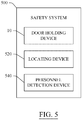
- the door holding device 10 may be part of a wireless communication safety system 500 that includes the innovative door holding device 10, a locating device 520, and a personnel detection device 540.
- the locating device 520 enables the user to locate the door holding device 10 within a building structure (e.g., the locating device 520 enables a firefighter fighting a fire in a zero visibility or near zero visibility smoke-filled building to be able to more easily find the building exit door to which the door holding device 10 is attached so that he or she may safely exit the building).
- the locating device 520 may include (i) a light emitting device for emitting a visual signal from the door holding device 10, and/or (ii) an audio device for emitting an audible signal from the door holding device 10.
- a light emitting device for emitting a visual signal from the door holding device 10
- an audio device for emitting an audible signal from the door holding device 10.
- the locating device 520 when the locating device 520 is in the form of a light emitting device, it may comprise one or more flashing light emitting diode (LED) lights that visually direct a person to the door 54.
- LED flashing light emitting diode
- the locating device 520 when the locating device 520 is in the form of an audio device, it may comprise one or more alarms or sirens that audibly direct a person to the door 54.
- the personnel detection device 540 is configured to detect the presence and/or location of emergency response personnel (e.g., one or more firefighters) inside and/or outside a building in which the door holding device 10 is disposed.
- the emergency response personnel detection system 540 may comprise one or more radio frequency identification readers or transmitters and/or one or more radio frequency identification tags.
- Each radio frequency identification tag may be attached to a respective person (e.g., a firefighter) and/or object (e.g., additional door holding devices or markers inside and/or outside the structure) disposed inside the building structure so that a presence and/or location of the person (e.g., a firefighter) is capable of being determined by the emergency response personnel detection system.
- the one or more components 540 of the emergency response personnel detection system that are disposed on the door holding device 10 may comprise the one or more radio frequency identification readers or transmitters of the system.
- the personal detection device 540 can be configured to determine how long a firefighter has been inside the building and/or how long the firefighter had been inside if they are no longer inside the building and/or how long since they left the building.
- the personnel detection device 540 can detect and or transmit data of a firefighter's bodily functions, for example, vital signs, such as but not limited to blood pressure, heart rate, respiratory rate, body temperature, etc.). Still further, the personnel detection device 540 can detect and/or transmit data on environmental conditions within a structure (e.g., temperature, relative temperature, temperature fluctuations, smoke composition, smoke density, ambient air gas composition (e.g., carbon monoxide, oxygen, natural gas, etc.), measurement of the ambient air gases, etc.).
- a structure e.g., temperature, relative temperature, temperature fluctuations, smoke composition, smoke density, ambient air gas composition (e.g., carbon monoxide, oxygen, natural gas, etc.), measurement of the ambient air gases, etc.).
- the body assembly 20 of the door holding device 10 may be formed from a suitable plastic or metallic material, which is capable of being elastically deformed.
- the plastic or metallic material, which is used for forming the body assembly 20 of the door holding device 10 is sufficiently strong to withstand the forces exerted on the door 54 by the fire hose 58 being dragged through the opening 60 between the door frame 56 and the door 54 (see FIG. 4 ). That is, the door holding device 10 maintains the door 54 in the predetermined position as the fire hose 58 is dragged through the door opening 60 by the firefighting personnel.
- the door holding device 10 controls and limits the amount of air moving into a building structure by temporarily, or permanently holding a door in a mostly closed or other desired position during firefighting or other commercial or domestic operations and tasks.
- the door holding device 10 is capable of being deployed by a single firefighter or other person from either side of the door, thereby holding the door in place in a mostly closed position, while allowing fire hoses and firefighting personnel and equipment, or other persons or equipment, to pass through the threshold of the door.
- the quick-release mechanism 12 of the door holding device 10 described above allows a firefighter, or other person, to remove the device 10 with a gloved or ungloved hand in zero or clear visibility during an emergency egress situation or other situation.
- the door holding device 10 described above is an important life-saving tool for firefighters and other emergency response personnel.
- the door holding device 10 is capable of safely and reliably controlling both exterior and interior doors, inward and outward swinging commercial and residential doors, without disrupting their desired working objective.
- the door holding device 10 described herein is capable of securely fixing a door in place, while resisting forces that commonly occur during firefighting operations, such as those forces created by the advancing of the fire hose.
- the door holding device 10 described herein allows a firefighting crew to restrict the amount a door will be able to swing open, and the device fixes the door in a predetermined position so that fire hose line may be advanced into the building structure to extinguish a fire.
- the door holding device 10 incorporates a "quick release" feature to allow firefighting personnel to rapidly open the door and exit the structure with a minimal amount of manipulation.
- the door holding device 10 effectively restricts the amount of airflow through a door opening of the building structure and therefore, controls flow path while aiding in the restriction of fire growth.
- the door holding device 10 helps to keep fire growth in a reduced state, thereby allowing for a safer working environment for firefighters, and more time for victim rescue and conservation of civilian property.
- the door holding device 10 described herein may be deployed by a single member of the first firefighting crew to enter a building. Once deployed, it will fix a door in any desired position and will open only enough to allow for the entry of firefighters and fire hose lines to be advanced into the building. This will restrict the amount of air inflow, and therefore control the flow path, while aiding in restricting fire growth.
- the first and second clamp devices 22, 38 of the door holding device 10 are capable of being easily engaged and disengaged with the door 54 and door frame 56 so that the door holding device 10 can be positioned where needed.
- the door holding device 10 is reusable for multiple door holding installations, but also may be used for a single use installation (e.g., if the device 10 is damaged in a building fire).
- the door holding device 10 may be joined with other tools, equipment, and personal protective gear (i.e., firefighting equipment and gear), and may be carried on, and deployed by a single person (i.e., a single firefighter).
- the quick-release handle mechanism 12 of the door holding device 10 is easily releasable by a single hand of a person (i.e., one hand of a firefighter).
- the door holding device 10 is readily adaptable to virtually any door assembly, and is capable of withstanding the extreme temperatures and conditions of the firefighting environment (e.g., if the door holding device 10 is constructed of a durable metallic material).
- the door holding device 10 is able to be placed into use from either side of a door, while the user of the device 10 is either inside or outside of the building structure.
- the door holding device 10 is capable of withstanding forces acting on the device 10 while it is in use (e.g., those forces generated by the movement of the fire hose by the firefighting personnel).
- the door holding device 10 allows the door to withstand forces applied thereto while the device 10 is holding the door in place (e.g., those forces acting on the door as a result of the movement of the fire hose by the firefighting personnel).
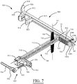
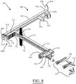
- FIGS. 6-30 illustrate another example embodiment of a door holding device 600 in accordance with an aspect of the innovation.
- the door holding device 600 includes a first arm assembly 700, a second arm assembly 800, a movable clamping mechanism 900, and a pivot device 1000 that pivotally connects the first and second arm assemblies 700, 800.
- the door holding device 600 illustrated in FIGS. 6-30 is configured to attach to a structure 650.
- the door holding device 600 attaches to a door 652 and a door frame 654 to securely hold the door 652 in a partially open (or closed) position to allow fire equipment (e.g., fire hoses) 656 through an opening or gap 658 in the partially open door structure 650.
- fire equipment e.g., fire hoses
- the structure 650 can be any type of structure, such as but not limited to a residential dwelling, a commercial or industrial building, schools, churches, etc.
- the door holding device 600 can be used on an inward or out swinging door.
- the innovative door holding device allows firefighters to view smoke emitting from the doorway where the door holding device is applied, which allows the firefighters to observe changes in fire conditions throughout the emergency. Observation of changes in fire conditions is a very large variable in tactical decision making.
- more than one door holding device 600 can be used within a structure to limit and control the air flow into and/or within the building. For example, if one door holding device 600 is on the front door of a structure and another is on a door in a common hallway within the structure, the amount of air flow into and within the structure can be effectively controlled.
- the first arm assembly 700 is adjustable and is configured to attach to a structure, such as but not limited to the door frame 654 as will be described further below.
- the first arm assembly 700 includes an L-shaped arm 710 and a support structure 750.
- the L-shaped arm 710 includes a first longitudinal part 712 having a proximate (first) end 714 and a distal (second) end 716, and a stationary part 718 having a proximate (first) end 720 and a distal (second) end 722.
- a channel 724 is defined along a first longitudinal axis A1 on each side of the longitudinal part 712 such that the longitudinal part has an I-beam shaped cross-section.
- the longitudinal part 712 further includes a track 726 having recesses 728 is defined on one or both sides therein that facilitates the movement of the movable clamping mechanism 900 along the longitudinal part 712 as will be described further below.
- the stationary part 718 has a second longitudinal axis A2 and extends from the distal end 716 of the longitudinal part 712 such that the first and second longitudinal axes A1, A2 are substantially perpendicular to each other.
- the stationary part 718 includes a stationary pad 730 (e.g., rubber pad) disposed on a face 731 thereon that includes teeth 732.
- the teeth 732 may be made from a rigid material, such as but not limited to metal, that are configured to bite into or grip the structure (e.g., door frame) when the pad 730 is compressed as will be described further below.
- the teeth 732 may be an integrated part of the stationary part 718 and thus, integrated directly on the face 731 of the stationary part 718.
- the support structure 750 includes a pair of fins 752 that extend along a third longitudinal axis A3 from each side of the longitudinal part 712 such that the first, second, and third longitudinal axes A1, A2, A3 are all substantially perpendicular to each other, see FIG. 7 .
- a pad (e.g., rubber pad) 754 having teeth (e.g., metal teeth) 756 are attached to a contacting face or surface 758 of each fin 752 such that the teeth 756 bite into or grip the structure (e.g., door frame) to stabilize the door holding device 600 in a vertical direction.
- the teeth 756 may be an integrated part of each fin 752.
- the fins 752 have a tapered rectangular shape, but it is to be understood that the fins 752 can have any geometric shape, such as but not limited to square, triangular, circular, etc.
- the support structure 750 may include attachable/detachable stabilizers or wedges 760 that fit onto the support structure 750 for additional stability.
- the wedges 760 can be used to hold the door 652 in a desired position when a U-shaped holder 816 (described below) is disengaged from the door 652 and the second arm assembly 800 is out of the way, as shown in FIG 22A . Still further, firefighters can use the wedges 760 individually or collectively to make up for a gap created in a the-shaped holder 816 when the thickness of a vertical end 660 of the door 652 is less than a width of U-shaped holder 816. Still even further, the wedges 760 can be used in conjunction with the movable clamping mechanism 900 to fill a gap if the door frame 654 is smaller than anticipated.
- the second arm assembly 800 includes a second longitudinal part 810 having a proximate (first) end 812 and a distal (second) end 814, a U-shaped holder 816 disposed at the proximate end 812, and a release device 818 also disposed at the proximate end 812.
- the U-shaped holder 816 is configured to receive a vertical end 660 of the door 652 to secure the door 652 in the partially open (or closed) position as shown in FIG. 15 .
- the U-shaped holder 816 may be made from a rigid (e.g., metal), a resilient (e.g., rubber), or a spring like material that facilitates the quick and easy engagement and disengagement of the second arm assembly 800 from the door 652 while at the same time providing a high amount of friction to maintain the door 652 in the partially open position due to the hose 656 contacting the door.
- the U-shaped holder 816 attaches to an extended part 820 integrally attached to the proximate end 812 of the longitudinal part 810 via a bracket 822 and fasteners, as shown in FIG. 15 .
- the U-shaped holder 816 may be slidable along the longitudinal part 810 of the second arm assembly 800, as illustrated by the double sided arrow. This allows the opening 658 of the door 652 to be adjusted to different sized openings or gaps 658 (e.g., 18", 16", 14", 12", etc.).
- the U-shaped holder 816 can be adjustable via any mechanical means, such as but not limited to apertures defined in the longitudinal part 810 that receive a projection from the U-shaped part 816, friction fit, clips, etc.
- the U-shaped holder 816 may pivot like a hinge that would further facilitate adjustability of the opening 658.
- the release device 818 is disposed on an end face 824 at the proximate end 812 of the second longitudinal part 810 and includes a pair of fins 826 that extends substantially perpendicular to the second longitudinal part 810.
- the fins 826 have a tapered rectangular shape, but it is to be understood that the fins 826 can have any geometric shape, such as but not limited to square, triangular, circular, etc.
- the release device 818 is configured to allow the users to hand strike the release device 818 to disengage the second arm assembly 800 from the door 652.
- the movable clamping mechanism 900 is configured to clamp the door holding mechanism to the structure 650.
- the primary entry door to the structure is closed and sometimes locked.
- a set of iron tools are used to force entry.
- the door frame 654 can be severely damaged and may crack and/or splinter if the door frame is wood. Due to this disfiguration, a strong clamping force is required to crush the splintered pieces back into place so that the door holding device can be adequately applied to the door frame.
- one side 664 of the door frame 654 is splintered and the movable clamping mechanism 900 provides enough force to force the splintered door frame back into place.
- the movable clamping mechanism 900 travels along the first longitudinal axis A1 of the longitudinal part 712 and includes a traveler 910 and clamp tightening device 930.
- the traveler 910 engages one or more sides of the longitudinal part 712 and is configured to slide along the longitudinal part 712.
- the traveler 910 includes a quick release lever 912 that facilitates quick movement of the traveler 910 along the longitudinal part 712.
- the quick release lever 912 engages the recesses 728 defined on one side of the track 726 to hold the traveler 910 (and accordingly, the movable clamping mechanism 900) in position when the door holding device 600 is attached to the structure 650.
- the user presses the quick release lever 912 to disengage the quick release lever 912 from the recesses 728 defined in the track 726 and slides the movable clamping mechanism 900 along the longitudinal part 712.
- the user simply releases the quick release lever 912 and a spring 913 biases the quick release lever 912 back into one of the recesses 728.
- the traveler 910 further includes an extension part 914 that extends from the longitudinal part 712 substantially parallel to the stationary part 718.
- the extension part 914 and the stationary part 718 form an adjustable U-shaped clamp.
- a threaded aperture 916 is defined in the extension part 914 that facilitates the tightening of the door holding device 600 against the door frame 654 as will be described below.
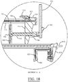
- the clamp tightening device 930 includes a threaded rod 932 threadedly disposed in the threaded aperture 916 and a handle (or knob) 934 having a switching lever 936 to switch the clamp tightening device 930 between a tightening state and a release state, and a movable pad 950.
- the threaded rod 932 threads through the threaded aperture 916 and attaches to a rear of the movable pad 950.
- the clamp tightening device 930 via movement of the handle 934, tightens the movable pad 950 against the door frame 654.
- the movable pad 950 compresses against the door frame 654, which in turn forces the stationary part 718 to compress against an opposite side of the door frame 654 to secure the door holding device 600 to the door frame 654.
- the user simply switches the switching lever 936 to the release position and ratchets the clamp tightening device 930 via the handle 934 to loosen the movable pad 950 from the door frame 654.
- the handle 934 can include indicators (e.g., markings, color indicators, etc.) to allow firefighters to quickly recognize if the clamp tightening device 930 is in a ready position and set up to tighten to or removed from the door frame 654.
- the indicators can save time, which is critical in an emergency situation.
- the movable pad (e.g., rubber pad) 950 includes teeth 952.
- the teeth 952 may be made from a rigid material, such as but not limited to metal, that are configured to bite into or grip the door frame 654 when the movable pad 950 is compressed against the door frame 654.
- the pivot device 1000 is configured to allow the first and second arm assemblies 700, 800 to pivot with respect to each other.
- the pivot device 1000 allows the first arm assembly 700 if the door holding device 600 to remain attached to the door frame 654 while allowing the second arm assembly 800 to pivot out of the way (e.g., against a wall 668 of the structure 650). This allows the firefighters to move freely through the door opening 658 without the risk of having their clothes and other equipment inadvertently get caught on the door holding device 600.
- the pivot device includes a first hinge 1002 having a first aperture 1004 defined therein and integrally attached to the distal end 722 of the stationary part 718 and a second hinge 1006 having a second aperture 1008 defined therein and integrally attached to the distal end 814 of the second longitudinal part 810.
- the pivot device 1000 further includes a band 1010 and a face (surface) 1012 having a first and second band apertures 1014, 1016 defined therein.
- the first and second hinges 1002, 1004 are connected to each other with the band 1010 and fasteners 1018 extend through the first and second apertures 1004, 1008 and through the respective first and second band aperture 1014, 1016.
- the pivot device 1000 allows the first and second arm assemblies 700, 800 to pivot with respect to each other, as illustrated by the double sided arrows in FIG. 22 . Both the first and second hinges 1002, 1004 are independent of each other thus, the first arm assembly 700 can pivot independently of the second arm assembly 800 and vice versa.
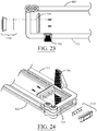
- the door holding device may further include an electronic wireless communicator (e.g., transmitter and/or receiver) 1100 that can communicate with an external electronic system to be used as described above, a locating device 520, a personnel detection device 540, a visual and/or audio warning device, etc.
- the wireless communicator 1100 may be located in the stationary part 718 of the first arm assembly 700. It is to be understood, however, that the wireless communicator may be located in another portion of the door holding device 600 such as in the second arm assembly 800.
- the wireless communicator 1100 can detect and/or transmit data of a firefighter's bodily functions or vital signs, such as but not limited to blood pressure, heart rate, respiratory rate, body temperature, etc.).
- the wireless communicator 1100 can detect and/or transmit data on environmental conditions within a building (e.g., temperature, relative temperature, temperature fluctuations, smoke composition, smoke density, ambient air gas composition (e.g., carbon monoxide, oxygen, natural gas, etc.), measurement of the ambient air gases, etc.
- environmental conditions within a building e.g., temperature, relative temperature, temperature fluctuations, smoke composition, smoke density, ambient air gas composition (e.g., carbon monoxide, oxygen, natural gas, etc.), measurement of the ambient air gases, etc.
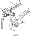
- the door holding device may further include a clamping device 1200 that holds the first and second arm assemblies 700, 800 in a transport/storage position (see FIGS. 6 and 10 ).
- the clamping device may be comprised of a hook, snap, clip, magnet, etc. that holds the first and second arm assemblies 700, 800 together.
- the clamping device 1200 may be a magnet and may be disposed on the extension part 914. Thus, the magnet contacts the second arm assembly 800 to secure it to the first arm assembly 700.
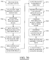
- the door holding device 600 is provided that includes the first arm assembly 700, the second arm assembly 800, and a movable clamping mechanism 900.
- the first arm assembly 700 is placed against the door frame 654 such that the longitudinal part 712 and the support structure 750 contact an end face 662 of the door frame 654 and the stationary part 810 contacts one (first) side 664 of the door frame 654.
- the release lever 912 is actuated so that the release lever is disengaged from the recesses 728 in the track 726.
- the movable clamping mechanism 900 is move (slid) along the track 726 until at 2910, the movable pad 950 contacts an opposite (second) side 666 of the door frame 654.
- the release lever 912 is released and reengages the recesses 728 on the track 726.
- the handle 934 is activated in the tightening direction.
- the movable pad 950 is tightened against the opposite side 666 of the door frame 654.
- the movable pad 950 is compressed against the opposite side 666 of the door frame 654.
- the stationary pad 730 is compressed against the one side 664 of the door frame 654.
- the second arm assembly 800 is pivoted toward the vertical end 660 of the door 652.
- the vertical end 660 of the door 652 is placed into the U-shaped holder 816.
Landscapes
- Engineering & Computer Science (AREA)
- Mechanical Engineering (AREA)
- Special Wing (AREA)
Description
- /
- The invention generally relates to a door holding device. More particularly, the invention relates to a door holding device that is configured to fix a door of a building structure in a predetermined position while firefighting operations are taking place in the building structure.
- Studies conducted by Underwriters Laboratories (UL), National Institute of Standards and Technology (NIST), and The Bureau of Alcohol, Tobacco, Firearms and Explosives (ATF) Fire Research Laboratory have concluded that ventilation flow paths within a structure fire are directly attributed to the spread of fire, and the loss of lives and property. The above studies proved that controlling the amount of opening of the door (i.e. door control) used by firefighters is the valve for limiting flow path. Flow path is the volume between an inlet and an outlet that allows the movement of heat and smoke from higher pressure within the fire area toward the lower pressure areas accessible via door and window openings. Firefighting operations conducted in the flow path, between the fire and where the fire wants to go, will place civilians and firefighters at significant risk due to the increase flow of fire, heat and smoke toward their position. Fire, heat and smoke also can cause structural members to fail or windows to shatter causing rapid changes in flow path within a structure. These rapid changes may necessitate the emergent evacuation of firefighting personnel.
- Door control has been identified as the most important component in restricting the flow of air into a building that is on fire. Lack of flow path control, by either intentional or unintentional ventilation of a building on fire has been proven to accelerate progression of the fire. This resulting rapid fire progression has resulted in civilian and firefighter injuries and deaths. Most fire departments do not have enough manpower on a scene to allow dedication of a member to stay at the entry door keeping it closed as much as possible while crews operate inside the building with a fire hose line.
- The conventional means for controlling exterior and interior doors is a wooden or plastic triangular wedge. These tools have been used in the fire service for decades, but offer little to no assurance that they will fix a door in place while resisting force from all directions that occur during firefighting operations, such as advancing a fire hose line into and throughout the structure. Most importantly, the conventional wedge in no way offers a means for efficient and rapid removal thereof during emergency egress by firefighters.
- The following presents a simplified summary in order to provide a basic understanding of some aspects of the innovation. This summary is not an extensive overview of the innovation. It is not intended to identify key/critical elements or to delineate the scope of the innovation. Its sole purpose is to present some concepts of the innovation in a simplified form as a prelude to the more detailed description that is presented later.
- In an aspect of the innovation a door holding device is disclosed that includes a first arm assembly, a second arm assembly, a pivot device that pivotally connects the first arm assembly to the second arm assembly, and a movable clamping mechanism slidably attached to the second arm assembly that clamps to a structure to secure the door holding device to the structure.
- A door holding device according to the preamble of
claim 1 is disclosed in documentDE 203 04 592 U1 . - In another aspect of the innovation a method of securing a door in a partially open configuration is disclosed that includes providing a door holding device having a first arm assembly, a second arm assembly, and a movable clamping mechanism, placing the first arm assembly against a door frame whereby a longitudinal part contacts an end face of the door frame and a stationary part contacts one side of the door frame, moving the movable clamping mechanism along the longitudinal part toward the door frame, contacting an opposite side of the door frame with a movable pad on the movable clamping mechanism, tightening the movable pad against the opposite side of the door frame, compressing the movable pad against the opposite side of the door frame, compressing a stationary pad against the one side of the door frame, and placing a vertical end of the door into the a U-shaped holder.
- The following description and drawings set forth certain illustrative aspects and implementations. These are indicative of but a few of the various ways in which one or more aspects may be employed. Other aspects, advantages, or novel features of the disclosure will become apparent from the following detailed description when considered in conjunction with the drawings.
- The accompanying drawings, which are incorporated in and constitute a part of the specification, illustrate various systems, methods, and other embodiments of the disclosure. Illustrated element boundaries (e.g., boxes, groups of boxes, or other shapes) in the figures represent one example of the boundaries. In some examples one element may be designed as multiple elements or multiple elements may be designed as one element. In some examples, an element shown as an internal component of another element may be implemented as an external component and vice versa.
-
FIGS. 1 and2 are perspective views of one example of a door holding device , not in accordance with the invention. -
FIG. 3 is a top plan view of the door holding device ofFIG. 1 . -
FIG. 4 is a perspective view illustrating the door holding device ofFIG. 1 being used to hold a door in a mostly closed position. -
FIG. 5 is a block diagram illustration of a safety system that incorporates the innovative door holding device in accordance with an aspect of the innovation. -
FIG. 6 is a perspective view of another example embodiment of a door holding device in accordance with an aspect of the innovation. -
FIG. 6A is a view of a door structure incorporating the innovative door holding device in accordance with an aspect of the innovation. -
FIGS. 7 and8 are opposite end perspective views of the innovative door holding device ofFIG. 6 in accordance with an aspect of the innovation. -
FIG. 9 is an exploded view of the innovative door holding device ofFIG. 6 in accordance with an aspect of the innovation. -
FIG. 10 is a side view of the innovative door holding device ofFIG. 6 in accordance with an aspect of the innovation. -
FIG. 11 is a top view of the innovative door holding device ofFIG. 6 in accordance with an aspect of the innovation. -
FIG. 12 is a bottom view of the innovative door holding device ofFIG. 6 in accordance with an aspect of the innovation. -
FIGS. 13 and 14 are opposite end end views of the innovative door holding device ofFIG. 6 in accordance with an aspect of the innovation. -
FIG. 15 is a close up view of a U-shaped holding device securing a door in accordance with an aspect of the innovation. -
FIG. 16 is a close-up view illustrating an adjustable feature of the U-shaped holder in accordance with an aspect of the innovation. -
FIGS. 17 and18 are close-up views of a movable clamping mechanism in a non-actuated state and an actuated state respectively in accordance with an aspect of the innovation. -
FIG. 19 is a close-up view of a handle of the movable clamping mechanism in accordance with an aspect of the innovation. -
FIGS. 20 and21 are views of the door structure illustrating the clamping process of the movable clamping mechanism in accordance with an aspect of the innovation. -
FIG. 22 is a close-up view of a pivot device in accordance with an aspect of the innovation. -
FIG. 22A is a view of the door holding device attached to the door structure but not attached to the door in accordance with an aspect of the innovation. -
FIGS. 23 and 24 are close-up views of a wireless communicator in accordance with an aspect of the innovation. -
FIG. 25 is a close-up view of a clamping device in accordance with an aspect of the innovation. -
FIGS. 26-28 are perspective, plan, and top views of the door structure incorporating the innovative door holding device in accordance with an aspect of the innovation. -
FIG. 29 is a close-up view illustrating a pivoting feature of the U-shaped holder in accordance with an aspect of the innovation. -
FIG. 30 is a block diagram illustration of a method of attaching the innovative door holding device to a door frame structure in accordance with an aspect of the innovation. - The innovation is now described with reference to the drawings, wherein like reference numerals are used to refer to like elements throughout. In the following description, for purposes of explanation, numerous specific details are set forth in order to provide a thorough understanding of the subject innovation. It may be evident, however, that the innovation can be practiced without these specific details. In other instances, well-known structures and devices are shown in block diagram form in order to facilitate describing the innovation.
- While specific characteristics are described herein (e.g., thickness, orientation, configuration, etc.), it is to be understood that the features, functions and benefits of the innovation can employ characteristics that vary from those described herein. These alternatives are to be included within the scope of the innovation as defined in the claims appended hereto.
- While, for purposes of simplicity of explanation, the one or more methodologies shown herein, e.g., in the form of a flow chart, are shown and described as a series of acts, it is to be understood and appreciated that the subject innovation is not limited by the order of acts, as some acts may, in accordance with the innovation, occur in a different order and/or concurrently with other acts from that shown and described herein. For example, those skilled in the art will understand and appreciate that a methodology could alternatively be represented as a series of interrelated states or events, such as in a state diagram. Moreover, not all illustrated acts may be required to implement a methodology in accordance with the innovation.
- Disclosed herein is an innovative door holding device that overcomes the aforementioned disadvantages. Studies performed at UL found that while fighting a fire, allowing a door to remain partially open approximately 18 inches is an optimal gap or opening in order to allow the movement of fire hoses into the structure while simultaneously controlling the flow path defined above. The innovative door holding device disclosed herein is capable of securely fixing a door in place, while resisting forces that commonly occur during firefighting operations, such as those forces created by the advancing of the fire hose. Furthermore, the innovative door holding device effectively restricts the amount of airflow through a door opening, and therefore controls flow path, while aiding in the restriction of fire growth.
- In addition, the innovative door holding device allows firefighters to view smoke emitting from the doorway where the door holding device is applied, which allows the firefighters to observe changes in fire conditions throughout the emergency. Observation of changes in fire conditions is a very large variable in tactical decision making.
- The innovative door holding device, however, includes adjustable features that allows firefighters to adjust the door opening greater or less than 18 inches or where in instances where the fire is mostly extinguished. In these instances, firefighters are investigating void spaces in the structure where fire can hide and ultimately cause the fire to begin again if left undetected. Because the flow path of air into the structure can reach these void spaces and there may be no need to advance the fire hose further, firefighters may want to adjust the door opening in an even more closed position to restrict the movement of air that much more in order to protect themselves and the structure.
- Referring now to the drawings,
FIGS. 1 and2 are perspective views of an innovativedoor holding device 10,FIG. 3 is a top view of the innovativedoor holding device 10, andFIG. 4 is an illustration of a door structure that includes adoor 54, adoor frame 56, and adoor opening 60 in accordance with an aspect of the innovation. The innovativedoor holding device 10 holds thedoor 54 in a partially open (or partially closed) position when firefighters are in the process of any or all firefighting procedures. In other words, thedoor holding device 10 secures thedoor 54 in a position that is open enough to allow firefighters to run fire hoses through agap 62 in thedoor opening 60, but closed enough to restrict the flow of air/ventilation through thedoor opening 60. - The
door holding device 10 includes abody assembly 20 and a handle (quick-release)mechanism 12 that connects to thebody portion 20. As will be described further below, thehandle mechanism 12 facilitates a quick disengagement of thedoor holding device 10 from the door structure. - The
body assembly 20 includes afirst clamp device 22, asecond clamp device 38, and a pivoting mechanism 36 (e.g., a hinge) pivotally connecting thefirst clamp device 22 and thesecond clamp device 38 to each other. Thefirst clamp device 22 is configured to attach to a structure (e.g., door, door frame, etc.) and includes afirst arm 23 and a first clamp comprising afirst clamp member 24 and asecond clamp member 30. Thefirst arm 23 includes a proximate end 23A having afirst pivot portion 36A attached thereto, and adistal end 23B. The first andsecond clamp members distal end 23B of thefirst arm 23 to thereby form a general U-shape with thedistal end 23B of thefirst arm 23. Thus, the first andsecond clamp members space 23C defined between the first andsecond clamp members door holding device 10 is in use. - The
first clamp member 24 includes a firstclamp pad portion 28 disposed on an inside surface thereof and thesecond clamp member 30 includes a secondclamp pad portion 34 disposed on an inside surface thereof. When thedoor holding device 10 is in use, the firstclamp pad portion 28 is disposed against a surface (first surface) of the structure and the secondclamp pad portion 34 is disposed against a generally opposite (second) surface of the structure. In one or more embodiments, theclamp pad portions second clamp members first clamp device 22 and the opposed surfaces of the structure. Forming theclamp pad portions clamp members first clamp device 22. - The
first clamp member 24 further includes afirst flange 26 that extends from adistal end 24A of thefirst clamp member 24 in a direction away from thesecond clamp member 30. Similarly, thesecond clamp member 30 further includes asecond flange 32 that extends from adistal end 30A of thesecond clamp member 30 in a direction away from thefirst clamp member 24. The first andsecond flanges first clamp device 22 from the structure by a user. More specifically, when the user grasps and pulls on either the first or second flange, itsrespective clamp member first clamp device 22 is disengaged from the structure. Thus, the first andsecond flanges first clamp device 22 from the structure. In addition, thefirst flange 26 of thefirst clamp member 24 also provides a connection between thehandle mechanism 12 and thebody assembly 20. Specifically, thefirst flange 26 includes aproximate end 26A that connects to thedistal end 24A of thefirst clamp member 24 and adistal end 26B that connects to thehandle mechanism 12 described further below. - The
body assembly 20 of thedoor holding device 10 may be formed from a resilient material (e.g., a resilient plastic or metal) so that the first and second spaced-apartclamp members first clamp device 22 are capable of being resiliently deformed when they are engaged with the structure. As such, thefirst clamp device 22 of thedoor holding device 10 is capable of securely grasping the portion of the structure when its prong-like clamp members clamp members first arm 23 may be formed from a rigid material and the first andsecond clamp members - The
second clamp device 38 is configured to attach to a structure (e.g., door, door frame, etc.) and includes asecond arm 39 and a second clamp comprising athird clamp member 40 and afourth clamp member 46. Thesecond arm 39 includes aproximate end 39A having asecond pivot portion 36B attached thereto, and adistal end 39B. The third andfourth clamp members distal end 39B of thesecond arm 39 to thereby form a general U-shape with thedistal end 39B of thesecond arm 39. Thus, the third andfourth clamp members space 39C defined between the third andfourth clamp members door holding device 10 is in use. - The
third clamp member 40 includes a thirdclamp pad portion 44 disposed on an inside surface thereof and thefourth clamp member 46 includes a fourthclamp pad portion 48 disposed on an inside surface thereof. When thedoor holding device 10 is in use, the thirdclamp pad portion 44 is disposed against a surface (first surface) of the structure and the fourthclamp pad portion 48 is disposed against a generally opposite (second) surface of the structure. In one or more embodiments, theclamp pad portions fourth clamp members second clamp device 38 and the opposed surfaces of the structure. Forming theclamp pad portions clamp members second clamp device 38. - The
third clamp member 40 further includes athird flange 42 that extends from adistal end 40A of thethird clamp member 40 in a direction away from thefourth clamp member 46. Thethird flange 42 facilitates a disengagement of thesecond clamp device 38 from the structure by the user. More specifically, when the user grasps and pulls on thethird flange 42, thethird clamp member 40 is deformed outwardly away from the surface of the structure, and thesecond clamp device 38 is disengaged from the structure. Thus, thethird flange 42 functions as a release mechanism so as to allow the user to easily disengage thesecond clamp device 38 from the structure. - As described above the
body assembly 20 of thedoor holding device 10 may be formed from a resilient material (e.g., a resilient plastic or metal) so that the third and fourth spaced-apartclamp members second clamp device 22 are capable of being resiliently deformed when they are engaged with the structure. As such, thesecond clamp device 38 of thedoor holding device 10 is capable of securely grasping the portion of the structure when its prong-like clamp members fourth clamp members second arm 39 may be formed from a rigid material and the third andfourth clamp members - Still referring to
FIGS. 1-3 , thepivoting mechanism 36 provides a pivoting connection between thefirst clamp device 22 and thesecond clamp device 38 to enable thedoor holding device 10 to be adjusted for different door configurations. In the example embodiment described herein and illustrated in the figures, thepivoting mechanism 36 is comprised of thefirst pivot portion 36A and thesecond pivot portion 36B mentioned above, and arod 36C (e.g., hinge pin). It is to be understood, however, that thepivoting mechanism 36 can be any type of pivoting mechanism that allows thefirst pivot portion 36A and thesecond pivot portion 36B pivot with respect to each other, such as but not limited to, a ball and socket type device, a fulcrum type device, etc. - As mentioned above, the
first pivot portion 36A is disposed at a proximate end 23A of thefirst arm 23. In the example embodiment disclosed herein, thefirst pivot portion 36A has a circular shape and essentially makes up half of thepivot mechanism 36. Similarly, thesecond pivot portion 36B is disposed at aproximate end 39A of thesecond arm 39. In the example embodiment disclosed herein, thesecond pivot portion 36B has a circular shape and essentially makes up the other half of thepivot mechanism 36. Thefirst pivot portion 36A and thesecond pivot portion 36B are offset from each other such that when they are joined, they form a hinge having an elongated aperture defined therein. Therod 36C is then inserted through the elongated aperture formed by the joining of the first andsecond pivot portions first clamp device 22 with thesecond clamp device 38. - In one or more embodiments, the
pivot mechanism 36 allows theopening gap 60 between thedoor 54 and thedoor frame 56 to be adjusted by a user so that thedoor holding device 10 may be readily adapted to different applications (i.e., thepivot mechanism 36 allows thedoor holding device 10 to be easily adjustable so as to accommodate objects of varying size passing through the door opening gap 60). In addition, in one or more embodiments, thepivot mechanism 36 enables a person disposed on the side of thedoor holding device 10, which is opposite to the quick-release mechanism 12, to "punch out" thedevice 10 and "break" the pivot mechanism 36 (e.g., a firefighter trying to make a quick emergency exit from the building structure with fire and heat at his or her back). In these one or more embodiments, when thepivot mechanism 36 collapses, thedoor 54 is able to freely swing open because thedoor holding device 10 will no longer be holding thedoor 54 in the mostly closed position. In addition, thepivot mechanism 36 allows thedoor holding device 10 to be folded for easy transport, storage, and can be mated with other firefighting tools. - Referring to
FIGS. 1-3 , thehandle mechanism 12 is configured to be grasped by the user so as to allow the user to quickly and easily (quick release) disengage thedoor holding device 10 and permit a rapid opening of thedoor 54. Thehandle mechanism 12 includes an angled rod member with abent rod portion 14 that is connected to a generallystraight rod portion 18 by anelbow portion 16. In the illustrated embodiment, thebent rod portion 14 is oriented at an acute angle θ relative to the generally straight rod portion 18 (i.e., a longitudinal axis A1 of thebent rod portion 14 is disposed at an acute angle θ relative to a longitudinal axis A2 of the generally straight rod portion 18). Advantageously, the elongate geometry and the large size of the angled rod member makes the quick-release mechanism 12 easier for a user to find in an environment with little visibility (i.e., in a smoke-filled building that is being traversed by a firefighting crew). - Referring to
FIG. 5 , in an alternate embodiment, thedoor holding device 10 may be part of a wirelesscommunication safety system 500 that includes the innovativedoor holding device 10, a locatingdevice 520, and apersonnel detection device 540. The locatingdevice 520 enables the user to locate thedoor holding device 10 within a building structure (e.g., the locatingdevice 520 enables a firefighter fighting a fire in a zero visibility or near zero visibility smoke-filled building to be able to more easily find the building exit door to which thedoor holding device 10 is attached so that he or she may safely exit the building). In one or more embodiments, the locatingdevice 520 may include (i) a light emitting device for emitting a visual signal from thedoor holding device 10, and/or (ii) an audio device for emitting an audible signal from thedoor holding device 10. For example, when the locatingdevice 520 is in the form of a light emitting device, it may comprise one or more flashing light emitting diode (LED) lights that visually direct a person to thedoor 54. As another example, when the locatingdevice 520 is in the form of an audio device, it may comprise one or more alarms or sirens that audibly direct a person to thedoor 54. - The
personnel detection device 540 is configured to detect the presence and/or location of emergency response personnel (e.g., one or more firefighters) inside and/or outside a building in which thedoor holding device 10 is disposed. In one or more embodiments, the emergency responsepersonnel detection system 540 may comprise one or more radio frequency identification readers or transmitters and/or one or more radio frequency identification tags. Each radio frequency identification tag may be attached to a respective person (e.g., a firefighter) and/or object (e.g., additional door holding devices or markers inside and/or outside the structure) disposed inside the building structure so that a presence and/or location of the person (e.g., a firefighter) is capable of being determined by the emergency response personnel detection system. In these one or more embodiments, the one ormore components 540 of the emergency response personnel detection system that are disposed on thedoor holding device 10 may comprise the one or more radio frequency identification readers or transmitters of the system. In other embodiments, thepersonal detection device 540 can be configured to determine how long a firefighter has been inside the building and/or how long the firefighter had been inside if they are no longer inside the building and/or how long since they left the building. - In other embodiments, the
personnel detection device 540 can detect and or transmit data of a firefighter's bodily functions, for example, vital signs, such as but not limited to blood pressure, heart rate, respiratory rate, body temperature, etc.). Still further, thepersonnel detection device 540 can detect and/or transmit data on environmental conditions within a structure (e.g., temperature, relative temperature, temperature fluctuations, smoke composition, smoke density, ambient air gas composition (e.g., carbon monoxide, oxygen, natural gas, etc.), measurement of the ambient air gases, etc.). - As mentioned above, in the illustrative embodiment, the
body assembly 20 of thedoor holding device 10 may be formed from a suitable plastic or metallic material, which is capable of being elastically deformed. In the illustrative embodiment, the plastic or metallic material, which is used for forming thebody assembly 20 of thedoor holding device 10, is sufficiently strong to withstand the forces exerted on thedoor 54 by thefire hose 58 being dragged through theopening 60 between thedoor frame 56 and the door 54 (seeFIG. 4 ). That is, thedoor holding device 10 maintains thedoor 54 in the predetermined position as thefire hose 58 is dragged through the door opening 60 by the firefighting personnel. - Advantageously, the
door holding device 10 controls and limits the amount of air moving into a building structure by temporarily, or permanently holding a door in a mostly closed or other desired position during firefighting or other commercial or domestic operations and tasks. Thedoor holding device 10 is capable of being deployed by a single firefighter or other person from either side of the door, thereby holding the door in place in a mostly closed position, while allowing fire hoses and firefighting personnel and equipment, or other persons or equipment, to pass through the threshold of the door. The quick-release mechanism 12 of thedoor holding device 10 described above allows a firefighter, or other person, to remove thedevice 10 with a gloved or ungloved hand in zero or clear visibility during an emergency egress situation or other situation. Because of its operability and efficacy, thedoor holding device 10 described above is an important life-saving tool for firefighters and other emergency response personnel. Advantageously, thedoor holding device 10 is capable of safely and reliably controlling both exterior and interior doors, inward and outward swinging commercial and residential doors, without disrupting their desired working objective. - It is readily apparent that the door holding device offers numerous advantages. First, the
door holding device 10 described herein is capable of securely fixing a door in place, while resisting forces that commonly occur during firefighting operations, such as those forces created by the advancing of the fire hose. Advantageously, thedoor holding device 10 described herein allows a firefighting crew to restrict the amount a door will be able to swing open, and the device fixes the door in a predetermined position so that fire hose line may be advanced into the building structure to extinguish a fire. Second, thedoor holding device 10 incorporates a "quick release" feature to allow firefighting personnel to rapidly open the door and exit the structure with a minimal amount of manipulation. Finally, thedoor holding device 10 effectively restricts the amount of airflow through a door opening of the building structure and therefore, controls flow path while aiding in the restriction of fire growth. By controlling the flow path through the building, thedoor holding device 10 helps to keep fire growth in a reduced state, thereby allowing for a safer working environment for firefighters, and more time for victim rescue and conservation of civilian property. - In one or more embodiments, the
door holding device 10 described herein may be deployed by a single member of the first firefighting crew to enter a building. Once deployed, it will fix a door in any desired position and will open only enough to allow for the entry of firefighters and fire hose lines to be advanced into the building. This will restrict the amount of air inflow, and therefore control the flow path, while aiding in restricting fire growth. Advantageously, the first andsecond clamp devices door holding device 10 are capable of being easily engaged and disengaged with thedoor 54 anddoor frame 56 so that thedoor holding device 10 can be positioned where needed. - The
door holding device 10 is reusable for multiple door holding installations, but also may be used for a single use installation (e.g., if thedevice 10 is damaged in a building fire). In one or more embodiments, thedoor holding device 10 may be joined with other tools, equipment, and personal protective gear (i.e., firefighting equipment and gear), and may be carried on, and deployed by a single person (i.e., a single firefighter). The quick-release handle mechanism 12 of thedoor holding device 10 is easily releasable by a single hand of a person (i.e., one hand of a firefighter). Advantageously, thedoor holding device 10 is readily adaptable to virtually any door assembly, and is capable of withstanding the extreme temperatures and conditions of the firefighting environment (e.g., if thedoor holding device 10 is constructed of a durable metallic material). Thedoor holding device 10 is able to be placed into use from either side of a door, while the user of thedevice 10 is either inside or outside of the building structure. As explained above, thedoor holding device 10 is capable of withstanding forces acting on thedevice 10 while it is in use (e.g., those forces generated by the movement of the fire hose by the firefighting personnel). Also, thedoor holding device 10 allows the door to withstand forces applied thereto while thedevice 10 is holding the door in place (e.g., those forces acting on the door as a result of the movement of the fire hose by the firefighting personnel). -
FIGS. 6-30 illustrate another example embodiment of adoor holding device 600 in accordance with an aspect of the innovation. Referring toFIGS. 6 and6A , thedoor holding device 600 includes afirst arm assembly 700, asecond arm assembly 800, amovable clamping mechanism 900, and apivot device 1000 that pivotally connects the first andsecond arm assemblies door holding device 600 illustrated inFIGS. 6-30 is configured to attach to astructure 650. More specifically, thedoor holding device 600 attaches to adoor 652 and adoor frame 654 to securely hold thedoor 652 in a partially open (or closed) position to allow fire equipment (e.g., fire hoses) 656 through an opening orgap 658 in the partiallyopen door structure 650. - The
structure 650 can be any type of structure, such as but not limited to a residential dwelling, a commercial or industrial building, schools, churches, etc. In addition, thedoor holding device 600 can be used on an inward or out swinging door. Still further, the innovative door holding device allows firefighters to view smoke emitting from the doorway where the door holding device is applied, which allows the firefighters to observe changes in fire conditions throughout the emergency. Observation of changes in fire conditions is a very large variable in tactical decision making. Still further, more than onedoor holding device 600 can be used within a structure to limit and control the air flow into and/or within the building. For example, if onedoor holding device 600 is on the front door of a structure and another is on a door in a common hallway within the structure, the amount of air flow into and within the structure can be effectively controlled. - Referring to
FIGS. 7-14 , thefirst arm assembly 700 is adjustable and is configured to attach to a structure, such as but not limited to thedoor frame 654 as will be described further below. Thefirst arm assembly 700 includes an L-shapedarm 710 and asupport structure 750. The L-shapedarm 710 includes a firstlongitudinal part 712 having a proximate (first)end 714 and a distal (second)end 716, and astationary part 718 having a proximate (first)end 720 and a distal (second)end 722. Achannel 724 is defined along a first longitudinal axis A1 on each side of thelongitudinal part 712 such that the longitudinal part has an I-beam shaped cross-section. Thelongitudinal part 712 further includes atrack 726 havingrecesses 728 is defined on one or both sides therein that facilitates the movement of themovable clamping mechanism 900 along thelongitudinal part 712 as will be described further below. - The
stationary part 718 has a second longitudinal axis A2 and extends from thedistal end 716 of thelongitudinal part 712 such that the first and second longitudinal axes A1, A2 are substantially perpendicular to each other. Thestationary part 718 includes a stationary pad 730 (e.g., rubber pad) disposed on aface 731 thereon that includesteeth 732. Theteeth 732 may be made from a rigid material, such as but not limited to metal, that are configured to bite into or grip the structure (e.g., door frame) when thepad 730 is compressed as will be described further below. In another embodiment, theteeth 732 may be an integrated part of thestationary part 718 and thus, integrated directly on theface 731 of thestationary part 718. - The
support structure 750 includes a pair offins 752 that extend along a third longitudinal axis A3 from each side of thelongitudinal part 712 such that the first, second, and third longitudinal axes A1, A2, A3 are all substantially perpendicular to each other, seeFIG. 7 . A pad (e.g., rubber pad) 754 having teeth (e.g., metal teeth) 756 are attached to a contacting face orsurface 758 of eachfin 752 such that theteeth 756 bite into or grip the structure (e.g., door frame) to stabilize thedoor holding device 600 in a vertical direction. In another embodiment, theteeth 756 may be an integrated part of eachfin 752. In the example embodiment illustrated in the figures, thefins 752 have a tapered rectangular shape, but it is to be understood that thefins 752 can have any geometric shape, such as but not limited to square, triangular, circular, etc. In another embodiment, thesupport structure 750 may include attachable/detachable stabilizers orwedges 760 that fit onto thesupport structure 750 for additional stability. - In other embodiments, the
wedges 760 can be used to hold thedoor 652 in a desired position when a U-shaped holder 816 (described below) is disengaged from thedoor 652 and thesecond arm assembly 800 is out of the way, as shown inFIG 22A . Still further, firefighters can use thewedges 760 individually or collectively to make up for a gap created in a the-shapedholder 816 when the thickness of avertical end 660 of thedoor 652 is less than a width ofU-shaped holder 816. Still even further, thewedges 760 can be used in conjunction with themovable clamping mechanism 900 to fill a gap if thedoor frame 654 is smaller than anticipated. - Still referring to
FIGS. 7-14 , thesecond arm assembly 800 includes a secondlongitudinal part 810 having a proximate (first)end 812 and a distal (second)end 814, aU-shaped holder 816 disposed at theproximate end 812, and arelease device 818 also disposed at theproximate end 812. TheU-shaped holder 816 is configured to receive avertical end 660 of thedoor 652 to secure thedoor 652 in the partially open (or closed) position as shown inFIG. 15 . TheU-shaped holder 816 may be made from a rigid (e.g., metal), a resilient (e.g., rubber), or a spring like material that facilitates the quick and easy engagement and disengagement of thesecond arm assembly 800 from thedoor 652 while at the same time providing a high amount of friction to maintain thedoor 652 in the partially open position due to thehose 656 contacting the door. TheU-shaped holder 816 attaches to anextended part 820 integrally attached to theproximate end 812 of thelongitudinal part 810 via abracket 822 and fasteners, as shown inFIG. 15 . - In another embodiment illustrated in
FIG. 16 , theU-shaped holder 816 may be slidable along thelongitudinal part 810 of thesecond arm assembly 800, as illustrated by the double sided arrow. This allows theopening 658 of thedoor 652 to be adjusted to different sized openings or gaps 658 (e.g., 18", 16", 14", 12", etc.). TheU-shaped holder 816 can be adjustable via any mechanical means, such as but not limited to apertures defined in thelongitudinal part 810 that receive a projection from theU-shaped part 816, friction fit, clips, etc. In another embodiment shown inFIG. 29 , theU-shaped holder 816 may pivot like a hinge that would further facilitate adjustability of theopening 658. - Referring again to
FIGS. 7-14 , therelease device 818 is disposed on anend face 824 at theproximate end 812 of the secondlongitudinal part 810 and includes a pair offins 826 that extends substantially perpendicular to the secondlongitudinal part 810. In the example embodiment illustrated in the figures, thefins 826 have a tapered rectangular shape, but it is to be understood that thefins 826 can have any geometric shape, such as but not limited to square, triangular, circular, etc. Therelease device 818 is configured to allow the users to hand strike therelease device 818 to disengage thesecond arm assembly 800 from thedoor 652. - Referring to
FIGS. 7-14 and17-21 , themovable clamping mechanism 900 is configured to clamp the door holding mechanism to thestructure 650. In addition, when firefighters arrive to the scene of a fire, the primary entry door to the structure is closed and sometimes locked. When it is locked, a set of iron tools are used to force entry. When this is done, thedoor frame 654 can be severely damaged and may crack and/or splinter if the door frame is wood. Due to this disfiguration, a strong clamping force is required to crush the splintered pieces back into place so that the door holding device can be adequately applied to the door frame. As shown inFIG, 27 , oneside 664 of thedoor frame 654 is splintered and themovable clamping mechanism 900 provides enough force to force the splintered door frame back into place. - The
movable clamping mechanism 900 travels along the first longitudinal axis A1 of thelongitudinal part 712 and includes atraveler 910 andclamp tightening device 930. Thetraveler 910 engages one or more sides of thelongitudinal part 712 and is configured to slide along thelongitudinal part 712. Thetraveler 910 includes aquick release lever 912 that facilitates quick movement of thetraveler 910 along thelongitudinal part 712. Thequick release lever 912 engages therecesses 728 defined on one side of thetrack 726 to hold the traveler 910 (and accordingly, the movable clamping mechanism 900) in position when thedoor holding device 600 is attached to thestructure 650. To move thetraveler 910 and hence, themovable clamping mechanism 900 along thelongitudinal part 712, the user presses thequick release lever 912 to disengage thequick release lever 912 from therecesses 728 defined in thetrack 726 and slides themovable clamping mechanism 900 along thelongitudinal part 712. To reengage, the user simply releases thequick release lever 912 and aspring 913 biases thequick release lever 912 back into one of therecesses 728. - The
traveler 910 further includes anextension part 914 that extends from thelongitudinal part 712 substantially parallel to thestationary part 718. Thus, theextension part 914 and thestationary part 718 form an adjustable U-shaped clamp. A threadedaperture 916 is defined in theextension part 914 that facilitates the tightening of thedoor holding device 600 against thedoor frame 654 as will be described below. - The
clamp tightening device 930 includes a threadedrod 932 threadedly disposed in the threadedaperture 916 and a handle (or knob) 934 having a switchinglever 936 to switch theclamp tightening device 930 between a tightening state and a release state, and amovable pad 950. The threadedrod 932 threads through the threadedaperture 916 and attaches to a rear of themovable pad 950. During operation, theclamp tightening device 930, via movement of thehandle 934, tightens themovable pad 950 against thedoor frame 654. Thus, during attachment of thedoor holding device 600 to thestructure 650, themovable pad 950 compresses against thedoor frame 654, which in turn forces thestationary part 718 to compress against an opposite side of thedoor frame 654 to secure thedoor holding device 600 to thedoor frame 654. To release thedoor holding device 600 from thedoor frame 654, the user simply switches the switchinglever 936 to the release position and ratchets theclamp tightening device 930 via thehandle 934 to loosen themovable pad 950 from thedoor frame 654. - In addition, the
handle 934 can include indicators (e.g., markings, color indicators, etc.) to allow firefighters to quickly recognize if theclamp tightening device 930 is in a ready position and set up to tighten to or removed from thedoor frame 654. The indicators can save time, which is critical in an emergency situation. - Similar to the
stationary part 718, the movable pad (e.g., rubber pad) 950 includesteeth 952. Theteeth 952 may be made from a rigid material, such as but not limited to metal, that are configured to bite into or grip thedoor frame 654 when themovable pad 950 is compressed against thedoor frame 654. - Referring to
FIGS. 7-10 ,22 , and22A , thepivot device 1000 is configured to allow the first andsecond arm assemblies pivot device 1000 allows thefirst arm assembly 700 if thedoor holding device 600 to remain attached to thedoor frame 654 while allowing thesecond arm assembly 800 to pivot out of the way (e.g., against awall 668 of the structure 650). This allows the firefighters to move freely through the door opening 658 without the risk of having their clothes and other equipment inadvertently get caught on thedoor holding device 600. - The pivot device includes a
first hinge 1002 having afirst aperture 1004 defined therein and integrally attached to thedistal end 722 of thestationary part 718 and asecond hinge 1006 having asecond aperture 1008 defined therein and integrally attached to thedistal end 814 of the secondlongitudinal part 810. Thepivot device 1000 further includes aband 1010 and a face (surface) 1012 having a first andsecond band apertures second hinges band 1010 andfasteners 1018 extend through the first andsecond apertures second band aperture pivot device 1000 allows the first andsecond arm assemblies FIG. 22 . Both the first andsecond hinges first arm assembly 700 can pivot independently of thesecond arm assembly 800 and vice versa. - Referring to
FIGS. 23 and 24 , the door holding device may further include an electronic wireless communicator (e.g., transmitter and/or receiver) 1100 that can communicate with an external electronic system to be used as described above, a locatingdevice 520, apersonnel detection device 540, a visual and/or audio warning device, etc. As shown inFIGS. 20 and21 , thewireless communicator 1100 may be located in thestationary part 718 of thefirst arm assembly 700. It is to be understood, however, that the wireless communicator may be located in another portion of thedoor holding device 600 such as in thesecond arm assembly 800. Thus, in this example embodiment, thewireless communicator 1100 can detect and/or transmit data of a firefighter's bodily functions or vital signs, such as but not limited to blood pressure, heart rate, respiratory rate, body temperature, etc.). - Still further, the
wireless communicator 1100 can detect and/or transmit data on environmental conditions within a building (e.g., temperature, relative temperature, temperature fluctuations, smoke composition, smoke density, ambient air gas composition (e.g., carbon monoxide, oxygen, natural gas, etc.), measurement of the ambient air gases, etc. - Referring to
FIG. 25 , the door holding device may further include aclamping device 1200 that holds the first andsecond arm assemblies FIGS. 6 and10 ). The clamping device may be comprised of a hook, snap, clip, magnet, etc. that holds the first andsecond arm assemblies clamping device 1200 may be a magnet and may be disposed on theextension part 914. Thus, the magnet contacts thesecond arm assembly 800 to secure it to thefirst arm assembly 700. - Referring to
FIGS. 26-28 , and30 , a method 2900 of attaching thedoor holding device 600 to thestructure 650 will now be described. At 2902, thedoor holding device 600 is provided that includes thefirst arm assembly 700, thesecond arm assembly 800, and amovable clamping mechanism 900. At 2904, thefirst arm assembly 700 is placed against thedoor frame 654 such that thelongitudinal part 712 and thesupport structure 750 contact anend face 662 of thedoor frame 654 and thestationary part 810 contacts one (first)side 664 of thedoor frame 654. At 2906, therelease lever 912 is actuated so that the release lever is disengaged from therecesses 728 in thetrack 726. At 2908, themovable clamping mechanism 900 is move (slid) along thetrack 726 until at 2910, themovable pad 950 contacts an opposite (second)side 666 of thedoor frame 654. At 2912, therelease lever 912 is released and reengages therecesses 728 on thetrack 726. At 2914, thehandle 934 is activated in the tightening direction. At 2916, themovable pad 950 is tightened against theopposite side 666 of thedoor frame 654. At 2918, themovable pad 950 is compressed against theopposite side 666 of thedoor frame 654. At 2920, thestationary pad 730 is compressed against the oneside 664 of thedoor frame 654. At 2922, thesecond arm assembly 800 is pivoted toward thevertical end 660 of thedoor 652. At 2924, thevertical end 660 of thedoor 652 is placed into theU-shaped holder 816. - What has been described above includes examples of the innovation. It is, of course, not possible to describe every conceivable combination of components or methodologies for purposes of describing the subject innovation, but one of ordinary skill in the art may recognize that many further combinations and permutations of the innovation are possible. Accordingly, the innovation is intended to embrace all such alterations, modifications and variations that fall within the scope of the appended claims. Furthermore, to the extent that the term "includes" is used in either the detailed description or the claims, such term is intended to be inclusive in a manner similar to the term "comprising" as "comprising" is interpreted when employed as a transitional word in a claim.
Claims (10)
- A door holding device (600) comprising:a first arm assembly (700), wherein the first arm assembly (700) includes a longitudinal part (712) and a stationary part (718) that form an L-shape;a second arm assembly (800);a pivot device (1000) that pivotally connects the first arm assembly to the second arm assembly; anda movable clamping mechanism (900) slidably attached to the second arm assembly (800) that clamps to a structure (650) to secure the door holding device (600) to the structure, characterised in that the longitudinal part (712) includes a channel (724) disposed on each side and a track (726) having recesses defined therein, wherein the movable clamping mechanism (900) includes a traveler (910) that slides along the track (726) , and wherein the traveler (910) includes a quick release lever (912) that engages the recesses to hold the traveler (910) in a position along the track (726), andwherein the traveler (910) further includes an extension part (914) having an aperture (916) defined therein and wherein the extension part e(914) extends in a direction from the traveler (910) where the stationary part and the extension part are substantially parallel to each other and form a U-shape with the longitudinal part (712).
- The door holding device of claim 1, wherein the movable clamping mechanism (900) further includes a clamp tightening device (930) that includes a threaded rod (932) that extends through the threaded aperture (916) defined in the extension part (914) , a handle (934) connected to one end of the threaded rod (932) on one side of the extension part (914) , and a movable pad (950) having teeth defined therein and connected to an opposite end of the threaded rod (932) on an opposite side of the extension part, optionally wherein the stationary part (718) includes a stationary pad having teeth defined therein and disposed on a face of the stationary part (718) and wherein when actuated, the clamp tightening device (930) forces the movable pad against one side of the structure (650) which causes the stationary pad to compress against an opposite side of the structure (650) causing the teeth from the stationary pad and the teeth from the movable pad to grip the associated sides of the structure thereby securing the door holding device to the structure.
- The door holding device of claim 1, wherein the second arm assembly (800) includes a longitudinal part (810) and a U-shaped holder (816) disposed at a proximate end thereof that attaches to an end of a door to hold the door in a partially open position.
- The door holding device of claim 1, wherein the pivot device (1000) includes a first hinge (1002) having a first aperture (1004) defined therein and being attached to the first arm assembly (700), a second hinge (1006) having a second aperture (1008) defined therein and being attached to the second arm assembly (800), and a band (1010) that attaches the first hinge (1002) and the second hinge (1006) together, optionally wherein the band (1010) includes a face having a first band aperture and a second band aperture defined therein, wherein the band extends around the first hinge and the second hinge whereby the first band aperture aligns with the first aperture defined in the first hinge (1002) and the second band aperture aligns with the second aperture defined in the second hinge (1006), and wherein a fastener (1018) extends through the first aperture and through the first band aperture and a second fastener (1018) extends through the second aperture and through the second band aperture to pivotally secure the first arm assembly to the second arm assembly.
- A method of securing a door in a partially open configuration comprising:providing a door holding device (600) having a first arm assembly (700) , a second arm assembly(800), and a movable clamping mechanism (900);placing the first arm assembly (700) against a door frame whereby a longitudinal part contacts an end face of the door frame and a stationary part contacts one side of the door frame;moving the movable clamping mechanism (900) along the longitudinal part toward the door frame;contacting an opposite side of the door frame with a movable pad on the movable clamping mechanism;tightening the movable pad against the opposite side of the door frame;compressing the movable pad against the opposite side of the door frame;compressing a stationary pad against the one side of the door frame; andplacing a vertical end of the door into a U-shaped holder, and , characterised by prior to moving the movable clamping mechanism along the longitudinal part toward the door frame, the method further comprising actuating a release lever located on the movable clamping mechanism (900) and disengaging the release lever from recesses defined in a track in the longitudinal part, optionally wherein after contacting an opposite side of the door frame with a movable pad on the movable clamping mechanism, the method further comprising releasing a release lever and reengaging the recesses defined in the track with the release lever.
- The method of claim 5, wherein prior to tightening the movable pad against the opposite side of the door frame, the method further comprising actuating a handle on the movable clamping mechanism in a tightening direction, and/or wherein prior to placing a vertical end of the door into the U-shaped holder, the method further comprising pivoting the second arm assembly toward the door.
- A door holding system comprising:a door holding device (600) according to any one of claims 1 to 6; andan electronic wireless communicator (1100) disposed in the door holding device,wherein the wireless communicator (1100) provides electronic communication to and/or from an external electronic communicating system.
- The door holding system of claim 7, wherein the movable clamping mechanism (900) further includes a clamp tightening device (930) that includes a threaded rod (932) that extends through the threaded aperture (916) defined in the extension part (914), a handle (934) connected to one end of the threaded rod (932) on one side of the extension part (914), and a movable pad having teeth defined therein and connected to an opposite end of the threaded rod (932) on an opposite side of the extension part (914).
- The door holding system of claim 8, wherein the stationary part (718) includes a stationary pad having teeth defined therein and disposed on a face of the stationary part (718) and wherein when actuated, the clamp tightening device (930) forces the movable pad against one side of the structure (650) which causes the stationary pad to compress against an opposite side of the structure (650) causing the teeth from the stationary pad and the teeth from the movable pad to grip the associated sides of the structure thereby securing the door holding device to the structure., optionally further comprising a second longitudinal part having a U-shaped holder disposed at a proximate end thereof that attaches to an end of a door to hold the door in a partially open position.
- The door holding system of claim 9 further comprising a pivot device (1000) that pivotally connects the stationary part to the second longitudinal part, the pivot device (1000) including a first hinge (1002) attached to a distal end of the stationary part, a second hinge (1006) attached to a distal end of the second longitudinal part, and a band (1010) that attaches the first hinge (1002) and the second hinge (1006) together.
Applications Claiming Priority (2)
| Application Number | Priority Date | Filing Date | Title |
|---|---|---|---|
| US201662281154P | 2016-01-20 | 2016-01-20 | |
| PCT/US2017/014403 WO2017127726A1 (en) | 2016-01-20 | 2017-01-20 | Door holding device and safety system |
Publications (3)
| Publication Number | Publication Date |
|---|---|
| EP3405634A1 EP3405634A1 (en) | 2018-11-28 |
| EP3405634A4 EP3405634A4 (en) | 2020-01-01 |
| EP3405634B1 true EP3405634B1 (en) | 2021-12-29 |
Family
ID=59314400
Family Applications (1)
| Application Number | Title | Priority Date | Filing Date |
|---|---|---|---|
| EP17742043.7A Active EP3405634B1 (en) | 2016-01-20 | 2017-01-20 | Door holding device |
Country Status (3)
| Country | Link |
|---|---|
| US (1) | US10501968B2 (en) |
| EP (1) | EP3405634B1 (en) |
| WO (1) | WO2017127726A1 (en) |
Families Citing this family (12)
| Publication number | Priority date | Publication date | Assignee | Title |
|---|---|---|---|---|
| CN107780732B (en) * | 2017-11-30 | 2023-08-15 | 苏州市富尔达科技股份有限公司 | Linkage door closer |
| RU2677076C1 (en) * | 2018-01-31 | 2019-01-15 | Борис Алексеевич Хозяинов | Open shutter arm |
| CN108930469B (en) * | 2018-08-24 | 2020-01-14 | 佛山市高明区杨和金属材料专业镇技术创新中心 | Window limiter |
| US11549291B2 (en) * | 2019-05-15 | 2023-01-10 | S9 Engineering Technology Corp. | Auxiliary door brace apparatus |
| FR3096390A1 (en) * | 2019-05-22 | 2020-11-27 | Roukos ALAN | Guard device for openings. |
| USD979391S1 (en) * | 2020-09-11 | 2023-02-28 | Latch A Door Products, LLC | Door latch |
| US11759917B2 (en) | 2020-10-14 | 2023-09-19 | Kreg Enterprises, Inc. | Adjustable support system for hanging cabinet doors |
| CN112627650B (en) * | 2020-12-22 | 2022-02-22 | 山东文孚建筑设计有限公司 | Opening and closing structure of civil air defense engineering protective door |
| US11898386B1 (en) * | 2021-10-04 | 2024-02-13 | Sean Mitchell | Door stopping system |
| US11851922B2 (en) * | 2021-10-04 | 2023-12-26 | Amélie MAJOR | Door stopper and holder device |
| USD1021615S1 (en) | 2022-08-04 | 2024-04-09 | Scott W. Johnson | Door prop |
| US11591836B1 (en) * | 2022-08-29 | 2023-02-28 | Scott W. Johnson | Door prop apparatus and methods of use |
Family Cites Families (21)
| Publication number | Priority date | Publication date | Assignee | Title |
|---|---|---|---|---|
| US236531A (en) * | 1881-01-11 | Fastening for m eeting-rai ls of sashes | ||
| US710118A (en) * | 1902-02-27 | 1902-09-30 | Hector Prud Homme | Door-securer. |
| US1687517A (en) * | 1926-02-23 | 1928-10-16 | Grand Specialties Company | Doorstop |
| US2505320A (en) * | 1944-11-09 | 1950-04-25 | American Hardware Corp | Ajar door holder |
| US2774779A (en) * | 1953-05-27 | 1956-12-18 | Dow Corning | Method of preparing phenylhalosilanes |
| US2808608A (en) * | 1953-05-29 | 1957-10-08 | Seneca Mfg Company | Door check |
| US2744779A (en) | 1953-08-17 | 1956-05-08 | Oscar C Rixson Co | Door holder |
| US2774622A (en) * | 1954-07-09 | 1956-12-18 | William A Priebe | Door holder |
| US2924479A (en) * | 1956-03-28 | 1960-02-09 | James T F Butler | Closure fastening device |
| US4560192A (en) * | 1982-11-09 | 1985-12-24 | Wilson Wilfred W | Door securer |
| US4653140A (en) * | 1985-09-30 | 1987-03-31 | Hudec Anthony J | Door stop/clamp device |
| US5216418A (en) | 1990-03-13 | 1993-06-01 | Golden West Communications, Inc. | Emergency service rescue marker |
| US5592780A (en) | 1995-06-07 | 1997-01-14 | Checkovich; Peter | Door position controlling apparatus |
| BE1014181A6 (en) * | 2001-05-16 | 2003-06-03 | Fontaine Bertrand | Door stay comprises clamps for top of door and frame connected by pivoted arm and engaging with notches in crenelated support |
| US6873256B2 (en) | 2002-06-21 | 2005-03-29 | Dorothy Lemelson | Intelligent building alarm |
| DE10241264A1 (en) * | 2002-12-21 | 2004-07-15 | Pamela Knapp | The portable unit, to hold a window or door against movement by the wind or air pressure, has a suction pad and an adjustable clamp together with two moving arms |
| DE20304592U1 (en) * | 2003-03-21 | 2003-12-04 | Cherkasky, Yakiv, Dipl.-Ing. | Fixing device for windows and doors comprises a claw in the form of a fork with a jaw in the form of an eccentric with a handle |
| FR2968341A1 (en) * | 2010-12-06 | 2012-06-08 | Philippe Pradier | Removable device for maintaining window or door open during heavy wind, has main clamping device fixed on frame of window or door, where main clamping device includes main arm and secondary arm pivoting relative to main arm through hinge |
| US9816295B1 (en) * | 2014-01-17 | 2017-11-14 | John Taylor, III | Emergency entry control system |
| US10221594B2 (en) * | 2015-02-17 | 2019-03-05 | Dorel Juvenile Group, Inc. | Cabinet lock |
| US20190112850A1 (en) * | 2017-10-12 | 2019-04-18 | Ms. Si Nenh D'Souza | Holder for a door or casement |
-
2017
- 2017-01-20 WO PCT/US2017/014403 patent/WO2017127726A1/en active Application Filing
- 2017-01-20 EP EP17742043.7A patent/EP3405634B1/en active Active
- 2017-01-20 US US15/411,766 patent/US10501968B2/en active Active
Also Published As
| Publication number | Publication date |
|---|---|
| US10501968B2 (en) | 2019-12-10 |
| EP3405634A1 (en) | 2018-11-28 |
| US20170204641A1 (en) | 2017-07-20 |
| EP3405634A4 (en) | 2020-01-01 |
| WO2017127726A1 (en) | 2017-07-27 |
Similar Documents
| Publication | Publication Date | Title |
|---|---|---|
| EP3405634B1 (en) | Door holding device | |
| US11473354B2 (en) | Door holding device and safety system | |
| US7735172B2 (en) | Multi-purpose firefighting tool | |
| US20080001419A1 (en) | Multi-Use Tool For Firefighters | |
| WO2007080316A3 (en) | Belay and abseiling apparatus for single or double rope | |
| US7614765B2 (en) | Emergency pressure-switch actuated laser lighting device for firefighters | |
| US20090113672A1 (en) | Intrinsically-safe ramp for use by rescue personnel | |
| US20100300436A1 (en) | Device for locating person in emergency environment | |
| US20170291050A1 (en) | Multi-Functional Fire Attack System | |
| US11192229B1 (en) | Multi-tool holding apparatus | |
| US20080087564A1 (en) | Rope bag | |
| US8973673B2 (en) | Fire sprinkler head shut-off tool with fusible release mechanism | |
| US20190099904A1 (en) | Self-Extrication Fixed Tool and Sheath | |
| WO2006105451A3 (en) | Firefighting primary, secondary, and final search tagging system | |
| US20230310905A1 (en) | Multi-functional clamp access tool | |
| CN205558750U (en) | Fire control window lattice | |
| CA3118454A1 (en) | A device to retain a door chock to a firefighter helmet | |
| US10300311B2 (en) | Roses iron curtain entry tool | |
| US20210146558A1 (en) | Rescue wire cutter | |
| RU44259U1 (en) | PORTABLE FIRE EXTINGUISHER STARTING DEVICE | |
| CN215495329U (en) | Building monitor for fire control that possesses high temperature resistant function | |
| US11624389B2 (en) | Fire hose couplings and adapters | |
| CN213391741U (en) | Escape door | |
| Lushch et al. | RESEARCH OF TRAINING THE UKRAINIAN FIREFIGHTERS IN STATIONARY TRAINING COMPLEX | |
| US20200211352A1 (en) | Portable smoke, heat and carbon monoxide detector |
Legal Events
| Date | Code | Title | Description |
|---|---|---|---|
| STAA | Information on the status of an ep patent application or granted ep patent |
Free format text: STATUS: THE INTERNATIONAL PUBLICATION HAS BEEN MADE |
|
| PUAI | Public reference made under article 153(3) epc to a published international application that has entered the european phase |
Free format text: ORIGINAL CODE: 0009012 |
|
| STAA | Information on the status of an ep patent application or granted ep patent |
Free format text: STATUS: REQUEST FOR EXAMINATION WAS MADE |
|
| 17P | Request for examination filed |
Effective date: 20180814 |
|
| AK | Designated contracting states |
Kind code of ref document: A1 Designated state(s): AL AT BE BG CH CY CZ DE DK EE ES FI FR GB GR HR HU IE IS IT LI LT LU LV MC MK MT NL NO PL PT RO RS SE SI SK SM TR |
|
| AX | Request for extension of the european patent |
Extension state: BA ME |
|
| STAA | Information on the status of an ep patent application or granted ep patent |
Free format text: STATUS: REQUEST FOR EXAMINATION WAS MADE |
|
| DAV | Request for validation of the european patent (deleted) | ||
| DAX | Request for extension of the european patent (deleted) | ||
| RIC1 | Information provided on ipc code assigned before grant |
Ipc: E05C 17/04 20060101ALI20190812BHEP Ipc: E05C 19/18 20060101ALI20190812BHEP Ipc: E05C 17/54 20060101AFI20190812BHEP Ipc: E05C 17/30 20060101ALI20190812BHEP Ipc: A62C 33/06 20060101ALN20190812BHEP Ipc: A62C 99/00 20100101ALN20190812BHEP Ipc: E05C 17/32 20060101ALN20190812BHEP Ipc: E05C 17/08 20060101ALI20190812BHEP |
|
| A4 | Supplementary search report drawn up and despatched |
Effective date: 20191128 |
|
| RIC1 | Information provided on ipc code assigned before grant |
Ipc: A62C 33/06 20060101ALN20191122BHEP Ipc: E05C 17/30 20060101ALI20191122BHEP Ipc: E05C 17/08 20060101ALI20191122BHEP Ipc: E05C 17/04 20060101ALI20191122BHEP Ipc: E05C 19/18 20060101ALI20191122BHEP Ipc: E05C 17/32 20060101ALN20191122BHEP Ipc: E05C 17/54 20060101AFI20191122BHEP Ipc: A62C 99/00 20100101ALN20191122BHEP |
|
| RIC1 | Information provided on ipc code assigned before grant |
Ipc: E05C 17/54 20060101AFI20210525BHEP Ipc: E05C 17/04 20060101ALI20210525BHEP Ipc: E05C 17/08 20060101ALI20210525BHEP Ipc: E05C 17/30 20060101ALI20210525BHEP Ipc: E05C 19/18 20060101ALI20210525BHEP Ipc: A62C 33/06 20060101ALN20210525BHEP Ipc: A62C 99/00 20100101ALN20210525BHEP Ipc: E05C 17/32 20060101ALN20210525BHEP |
|
| GRAP | Despatch of communication of intention to grant a patent |
Free format text: ORIGINAL CODE: EPIDOSNIGR1 |
|
| STAA | Information on the status of an ep patent application or granted ep patent |
Free format text: STATUS: GRANT OF PATENT IS INTENDED |
|
| RIC1 | Information provided on ipc code assigned before grant |
Ipc: E05C 17/54 20060101AFI20210628BHEP Ipc: E05C 17/04 20060101ALI20210628BHEP Ipc: E05C 17/08 20060101ALI20210628BHEP Ipc: E05C 17/30 20060101ALI20210628BHEP Ipc: E05C 19/18 20060101ALI20210628BHEP Ipc: A62C 33/06 20060101ALN20210628BHEP Ipc: A62C 99/00 20100101ALN20210628BHEP Ipc: E05C 17/32 20060101ALN20210628BHEP |
|
| INTG | Intention to grant announced |
Effective date: 20210712 |
|
| GRAS | Grant fee paid |
Free format text: ORIGINAL CODE: EPIDOSNIGR3 |
|
| GRAA | (expected) grant |
Free format text: ORIGINAL CODE: 0009210 |
|
| STAA | Information on the status of an ep patent application or granted ep patent |
Free format text: STATUS: THE PATENT HAS BEEN GRANTED |
|
| AK | Designated contracting states |
Kind code of ref document: B1 Designated state(s): AL AT BE BG CH CY CZ DE DK EE ES FI FR GB GR HR HU IE IS IT LI LT LU LV MC MK MT NL NO PL PT RO RS SE SI SK SM TR |
|
| REG | Reference to a national code |
Ref country code: GB Ref legal event code: FG4D |
|
| REG | Reference to a national code |
Ref country code: CH Ref legal event code: EP |
|
| REG | Reference to a national code |
Ref country code: AT Ref legal event code: REF Ref document number: 1458780 Country of ref document: AT Kind code of ref document: T Effective date: 20220115 |
|
| REG | Reference to a national code |
Ref country code: IE Ref legal event code: FG4D |
|
| REG | Reference to a national code |
Ref country code: DE Ref legal event code: R096 Ref document number: 602017051555 Country of ref document: DE |
|
| REG | Reference to a national code |
Ref country code: LT Ref legal event code: MG9D |
|
| PG25 | Lapsed in a contracting state [announced via postgrant information from national office to epo] |
Ref country code: RS Free format text: LAPSE BECAUSE OF FAILURE TO SUBMIT A TRANSLATION OF THE DESCRIPTION OR TO PAY THE FEE WITHIN THE PRESCRIBED TIME-LIMIT Effective date: 20211229 Ref country code: LT Free format text: LAPSE BECAUSE OF FAILURE TO SUBMIT A TRANSLATION OF THE DESCRIPTION OR TO PAY THE FEE WITHIN THE PRESCRIBED TIME-LIMIT Effective date: 20211229 Ref country code: FI Free format text: LAPSE BECAUSE OF FAILURE TO SUBMIT A TRANSLATION OF THE DESCRIPTION OR TO PAY THE FEE WITHIN THE PRESCRIBED TIME-LIMIT Effective date: 20211229 Ref country code: BG Free format text: LAPSE BECAUSE OF FAILURE TO SUBMIT A TRANSLATION OF THE DESCRIPTION OR TO PAY THE FEE WITHIN THE PRESCRIBED TIME-LIMIT Effective date: 20220329 |
|
| REG | Reference to a national code |
Ref country code: NL Ref legal event code: MP Effective date: 20211229 |
|
| REG | Reference to a national code |
Ref country code: AT Ref legal event code: MK05 Ref document number: 1458780 Country of ref document: AT Kind code of ref document: T Effective date: 20211229 |
|
| PG25 | Lapsed in a contracting state [announced via postgrant information from national office to epo] |
Ref country code: SE Free format text: LAPSE BECAUSE OF FAILURE TO SUBMIT A TRANSLATION OF THE DESCRIPTION OR TO PAY THE FEE WITHIN THE PRESCRIBED TIME-LIMIT Effective date: 20211229 Ref country code: NO Free format text: LAPSE BECAUSE OF FAILURE TO SUBMIT A TRANSLATION OF THE DESCRIPTION OR TO PAY THE FEE WITHIN THE PRESCRIBED TIME-LIMIT Effective date: 20220329 Ref country code: LV Free format text: LAPSE BECAUSE OF FAILURE TO SUBMIT A TRANSLATION OF THE DESCRIPTION OR TO PAY THE FEE WITHIN THE PRESCRIBED TIME-LIMIT Effective date: 20211229 Ref country code: HR Free format text: LAPSE BECAUSE OF FAILURE TO SUBMIT A TRANSLATION OF THE DESCRIPTION OR TO PAY THE FEE WITHIN THE PRESCRIBED TIME-LIMIT Effective date: 20211229 Ref country code: GR Free format text: LAPSE BECAUSE OF FAILURE TO SUBMIT A TRANSLATION OF THE DESCRIPTION OR TO PAY THE FEE WITHIN THE PRESCRIBED TIME-LIMIT Effective date: 20220330 |
|
| PG25 | Lapsed in a contracting state [announced via postgrant information from national office to epo] |
Ref country code: NL Free format text: LAPSE BECAUSE OF FAILURE TO SUBMIT A TRANSLATION OF THE DESCRIPTION OR TO PAY THE FEE WITHIN THE PRESCRIBED TIME-LIMIT Effective date: 20211229 |
|
| PG25 | Lapsed in a contracting state [announced via postgrant information from national office to epo] |
Ref country code: SM Free format text: LAPSE BECAUSE OF FAILURE TO SUBMIT A TRANSLATION OF THE DESCRIPTION OR TO PAY THE FEE WITHIN THE PRESCRIBED TIME-LIMIT Effective date: 20211229 Ref country code: SK Free format text: LAPSE BECAUSE OF FAILURE TO SUBMIT A TRANSLATION OF THE DESCRIPTION OR TO PAY THE FEE WITHIN THE PRESCRIBED TIME-LIMIT Effective date: 20211229 Ref country code: RO Free format text: LAPSE BECAUSE OF FAILURE TO SUBMIT A TRANSLATION OF THE DESCRIPTION OR TO PAY THE FEE WITHIN THE PRESCRIBED TIME-LIMIT Effective date: 20211229 Ref country code: PT Free format text: LAPSE BECAUSE OF FAILURE TO SUBMIT A TRANSLATION OF THE DESCRIPTION OR TO PAY THE FEE WITHIN THE PRESCRIBED TIME-LIMIT Effective date: 20220429 Ref country code: ES Free format text: LAPSE BECAUSE OF FAILURE TO SUBMIT A TRANSLATION OF THE DESCRIPTION OR TO PAY THE FEE WITHIN THE PRESCRIBED TIME-LIMIT Effective date: 20211229 Ref country code: EE Free format text: LAPSE BECAUSE OF FAILURE TO SUBMIT A TRANSLATION OF THE DESCRIPTION OR TO PAY THE FEE WITHIN THE PRESCRIBED TIME-LIMIT Effective date: 20211229 Ref country code: CZ Free format text: LAPSE BECAUSE OF FAILURE TO SUBMIT A TRANSLATION OF THE DESCRIPTION OR TO PAY THE FEE WITHIN THE PRESCRIBED TIME-LIMIT Effective date: 20211229 |
|
| PG25 | Lapsed in a contracting state [announced via postgrant information from national office to epo] |
Ref country code: PL Free format text: LAPSE BECAUSE OF FAILURE TO SUBMIT A TRANSLATION OF THE DESCRIPTION OR TO PAY THE FEE WITHIN THE PRESCRIBED TIME-LIMIT Effective date: 20211229 Ref country code: AT Free format text: LAPSE BECAUSE OF FAILURE TO SUBMIT A TRANSLATION OF THE DESCRIPTION OR TO PAY THE FEE WITHIN THE PRESCRIBED TIME-LIMIT Effective date: 20211229 |
|
| REG | Reference to a national code |
Ref country code: CH Ref legal event code: PL |
|
| PG25 | Lapsed in a contracting state [announced via postgrant information from national office to epo] |
Ref country code: MC Free format text: LAPSE BECAUSE OF FAILURE TO SUBMIT A TRANSLATION OF THE DESCRIPTION OR TO PAY THE FEE WITHIN THE PRESCRIBED TIME-LIMIT Effective date: 20211229 Ref country code: IS Free format text: LAPSE BECAUSE OF FAILURE TO SUBMIT A TRANSLATION OF THE DESCRIPTION OR TO PAY THE FEE WITHIN THE PRESCRIBED TIME-LIMIT Effective date: 20220429 |
|
| REG | Reference to a national code |
Ref country code: DE Ref legal event code: R097 Ref document number: 602017051555 Country of ref document: DE |
|
| REG | Reference to a national code |
Ref country code: BE Ref legal event code: MM Effective date: 20220131 |
|
| PG25 | Lapsed in a contracting state [announced via postgrant information from national office to epo] |
Ref country code: LU Free format text: LAPSE BECAUSE OF NON-PAYMENT OF DUE FEES Effective date: 20220120 Ref country code: DK Free format text: LAPSE BECAUSE OF FAILURE TO SUBMIT A TRANSLATION OF THE DESCRIPTION OR TO PAY THE FEE WITHIN THE PRESCRIBED TIME-LIMIT Effective date: 20211229 Ref country code: AL Free format text: LAPSE BECAUSE OF FAILURE TO SUBMIT A TRANSLATION OF THE DESCRIPTION OR TO PAY THE FEE WITHIN THE PRESCRIBED TIME-LIMIT Effective date: 20211229 |
|
| PLBE | No opposition filed within time limit |
Free format text: ORIGINAL CODE: 0009261 |
|
| STAA | Information on the status of an ep patent application or granted ep patent |
Free format text: STATUS: NO OPPOSITION FILED WITHIN TIME LIMIT |
|
| PG25 | Lapsed in a contracting state [announced via postgrant information from national office to epo] |
Ref country code: BE Free format text: LAPSE BECAUSE OF NON-PAYMENT OF DUE FEES Effective date: 20220131 |
|
| 26N | No opposition filed |
Effective date: 20220930 |
|
| PG25 | Lapsed in a contracting state [announced via postgrant information from national office to epo] |
Ref country code: LI Free format text: LAPSE BECAUSE OF NON-PAYMENT OF DUE FEES Effective date: 20220131 Ref country code: FR Free format text: LAPSE BECAUSE OF NON-PAYMENT OF DUE FEES Effective date: 20220228 Ref country code: CH Free format text: LAPSE BECAUSE OF NON-PAYMENT OF DUE FEES Effective date: 20220131 |
|
| PG25 | Lapsed in a contracting state [announced via postgrant information from national office to epo] |
Ref country code: IE Free format text: LAPSE BECAUSE OF NON-PAYMENT OF DUE FEES Effective date: 20220120 |
|
| PG25 | Lapsed in a contracting state [announced via postgrant information from national office to epo] |
Ref country code: SI Free format text: LAPSE BECAUSE OF FAILURE TO SUBMIT A TRANSLATION OF THE DESCRIPTION OR TO PAY THE FEE WITHIN THE PRESCRIBED TIME-LIMIT Effective date: 20211229 |
|
| PG25 | Lapsed in a contracting state [announced via postgrant information from national office to epo] |
Ref country code: IT Free format text: LAPSE BECAUSE OF FAILURE TO SUBMIT A TRANSLATION OF THE DESCRIPTION OR TO PAY THE FEE WITHIN THE PRESCRIBED TIME-LIMIT Effective date: 20211229 |
|
| PGFP | Annual fee paid to national office [announced via postgrant information from national office to epo] |
Ref country code: GB Payment date: 20230127 Year of fee payment: 7 Ref country code: DE Payment date: 20230127 Year of fee payment: 7 |
|
| PG25 | Lapsed in a contracting state [announced via postgrant information from national office to epo] |
Ref country code: HU Free format text: LAPSE BECAUSE OF FAILURE TO SUBMIT A TRANSLATION OF THE DESCRIPTION OR TO PAY THE FEE WITHIN THE PRESCRIBED TIME-LIMIT; INVALID AB INITIO Effective date: 20170120 |