EP3405553B1 - Verfahren zur überhitzung von verdünnungsdampf und erzeugung von elektrizität - Google Patents
Verfahren zur überhitzung von verdünnungsdampf und erzeugung von elektrizität Download PDFInfo
- Publication number
- EP3405553B1 EP3405553B1 EP17704536.6A EP17704536A EP3405553B1 EP 3405553 B1 EP3405553 B1 EP 3405553B1 EP 17704536 A EP17704536 A EP 17704536A EP 3405553 B1 EP3405553 B1 EP 3405553B1
- Authority
- EP
- European Patent Office
- Prior art keywords
- steam
- dilution
- feed stream
- flue gas
- dilution steam
- Prior art date
- Legal status (The legal status is an assumption and is not a legal conclusion. Google has not performed a legal analysis and makes no representation as to the accuracy of the status listed.)
- Active
Links
Images


Classifications
-
- C—CHEMISTRY; METALLURGY
- C10—PETROLEUM, GAS OR COKE INDUSTRIES; TECHNICAL GASES CONTAINING CARBON MONOXIDE; FUELS; LUBRICANTS; PEAT
- C10G—CRACKING HYDROCARBON OILS; PRODUCTION OF LIQUID HYDROCARBON MIXTURES, e.g. BY DESTRUCTIVE HYDROGENATION, OLIGOMERISATION, POLYMERISATION; RECOVERY OF HYDROCARBON OILS FROM OIL-SHALE, OIL-SAND, OR GASES; REFINING MIXTURES MAINLY CONSISTING OF HYDROCARBONS; REFORMING OF NAPHTHA; MINERAL WAXES
- C10G9/00—Thermal non-catalytic cracking, in the absence of hydrogen, of hydrocarbon oils
- C10G9/34—Thermal non-catalytic cracking, in the absence of hydrogen, of hydrocarbon oils by direct contact with inert preheated fluids, e.g. with molten metals or salts
- C10G9/36—Thermal non-catalytic cracking, in the absence of hydrogen, of hydrocarbon oils by direct contact with inert preheated fluids, e.g. with molten metals or salts with heated gases or vapours
-
- F—MECHANICAL ENGINEERING; LIGHTING; HEATING; WEAPONS; BLASTING
- F22—STEAM GENERATION
- F22G—SUPERHEATING OF STEAM
- F22G1/00—Steam superheating characterised by heating method
- F22G1/16—Steam superheating characterised by heating method by using a separate heat source independent from heat supply of the steam boiler, e.g. by electricity, by auxiliary combustion of fuel oil
-
- C—CHEMISTRY; METALLURGY
- C10—PETROLEUM, GAS OR COKE INDUSTRIES; TECHNICAL GASES CONTAINING CARBON MONOXIDE; FUELS; LUBRICANTS; PEAT
- C10G—CRACKING HYDROCARBON OILS; PRODUCTION OF LIQUID HYDROCARBON MIXTURES, e.g. BY DESTRUCTIVE HYDROGENATION, OLIGOMERISATION, POLYMERISATION; RECOVERY OF HYDROCARBON OILS FROM OIL-SHALE, OIL-SAND, OR GASES; REFINING MIXTURES MAINLY CONSISTING OF HYDROCARBONS; REFORMING OF NAPHTHA; MINERAL WAXES
- C10G2300/00—Aspects relating to hydrocarbon processing covered by groups C10G1/00 - C10G99/00
- C10G2300/40—Characteristics of the process deviating from typical ways of processing
- C10G2300/4006—Temperature
-
- C—CHEMISTRY; METALLURGY
- C10—PETROLEUM, GAS OR COKE INDUSTRIES; TECHNICAL GASES CONTAINING CARBON MONOXIDE; FUELS; LUBRICANTS; PEAT
- C10G—CRACKING HYDROCARBON OILS; PRODUCTION OF LIQUID HYDROCARBON MIXTURES, e.g. BY DESTRUCTIVE HYDROGENATION, OLIGOMERISATION, POLYMERISATION; RECOVERY OF HYDROCARBON OILS FROM OIL-SHALE, OIL-SAND, OR GASES; REFINING MIXTURES MAINLY CONSISTING OF HYDROCARBONS; REFORMING OF NAPHTHA; MINERAL WAXES
- C10G2400/00—Products obtained by processes covered by groups C10G9/00 - C10G69/14
- C10G2400/20—C2-C4 olefins
Definitions
- the invention relates to a method for superheating dilution steam.
- a hydrocarbon feedstock can be diluted with steam and thermally cracked to form lighter and/or unsaturated hydrocarbons.
- the presence of dilution steam can reduce coke formation.
- Dilution steam can also decrease the partial pressure of the hydrocarbons and thereby shift the reaction equilibrium to favor desired products and reduce byproduct formation.
- dilution steam can be used to vaporize the hydrocarbon feedstock, which can reduce fouling in certain downstream heaters and reactors.
- dilution steam can be used to vaporize the hydrocarbon feedstock, it can be desirable to provide high temperature dilution steam to promote complete vaporization.
- Certain methods of heating or superheating dilution steam are known in the art. For example, certain methods can heat dilution steam using coils or heat exchangers within the convection section of the steam cracking furnace. However, this method can be energy intensive and there is interest in developing efficient methods of generating superheated dilution steam.
- Electrical energy can be generated, e.g ., using a gas turbine generator, by combusting fuel to produce flue gas to drive a turbine.
- Certain methods of generating steam while producing electrical energy are known in the art.
- U.S. Patent No. 5,647,199 discloses a system for combined-cycle power generation in which each power generation unit includes a gas turbine that produces flue gas, a steam generator for producing high pressure steam from the flue gas, and a high pressure steam turbine for producing electricity from the high pressure steam.
- U.S. Patent No. 5,669,216 discloses a process including performing an endothermic reaction to produce fuel, and then combusting the fuel to drive a gas turbine to produce mechanical and/or electrical energy.
- the process can include generating steam using the flue gas from the gas turbine.
- International Patent Publication No. WO2015/128035 discloses integrating a gas turbine and a steam cracking furnace.
- the method can include indirectly quenching the product stream from the steam cracking furnace in a transfer line exchanger to produce a mixture of water and steam, separating the water and steam in a steam drum, and using the flue gas from the gas turbine to superheat the steam from the steam drum.
- DE 23 02 440 A1 discloses cracking of hydrocarbons at high pressure, wherein high pressure process steam is produced by utilizing waste heat of OH-gas from the cracking furnace, which is expanded to medium pressure in steam turbines, a part of the medium pressure steam being expanded to low pressure in further steam turbines, and the remainder being used as process steam. A section of the steam turbines is combined with a gas turbine, the waste heat from which is used to produce additional process steam.
- US 4 912 282 A relates to a process for operation of a plant for the cracking of hydrocarbons. In this process, the hydrocarbons in the cracking furnaces are indirectly heated by the heat incurred in the combustion of a heating medium with an oxygen containing gas. In order to reduce operating costs of such a process, it is suggested to mix the waste gas of a gas turbine with air and to pass the gas mixture to the cacking furnace for combustion of the heating medium whereby an electric generator is powered by the gas turbine.
- the invention relates to a method for superheating dilution steam for use in a steam cracking furnace using compressed air according to claim 1.
- the method can further include compressing ambient air for the combustion.
- the feed stream can be heated prior to combining the dilution steam with the feed stream to produce a mixed feed stream.
- the mixed feed stream can be heated prior to steam cracking.
- the product stream can include ethylene.
- the method can further include quenching the product stream.
- An exemplary system includes a gas turbine generator for combusting air and fuel to produce electrical power and a flue gas stream.
- the system can further include a superheater, coupled to the gas turbine generator, for transferring heat from the flue gas stream to a dilution steam line.
- the system can further include a radiant coil within the steam cracking furnace, and a feed line, where the dilution steam line is combined with the feed line upstream from the radiant coil to form a mixed feed line, and where the mixed feed line is coupled to the radiant coil.
- the gas turbine generator can include a compressor for compressing air.
- the steam cracking furnace can include a radiant section and a convection section, and the radiant coil can be within the radiant section.
- the convection section of the fired heater can further include a feed preheater for heating the feed line and a mixed preheater for heating the mixed feed line.
- the convection section can further include a second mixed preheater for further heating the mixed feed line.
- the system can further include a product line, coupled to the radiant coil, for transferring the steam cracking products to a transfer line exchanger.
- the transfer line exchanger can be for quenching the steam cracking products by transferring heat to a water feed line to produce a steam line.
- the water feed line can be coupled to an economizer within the convection section of the steam cracking furnace.
- the steam line can be coupled to a superheater within the convection section of the steam cracking furnace.
- the water feed line can be coupled to both an economizer and a steam drum and the steam line can also be coupled to the steam drum for separating steam from the steam line.
- the steam from the steam line can be directed to a superheater within the convection section of the steam cracking furnace.
- the presently disclosed subject matter provides techniques for superheating dilution steam and generating electricity, including by integrating a steam cracking furnace and a gas turbine generator.
- FIG. 1 is a schematic representation of a method according to a non-limiting embodiment of the invention.
- the method 100 includes combusting fuel in the presence of compressed air to produce a flue gas 101.
- the air can be ambient air.
- the fuel can be a suitable fuel for a combustion reaction in the presence of air, for example, the fuel can be a hydrocarbon mixture such as petroleum, gasoline, diesel, natural gas or a fuel gas, which can be produced as a byproduct from an ethylene plant.
- the fuel gas can contain hydrogen and methane.
- the fuel gas can be syngas, which contains carbon monoxide and hydrogen. The syngas can be produced by the gasification of coal or petroleum products.
- the flue gas can include oxygen, carbon dioxide, steam, and uncombusted fuel.
- the flue gas can contain from about 5% to about 18%, from about 10% to about 16%, or from about 13% to about 15% oxygen by volume.
- the flue gas drives a turbine to generate mechanical work and electricity.
- the flue gas can have a temperature from about 300°C to about 800°C, from about 350°C to about 700°C, or from about 400°C to about 650°C.
- the temperature of the flue gas can be increased, e.g., using a duct burner.
- the temperature of the flue gas can be increased to about 850°C.
- the term “about” or “approximately” means within an acceptable error range for the particular value as determined by one of ordinary skill in the art, which will depend in part on how the value is measured or determined, i.e., the limitations of the measurement system. For example, “about” can mean a range of up to 20%, up to 10%, up to 5%, and or up to 1% of a given value.
- the method 100 further includes superheating dilution steam using the flue gas 102.
- heat can be transferred from the flue gas to the dilution steam, e.g., in a boiler or heat exchanger.
- the dilution steam is superheated to a temperature from 400°C to 600°C.
- the flue gas While superheating the dilution steam, the flue gas can be cooled to a temperature from about 110°C to about 400°C, or from about 150°C to about 300°C.
- the cooled flue gas is used as a combustion gas in the steam cracking furnace. Additionally, the cooled flue gas can be used to generate low pressure steam.
- the method 100 further includes combining the dilution steam with a feed stream including a hydrocarbon feedstock to produce a mixed feed stream 103.
- the hydrocarbon feedstock can include paraffins, olefins, naphthenes, and/or aromatics.
- the hydrocarbon feedstock can be light or heavy, i.e., can have a boiling point ranging from about 30°C to about 500°C.
- the feedstock can be a hydrocarbon stream that is rich in olefins, paraffins, isoparaffins, and/or naphthenes.
- the feedstock can further include up to about 30 wt-% aromatics.
- the feedstock can contain from about 0 wt-% to about 30 wt-% olefins and/or from about 0 wt-% to about 100 wt-% n-paraffins and/or from about 0 wt-% to about 100 wt-% isoparaffins and/or from about 0 wt-% to about 30 wt-% aromatics.
- the hydrocarbon feedstock can originate from various sources, for example from natural gas condensates, petroleum distillates, coal tar distillates, peat and/or a renewable source.
- the hydrocarbon feedstock can include light naphtha, heavy naphtha, straight run naphtha, full range naphtha, delayed coker naphtha, gas condensates, coker fuel oil and/or gas oils, e.g., light coker gas oil and heavy coker gas oil.
- the hydrocarbon feedstock can include a hydrocarbon product from the synthesis of syngas, e.g., from Fischer Tropsch synthesis and/or the gasification of hydrocarbon material.
- the dilution steam can be combined with the feed stream in a certain steam to hydrocarbon weight ratio.
- the weight ratio of steam to hydrocarbons can be from about 0.1:1 to about 1:1.
- the ratio of steam to hydrocarbons is about 0.35:1.
- the feed stream can be heated prior to combination with the dilution steam.
- the feed stream can be heated in the convection section of a steam cracking furnace.
- the feed stream can be heated to a temperature of about 100°C to about 200°C prior to combination with the dilution steam.
- the method 100 further includes flash vaporizing the mixed feed stream 104, i.e., the combination of the hydrocarbon feedstock and the dilution steam.
- Liquid in the mixed feed stream is be vaporized by contact with the superheated dilution steam.
- the extent of vaporization can depend in part on the temperature of the superheated dilution steam.
- FIG. 3 provides a graphical representation of the remaining liquid fraction after contact with dilution steam having temperatures from about 200°C to about 475°C.
- the mixed feed stream can be less than about 25%, less than about 15%, less than about 10%, less than about 5%, less than about 3%, or less than about 1% liquid.
- greater than about 80% of the hydrocarbons in the mixed feed stream are vaporized.
- the mixed stream is completely vaporized.
- the method can further include heating the mixed feed stream.
- the mixed feed stream can be heated to a temperature of about 500°C to about 700°C.
- the mixed feed stream can be further vaporized as it is heated.
- the method 100 further includes steam cracking the mixed feed stream to generate a product stream 105.
- the mixed feed stream can be steam cracked in the radiant section of a steam cracking furnace.
- the mixed feed stream can be steam cracked at a temperature from about 600°C to about 1000°C, from about 700°C to about 900°C, or from about 750°C to about 850°C.
- the product stream can include the steam cracking products.
- the product stream can include light olefins, e.g., ethylene.
- the product stream can further include other olefins, e.g., propylene and butene, paraffins, e.g., methane, ethane, propane, and butane, dienes, e.g., butadiene, and/or alkynes, e.g., acetylene, methylacetylene and vinylacetylene.
- the product stream can further include other components, for example, hydrogen, carbon monoxide, carbon dioxide, hydrogen sulfide, benzene, toluene, xylenes, ethylbenzene, styrene, pyrolysis gasoline, and/or pyrolysis fuel oil.
- other components for example, hydrogen, carbon monoxide, carbon dioxide, hydrogen sulfide, benzene, toluene, xylenes, ethylbenzene, styrene, pyrolysis gasoline, and/or pyrolysis fuel oil.
- the method 100 can further include quenching the product stream 106.
- the product stream can be quenched to cool the steam cracking products.
- the product stream can be cooled to a temperature of about 180°C to about 500°C.
- the product stream can be cooled by indirect heat transfer, e.g ., by transferring heat from the product stream to another stream.
- heat can be transferred to a stream containing water, e.g., from a steam drum.
- the water can be preheated prior to quenching the product stream.
- the product stream can be cooled to a temperature of about 300°C to about 500°C by indirect heat transfer, and then subsequently cooled by direct oil quenching, e.g., to a temperature of about 200°C.
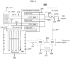
- FIG. 2 is a schematic representation of a system (not claimed) according to disclosed subject matter.
- the system 200 can include a gas turbine generator for combusting air and fuel to produce electrical power.
- the gas turbine generator can include a compressor 220, a combustion chamber 221, and a turbine 222.
- the compressor and turbine can be operated on a single shaft 223.
- a transfer line 201 can be coupled to the compressor for providing air to the compressor.
- One or more transfer lines 202 can be coupled to the combustion chamber for providing compressed air and fuel for combustion.
- the combustion can produce a flue gas, which can be used to drive the turbine.
- a transfer line 203 can transfer flue gas from the combustion chamber to the turbine.
- Coupled refers to the connection of a system component to another system component by any suitable means known in the art.
- the type of coupling used to connect two or more system components can depend on the scale and operability of the system.
- coupling of two or more components of a system can include one or more joints, valves, transfer lines or sealing elements.
- Non-limiting examples of transfer lines include pipes, hose, tubing, and ducting, which can be made of any suitable material, including stainless steel, carbon steel, cast iron, ductile iron, non-ferrous metals and alloys, for example including aluminum, copper, and/or nickel, and non-metallic materials, e.g., concrete and plastic.
- Non-limiting examples of joints include threaded joints, soldered joints, welded joints, compression joints and mechanical joints.
- fittings include coupling fittings, reducing coupling fittings, union fittings, tee fittings, cross fittings and flange fittings.
- valves include gate valves, globe valves, ball valves, butterfly valves and check valves.
- the system 200 can further include a superheater 230, coupled to the gas turbine generator, e.g., via a transfer line 204.
- a feed line 206 can also be coupled to the superheater for providing steam.
- the superheater can include one or more heat exchangers.
- the one or more heat exchangers can be any type suitable for heating gaseous or liquid streams.
- such heat exchangers include shell and tube heat exchangers, plate heat exchangers, plate and shell heat exchangers, adiabatic wheel heat exchangers, and plate fin heat exchangers.
- the transfer line 204 for transferring flue gas to the superheater can include one or more duct burners to provide additional heat to the flue gas.
- the system can further include a steam cracking furnace 240 coupled to the superheater 230, i.e., via a transfer line 207.
- An exhaust line 205 can be coupled to the superheater 230 for removing cooled flue gas from the superheater.
- the exhaust line can be coupled to a heat exchanger for heating combustion air, i.e., a combustion gas line coupled to the steam cracking furnace 240.
- the exhaust line can alternatively be coupled to the steam cracking furnace and the flue gas is used as combustion gas in the steam cracking furnace.
- the steam cracking furnace 240 can include a radiant section and a convection section.
- the radiant section can include one or more burners 247, which may be within a firebox.
- the radiant section can include a radiant coil 246.
- the convection section can also include one or more coils 241, 242, 243, 244, 245.
- the coils can be made of any suitable material and have any suitable thickness for the transfer of heat from the furnace.
- the coils can also include extended surfaces, e.g., fins, to increase heat transfer.
- a feed line 208 can be coupled to the furnace for transferring hydrocarbons to the convection section.
- the feed line can be coupled to a feed preheater 241, i.e., a coil, for heating the hydrocarbons in the convection section.
- the feed line 208 can be combined with the transfer line 207 from the superheater 230 to form a mixed feed line 209 containing hydrocarbons and dilution steam.
- the mixed feed line 209 can be coupled to a mixed preheater 243, i.e., a coil, for heating the hydrocarbons and dilution steam.
- This preheater can be termed the "upper mixed preheater.”
- the mixed feed line can be coupled to a second mixed preheater 245, i.e., a coil, for further heating the hydrocarbons and dilution steam.
- This preheater can be termed the "lower mixed preheater.”
- the system 200 can further include a radiant coil 246 downstream from one or more preheaters 241, 243, 245.
- a product line 210 can be coupled to the radiant coil 246 for transferring the steam cracking products from the furnace 240.
- the product line 210 can be further coupled to a transfer line exchanger 250.
- the transfer line exchanger can be a heat exchanger, e.g., a shell and tube heat exchanger.
- the transfer line exchanger can be a Borsig transfer line exchanger, an Alstom exchanger, a Shaw quench system, or a KBR millisecond primary quench exchanger.
- the transfer line exchanger 250 can be coupled to a steam drum.
- a water feed line 212 can provide water to the steam drum.
- the water feed line can transfer steam and/or water from the transfer line exchanger 250.
- the water feed line can be coupled to an economizer 242 upstream from the transfer line exchanger.
- the economizer can be a coil within the convection section of the steam cracking furnace 240.
- the product line 210 and the water feed line 212 can exchange heat within the transfer line exchanger.
- a cooled product line 211 can remove cooled steam cracking products from the transfer line exchanger.
- a transfer line 213 can transfer the heated water (and steam, if any) to a superheater 244, i.e., a coil, within the convection section of the steam cracking furnace.
- Another transfer line 214 can transfer steam from the superheater 244 to the steam drum.
- the presently disclosed systems can further include additional components and accessories including, but not limited to, one or more gas exhaust lines, cyclones, product discharge lines, reaction zones, heating elements and one or more measurement accessories.
- the one or more measurement accessories can be any suitable measurement accessory known to one of ordinary skill in the art including, but not limited to, pH meters, flow monitors, pressure indicators, pressure transmitters, thermowells, temperature-indicating controllers, gas detectors, analyzers and viscometers.
- the components and accessories can be placed at various locations within the system.
- the methods of the invention and systems of the presently disclosed subject matter can provide advantages over certain existing technologies. Exemplary advantages include efficient superheating of dilution steam for steam cracking operations and generation of electricity.
- the dilution steam was superheated using flue gas from a gas turbine generator to 400°C, 500°C, and 600°C. All three simulations were repeated with light feedstock (i.e ., having a boiling point from 30°C to 260°C) and heavy feedstock (i.e., having a boiling point from 30°C to 390°C). Table 1 shows comparative data from the simulations. Table 1.
- the gas turbine generator uses more fuel, it also produces electricity. If the additional fuel is attributed entirely to electricity generation, the electricity is generated with an efficiency between 60% and 80%.
Landscapes
- Chemical & Material Sciences (AREA)
- Engineering & Computer Science (AREA)
- Oil, Petroleum & Natural Gas (AREA)
- Physics & Mathematics (AREA)
- Thermal Sciences (AREA)
- Chemical Kinetics & Catalysis (AREA)
- General Chemical & Material Sciences (AREA)
- Organic Chemistry (AREA)
- Mechanical Engineering (AREA)
- General Engineering & Computer Science (AREA)
- Production Of Liquid Hydrocarbon Mixture For Refining Petroleum (AREA)
Claims (5)
- Verfahren zur Überhitzung von Verdünnungsdampf zur Verwendung in einem Dampfcrackofen unter Verwendung von Druckluft, wobei das Verfahren umfasst:(a) Verbrennen von Brennstoff in Gegenwart von Druckluft, um ein Rauchgas zu erzeugen, wobei das Rauchgas eine Turbine antreibt, um Elektrizität zu erzeugen;(b) Überhitzen des Verdünnungsdampfes mit dem Rauchgas, wobei der Verdünnungsdampf auf eine Temperatur von 400°C bis 600°C überhitzt wird;(c) Vereinigen des Verdünnungsdampfes mit einem Kohlenwasserstoffe enthaltenden Beschickungsstrom, um einen gemischten Beschickungsstrom zu erzeugen, und ferner das Entspannungsverdampfen des gemischten Beschickungsstroms, so dass mehr als 70 % der Kohlenwasserstoffe vor dem Dampfcracken verdampft werden; und(d) Dampfcracken des gemischten Beschickungsstroms, um einen Produktstrom zu erzeugen, wobei das Verfahren ferner das Verbrennen von Brennstoff in Gegenwart eines Oxidationsmittels umfasst, um den Dampfcrackofen zu erhitzen, wobei das Oxidationsmittel das Rauchgas ist.
- Verfahren nach Anspruch 1, das ferner das Erhitzen des Beschickungsstroms vor dem Vereinigen umfasst.
- Verfahren nach Anspruch 1, das ferner das Erhitzen des gemischten Beschickungsstroms vor dem Dampfcracken umfasst.
- Verfahren nach Anspruch 1, wobei der Produktstrom Ethylen umfasst.
- Verfahren nach Anspruch 1, das ferner das Quenchen des Produktstroms umfasst.
Applications Claiming Priority (2)
| Application Number | Priority Date | Filing Date | Title |
|---|---|---|---|
| US201662280852P | 2016-01-20 | 2016-01-20 | |
| PCT/IB2017/050113 WO2017125833A1 (en) | 2016-01-20 | 2017-01-10 | Methods and systems for superheating dilution steam and generating electricity |
Publications (2)
| Publication Number | Publication Date |
|---|---|
| EP3405553A1 EP3405553A1 (de) | 2018-11-28 |
| EP3405553B1 true EP3405553B1 (de) | 2024-08-21 |
Family
ID=58016742
Family Applications (1)
| Application Number | Title | Priority Date | Filing Date |
|---|---|---|---|
| EP17704536.6A Active EP3405553B1 (de) | 2016-01-20 | 2017-01-10 | Verfahren zur überhitzung von verdünnungsdampf und erzeugung von elektrizität |
Country Status (3)
| Country | Link |
|---|---|
| US (1) | US20200024525A1 (de) |
| EP (1) | EP3405553B1 (de) |
| WO (1) | WO2017125833A1 (de) |
Families Citing this family (5)
| Publication number | Priority date | Publication date | Assignee | Title |
|---|---|---|---|---|
| CA3163958C (en) | 2019-12-09 | 2025-05-13 | Coolbrook Oy | HEAT INTEGRATION INTO A HYDROCARBON PROCESSING PLANT |
| EP4103667A1 (de) | 2020-02-14 | 2022-12-21 | SABIC Global Technologies B.V. | Energieeffizientes dampfcrackverfahren |
| US12649689B2 (en) | 2021-10-13 | 2026-06-09 | Coolbrook Oy | Method and apparatus for heating fluids in processes related to refining and petrochemical industries using rotary generated thermal energy |
| US12553669B2 (en) | 2022-03-22 | 2026-02-17 | Lummus Technology Llc | External combustion air preheat |
| WO2025122393A1 (en) * | 2023-12-08 | 2025-06-12 | Lummus Technology Llc | Adiabatic olefin production |
Citations (1)
| Publication number | Priority date | Publication date | Assignee | Title |
|---|---|---|---|---|
| US20090050530A1 (en) * | 2007-08-21 | 2009-02-26 | Spicer David B | Process and Apparatus for Steam Cracking Hydrocarbon Feedstocks |
Family Cites Families (9)
| Publication number | Priority date | Publication date | Assignee | Title |
|---|---|---|---|---|
| DE2302440C2 (de) * | 1973-01-18 | 1982-09-16 | Linde Ag, 6200 Wiesbaden | Verfahren zur Spaltung von Kohlenwasserstoffen bei hohen Temperaturen unter Verwendung von Prozeßdampf |
| US4172857A (en) * | 1978-04-03 | 1979-10-30 | Arthur G. Mckee & Company | Process and apparatus for ethylene production |
| DE3314132A1 (de) * | 1983-04-19 | 1984-10-25 | Linde Ag, 6200 Wiesbaden | Verfahren zum betreiben einer anlage fuer die spaltung von kohlenwasserstoffen |
| US5669216A (en) | 1990-02-01 | 1997-09-23 | Mannesmann Aktiengesellschaft | Process and device for generating mechanical energy |
| US5647199A (en) | 1995-09-12 | 1997-07-15 | General Electric Co. | Combined-cycle with multi-pressure reheat system |
| FR2796078B1 (fr) * | 1999-07-07 | 2002-06-14 | Bp Chemicals Snc | Procede et dispositif de vapocraquage d'hydrocarbures |
| US7097758B2 (en) * | 2002-07-03 | 2006-08-29 | Exxonmobil Chemical Patents Inc. | Converting mist flow to annular flow in thermal cracking application |
| US20090241551A1 (en) * | 2008-03-26 | 2009-10-01 | Air Liquide Process And Construction Inc. | Cogeneration of Hydrogen and Power |
| KR102387535B1 (ko) | 2014-02-25 | 2022-04-15 | 사우디 베이식 인더스트리즈 코포레이션 | 용광로 공정 에너지 효율 증가 방법 |
-
2017
- 2017-01-10 EP EP17704536.6A patent/EP3405553B1/de active Active
- 2017-01-10 US US16/065,295 patent/US20200024525A1/en not_active Abandoned
- 2017-01-10 WO PCT/IB2017/050113 patent/WO2017125833A1/en not_active Ceased
Patent Citations (1)
| Publication number | Priority date | Publication date | Assignee | Title |
|---|---|---|---|---|
| US20090050530A1 (en) * | 2007-08-21 | 2009-02-26 | Spicer David B | Process and Apparatus for Steam Cracking Hydrocarbon Feedstocks |
Non-Patent Citations (1)
| Title |
|---|
| "Ullmann's Encyclopedia of Industrial Chemistry", 15 April 2009, WILEY-VCH VERLAG, Weinheim, ISBN: 978-3-52-730673-2, article HEINZ ZIMMERMANN ET AL: "Ethylene", XP055007506, DOI: 10.1002/14356007.a10_045.pub3 * |
Also Published As
| Publication number | Publication date |
|---|---|
| WO2017125833A1 (en) | 2017-07-27 |
| US20200024525A1 (en) | 2020-01-23 |
| EP3405553A1 (de) | 2018-11-28 |
Similar Documents
| Publication | Publication Date | Title |
|---|---|---|
| US9346721B2 (en) | Hydrocarbon conversion | |
| US20230115774A1 (en) | Method and apparatus for heating fluids in processes related to refining and petrochemical industries using rotary generated thermal energy | |
| US10703985B2 (en) | Process for cracking hydrocarbon stream using flue gas from gas turbine | |
| JP2025111562A (ja) | オレフィンを生成するための電気炉 | |
| US20200024525A1 (en) | Methods and systems for superheating dilution steam and generating electricity | |
| EP3110909B1 (de) | Verfahren zur erhöhung der energieeffizienz von prozesshochöfen | |
| US20200290939A1 (en) | Methods and systems for olefin production | |
| JP7832363B2 (ja) | 熱回収を伴う炭化水素供給原料を分解するための電気炉 | |
| TWI857530B (zh) | 用於烯烴生產之低二氧化碳排放及氫氣輸入裂解加熱器 | |
| CN104031707A (zh) | 一种工业燃烧用天然气气质调质的方法 | |
| JP2025532505A (ja) | スチームクラッキングのための方法及びシステム | |
| CN116323866A (zh) | 用于蒸汽裂解的方法 | |
| EP3717595A1 (de) | Verfahren und systeme mit verwendung eines reaktorausflussexpanders zur olefinherstellung | |
| US20250188368A1 (en) | Adiabatic olefin production | |
| US20250034066A1 (en) | 100% hydrogen-fired liquid cracking furnace | |
| CN117545824A (zh) | 烯烃生产方法 | |
| EP4386067A1 (de) | Wärmeintegration in einem verfahren zur herstellung von olefinen unter verwendung eines elektrisch erwärmten gases in einem dampfcrackofen | |
| WO2026055606A1 (en) | Hybrid electric and fired heater for olefin production | |
| EA050802B1 (ru) | Крекинг-печь с низким уровнем выбросов co2 и импортом водорода для получения олефинов (варианты) | |
| EA041340B1 (ru) | Способ крекинга потока углеводородов с использованием дымового газа из газовой турбины | |
| SA04250086B1 (ar) | عملية لتكسير الهيدروكربونات باستخدام انابيب محسنة لفرن المفاعل |
Legal Events
| Date | Code | Title | Description |
|---|---|---|---|
| STAA | Information on the status of an ep patent application or granted ep patent |
Free format text: STATUS: UNKNOWN |
|
| STAA | Information on the status of an ep patent application or granted ep patent |
Free format text: STATUS: THE INTERNATIONAL PUBLICATION HAS BEEN MADE |
|
| PUAI | Public reference made under article 153(3) epc to a published international application that has entered the european phase |
Free format text: ORIGINAL CODE: 0009012 |
|
| STAA | Information on the status of an ep patent application or granted ep patent |
Free format text: STATUS: REQUEST FOR EXAMINATION WAS MADE |
|
| 17P | Request for examination filed |
Effective date: 20180816 |
|
| AK | Designated contracting states |
Kind code of ref document: A1 Designated state(s): AL AT BE BG CH CY CZ DE DK EE ES FI FR GB GR HR HU IE IS IT LI LT LU LV MC MK MT NL NO PL PT RO RS SE SI SK SM TR |
|
| AX | Request for extension of the european patent |
Extension state: BA ME |
|
| DAV | Request for validation of the european patent (deleted) | ||
| DAX | Request for extension of the european patent (deleted) | ||
| STAA | Information on the status of an ep patent application or granted ep patent |
Free format text: STATUS: EXAMINATION IS IN PROGRESS |
|
| 17Q | First examination report despatched |
Effective date: 20190702 |
|
| GRAP | Despatch of communication of intention to grant a patent |
Free format text: ORIGINAL CODE: EPIDOSNIGR1 |
|
| STAA | Information on the status of an ep patent application or granted ep patent |
Free format text: STATUS: GRANT OF PATENT IS INTENDED |
|
| INTG | Intention to grant announced |
Effective date: 20240319 |
|
| GRAS | Grant fee paid |
Free format text: ORIGINAL CODE: EPIDOSNIGR3 |
|
| GRAA | (expected) grant |
Free format text: ORIGINAL CODE: 0009210 |
|
| STAA | Information on the status of an ep patent application or granted ep patent |
Free format text: STATUS: THE PATENT HAS BEEN GRANTED |
|
| AK | Designated contracting states |
Kind code of ref document: B1 Designated state(s): AL AT BE BG CH CY CZ DE DK EE ES FI FR GB GR HR HU IE IS IT LI LT LU LV MC MK MT NL NO PL PT RO RS SE SI SK SM TR |
|
| P01 | Opt-out of the competence of the unified patent court (upc) registered |
Free format text: CASE NUMBER: APP_41153/2024 Effective date: 20240711 |
|
| REG | Reference to a national code |
Ref country code: GB Ref legal event code: FG4D |
|
| REG | Reference to a national code |
Ref country code: CH Ref legal event code: EP |
|
| REG | Reference to a national code |
Ref country code: IE Ref legal event code: FG4D |
|
| REG | Reference to a national code |
Ref country code: DE Ref legal event code: R096 Ref document number: 602017084220 Country of ref document: DE |
|
| REG | Reference to a national code |
Ref country code: NL Ref legal event code: FP |
|
| REG | Reference to a national code |
Ref country code: LT Ref legal event code: MG9D |
|
| PG25 | Lapsed in a contracting state [announced via postgrant information from national office to epo] |
Ref country code: NO Free format text: LAPSE BECAUSE OF FAILURE TO SUBMIT A TRANSLATION OF THE DESCRIPTION OR TO PAY THE FEE WITHIN THE PRESCRIBED TIME-LIMIT Effective date: 20241121 |
|
| REG | Reference to a national code |
Ref country code: AT Ref legal event code: MK05 Ref document number: 1715497 Country of ref document: AT Kind code of ref document: T Effective date: 20240821 |
|
| PG25 | Lapsed in a contracting state [announced via postgrant information from national office to epo] |
Ref country code: FI Free format text: LAPSE BECAUSE OF FAILURE TO SUBMIT A TRANSLATION OF THE DESCRIPTION OR TO PAY THE FEE WITHIN THE PRESCRIBED TIME-LIMIT Effective date: 20240821 Ref country code: PL Free format text: LAPSE BECAUSE OF FAILURE TO SUBMIT A TRANSLATION OF THE DESCRIPTION OR TO PAY THE FEE WITHIN THE PRESCRIBED TIME-LIMIT Effective date: 20240821 Ref country code: PT Free format text: LAPSE BECAUSE OF FAILURE TO SUBMIT A TRANSLATION OF THE DESCRIPTION OR TO PAY THE FEE WITHIN THE PRESCRIBED TIME-LIMIT Effective date: 20241223 Ref country code: GR Free format text: LAPSE BECAUSE OF FAILURE TO SUBMIT A TRANSLATION OF THE DESCRIPTION OR TO PAY THE FEE WITHIN THE PRESCRIBED TIME-LIMIT Effective date: 20241122 |
|
| PG25 | Lapsed in a contracting state [announced via postgrant information from national office to epo] |
Ref country code: BG Free format text: LAPSE BECAUSE OF FAILURE TO SUBMIT A TRANSLATION OF THE DESCRIPTION OR TO PAY THE FEE WITHIN THE PRESCRIBED TIME-LIMIT Effective date: 20240821 |
|
| PG25 | Lapsed in a contracting state [announced via postgrant information from national office to epo] |
Ref country code: LV Free format text: LAPSE BECAUSE OF FAILURE TO SUBMIT A TRANSLATION OF THE DESCRIPTION OR TO PAY THE FEE WITHIN THE PRESCRIBED TIME-LIMIT Effective date: 20240821 |
|
| PG25 | Lapsed in a contracting state [announced via postgrant information from national office to epo] |
Ref country code: AT Free format text: LAPSE BECAUSE OF FAILURE TO SUBMIT A TRANSLATION OF THE DESCRIPTION OR TO PAY THE FEE WITHIN THE PRESCRIBED TIME-LIMIT Effective date: 20240821 Ref country code: IS Free format text: LAPSE BECAUSE OF FAILURE TO SUBMIT A TRANSLATION OF THE DESCRIPTION OR TO PAY THE FEE WITHIN THE PRESCRIBED TIME-LIMIT Effective date: 20241221 |
|
| PG25 | Lapsed in a contracting state [announced via postgrant information from national office to epo] |
Ref country code: HR Free format text: LAPSE BECAUSE OF FAILURE TO SUBMIT A TRANSLATION OF THE DESCRIPTION OR TO PAY THE FEE WITHIN THE PRESCRIBED TIME-LIMIT Effective date: 20240821 |
|
| PG25 | Lapsed in a contracting state [announced via postgrant information from national office to epo] |
Ref country code: RS Free format text: LAPSE BECAUSE OF FAILURE TO SUBMIT A TRANSLATION OF THE DESCRIPTION OR TO PAY THE FEE WITHIN THE PRESCRIBED TIME-LIMIT Effective date: 20241121 Ref country code: ES Free format text: LAPSE BECAUSE OF FAILURE TO SUBMIT A TRANSLATION OF THE DESCRIPTION OR TO PAY THE FEE WITHIN THE PRESCRIBED TIME-LIMIT Effective date: 20240821 |
|
| PG25 | Lapsed in a contracting state [announced via postgrant information from national office to epo] |
Ref country code: RS Free format text: LAPSE BECAUSE OF FAILURE TO SUBMIT A TRANSLATION OF THE DESCRIPTION OR TO PAY THE FEE WITHIN THE PRESCRIBED TIME-LIMIT Effective date: 20241121 Ref country code: PT Free format text: LAPSE BECAUSE OF FAILURE TO SUBMIT A TRANSLATION OF THE DESCRIPTION OR TO PAY THE FEE WITHIN THE PRESCRIBED TIME-LIMIT Effective date: 20241223 Ref country code: PL Free format text: LAPSE BECAUSE OF FAILURE TO SUBMIT A TRANSLATION OF THE DESCRIPTION OR TO PAY THE FEE WITHIN THE PRESCRIBED TIME-LIMIT Effective date: 20240821 Ref country code: NO Free format text: LAPSE BECAUSE OF FAILURE TO SUBMIT A TRANSLATION OF THE DESCRIPTION OR TO PAY THE FEE WITHIN THE PRESCRIBED TIME-LIMIT Effective date: 20241121 Ref country code: LV Free format text: LAPSE BECAUSE OF FAILURE TO SUBMIT A TRANSLATION OF THE DESCRIPTION OR TO PAY THE FEE WITHIN THE PRESCRIBED TIME-LIMIT Effective date: 20240821 Ref country code: IS Free format text: LAPSE BECAUSE OF FAILURE TO SUBMIT A TRANSLATION OF THE DESCRIPTION OR TO PAY THE FEE WITHIN THE PRESCRIBED TIME-LIMIT Effective date: 20241221 Ref country code: HR Free format text: LAPSE BECAUSE OF FAILURE TO SUBMIT A TRANSLATION OF THE DESCRIPTION OR TO PAY THE FEE WITHIN THE PRESCRIBED TIME-LIMIT Effective date: 20240821 Ref country code: GR Free format text: LAPSE BECAUSE OF FAILURE TO SUBMIT A TRANSLATION OF THE DESCRIPTION OR TO PAY THE FEE WITHIN THE PRESCRIBED TIME-LIMIT Effective date: 20241122 Ref country code: FI Free format text: LAPSE BECAUSE OF FAILURE TO SUBMIT A TRANSLATION OF THE DESCRIPTION OR TO PAY THE FEE WITHIN THE PRESCRIBED TIME-LIMIT Effective date: 20240821 Ref country code: ES Free format text: LAPSE BECAUSE OF FAILURE TO SUBMIT A TRANSLATION OF THE DESCRIPTION OR TO PAY THE FEE WITHIN THE PRESCRIBED TIME-LIMIT Effective date: 20240821 Ref country code: BG Free format text: LAPSE BECAUSE OF FAILURE TO SUBMIT A TRANSLATION OF THE DESCRIPTION OR TO PAY THE FEE WITHIN THE PRESCRIBED TIME-LIMIT Effective date: 20240821 Ref country code: AT Free format text: LAPSE BECAUSE OF FAILURE TO SUBMIT A TRANSLATION OF THE DESCRIPTION OR TO PAY THE FEE WITHIN THE PRESCRIBED TIME-LIMIT Effective date: 20240821 |
|
| PGFP | Annual fee paid to national office [announced via postgrant information from national office to epo] |
Ref country code: NL Payment date: 20250127 Year of fee payment: 9 |
|
| PG25 | Lapsed in a contracting state [announced via postgrant information from national office to epo] |
Ref country code: SM Free format text: LAPSE BECAUSE OF FAILURE TO SUBMIT A TRANSLATION OF THE DESCRIPTION OR TO PAY THE FEE WITHIN THE PRESCRIBED TIME-LIMIT Effective date: 20240821 Ref country code: DK Free format text: LAPSE BECAUSE OF FAILURE TO SUBMIT A TRANSLATION OF THE DESCRIPTION OR TO PAY THE FEE WITHIN THE PRESCRIBED TIME-LIMIT Effective date: 20240821 Ref country code: RO Free format text: LAPSE BECAUSE OF FAILURE TO SUBMIT A TRANSLATION OF THE DESCRIPTION OR TO PAY THE FEE WITHIN THE PRESCRIBED TIME-LIMIT Effective date: 20240821 |
|
| PG25 | Lapsed in a contracting state [announced via postgrant information from national office to epo] |
Ref country code: EE Free format text: LAPSE BECAUSE OF FAILURE TO SUBMIT A TRANSLATION OF THE DESCRIPTION OR TO PAY THE FEE WITHIN THE PRESCRIBED TIME-LIMIT Effective date: 20240821 |
|
| PG25 | Lapsed in a contracting state [announced via postgrant information from national office to epo] |
Ref country code: CZ Free format text: LAPSE BECAUSE OF FAILURE TO SUBMIT A TRANSLATION OF THE DESCRIPTION OR TO PAY THE FEE WITHIN THE PRESCRIBED TIME-LIMIT Effective date: 20240821 |
|
| PG25 | Lapsed in a contracting state [announced via postgrant information from national office to epo] |
Ref country code: SK Free format text: LAPSE BECAUSE OF FAILURE TO SUBMIT A TRANSLATION OF THE DESCRIPTION OR TO PAY THE FEE WITHIN THE PRESCRIBED TIME-LIMIT Effective date: 20240821 Ref country code: IT Free format text: LAPSE BECAUSE OF FAILURE TO SUBMIT A TRANSLATION OF THE DESCRIPTION OR TO PAY THE FEE WITHIN THE PRESCRIBED TIME-LIMIT Effective date: 20240821 |
|
| REG | Reference to a national code |
Ref country code: DE Ref legal event code: R097 Ref document number: 602017084220 Country of ref document: DE |
|
| PLBE | No opposition filed within time limit |
Free format text: ORIGINAL CODE: 0009261 |
|
| STAA | Information on the status of an ep patent application or granted ep patent |
Free format text: STATUS: NO OPPOSITION FILED WITHIN TIME LIMIT |
|
| 26N | No opposition filed |
Effective date: 20250522 |
|
| REG | Reference to a national code |
Ref country code: DE Ref legal event code: R119 Ref document number: 602017084220 Country of ref document: DE |
|
| REG | Reference to a national code |
Ref country code: CH Ref legal event code: PL |
|
| PG25 | Lapsed in a contracting state [announced via postgrant information from national office to epo] |
Ref country code: SE Free format text: LAPSE BECAUSE OF FAILURE TO SUBMIT A TRANSLATION OF THE DESCRIPTION OR TO PAY THE FEE WITHIN THE PRESCRIBED TIME-LIMIT Effective date: 20240821 |
|
| PG25 | Lapsed in a contracting state [announced via postgrant information from national office to epo] |
Ref country code: LU Free format text: LAPSE BECAUSE OF NON-PAYMENT OF DUE FEES Effective date: 20250110 Ref country code: MC Free format text: LAPSE BECAUSE OF FAILURE TO SUBMIT A TRANSLATION OF THE DESCRIPTION OR TO PAY THE FEE WITHIN THE PRESCRIBED TIME-LIMIT Effective date: 20240821 |
|
| GBPC | Gb: european patent ceased through non-payment of renewal fee |
Effective date: 20250110 |
|
| PG25 | Lapsed in a contracting state [announced via postgrant information from national office to epo] |
Ref country code: DE Free format text: LAPSE BECAUSE OF NON-PAYMENT OF DUE FEES Effective date: 20250801 |
|
| PG25 | Lapsed in a contracting state [announced via postgrant information from national office to epo] |
Ref country code: GB Free format text: LAPSE BECAUSE OF NON-PAYMENT OF DUE FEES Effective date: 20250110 Ref country code: BE Free format text: LAPSE BECAUSE OF NON-PAYMENT OF DUE FEES Effective date: 20250131 |
|
| PG25 | Lapsed in a contracting state [announced via postgrant information from national office to epo] |
Ref country code: FR Free format text: LAPSE BECAUSE OF NON-PAYMENT OF DUE FEES Effective date: 20250131 |
|
| PG25 | Lapsed in a contracting state [announced via postgrant information from national office to epo] |
Ref country code: CH Free format text: LAPSE BECAUSE OF NON-PAYMENT OF DUE FEES Effective date: 20250131 |
|
| REG | Reference to a national code |
Ref country code: BE Ref legal event code: MM Effective date: 20250131 |
|
| PG25 | Lapsed in a contracting state [announced via postgrant information from national office to epo] |
Ref country code: IE Free format text: LAPSE BECAUSE OF NON-PAYMENT OF DUE FEES Effective date: 20250110 |
|
| PG25 | Lapsed in a contracting state [announced via postgrant information from national office to epo] |
Ref country code: CY Free format text: LAPSE BECAUSE OF FAILURE TO SUBMIT A TRANSLATION OF THE DESCRIPTION OR TO PAY THE FEE WITHIN THE PRESCRIBED TIME-LIMIT Effective date: 20240821 |
|
| PG25 | Lapsed in a contracting state [announced via postgrant information from national office to epo] |
Ref country code: TR Free format text: LAPSE BECAUSE OF FAILURE TO SUBMIT A TRANSLATION OF THE DESCRIPTION OR TO PAY THE FEE WITHIN THE PRESCRIBED TIME-LIMIT Effective date: 20240821 |
|
| PG25 | Lapsed in a contracting state [announced via postgrant information from national office to epo] |
Ref country code: LT Free format text: LAPSE BECAUSE OF FAILURE TO SUBMIT A TRANSLATION OF THE DESCRIPTION OR TO PAY THE FEE WITHIN THE PRESCRIBED TIME-LIMIT Effective date: 20240821 |