EP3405420B1 - Leader film on a ribbon supply roll - Google Patents
Leader film on a ribbon supply roll Download PDFInfo
- Publication number
- EP3405420B1 EP3405420B1 EP17742003.1A EP17742003A EP3405420B1 EP 3405420 B1 EP3405420 B1 EP 3405420B1 EP 17742003 A EP17742003 A EP 17742003A EP 3405420 B1 EP3405420 B1 EP 3405420B1
- Authority
- EP
- European Patent Office
- Prior art keywords
- ribbon
- supply
- spool
- tack down
- leader film
- Prior art date
- Legal status (The legal status is an assumption and is not a legal conclusion. Google has not performed a legal analysis and makes no representation as to the accuracy of the status listed.)
- Active
Links
Images
Classifications
-
- B—PERFORMING OPERATIONS; TRANSPORTING
- B41—PRINTING; LINING MACHINES; TYPEWRITERS; STAMPS
- B41J—TYPEWRITERS; SELECTIVE PRINTING MECHANISMS, i.e. MECHANISMS PRINTING OTHERWISE THAN FROM A FORME; CORRECTION OF TYPOGRAPHICAL ERRORS
- B41J33/00—Apparatus or arrangements for feeding ink ribbons or like character-size impression-transfer material
- B41J33/003—Ribbon spools
- B41J33/006—Arrangements to attach the ribbon to the spool
-
- B—PERFORMING OPERATIONS; TRANSPORTING
- B65—CONVEYING; PACKING; STORING; HANDLING THIN OR FILAMENTARY MATERIAL
- B65H—HANDLING THIN OR FILAMENTARY MATERIAL, e.g. SHEETS, WEBS, CABLES
- B65H18/00—Winding webs
- B65H18/28—Wound package of webs
-
- B—PERFORMING OPERATIONS; TRANSPORTING
- B41—PRINTING; LINING MACHINES; TYPEWRITERS; STAMPS
- B41J—TYPEWRITERS; SELECTIVE PRINTING MECHANISMS, i.e. MECHANISMS PRINTING OTHERWISE THAN FROM A FORME; CORRECTION OF TYPOGRAPHICAL ERRORS
- B41J33/00—Apparatus or arrangements for feeding ink ribbons or like character-size impression-transfer material
- B41J33/003—Ribbon spools
-
- B—PERFORMING OPERATIONS; TRANSPORTING
- B41—PRINTING; LINING MACHINES; TYPEWRITERS; STAMPS
- B41J—TYPEWRITERS; SELECTIVE PRINTING MECHANISMS, i.e. MECHANISMS PRINTING OTHERWISE THAN FROM A FORME; CORRECTION OF TYPOGRAPHICAL ERRORS
- B41J17/00—Mechanisms for manipulating page-width impression-transfer material, e.g. carbon paper
- B41J17/32—Detachable carriers or holders for impression-transfer material mechanism
-
- B—PERFORMING OPERATIONS; TRANSPORTING
- B41—PRINTING; LINING MACHINES; TYPEWRITERS; STAMPS
- B41J—TYPEWRITERS; SELECTIVE PRINTING MECHANISMS, i.e. MECHANISMS PRINTING OTHERWISE THAN FROM A FORME; CORRECTION OF TYPOGRAPHICAL ERRORS
- B41J31/00—Ink ribbons; Renovating or testing ink ribbons
- B41J31/10—Ink ribbons having arrangements to facilitate threading through a machine
-
- B—PERFORMING OPERATIONS; TRANSPORTING
- B41—PRINTING; LINING MACHINES; TYPEWRITERS; STAMPS
- B41J—TYPEWRITERS; SELECTIVE PRINTING MECHANISMS, i.e. MECHANISMS PRINTING OTHERWISE THAN FROM A FORME; CORRECTION OF TYPOGRAPHICAL ERRORS
- B41J33/00—Apparatus or arrangements for feeding ink ribbons or like character-size impression-transfer material
-
- B—PERFORMING OPERATIONS; TRANSPORTING
- B41—PRINTING; LINING MACHINES; TYPEWRITERS; STAMPS
- B41J—TYPEWRITERS; SELECTIVE PRINTING MECHANISMS, i.e. MECHANISMS PRINTING OTHERWISE THAN FROM A FORME; CORRECTION OF TYPOGRAPHICAL ERRORS
- B41J33/00—Apparatus or arrangements for feeding ink ribbons or like character-size impression-transfer material
- B41J33/02—Ribbon arrangements
-
- B—PERFORMING OPERATIONS; TRANSPORTING
- B65—CONVEYING; PACKING; STORING; HANDLING THIN OR FILAMENTARY MATERIAL
- B65H—HANDLING THIN OR FILAMENTARY MATERIAL, e.g. SHEETS, WEBS, CABLES
- B65H19/00—Changing the web roll
- B65H19/10—Changing the web roll in unwinding mechanisms or in connection with unwinding operations
- B65H19/102—Preparing the leading end of the replacement web before splicing operation; Adhesive arrangements on leading end of replacement web; Tabs and adhesive tapes for splicing
-
- B—PERFORMING OPERATIONS; TRANSPORTING
- B65—CONVEYING; PACKING; STORING; HANDLING THIN OR FILAMENTARY MATERIAL
- B65H—HANDLING THIN OR FILAMENTARY MATERIAL, e.g. SHEETS, WEBS, CABLES
- B65H2301/00—Handling processes for sheets or webs
- B65H2301/40—Type of handling process
- B65H2301/41—Winding, unwinding
- B65H2301/415—Unwinding
- B65H2301/4151—Starting unwinding process
-
- B—PERFORMING OPERATIONS; TRANSPORTING
- B65—CONVEYING; PACKING; STORING; HANDLING THIN OR FILAMENTARY MATERIAL
- B65H—HANDLING THIN OR FILAMENTARY MATERIAL, e.g. SHEETS, WEBS, CABLES
- B65H2701/00—Handled material; Storage means
- B65H2701/10—Handled articles or webs
- B65H2701/17—Nature of material
- B65H2701/175—Plastic
-
- B—PERFORMING OPERATIONS; TRANSPORTING
- B65—CONVEYING; PACKING; STORING; HANDLING THIN OR FILAMENTARY MATERIAL
- B65H—HANDLING THIN OR FILAMENTARY MATERIAL, e.g. SHEETS, WEBS, CABLES
- B65H2701/00—Handled material; Storage means
- B65H2701/10—Handled articles or webs
- B65H2701/18—Form of handled article or web
- B65H2701/184—Wound packages
- B65H2701/1842—Wound packages of webs
Definitions
- This technical disclosure relates to ribbon supplies that can be used in a number of applications, including card personalization machines such as desktop card personalization machines and central issuance machines.
- the use of ribbon supplies in card personalization machines is well known.
- the ribbon supplies include a supply roll and a take-up roll upon which used ribbon material is wound during use of the ribbon supply.
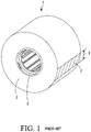
- Figure 1 illustrates an example of a current ribbon supply that includes a supply roll 1 where a ribbon material 3 is wound onto a spool 5. A leading portion 7 of the ribbon material 3 is tacked down onto itself at a tack down zone 9 to prevent unwinding of the ribbon material 3 from the supply roll.
- JP H 07 052506 also discloses such a ribbon spool.
- the leading portion 7 of the ribbon material 3 Prior to or during installation of the ribbon supply, the leading portion 7 of the ribbon material 3 is detached at the tack down zone 9 to form a leader (not shown) that is then attached to or wound around the take-up roll (not shown).
- this causes the bulk, unused ribbon material 3 on the supply roll 1 to be loose during installation of the ribbon supply, possibly allowing the ribbon material 3 to unwind from the supply roll 1 or loosen its winding tension around the supply roll 1. Therefore, additional caution is required by the end user to ensure that the ribbon supply is properly installed or not damaged from unwinding if the supply roll is dropped.
- replacement of the ribbon supply of a card personalization machine may be performed by personnel for whom maintenance of the card personalization machine, including ribbon supply replacement, is only an incidental portion of their job, such as a security guard or a desk clerk, and not by personnel who have special training in such equipment. Therefore, the replacement of the ribbon supply should be made to be relatively intuitive and straightforward.
- a ribbon supply is described where a supply roll containing unused wound ribbon material is provided with a leader film that extends from a tack down bond that prevents unwinding of the unused ribbon material according to claim 1.
- the leader film extends from the tack down bond a sufficient distance to allow the supply roll and optionally the take-up roll to be installed without detaching the tack down bond.
- a ribbon supply includes a supply spool and a ribbon material wound onto the supply spool.
- a tack down bond prevents unwinding of the ribbon material from the supply spool.
- a leader film extends from the tack down bond, with the leader film having a length that is sufficient to allow connection of the leader film to a take-up spool without detaching the tack down bond.
- a ribbon supply as used throughout this application, including the claims, unless otherwise defined, includes a ribbon supply roll and optionally includes a ribbon take-up roll.
- Each of the ribbon supply roll and the ribbon take-up roll has a spool.
- the spool In the case of the ribbon supply roll, the spool may be referred to as a supply spool.
- the spool In the case of the ribbon take-up roll, the spool may be referred to as a take-up spool.
- a consumable ribbon-like material is wound onto the supply spool.
- the ribbon-like material is wound onto (i.e. taken-up on) the take-up spool.
- an end of the ribbon-like material may be pre-attached, directly or indirectly, in any suitable manner to the take-up spool eliminating the need for the end user to attach the end to the take-up spool.
- the end of the ribbon-like material may not be pre-attached to the take-up spool and the end user is required to attach the end, directly or indirectly, to the take-up spool prior to use.
- the ribbon supply can be mounted directly into a machine in which the ribbon supply is to be used.
- the ribbon supply is configured to be removably mounted onto a re-usable cartridge that is removably installable into a machine in which the ribbon supply is to be used.
- the re-useable cartridge can be removed from the machine.
- the ribbon supply can be then be removed from the cartridge and a new ribbon supply mounted onto the cartridge.
- the cartridge can then be reinstalled into the machine.
- the ribbon supply can be any type of consumable ribbon supply that is used in a machine and that from time-to-time needs to be replaced with a new ribbon supply.
- the ribbon supply is for use in a card personalization machine that is designed to personalize one or more plastic cards including, but not limited to financial (e.g., credit, debit, or the like) cards, driver's licenses, national identification cards, business identification cards, gift cards, and other plastic cards which bear personalized data unique to the cardholder and/or which bear other card information.
- the ribbon supply may be used to personalize passports or other non-card-like documents which may also be personalized in a machine that can generally be referred to as a card personalization machine.
- the card personalization machine can be a desktop card personalization machine that is designed to personalize cards one at a time, on the order of tens per hour, or a central issuance system that is designed to simultaneously personalize multiple cards, on the order of hundreds or thousands per hour.
- the machine with which the ribbon supply is used will be described as being a card personalization machine that is intended to encompass a machine that personalizes cards as well as passports and other identification documents.
- the ribbon-like material can be any ribbon-like material that is consumed or used, and that from time-to-time needs replacement.
- ribbon-like materials include, but are not limited to, print ribbons, retransfer films, laminate ribbons, topcoat ribbons, cleaning ribbons, holographic films, embossed character tipping/topping foils, indent foils, and other consumable supplies that have a ribbon-like material that is initially wound on a supply spool and during use the ribbon is wound onto a take-up spool.
- a ribbon, a foil, and a film are intended to refer to similar structures.
- the print ribbon can be a monochromatic (i.e. single color) ribbon or a ribbon with multiple discrete color panels, for example a YMCK print ribbon containing yellow, magenta, cyan and black panels.
- the ribbon supply 10 includes a ribbon supply roll 12.
- the ribbon supply 10 may also include a take-up roll 14. If the take-up roll 14 is not part of the ribbon supply 10, the ribbon supply roll 12 nonetheless functions with the take-up roll 14 which takes up used ribbon material that is supplied from the ribbon supply roll 12.
- the ribbon supply roll 12 includes a supply spool 16 that, in the illustrated embodiment, can be substantially cylindrical with a first open end 18 and a second open end (not shown). However, the supply spool 16 can have shapes other than cylindrical and one or both of the ends can be closed or open.
- the supply spool 16 can have any configuration that is suitable for allowing a ribbon material 20 to be wound thereon prior to use of the ribbon supply 10.
- the take-up roll 14, being part of the ribbon supply 10 can have any shape that is suitable for allowing the ribbon material 20 to be wound thereon as the ribbon material 20 is used during use of the ribbon supply 10.
- the take-up roll 14 includes a take-up spool 22 that can have a construction that, in the illustrated embodiment, can be substantially cylindrical with a first open end 24 and a second open end (not shown).
- the supply spool 16 and the take-up spool 22 can be identical in construction to one another.
- One or both of the spools 16, 22 can have a construction as described in U.S. Patent 6726144 .
- a releasable tack down bond 30 is provided that prevents unwinding of the ribbon material 20 from the ribbon supply roll 12 until after the ribbon supply roll 12 is loaded into the machine.
- a leader film 32 of ribbon-like material extends from the tack down bond 30.
- the leader film 32 extends from the tack down bond 30 a sufficient distance to allow the supply roll 12 to be installed within the machine it is to be used in with the leader film 32 attached to the take-up roll 14 for subsequent take-up of the ribbon material 20 during use, without detaching the tack down bond 30.
- the tack down bond 30 maintains the tightness of the wound ribbon material 20 on the supply roll 12 until the supply roll 12 is installed in the machine and ready for use. Once the supply roll 12 is installed, the tack down bond 30 can be detached to allow unwinding of the ribbon material 20 from the supply spool 16.
- the tack down bond 30 can be created in any manner that is sufficient to prevent unwinding of the ribbon material 20 from the ribbon supply roll 12. Referring to Figure 3 , the tack down bond 30 can be created between an end 50 of an uppermost layer 52 of material that is wound onto the supply spool 16 (shown in Figure 2 ), and a layer 54 of material that underlies the end 50.
- the layers 52, 54 can be of the same material or of different materials.
- the specific layers of material of the supply roll 12 that the tack down bond 30 is formed between is not critical as long as there is a tack down bond 30 that prevents unwinding of the ribbon material 20 from the ribbon supply roll 12 until after the ribbon supply roll 12 is loaded into the machine, and as long as there is a sufficient length of the leader film 32 that extends from the tack down bond 30 to permit installation of the supply roll 12, and attachment of the end of the leader film 32 to the take-up spool 22, prior to the tack down bond 30 being detached.
- the end 50 could be an end of the ribbon material 20 and the layer 54 could also be the ribbon material 20, in which case the tack down bond 30 would be formed between an end of the ribbon material 20 and the ribbon material underlying the end.
- the end 50 could be formed by material that forms the leader film 32, which can be a material that is different than the ribbon material 20 as discussed further below, and layer 54 could be the ribbon material 20 underlying the leader film material. If the material that forms the leader film 32 is wound at least once around the supply roll 12, each of the layers 52, 54 could be formed by the material that forms the leader film 32 in which case the tack down bond 30 would be formed between layers of the leader film material.
- the tack down bond 30 can be created by an adhesive material.
- the adhesive of the tack down bond 30 is sufficient to releasably adhere the upper layer 52 of material and the lower layer 54 of material at the tack down bond 30, yet permit release or detachment of the tack down bond 30 upon application of sufficient force without destroying the ribbon material 20.
- the retaining force provided by the tack down bond can be between about 3.0 lbs to about 5.0 lbs.
- the adhesive material can be an adhesive tape, for example a double-sided adhesive tape.
- Detachment of the tack down bond 30 can occur in any suitable manner.
- detachment can occur automatically via a force applied by the machine in which the ribbon supply 10 is installed.
- the take-up spool 22 can be rotated by the machine in which it is installed to pull the ribbon material 20 from the supply spool 16 for feeding the ribbon material 20 past a device, such as a print head, that will use the ribbon material 20.
- the mechanical pulling force of the take-up spool 22 acting on the ribbon material 20 through the leader film 32 can be sufficient to detach the tack down bond 30 and allow unwinding of the ribbon material 20.
- detachment can occur manually by the user who installed the ribbon supply 10. For example, once the ribbon supply roll 12 is installed and the end of the leader film 32 is attached to the take-up spool 22, the user installing the ribbon supply 10 can manually detach the tack down bond 30 to allow unwinding of the ribbon material 20.
- the tack down bond 30 can have any size that is sufficient to releasably adhere the upper 52 and lower layers 54 and thereby maintain the tightness of the wound ribbon material 20 on the supply roll 12.
- the tack down bond 30 can extend over an entire width W of the supply roll 12, and can extend over a length L.
- the area (e.g. the width W and length L) of the tack down bond 30 can be varied to provide the desired pull force for release.
- the width W and length L can be different than the width W and length L if a weaker adhesive is used.
- the ribbon material 20 is wound in a winding direction D around the supply spool 16.
- the leader film 32 has a first end 34 that extends from the tack down bond 30 and a second end 36 that is secured to the take-up spool 22.
- the leader film 32 includes a first section 38 that extends in the winding direction D from the tack down bond 30.
- the leader film 32 is then folded over itself to form a second section 40 that is connected to the first section 38 at a fold 42.
- the second section 40 extends from the fold 42 to the second end 36.
- the leader film 32 can be formed of any material that is suitable to act as a leader film for connecting the ribbon material 20 to the take-up spool 22.
- the leader film 32 can be formed by a section of the ribbon material 20.
- the leader film 32 can be formed from a material that is different than the ribbon material 20 but which is attached to the end of the ribbon material 20. The attachment between the ribbon material 20 and the leader film 32, if the leader film 32 is different than the ribbon material 20, can occur at any location, for example at or near the tack down bond 30.
- the leader film 32 can have a thickness that is greater than the thickness of the ribbon material 20.
Landscapes
- Impression-Transfer Materials And Handling Thereof (AREA)
- Winding Of Webs (AREA)
Description
- This technical disclosure relates to ribbon supplies that can be used in a number of applications, including card personalization machines such as desktop card personalization machines and central issuance machines.
- The use of ribbon supplies in card personalization machines is well known. The ribbon supplies include a supply roll and a take-up roll upon which used ribbon material is wound during use of the ribbon supply.
Figure 1 illustrates an example of a current ribbon supply that includes asupply roll 1 where aribbon material 3 is wound onto aspool 5. A leadingportion 7 of theribbon material 3 is tacked down onto itself at a tack downzone 9 to prevent unwinding of theribbon material 3 from the supply roll.JP H 07 052506 - Prior to or during installation of the ribbon supply, the leading
portion 7 of theribbon material 3 is detached at the tack downzone 9 to form a leader (not shown) that is then attached to or wound around the take-up roll (not shown). However, this causes the bulk,unused ribbon material 3 on thesupply roll 1 to be loose during installation of the ribbon supply, possibly allowing theribbon material 3 to unwind from thesupply roll 1 or loosen its winding tension around thesupply roll 1. Therefore, additional caution is required by the end user to ensure that the ribbon supply is properly installed or not damaged from unwinding if the supply roll is dropped. In addition, replacement of the ribbon supply of a card personalization machine may be performed by personnel for whom maintenance of the card personalization machine, including ribbon supply replacement, is only an incidental portion of their job, such as a security guard or a desk clerk, and not by personnel who have special training in such equipment. Therefore, the replacement of the ribbon supply should be made to be relatively intuitive and straightforward. - A ribbon supply is described where a supply roll containing unused wound ribbon material is provided with a leader film that extends from a tack down bond that prevents unwinding of the unused ribbon material according to
claim 1. - The leader film extends from the tack down bond a sufficient distance to allow the supply roll and optionally the take-up roll to be installed without detaching the tack down bond. Once the supply roll is installed, the act of completing installation, the end user, or the act of initiating use of the ribbon supply by the machine will detach the tack down bond. Therefore, the tack down bond maintains the tightness of the wound ribbon material on the supply roll until the supply roll is installed in the machine and ready for use.
- In one embodiment, a ribbon supply includes a supply spool and a ribbon material wound onto the supply spool. A tack down bond prevents unwinding of the ribbon material from the supply spool. A leader film extends from the tack down bond, with the leader film having a length that is sufficient to allow connection of the leader film to a take-up spool without detaching the tack down bond.
-
-
Figure 1 illustrates a known configuration of a ribbon supply including a ribbon supply roll and a ribbon take-up roll. -
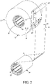
Figure 2 is a perspective view of a ribbon supply described herein including a ribbon supply roll and a ribbon take-up roll. -
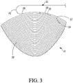
Figure 3 is a detailed close-up view of the area of the tack down bond of the ribbon supply roll. - A ribbon supply as used throughout this application, including the claims, unless otherwise defined, includes a ribbon supply roll and optionally includes a ribbon take-up roll.
- Each of the ribbon supply roll and the ribbon take-up roll has a spool. In the case of the ribbon supply roll, the spool may be referred to as a supply spool. In the case of the ribbon take-up roll, the spool may be referred to as a take-up spool. A consumable ribbon-like material is wound onto the supply spool. During use of the ribbon supply, the ribbon-like material is wound onto (i.e. taken-up on) the take-up spool. Prior to use, an end of the ribbon-like material may be pre-attached, directly or indirectly, in any suitable manner to the take-up spool eliminating the need for the end user to attach the end to the take-up spool. In another embodiment, the end of the ribbon-like material may not be pre-attached to the take-up spool and the end user is required to attach the end, directly or indirectly, to the take-up spool prior to use.
- The ribbon supply can be mounted directly into a machine in which the ribbon supply is to be used. In another embodiment, the ribbon supply is configured to be removably mounted onto a re-usable cartridge that is removably installable into a machine in which the ribbon supply is to be used. When the ribbon supply needs to be replaced, the re-useable cartridge can be removed from the machine. The ribbon supply can be then be removed from the cartridge and a new ribbon supply mounted onto the cartridge. The cartridge can then be reinstalled into the machine.
- The ribbon supply can be any type of consumable ribbon supply that is used in a machine and that from time-to-time needs to be replaced with a new ribbon supply. In one embodiment, the ribbon supply is for use in a card personalization machine that is designed to personalize one or more plastic cards including, but not limited to financial (e.g., credit, debit, or the like) cards, driver's licenses, national identification cards, business identification cards, gift cards, and other plastic cards which bear personalized data unique to the cardholder and/or which bear other card information. In some embodiments, the ribbon supply may be used to personalize passports or other non-card-like documents which may also be personalized in a machine that can generally be referred to as a card personalization machine. The card personalization machine can be a desktop card personalization machine that is designed to personalize cards one at a time, on the order of tens per hour, or a central issuance system that is designed to simultaneously personalize multiple cards, on the order of hundreds or thousands per hour. For sake of convenience, the machine with which the ribbon supply is used will be described as being a card personalization machine that is intended to encompass a machine that personalizes cards as well as passports and other identification documents.
- The ribbon-like material can be any ribbon-like material that is consumed or used, and that from time-to-time needs replacement. Examples of ribbon-like materials include, but are not limited to, print ribbons, retransfer films, laminate ribbons, topcoat ribbons, cleaning ribbons, holographic films, embossed character tipping/topping foils, indent foils, and other consumable supplies that have a ribbon-like material that is initially wound on a supply spool and during use the ribbon is wound onto a take-up spool. As used herein, a ribbon, a foil, and a film are intended to refer to similar structures. In the case of a print ribbon, the print ribbon can be a monochromatic (i.e. single color) ribbon or a ribbon with multiple discrete color panels, for example a YMCK print ribbon containing yellow, magenta, cyan and black panels.
- Referring to
Figure 2 , aribbon supply 10 is illustrated. Theribbon supply 10 includes aribbon supply roll 12. In some embodiments, theribbon supply 10 may also include a take-up roll 14. If the take-up roll 14 is not part of theribbon supply 10, theribbon supply roll 12 nonetheless functions with the take-up roll 14 which takes up used ribbon material that is supplied from theribbon supply roll 12. - The
ribbon supply roll 12 includes asupply spool 16 that, in the illustrated embodiment, can be substantially cylindrical with a firstopen end 18 and a second open end (not shown). However, thesupply spool 16 can have shapes other than cylindrical and one or both of the ends can be closed or open. Thesupply spool 16 can have any configuration that is suitable for allowing aribbon material 20 to be wound thereon prior to use of theribbon supply 10. The take-up roll 14, being part of theribbon supply 10, can have any shape that is suitable for allowing theribbon material 20 to be wound thereon as theribbon material 20 is used during use of theribbon supply 10. In the illustrated example, the take-up roll 14 includes a take-up spool 22 that can have a construction that, in the illustrated embodiment, can be substantially cylindrical with a firstopen end 24 and a second open end (not shown). - The
supply spool 16 and the take-up spool 22 can be identical in construction to one another. One or both of thespools U.S. Patent 6726144 . - Referring to
Figures 2 and3 , a releasable tack downbond 30 is provided that prevents unwinding of theribbon material 20 from theribbon supply roll 12 until after theribbon supply roll 12 is loaded into the machine. In addition, aleader film 32 of ribbon-like material extends from the tack downbond 30. Theleader film 32 extends from the tack down bond 30 a sufficient distance to allow thesupply roll 12 to be installed within the machine it is to be used in with theleader film 32 attached to the take-up roll 14 for subsequent take-up of theribbon material 20 during use, without detaching the tack downbond 30. The tack downbond 30 maintains the tightness of thewound ribbon material 20 on thesupply roll 12 until thesupply roll 12 is installed in the machine and ready for use. Once thesupply roll 12 is installed, the tack downbond 30 can be detached to allow unwinding of theribbon material 20 from thesupply spool 16. - The tack down
bond 30 can be created in any manner that is sufficient to prevent unwinding of theribbon material 20 from theribbon supply roll 12. Referring toFigure 3 , the tack downbond 30 can be created between anend 50 of anuppermost layer 52 of material that is wound onto the supply spool 16 (shown inFigure 2 ), and alayer 54 of material that underlies theend 50. Thelayers supply roll 12 that the tack downbond 30 is formed between is not critical as long as there is a tack downbond 30 that prevents unwinding of theribbon material 20 from theribbon supply roll 12 until after theribbon supply roll 12 is loaded into the machine, and as long as there is a sufficient length of theleader film 32 that extends from the tack downbond 30 to permit installation of thesupply roll 12, and attachment of the end of theleader film 32 to the take-upspool 22, prior to the tack downbond 30 being detached. - For example, the
end 50 could be an end of theribbon material 20 and thelayer 54 could also be theribbon material 20, in which case the tack downbond 30 would be formed between an end of theribbon material 20 and the ribbon material underlying the end. In another embodiment, theend 50 could be formed by material that forms theleader film 32, which can be a material that is different than theribbon material 20 as discussed further below, andlayer 54 could be theribbon material 20 underlying the leader film material. If the material that forms theleader film 32 is wound at least once around thesupply roll 12, each of thelayers leader film 32 in which case the tack downbond 30 would be formed between layers of the leader film material. - The tack down
bond 30 can be created by an adhesive material. The adhesive of the tack downbond 30 is sufficient to releasably adhere theupper layer 52 of material and thelower layer 54 of material at the tack downbond 30, yet permit release or detachment of the tack downbond 30 upon application of sufficient force without destroying theribbon material 20. In one non-limiting example, the retaining force provided by the tack down bond can be between about 3.0 lbs to about 5.0 lbs. However, other forces are possible. In one embodiment, the adhesive material can be an adhesive tape, for example a double-sided adhesive tape. - Detachment of the tack down
bond 30 can occur in any suitable manner. For example, in one embodiment detachment can occur automatically via a force applied by the machine in which theribbon supply 10 is installed. For example, once theribbon supply roll 12 is installed and the end of theleader film 32 is attached to the take-upspool 22, the take-upspool 22 can be rotated by the machine in which it is installed to pull theribbon material 20 from thesupply spool 16 for feeding theribbon material 20 past a device, such as a print head, that will use theribbon material 20. The mechanical pulling force of the take-upspool 22 acting on theribbon material 20 through theleader film 32 can be sufficient to detach the tack downbond 30 and allow unwinding of theribbon material 20. In another embodiment, detachment can occur manually by the user who installed theribbon supply 10. For example, once theribbon supply roll 12 is installed and the end of theleader film 32 is attached to the take-upspool 22, the user installing theribbon supply 10 can manually detach the tack downbond 30 to allow unwinding of theribbon material 20. - The tack down
bond 30 can have any size that is sufficient to releasably adhere the upper 52 andlower layers 54 and thereby maintain the tightness of thewound ribbon material 20 on thesupply roll 12. For example, in one embodiment, the tack downbond 30 can extend over an entire width W of thesupply roll 12, and can extend over a length L. However, the area (e.g. the width W and length L) of the tack downbond 30 can be varied to provide the desired pull force for release. For a strong adhesive the width W and length L can be different than the width W and length L if a weaker adhesive is used. - The
ribbon material 20 is wound in a winding direction D around thesupply spool 16. Theleader film 32 has afirst end 34 that extends from the tack downbond 30 and asecond end 36 that is secured to the take-upspool 22. In the illustrated example, theleader film 32 includes afirst section 38 that extends in the winding direction D from the tack downbond 30. Theleader film 32 is then folded over itself to form asecond section 40 that is connected to thefirst section 38 at afold 42. Thesecond section 40 extends from thefold 42 to thesecond end 36. - The
leader film 32 can be formed of any material that is suitable to act as a leader film for connecting theribbon material 20 to the take-upspool 22. In one embodiment, theleader film 32 can be formed by a section of theribbon material 20. In another embodiment, theleader film 32 can be formed from a material that is different than theribbon material 20 but which is attached to the end of theribbon material 20. The attachment between theribbon material 20 and theleader film 32, if theleader film 32 is different than theribbon material 20, can occur at any location, for example at or near the tack downbond 30. Theleader film 32 can have a thickness that is greater than the thickness of theribbon material 20. In one non-limiting example, theleader film 32 can be formed from a polyester material having a thickness of from about 0.5 2. (=0,0127 mm) mil to about 2.0 mil (0,0508 mm), and in some embodiments about 1.0 mil (=0,0254 mm). - The examples disclosed in this application are to be considered in all respects as illustrative and not limitative. The scope of the invention is indicated by the appended claims .
Claims (9)
- A ribbon supply (10) that is mountable directly into a card personalization machine that is designed to personalize one or more plastic cards or passports, comprising:a supply spool (16);a ribbon material (20) wound onto the supply spool (16), the ribbon material (20) is suitable for use in the card personalization machine;a tack down bond (30) that prevents unwinding of the ribbon material (20) from the supply spool (16);a take-up spool (22) that takes up used ribbon material (20); anda leader film (32) that has a first end (34) that extends from the tack down bond (30) and a second end (36) fixed to the take-up spool (22), wherein the ribbon supply (10) can be directly installed in the card personalization machine prior to detaching the tack down bond (30).
- The ribbon supply (10) of claim 1, wherein the leader film (32) is formed from a material that is different than the ribbon material (20).
- The ribbon supply (10) of claim 1, wherein the leader film (32) has a thickness of from about 0.5 mil to about 2.0 mil.
- The ribbon supply (10) of claim 3, wherein the leader film (32) has a thickness of about 1.0 mil.
- The ribbon supply (10) of claim 1, wherein the leader film (32) is formed from polyester.
- The ribbon supply (10) of claim 1, wherein the ribbon material (20) is a print ribbon, a retransfer film, a laminate ribbon, a topcoat ribbon, a cleaning ribbon, a holographic film, an embossed character tipping/topping foil, or an indent foil.
- The ribbon supply (10) of claim 1, wherein the ribbon material (20) is a monochromatic print- ribbon or a print ribbon with multi-color panels.
- The ribbon supply (10) of claim 1, wherein the ribbon material (20) has a width (W), and the tack down bond (30) extends the entire width (W) of the ribbon material (20).
- The ribbon supply (10) of claim 1, wherein the leader film (32) includes a first section (38) that extends in a winding direction (D) from the tack down bond (30), the leader film (32) is then folded over itself to form a second section (40) that is connected to the first section (38) at a fold (42).
Applications Claiming Priority (2)
| Application Number | Priority Date | Filing Date | Title |
|---|---|---|---|
| US201662280805P | 2016-01-20 | 2016-01-20 | |
| PCT/US2017/014317 WO2017127668A1 (en) | 2016-01-20 | 2017-01-20 | Leader film on a ribbon supply roll |
Publications (3)
| Publication Number | Publication Date |
|---|---|
| EP3405420A1 EP3405420A1 (en) | 2018-11-28 |
| EP3405420A4 EP3405420A4 (en) | 2019-11-06 |
| EP3405420B1 true EP3405420B1 (en) | 2022-07-20 |
Family
ID=59315253
Family Applications (1)
| Application Number | Title | Priority Date | Filing Date |
|---|---|---|---|
| EP17742003.1A Active EP3405420B1 (en) | 2016-01-20 | 2017-01-20 | Leader film on a ribbon supply roll |
Country Status (6)
| Country | Link |
|---|---|
| US (1) | US10195883B2 (en) |
| EP (1) | EP3405420B1 (en) |
| KR (1) | KR102608349B1 (en) |
| CN (1) | CN108473263B (en) |
| MY (1) | MY194374A (en) |
| WO (1) | WO2017127668A1 (en) |
Families Citing this family (1)
| Publication number | Priority date | Publication date | Assignee | Title |
|---|---|---|---|---|
| US20250206565A1 (en) * | 2023-12-20 | 2025-06-26 | Zebra Technologies Corporation | Media Supply with Self-Locking Media Core for Media Processing Devices |
Family Cites Families (13)
| Publication number | Priority date | Publication date | Assignee | Title |
|---|---|---|---|---|
| US5015089A (en) * | 1988-09-22 | 1991-05-14 | Radov Mitchell C | Leader assembly and method |
| IT1257764B (en) * | 1992-03-13 | 1996-02-13 | Gd Spa | COIL OF TAPE MATERIAL |
| JP3089513B2 (en) | 1992-08-05 | 2000-09-18 | ソニー株式会社 | Ribbon cartridge |
| JPH0752506A (en) * | 1993-08-10 | 1995-02-28 | Fujicopian Co Ltd | Replacement transfer ribbon |
| US6100017A (en) * | 1998-03-25 | 2000-08-08 | Fuji Photo Film Co. Ltd. | Roll photo film having seal tape |
| JP2000229465A (en) * | 1999-02-10 | 2000-08-22 | Dainippon Printing Co Ltd | Thermal transfer ribbon |
| US6226023B1 (en) * | 1999-05-10 | 2001-05-01 | Eastman Kodak Company | Thermal printing media pack |
| US6726144B2 (en) | 2001-12-21 | 2004-04-27 | Datacard Corporation | Ribbon core and spindle |
| US6963351B2 (en) * | 2001-12-21 | 2005-11-08 | Datacard Corporation | Radio frequency identification tags on consumable items used in printers and related equipment |
| CN101920863B (en) * | 2002-07-30 | 2011-12-07 | 日立化成工业株式会社 | Method for producing adhesive materials for tapes composed with the same |
| CN100548840C (en) * | 2002-07-30 | 2009-10-14 | 日立化成工业株式会社 | Adhesive material tape connector and method for connecting adhesive material tape |
| KR101526786B1 (en) * | 2014-01-15 | 2015-06-05 | 이모일 | Winding Apparatus For Topping Cord Of Tire |
| KR101600022B1 (en) * | 2014-05-19 | 2016-03-04 | (주)타스지혁 | Anti-mark rolling pipe |
-
2017
- 2017-01-20 KR KR1020187023816A patent/KR102608349B1/en active Active
- 2017-01-20 US US15/411,066 patent/US10195883B2/en active Active
- 2017-01-20 WO PCT/US2017/014317 patent/WO2017127668A1/en not_active Ceased
- 2017-01-20 EP EP17742003.1A patent/EP3405420B1/en active Active
- 2017-01-20 CN CN201780007255.2A patent/CN108473263B/en active Active
- 2017-01-20 MY MYPI2018702437A patent/MY194374A/en unknown
Also Published As
| Publication number | Publication date |
|---|---|
| EP3405420A1 (en) | 2018-11-28 |
| KR20180096817A (en) | 2018-08-29 |
| KR102608349B1 (en) | 2023-11-30 |
| MY194374A (en) | 2022-11-30 |
| EP3405420A4 (en) | 2019-11-06 |
| US10195883B2 (en) | 2019-02-05 |
| CN108473263A (en) | 2018-08-31 |
| WO2017127668A1 (en) | 2017-07-27 |
| CN108473263B (en) | 2020-10-16 |
| US20170203596A1 (en) | 2017-07-20 |
Similar Documents
| Publication | Publication Date | Title |
|---|---|---|
| EP2240922B1 (en) | Continuous strip of thermal wristband/label | |
| US10297172B2 (en) | Perforated, combined receipt and label roll | |
| EP2679382B1 (en) | Machine for manufacturing multi-layer price tags | |
| US20150251464A1 (en) | Tape-like member, tape cartridge, and tape printing device | |
| EP2634762A2 (en) | Two-sided sheet containing a plurality of different travel-related document items | |
| WO2006070569A1 (en) | Double-face printing label printer | |
| JP2005515092A (en) | Radio frequency ID tag attached to consumables used in printer and related device | |
| JP2017052155A (en) | Ink ribbon, ink ribbon cassette and printer | |
| EP2974870A2 (en) | Tape printer for forming self-laminating printed label, tape cassette and ink ribon therefor | |
| WO2005048220A1 (en) | Printable labels roll, for identification badges | |
| US10195883B2 (en) | Leader film on a ribbon supply roll | |
| JP6409469B2 (en) | Self-laminating printing tape, small roll, and self-laminating tape cassette | |
| EP3374190B1 (en) | Ribbon supply mounting | |
| KR19990029071A (en) | Long printable sheet composite | |
| CN106414087B (en) | printer | |
| US20080175643A1 (en) | Ribbon printer | |
| US11285750B2 (en) | Collapsible ribbon supply cartridge | |
| KR102198591B1 (en) | Coated sticker including intermediary product and apparatus for manufacturing the same | |
| JP2019105755A (en) | Base sheet for tag label, tag label using the same, and method and apparatus for producing tag label | |
| JP2012025063A (en) | Continuous slip and method of manufacturing the same | |
| JPH11249570A (en) | Tape for label writer | |
| GB2420548A (en) | Labels and a method of manufacturing labels | |
| JP2017209868A (en) | Card surface information processing method and transfer ribbon |
Legal Events
| Date | Code | Title | Description |
|---|---|---|---|
| STAA | Information on the status of an ep patent application or granted ep patent |
Free format text: STATUS: THE INTERNATIONAL PUBLICATION HAS BEEN MADE |
|
| PUAI | Public reference made under article 153(3) epc to a published international application that has entered the european phase |
Free format text: ORIGINAL CODE: 0009012 |
|
| STAA | Information on the status of an ep patent application or granted ep patent |
Free format text: STATUS: REQUEST FOR EXAMINATION WAS MADE |
|
| 17P | Request for examination filed |
Effective date: 20180716 |
|
| AK | Designated contracting states |
Kind code of ref document: A1 Designated state(s): AL AT BE BG CH CY CZ DE DK EE ES FI FR GB GR HR HU IE IS IT LI LT LU LV MC MK MT NL NO PL PT RO RS SE SI SK SM TR |
|
| AX | Request for extension of the european patent |
Extension state: BA ME |
|
| DAV | Request for validation of the european patent (deleted) | ||
| DAX | Request for extension of the european patent (deleted) | ||
| A4 | Supplementary search report drawn up and despatched |
Effective date: 20191007 |
|
| RIC1 | Information provided on ipc code assigned before grant |
Ipc: B41J 33/00 20060101ALI20190930BHEP Ipc: B65H 18/28 20060101AFI20190930BHEP Ipc: B41J 31/10 20060101ALI20190930BHEP Ipc: B65H 19/10 20060101ALI20190930BHEP Ipc: B41J 33/02 20060101ALI20190930BHEP Ipc: B41J 17/32 20060101ALI20190930BHEP |
|
| GRAP | Despatch of communication of intention to grant a patent |
Free format text: ORIGINAL CODE: EPIDOSNIGR1 |
|
| STAA | Information on the status of an ep patent application or granted ep patent |
Free format text: STATUS: GRANT OF PATENT IS INTENDED |
|
| RIC1 | Information provided on ipc code assigned before grant |
Ipc: B41J 33/00 20060101ALI20220110BHEP Ipc: B41J 31/10 20060101ALI20220110BHEP Ipc: B41J 17/32 20060101ALI20220110BHEP Ipc: B41J 33/02 20060101ALI20220110BHEP Ipc: B65H 19/10 20060101ALI20220110BHEP Ipc: B65H 18/28 20060101AFI20220110BHEP |
|
| INTG | Intention to grant announced |
Effective date: 20220203 |
|
| GRAS | Grant fee paid |
Free format text: ORIGINAL CODE: EPIDOSNIGR3 |
|
| GRAA | (expected) grant |
Free format text: ORIGINAL CODE: 0009210 |
|
| STAA | Information on the status of an ep patent application or granted ep patent |
Free format text: STATUS: THE PATENT HAS BEEN GRANTED |
|
| AK | Designated contracting states |
Kind code of ref document: B1 Designated state(s): AL AT BE BG CH CY CZ DE DK EE ES FI FR GB GR HR HU IE IS IT LI LT LU LV MC MK MT NL NO PL PT RO RS SE SI SK SM TR |
|
| RAP3 | Party data changed (applicant data changed or rights of an application transferred) |
Owner name: ENTRUST CORPORATION |
|
| REG | Reference to a national code |
Ref country code: CH Ref legal event code: EP |
|
| REG | Reference to a national code |
Ref country code: DE Ref legal event code: R096 Ref document number: 602017059653 Country of ref document: DE |
|
| REG | Reference to a national code |
Ref country code: AT Ref legal event code: REF Ref document number: 1505429 Country of ref document: AT Kind code of ref document: T Effective date: 20220815 |
|
| REG | Reference to a national code |
Ref country code: IE Ref legal event code: FG4D |
|
| REG | Reference to a national code |
Ref country code: LT Ref legal event code: MG9D |
|
| REG | Reference to a national code |
Ref country code: NL Ref legal event code: MP Effective date: 20220720 |
|
| PG25 | Lapsed in a contracting state [announced via postgrant information from national office to epo] |
Ref country code: SE Free format text: LAPSE BECAUSE OF FAILURE TO SUBMIT A TRANSLATION OF THE DESCRIPTION OR TO PAY THE FEE WITHIN THE PRESCRIBED TIME-LIMIT Effective date: 20220720 Ref country code: RS Free format text: LAPSE BECAUSE OF FAILURE TO SUBMIT A TRANSLATION OF THE DESCRIPTION OR TO PAY THE FEE WITHIN THE PRESCRIBED TIME-LIMIT Effective date: 20220720 Ref country code: PT Free format text: LAPSE BECAUSE OF FAILURE TO SUBMIT A TRANSLATION OF THE DESCRIPTION OR TO PAY THE FEE WITHIN THE PRESCRIBED TIME-LIMIT Effective date: 20221121 Ref country code: NO Free format text: LAPSE BECAUSE OF FAILURE TO SUBMIT A TRANSLATION OF THE DESCRIPTION OR TO PAY THE FEE WITHIN THE PRESCRIBED TIME-LIMIT Effective date: 20221020 Ref country code: NL Free format text: LAPSE BECAUSE OF FAILURE TO SUBMIT A TRANSLATION OF THE DESCRIPTION OR TO PAY THE FEE WITHIN THE PRESCRIBED TIME-LIMIT Effective date: 20220720 Ref country code: LV Free format text: LAPSE BECAUSE OF FAILURE TO SUBMIT A TRANSLATION OF THE DESCRIPTION OR TO PAY THE FEE WITHIN THE PRESCRIBED TIME-LIMIT Effective date: 20220720 Ref country code: LT Free format text: LAPSE BECAUSE OF FAILURE TO SUBMIT A TRANSLATION OF THE DESCRIPTION OR TO PAY THE FEE WITHIN THE PRESCRIBED TIME-LIMIT Effective date: 20220720 Ref country code: FI Free format text: LAPSE BECAUSE OF FAILURE TO SUBMIT A TRANSLATION OF THE DESCRIPTION OR TO PAY THE FEE WITHIN THE PRESCRIBED TIME-LIMIT Effective date: 20220720 Ref country code: ES Free format text: LAPSE BECAUSE OF FAILURE TO SUBMIT A TRANSLATION OF THE DESCRIPTION OR TO PAY THE FEE WITHIN THE PRESCRIBED TIME-LIMIT Effective date: 20220720 |
|
| REG | Reference to a national code |
Ref country code: AT Ref legal event code: MK05 Ref document number: 1505429 Country of ref document: AT Kind code of ref document: T Effective date: 20220720 |
|
| PG25 | Lapsed in a contracting state [announced via postgrant information from national office to epo] |
Ref country code: PL Free format text: LAPSE BECAUSE OF FAILURE TO SUBMIT A TRANSLATION OF THE DESCRIPTION OR TO PAY THE FEE WITHIN THE PRESCRIBED TIME-LIMIT Effective date: 20220720 Ref country code: IS Free format text: LAPSE BECAUSE OF FAILURE TO SUBMIT A TRANSLATION OF THE DESCRIPTION OR TO PAY THE FEE WITHIN THE PRESCRIBED TIME-LIMIT Effective date: 20221120 Ref country code: HR Free format text: LAPSE BECAUSE OF FAILURE TO SUBMIT A TRANSLATION OF THE DESCRIPTION OR TO PAY THE FEE WITHIN THE PRESCRIBED TIME-LIMIT Effective date: 20220720 Ref country code: GR Free format text: LAPSE BECAUSE OF FAILURE TO SUBMIT A TRANSLATION OF THE DESCRIPTION OR TO PAY THE FEE WITHIN THE PRESCRIBED TIME-LIMIT Effective date: 20221021 |
|
| REG | Reference to a national code |
Ref country code: DE Ref legal event code: R097 Ref document number: 602017059653 Country of ref document: DE |
|
| PG25 | Lapsed in a contracting state [announced via postgrant information from national office to epo] |
Ref country code: SM Free format text: LAPSE BECAUSE OF FAILURE TO SUBMIT A TRANSLATION OF THE DESCRIPTION OR TO PAY THE FEE WITHIN THE PRESCRIBED TIME-LIMIT Effective date: 20220720 Ref country code: RO Free format text: LAPSE BECAUSE OF FAILURE TO SUBMIT A TRANSLATION OF THE DESCRIPTION OR TO PAY THE FEE WITHIN THE PRESCRIBED TIME-LIMIT Effective date: 20220720 Ref country code: DK Free format text: LAPSE BECAUSE OF FAILURE TO SUBMIT A TRANSLATION OF THE DESCRIPTION OR TO PAY THE FEE WITHIN THE PRESCRIBED TIME-LIMIT Effective date: 20220720 Ref country code: CZ Free format text: LAPSE BECAUSE OF FAILURE TO SUBMIT A TRANSLATION OF THE DESCRIPTION OR TO PAY THE FEE WITHIN THE PRESCRIBED TIME-LIMIT Effective date: 20220720 Ref country code: AT Free format text: LAPSE BECAUSE OF FAILURE TO SUBMIT A TRANSLATION OF THE DESCRIPTION OR TO PAY THE FEE WITHIN THE PRESCRIBED TIME-LIMIT Effective date: 20220720 |
|
| PLBE | No opposition filed within time limit |
Free format text: ORIGINAL CODE: 0009261 |
|
| STAA | Information on the status of an ep patent application or granted ep patent |
Free format text: STATUS: NO OPPOSITION FILED WITHIN TIME LIMIT |
|
| PG25 | Lapsed in a contracting state [announced via postgrant information from national office to epo] |
Ref country code: SK Free format text: LAPSE BECAUSE OF FAILURE TO SUBMIT A TRANSLATION OF THE DESCRIPTION OR TO PAY THE FEE WITHIN THE PRESCRIBED TIME-LIMIT Effective date: 20220720 Ref country code: EE Free format text: LAPSE BECAUSE OF FAILURE TO SUBMIT A TRANSLATION OF THE DESCRIPTION OR TO PAY THE FEE WITHIN THE PRESCRIBED TIME-LIMIT Effective date: 20220720 |
|
| P01 | Opt-out of the competence of the unified patent court (upc) registered |
Effective date: 20230513 |
|
| 26N | No opposition filed |
Effective date: 20230421 |
|
| PG25 | Lapsed in a contracting state [announced via postgrant information from national office to epo] |
Ref country code: AL Free format text: LAPSE BECAUSE OF FAILURE TO SUBMIT A TRANSLATION OF THE DESCRIPTION OR TO PAY THE FEE WITHIN THE PRESCRIBED TIME-LIMIT Effective date: 20220720 |
|
| PG25 | Lapsed in a contracting state [announced via postgrant information from national office to epo] |
Ref country code: SI Free format text: LAPSE BECAUSE OF FAILURE TO SUBMIT A TRANSLATION OF THE DESCRIPTION OR TO PAY THE FEE WITHIN THE PRESCRIBED TIME-LIMIT Effective date: 20220720 |
|
| REG | Reference to a national code |
Ref country code: CH Ref legal event code: PL |
|
| PG25 | Lapsed in a contracting state [announced via postgrant information from national office to epo] |
Ref country code: LU Free format text: LAPSE BECAUSE OF NON-PAYMENT OF DUE FEES Effective date: 20230120 |
|
| REG | Reference to a national code |
Ref country code: BE Ref legal event code: MM Effective date: 20230131 |
|
| PG25 | Lapsed in a contracting state [announced via postgrant information from national office to epo] |
Ref country code: LI Free format text: LAPSE BECAUSE OF NON-PAYMENT OF DUE FEES Effective date: 20230131 Ref country code: CH Free format text: LAPSE BECAUSE OF NON-PAYMENT OF DUE FEES Effective date: 20230131 |
|
| PG25 | Lapsed in a contracting state [announced via postgrant information from national office to epo] |
Ref country code: BE Free format text: LAPSE BECAUSE OF NON-PAYMENT OF DUE FEES Effective date: 20230131 |
|
| PG25 | Lapsed in a contracting state [announced via postgrant information from national office to epo] |
Ref country code: IE Free format text: LAPSE BECAUSE OF NON-PAYMENT OF DUE FEES Effective date: 20230120 |
|
| PG25 | Lapsed in a contracting state [announced via postgrant information from national office to epo] |
Ref country code: MC Free format text: LAPSE BECAUSE OF FAILURE TO SUBMIT A TRANSLATION OF THE DESCRIPTION OR TO PAY THE FEE WITHIN THE PRESCRIBED TIME-LIMIT Effective date: 20220720 |
|
| PG25 | Lapsed in a contracting state [announced via postgrant information from national office to epo] |
Ref country code: MC Free format text: LAPSE BECAUSE OF FAILURE TO SUBMIT A TRANSLATION OF THE DESCRIPTION OR TO PAY THE FEE WITHIN THE PRESCRIBED TIME-LIMIT Effective date: 20220720 |
|
| PG25 | Lapsed in a contracting state [announced via postgrant information from national office to epo] |
Ref country code: BG Free format text: LAPSE BECAUSE OF FAILURE TO SUBMIT A TRANSLATION OF THE DESCRIPTION OR TO PAY THE FEE WITHIN THE PRESCRIBED TIME-LIMIT Effective date: 20220720 |
|
| PG25 | Lapsed in a contracting state [announced via postgrant information from national office to epo] |
Ref country code: BG Free format text: LAPSE BECAUSE OF FAILURE TO SUBMIT A TRANSLATION OF THE DESCRIPTION OR TO PAY THE FEE WITHIN THE PRESCRIBED TIME-LIMIT Effective date: 20220720 |
|
| REG | Reference to a national code |
Ref country code: DE Ref legal event code: R082 Ref document number: 602017059653 Country of ref document: DE Representative=s name: PLASSERAUD IP GMBH, DE |
|
| PG25 | Lapsed in a contracting state [announced via postgrant information from national office to epo] |
Ref country code: CY Free format text: LAPSE BECAUSE OF FAILURE TO SUBMIT A TRANSLATION OF THE DESCRIPTION OR TO PAY THE FEE WITHIN THE PRESCRIBED TIME-LIMIT; INVALID AB INITIO Effective date: 20170120 |
|
| PG25 | Lapsed in a contracting state [announced via postgrant information from national office to epo] |
Ref country code: HU Free format text: LAPSE BECAUSE OF FAILURE TO SUBMIT A TRANSLATION OF THE DESCRIPTION OR TO PAY THE FEE WITHIN THE PRESCRIBED TIME-LIMIT; INVALID AB INITIO Effective date: 20170120 |
|
| PG25 | Lapsed in a contracting state [announced via postgrant information from national office to epo] |
Ref country code: TR Free format text: LAPSE BECAUSE OF FAILURE TO SUBMIT A TRANSLATION OF THE DESCRIPTION OR TO PAY THE FEE WITHIN THE PRESCRIBED TIME-LIMIT Effective date: 20220720 |
|
| PGFP | Annual fee paid to national office [announced via postgrant information from national office to epo] |
Ref country code: GB Payment date: 20260127 Year of fee payment: 10 |
|
| PGFP | Annual fee paid to national office [announced via postgrant information from national office to epo] |
Ref country code: DE Payment date: 20260128 Year of fee payment: 10 |
|
| PGFP | Annual fee paid to national office [announced via postgrant information from national office to epo] |
Ref country code: IT Payment date: 20260121 Year of fee payment: 10 |
|
| PGFP | Annual fee paid to national office [announced via postgrant information from national office to epo] |
Ref country code: FR Payment date: 20260126 Year of fee payment: 10 |