EP3404957B1 - Procédé pour mesurer et rapporter une ressource de dispositif à dispositif (d2d) dans un système de communication sans fil, et appareil associé - Google Patents
Procédé pour mesurer et rapporter une ressource de dispositif à dispositif (d2d) dans un système de communication sans fil, et appareil associé Download PDFInfo
- Publication number
- EP3404957B1 EP3404957B1 EP16885260.6A EP16885260A EP3404957B1 EP 3404957 B1 EP3404957 B1 EP 3404957B1 EP 16885260 A EP16885260 A EP 16885260A EP 3404957 B1 EP3404957 B1 EP 3404957B1
- Authority
- EP
- European Patent Office
- Prior art keywords
- resource
- link
- usage rate
- resource usage
- communication
- Prior art date
- Legal status (The legal status is an assumption and is not a legal conclusion. Google has not performed a legal analysis and makes no representation as to the accuracy of the status listed.)
- Active
Links
- 238000004891 communication Methods 0.000 title claims description 107
- 238000000034 method Methods 0.000 title claims description 55
- 238000005259 measurement Methods 0.000 claims description 119
- 230000005540 biological transmission Effects 0.000 claims description 74
- 238000010586 diagram Methods 0.000 description 18
- 239000000969 carrier Substances 0.000 description 17
- 230000011664 signaling Effects 0.000 description 13
- 230000002776 aggregation Effects 0.000 description 8
- 238000004220 aggregation Methods 0.000 description 8
- 230000001413 cellular effect Effects 0.000 description 7
- 101000741965 Homo sapiens Inactive tyrosine-protein kinase PRAG1 Proteins 0.000 description 6
- 102100038659 Inactive tyrosine-protein kinase PRAG1 Human genes 0.000 description 6
- 125000004122 cyclic group Chemical group 0.000 description 6
- 230000006870 function Effects 0.000 description 6
- 230000000737 periodic effect Effects 0.000 description 6
- 230000008054 signal transmission Effects 0.000 description 6
- 230000008859 change Effects 0.000 description 4
- 238000001514 detection method Methods 0.000 description 4
- 230000000694 effects Effects 0.000 description 4
- 238000013468 resource allocation Methods 0.000 description 4
- 230000004044 response Effects 0.000 description 4
- 230000001960 triggered effect Effects 0.000 description 4
- 238000005516 engineering process Methods 0.000 description 3
- 238000007726 management method Methods 0.000 description 3
- 238000001774 stimulated Raman spectroscopy Methods 0.000 description 3
- 241000760358 Enodes Species 0.000 description 2
- 108010003272 Hyaluronate lyase Proteins 0.000 description 2
- 102100031163 Selenide, water dikinase 1 Human genes 0.000 description 2
- 238000009825 accumulation Methods 0.000 description 2
- 230000010267 cellular communication Effects 0.000 description 2
- 239000011159 matrix material Substances 0.000 description 2
- 238000000691 measurement method Methods 0.000 description 2
- 230000010363 phase shift Effects 0.000 description 2
- 101100218322 Arabidopsis thaliana ATXR3 gene Proteins 0.000 description 1
- CIWBSHSKHKDKBQ-JLAZNSOCSA-N Ascorbic acid Chemical compound OC[C@H](O)[C@H]1OC(=O)C(O)=C1O CIWBSHSKHKDKBQ-JLAZNSOCSA-N 0.000 description 1
- 101100151946 Caenorhabditis elegans sars-1 gene Proteins 0.000 description 1
- 102100029768 Histone-lysine N-methyltransferase SETD1A Human genes 0.000 description 1
- 102100032742 Histone-lysine N-methyltransferase SETD2 Human genes 0.000 description 1
- 101000865038 Homo sapiens Histone-lysine N-methyltransferase SETD1A Proteins 0.000 description 1
- 101100149326 Homo sapiens SETD2 gene Proteins 0.000 description 1
- LZHSWRWIMQRTOP-UHFFFAOYSA-N N-(furan-2-ylmethyl)-3-[4-[methyl(propyl)amino]-6-(trifluoromethyl)pyrimidin-2-yl]sulfanylpropanamide Chemical compound CCCN(C)C1=NC(=NC(=C1)C(F)(F)F)SCCC(=O)NCC2=CC=CO2 LZHSWRWIMQRTOP-UHFFFAOYSA-N 0.000 description 1
- 101100533304 Plasmodium falciparum (isolate 3D7) SETVS gene Proteins 0.000 description 1
- 102000003800 Selectins Human genes 0.000 description 1
- 108090000184 Selectins Proteins 0.000 description 1
- 101150117538 Set2 gene Proteins 0.000 description 1
- 230000004913 activation Effects 0.000 description 1
- 230000006978 adaptation Effects 0.000 description 1
- 238000003491 array Methods 0.000 description 1
- 230000006835 compression Effects 0.000 description 1
- 238000007906 compression Methods 0.000 description 1
- 238000013461 design Methods 0.000 description 1
- 230000009365 direct transmission Effects 0.000 description 1
- 230000003993 interaction Effects 0.000 description 1
- 230000007774 longterm Effects 0.000 description 1
- 238000013507 mapping Methods 0.000 description 1
- 238000010295 mobile communication Methods 0.000 description 1
- 238000012986 modification Methods 0.000 description 1
- 230000004048 modification Effects 0.000 description 1
- 238000012545 processing Methods 0.000 description 1
- AAEVYOVXGOFMJO-UHFFFAOYSA-N prometryn Chemical compound CSC1=NC(NC(C)C)=NC(NC(C)C)=N1 AAEVYOVXGOFMJO-UHFFFAOYSA-N 0.000 description 1
- 230000007480 spreading Effects 0.000 description 1
- 238000012546 transfer Methods 0.000 description 1
Images


Classifications
-
- H—ELECTRICITY
- H04—ELECTRIC COMMUNICATION TECHNIQUE
- H04W—WIRELESS COMMUNICATION NETWORKS
- H04W24/00—Supervisory, monitoring or testing arrangements
- H04W24/10—Scheduling measurement reports ; Arrangements for measurement reports
-
- H—ELECTRICITY
- H04—ELECTRIC COMMUNICATION TECHNIQUE
- H04W—WIRELESS COMMUNICATION NETWORKS
- H04W76/00—Connection management
- H04W76/20—Manipulation of established connections
- H04W76/23—Manipulation of direct-mode connections
-
- H—ELECTRICITY
- H04—ELECTRIC COMMUNICATION TECHNIQUE
- H04B—TRANSMISSION
- H04B17/00—Monitoring; Testing
- H04B17/30—Monitoring; Testing of propagation channels
- H04B17/309—Measuring or estimating channel quality parameters
- H04B17/318—Received signal strength
-
- H—ELECTRICITY
- H04—ELECTRIC COMMUNICATION TECHNIQUE
- H04L—TRANSMISSION OF DIGITAL INFORMATION, e.g. TELEGRAPHIC COMMUNICATION
- H04L43/00—Arrangements for monitoring or testing data switching networks
- H04L43/16—Threshold monitoring
-
- H—ELECTRICITY
- H04—ELECTRIC COMMUNICATION TECHNIQUE
- H04W—WIRELESS COMMUNICATION NETWORKS
- H04W24/00—Supervisory, monitoring or testing arrangements
- H04W24/02—Arrangements for optimising operational condition
-
- H—ELECTRICITY
- H04—ELECTRIC COMMUNICATION TECHNIQUE
- H04W—WIRELESS COMMUNICATION NETWORKS
- H04W72/00—Local resource management
- H04W72/12—Wireless traffic scheduling
- H04W72/1263—Mapping of traffic onto schedule, e.g. scheduled allocation or multiplexing of flows
-
- H—ELECTRICITY
- H04—ELECTRIC COMMUNICATION TECHNIQUE
- H04W—WIRELESS COMMUNICATION NETWORKS
- H04W72/00—Local resource management
- H04W72/50—Allocation or scheduling criteria for wireless resources
- H04W72/52—Allocation or scheduling criteria for wireless resources based on load
-
- H—ELECTRICITY
- H04—ELECTRIC COMMUNICATION TECHNIQUE
- H04W—WIRELESS COMMUNICATION NETWORKS
- H04W72/00—Local resource management
- H04W72/50—Allocation or scheduling criteria for wireless resources
- H04W72/54—Allocation or scheduling criteria for wireless resources based on quality criteria
- H04W72/542—Allocation or scheduling criteria for wireless resources based on quality criteria using measured or perceived quality
-
- H—ELECTRICITY
- H04—ELECTRIC COMMUNICATION TECHNIQUE
- H04W—WIRELESS COMMUNICATION NETWORKS
- H04W76/00—Connection management
- H04W76/10—Connection setup
- H04W76/14—Direct-mode setup
Definitions
- the present invention relates to a wireless communication system, and more particularly, to a method of measuring and reporting a D2D (device to device) resource in a wireless communication system supporting D2D communication and an apparatus therefor.
- LTE 3rd generation partnership project long term evolution
- FIG. 1 is a diagram schematically illustrating a network structure of an E-UMTS as an exemplary radio communication system.
- An evolved universal mobile telecommunications system (E-UMTS) is an advanced version of a legacy universal mobile telecommunications system (UMTS) and basic standardization thereof is currently underway in 3GPP.
- E-UMTS may be generally referred to as an LTE system.
- LTE Long Term Evolution
- the E-UMTS includes a user equipment (UE), evolved Node Bs (eNode Bs or eNBs), and an access gateway (AG) which is located at an end of an evolved UMTS terrestrial radio access network (E-UTRAN) and connected to an external network.
- the eNBs may simultaneously transmit multiple data streams for a broadcast service, a multicast service, and/or a unicast service.
- One or more cells are present per eNB.
- a cell is configured to use one of bandwidths of 1.25, 2.5, 5, 10, 15, and 20MHz to provide a downlink or uplink transmission service to multiple UEs. Different cells may be configured to provide different bandwidths.
- the eNB controls data transmission and reception to and from a plurality of UEs.
- the eNB transmits DL scheduling information to notify a corresponding UE of a time/frequency domain within which data is to be transmitted, coding, data size, and hybrid automatic repeat and request (HARQ)-related information by transmitting DL scheduling information to the UE.
- DL scheduling information to notify a corresponding UE of a time/frequency domain within which data is to be transmitted, coding, data size, and hybrid automatic repeat and request (HARQ)-related information by transmitting DL scheduling information to the UE.
- HARQ hybrid automatic repeat and request
- the eNB transmits UL scheduling information to a corresponding UE to inform the UE of an available time/frequency domain, coding, data size, and HARQ-related information.
- An interface for transmitting user traffic or control traffic between eNBs may be used.
- a core network (CN) may include the AG and a network node for user registration of the UE.
- the AG manages mobility of a UE on a tracking area (TA) basis, each TA including a plurality of cells.
- TA tracking area
- WO2015/062671 discloses methods of measuring and reporting a D2D resource by a UE.
- WO2014/089094 also discloses methods of measuring and reporting a D2D resource by a UE.
- a technical task of the present invention is to provide a method of measuring and reporting a D2D resource to adaptively operate in accordance with a load status of D2D communication and an apparatus therefor.
- the present invention is not limited to the above technical problems and other technical objects may be inferred from embodiments of the present invention.
- a method of measuring and reporting a D2D resource by a user equipment supporting D2D (device to device) communication includes measuring a resource usage rate of a first link used for D2D communication, transmitting a measurement report containing the measured resource usage rate to a base station when the measured resource usage rate exceeds a first threshold or is less than a second threshold; and receiving resource reallocation information for off-loading the D2D communication from the base station.
- the resource reallocation information contains a probability value indicating a probability that the first link will be used for the D2D communication, and a probability value indicating a probability that a second link will be used for the D2D communication, the second link being configured in a resource different from a resource of the first link.
- the user equipment offloads the D2D communication to the second link when the second link is selected as a result of performing a link selection based on the probability values.
- a user equipment according to claim 8 is provided.
- the resource reallocation information may contain a probability value indicating a probability that the first link will be used for the D2D communication, and a probability value indicating a probability that a second link will be used for the D2D communication, the second link being configured in a resource different from a resource of the first link.
- the processor may offload the D2D communication to the second link, when the second link is selected as a result of performing a link selection based on the probability values.
- the measurement report includes a flag indicating whether the resource usage rate is high or low, if the resource usage rate exceeds the first threshold, the flag is configured as high, and if the resource usage rate is less than the second threshold, the flag can be configured as low.
- a probability of selecting the second link is configured to be higher than a probability of selecting the first link and if the resource usage rate is less than the second threshold, the probability of selecting the second link can be configured to be lower than the probability of selecting the first link.
- the resource usage rate can be measured using at least one of RSSI (received signal strength indicator), RSRP (reference signal received power), and SA (scheduling assignment) scheduling D2D data which are detected from the first link.
- RSSI received signal strength indicator
- RSRP reference signal received power
- SA scheduleduling assignment
- the user equipment estimates an amount of resources allocated for the D2D data via the SA and measures the resource usage rate by dividing the amount of resources allocated for the D2D data by the total amount of D2D resources.
- the user equipment can measure the resource usage rate by assuming that there is no resource allocated for the SA and the D2D data.
- the total amount of the D2D resources may correspond to remaining resources except a resource in which transmission is performed by the user equipment among a resource region for the D2D data.
- the network offloads D2D communication of the UE according to a load status. By doing so, it is able to more smoothly perform the D2D communication and it is able to more efficiently use a limited resource.
- a base station may be used as a broad meaning including a remote radio head (RRH), an eNB, a transmission point (TP), a reception point (RP), a relay, etc.
- FIG. 2 is a diagram illustrating structures of a control plane and a user plane of a radio interface protocol between a UE and an E-UTRAN based on 3GPP radio access network specifications.
- the control plane refers to a path used for transmission of control messages, which is used by the UE and the network to manage a call.
- the user plane refers to a path in which data generated in an application layer, e.g. voice data or Internet packet data, is transmitted.
- a physical layer of a first layer provides an information transfer service to an upper layer using a physical channel.
- the physical layer is connected to a media access control (MAC) layer of an upper layer via a transmission channel.
- Data is transmitted between the MAC layer and the physical layer via the transmission channel.
- Data is also transmitted between a physical layer of a transmitter and a physical layer of a receiver via a physical channel.
- the physical channel uses time and frequency as radio resources. Specifically, the physical channel is modulated using an orthogonal frequency division multiple Access (OFDMA) scheme in DL and is modulated using a single-carrier frequency division multiple access (SC-FDMA) scheme in UL.
- OFDMA orthogonal frequency division multiple Access
- SC-FDMA single-carrier frequency division multiple access
- the MAC layer of a second layer provides a service to a radio link control (RLC) layer of an upper layer via a logical channel.
- the RLC layer of the second layer supports reliable data transmission.
- the function of the RLC layer may be implemented by a functional block within the MAC layer.
- a packet data convergence protocol (PDCP) layer of the second layer performs a header compression function to reduce unnecessary control information for efficient transmission of an Internet protocol (IP) packet such as an IPv4 or IPv6 packet in a radio interface having a relatively narrow bandwidth.
- IP Internet protocol
- a radio resource control (RRC) layer located at the bottommost portion of a third layer is defined only in the control plane.
- the RRC layer controls logical channels, transmission channels, and physical channels in relation to configuration, reconfiguration, and release of radio bearers.
- a radio bearer refers to a service provided by the second layer to transmit data between the UE and the network.
- the RRC layer of the UE and the RRC layer of the network exchange RRC messages.
- the UE is in an RRC connected mode if an RRC connection has been established between the RRC layer of the radio network and the RRC layer of the UE. Otherwise, the UE is in an RRC idle mode.
- a non-access stratum (NAS) layer located at an upper level of the RRC layer performs functions such as session management and mobility management.
- NAS non-access stratum
- a cell constituting an eNB is set to one of the bandwidths of 1.44, 3, 5, 10, 15 and 20Mhz and provides DL or UL transmission service to a plurality of UEs in the bandwidth.
- Different cells may be configured so as to provide different bandwidths
- DL transmission channels for data transmission from the network to the UE include a broadcast channel (BCH) for transmitting system information, a paging channel (PCH) for transmitting paging messages, and a DL shared channel (SCH) for transmitting user traffic or control messages.
- Traffic or control messages of a DL multicast or broadcast service may be transmitted through the DL SCH or may be transmitted through an additional DL multicast channel (MCH).
- UL transmission channels for data transmission from the UE to the network include a random access channel (RACH) for transmitting initial control messages and a UL SCH for transmitting user traffic or control messages.
- RACH random access channel
- Logical channels which are located at an upper level of the transmission channels and are mapped to the transmission channels, include a broadcast control channel (BCCH), a paging control channel (PCCH), a common control channel (CCCH), a multicast control channel (MCCH), and a multicast traffic channel (MTCH).
- BCCH broadcast control channel
- PCCH paging control channel
- CCCH common control channel
- MCCH multicast control channel
- MTCH multicast traffic channel
- FIG. 3 is a diagram illustrating physical channels used in a 3GPP system and a general signal transmission method using the same.
- the UE When power is turned on or the UE enters a new cell, the UE performs an initial cell search procedure such as acquisition of synchronization with an eNB (S301). To this end, the UE may adjust synchronization with the eNB by receiving a primary synchronization channel (P-SCH) and a secondary synchronization channel (S-SCH) from the eNB and acquire information such as a cell identity (ID). Thereafter, the UE may acquire broadcast information within the cell by receiving a physical broadcast channel from the eNB. In the initial cell search procedure, the UE may monitor a DL channel state by receiving a downlink reference signal (DL RS).
- DL RS downlink reference signal
- the UE may acquire more detailed system information by receiving a physical downlink control channel (PDCCH) and receiving a physical downlink shared channel (PDSCH) based on information carried on the PDCCH (S302).
- PDCCH physical downlink control channel
- PDSCH physical downlink shared channel
- the UE may perform a random access procedure (S303 to S306) with the eNB.
- the UE may transmit a specific sequence through a physical random access channel (PRACH) as a preamble (S303 and S305) and receive a response message to the preamble through the PDCCH and the PDSCH associated with the PDCCH (S304 and S306).
- PRACH physical random access channel
- the UE may additionally perform a contention resolution procedure.
- the UE may receive a PDCCH/PDSCH (S307) and transmit a physical uplink shared channel (PUSCH)/physical uplink control channel (PUCCH) (S308), as a general UL/DL signal transmission procedure.
- PUSCH physical uplink shared channel
- PUCCH physical uplink control channel
- the UE receives downlink control information (DCI) through the PDCCH.
- the DCI includes control information such as resource allocation information for the UE and has different formats according to use purpose thereof.
- control information that the UE transmits to the eNB on UL or receives from the eNB on DL includes a DL/UL acknowledgment/negative acknowledgment (ACK/NACK) signal, a channel quality indicator (CQI), a precoding matrix index (PMI), a rank indicator (RI), and the like.
- ACK/NACK DL/UL acknowledgment/negative acknowledgment
- CQI channel quality indicator
- PMI precoding matrix index
- RI rank indicator
- the UE may transmit the control information such as CQI/PMI/RI through a PUSCH and/or a PUCCH.
- FIG. 4 is a diagram illustrating control channels contained in a control region of one subframe in a DL radio frame.
- one subframe includes 14 OFDM symbols.
- the first to third ones of the 14 OFDM symbols may be used as a control region and the remaining 11 to 13 OFDM symbols may be used as a data region, according to subframe configuration.
- R1 to R4 represent reference signals (RSs) or pilot signals for antennas 0 to 3, respectively.
- the RSs are fixed to a predetermined pattern within the subframe irrespective of the control region and the data region.
- Control channels are allocated to resources unused for RSs in the control region.
- Traffic channels are allocated to resources unused for RSs in the data region.
- the control channels allocated to the control region include a physical control format indicator channel (PCFICH), a physical hybrid-ARQ indicator channel (PHICH), a physical downlink control channel (PDCCH), etc.
- PCFICH physical control format indicator channel
- PHICH physical hybrid-ARQ indicator channel
- PDCCH physical downlink control channel
- the PCFICH physical control format indicator channel, informs a UE of the number of OFDM symbols used for the PDCCH in every subframe.
- the PCFICH is located in the first OFDM symbol and is configured with priority over the PHICH and the PDCCH.
- the PCFICH is composed of 4 resource element groups (REGs) and each of the REGs is distributed over the control region based on a cell ID.
- REG resource element groups
- One REG includes 4 resource elements (REs).
- An RE indicates a minimum physical resource defined as one subcarrier by one OFDM symbol.
- the PCFICH value indicates values of 1 to 3 or values of 2 to 4 depending on bandwidth and is modulated using quadrature phase shift keying (QPSK).
- QPSK quadrature phase shift keying
- the PHICH physical hybrid-ARQ indicator channel
- the PHICH indicates a channel through which DL ACK/NACK information for UL HARQ is transmitted.
- the PHICH includes one REG and is cell-specifically scrambled.
- the ACK/NACK signal is indicated by 1 bit and is modulated using binary phase shift keying (BPSK).
- BPSK binary phase shift keying
- the modulated ACK/NACK signal is spread with a spreading factor (SF) of 2 or 4.
- SF spreading factor
- a plurality of PHICHs mapped to the same resource constitutes a PHICH group.
- the number of PHICHs multiplexed to the PHICH group is determined depending on the number of spreading codes.
- the PHICH (group) is repeated three times to obtain diversity gain in the frequency domain and/or the time domain.
- the PDCCH is allocated to the first n OFDM symbols of a subframe.
- n is an integer equal to or greater than 1, indicated by the PCFICH.
- the PDCCH is composed of one or more control channel elements (CCEs).
- CCEs control channel elements
- the PDCCH informs each UE or UE group of information associated with resource allocation of transmission channels, that is, a paging channel (PCH) and a downlink shared channel (DL-SCH), UL scheduling grant, HARQ information, etc.
- the PCH and the DL-SCH are transmitted through a PDSCH. Therefore, the eNB and the UE transmit and receive data through the PDSCH except for particular control information or service data.
- Information indicating to which UE or UEs PDSCH data is to be transmitted and information indicating how UEs should receive and decode the PDSCH data are transmitted on the PDCCH.
- CRC cyclic redundancy check
- RNTI radio network temporary identity
- DCI format 'C' transport format information (e.g. a transport block size, a modulation scheme, coding information, etc.)
- transport format information e.g. a transport block size, a modulation scheme, coding information, etc.
- the UEs blind-decodes the PDCCH, using RNTI information thereof in a search space. If one or more UEs having RNTI 'A' are present, the UEs receive the PDCCH and receive a PDSCH indicated by 'B' and 'C' based on the received information of the PDCCH.
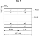
- FIG. 5 is a diagram illustrating the structure of a UL subframe in an LTE system.
- an uplink subframe is divided into a region to which a PUCCH is allocated to transmit control information and a region to which a PUSCH is allocated to transmit user data.
- the PUSCH is allocated to the middle of the subframe, whereas the PUCCH is allocated to both ends of a data region in the frequency domain.
- the control information transmitted on the PUCCH includes an ACK/NACK, a channel quality indicator (CQI) representing a downlink channel state, an RI for Multiple Input and Multiple Output (MIMO), a scheduling request (SR) indicating a request for allocation of UL resources, etc.
- CQI channel quality indicator
- MIMO Multiple Input and Multiple Output
- SR scheduling request
- time capable of transmitting a sounding reference signal in a subframe corresponds to a symbol period lastly positioned in a subframe in a time axis and the sounding reference signal is transmitted through a data transmission band in frequency axis.
- Sounding reference signals of a plurality of UEs transmitted through a last symbol of an identical subframe can be distinguished from each other according to a frequency position.
- FIG. 6 illustrates a structure of a radio frame in an LTE TDD system.
- a radio frame includes two half frames, and each half frame includes four normal subframes each including two slots, and a special subframe including a downlink pilot time slot (DwPTS), a guard period (GP), and an uplink pilot time slot (UpPTS).
- DwPTS downlink pilot time slot
- GP guard period
- UpPTS uplink pilot time slot
- the DwPTS is used for initial cell search, synchronization, or channel estimation in a UE.
- the UpPTS is used for channel estimation in an eNB and uplink transmission synchronization of a UE. That is, the DwPTS is used for downlink transmission and the UpPTS is used for uplink transmission.
- the UpPTS is used for transmission of a PRACH preamble or SRS.
- the GP is a period for removing interference generated in uplink due to multipath delay of a downlink signal between uplink and downlink.
- D, U, and S refer to a downlink subframe, an uplink subframe, and the special subframe.
- Table 1 also shows downlink-to-uplink switch-point periodicity in an uplink/downlink subframe configuration in each system.
- FIG. 7 is a view illustrating concept of a carrier aggregation scheme.
- the carrier aggregation refers to a method of using a plurality of frequency blocks or (logical) cells including uplink resources (or component carriers) and/or downlink resources (or component carriers) by a UE as one large logical frequency band in order to use a wider frequency band by a wireless communication system.
- logical frequency blocks or (logical) cells including uplink resources (or component carriers) and/or downlink resources (or component carriers) by a UE as one large logical frequency band in order to use a wider frequency band by a wireless communication system.
- 'component carrier' will consistently used.
- a system bandwidth has a maximum of 100 MHz as a logical bandwidth.
- the system BW includes five component carriers.
- Each component carrier has a maximum of 20 MHz of bandwidth.
- a component carrier includes one or more physically consecutive subcarriers.
- FIG. 7 illustrates the case in which component carriers have the same bandwidth, the case is purely exemplary, and thus, the component carriers may have different bandwidths.
- FIG. 7 illustrates the case in which the component carriers are adjacent to each other in the frequency domain, FIG. 7 are logically illustrated, and thus, the component carriers may be physically adjacent to each other or may be spaced apart from each other.
- Component carriers can use different center frequencies or use one common center frequency with respect to physically adjacent component carriers. For example, in FIG. 7 , assuming all component carriers are physically adjacent to each other, center frequency A may be used. In addition, assuming that component carriers are not physically adjacent to each other, center frequency A, center frequency B, etc. may be used with respect to the respective component carriers.
- a component carrier may correspond to a system band of a legacy system.
- the component carrier is defined based on a legacy system, and thus, it can be easy to provide backward compatibility and to design the system in a wireless communication environment in which an evolved UE and a legacy UE coexist.
- each component carrier may corresponds to a system band of an LTE system.
- the component carrier may have any one of bandwidths of 1.25, 2.5, 5, 10, and 20 Mhz.
- a frequency band used for communication with each UE is defined in a component carrier unit.
- UE A may use 100 MHz as a system band and perform communication using all five component carriers.
- UEs B 1 to B 5 can use only a bandwidth of 20 MHz and perform communication using one component carrier.
- UEs C 1 and C 2 can use a bandwidth of 40 MHz and communication using two component carries.
- the two component carriers may or may not be logically/physically adjacent to each other.
- UE C 1 refers to the case in which two component carriers that are not adjacent to each other are used and UE C 2 refers to the case in which two adjacent component carriers are used.
- An LTE system may use one downlink component carrier and one uplink component carrier, whereas an LTE-A system may use a plurality of component carriers as illustrated in FIG. 7 .
- a method for scheduling a data channel by a control channel may be classified into a linked carrier scheduling method and a cross carrier scheduling method.
- a control channel transmitted through a specific component carrier schedules only a data channel through the specific component carrier like in a legacy LTE system using a single component carrier.
- a control channel transmitted through a primary component carrier (primary CC) using a carrier indicator field (CIF) schedules a data channel transmitted through a data channel transmitted through the primary CC or a secondary CC.
- primary CC primary component carrier
- CIF carrier indicator field
- a method for controlling, by a UE, uplink transmission power thereof includes open loop power control (OLPC) and closed loop power control (CLPC).
- the former controls power in such a manner that attenuation of a downlink signal from a base station of a cell to which a UE belongs is estimated and compensated for.
- OLPC controls uplink power by increasing uplink transmission power when downlink signal attenuation increases as a distance between the UE and the base station increases.
- the latter controls uplink power in such a manner that the base station directly transmits information (i.e. a control signal) necessary to control uplink transmission power.
- Equation 1 is used to determine transmission power of a UE when a serving cell C transmits only a PUSCH instead of simultaneously transmitting the PUSCH and a PUCCH in a subframe corresponding to a subframe index i in a system that supports carrier aggregation.
- P PUSCH , c i min P CMAX , c i , 10 log 10 M PUSCH , c i + P O _ PUSCH , c j + ⁇ c j ⁇ PL c + ⁇ TF , c i + f c i dBm
- Equation 2 is used to determine PUSCH transmission power when the serving cell C simultaneously transmits the PUCCH and the PUSCH in the subframe corresponding to the subframe index i in a system supporting carrier aggregation.
- P PUSCH , c i min 10 log 10 P ⁇ CMAX , c i ⁇ P ⁇ PUCCH i , 10 log 10 M PUSCH , c i + P O _ PUSCH , c j + ⁇ c j ⁇ PL c + ⁇ TF , c i + f c i dBm
- Equation 1 indicates maximum transmittable power of the UE in the subframe corresponding to the subframe index i
- P ⁇ CMAX,c ( i ) in Equation 2 indicates a linear value of P ⁇ CMAX,c ( i )
- P ⁇ PUCCH ( i ) in Equation 2 indicates a linear value of P ⁇ PUCCH ( i ) ( P ⁇ PUCCH ( i ) indicating PUCCH transmission power in the subframe corresponding to subframe index i ).
- M PUSCH,c ( i ) is a parameter indicating a PUSCH resource allocation bandwidth, which is represented as the number of resource blocks valid for the subframe index i , and is allocated by a base station.
- P O_PUCCH,c ( j ) is a parameter corresponding to the sum of a cell-specific nominal component P O_NOMINAL_PUSCH,c ( j ) provided by a higher layer and a UE-specific component P O_UE_PUSCH,c ( j ) provided by the higher layer and is signaled to the UE by the base station.
- j is 1 in PUSCH transmission/retransmission according to an uplink grant and j is 2 in PUSCH transmission/retransmission according to a random access response.
- referenceSignalPower can be signaled to the UE by the base station via the higher layer.
- f c ( i ) is a value indicating current PUSCH power control adjustment state for the subframe index i and can be represented as a current absolute value or accumulated value.
- ⁇ PUSCH,c ( i - K PUSCH ) is signaled through the PDCCH with DCI format 0/4 or 3/3A in a subframe i - K PUSCH .
- f c (0) is the first value after reset of the accumulated value.
- K PUSCH is defined in LTE as follows.
- K PUSCH has a value of 4.
- K PUSCH has values as shown in Table 2.
- Table 2 TDD UL/DL Configuratio n subframe number i 0 1 2 3 4 5 6 7 8 9 0 - - 6 7 4 - - 6 7 4 1 - - 6 4 - - - 6 4 - 2 - - 4 - - - - 4 - - 3 - - 4 4 4 - - - - - 4 - - 4 4 - - - - - 4 - - - 4 - - - 4 - - - - 4 - - - - 5 - - 4 - - - - - - - 6 - - 7 7 5 - - 7 7 - - 7 -
- the UE attempts to decode a PDCCH in DCI format 0/4 with C-RNTI thereof or to decode a PDCCH in DCI format 3/3A and a DCI format for SPS C-RNTI with TPC-PUSCH-RNTI thereof in each subframe in cases other than DRX state.
- DCI formats 0/4 and 3/3A for the serving cell c are detected in the same subframe, the UE needs to use ⁇ PUSCH,c provided in DCI format 0/4.
- DRX is generated or a subframe having index i is a subframe other than an uplink subframe in TDD, ⁇ PUSCH,c is 0 dB.
- Accumulated ⁇ PUSCH,c which is signaled together with DCI format 0/4 on a PDCCH, is shown in Table 3.
- ⁇ PUSCH,c is 0dB.
- Accumulated ⁇ PUSCH,c which is signaled with DCI format 3/3A on a PDCCH, is one of SET1 of Table 3 or one of SET2 of Table 4, determined by a TPC-index parameter provided by the higher layer.
- P PUCCH i min P CMAX , c i , P 0 _ PUCCH + PL c + h n CQI n HARQ n SR + ⁇ F _ PUCCH F + ⁇ TxD F ′ + g i dBm
- Equation 3 i indicates a subframe index and c indicates a cell index.
- ⁇ TxD ( F ) is provided to the UE by the higher layer.
- ⁇ TxD ( F' ) is 0. Parameters with respect to a cell having the cell index c will now be described.
- P CMAX,c ( i ) indicates maximum transmission power of a UE
- P 0_PUCCH is a parameter corresponding to the sum of cell-specific parameters and signaled by a base station through higher layer signaling
- h ( n ) is a value depending on PUCCH format
- n CQI is the number of information bits with respect to channel quality information (CQI)
- n HARQ indicates the number of HARQ bits.
- ⁇ F_PUCCH ( F ) is a relative value with respect to PUCCH format 1a and a value corresponding to PUCCH format #F, which is signaled by the base station through higher layer signaling.
- g ( i ) indicates a current PUCCH power control adjustment state of a subframe having index i .
- ⁇ msg 2 is a TPC command indicated in a random access response
- ⁇ P rampup corresponds to total power ramp-up from the first to last preambles, provided by the higher layer.
- Tables 5 and 6 show ⁇ PUCCH indicated by a TPC command in DCI formats. Particularly, Table 5 shows ⁇ PUCCH indicated in DCI formats other than DCI format 3A and Table 6 shows ⁇ PUCCH indicated in DCI format 3A.
- Table 5 TPC Command Field in DCI format 1A/1B/1D/1/2A/2B/2C/2D/2/3 ⁇ PUCCH [dB] 0 -1 1 0 2 1 3 3
- Table 6 TPC Command Field in DCI format 3A ⁇ PUCCH [dB] 0 -1 1 1
- Equation 4 in the following corresponds to an equation related to power control of a sounding reference signal (SRS) in LTE system.
- SRS sounding reference signal
- P SRS , c i min P CMAX , c i , P SRS _ OFFSET , c m + 10 log 10 M SRS , c + P O _ PUSCH , c j + ⁇ c j ⁇ PL c + f c i dBm
- Equation 4 i corresponds to a subframe index and c corresponds to a cell index.
- P CMAX,c ( i ) corresponds to maximum power capable of being transmitted by a UE
- P SRS_OFFSET,c ( m ) corresponds to a value configured by an upper layer. If m is 0, it may correspond to a case of transmitting a periodic sounding reference signal. If m is not 0, it may correspond to a case of transmitting an aperiodic sounding reference signal.
- M SRS,c corresponds to a sounding reference signal bandwidth on a subframe index i of a serving cell c and is represented by the number of resource blocks.
- f c ( i ) corresponds to a value indicating a current PUSCH power control adjustment status for a subframe index i of a serving cell c.
- P O_ PUSCH,c ( j ) and ⁇ c ( j ) are also identical to what is mentioned earlier in Equation 1 and 2.
- SRS Sounding Reference Signal
- the SRS is composed of constant amplitude zero auto correlation (CAZAC) sequences.
- ⁇ 2 ⁇ n SRS cs 8
- n SRS cs is a value set to each UE by a higher layer and has an integer value of 0 to 7. Accordingly, the cyclic shift value may have eight values according to n SRS cs .
- CAZAC sequences generated from one CAZAC sequence through cyclic shift have zero correlation values with sequences having different cyclic shift values.
- SRSs of the same frequency domain may be divided according to CAZAC sequence cyclic shift values.
- the SRS of each UE is allocated onto the frequency axis according to a parameter set by the eNB.
- the UE performs frequency hopping of the SRS so as to transmit the SRS with an overall uplink data transmission bandwidth.
- an SRS sequence r SRS ( n ) is first multiplied by an amplitude scaling factor ⁇ SRS and is then mapped to a resource element (RE) having an index (k, 1) from r SRS (0) by Equation 6.
- k 0 denotes a frequency domain start point of an SRS and is defined by Equation 7.
- n b denotes a frequency location index.
- k' 0 for a general uplink subframe is defined by Equation 8
- k ' 0 for an uplink pilot time is defined by Equation 9.
- k TC denotes a transmissionComb parameter signaled to a UE via a higher layer and has a value of 0 or 1.
- n hf is 0 in an uplink pilot time slot of a first half frame and is 0 an uplink pilot slot of a second half frame.
- M sc , b RS is the length, that is, the bandwidth, if the SRS sequence expressed in subcarrier units defined by Equation 10.
- M sc , b RS m SRS , b N sc RB / 2
- Equation 10 m SRS, b is a value signaled from an eNB according to an uplink bandwidth N RB UL .
- the UE may perform frequency hopping of the SRS so as to transmit the SRS with the overall uplink data transmission bandwidth.
- Such frequency hopping is set by a parameter b hop having a value of 0 to 3 received from a higher layer.
- n RRC is a parameter received from a higher layer.
- n b ⁇ 4 n RRC / m SRS , b ⁇ mod N b
- n SRS ⁇ 2 N SP n f + 2 N SP ⁇ 1 ⁇ n s 10 ⁇ + ⁇ T offset T offset _ max ⁇ , for 2 msSRSperiodicityofTDDframestructur ⁇ n f ⁇ 10 + ⁇ n s / 2 ⁇ / T SRS ⁇ , otherwise
- T SRS denotes the periodicity of an SRS and T offset denotes a subframe offset of an SRS.
- n s denotes a slot number and n f denotes a frame number.
- a UE-specific SRS configuration index I SRS for setting the periodicity T SRS and the subframe offset T offset of a UE-specific SRS signal is shown in Table 7 - Table 10 according to FDD and TDD.
- Table 7 and Table 8 indicate a FDD system and a TDD system, respectively.
- Table 7 and Table 8 in the following show a period related to a triggering type 0, i.e., a periodic SRS, and offset information.
- Equation 15 in case of the periodic SRS, transmission is performed in a subframe satisfying Equation 15 in the following in a FDD system or a TDD system where T SRS is greater than 2 (T SRS > 2).
- T SRS is greater than 2
- Equation 15 k SRS corresponds to ⁇ 0, 1, ..., 9 ⁇ in case of the FDD system, whereas k SRS is determined according to Table 9 in the following in case of the TDD system.
- Table 10 and Table 11 in the following show a period related to a triggering type 1, i.e., an aperiodic SRS, and offset information.
- Table 10 and Table 11 indicate a FDD system and a TDD system, respectively.
- SRS Configuration Index I SRS SRS Periodicity T SRS,1 (ms) SRS Subframe Offset T offset ,1 0-1 2 I SRS 2-6 5 I SRS - 2 7-16 10 I SRS - 7 17-31 reserved reserved
- Table 11 SRS Configuration Index I SRS SRS Periodicity T SRS,1 (ms) SRS Subframe Offset T offset ,1 0 2 0, 1 1 2 0,2 2 2 1,2 3 2 0, 3 4 2 1, 3 5 2 0,4 6 2 1,4 7 2 2, 3 8 2 2,4 9 2 3,4 10 - 14 5 I SRS - 10 15 - 24 10 I SRS - 15 25 - 31 reserved reserved reserved reserved
- Equation 17 in the following is used for a FDD system or a TDD system of which T SRS is greater than 2 (T SRS > 2) in the Table 11.
- k SRS corresponds to ⁇ 0, 1, ..., 9 ⁇ .
- D2D communication based on LTE system is explained.
- D2D can be referred to as direct communication between UEs or a sidelink.
- a UE corresponds to a terminal of a user. If such a network device as an eNB transmits and receives a signal according to a D2D communication scheme, the network device can also be considered as a UE as well.
- FIG. 8 is a diagram illustrating exemplary scenarios of D2D communication.
- D2D resources can be allocated from a UL resource (e.g., In case of FDD, a UL frequency resource. In case of TDD, a UL subframe).
- a network controls D2D resources used for D2D communication. The network may allocate a specific resource to a transmission UE or may allocate a pool of D2D resources capable of being selected by a UE.
- a UE In case of out-of-coverage D2D communication, since a network is unable to directly control a D2D resource, a UE uses a preconfigured D2D resource, (c) In case of partial coverage D2D communication, a UE, which is located at the outside of the coverage, is able to use preconfigured parameters. On the contrary, a UE, which is located within the coverage, is able to use a D2D resource obtained from the network.
- a UE1 selects a resource unit (RU) corresponding to a specific D2D resource from a resource pool and the UE1 transmits a D2D signal using the selected RS.
- a resource pool corresponds to a set of D2D resources.
- a UE2 corresponding to a reception UE receives information on a resource pool in which the UE1 is able to transmit a signal and detects a signal of the UE1 in the resource pool. In this case, if the UE1 is located within a connection range of an eNB, the eNB can inform the UE1 of information on the resource pool.
- a resource pool can be informed by a different UE or can be determined by a predetermined resource.
- a resource pool includes a plurality of RUs. A UE selects one or more RUs and may be able to use the selected RUs for transmitting a D2D signal of the UE.
- FIG. 9 is a diagram illustrating an example of a D2D RU. For clarity, assume that the entire frequency resources are divided into the N F number of resource units and the entire time resources are divided into the N T number of resource units.
- a resource pool can be repeated with a period of N T subframes.
- one resource unit may periodically and repeatedly appear.
- an index of a physical RU to which a logical RU is mapped may change based on a predetermined pattern over time to obtain a diversity gain in time domain and/or frequency domain.
- a resource pool may correspond to a set of resource units capable of being used by a UE intending to transmit a D2D signal.
- the aforementioned resource pool can be classified into various types.
- the resource pool can be classified according to contents of a D2D signal transmitted via each resource pool.
- the contents of the D2D signal can be classified as follows and a separate resource pool can be configured according to contents of each D2D signal.
- D2D signal contents of D2D signal are identical to each other, it may use a different resource pool according to a transmission/reception attribute of the D2D signal.
- the D2D data channel or the discovery channel can be transmitted in a different resource pool in consideration of (i) a transmission timing determination scheme of a D2D signal (e.g., whether a D2D signal is transmitted at the time of receiving a synchronization reference signal or the timing to which a prescribed timing advance is added), (ii) a resource allocation scheme (e.g., whether a transmission resource of an individual D2D signal is designated by an eNB or a transmission UE autonomously selects a D2D signal transmission resource from a resource pool), (iii) a signal format (e.g., number of symbols occupied by a D2D signal in a subframe, number of subframes used for transmitting a D2D signal), (iv)
- a transmission timing determination scheme of a D2D signal e.g., whether
- 'D2D' can also be referred to as 'SL (side link)' and 'SA' can also be referred to as PSSCH (physical sidelink control channel).
- a D2D synchronization signal can be referred to as an SSS (sidelink synchronization signal) and the SSS can be transmitted via a PSBCH (physical sidelink broadcast channel).
- the PSBCH transmits most basic information (e.g., system information such as SL-MIB, etc.) prior to D2D communication and can also be referred to as a PD2DSCH (physical D2D synchronization channel).
- a UE transmits a signal (e.g., a discovery signal including an ID of the UE) to a neighboring UE using a discovery channel to inform the neighboring UE of the existence of the UE.
- the discovery channel is referred to as a PSDCH (physical sidelink discovery channel).
- D2D communication of a narrow sense can be distinguished from D2D discovery. For example, if only a UE performing the D2D communication of a narrow sense transmits PSBCH together with SSS (except a UE performing D2D discovery), the SSS can be measured using a DMRS of the PSBCH. An out-of-coverage UE measures the DMRS of the PSBCH (e.g., RSRP, etc.) and may be then able to determine whether or not the UE becomes a synchronization source based on a measurement result.
- DMRS e.g., RSRP, etc.
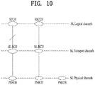
- FIG. 10 is a diagram illustrating SL (side link) channels.
- the SL channels shown in FIG. 9 may correspond to channels for performing D2D communication (e.g., D2D communication of a narrow sense).
- STCH SL traffic channel
- SBCCH SL broadcast control channel
- the STCH transmits user data received from an application and is connected with SL-SCH (SL shared channel).
- the SL-SCH corresponding to a transport channel is connected with PSSCH (physical SL shared channel).
- the SC-SCH signals information necessary for performing synchronization in out-of-coverage or partial coverage scenario or information necessary for performing synchronization between UEs belonging to a different cell.
- the SBCCH is connected with SL-BCH corresponding to a transport channel.
- the SC-BCH is connected with PSBCH.
- PSCCH Physical SL control channel
- PSCCH performs a role similar to a role of PDCCH in legacy communication performed between a UE and an eNB.
- the PSCCH is used to transmit SA (scheduling assignment).
- SA can also be referred to as SCI (sidelink control information).
- a method for an eNB to directly designate a transmission resource of a D2D transmission UE is referred to as a mode 1. If a transmission resource region is configured in advance or an eNB designates the transmission resource region and a UE directly selects a transmission resource from the transmission resource region, it is referred to as a mode 2. In case of performing D2D discovery, if an eNB directly indicates a resource, it is referred to as a type 2. If a UE directly selects a transmission resource from a predetermined resource region or a resource region indicated by the eNB, it is referred to as a type 1.
- an eNB designates a resource to be used for D2D communication in a resource pool.
- a UE selects a resource pool from a set of allocated resource pools and may be able to directly select a D2D resource to be used from the selected resource pool.
- the UE may be in an RRC connected state in the mode 1.
- the UE may be in an RRC idle state or an out-of-coverage state in the mode 2.
- FIG. 11 is a diagram illustrating a D2D communication mode 1.
- a set of subframes i.e., a subframe bitmap
- regions e.g., a control region and a data region.
- Whether or not a subframe is usable for D2D communication can be indicated via a subframe bitmap.
- the SC period starts from a control region including SCI transmitted by PSCCH and 'SubframeBitmapSL' corresponding to a higher layer parameter indicates a subframe in which PSCCH is transmitted.
- a data region starts after the last bit configured by 1 in the 'SubframeBitmapSL'.
- the data region corresponds to a T-RPT bitmap corresponding to a different bitmap.
- the T-RPT bitmap indicates subframes in which data is transmitted.
- a subframe pattern indicated by the T-RPT bitmap is repeated until the SC period ends.
- the last T-RPT bitmap is truncated according to the end of the SC-period.
- the T-RPT bitmap can be dynamically configured and can be differently configured according to each SC-period and each UE.
- the mode 2 operates in a manner of being similar to the mode 1 shown in FIG. 11 . Yet, there is a difference between the mode 1 and the mode 2 in that a start point of a data region is not determined based on SubframeBitmapSL in the mode 2. In the mode 2, the start point of the data region has a fixed offset from a start point of an SC period.
- the UE can measure/report link quality between the UE and a serving eNB to perform link adaptation such as configuration and change of a transmission mode, MCS, and a precoding matrix.
- the UE performs/compares serving cell measurement and neighboring cell measurement for the purpose of handover and the like and can report a measurement result to the eNB.
- the UE measures an eNB-UE link to perform DL transmission, handover, and the like and the eNB performs resource management on each UE based on the measurement report.
- a D2D UE selects a random resource from a time/frequency resource region defined in advance or a time/frequency resource region indicated by an eNB and transmits/receives a D2D discovery/D2D communication signal via the selected resource (e.g., Mode 2 communication, Type 1 discovery).
- a D2D discovery/D2D communication signal via the selected resource (e.g., Mode 2 communication, Type 1 discovery).
- D2D may mean device to device communication that performs direct transmission and reception.
- the D2D can be comprehended as a concept including V2X (vehicle to everything) (e.g., V2I V2V (vehicle-to-vehicle), V2P (vehicle-to-person), P2V (person-to-vehicle), etc.).
- V2X vehicle to everything
- V2I V2V vehicle-to-vehicle
- V2P vehicle-to-person
- P2V person-to-vehicle
- FIG. 12 illustrates an example of D2D communication, more specifically, V2X communication (e.g., V2V, V2I).
- V2X communication e.g., V2V, V2I
- a PC 5 link may correspond to a link which is configured by allocating a part of cellular uplink resources for D2D communication.
- a Uu link corresponds to a link configured for performing communication between an eNB and a UE in a legacy cellular system.
- FIG. 12 illustrates D2D communication between an eNB and a VUE (vehicle UE), by which the present invention may be non-limited.
- D2D communication described in the following can include communication between an RSU (road-side unit) on a road and a vehicle.
- a V2I/V2V supports both (i) a link (e.g., Uu link) configured in a resource for a legacy cellular usage and (ii) a link (e.g., PC 5 link) configured in a resource for a D2D usage.
- a link e.g., Uu link
- a link e.g., PC 5 link
- V2I and V2V communication are performed using the Uu link and/or the PC 5 link.
- a network increases a Uu-based V2I resource (e.g., V2I resource configured on a Uu link) for a VUE1 and a VUE2, since an available D2D resource (e.g., V2I/V2V resource) increases in the aspect of the VUE1 and the VUE2, it may reduce a collision between D2D pairs.
- the Uu link basically corresponds to a resource for performing cellular communication (e.g., communication between an eNB and a UE), if V2I resource increases in the Uu link, a resource for performing cellular communication is reduced and it is difficult for a cellular network to smoothly operate.
- V2I is mainly performed in a PC 5 link resource
- a collision may occur between a V2I resource and a V2V resource.
- V2I transmission UE performs V2V communication with V2V UEs located in the vicinity of the V2I transmission UE
- the V2I may act as strong interference to the V2V communication.
- V2V performance can be degraded.
- the abovementioned resource shortage problem and the collision problem may similarly occur in the V2V communication shown in FIG. 12 .
- a UE e.g., a VUE2
- a collision occurrence probability increases between V2V communications.
- a resource for V2V communication is allocated to the VUE2 on a Uu link, it may have a problem in utilizing a cellular uplink resource.
- a procedure for allocating the additional resource should adaptively operate according to a load status of each link.
- the network can allocate an additional resource or collect a surplus resource.
- a measurement reference value (e.g., a threshold for measuring a resource use) proposed in the following can be defined in advance or signaled by a network.
- a UE can use a measurement result not only for a reporting usage but also for a standard of judgement for autonomously selecting a D2D resource.
- measurement of signal strength/reception power can be applied to a D2D resource as well.
- the RSRP may correspond to reception power of an RS for demodulating a D2D signal or reception power for a D2D synchronization signal. And, whether or not a measured RSRP is valid can be determined according to whether or not decoding is successfully performed on a signal using an RS used for measuring the RSRP. For example, when a UE measures RSRP of a first signal and data associated with the first signal is successfully decoded, it is able to determine that RSRP measurement of the first signal is valid. On the other hand, when a UE measures RSRP of a second signal, if the UE fails to decode data associated with the second signal, it is able to determine that RSRP measurement of the second signal is invalid.
- An invalid measurement result can be identically regarded as a case of not performing measurement.
- a UE may not report the invalid measurement result to a network. If there is no condition for validity, the UE can report a measurement result of reception signal strength/reception power for an RS to the network irrespective of whether or not there is data associated with the RS.
- the RSSI can be interpreted as reception signal strength per unit resource used for measurement.
- Signal strength can be measured according to an OFDM symbol. Or, it may be able to induce signal strength according to a subframe by measuring the signal strength according to a symbol.
- a resource use state can be determined based on a measured value (e.g., RSSI/RSRP) and a specific threshold.
- RSSI energy detection result
- a specific threshold it may be able to determine that resources used for measuring RSSI are occupied more than X %.
- the X may correspond to a predefined value such as 50, 70, or 90, by which the present invention may be non-limited.
- the unit resource can be defined by a PRB pair, a group of PRB pair(s), and the like. If PSSCH is transmitted in a prescribed unit (e.g., 2 PRB pairs), a UE can perform measurement in the unit.
- a resource unit for measuring channel quality can be configured in a manner of being identical to the aforementioned resource unit for measuring signal strength.
- SA scheduling assignment
- PSCCH scheduling control information/control channel of D2D communication
- resource information that schedules a data channel (e.g., PSSCH) which is transmitted after a control channel.
- a D2D UE decodes SA transmitted in a given resource region (e.g., SA resource region) to estimate a resource use state in a PSSCH resource region. For example, if the D2D UE successfully decodes SA, since the D2D UE is able to identify information (e.g., a position and a size of a time/frequency resource) on PSSCH scheduled by the SA, although the D2D UE does not actually receive the PSSCH, the D2D UE is able to identify information on a resource used for transmitting the PSSCH.
- information e.g., a position and a size of a time/frequency resource
- a D2D UE is able to identify a resource use state of PSSCH via SA. If the D2D UE fails to decode the SA, a problem may occur in identifying information on a resource use of PSSCH associated with the SA.
- the present invention proposes a method of estimating a resource use of PSSCH associated with SA when decoding on the SA fails.
- Resource usage rate can be defined as equation 19 in the following, by which the present invention may be non-limited.
- the resource usage rate can be derived from the aforementioned signal strength and/or the channel quality measurement.
- Resource usage rate amount of resources estimated as being currenty used / total amount of resources
- a denominator of the resource usage rate is defined by the total amount of resources.
- the denominator of the resource usage rate can also be defined by an amount of resources capable of being actually measured by a UE among the total amount of the resources. For example, an amount of the remaining resources from which a resource used by a measurement performing UE to perform transmission is eliminated can be used as the denominator of the resource usage rate.
- the resource usage rate can be defined as follows.
- the entire resources becoming a comparison target of the resource usage rate may correspond to actual resources or the entire resources capable of being measured by a UE.
- a size and/or a threshold of a unit resource can be independently defined according to a channel corresponding to a measurement target or a resource pool.
- a unit resource can be defined by 4 PRB pairs in a data resource pool.
- a UE can perform energy detection in a unit of 4 PRB pairs in a given data resource pool.
- the UE can determine the number of unit resources (e.g., 4 PRB pairs) at which a measurement result equal to or greater than a threshold (e.g., X) is measured as the number of resources in use.
- a unit resource can be defined by 2 PRB pairs in an SA resource pool.
- a threshold (e.g., Y) used in the SA resource pool can be independently configured irrespective of the threshold used in the data resource pool.
- a unit resource/threshold for performing measurement can be independently or differently configured in the SA resource pool and the data resource pool.
- a D2D signal can be transmitted on various physical channels.
- a plurality of resource pools can be configured according to each of the physical channels. If measurement and reporting are performed on all existing physical channels and/or the resource pools, it may have a merit that efficiency of resource use is enhanced. However, it may have a demerit in that measurement/reporting overhead of a UE is considerably increased.
- the present invention proposes a method of performing restricted measurement rather than a method of performing measurement on all physical channels/resource pools.
- the measurement can be performed by a periodic reporting (e.g., a measurement result is reported with a prescribed period), an aperiodic reporting (e.g., a measurement result is reported when a network or a device performing D2D resource scheduling requests the measurement result), or an event-triggered reporting (e.g., a measurement result is reported in a specific situation (when a usage rate of a D2D resource is equal to or greater than 70 %)).
- a network can signal a periodic/aperiodic measurement report request or an event-triggered based measurement reporting condition to each D2D UE via DCI or higher layer signaling.
- a D2D UE may piggyback a measurement result on a UL data (e.g., PUSCH) or report the measurement result via a control channel (e.g., PUCCH). Or, a UE may report a measurement result using such a higher layer message as MAC or RRC.
- a UL data e.g., PUSCH
- a control channel e.g., PUCCH
- a UE may report a measurement result using such a higher layer message as MAC or RRC.
- an event-triggered based measurement reporting condition can include a case that a resource usage rate equal to or greater than a prescribed level is maintained for more than prescribed time in a current resource region.
- a measurement result can be reported via a physical layer (e.g., PUCCH/PUSCH) when measurement information is promptly requested.
- a network may ask a UE to report a measurement result to the network to check whether or not a specific time/frequency resource or a resource region is currently used.
- an eNB can indicate a time/frequency resource or a resource region to be measured to a UE via physical layer signaling or higher layer signaling.
- a UE can report a measurement report to an eNB via higher layer signaling such as MAC, RRC or the like when measurement information of a relatively long period is required. For example, when an eNB asks a UE to report a measurement result to the eNB to periodically or aperiodically identify a status of a specific resource pool, the UE can report the measurement result to the eNB via higher layer signaling such as MAC or RRC.
- higher layer signaling such as MAC, RRC or the like
- a threshold is configured based on hysteresis, it may be able to more stably manage resources compared to a case of determining whether to use a resource based on a single threshold.
- the hysteresis-based threshold configuration can be used as a reference for selecting a resource to be used.
- a problem may occur.
- the problem is explained in more detail. For clarity, assume that a resource usage rate corresponds to 50 % as a single threshold. If a resource usage rate measured by a UE becomes 51 %, since it is determined as the resource usage rate is high, a network configures an additional resource and changes a system parameter to offload UE data from a corresponding resource. However, the measured resource usage rate may become 49 %. In this case, since it is determined as the resource usage rate is low, the network collects the additionally configured resource and changes the system parameter to offload the UE data again. In particular, if an operation is performed based on a single threshold, it may have a problem in that the system parameter is too frequently changed.
- the problem above can be solved by using a plurality of the thresholds. For example, assume that two thresholds including a resource usage rate of 80 % and a resource usage rate of 40 % are used, respectively. If the resource usage rate exceeds 80 %, a UE reports that the resource usage rate is high to a network and the network allocates an additional resource to the UE. If the resource usage rate is not going down to a resource usage rate equal to or less than 40 % after the additional resource is allocated, since the UE does not report that the resource usage rate is low, it may be able to solve a problem of repeating additional resource configuration and resource collection.
- the location information can be replaced with RSRP for a cell signal capable of being measured by the UE.
- RSRP for a serving cell signal and/or RSRP for a neighboring cell can be used as the location information. If a UE reports RSRP of a serving cell and RSRP of a neighboring cell, the serving cell estimates a location of the UE based on the RSRP and may be then able to adjust a D2D resource of a corresponding region (i.e., the estimated location).
- a network can control a link selection/usage rate of each UE. For example, if there is no separate indication from the network, a UE can be configured to use a PC5 link only to perform D2D communication.
- a network indicates UEs to configure a selection ratio of a Uu link and a selection ratio of a PC5 link by 40 % and 60 %, respectively, and select/use a link.
- a ratio as 40%:60% signaled from the network can be comprehended as a link selection probability.
- it may be able to comprehend as a probability for a UE to select/use a Uu link for D2D communication corresponds to 40 % and a probability for the UE to select/use a PC5 link for D2D communication corresponds to 60 %.
- a UE can select a link and/or a resource to be used for performing D2D communication based on a probability function.
- a network or a device performing D2D resource scheduling receives a measurement report from a UE, the network or the device may newly allocate a D2D resource, allocate a D2D resource in addition to a legacy D2D resource, or reduce a legacy D2D resource.
- a resource usage rate may considerably change in every moment.
- a default link can be set or signaled to a UE in advance to perform D2D communication. If a usage rate of the default link exceeds X %, a network can signal the UE to use an additional link. In this case, a selection probability of the additional link and a selection probability of the default link can be defined in advance or can be signaled by the network.
- the default link and the additional link may correspond to a PC5 link and a Uu link, respectively, by which the present invention may be non-limited.
- the PC5 link is configured as the default link
- the Uu link can also be configured as the default link. This can be defined in advance or can be configured via signaling.
- a usage rate of the PC5 link measured by a UE e.g., VUE1 exceeds 80 %
- a network configures a probability of selecting the Uu link by 80 % and a probability of selecting th PC5 link by 20 % for V2I communication in a cell.
- the network can signal the UE to select a V2I resource based on the probabilities.
- the network may prohibit the UE from using the Uu link or lower the probability of selecting the Uu link.
- the network can perform the configuration of the link selection probability and the signaling procedure during a prescribed period or according to the occurrence of a specific event (e.g., if a usage rate of a specific link exceeds 80 %).
- a PC5 link can be configured as a default link for V2V/V2I.
- a selection probability of the PC5 link and a selectin probability of the Uu link can be signaled via network signaling.
- a network changes a link selection probability based on a resource usage rate reported by a UE and can inform the UE of the changed link selection probability.
- a default link between UEs used in D2D can be restricted to a Pcell (or Scell) resource.
- the Pcell (or Scell) resource is measured, if a usage rate of the Pcell (or Scell) resource is high, it may be able to configure the Pcell (or Scell) resource to be used.
- a UE performs the aforementioned measurement in a given resource and can perform D2D communication using a measurement result. For example, if a UE is unable to report a measurement result to a network or is located at environment incapable of receiving a configuration of a resource region from the network, the UE can (re)select a resource region and/or a link using a measurement result.
- a measurement is performed by a transmission UE (or reception UE) and the transmission UE can select a transmission resource from a resource region.
- a D2D connection is established through interaction (e.g., signal exchange) between UEs, each of the UEs can exchange a measurement result each other in the procedure of establishing the D2D connection.
- a UE can determine a resource for a D2D pair consisting of the UE and the partner UE based on the exchanged measurement result.
- the UE can report reception performance of the UE using a periodic scheme, an aperiodic scheme, or an event-triggered scheme. For example, the UE can report a BLER (block error rate) for a D2D message received by the UE to a network.
- the network receives BLER reports from a plurality of UEs and can identify an overall D2D resource use state based on the BLER reports. Having identified the D2D resource use state, the network can perform the aforementioned additional link allocation and the resource collection.
- the UE can report information on a resource in which the D2D message is received to the network.
- the network is able to determine a currently used resource.
- the information on the resource can include at least one of a PRB pair(s), a resource pool, T-RPT, a resource position in frequency domain, and an amount of resources, by which the present invention may be non-limited.
- FIG. 13 illustrates a measurement and reporting method according to one embodiment of the present invention. Explanation on contents overlapped with the aforementioned description is omitted.
- a UE measures a resource usage rate of a first link currently used to perform D2D communication [S1305].
- the first link may correspond to a PC5 link.
- the resource usage rate can be measured using at least one of RSSI (received signal strength indicator), RSRP (reference signal received power), and SA (scheduling assignment) scheduling D2D data which are detected from the first link.
- the UE estimates an amount of resources allocated for D2D data through the SA and can measure the resource usage rate by dividing the amount of resources allocated for D2D data by the total amount of D2D resources. If decoding of the SA fails and RSRP of the SA is less than a threshold, the UE can measure the resource usage rate under the assumption that there is no resource allocated for the SA and the D2D data.
- the total amount of D2D resources may correspond to the remaining resources except a resource in which transmission is performed by the UE among a D2D data resource region.
- the UE can transmit a measurement report to a base station [S1310]. For example, if a measured resource usage rate exceeds a first threshold or is less than a second threshold, the UE can transmit a measurement report including the measured resource usage rate to the base station.
- the measurement report can include a flag indicating whether a resource usage rate is high or low. If the resource usage rate exceeds the first threshold, the flag can be configured as high. If the resource usage rate is less than the second threshold, the flag can be configured as low.
- the UE receives resource reallocation information from the base station [S1315].
- the resource reallocation information can be used for off-loading D2D communication.
- the resource reallocation information is not restricted by the terminology.
- the resource reallocation information can a probability value indicating a probability that the first link will be used for the D2D communication, and a probability value indicating a probability that a second link will be used for the D2D communication, the second link being configured in a resource different from a resource of the first link.
- the second link may correspond to a Uu link. For example, if a resource usage rate exceeds the first threshold, a probability of selecting the second link can be configured to be higher than a probability of selecting the first link. On the contrary, if the resource usage rate is less than the second threshold, a probability of selecting the second link can be configured to be lower than a probability of selecting the first link.
- the UE can offload D2D communication on the first link to the second link [S1320]. For example, when the second link is selected as a result of performing a link selection based on the probability values the UE can offload D2D communication performed on the first link to the second link.
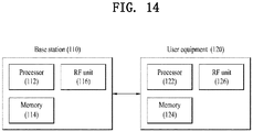
- FIG. 14 is a view illustrating a user equipment (UE) and a base station (BS) according to an embodiment of the present invention.
- the BS and UE illustrated in FIG. 14 may perform signal transmitting/receiving operations according to aforementioned embodiments.
- a wireless communication system includes a BS 110 and a UE 120.
- a transmitter may be a part of the BS 110, and a receiver may be a part of the UE 120.
- a transmitter may be a part of the UE 120, and a receiver may be a part of the BS 110.
- the BS 110 includes a processor 112, a memory 114, and a Radio Frequency (RF) unit 116.
- the processor 112 may be configured so as to implement the procedures and/or methods proposed in the present invention.
- the memory 114 is connected to the processor 112 and stores various pieces of information related to operations of the processor 112.
- the RF unit 116 is connected to the processor 112 and transmits and/or receives RF signals.
- the UE 120 includes a processor 122, a memory 124, and an RF unit 126.
- the processor 122 may be configured so as to implement the procedures and/or methods proposed in the present invention.
- the memory 124 is connected to the processor 122 and stores various pieces of information related to operations of the processor 122.
- the RF unit 126 is connected to the processor 122 and transmits and/or receives RF signals.
- the BS 110 and/or the UE 120 may have a single antenna or multiple antennas.
- a specific operation described as performed by the BS may be performed by an upper node of the BS.
- various operations performed for communication with an MS may be performed by the BS, or network nodes other than the BS.
- the term 'BS' may be replaced with the term 'fixed station', 'Node B', 'enhanced Node B (eNode B or eNB)', 'access point', etc.
- the term 'UE' may be replaced with the term 'Mobile Station (MS)', 'Mobile Subscriber Station (MSS)', etc.
- the above-described embodiments of the present invention can be implemented by a variety of means, for example, hardware, firmware, software, or a combination thereof.
- the present invention can be implemented with application specific integrated circuits (ASICs), Digital signal processors (DSPs), digital signal processing devices (DSPDs), programmable logic devices (PLDs), field programmable gate arrays (FPGAs), a processor, a controller, a microcontroller, a microprocessor, etc.
- ASICs application specific integrated circuits
- DSPs Digital signal processors
- DSPDs digital signal processing devices
- PLDs programmable logic devices
- FPGAs field programmable gate arrays
- processor a controller, a microcontroller, a microprocessor, etc.
- the present invention can be implemented in the form of a variety of formats, for example, modules, procedures, functions, etc.
- Software code may be stored in a memory to be driven by a processor.
- the memory may be located inside or outside of the processor, so that it can communicate with the aforementioned processor via a variety of well-known parts.
- the embodiments of the present invention as described above are applicable to various wireless communication systems such as the 3GPP wireless communication system.
Landscapes
- Engineering & Computer Science (AREA)
- Computer Networks & Wireless Communication (AREA)
- Signal Processing (AREA)
- Quality & Reliability (AREA)
- Physics & Mathematics (AREA)
- Electromagnetism (AREA)
- Mobile Radio Communication Systems (AREA)
Claims (14)
- Procédé de mesure et de rapport d'une ressource de dispositif à dispositif, D2D, par un équipement utilisateur prenant en charge une communication D2D, le procédé comprenant :la mesure (1305) d'un taux d'utilisation de ressources d'une première liaison utilisée par l'équipement utilisateur pour une communication D2D ;la transmission (1310), à une station de base, d'un rapport de mesure contenant le taux d'utilisation de ressources mesuré, quand le taux d'utilisation de ressources mesuré dépasse un premier seuil ou est inférieur à un second seuil ; etla réception (1315), à partir de la station de base, d'informations de réallocation de ressource pour décharger la communication D2D,dans lequel les informations de réallocation de ressource contiennent une valeur de probabilité indiquant une probabilité que la première liaison sera utilisée pour la communication D2D et une valeur de probabilité indiquant une probabilité qu'une seconde liaison sera utilisée pour la communication D2D, la seconde liaison étant configurée dans une ressource différente d'une ressource de la première liaison, etdans lequel l'équipement utilisateur décharge (1320) la communication D2D sur la seconde liaison, quand la seconde liaison est sélectionnée en conséquence de l'exécution d'une sélection de liaison sur la base des valeurs de probabilité.
- Procédé selon la revendication 1,
dans lequel le rapport de mesure contient un indicateur indiquant si le taux d'utilisation de ressources est élevé ou faible, et
dans lequel, si le taux d'utilisation de ressources dépasse le premier seuil, l'indicateur est configuré pour être élevé et, si le taux d'utilisation de ressources est inférieur au second seuil, l'indicateur est configuré pour être faible. - Procédé selon la revendication 1,
dans lequel, si le taux d'utilisation de ressources dépasse le premier seuil, une probabilité de sélection de la seconde liaison est configurée pour être supérieure à une probabilité de sélection de la première liaison et
dans lequel, si le taux d'utilisation de ressources est inférieur au second seuil, la probabilité de sélection de la seconde liaison est configurée pour être inférieure à la probabilité de sélection de la première liaison. - Procédé selon l'une des revendications 1 à 3, dans lequel le taux d'utilisation de ressources est mesuré en utilisant au moins un parmi un indicateur d'intensité de signal reçu, RSSI, une puissance reçue de signal de référence, RSRP, et une attribution de planification, SA, planifiant des données D2D qui sont détectées à partir de la première liaison.
- Procédé selon la revendication 4, dans lequel, dans la mesure (1305) du taux d'utilisation de ressources de la première liaison, l'équipement utilisateur estime une quantité de ressources allouées pour les données D2D au moyen de la SA et mesure le taux d'utilisation de ressources en divisant la quantité de ressources allouées pour les données D2D par une quantité totale de ressources D2D.
- Procédé selon la revendication 5, dans lequel, dans la mesure (1305) du taux d'utilisation de ressources de la première liaison, si le décodage de la SA échoue et une RSRP de la SA est inférieure à un seuil, l'équipement utilisateur mesure le taux d'utilisation de ressources en supposant qu'il n'existe aucune ressource allouée pour la SA et les données D2D.
- Procédé selon la revendication 5, dans lequel la quantité totale des ressources D2D correspond à des ressources restantes sauf une ressource dans laquelle une transmission est effectuée par l'équipement utilisateur parmi une région de ressources pour les données D2D.
- Équipement utilisateur (120) supportant une communication de dispositif à dispositif, D2D, comprenant :un émetteur (126) ;un récepteur (126) ; etun processeur (122) couplé en fonctionnement avec l'émetteur (126) et le récepteur (126) et configuré pour :mesurer un taux d'utilisation de ressources d'une première liaison utilisée par l'équipement utilisateur (120) pour une communication D2D, transmettre, via l'émetteur (126), à une station de base (110), un rapport de mesure contenant le taux d'utilisation de ressources mesuré, quand le taux d'utilisation de ressources mesuré dépasse un premier seuil ou est inférieur à un second seuil, etrecevoir, via le récepteur (126), à partir de la station de base (110), des informations de réallocation de ressource pour décharger la communication D2D,dans lequel les informations de réallocation de ressource contiennent une valeur de probabilité indiquant une probabilité que la première liaison sera utilisée pour la communication D2D et une valeur de probabilité indiquant une probabilité qu'une seconde liaison sera utilisée pour la communication D2D, la seconde liaison étant configurée dans une ressource différente d'une ressource de la première liaison, etdans lequel le processeur est configuré pour décharger la communication D2D sur la seconde liaison, quand la seconde liaison est sélectionnée en conséquence de l'exécution d'une sélection de liaison sur la base des valeurs de probabilité.
- Équipement utilisateur (120) selon la revendication 8,
dans lequel le rapport de mesure contient un indicateur indiquant si le taux d'utilisation de ressources est élevé ou faible, et
dans lequel, si le taux d'utilisation de ressources dépasse le premier seuil, l'indicateur est configuré pour être élevé et, si le taux d'utilisation de ressources est inférieur au second seuil, l'indicateur est configuré pour être faible. - Équipement utilisateur (120) selon la revendication 8,
dans lequel, si le taux d'utilisation de ressources dépasse le premier seuil, une probabilité de sélection de la seconde liaison est configurée pour être supérieure à une probabilité de sélection de la première liaison et
dans lequel, si le taux d'utilisation de ressources est inférieur au second seuil, la probabilité de sélection de la seconde liaison est configurée pour être inférieure à la probabilité de sélection de la première liaison. - Équipement utilisateur (120) selon l'une des revendications 8 à 10, dans lequel le processeur est configuré pour mesurer le taux d'utilisation de ressources en utilisant au moins un parmi un indicateur d'intensité de signal reçu, RSSI, une puissance reçue de signal de référence, RSRP, et une attribution de planification, SA, planifiant des données D2D qui sont détectées à partir de la première liaison.
- Équipement utilisateur (120) selon la revendication 11, dans lequel le processeur (122) est en outre configuré pour estimer une quantité de ressources allouées pour les données D2D au moyen de la SA et mesurer le taux d'utilisation de ressources en divisant la quantité de ressources allouées pour les données D2D par une quantité totale de ressources D2D.
- Équipement utilisateur (120) selon la revendication 12, dans lequel le processeur (122) est en outre configuré pour mesurer le taux d'utilisation de ressources en supposant qu'il n'existe aucune ressource allouée pour la SA et les données D2D si le décodage de la SA échoue et une RSRP de la SA est inférieure à un seuil.
- Équipement utilisateur (120) selon la revendication 12, dans lequel la quantité totale des ressources D2D correspond à des ressources restantes sauf une ressource dans laquelle une transmission est effectuée par l'équipement utilisateur parmi une région de ressources pour les données D2D.
Applications Claiming Priority (3)
| Application Number | Priority Date | Filing Date | Title |
|---|---|---|---|
| US201662278970P | 2016-01-14 | 2016-01-14 | |
| US201662328571P | 2016-04-27 | 2016-04-27 | |
| PCT/KR2016/015283 WO2017122949A1 (fr) | 2016-01-14 | 2016-12-26 | Procédé pour mesurer et rapporter une ressource de dispositif à dispositif (d2d) dans un système de communication sans fil, et appareil associé |
Publications (3)
| Publication Number | Publication Date |
|---|---|
| EP3404957A1 EP3404957A1 (fr) | 2018-11-21 |
| EP3404957A4 EP3404957A4 (fr) | 2019-07-17 |
| EP3404957B1 true EP3404957B1 (fr) | 2020-11-11 |
Family
ID=59311871
Family Applications (1)
| Application Number | Title | Priority Date | Filing Date |
|---|---|---|---|
| EP16885260.6A Active EP3404957B1 (fr) | 2016-01-14 | 2016-12-26 | Procédé pour mesurer et rapporter une ressource de dispositif à dispositif (d2d) dans un système de communication sans fil, et appareil associé |
Country Status (3)
| Country | Link |
|---|---|
| US (1) | US10701581B2 (fr) |
| EP (1) | EP3404957B1 (fr) |
| WO (1) | WO2017122949A1 (fr) |
Families Citing this family (15)
| Publication number | Priority date | Publication date | Assignee | Title |
|---|---|---|---|---|
| EP3404971A4 (fr) * | 2016-01-13 | 2019-08-14 | LG Electronics Inc. -1- | Procédé et dispositif d'exécution de synchronisation par un terminal d2d dans un système de communications sans fil |
| US10952093B2 (en) * | 2016-03-15 | 2021-03-16 | Telefonaktiebolaget Lm Ericsson (Publ) | Method and apparatus for attaching a tag to a packet for transmission |
| KR102284315B1 (ko) * | 2017-02-23 | 2021-07-30 | 후아웨이 테크놀러지 컴퍼니 리미티드 | D2d 통신 네트워크에서 사용자 기기에 대한 무선 자원을 유연하게 관리하기 위한 네트워크 엔티티 |
| US11038646B2 (en) * | 2017-06-26 | 2021-06-15 | Qualcomm Incorporated | Techniques and apparatuses for shared reference signal transmission and reception |
| JP7087069B2 (ja) | 2017-09-28 | 2022-06-20 | 中▲興▼通▲訊▼股▲ふぇん▼有限公司 | サイドリンク通信におけるキャリア集約のための方法および装置 |
| WO2019116377A1 (fr) * | 2017-12-11 | 2019-06-20 | Telefonaktiebolaget Lm Ericsson (Publ) | Procédés et appareil de validation de messages dans un réseau de communication sans fil |
| WO2019157726A1 (fr) * | 2018-02-14 | 2019-08-22 | Oppo广东移动通信有限公司 | Procédé d'indication de ressources, dispositif terminal, et dispositif de réseau |
| EP3855820B1 (fr) * | 2018-09-19 | 2023-08-02 | Fujitsu Limited | Dispositif de communication, dispositif de station de base, et système de communication |
| AU2018443844B8 (en) | 2018-09-28 | 2022-06-02 | Nokia Technologies Oy | Control channel structure design to support V2X traffic |
| CN111132243B (zh) * | 2018-10-31 | 2022-10-28 | 展讯通信(上海)有限公司 | V2x传输方法、装置及用户设备 |
| CN111615135B (zh) * | 2019-04-02 | 2023-10-24 | 维沃移动通信有限公司 | 无线链路监控方法、终端、基站和存储介质 |
| WO2021045596A1 (fr) * | 2019-09-06 | 2021-03-11 | 엘지전자 주식회사 | Procédé de fonctionnement d'une station de base relatif à la libération d'une ressource de liaison latérale dans un système de communication sans fil, et appareil associé |
| WO2021120030A1 (fr) * | 2019-12-18 | 2021-06-24 | Mediatek Singapore Pte. Ltd. | Procédés et appareil de configuration et de rapport de mesure pour commande de puissance à boucle ouverte de liaison latérale |
| US11425766B2 (en) * | 2020-03-27 | 2022-08-23 | Qualcomm Incorporated | Determining a link association for a device |
| US20240113838A1 (en) * | 2021-04-16 | 2024-04-04 | Qualcomm Incorporated | Uplink control channel group and cross-carrier scheduling for user equipment cooperation |
Family Cites Families (15)
| Publication number | Priority date | Publication date | Assignee | Title |
|---|---|---|---|---|
| FI20086111A0 (fi) * | 2008-11-21 | 2008-11-21 | Nokia Corp | Resurssien allokointi viestintäjärjestelmässä |
| US9407302B2 (en) * | 2012-12-03 | 2016-08-02 | Intel Corporation | Communication device, mobile terminal, method for requesting information and method for providing information |
| WO2014153770A1 (fr) * | 2013-03-29 | 2014-10-02 | Broadcom Corporation | Procédé et appareil pour rétablir une communication avec un réseau |
| US9277439B2 (en) * | 2013-06-28 | 2016-03-01 | Intel Corporation | Device-to-device contention management scheme for mobile broadband networks |
| US9883542B2 (en) * | 2013-07-30 | 2018-01-30 | Lg Electronics Inc. | Method and device for performing link adaptation in wireless communication system |
| EP3063984B1 (fr) * | 2013-11-01 | 2019-06-19 | Nokia Solutions and Networks Oy | Allocation de ressources de découverte dispositif-dispositif dans des communications |
| MX360248B (es) * | 2013-11-19 | 2018-10-26 | Ericsson Telefon Ab L M | Metodo y estacion base para soportar la comunicacion d2d. |
| JP6022090B2 (ja) * | 2014-01-31 | 2016-11-09 | 京セラ株式会社 | ユーザ端末及びプロセッサ |
| CN105101250B (zh) * | 2014-05-08 | 2018-08-14 | 上海诺基亚贝尔股份有限公司 | 一种用于降低d2d带内干扰对蜂窝传输的影响的方法 |
| US10506607B2 (en) * | 2014-06-02 | 2019-12-10 | Qualcomm Incorporated | Discovery of multi-hop capabilities and routing on a per link basis |
| WO2015185370A1 (fr) * | 2014-06-05 | 2015-12-10 | Sony Corporation | Appareil et procédés de télécommunications |
| US20170188410A1 (en) * | 2014-07-08 | 2017-06-29 | Nokia Solutions And Networks Oy | Asymmetric communication |
| US10212651B2 (en) * | 2015-05-14 | 2019-02-19 | Qualcomm Incorporated | Systems, methods, and devices for link quality based relay selection |
| US10484926B2 (en) * | 2015-08-12 | 2019-11-19 | Intel Corporation | Methods to enable high data rate relay operation using D2D air-interface |
| CN108141905B (zh) * | 2015-11-06 | 2020-11-17 | 华为技术有限公司 | 设备与设备之间小区干扰的协调方法及装置 |
-
2016
- 2016-12-26 EP EP16885260.6A patent/EP3404957B1/fr active Active
- 2016-12-26 WO PCT/KR2016/015283 patent/WO2017122949A1/fr active Application Filing
- 2016-12-26 US US16/069,454 patent/US10701581B2/en active Active
Non-Patent Citations (1)
| Title |
|---|
| None * |
Also Published As
| Publication number | Publication date |
|---|---|
| EP3404957A4 (fr) | 2019-07-17 |
| US10701581B2 (en) | 2020-06-30 |
| EP3404957A1 (fr) | 2018-11-21 |
| WO2017122949A1 (fr) | 2017-07-20 |
| US20190021019A1 (en) | 2019-01-17 |
Similar Documents
| Publication | Publication Date | Title |
|---|---|---|
| EP3404957B1 (fr) | Procédé pour mesurer et rapporter une ressource de dispositif à dispositif (d2d) dans un système de communication sans fil, et appareil associé | |
| US11558103B2 (en) | Method for transmitting or receiving D2D signal in wireless communication system and device therefor | |
| US11122570B2 (en) | Method and apparatus for transreceiving messages from V2X terminal in wireless communication system | |
| EP3316536B1 (fr) | Procédé de transmission ou de réception de signaux d2d dans un système de communication sans fil, et son appareil | |
| US9936506B2 (en) | Method for receiving or transmitting uplink signal in wireless communication system and apparatus therefor | |
| US10244482B2 (en) | Method for transmitting or receiving V2X signal in wireless communication system and device for performing same | |
| US10333739B2 (en) | Method for transmitting or receiving signal in wireless communication system supporting D2D communication and apparatus for performing same | |
| US10477492B2 (en) | Method for transmitting signal on basis of multi-radio access technology in wireless communication system and apparatus therefor | |
| KR101923455B1 (ko) | 무선 통신 시스템에서 사운딩 참조 신호를 송신 또는 수신하는 방법 및 이를 위한 장치 | |
| EP3016301B1 (fr) | Procédé permettant de réguler la puissance de transmission d'un signal de référence de sondage dans un système de communication sans fil et appareil pour ce dernier | |
| EP3099119B1 (fr) | Procédé de réglage de puissance de transmission d'un signal de sondage de référence sur une sous-trame spécial dans un système de communications sans fil de type tdd et dispositif associé. | |
| EP3136797B1 (fr) | Procédé de détermination de puissance de transmission de communication directe entre des terminaux dans un système de communication sans fil, et appareil associé | |
| US10264442B2 (en) | Method for transmitting or receiving a signal in a wireless communication system and apparatus for the same | |
| US10405285B2 (en) | Method for determining transmit power for direct device to device communication in wireless communication system and apparatus therefor | |
| WO2014208951A1 (fr) | Procédé permettant de réguler la puissance de transmission d'un signal de référence de sondage et appareil pour ce dernier |
Legal Events
| Date | Code | Title | Description |
|---|---|---|---|
| STAA | Information on the status of an ep patent application or granted ep patent |
Free format text: STATUS: THE INTERNATIONAL PUBLICATION HAS BEEN MADE |
|
| PUAI | Public reference made under article 153(3) epc to a published international application that has entered the european phase |
Free format text: ORIGINAL CODE: 0009012 |
|
| STAA | Information on the status of an ep patent application or granted ep patent |
Free format text: STATUS: REQUEST FOR EXAMINATION WAS MADE |
|
| 17P | Request for examination filed |
Effective date: 20180802 |
|
| AK | Designated contracting states |
Kind code of ref document: A1 Designated state(s): AL AT BE BG CH CY CZ DE DK EE ES FI FR GB GR HR HU IE IS IT LI LT LU LV MC MK MT NL NO PL PT RO RS SE SI SK SM TR |
|
| AX | Request for extension of the european patent |
Extension state: BA ME |
|
| DAV | Request for validation of the european patent (deleted) | ||
| DAX | Request for extension of the european patent (deleted) | ||
| A4 | Supplementary search report drawn up and despatched |
Effective date: 20190614 |
|
| RIC1 | Information provided on ipc code assigned before grant |
Ipc: H04W 24/10 20090101AFI20190607BHEP Ipc: H04W 28/08 20090101ALI20190607BHEP Ipc: H04W 24/02 20090101ALI20190607BHEP Ipc: H04W 72/08 20090101ALI20190607BHEP |
|
| RIC1 | Information provided on ipc code assigned before grant |
Ipc: H04W 28/08 20090101ALI20200415BHEP Ipc: H04W 24/10 20090101AFI20200415BHEP Ipc: H04W 24/02 20090101ALI20200415BHEP Ipc: H04W 88/02 20090101ALI20200415BHEP Ipc: H04W 72/08 20090101ALI20200415BHEP |
|
| GRAP | Despatch of communication of intention to grant a patent |
Free format text: ORIGINAL CODE: EPIDOSNIGR1 |
|
| STAA | Information on the status of an ep patent application or granted ep patent |
Free format text: STATUS: GRANT OF PATENT IS INTENDED |
|
| INTG | Intention to grant announced |
Effective date: 20200604 |
|
| GRAS | Grant fee paid |
Free format text: ORIGINAL CODE: EPIDOSNIGR3 |
|
| GRAA | (expected) grant |
Free format text: ORIGINAL CODE: 0009210 |
|
| STAA | Information on the status of an ep patent application or granted ep patent |
Free format text: STATUS: THE PATENT HAS BEEN GRANTED |
|
| AK | Designated contracting states |
Kind code of ref document: B1 Designated state(s): AL AT BE BG CH CY CZ DE DK EE ES FI FR GB GR HR HU IE IS IT LI LT LU LV MC MK MT NL NO PL PT RO RS SE SI SK SM TR |
|
| REG | Reference to a national code |
Ref country code: GB Ref legal event code: FG4D |
|
| REG | Reference to a national code |
Ref country code: CH Ref legal event code: EP |
|
| REG | Reference to a national code |
Ref country code: AT Ref legal event code: REF Ref document number: 1334628 Country of ref document: AT Kind code of ref document: T Effective date: 20201115 |
|
| REG | Reference to a national code |
Ref country code: DE Ref legal event code: R096 Ref document number: 602016047875 Country of ref document: DE |
|
| REG | Reference to a national code |
Ref country code: IE Ref legal event code: FG4D |
|
| REG | Reference to a national code |
Ref country code: NL Ref legal event code: MP Effective date: 20201111 |
|
| REG | Reference to a national code |
Ref country code: AT Ref legal event code: MK05 Ref document number: 1334628 Country of ref document: AT Kind code of ref document: T Effective date: 20201111 |
|
| PG25 | Lapsed in a contracting state [announced via postgrant information from national office to epo] |
Ref country code: NO Free format text: LAPSE BECAUSE OF FAILURE TO SUBMIT A TRANSLATION OF THE DESCRIPTION OR TO PAY THE FEE WITHIN THE PRESCRIBED TIME-LIMIT Effective date: 20210211 Ref country code: PT Free format text: LAPSE BECAUSE OF FAILURE TO SUBMIT A TRANSLATION OF THE DESCRIPTION OR TO PAY THE FEE WITHIN THE PRESCRIBED TIME-LIMIT Effective date: 20210311 Ref country code: RS Free format text: LAPSE BECAUSE OF FAILURE TO SUBMIT A TRANSLATION OF THE DESCRIPTION OR TO PAY THE FEE WITHIN THE PRESCRIBED TIME-LIMIT Effective date: 20201111 Ref country code: FI Free format text: LAPSE BECAUSE OF FAILURE TO SUBMIT A TRANSLATION OF THE DESCRIPTION OR TO PAY THE FEE WITHIN THE PRESCRIBED TIME-LIMIT Effective date: 20201111 Ref country code: GR Free format text: LAPSE BECAUSE OF FAILURE TO SUBMIT A TRANSLATION OF THE DESCRIPTION OR TO PAY THE FEE WITHIN THE PRESCRIBED TIME-LIMIT Effective date: 20210212 |
|
| PG25 | Lapsed in a contracting state [announced via postgrant information from national office to epo] |
Ref country code: SE Free format text: LAPSE BECAUSE OF FAILURE TO SUBMIT A TRANSLATION OF THE DESCRIPTION OR TO PAY THE FEE WITHIN THE PRESCRIBED TIME-LIMIT Effective date: 20201111 Ref country code: BG Free format text: LAPSE BECAUSE OF FAILURE TO SUBMIT A TRANSLATION OF THE DESCRIPTION OR TO PAY THE FEE WITHIN THE PRESCRIBED TIME-LIMIT Effective date: 20210211 Ref country code: LV Free format text: LAPSE BECAUSE OF FAILURE TO SUBMIT A TRANSLATION OF THE DESCRIPTION OR TO PAY THE FEE WITHIN THE PRESCRIBED TIME-LIMIT Effective date: 20201111 Ref country code: IS Free format text: LAPSE BECAUSE OF FAILURE TO SUBMIT A TRANSLATION OF THE DESCRIPTION OR TO PAY THE FEE WITHIN THE PRESCRIBED TIME-LIMIT Effective date: 20210311 Ref country code: PL Free format text: LAPSE BECAUSE OF FAILURE TO SUBMIT A TRANSLATION OF THE DESCRIPTION OR TO PAY THE FEE WITHIN THE PRESCRIBED TIME-LIMIT Effective date: 20201111 Ref country code: AT Free format text: LAPSE BECAUSE OF FAILURE TO SUBMIT A TRANSLATION OF THE DESCRIPTION OR TO PAY THE FEE WITHIN THE PRESCRIBED TIME-LIMIT Effective date: 20201111 |
|
| REG | Reference to a national code |
Ref country code: LT Ref legal event code: MG9D |
|
| PG25 | Lapsed in a contracting state [announced via postgrant information from national office to epo] |
Ref country code: HR Free format text: LAPSE BECAUSE OF FAILURE TO SUBMIT A TRANSLATION OF THE DESCRIPTION OR TO PAY THE FEE WITHIN THE PRESCRIBED TIME-LIMIT Effective date: 20201111 |
|
| PG25 | Lapsed in a contracting state [announced via postgrant information from national office to epo] |
Ref country code: SM Free format text: LAPSE BECAUSE OF FAILURE TO SUBMIT A TRANSLATION OF THE DESCRIPTION OR TO PAY THE FEE WITHIN THE PRESCRIBED TIME-LIMIT Effective date: 20201111 Ref country code: LT Free format text: LAPSE BECAUSE OF FAILURE TO SUBMIT A TRANSLATION OF THE DESCRIPTION OR TO PAY THE FEE WITHIN THE PRESCRIBED TIME-LIMIT Effective date: 20201111 Ref country code: CZ Free format text: LAPSE BECAUSE OF FAILURE TO SUBMIT A TRANSLATION OF THE DESCRIPTION OR TO PAY THE FEE WITHIN THE PRESCRIBED TIME-LIMIT Effective date: 20201111 Ref country code: EE Free format text: LAPSE BECAUSE OF FAILURE TO SUBMIT A TRANSLATION OF THE DESCRIPTION OR TO PAY THE FEE WITHIN THE PRESCRIBED TIME-LIMIT Effective date: 20201111 Ref country code: SK Free format text: LAPSE BECAUSE OF FAILURE TO SUBMIT A TRANSLATION OF THE DESCRIPTION OR TO PAY THE FEE WITHIN THE PRESCRIBED TIME-LIMIT Effective date: 20201111 Ref country code: RO Free format text: LAPSE BECAUSE OF FAILURE TO SUBMIT A TRANSLATION OF THE DESCRIPTION OR TO PAY THE FEE WITHIN THE PRESCRIBED TIME-LIMIT Effective date: 20201111 |
|
| REG | Reference to a national code |
Ref country code: CH Ref legal event code: PL |
|
| REG | Reference to a national code |
Ref country code: DE Ref legal event code: R097 Ref document number: 602016047875 Country of ref document: DE |
|
| PG25 | Lapsed in a contracting state [announced via postgrant information from national office to epo] |
Ref country code: MC Free format text: LAPSE BECAUSE OF FAILURE TO SUBMIT A TRANSLATION OF THE DESCRIPTION OR TO PAY THE FEE WITHIN THE PRESCRIBED TIME-LIMIT Effective date: 20201111 Ref country code: DK Free format text: LAPSE BECAUSE OF FAILURE TO SUBMIT A TRANSLATION OF THE DESCRIPTION OR TO PAY THE FEE WITHIN THE PRESCRIBED TIME-LIMIT Effective date: 20201111 |
|
| REG | Reference to a national code |
Ref country code: BE Ref legal event code: MM Effective date: 20201231 |
|
| PLBE | No opposition filed within time limit |
Free format text: ORIGINAL CODE: 0009261 |
|
| STAA | Information on the status of an ep patent application or granted ep patent |
Free format text: STATUS: NO OPPOSITION FILED WITHIN TIME LIMIT |
|
| 26N | No opposition filed |
Effective date: 20210812 |
|
| GBPC | Gb: european patent ceased through non-payment of renewal fee |
Effective date: 20210211 |
|
| PG25 | Lapsed in a contracting state [announced via postgrant information from national office to epo] |
Ref country code: IT Free format text: LAPSE BECAUSE OF FAILURE TO SUBMIT A TRANSLATION OF THE DESCRIPTION OR TO PAY THE FEE WITHIN THE PRESCRIBED TIME-LIMIT Effective date: 20201111 Ref country code: LU Free format text: LAPSE BECAUSE OF NON-PAYMENT OF DUE FEES Effective date: 20201226 Ref country code: AL Free format text: LAPSE BECAUSE OF FAILURE TO SUBMIT A TRANSLATION OF THE DESCRIPTION OR TO PAY THE FEE WITHIN THE PRESCRIBED TIME-LIMIT Effective date: 20201111 Ref country code: IE Free format text: LAPSE BECAUSE OF NON-PAYMENT OF DUE FEES Effective date: 20201226 Ref country code: NL Free format text: LAPSE BECAUSE OF FAILURE TO SUBMIT A TRANSLATION OF THE DESCRIPTION OR TO PAY THE FEE WITHIN THE PRESCRIBED TIME-LIMIT Effective date: 20201111 |
|
| PG25 | Lapsed in a contracting state [announced via postgrant information from national office to epo] |
Ref country code: LI Free format text: LAPSE BECAUSE OF NON-PAYMENT OF DUE FEES Effective date: 20201231 Ref country code: CH Free format text: LAPSE BECAUSE OF NON-PAYMENT OF DUE FEES Effective date: 20201231 Ref country code: SI Free format text: LAPSE BECAUSE OF FAILURE TO SUBMIT A TRANSLATION OF THE DESCRIPTION OR TO PAY THE FEE WITHIN THE PRESCRIBED TIME-LIMIT Effective date: 20201111 |
|
| PG25 | Lapsed in a contracting state [announced via postgrant information from national office to epo] |
Ref country code: GB Free format text: LAPSE BECAUSE OF NON-PAYMENT OF DUE FEES Effective date: 20210211 Ref country code: ES Free format text: LAPSE BECAUSE OF FAILURE TO SUBMIT A TRANSLATION OF THE DESCRIPTION OR TO PAY THE FEE WITHIN THE PRESCRIBED TIME-LIMIT Effective date: 20201111 |
|
| PG25 | Lapsed in a contracting state [announced via postgrant information from national office to epo] |
Ref country code: IS Free format text: LAPSE BECAUSE OF FAILURE TO SUBMIT A TRANSLATION OF THE DESCRIPTION OR TO PAY THE FEE WITHIN THE PRESCRIBED TIME-LIMIT Effective date: 20210311 Ref country code: TR Free format text: LAPSE BECAUSE OF FAILURE TO SUBMIT A TRANSLATION OF THE DESCRIPTION OR TO PAY THE FEE WITHIN THE PRESCRIBED TIME-LIMIT Effective date: 20201111 Ref country code: MT Free format text: LAPSE BECAUSE OF FAILURE TO SUBMIT A TRANSLATION OF THE DESCRIPTION OR TO PAY THE FEE WITHIN THE PRESCRIBED TIME-LIMIT Effective date: 20201111 Ref country code: CY Free format text: LAPSE BECAUSE OF FAILURE TO SUBMIT A TRANSLATION OF THE DESCRIPTION OR TO PAY THE FEE WITHIN THE PRESCRIBED TIME-LIMIT Effective date: 20201111 |
|
| PG25 | Lapsed in a contracting state [announced via postgrant information from national office to epo] |
Ref country code: MK Free format text: LAPSE BECAUSE OF FAILURE TO SUBMIT A TRANSLATION OF THE DESCRIPTION OR TO PAY THE FEE WITHIN THE PRESCRIBED TIME-LIMIT Effective date: 20201111 |
|
| PG25 | Lapsed in a contracting state [announced via postgrant information from national office to epo] |
Ref country code: BE Free format text: LAPSE BECAUSE OF NON-PAYMENT OF DUE FEES Effective date: 20201231 |
|
| PGFP | Annual fee paid to national office [announced via postgrant information from national office to epo] |
Ref country code: FR Payment date: 20231107 Year of fee payment: 8 Ref country code: DE Payment date: 20231106 Year of fee payment: 8 |