EP3404940A1 - Uplink control plane signaling processing method and device for v2x services, and terminal - Google Patents
Uplink control plane signaling processing method and device for v2x services, and terminal Download PDFInfo
- Publication number
- EP3404940A1 EP3404940A1 EP16884652.5A EP16884652A EP3404940A1 EP 3404940 A1 EP3404940 A1 EP 3404940A1 EP 16884652 A EP16884652 A EP 16884652A EP 3404940 A1 EP3404940 A1 EP 3404940A1
- Authority
- EP
- European Patent Office
- Prior art keywords
- rsu
- rsus
- base station
- current location
- location information
- Prior art date
- Legal status (The legal status is an assumption and is not a legal conclusion. Google has not performed a legal analysis and makes no representation as to the accuracy of the status listed.)
- Granted
Links
Images

Classifications
-
- H—ELECTRICITY
- H04—ELECTRIC COMMUNICATION TECHNIQUE
- H04W—WIRELESS COMMUNICATION NETWORKS
- H04W64/00—Locating users or terminals or network equipment for network management purposes, e.g. mobility management
-
- H—ELECTRICITY
- H04—ELECTRIC COMMUNICATION TECHNIQUE
- H04W—WIRELESS COMMUNICATION NETWORKS
- H04W4/00—Services specially adapted for wireless communication networks; Facilities therefor
- H04W4/30—Services specially adapted for particular environments, situations or purposes
- H04W4/40—Services specially adapted for particular environments, situations or purposes for vehicles, e.g. vehicle-to-pedestrians [V2P]
-
- H—ELECTRICITY
- H04—ELECTRIC COMMUNICATION TECHNIQUE
- H04W—WIRELESS COMMUNICATION NETWORKS
- H04W36/00—Hand-off or reselection arrangements
- H04W36/24—Reselection being triggered by specific parameters
- H04W36/32—Reselection being triggered by specific parameters by location or mobility data, e.g. speed data
- H04W36/322—Reselection being triggered by specific parameters by location or mobility data, e.g. speed data by location data
-
- H—ELECTRICITY
- H04—ELECTRIC COMMUNICATION TECHNIQUE
- H04W—WIRELESS COMMUNICATION NETWORKS
- H04W4/00—Services specially adapted for wireless communication networks; Facilities therefor
- H04W4/02—Services making use of location information
- H04W4/029—Location-based management or tracking services
-
- H—ELECTRICITY
- H04—ELECTRIC COMMUNICATION TECHNIQUE
- H04W—WIRELESS COMMUNICATION NETWORKS
- H04W4/00—Services specially adapted for wireless communication networks; Facilities therefor
- H04W4/20—Services signaling; Auxiliary data signalling, i.e. transmitting data via a non-traffic channel
-
- H—ELECTRICITY
- H04—ELECTRIC COMMUNICATION TECHNIQUE
- H04W—WIRELESS COMMUNICATION NETWORKS
- H04W72/00—Local resource management
- H04W72/12—Wireless traffic scheduling
-
- H—ELECTRICITY
- H04—ELECTRIC COMMUNICATION TECHNIQUE
- H04W—WIRELESS COMMUNICATION NETWORKS
- H04W72/00—Local resource management
- H04W72/20—Control channels or signalling for resource management
- H04W72/21—Control channels or signalling for resource management in the uplink direction of a wireless link, i.e. towards the network
-
- H—ELECTRICITY
- H04—ELECTRIC COMMUNICATION TECHNIQUE
- H04W—WIRELESS COMMUNICATION NETWORKS
- H04W76/00—Connection management
- H04W76/10—Connection setup
Definitions
- the present disclosure relates to the field of communication technologies, for example, to an uplink control plane signaling processing method and apparatus for Vehicle to X (V2X) services, and a terminal.
- V2X Vehicle to X
- V2X Vehicle to X
- 3GPP 3rd Generation Partnership Project
- This project includes a Vehicle-to-Vehicle (V2V) communication project, a Vehicle to Pedestrian (V2P) communication project, and a Vehicle to Infrastructure (V2I) communication project, etc.
- V2V may be implemented through a Uu interface and a PC5 interface.
- a V2V communication mechanism based on PC5/D2D the V2V may not occupy macro network radio bearer resources in a user plane data transmission process, and may naturally achieve spatial division multiplexing. Therefore, the V2V communication mechanism based on PC5/D2D is regarded as a LTE-based V2V mainstream technology.
- a base station can schedule a sidelink (SL) transmission based on a current location of a user equipment (UE) such as a vehicle.
- UE user equipment
- the UE continuously triggers a radio resource control (RRC) report message in order to let the base station learn the current location of the UE.
- RRC radio resource control
- SRB signaling radio bearer
- the present disclosure provides an uplink control plane signaling processing method and device for V2X services, and a terminal, which can solve the problem of increasing control plane signaling overheads caused by frequently reporting RRC messages to a base station, such that an overall utilization of radio resources is increased.
- the present disclosure provides an uplink control plane signaling processing method for V2X services.
- the method is applicable to a terminal and includes:
- the method further includes: selecting to establish an RRC connection with the macro cell or the small cell controlled by the RSUs based on a mobility state maintenance and a cell selection and handover function when the base station does not indicate the uplink signaling reduction mechanism in the first RRC signaling or the second RRC signaling.
- the base station plans a tracking area (TA) thereof, and each of the plurality of RSUs plans a TA thereof, such that a tracking area update (TAU) of the macro cell and a TAU of the plurality of RSUs are the same; and when a TA of the macro cell is different from TAs of the plurality of RSUs, the method further includes:
- TAI list tracking area identifier list
- the TAI list of the UE comprises the TA configured by the base station to the macro cell and the TAs configured by the RSUs to the RSUs, and the TA of the macro cell is different from the TAs of the RSUs.
- the method further includes: reporting the current location information through an X2 interface between a first RSU and a second RSU when the UE is in a connected state and the UE switches between a road area covered by the first RSU and a road area covered by the second RSU.
- the method further includes:
- the method further includes:
- a cell identity (cell ID) of a previous RSU and/or a cell ID of a selected RSU to the base station through the X2 interface between the RSU and the base station when a global navigation satellite system (GNSS) of the UE or other positioning information is invalidated in a handoff process.
- GNSS global navigation satellite system
- the present disclosure further provides an uplink control plane signaling processing device for V2X services.
- the device includes: a receiving unit, an enabling unit, a selecting unit, and a reporting unit.
- the receiving unit is configured to receive an uplink signaling reduction mechanism indicated in first radio resource control (RRC) signaling or second RRC signaling, wherein the first RRC signaling is used for sending system information in system information broadcast.
- RRC radio resource control
- the enabling unit is configured to enable the uplink signaling reduction mechanism.
- the selecting unit is configured to select, based on macro cell uplink resources, to camp on a macro cell or to access a small cell controlled by a plurality of road side units (RSUs).
- RSUs road side units
- the reporting unit is configured to report current location information through an X2 interface between the plurality of RSUs and through an X2 interface between the RSU and the base station.
- the base station plans a tracking area (TA) thereof, and each of the RSUs plans a TA thereof, such that a tracking area update (TAU) of the macro cell and a TAU of the plurality of RSUs are the same.
- TAU tracking area update
- the receiving unit is configured to receive a tracking area identifier list (TAI list) configured by the base station and the plurality of RSUs to the UE, the TAI list of the UE comprises the TA configured by the base station to the macro cell and TAs configured by the RSUs to the RSUs, and the TA of the macro cell is different from the TAs of the RSUs.
- TAI list tracking area identifier list
- the reporting unit when the UE is a UE in a connected state, the reporting unit includes:
- a first reporting subunit configured to report the current location information through the X2 interface between a first RSU and a second RSU when the UE switches between a road area covered by the first RSU and a road area covered by the second RSU.
- the UE further includes:
- a saving unit configured to save the current location information of the UE in the UE when the current location information of the UE is obtained under the first RSU.
- the reporting unit includes a second reporting subunit, configured to report the current location information saved in the UE through the X2 interface between the first RSU and the second RSU when the UE establishes an RRC connection with the second RSU.
- the reporting unit includes a third reporting subunit, configured to the reporting unit comprises a third reporting subunit, configured to report the current location information saved in the UE through the X2 interface between the first RSU and the second RSU before the UE is disconnected from the first RSU.
- the reporting unit includes a broadcasting subunit, configured to broadcast the current location information in a broadcast manner, wherein the first RSU and the second RSU are each configured with a PC5 interface, and after the current location information saved in the UE is received, the current location information is reported through the X2 interface between the RSU and the base station.
- a broadcasting subunit configured to broadcast the current location information in a broadcast manner, wherein the first RSU and the second RSU are each configured with a PC5 interface, and after the current location information saved in the UE is received, the current location information is reported through the X2 interface between the RSU and the base station.
- the reporting unit includes: a fourth reporting subunit, configured to report a cell identity (cell ID) of a previous RSU and/or a cell ID of a selected RSU to the base station through the X2 interface between the RSU and the base station when a global navigation satellite system (GNSS) of the UE or other positioning information is invalidated in a handoff process.
- GNSS global navigation satellite system
- an embodiment of the present disclosure also provides a user equipment.
- the user equipment includes one or more processors, memories, and one or more programs.
- the memories store the above uplink control plane signaling processing device for V2X services.
- an embodiment of the present disclosure also provides a non-transitory computer readable storage medium, in which computer-executable instructions are stored.
- the computer-executable instructions may execute the uplink control plane signaling processing method for V2X services.
- the UE when the base station indicates an uplink signaling reduction mechanism in the RRC signaling or the second RRC signaling, the UE enables the uplink signaling reduction mechanism.
- the UE selects, based on macro cell uplink resources, to camp on a macro cell or to access a small cell controlled by a plurality of RSUs.
- the UE reports the current location information through the X2 interface between the RSUs and through the X2 interface between the RSU and the base station.
- the technical solution of the present disclosure introduces an uplink signaling reduction mechanism indicated by a base station, by way of enabling-disabling control of the base station on the uplink signaling reduction mechanism, when the base station indicates the uplink signaling reduction mechanism in the first RRC signaling or the second RRC signaling, the UE enables the uplink signaling reduction mechanism, such that the UE preferentially selects to camp on a macro cell or to access a small cell controlled by RSUs to save macro cell uplink resources, and offloads the uplink report signaling from an air interface by way of a collaboration between the RSUs and a collaboration between the RSU and the base station during a handoff process, and transfers the report signaling to a road side unit (RSU) layer, which does not occupy macro network resources and reduces control plane signaling overheads, and thus the objective of increasing the overall utilization of radio resources is achieved.
- RSU road side unit
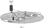
- the present disclosure is based on the 3GPP TSG RAN2 standard and an architecture between a base station and RSUs as shown in FIG. 1 .
- the architecture includes: the base station eNB, the RSU#1, the RSU#2, and a UE.
- An X2 interface exists between the RSU#1 and the RSU#2.
- An X2 interface exists between the RSU#1 and the base station eNB.
- An X2 interface exists between the RSU#2 and the base station eNB.
- the X2 interface is based on a backhaul line whose transmission characteristics are ideal.
- the technical solution disclosed by the embodiments of the present disclosure introduces a enabling-disabling control on the uplink signaling reduction mechanism by the base station, which is applicable to different scenarios in uplink resource configuration.
- the technical solution can solve the problem of signaling overhead caused by occupancy of macro network resources by location information reporting information of the UE such as a vehicle.
- Related description may be made with reference to the following embodiments.
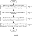
- FIG. 2 is a schematic flowchart of a method for processing uplink control plane signaling for V2X services according to Embodiment I of the present disclosure
- the method is applicable to a UE and includes the following steps.
- Step S110 the UE receives an uplink signaling reduction mechanism indicated by a base station in system information broadcast or other radio resource control (RRC) signaling.
- RRC radio resource control
- System information in the system information broadcast may include one master information block (MIB) and a plurality of system information blocks (SIBs).
- the SIBs are sent via the RRC signaling of a physical downlink shared channel (PDSCH).
- PDSCH physical downlink shared channel
- Step S120 the UE enables the uplink signaling reduction mechanism.
- Step S130 the UE selects, based on macro cell uplink resources, to camp on a macro cell or to access a small cell controlled by a plurality of road side units (RSUs).
- RSUs road side units
- the UE may change a mobility state management and a cell selection and handover function, and may select to access the small cell controlled by the RSUs.
- Step S140 the UE reports current location information through the X2 interface between the RSUs and through the X2 interface between the RSU and the base station.
- the UE selects to establish an RRC connection with the macro cell or the small cell controlled by the RSUs based on the mobility state maintenance and the cell selection and handover function.
- the UE when the base station indicates the uplink signaling reduction mechanism in the first RRC signaling or the second RRC signaling, the UE enables the uplink signaling reduction mechanism, selects, based on macro cell uplink resources, to camp on a macro cell or to access a small cell controlled by the RSUs, and reports the current location information through the X2 interfaces between the RSUs and through the X2 interfaces between the RSUs and the base station.
- the base station has an uplink signaling reduction mechanism.
- the UE By way of enabling-disabling the uplink signaling reduction mechanism by the base station, when the base station indicates the uplink signaling reduction mechanism in system information broadcast or other RRC signaling, the UE enables the uplink signaling reduction mechanism, such that the UE preferentially selects to camp on a macro cell or to access a small cell controlled by RSUs to save macro cell uplink resources. Further, the UE offloads the uplink report signaling from an air interface by way of a collaboration between the RSUs or a collaboration between the RSU and the base station during a handoff process, and transfers the report signaling to a RSU layer, which does not occupy macro network resources and reduces control plane signaling overheads, and thus the objective of increasing the overall utilization of radio resources is achieved.
- behaviors of the UE in an idle state and in a connected state are enhanced, such that the UE preferentially selects to camp on or access a small cell controlled by the RSUs to save macro cell uplink resources.
- the effect of the base station on introduction of the uplink signaling reduction mechanism may be reduced by planning a tracking area (TA) and configuring a tracking area identifier list (TAI list).
- TA tracking area
- TAI list tracking area identifier list
- the report signaling is transferred to the RSU layer, which does not occupy macro network resources.
- a corresponding solution of not losing location report information during the handoff process is also proposed.
- a cell reselection frequency may increase, and thus in the technical solution of the present disclosure, alternatively, the base station plans the TA of the base station, and the RSU plans the TA of the RSU, such that a tracking area update (TAU) of the macro cell and a TAU of the RSU are the same.
- TAU tracking area update
- the TA of the macro cell is different from that of the RSU, the TA of the base station and the TA of the RSU are configured into the TAI list of the UE.
- the UE in the idle state receives the TAI list allocated by the base station and the RSU to the UE.
- the TAU frequency of the UE may be reduced by reasonably planning the TA and by reasonably configuring the TAI list.
- the UE may report the current location information through the RSU, and may report the current location information of the UE to the base station through the X2 interface between the base station and the RSU, thereby avoiding occupancy of the uplink signaling of the base station.
- the handover frequency is small for the UE in a low mobility state, and thus less loss is caused in reporting the current location information.
- the UE handoffs between small cells controlled by the RSUs may be relatively frequent.
- the current location information is reported through the X2 interface between the first RSU and the second RSU when the UE switches between a road area covered by the first RSU and a road area covered by the second RSU.
- the UE may use a pre-configured resource pool or an abnormal resource pool, or use effective resources or resource pools between multiple RSUs to carry out V2X information transmission, which may still achieve the objective of saving the uplink report signaling overhead.
- the RSU has many types of antenna coverage modes such as omnidirectional coverage or linear coverage.
- the RSU selects an antenna direction in case of the linear coverage to obtain a strip-shaped road area with an expanded coverage range.
- the method further includes:
- the current location information saved in the UE may serve as a part of history information IE of the UE.
- the method further includes: reporting the current location information saved in the UE through the X2 interface between the first RSU and the second RSU before the connection between the UE and the first RSU is disconnected.
- the method further includes: broadcasting the current location information in a broadcast manner.
- the first RSU and the second RSU are each provided with a PC5 interface. After the current location information saved in the UE is received, the current location information is reported through the X2 interface between the RSU and the base station.
- the method further includes:
- the UE reports a cell identity (cell ID) of a previous RSU and/or a cell ID of a selected RSU to the base station through the X2 interface between the RSU and the base station when a global navigation satellite system (GNSS) of the UE or other positioning information is invalidated in a handoff process.
- GNSS global navigation satellite system
- the cell ID of the RSU herein also may be a small cell ID of the RSU.
- the cell ID of the previous RSU and/or the cell ID of the selected RSU are reported to the base station to serve as coarse-grained location information.
- the UE also may simultaneously report cell IDs of multiple RSUs, which can allow the base station to more accurately determine the location of the UE to support resource allocation.
- first and second in the embodiments of the present disclosure are merely intended for differentiating the same type of devices or apparatuses.
- the UE when the base station indicates the uplink signaling reduction mechanism in the system information broadcast or other RRC signaling, the UE enables the uplink signaling reduction mechanism, selects, based on macro cell uplink resources, to camp on a macro cell or to access a small cell controlled by the RSUs, and reports the current location information through the X2 interfaces between the RSUs and through the X2 interfaces between the RSU and the base station.
- the technical solution disclosed by the present disclosure introduces an uplink signaling reduction mechanism indicated by a base station.
- the UE By way of enabling-disabling control of the uplink signaling reduction mechanism by the base station, when the base station indicates the uplink signaling reduction mechanism in system information broadcast or other RRC signaling, the UE enables the uplink signaling reduction mechanism, such that the UE preferentially selects to camp on a macro cell or to access a small cell controlled by RSUs to save macro cell uplink resources.
- the UE offloads the uplink report signaling from an air interface by way of a collaboration between the RSUs and a collaboration between the RSU and the base station during a handoff process, and transfers the report signaling to a RSU layer, which does not occupy macro network resources and reduces control plane signaling overheads, and thus the objective of increasing the overall utilization of radio resources is achieved.
- Embodiment II of the present disclosure correspondingly discloses a device for processing uplink control plane signaling for V2X services, and a terminal applicable to the device for processing uplink control plane signaling for V2X services.
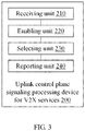
- the device 200 includes: a receiving unit 210, an enabling unit 220, a selecting unit 230, and a reporting unit 240.
- the receiving unit 210 is configured to receive an uplink signaling reduction mechanism indicated by the base station in system information broadcast or other radio resource control (RRC) signaling.
- RRC radio resource control
- the enabling unit 220 is configured to enable the uplink signaling reduction mechanism.
- the selecting unit 230 is configured to select, based on macro cell uplink resources, to camp on a macro cell or to access a small cell controlled by a plurality of road side units (RSUs).
- RSUs road side units
- the reporting unit 240 is configured to report current location information through X2 interfaces between the RSUs and through an X2 interface between the RSU and the base station.
- the base station eNB plans a tracking area (TA) of the base station eNB, and the RSU plans a TA of the RSU, such that a tracking area update (TAU) of the macro cell and a TAU of the RSU are the same.
- TA tracking area
- TAU tracking area update
- both the TA configured by the base station to the macro cell and the TA configured by the RSU to the RSU are configured into the TAI list of the UE.
- the receiving unit is configured to receive the TAI list of the UE configured by the base station and the RSU.
- the reporting unit when the UE is in a connected state, the reporting unit includes:
- a first reporting subunit configured to report the current location information through an X2 interface between a first RSU and a second RSU when the UE switches between a road area covered by the first RSU and a road area covered by the second RSU.
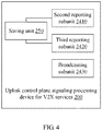
- the device 200 for processing uplink control plane signaling for V2X services further includes: a saving unit 250.
- the saving unit 250 is configured to save the current location information of the UE in the UE when the current location information of the UE is obtained under the first RSU.
- the reporting unit includes a second reporting subunit 2410, which is configured to report the current location information saved in the UE through the X2 interface between the first RSU and the second RSU when the UE establishes an RRC connection with the second RSU.
- the reporting unit includes a third reporting subunit 2420, which is configured to report the current location information saved in the UE through the X2 interface between the first RSU and the second RSU before the connection between the UE and the first RSU is disconnected.
- the reporting unit includes a broadcasting subunit 2430, which is configured to broadcast the current location information in a broadcast manner.
- the first RSU and the second RSU are each provided with a PC5 interface, and after the current location information saved in the UE is received, the current location information is reported through the X2 interface between the RSU and the base station eNB.
- the reporting unit further includes a fourth reporting subunit, which is configured to report a cell identity (cell ID) of a previous RSU and/or a cell ID of a selected RSU to the base station eNB through the X2 interface between the RSU and the base station eNB when a global navigation satellite system (GNSS) of the UE or other positioning information is invalidated in a handoff process.
- GNSS global navigation satellite system
- Embodiment III of the present disclosure further provides a non-transitory computer readable storage medium, which stores computer-executable instructions.
- the computer-executable instructions are used for executing the uplink control plane signaling processing method for V2X services according to any one of the above embodiments.
- Embodiment IV of the present disclosure discloses a schematic diagram of a hardware configuration of a user equipment. As shown in FIG. 5 , the user equipment includes:
- the user equipment may further include an input apparatus 330 and an output apparatus 340.
- the processor 310, the memory 320, the input apparatus 330 and the output apparatus 340 in the device may be connected by means of a bus or in other ways, in FIG. 5 connecting by means of a bus is taken as an example.
- the memory 320 may be configured to store software programs, computer executable programs and modules such as program instructions/modules (for example, the receiving unit 210, the enabling unit 220, the selecting unit 230, and the reporting unit 240 as shown in FIG. 3 ) corresponding to the method for processing uplink control plane signaling for V2X services in the embodiments of the present disclosure.
- the processor 310 may execute various function applications and data processing of a server, namely implement the method for processing uplink control plane signaling for V2X services in the foregoing method embodiments by running the software programs, instructions and modules stored in the memory 320.
- the memory 320 may include a program storage area and a data storage area.
- the program storage area may store an operating system, and application programs required for at least one function.
- the data storage area may store data created according to the use of a terminal device.
- the memory 320 may include a high speed random access memory, or may further include a non-volatile memory, for example, at least one magnetic disk storage device, a flash memory, or other non-volatile solid-state storage devices.
- the memory 320 may optionally include memories disposed remotely relative to the processor 320, and these remote memories may be connected to a terminal device via the network. Instances of the foregoing network includes but is not limited to the Internet, the Intranet, a local area network (LAN), a mobile communication network and a combination thereof.
- LAN local area network
- the input apparatus 330 may be configured to receive inputted numerical or character information to generate key signal inputs related to user settings and function control a terminal.
- the output apparatus 340 may include a display device such as a display screen, etc.
- the one or more modules are stored in the memory 320, and when they are executed by the one or more processors 310, the method for processing uplink control plane signaling for V2X services in the foregoing method embodiments is executed.
- the present disclosure provides a technical solution for processing uplink control plane signaling for V2X services.
- the UE preferentially selects to camp on a macro cell or to access a small cell controlled by RSUs to save macro cell uplink resources, and offloads the uplink report signaling from an air interface by way of the collaboration between the RSUs and the collaboration between the RSU and the base station, which reduces control plane signaling overheads, and thus the objective of increasing the overall utilization of radio resources is achieved.
- the UE by introducing a mechanism of indicating the uplink signaling reduction mechanism by the base station, the UE preferentially selects to camp on a macro cell or to access a small cell controlled by RSUs to save macro cell uplink resources, and offloads the uplink report signaling from an air interface by way of the collaboration between the RSUs and the collaboration between the RSU and the base station, which reduces control plane signaling overheads, and thus the overall utilization of radio resources is increased.
Landscapes
- Engineering & Computer Science (AREA)
- Computer Networks & Wireless Communication (AREA)
- Signal Processing (AREA)
- Mobile Radio Communication Systems (AREA)
Abstract
Description
- This application claims priority to Chinese Patent Application No.
201610029373.0 - The present disclosure relates to the field of communication technologies, for example, to an uplink control plane signaling processing method and apparatus for Vehicle to X (V2X) services, and a terminal.
- To achieve information exchange between vehicles and the outside world, a communication project of Vehicle to X (V2X) focused on studying transmission schemes of vehicle data based on the 3rd Generation Partnership Project (3GPP) communication protocol is approved to be established in 3GPP RAN#68. This project includes a Vehicle-to-Vehicle (V2V) communication project, a Vehicle to Pedestrian (V2P) communication project, and a Vehicle to Infrastructure (V2I) communication project, etc. V2V may be implemented through a Uu interface and a PC5 interface. A V2V communication mechanism based on PC5/D2D, the V2V may not occupy macro network radio bearer resources in a user plane data transmission process, and may naturally achieve spatial division multiplexing. Therefore, the V2V communication mechanism based on PC5/D2D is regarded as a LTE-based V2V mainstream technology.
- In the 3GPP TSG RANI #83 discussion, it was mentioned that a base station can schedule a sidelink (SL) transmission based on a current location of a user equipment (UE) such as a vehicle. In the process of scheduling by the base station based on the location of the user equipment, the UE continuously triggers a radio resource control (RRC) report message in order to let the base station learn the current location of the UE.
- However, excessive occupancy of signaling radio bearer (SRB) resources may be caused if the UE frequently reports its current location to the base station through the RRC messages. For example, excessive occupancy of resources will become more and more apparent as the number of UEs increases and the frequency of reporting increases. In fact, excessive macro network resources also may be occupied, which increases the signaling overhead of the entire control plane, and causes a decrease in the overall utilization of the radio resources.
- Based on the above problems, the present disclosure provides an uplink control plane signaling processing method and device for V2X services, and a terminal, which can solve the problem of increasing control plane signaling overheads caused by frequently reporting RRC messages to a base station, such that an overall utilization of radio resources is increased.
- In a first aspect, the present disclosure provides an uplink control plane signaling processing method for V2X services. The method is applicable to a terminal and includes:
- receiving an uplink signaling reduction mechanism indicated by a base station in first radio resource control (RRC) signaling or second RRC signaling, wherein the first RRC signaling is used for sending system information in system information broadcast;
- enabling the uplink signaling reduction mechanism;
- selecting, based on macro cell uplink resources, to camp on a macro cell or to access a small cell controlled by a plurality of road side units (RSUs); and
- reporting current location information through an X2 interface between the plurality of RSUs and through an X2 interface between the RSU and the base station.
- In this technical solution, alternatively, the method further includes:
selecting to establish an RRC connection with the macro cell or the small cell controlled by the RSUs based on a mobility state maintenance and a cell selection and handover function when the base station does not indicate the uplink signaling reduction mechanism in the first RRC signaling or the second RRC signaling. - In this technical solution, alternatively, when the UE is in an idle state, the base station plans a tracking area (TA) thereof, and each of the plurality of RSUs plans a TA thereof, such that a tracking area update (TAU) of the macro cell and a TAU of the plurality of RSUs are the same; and when a TA of the macro cell is different from TAs of the plurality of RSUs, the method further includes:
- receiving, by the UE, a tracking area identifier list (TAI list) configured by the base station and the RSUs to the UE; where the TAI list of the UE comprises the TA configured by the base station to the macro cell and the TAs configured by the RSUs to the RSUs, and the TA of the macro cell is different from the TAs of the RSUs.
- In this technical solution, alternatively, the method further includes:
reporting the current location information through an X2 interface between a first RSU and a second RSU when the UE is in a connected state and the UE switches between a road area covered by the first RSU and a road area covered by the second RSU. - In this technical solution, alternatively, the method further includes:
- saving the current location information of the UE in the UE when the current location information of the UE is obtained under the first RSU;
- reporting the current location information saved in the UE through the X2 interface between the first RSU and the second RSU when the UE establishes an RRC connection with the second RSU; or
- reporting the current location information saved in the UE through the X2 interface between the first RSU and the second RSU before the UE is disconnected from the first RSU; or
- broadcasting the current location information in a broadcast manner, wherein the first RSU and the second RSU are each configured with a PC5 interface, and after the current location information saved in the UE is received, the current location information is reported through the X2 interface between the RSU and the base station.
- In this technical solution, alternatively, the method further includes:
- reporting a cell identity (cell ID) of a previous RSU and/or a cell ID of a selected RSU to the base station through the X2 interface between the RSU and the base station when a global navigation satellite system (GNSS) of the UE or other positioning information is invalidated in a handoff process.
- In a second aspect, the present disclosure further provides an uplink control plane signaling processing device for V2X services. The device includes: a receiving unit, an enabling unit, a selecting unit, and a reporting unit.
- The receiving unit is configured to receive an uplink signaling reduction mechanism indicated in first radio resource control (RRC) signaling or second RRC signaling, wherein the first RRC signaling is used for sending system information in system information broadcast.
- The enabling unit is configured to enable the uplink signaling reduction mechanism.
- The selecting unit is configured to select, based on macro cell uplink resources, to camp on a macro cell or to access a small cell controlled by a plurality of road side units (RSUs).
- The reporting unit is configured to report current location information through an X2 interface between the plurality of RSUs and through an X2 interface between the RSU and the base station.
- In this technical solution, alternatively, when the UE is in an idle state, the base station plans a tracking area (TA) thereof, and each of the RSUs plans a TA thereof, such that a tracking area update (TAU) of the macro cell and a TAU of the plurality of RSUs are the same. When the TA of the macro cell is different from TAs of the RSUs ,
- the receiving unit is configured to receive a tracking area identifier list (TAI list) configured by the base station and the plurality of RSUs to the UE, the TAI list of the UE comprises the TA configured by the base station to the macro cell and TAs configured by the RSUs to the RSUs, and the TA of the macro cell is different from the TAs of the RSUs.
- In this technical solution, alternatively, when the UE is a UE in a connected state, the reporting unit includes:
- a first reporting subunit, configured to report the current location information through the X2 interface between a first RSU and a second RSU when the UE switches between a road area covered by the first RSU and a road area covered by the second RSU.
- In this technical solution, alternatively, the UE further includes:
- a saving unit, configured to save the current location information of the UE in the UE when the current location information of the UE is obtained under the first RSU.
- The reporting unit includes a second reporting subunit, configured to report the current location information saved in the UE through the X2 interface between the first RSU and the second RSU when the UE establishes an RRC connection with the second RSU.
- Alternatively,
the reporting unit includes a third reporting subunit, configured to the reporting unit comprises a third reporting subunit, configured to report the current location information saved in the UE through the X2 interface between the first RSU and the second RSU before the UE is disconnected from the first RSU. - Alternatively,
the reporting unit includes a broadcasting subunit, configured to broadcast the current location information in a broadcast manner, wherein the first RSU and the second RSU are each configured with a PC5 interface, and after the current location information saved in the UE is received, the current location information is reported through the X2 interface between the RSU and the base station. - In this technical solution, alternatively, the reporting unit includes:
a fourth reporting subunit, configured to report a cell identity (cell ID) of a previous RSU and/or a cell ID of a selected RSU to the base station through the X2 interface between the RSU and the base station when a global navigation satellite system (GNSS) of the UE or other positioning information is invalidated in a handoff process. - In a third aspect, an embodiment of the present disclosure also provides a user equipment. The user equipment includes one or more processors, memories, and one or more programs. The memories store the above uplink control plane signaling processing device for V2X services.
- In a fourth aspect, an embodiment of the present disclosure also provides a non-transitory computer readable storage medium, in which computer-executable instructions are stored. The computer-executable instructions may execute the uplink control plane signaling processing method for V2X services.
- According to the technical solution of processing uplink control plane signaling for V2X services disclosed by the embodiments of the present disclosure, when the base station indicates an uplink signaling reduction mechanism in the RRC signaling or the second RRC signaling, the UE enables the uplink signaling reduction mechanism. The UE selects, based on macro cell uplink resources, to camp on a macro cell or to access a small cell controlled by a plurality of RSUs. The UE reports the current location information through the X2 interface between the RSUs and through the X2 interface between the RSU and the base station. The technical solution of the present disclosure introduces an uplink signaling reduction mechanism indicated by a base station, by way of enabling-disabling control of the base station on the uplink signaling reduction mechanism, when the base station indicates the uplink signaling reduction mechanism in the first RRC signaling or the second RRC signaling, the UE enables the uplink signaling reduction mechanism, such that the UE preferentially selects to camp on a macro cell or to access a small cell controlled by RSUs to save macro cell uplink resources, and offloads the uplink report signaling from an air interface by way of a collaboration between the RSUs and a collaboration between the RSU and the base station during a handoff process, and transfers the report signaling to a road side unit (RSU) layer, which does not occupy macro network resources and reduces control plane signaling overheads, and thus the objective of increasing the overall utilization of radio resources is achieved.
-
-
FIG. 1 illustrates a schematic diagram of an architecture between a base station and RSUs according to an embodiment of the present disclosure; -
FIG. 2 illustrates a schematic flow diagram of an uplink control plane signaling processing method for Vehicle to V2X services according to Embodiment I of the present disclosure; -
FIG. 3 illustrates a schematic block diagram of an uplink control plane signalingprocessing device 200 for V2X services according to Embodiment II of the present disclosure; -
FIG. 4 illustrates a schematic partial block diagram of another uplink control plane signalingprocessing device 200 for V2X services according to Embodiment II of the present disclosure; and -
FIG. 5 illustrates a schematic diagram of a hardware configuration of a user equipment according to Embodiment IV of the present disclosure. - To more clearly understand the objectives, features and advantages of the present disclosure, related description of the present disclosure is made below with reference to the accompanying drawings and alternative embodiments. It is to be noted that the embodiments of the present disclosure and the features in the embodiments may be combined with each other on a non-conflict basis.
- Many details are set forth in the following description to fully understand the present disclosure. However, the present disclosure also may be implemented by using other manners other than the embodiments described herein. Therefore, the scope of protection of the present disclosure is not limited by the embodiments disclosed in the following.
- The present disclosure is based on the 3GPP TSG RAN2 standard and an architecture between a base station and RSUs as shown in
FIG. 1 . The architecture includes: the base station eNB, theRSU# 1, theRSU# 2, and a UE. An X2 interface exists between theRSU# 1 and theRSU# 2. An X2 interface exists between theRSU# 1 and the base station eNB. An X2 interface exists between theRSU# 2 and the base station eNB. The X2 interface is based on a backhaul line whose transmission characteristics are ideal. The technical solution disclosed by the embodiments of the present disclosure introduces a enabling-disabling control on the uplink signaling reduction mechanism by the base station, which is applicable to different scenarios in uplink resource configuration. By way of a collaboration between the RSUs and collaboration between the RSUs and the base station, the technical solution can solve the problem of signaling overhead caused by occupancy of macro network resources by location information reporting information of the UE such as a vehicle. Related description may be made with reference to the following embodiments. - As shown in
FIG. 2 , which is a schematic flowchart of a method for processing uplink control plane signaling for V2X services according to Embodiment I of the present disclosure, the method is applicable to a UE and includes the following steps. - In Step S110, the UE receives an uplink signaling reduction mechanism indicated by a base station in system information broadcast or other radio resource control (RRC) signaling.
- System information in the system information broadcast may include one master information block (MIB) and a plurality of system information blocks (SIBs). The SIBs are sent via the RRC signaling of a physical downlink shared channel (PDSCH).
- In Step S120, the UE enables the uplink signaling reduction mechanism.
- In Step S130, the UE selects, based on macro cell uplink resources, to camp on a macro cell or to access a small cell controlled by a plurality of road side units (RSUs).
- In Step S130, the UE may change a mobility state management and a cell selection and handover function, and may select to access the small cell controlled by the RSUs.
- In Step S140, the UE reports current location information through the X2 interface between the RSUs and through the X2 interface between the RSU and the base station.
- In this embodiment of the present disclosure, alternatively, when the base station does not indicate the uplink signaling reduction mechanism in the first RRC signaling or the second RRC signaling,
the UE selects to establish an RRC connection with the macro cell or the small cell controlled by the RSUs based on the mobility state maintenance and the cell selection and handover function. - According to the technical solution of processing control plane signaling disclosed by the embodiment of the present disclosure, when the base station indicates the uplink signaling reduction mechanism in the first RRC signaling or the second RRC signaling, the UE enables the uplink signaling reduction mechanism, selects, based on macro cell uplink resources, to camp on a macro cell or to access a small cell controlled by the RSUs, and reports the current location information through the X2 interfaces between the RSUs and through the X2 interfaces between the RSUs and the base station. According to the technical solution disclosed by the present disclosure, the base station has an uplink signaling reduction mechanism. By way of enabling-disabling the uplink signaling reduction mechanism by the base station, when the base station indicates the uplink signaling reduction mechanism in system information broadcast or other RRC signaling, the UE enables the uplink signaling reduction mechanism, such that the UE preferentially selects to camp on a macro cell or to access a small cell controlled by RSUs to save macro cell uplink resources. Further, the UE offloads the uplink report signaling from an air interface by way of a collaboration between the RSUs or a collaboration between the RSU and the base station during a handoff process, and transfers the report signaling to a RSU layer, which does not occupy macro network resources and reduces control plane signaling overheads, and thus the objective of increasing the overall utilization of radio resources is achieved.
- In this embodiment of the present disclosure, behaviors of the UE in an idle state and in a connected state are enhanced, such that the UE preferentially selects to camp on or access a small cell controlled by the RSUs to save macro cell uplink resources. For the UE in the idle state, the effect of the base station on introduction of the uplink signaling reduction mechanism may be reduced by planning a tracking area (TA) and configuring a tracking area identifier list (TAI list). For the UE in the connected state, the report signaling is transferred to the RSU layer, which does not occupy macro network resources. Moreover, a corresponding solution of not losing location report information during the handoff process is also proposed.
- When the UE is in an idle state, a cell reselection frequency may increase, and thus in the technical solution of the present disclosure, alternatively,
the base station plans the TA of the base station, and the RSU plans the TA of the RSU, such that a tracking area update (TAU) of the macro cell and a TAU of the RSU are the same. - When the TA of the macro cell is different from that of the RSU, the TA of the base station and the TA of the RSU are configured into the TAI list of the UE.
- At this moment, the UE in the idle state receives the TAI list allocated by the base station and the RSU to the UE. In this embodiment of the present disclosure, the TAU frequency of the UE may be reduced by reasonably planning the TA and by reasonably configuring the TAI list.
- When the UE is in the connected state, the UE may report the current location information through the RSU, and may report the current location information of the UE to the base station through the X2 interface between the base station and the RSU, thereby avoiding occupancy of the uplink signaling of the base station.
- When the UE is the UE in the connected state, the handover frequency is small for the UE in a low mobility state, and thus less loss is caused in reporting the current location information.
- For the UE in a medium mobility state or the UE in a high mobility state, the UE handoffs between small cells controlled by the RSUs may be relatively frequent. Thus, to alleviate the problem of frequent handoff, in this embodiment of the present disclosure, alternatively, the current location information is reported through the X2 interface between the first RSU and the second RSU when the UE switches between a road area covered by the first RSU and a road area covered by the second RSU.
- In this embodiment of the present disclosure, based on handoff between the road areas covered by the RSUs, on one hand, when the handoff occurs frequently, the caused signaling overhead exists between the UE and the RSU but does not depend on the base station; and on the other hand, the UE may use a pre-configured resource pool or an abnormal resource pool, or use effective resources or resource pools between multiple RSUs to carry out V2X information transmission, which may still achieve the objective of saving the uplink report signaling overhead.
- It is to be noted that the RSU has many types of antenna coverage modes such as omnidirectional coverage or linear coverage. The RSU selects an antenna direction in case of the linear coverage to obtain a strip-shaped road area with an expanded coverage range.
- When handoff is involved in the embodiment of the present disclosure, to ensure an uninterrupted transmission without occupying macro network radio resources when the UE reports the current location information during the handoff, in this embodiment of the present disclosure, alternatively, the method further includes:
- saving the current location information in the UE when the current location information of the UE is obtained under the first RSU; and
- reporting the current location information saved in the UE through the X2 interface between the first RSU and the second RSU when the UE establishes an RRC connection with the second RSU.
- It is to be noted that the current location information saved in the UE may serve as a part of history information IE of the UE.
- When handoff is involved in the embodiment of the present disclosure, to ensure an uninterrupted transmission without occupying macro network radio resources when the UE reports the current location information during the handoff, in this embodiment of the present disclosure, alternatively, the method further includes:
reporting the current location information saved in the UE through the X2 interface between the first RSU and the second RSU before the connection between the UE and the first RSU is disconnected. - When handoff is involved in the embodiment of the present disclosure, to ensure an uninterrupted transmission without occupying macro network radio resources when the UE reports the current location information during the handoff, in this embodiment of the present disclosure, alternatively, the method further includes:
broadcasting the current location information in a broadcast manner. - The first RSU and the second RSU are each provided with a PC5 interface. After the current location information saved in the UE is received, the current location information is reported through the X2 interface between the RSU and the base station.
- In any one of the above embodiments of the present disclosure, alternatively, the method further includes:
- The UE reports a cell identity (cell ID) of a previous RSU and/or a cell ID of a selected RSU to the base station through the X2 interface between the RSU and the base station when a global navigation satellite system (GNSS) of the UE or other positioning information is invalidated in a handoff process. The cell ID of the RSU herein also may be a small cell ID of the RSU.
- The cell ID of the previous RSU and/or the cell ID of the selected RSU are reported to the base station to serve as coarse-grained location information. The UE also may simultaneously report cell IDs of multiple RSUs, which can allow the base station to more accurately determine the location of the UE to support resource allocation.
- It is to be noted that the "first" and "second" in the embodiments of the present disclosure are merely intended for differentiating the same type of devices or apparatuses.
- According to the technical solution of processing control plane signaling disclosed by the embodiment of the present disclosure, when the base station indicates the uplink signaling reduction mechanism in the system information broadcast or other RRC signaling, the UE enables the uplink signaling reduction mechanism, selects, based on macro cell uplink resources, to camp on a macro cell or to access a small cell controlled by the RSUs, and reports the current location information through the X2 interfaces between the RSUs and through the X2 interfaces between the RSU and the base station. The technical solution disclosed by the present disclosure introduces an uplink signaling reduction mechanism indicated by a base station. By way of enabling-disabling control of the uplink signaling reduction mechanism by the base station, when the base station indicates the uplink signaling reduction mechanism in system information broadcast or other RRC signaling, the UE enables the uplink signaling reduction mechanism, such that the UE preferentially selects to camp on a macro cell or to access a small cell controlled by RSUs to save macro cell uplink resources. The UE offloads the uplink report signaling from an air interface by way of a collaboration between the RSUs and a collaboration between the RSU and the base station during a handoff process, and transfers the report signaling to a RSU layer, which does not occupy macro network resources and reduces control plane signaling overheads, and thus the objective of increasing the overall utilization of radio resources is achieved.
- Embodiment II of the present disclosure correspondingly discloses a device for processing uplink control plane signaling for V2X services, and a terminal applicable to the device for processing uplink control plane signaling for V2X services.
- A schematic block diagram of the
device 200 for processing uplink control plane signaling for V2X services according to the embodiment of the present disclosure is as shown inFIG. 3 . Thedevice 200 includes: a receivingunit 210, an enablingunit 220, a selectingunit 230, and areporting unit 240. - The receiving
unit 210 is configured to receive an uplink signaling reduction mechanism indicated by the base station in system information broadcast or other radio resource control (RRC) signaling. - The enabling
unit 220 is configured to enable the uplink signaling reduction mechanism. - The selecting
unit 230 is configured to select, based on macro cell uplink resources, to camp on a macro cell or to access a small cell controlled by a plurality of road side units (RSUs). - The
reporting unit 240 is configured to report current location information through X2 interfaces between the RSUs and through an X2 interface between the RSU and the base station. - In this embodiment of the present disclosure, alternatively, when the UE is in an idle state, the base station eNB plans a tracking area (TA) of the base station eNB, and the RSU plans a TA of the RSU, such that a tracking area update (TAU) of the macro cell and a TAU of the RSU are the same. When the TA of the macro cell is different from that of the RSU, both the TA configured by the base station to the macro cell and the TA configured by the RSU to the RSU are configured into the TAI list of the UE.
- The receiving unit is configured to receive the TAI list of the UE configured by the base station and the RSU.
- In this embodiment of the present disclosure, alternatively, when the UE is in a connected state, the reporting unit includes:
- a first reporting subunit, configured to report the current location information through an X2 interface between a first RSU and a second RSU when the UE switches between a road area covered by the first RSU and a road area covered by the second RSU.
- As shown in
FIG. 4 , in this embodiment of the present disclosure, alternatively, thedevice 200 for processing uplink control plane signaling for V2X services further includes: a savingunit 250. - The saving
unit 250 is configured to save the current location information of the UE in the UE when the current location information of the UE is obtained under the first RSU. - The reporting unit includes a second reporting subunit 2410, which is configured to report the current location information saved in the UE through the X2 interface between the first RSU and the second RSU when the UE establishes an RRC connection with the second RSU.
- The reporting unit includes a
third reporting subunit 2420, which is configured to report the current location information saved in the UE through the X2 interface between the first RSU and the second RSU before the connection between the UE and the first RSU is disconnected. - The reporting unit includes a
broadcasting subunit 2430, which is configured to broadcast the current location information in a broadcast manner. The first RSU and the second RSU are each provided with a PC5 interface, and after the current location information saved in the UE is received, the current location information is reported through the X2 interface between the RSU and the base station eNB. - In this embodiment of the present disclosure, alternatively, the reporting unit further includes a fourth reporting subunit, which is configured to report a cell identity (cell ID) of a previous RSU and/or a cell ID of a selected RSU to the base station eNB through the X2 interface between the RSU and the base station eNB when a global navigation satellite system (GNSS) of the UE or other positioning information is invalidated in a handoff process.
- Embodiment III of the present disclosure further provides a non-transitory computer readable storage medium, which stores computer-executable instructions. The computer-executable instructions are used for executing the uplink control plane signaling processing method for V2X services according to any one of the above embodiments.
- Embodiment IV of the present disclosure discloses a schematic diagram of a hardware configuration of a user equipment. As shown in
FIG. 5 , the user equipment includes: - one or
more processors 310, inFIG. 5 oneprocessor 310 being taken as an example; and - a
memory 320. - The user equipment may further include an
input apparatus 330 and anoutput apparatus 340. - The
processor 310, thememory 320, theinput apparatus 330 and theoutput apparatus 340 in the device may be connected by means of a bus or in other ways, inFIG. 5 connecting by means of a bus is taken as an example. - As a non-transitory computer readable storage medium, the
memory 320 may be configured to store software programs, computer executable programs and modules such as program instructions/modules (for example, the receivingunit 210, the enablingunit 220, the selectingunit 230, and thereporting unit 240 as shown inFIG. 3 ) corresponding to the method for processing uplink control plane signaling for V2X services in the embodiments of the present disclosure. Theprocessor 310 may execute various function applications and data processing of a server, namely implement the method for processing uplink control plane signaling for V2X services in the foregoing method embodiments by running the software programs, instructions and modules stored in thememory 320. - The
memory 320 may include a program storage area and a data storage area. The program storage area may store an operating system, and application programs required for at least one function. The data storage area may store data created according to the use of a terminal device. Moreover, thememory 320 may include a high speed random access memory, or may further include a non-volatile memory, for example, at least one magnetic disk storage device, a flash memory, or other non-volatile solid-state storage devices. In some embodiments, thememory 320 may optionally include memories disposed remotely relative to theprocessor 320, and these remote memories may be connected to a terminal device via the network. Instances of the foregoing network includes but is not limited to the Internet, the Intranet, a local area network (LAN), a mobile communication network and a combination thereof. - The
input apparatus 330 may be configured to receive inputted numerical or character information to generate key signal inputs related to user settings and function control a terminal. Theoutput apparatus 340 may include a display device such as a display screen, etc. - The one or more modules are stored in the
memory 320, and when they are executed by the one ormore processors 310, the method for processing uplink control plane signaling for V2X services in the foregoing method embodiments is executed. - The technical solution of the present disclosure is described in detail with reference to the accompanying drawings. The present disclosure provides a technical solution for processing uplink control plane signaling for V2X services. By introducing an indicating mechanism of an uplink signaling reduction at the base station, the UE preferentially selects to camp on a macro cell or to access a small cell controlled by RSUs to save macro cell uplink resources, and offloads the uplink report signaling from an air interface by way of the collaboration between the RSUs and the collaboration between the RSU and the base station, which reduces control plane signaling overheads, and thus the objective of increasing the overall utilization of radio resources is achieved.
- The above are merely preferred embodiments of the present disclosure and are not intended to limit the present disclosure. To those skilled in the art, the present disclosure may have various modifications and changes.
- According to the embodiments of the present disclosure, by introducing a mechanism of indicating the uplink signaling reduction mechanism by the base station, the UE preferentially selects to camp on a macro cell or to access a small cell controlled by RSUs to save macro cell uplink resources, and offloads the uplink report signaling from an air interface by way of the collaboration between the RSUs and the collaboration between the RSU and the base station, which reduces control plane signaling overheads, and thus the overall utilization of radio resources is increased.
Claims (13)
- An uplink control plane signaling processing method for Vehicle to X (V2X) services, the method being applicable to a User Equipment (UE) and comprising:receiving an uplink signaling reduction mechanism indicated by a base station in first radio resource control (RRC) signaling or second RRC signaling, wherein the first RRC signaling is used for sending system information in system information broadcast;enabling the uplink signaling reduction mechanism;selecting, based on macro cell uplink resources, to camp on a macro cell or to access a small cell controlled by a plurality of road side units (RSUs); andreporting current location information through an X2 interface between the plurality of RSUs and through an X2 interface between the RSU and the base station.
- The method according to claim 1, further comprising:selecting to establish an RRC connection with the macro cell or the small cell controlled by the RSUs based on a mobility state maintenance and a cell selection and handover function when the base station does not indicate the uplink signaling reduction mechanism in the first RRC signaling or the second RRC signaling.
- The method according to claim 1, wherein when the UE is in an idle state, the base station plans a tracking area (TA) thereof, and each of the plurality of RSUs plans a TA thereof, such that a tracking area update (TAU) of the macro cell and a TAU of the plurality of RSUs are the same; and when a TA of the macro cell is different from TAs of the plurality of RSUs, the method further comprises:receiving, by the UE, a tracking area identifier list (TAI list) configured by the base station and the RSUs to the UE;wherein the TAI list of the UE comprises the TA configured by the base station to the macro cell and the TAs configured by the RSUs to the RSUs, and the TA of the macro cell is different from the TAs of the RSUs.
- The method according to claim 1, further comprising:reporting the current location information through an X2 interface between a first RSU and a second RSU when the UE is in a connected state and the UE switches between a road area covered by the first RSU and a road area covered by the second RSU.
- The method according to claim 4, further comprising:saving the current location information of the UE in the UE when the current location information of the UE is obtained under the first RSU;reporting the current location information saved in the UE through the X2 interface between the first RSU and the second RSU when the UE establishes an RRC connection with the second RSU; orreporting the current location information saved in the UE through the X2 interface between the first RSU and the second RSU before the UE is disconnected from the first RSU; orbroadcasting the current location information in a broadcast manner, wherein the first RSU and the second RSU are each configured with a PC5 interface, and after the current location information saved in the UE is received, the current location information is reported through the X2 interface between the RSU and the base station.
- The method according to any one of claims 1-5, further comprising:reporting a cell identity (cell ID) of a previous RSU and/or a cell ID of a selected RSU to the base station through the X2 interface between the RSU and the base station when a global navigation satellite system (GNSS) of the UE or other positioning information is invalidated in a handoff process.
- An uplink control plane signaling processing device for Vehicle to X (V2X) services , the device being applicable to a User Equipment (UE) and comprising:a receiving unit, an enabling unit, a selecting unit, and a reporting unit, whereinthe receiving unit is configured to receive an uplink signaling reduction mechanism indicated in first radio resource control (RRC) signaling or second RRC signaling, wherein the first RRC signaling is used for sending system information in system information broadcast;the enabling unit is configured to enable the uplink signaling reduction mechanism;the selecting unit is configured to select, based on macro cell uplink resources, to camp on a macro cell or to access a small cell controlled by a plurality of road side units (RSUs); andthe reporting unit is configured to report current location information through an X2 interface between the plurality of RSUs and through an X2 interface between the RSU and the base station.
- The device according to claim 7, wherein when the UE is in an idle state, the base station plans a tracking area (TA) thereof, and each of the RSUs plans a TA thereof, such that a tracking area update (TAU) of the macro cell and a TAU of the plurality of RSUs are the same;
when the TA of the macro cell is different from TAs of the RSUs:the receiving unit is configured to receive a tracking area identifier list (TAI list) configured by the base station and the plurality of RSUs to the UE, the TAI list of the UE comprises the TA configured by the base station to the macro cell and TAs configured by the RSUs to the RSUs, and the TA of the macro cell is different from the TAs of the RSUs. - The device according to claim 7, wherein when the UE is in a connected state, the reporting unit comprises a first reporting subunit, wherein
the first reporting subunit is configured to report the current location information through the X2 interface between a first RSU and a second RSU when the UE switches between a road area covered by the first RSU and a road area covered by the second RSU. - The device according to claim 9, further comprising:a saving unit, configured to save the current location information of the UE in the UE when the current location information of the UE is obtained under the first RSU;the reporting unit comprises a second reporting subunit, configured to report the current location information saved in the UE through the X2 interface between the first RSU and the second RSU when the UE establishes an RRC connection with the second RSU;or,the reporting unit comprises a third reporting subunit, configured to report the current location information saved in the UE through the X2 interface between the first RSU and the second RSU before the UE is disconnected from the first RSU;or,the reporting unit comprises a broadcasting subunit, configured to broadcast the current location information in a broadcast manner, wherein the first RSU and the second RSU are each configured with a PC5 interface, and after the current location information saved in the UE is received, the current location information is reported through the X2 interface between the RSU and the base station.
- The device according to any one of claims 7-10, wherein the reporting unit comprises a fourth reporting subunit, wherein
the fourth reporting subunit is configured to report a cell identity (cell ID) of a previous RSU and/or a cell ID of a selected RSU to the base station through the X2 interface between the RSU and the base station when a global navigation satellite system (GNSS) of the UE or other positioning information is invalidated in a handoff process. - A terminal, comprising the uplink control plane signaling processing device for Vehicle to X (V2X) services according to any one of claims 7-11.
- A non-transitory computer readable storage medium, storing computer-executable instructions, wherein the computer-executable instructions are used for executing the uplink control plane signaling processing method for Vehicle to X (V2X) services according to any one of claims 1-7.
Applications Claiming Priority (2)
| Application Number | Priority Date | Filing Date | Title |
|---|---|---|---|
| CN201610029373.0A CN105704812B (en) | 2016-01-15 | 2016-01-15 | A kind of V2X business upload control plane signaling processing method, device and terminal |
| PCT/CN2016/092536 WO2017121098A1 (en) | 2016-01-15 | 2016-07-31 | Uplink control plane signaling processing method and device for v2x services, and terminal |
Publications (3)
| Publication Number | Publication Date |
|---|---|
| EP3404940A1 true EP3404940A1 (en) | 2018-11-21 |
| EP3404940A4 EP3404940A4 (en) | 2019-08-14 |
| EP3404940B1 EP3404940B1 (en) | 2020-11-18 |
Family
ID=56227497
Family Applications (1)
| Application Number | Title | Priority Date | Filing Date |
|---|---|---|---|
| EP16884652.5A Active EP3404940B1 (en) | 2016-01-15 | 2016-07-31 | Uplink control plane signaling processing method and device for v2x services, and terminal |
Country Status (4)
| Country | Link |
|---|---|
| US (1) | US10645550B2 (en) |
| EP (1) | EP3404940B1 (en) |
| CN (1) | CN105704812B (en) |
| WO (1) | WO2017121098A1 (en) |
Families Citing this family (10)
| Publication number | Priority date | Publication date | Assignee | Title |
|---|---|---|---|---|
| CN105704812B (en) * | 2016-01-15 | 2019-04-19 | 宇龙计算机通信科技(深圳)有限公司 | A kind of V2X business upload control plane signaling processing method, device and terminal |
| WO2017133000A1 (en) * | 2016-02-05 | 2017-08-10 | 广东欧珀移动通信有限公司 | Peer-to-peer data transmission method, apparatus, and system |
| CN109076429B (en) * | 2016-06-29 | 2020-10-27 | Oppo广东移动通信有限公司 | Communication method, forwarding device and terminal device |
| WO2018027799A1 (en) * | 2016-08-11 | 2018-02-15 | 富士通株式会社 | Information transmission method, device and communication system |
| CN107734480B (en) * | 2016-08-12 | 2020-01-17 | 普天信息技术有限公司 | A switching method and system |
| CN110838898B (en) | 2018-08-15 | 2021-01-26 | 上海朗帛通信技术有限公司 | A method and apparatus used in a wireless communication node |
| CN110536430B (en) * | 2018-09-05 | 2023-04-07 | 中兴通讯股份有限公司 | Communication and resource allocation method, device, base station, terminal and storage medium |
| WO2020258632A1 (en) * | 2019-06-26 | 2020-12-30 | Oppo广东移动通信有限公司 | Wireless communication method and terminal device |
| KR20230144011A (en) * | 2021-02-10 | 2023-10-13 | 퀄컴 인코포레이티드 | Improvements to network coding for handover |
| WO2023272415A1 (en) * | 2021-06-28 | 2023-01-05 | Qualcomm Incorporated | Location-based service access for vehicle-to-everything (v2x) systems |
Family Cites Families (13)
| Publication number | Priority date | Publication date | Assignee | Title |
|---|---|---|---|---|
| CN102209345B (en) * | 2010-03-29 | 2016-05-25 | 中兴通讯股份有限公司 | A kind of method of wireless communication system and reporting drive test result thereof |
| CN103428727B (en) * | 2012-05-14 | 2018-07-20 | 中兴通讯股份有限公司 | The detection method and system of a kind of UE close to micro-base station |
| WO2014015470A1 (en) * | 2012-07-23 | 2014-01-30 | Renesas Mobile Corporation | Vehicle gateway access in cellular network for vehicle communications |
| CN103686823B (en) * | 2012-09-06 | 2017-12-05 | 华为技术有限公司 | The method and apparatus of measurement |
| CN103200526B (en) * | 2013-03-27 | 2015-09-23 | 山东大学 | A kind of method of the vehicular ad hoc network route based on roadside base station |
| US9801044B2 (en) * | 2014-05-13 | 2017-10-24 | Samsung Electronics Co., Ltd. | Apparatus and method for accessing wireless network |
| CN104637328B (en) * | 2015-01-07 | 2016-08-17 | 浙江大学 | Distributed real-time navigation method based on RSU in a kind of vehicle self-organizing network |
| CN104836673B (en) * | 2015-01-20 | 2019-01-18 | 北京大学 | Simplify cooperation broadcasting method in a kind of V2V secure communication based on TD-LTE |
| US10531418B2 (en) * | 2015-03-12 | 2020-01-07 | Lg Electronics Inc. | Communication method of user equipment installed in vehicle in V2X communication system, and user equipment |
| US10505783B2 (en) * | 2015-06-30 | 2019-12-10 | Lg Electronics Inc. | Terminal and V2X communication method thereof in V2X communication system |
| WO2017030423A1 (en) * | 2015-08-19 | 2017-02-23 | 엘지전자 주식회사 | V2x operation method performed by terminal in wireless communication system and terminal using same method |
| US10524099B2 (en) * | 2015-10-30 | 2019-12-31 | Lg Electronics Inc. | Method and apparatus for supporting bearer type for V2X communication in wireless communication system |
| CN105704812B (en) | 2016-01-15 | 2019-04-19 | 宇龙计算机通信科技(深圳)有限公司 | A kind of V2X business upload control plane signaling processing method, device and terminal |
-
2016
- 2016-01-15 CN CN201610029373.0A patent/CN105704812B/en active Active
- 2016-07-31 WO PCT/CN2016/092536 patent/WO2017121098A1/en not_active Ceased
- 2016-07-31 US US16/070,266 patent/US10645550B2/en active Active
- 2016-07-31 EP EP16884652.5A patent/EP3404940B1/en active Active
Also Published As
| Publication number | Publication date |
|---|---|
| WO2017121098A1 (en) | 2017-07-20 |
| US20190014523A1 (en) | 2019-01-10 |
| EP3404940B1 (en) | 2020-11-18 |
| CN105704812A (en) | 2016-06-22 |
| EP3404940A4 (en) | 2019-08-14 |
| US10645550B2 (en) | 2020-05-05 |
| CN105704812B (en) | 2019-04-19 |
Similar Documents
| Publication | Publication Date | Title |
|---|---|---|
| US10645550B2 (en) | Uplink control plane signaling processing method and device for V2X services, and terminal | |
| EP4122265B1 (en) | Nr sidelink assistance information messages | |
| EP3301985B1 (en) | Radio resource scheduling method, device and system | |
| US10674380B2 (en) | On-demand system information for wireless terminal in connected state | |
| EP3439394B1 (en) | Resource configuration methods and devices | |
| JP6509353B2 (en) | User apparatus, base station, communication method and notification method | |
| KR102200982B1 (en) | UE state switching method and apparatus | |
| EP3864908B1 (en) | Method and apparatus for synchronization reference source selection | |
| US12200605B2 (en) | Mobile telecommunications system entity for transmitting system information in a 5G network | |
| CN113163456B (en) | Communication method and device | |
| US12464515B2 (en) | Method and apparatus of group-based resource allocation | |
| US20140321355A1 (en) | Relay using device-to-device communication in the infrastructure-based communication system | |
| US9596689B2 (en) | Radio resource allocation for D2D communications | |
| CN114097277B (en) | Active switching of V2X communication from SIDELINK connection to cell connection | |
| CN109923895B (en) | Network node and method for establishing neighbor node relation in network node | |
| EP3657896A1 (en) | Device, base station, and control methods thereof in wireless communication system | |
| JP2018514962A (en) | System and method for mobility tracking of user equipment | |
| US11259231B2 (en) | Relay determining method and apparatus | |
| US11432361B2 (en) | Method and apparatus for configuring UE information, base station and core network device | |
| WO2018127056A1 (en) | System information sending and processing method and apparatus | |
| CN119071919A (en) | Data transmission method, device, communication equipment and storage medium | |
| CN120111598A (en) | Communication method, device and storage medium | |
| US10548064B1 (en) | Controlling relay broadcast of system messaging based on donor base station air interface utilization | |
| CN113630128A (en) | Frequency processing method and device, terminal equipment and storage medium | |
| KR101628627B1 (en) | System and metheod for transmitting vechcle terminal safty data |
Legal Events
| Date | Code | Title | Description |
|---|---|---|---|
| STAA | Information on the status of an ep patent application or granted ep patent |
Free format text: STATUS: THE INTERNATIONAL PUBLICATION HAS BEEN MADE |
|
| PUAI | Public reference made under article 153(3) epc to a published international application that has entered the european phase |
Free format text: ORIGINAL CODE: 0009012 |
|
| STAA | Information on the status of an ep patent application or granted ep patent |
Free format text: STATUS: REQUEST FOR EXAMINATION WAS MADE |
|
| 17P | Request for examination filed |
Effective date: 20180727 |
|
| AK | Designated contracting states |
Kind code of ref document: A1 Designated state(s): AL AT BE BG CH CY CZ DE DK EE ES FI FR GB GR HR HU IE IS IT LI LT LU LV MC MK MT NL NO PL PT RO RS SE SI SK SM TR |
|
| AX | Request for extension of the european patent |
Extension state: BA ME |
|
| RIC1 | Information provided on ipc code assigned before grant |
Ipc: H04W 4/04 20090101AFI20170808BHEP |
|
| DAV | Request for validation of the european patent (deleted) | ||
| DAX | Request for extension of the european patent (deleted) | ||
| REG | Reference to a national code |
Ref country code: DE Ref legal event code: R079 Ref document number: 602016048348 Country of ref document: DE Free format text: PREVIOUS MAIN CLASS: H04W0004040000 Ipc: H04W0004400000 |
|
| A4 | Supplementary search report drawn up and despatched |
Effective date: 20190715 |
|
| RIC1 | Information provided on ipc code assigned before grant |
Ipc: H04W 4/40 20180101AFI20190709BHEP Ipc: H04W 72/12 20090101ALI20190709BHEP Ipc: H04W 4/029 20180101ALI20190709BHEP Ipc: H04W 76/10 20180101ALI20190709BHEP Ipc: H04W 36/32 20090101ALI20190709BHEP Ipc: H04W 4/20 20180101ALI20190709BHEP |
|
| GRAP | Despatch of communication of intention to grant a patent |
Free format text: ORIGINAL CODE: EPIDOSNIGR1 |
|
| STAA | Information on the status of an ep patent application or granted ep patent |
Free format text: STATUS: GRANT OF PATENT IS INTENDED |
|
| INTG | Intention to grant announced |
Effective date: 20200629 |
|
| GRAS | Grant fee paid |
Free format text: ORIGINAL CODE: EPIDOSNIGR3 |
|
| GRAA | (expected) grant |
Free format text: ORIGINAL CODE: 0009210 |
|
| STAA | Information on the status of an ep patent application or granted ep patent |
Free format text: STATUS: THE PATENT HAS BEEN GRANTED |
|
| AK | Designated contracting states |
Kind code of ref document: B1 Designated state(s): AL AT BE BG CH CY CZ DE DK EE ES FI FR GB GR HR HU IE IS IT LI LT LU LV MC MK MT NL NO PL PT RO RS SE SI SK SM TR |
|
| REG | Reference to a national code |
Ref country code: GB Ref legal event code: FG4D |
|
| REG | Reference to a national code |
Ref country code: CH Ref legal event code: EP |
|
| REG | Reference to a national code |
Ref country code: DE Ref legal event code: R096 Ref document number: 602016048348 Country of ref document: DE |
|
| REG | Reference to a national code |
Ref country code: IE Ref legal event code: FG4D |
|
| REG | Reference to a national code |
Ref country code: AT Ref legal event code: REF Ref document number: 1337067 Country of ref document: AT Kind code of ref document: T Effective date: 20201215 |
|
| REG | Reference to a national code |
Ref country code: AT Ref legal event code: MK05 Ref document number: 1337067 Country of ref document: AT Kind code of ref document: T Effective date: 20201118 |
|
| REG | Reference to a national code |
Ref country code: NL Ref legal event code: MP Effective date: 20201118 |
|
| PG25 | Lapsed in a contracting state [announced via postgrant information from national office to epo] |
Ref country code: GR Free format text: LAPSE BECAUSE OF FAILURE TO SUBMIT A TRANSLATION OF THE DESCRIPTION OR TO PAY THE FEE WITHIN THE PRESCRIBED TIME-LIMIT Effective date: 20210219 Ref country code: FI Free format text: LAPSE BECAUSE OF FAILURE TO SUBMIT A TRANSLATION OF THE DESCRIPTION OR TO PAY THE FEE WITHIN THE PRESCRIBED TIME-LIMIT Effective date: 20201118 Ref country code: PT Free format text: LAPSE BECAUSE OF FAILURE TO SUBMIT A TRANSLATION OF THE DESCRIPTION OR TO PAY THE FEE WITHIN THE PRESCRIBED TIME-LIMIT Effective date: 20210318 Ref country code: RS Free format text: LAPSE BECAUSE OF FAILURE TO SUBMIT A TRANSLATION OF THE DESCRIPTION OR TO PAY THE FEE WITHIN THE PRESCRIBED TIME-LIMIT Effective date: 20201118 Ref country code: NO Free format text: LAPSE BECAUSE OF FAILURE TO SUBMIT A TRANSLATION OF THE DESCRIPTION OR TO PAY THE FEE WITHIN THE PRESCRIBED TIME-LIMIT Effective date: 20210218 |
|
| PG25 | Lapsed in a contracting state [announced via postgrant information from national office to epo] |
Ref country code: SE Free format text: LAPSE BECAUSE OF FAILURE TO SUBMIT A TRANSLATION OF THE DESCRIPTION OR TO PAY THE FEE WITHIN THE PRESCRIBED TIME-LIMIT Effective date: 20201118 Ref country code: BG Free format text: LAPSE BECAUSE OF FAILURE TO SUBMIT A TRANSLATION OF THE DESCRIPTION OR TO PAY THE FEE WITHIN THE PRESCRIBED TIME-LIMIT Effective date: 20210218 Ref country code: LV Free format text: LAPSE BECAUSE OF FAILURE TO SUBMIT A TRANSLATION OF THE DESCRIPTION OR TO PAY THE FEE WITHIN THE PRESCRIBED TIME-LIMIT Effective date: 20201118 Ref country code: PL Free format text: LAPSE BECAUSE OF FAILURE TO SUBMIT A TRANSLATION OF THE DESCRIPTION OR TO PAY THE FEE WITHIN THE PRESCRIBED TIME-LIMIT Effective date: 20201118 Ref country code: IS Free format text: LAPSE BECAUSE OF FAILURE TO SUBMIT A TRANSLATION OF THE DESCRIPTION OR TO PAY THE FEE WITHIN THE PRESCRIBED TIME-LIMIT Effective date: 20210318 Ref country code: AT Free format text: LAPSE BECAUSE OF FAILURE TO SUBMIT A TRANSLATION OF THE DESCRIPTION OR TO PAY THE FEE WITHIN THE PRESCRIBED TIME-LIMIT Effective date: 20201118 |
|
| REG | Reference to a national code |
Ref country code: LT Ref legal event code: MG9D |
|
| PG25 | Lapsed in a contracting state [announced via postgrant information from national office to epo] |
Ref country code: HR Free format text: LAPSE BECAUSE OF FAILURE TO SUBMIT A TRANSLATION OF THE DESCRIPTION OR TO PAY THE FEE WITHIN THE PRESCRIBED TIME-LIMIT Effective date: 20201118 |
|
| PG25 | Lapsed in a contracting state [announced via postgrant information from national office to epo] |
Ref country code: SK Free format text: LAPSE BECAUSE OF FAILURE TO SUBMIT A TRANSLATION OF THE DESCRIPTION OR TO PAY THE FEE WITHIN THE PRESCRIBED TIME-LIMIT Effective date: 20201118 Ref country code: RO Free format text: LAPSE BECAUSE OF FAILURE TO SUBMIT A TRANSLATION OF THE DESCRIPTION OR TO PAY THE FEE WITHIN THE PRESCRIBED TIME-LIMIT Effective date: 20201118 Ref country code: EE Free format text: LAPSE BECAUSE OF FAILURE TO SUBMIT A TRANSLATION OF THE DESCRIPTION OR TO PAY THE FEE WITHIN THE PRESCRIBED TIME-LIMIT Effective date: 20201118 Ref country code: CZ Free format text: LAPSE BECAUSE OF FAILURE TO SUBMIT A TRANSLATION OF THE DESCRIPTION OR TO PAY THE FEE WITHIN THE PRESCRIBED TIME-LIMIT Effective date: 20201118 Ref country code: SM Free format text: LAPSE BECAUSE OF FAILURE TO SUBMIT A TRANSLATION OF THE DESCRIPTION OR TO PAY THE FEE WITHIN THE PRESCRIBED TIME-LIMIT Effective date: 20201118 Ref country code: LT Free format text: LAPSE BECAUSE OF FAILURE TO SUBMIT A TRANSLATION OF THE DESCRIPTION OR TO PAY THE FEE WITHIN THE PRESCRIBED TIME-LIMIT Effective date: 20201118 |
|
| REG | Reference to a national code |
Ref country code: DE Ref legal event code: R097 Ref document number: 602016048348 Country of ref document: DE |
|
| PG25 | Lapsed in a contracting state [announced via postgrant information from national office to epo] |
Ref country code: DK Free format text: LAPSE BECAUSE OF FAILURE TO SUBMIT A TRANSLATION OF THE DESCRIPTION OR TO PAY THE FEE WITHIN THE PRESCRIBED TIME-LIMIT Effective date: 20201118 |
|
| PLBE | No opposition filed within time limit |
Free format text: ORIGINAL CODE: 0009261 |
|
| STAA | Information on the status of an ep patent application or granted ep patent |
Free format text: STATUS: NO OPPOSITION FILED WITHIN TIME LIMIT |
|
| 26N | No opposition filed |
Effective date: 20210819 |
|
| PG25 | Lapsed in a contracting state [announced via postgrant information from national office to epo] |
Ref country code: IT Free format text: LAPSE BECAUSE OF FAILURE TO SUBMIT A TRANSLATION OF THE DESCRIPTION OR TO PAY THE FEE WITHIN THE PRESCRIBED TIME-LIMIT Effective date: 20201118 Ref country code: AL Free format text: LAPSE BECAUSE OF FAILURE TO SUBMIT A TRANSLATION OF THE DESCRIPTION OR TO PAY THE FEE WITHIN THE PRESCRIBED TIME-LIMIT Effective date: 20201118 Ref country code: NL Free format text: LAPSE BECAUSE OF FAILURE TO SUBMIT A TRANSLATION OF THE DESCRIPTION OR TO PAY THE FEE WITHIN THE PRESCRIBED TIME-LIMIT Effective date: 20201118 |
|
| PG25 | Lapsed in a contracting state [announced via postgrant information from national office to epo] |
Ref country code: SI Free format text: LAPSE BECAUSE OF FAILURE TO SUBMIT A TRANSLATION OF THE DESCRIPTION OR TO PAY THE FEE WITHIN THE PRESCRIBED TIME-LIMIT Effective date: 20201118 |
|
| PG25 | Lapsed in a contracting state [announced via postgrant information from national office to epo] |
Ref country code: ES Free format text: LAPSE BECAUSE OF FAILURE TO SUBMIT A TRANSLATION OF THE DESCRIPTION OR TO PAY THE FEE WITHIN THE PRESCRIBED TIME-LIMIT Effective date: 20201118 |
|
| REG | Reference to a national code |
Ref country code: CH Ref legal event code: PL |
|
| PG25 | Lapsed in a contracting state [announced via postgrant information from national office to epo] |
Ref country code: MC Free format text: LAPSE BECAUSE OF FAILURE TO SUBMIT A TRANSLATION OF THE DESCRIPTION OR TO PAY THE FEE WITHIN THE PRESCRIBED TIME-LIMIT Effective date: 20201118 |
|
| REG | Reference to a national code |
Ref country code: BE Ref legal event code: MM Effective date: 20210731 |
|
| PG25 | Lapsed in a contracting state [announced via postgrant information from national office to epo] |
Ref country code: LI Free format text: LAPSE BECAUSE OF NON-PAYMENT OF DUE FEES Effective date: 20210731 Ref country code: CH Free format text: LAPSE BECAUSE OF NON-PAYMENT OF DUE FEES Effective date: 20210731 |
|
| PG25 | Lapsed in a contracting state [announced via postgrant information from national office to epo] |
Ref country code: IS Free format text: LAPSE BECAUSE OF FAILURE TO SUBMIT A TRANSLATION OF THE DESCRIPTION OR TO PAY THE FEE WITHIN THE PRESCRIBED TIME-LIMIT Effective date: 20210318 Ref country code: LU Free format text: LAPSE BECAUSE OF NON-PAYMENT OF DUE FEES Effective date: 20210731 |
|
| PG25 | Lapsed in a contracting state [announced via postgrant information from national office to epo] |
Ref country code: IE Free format text: LAPSE BECAUSE OF NON-PAYMENT OF DUE FEES Effective date: 20210731 Ref country code: BE Free format text: LAPSE BECAUSE OF NON-PAYMENT OF DUE FEES Effective date: 20210731 |
|
| PG25 | Lapsed in a contracting state [announced via postgrant information from national office to epo] |
Ref country code: CY Free format text: LAPSE BECAUSE OF FAILURE TO SUBMIT A TRANSLATION OF THE DESCRIPTION OR TO PAY THE FEE WITHIN THE PRESCRIBED TIME-LIMIT Effective date: 20201118 |
|
| PG25 | Lapsed in a contracting state [announced via postgrant information from national office to epo] |
Ref country code: HU Free format text: LAPSE BECAUSE OF FAILURE TO SUBMIT A TRANSLATION OF THE DESCRIPTION OR TO PAY THE FEE WITHIN THE PRESCRIBED TIME-LIMIT; INVALID AB INITIO Effective date: 20160731 |
|
| PG25 | Lapsed in a contracting state [announced via postgrant information from national office to epo] |
Ref country code: MK Free format text: LAPSE BECAUSE OF FAILURE TO SUBMIT A TRANSLATION OF THE DESCRIPTION OR TO PAY THE FEE WITHIN THE PRESCRIBED TIME-LIMIT Effective date: 20201118 |
|
| PG25 | Lapsed in a contracting state [announced via postgrant information from national office to epo] |
Ref country code: TR Free format text: LAPSE BECAUSE OF FAILURE TO SUBMIT A TRANSLATION OF THE DESCRIPTION OR TO PAY THE FEE WITHIN THE PRESCRIBED TIME-LIMIT Effective date: 20201118 |
|
| PG25 | Lapsed in a contracting state [announced via postgrant information from national office to epo] |
Ref country code: MT Free format text: LAPSE BECAUSE OF FAILURE TO SUBMIT A TRANSLATION OF THE DESCRIPTION OR TO PAY THE FEE WITHIN THE PRESCRIBED TIME-LIMIT Effective date: 20201118 |
|
| PGFP | Annual fee paid to national office [announced via postgrant information from national office to epo] |
Ref country code: DE Payment date: 20250711 Year of fee payment: 10 |
|
| PGFP | Annual fee paid to national office [announced via postgrant information from national office to epo] |
Ref country code: GB Payment date: 20250723 Year of fee payment: 10 |
|
| PGFP | Annual fee paid to national office [announced via postgrant information from national office to epo] |
Ref country code: FR Payment date: 20250730 Year of fee payment: 10 |