EP3404795A1 - Charger for charging battery pack of electric power tool - Google Patents
Charger for charging battery pack of electric power tool Download PDFInfo
- Publication number
- EP3404795A1 EP3404795A1 EP18170673.0A EP18170673A EP3404795A1 EP 3404795 A1 EP3404795 A1 EP 3404795A1 EP 18170673 A EP18170673 A EP 18170673A EP 3404795 A1 EP3404795 A1 EP 3404795A1
- Authority
- EP
- European Patent Office
- Prior art keywords
- housing
- charger
- exhaust port
- wall
- intake port
- Prior art date
- Legal status (The legal status is an assumption and is not a legal conclusion. Google has not performed a legal analysis and makes no representation as to the accuracy of the status listed.)
- Granted
Links
Images




Classifications
-
- H—ELECTRICITY
- H02—GENERATION; CONVERSION OR DISTRIBUTION OF ELECTRIC POWER
- H02J—ELECTRIC POWER NETWORKS; CIRCUIT ARRANGEMENTS OR SYSTEMS FOR SUPPLYING OR DISTRIBUTING ELECTRIC POWER; SYSTEMS FOR STORING ELECTRIC ENERGY
- H02J7/00—Circuit arrangements for charging or discharging batteries or for supplying loads from batteries
- H02J7/70—Circuit arrangements for charging or discharging batteries or for supplying loads from batteries characterised by the mechanical construction
-
- H—ELECTRICITY
- H01—ELECTRIC ELEMENTS
- H01M—PROCESSES OR MEANS, e.g. BATTERIES, FOR THE DIRECT CONVERSION OF CHEMICAL ENERGY INTO ELECTRICAL ENERGY
- H01M10/00—Secondary cells; Manufacture thereof
- H01M10/42—Methods or arrangements for servicing or maintenance of secondary cells or secondary half-cells
- H01M10/44—Methods for charging or discharging
-
- H—ELECTRICITY
- H02—GENERATION; CONVERSION OR DISTRIBUTION OF ELECTRIC POWER
- H02J—ELECTRIC POWER NETWORKS; CIRCUIT ARRANGEMENTS OR SYSTEMS FOR SUPPLYING OR DISTRIBUTING ELECTRIC POWER; SYSTEMS FOR STORING ELECTRIC ENERGY
- H02J7/00—Circuit arrangements for charging or discharging batteries or for supplying loads from batteries
- H02J7/50—Circuit arrangements for charging or discharging batteries or for supplying loads from batteries acting upon multiple batteries simultaneously or sequentially
-
- H—ELECTRICITY
- H02—GENERATION; CONVERSION OR DISTRIBUTION OF ELECTRIC POWER
- H02J—ELECTRIC POWER NETWORKS; CIRCUIT ARRANGEMENTS OR SYSTEMS FOR SUPPLYING OR DISTRIBUTING ELECTRIC POWER; SYSTEMS FOR STORING ELECTRIC ENERGY
- H02J7/00—Circuit arrangements for charging or discharging batteries or for supplying loads from batteries
- H02J7/70—Circuit arrangements for charging or discharging batteries or for supplying loads from batteries characterised by the mechanical construction
- H02J7/731—Circuit arrangements for charging or discharging batteries or for supplying loads from batteries characterised by the mechanical construction specially adapted for holding portable devices containing batteries
-
- H—ELECTRICITY
- H05—ELECTRIC TECHNIQUES NOT OTHERWISE PROVIDED FOR
- H05K—PRINTED CIRCUITS; CASINGS OR CONSTRUCTIONAL DETAILS OF ELECTRIC APPARATUS; MANUFACTURE OF ASSEMBLAGES OF ELECTRICAL COMPONENTS
- H05K7/00—Constructional details common to different types of electric apparatus
- H05K7/20—Modifications to facilitate cooling, ventilating, or heating
- H05K7/2089—Modifications to facilitate cooling, ventilating, or heating for power electronics, e.g. for inverters for controlling motor
- H05K7/20909—Forced ventilation, e.g. on heat dissipaters coupled to components
-
- B—PERFORMING OPERATIONS; TRANSPORTING
- B25—HAND TOOLS; PORTABLE POWER-DRIVEN TOOLS; MANIPULATORS
- B25F—COMBINATION OR MULTI-PURPOSE TOOLS NOT OTHERWISE PROVIDED FOR; DETAILS OR COMPONENTS OF PORTABLE POWER-DRIVEN TOOLS NOT PARTICULARLY RELATED TO THE OPERATIONS PERFORMED AND NOT OTHERWISE PROVIDED FOR
- B25F5/00—Details or components of portable power-driven tools not particularly related to the operations performed and not otherwise provided for
- B25F5/02—Construction of casings, bodies or handles
-
- H—ELECTRICITY
- H01—ELECTRIC ELEMENTS
- H01M—PROCESSES OR MEANS, e.g. BATTERIES, FOR THE DIRECT CONVERSION OF CHEMICAL ENERGY INTO ELECTRICAL ENERGY
- H01M2220/00—Batteries for particular applications
- H01M2220/30—Batteries in portable systems, e.g. mobile phone, laptop
-
- Y—GENERAL TAGGING OF NEW TECHNOLOGICAL DEVELOPMENTS; GENERAL TAGGING OF CROSS-SECTIONAL TECHNOLOGIES SPANNING OVER SEVERAL SECTIONS OF THE IPC; TECHNICAL SUBJECTS COVERED BY FORMER USPC CROSS-REFERENCE ART COLLECTIONS [XRACs] AND DIGESTS
- Y02—TECHNOLOGIES OR APPLICATIONS FOR MITIGATION OR ADAPTATION AGAINST CLIMATE CHANGE
- Y02E—REDUCTION OF GREENHOUSE GAS [GHG] EMISSIONS, RELATED TO ENERGY GENERATION, TRANSMISSION OR DISTRIBUTION
- Y02E60/00—Enabling technologies; Technologies with a potential or indirect contribution to GHG emissions mitigation
- Y02E60/10—Energy storage using batteries
Definitions
- a technology disclosed in the present disclosure relates to a charger for charging a battery pack of an electric power tool.
- Japanese Patent Application Publication No. 2016-149841 describes a charger for charging a battery pack of an electric power tool.
- This charger includes a housing which includes an intake port and an exhaust port, a battery interface which is provided on the housing, a charging circuit which supplies charging power to a battery pack attached to the battery interface and a blower which introduces air into the housing through the intake port and exhausts air to outside of the housing through the exhaust port.
- a blower which introduces air into the housing through the intake port and exhausts air to outside of the housing through the exhaust port.
- a conventional charger is designed as a desktop device and is normally installed on a desk or a rack.
- a limited space on the desk or the rack may be occupied by the charger.
- the charger is mountable on a wall, the charger is mounted on the wall, and thus the charger can be removed from the desk or the rack.
- a posture of the charger is significantly changed (for example, by an angle of 90 degrees).
- a flow of air within a housing may be changed. Since the conventional charger is designed as a desktop device, it is likely that in the posture where the charger is mounted on the wall, an interior of the housing cannot be sufficiently ventilated.
- the present disclosure provides a technology that allows sufficient ventilation in an interior of a housing in a charger which is mountable on a wall.
- a charger configured to charge a battery pack of an electric power tool.
- This charger may include a housing including an intake port and an exhaust port; a battery interface disposed on the housing and configured to removably receive the battery pack; a charging circuit disposed within the housing and configured to supply charging power to the battery pack attached to the battery interface; and a blower configured to introduce air into the housing through the intake port and exhaust air from the housing through the exhaust port.
- the housing may be configured to be mountable on a wall extending in a vertical direction, and the exhaust port may be located higher in the vertical direction than the intake port when the housing is mounted on the wall.
- the charging circuit within the housing generates heat.
- the charging circuit generates heat
- air around the charging circuit is warmed so as to be moved upward.
- a flow of air moving upward is formed by heat convection.
- the intake port and the exhaust port are provided in the housing, and the exhaust port is located higher than the intake port.
- a flow of air moving upward is formed by the blower within the housing.
- the flow of air formed by the blower substantially coincides with the flow of air formed by the heat convection, and thus the air warmed by the charging circuit is smoothly exhausted to outside of the housing. In this way, an interior of the housing is sufficiently ventilated, and thus, for example, an increase in a temperature of the charging circuit is reduced.
- the blower may be disposed closer to the exhaust port than to the intake port. In other words, a distance from the blower to the exhaust port may be shorter than a distance from the blower to the intake port. In this configuration, the flow of air within the housing is less likely to be disturbed, and thus it is possible to appropriately ventilate the interior of the housing.
- the blower may be disposed adjacent to the exhaust port.
- the housing may include an upper surface and a bottom surface located opposite to the upper surface.
- the bottom surface may be disposed along a wall
- the intake port may be located along a lower edge of the bottom surface
- the exhaust port may be located along an upper edge of the bottom surface, when the housing is mounted on the wall.
- the flow of air moving upward is formed in a substantially entire interior of the housing, and thus the interior of the housing is effectively ventilated. Since the intake port and the exhaust port are not completely covered with the wall, the flow of air in the intake port and the exhaust port is less likely to be inhibited by the wall.
- the bottom surface of the housing may include a curved portion along the lower edge, the curved portion being curved away from the wall.
- the intake port may be at least partly disposed within the curved portion along the lower edge. In this configuration, a space is formed between the intake port and the wall, and thus a flow path for air suctioned by the intake port is acquired. An amount of air suctioned in the intake port is increased, and thus the ventilation within the housing is more facilitated.
- the bottom surface of the housing may include a curved portion along the upper edge, the curved portion being curved away from the wall.
- the exhaust port may be at least partly disposed within the curved portion along the upper edge. In this configuration, a space is formed between the exhaust port and the wall, and thus a flow path for air exhausted from the exhaust port is acquired. An amount of air exhausted in the exhaust port is increased, and thus the ventilation within the housing is more facilitated.
- the blower may be disposed so as to blow air toward the exhaust port along a blowing direction.
- the blowing direction may be angled with the wall when the housing is mounted on the wall.
- the blowing direction is not parallel to the wall but may be angled at less than 90 degrees with the wall.
- the blower may be inclined toward the upper edge (that is, toward a corner portion of the housing).
- a battery interface may be disposed on the upper surface of the housing. In this configuration, even when the housing is mounted on the wall, a battery pack can be easily attached and detached with respect to the battery interface.
- the battery interface may be configured to receive the battery pack slidably in a sliding direction.
- the sliding direction may become parallel to the vertical direction when the housing is mounted on the wall.
- a longitudinal direction of the battery interface substantially coincides with a direction of the flow of the air within the housing, and thus the flow of the air within the housing can be prevented from being inhibited by the battery interface and components related thereto.
- the charger may include a filter disposed on the intake port. In this configuration, it is possible to prevent the intrusion of dust from the intake port. In this case, though there is no particular limitation, an opening for attaching and detaching the filter may be provided in the housing. In this configuration, it is possible to easily clean or replace the filter.
- the charging circuit may include a transformer.
- the blower may be located between the transformer and the exhaust port.
- the transformer is an electronic component which generates a large amount of heat. When blower is located between the transformer and the exhaust port, the heat generated by the transformer can be effectively exhausted from the exhaust port, and thereby an increase in a temperature of the charging circuit can be effectively reduced.
- the charger may further include a pair of heat sink plates opposed to each other via the transformer.
- each of the pair of heat sink plates may become parallel to the vertical direction when the housing is mounted on the wall.
- a flow path for air is formed between the pair of heat sink plates, and thus the transformer disposed within the flow path can be effectively cooled.
- the charging circuit may include a power semiconductor device disposed on the pair of the heat sink plates.
- the power semiconductor device is effectively cooled, and thus it is possible to avoid, for example, a heat failure in the power semiconductor device.
- the intake port and the exhaust port may each include a plurality of holes defined on the housing. In this configuration, sizes of the respective holes are decreased, and thus it is possible to reduce the intrusion of dust in the intake port and the exhaust port.
- the charger 10 is an electrical device for charging a battery pack 100.
- the battery pack 100 is a power supply for an electric power tool (unillustrated) and is configured to be removably attached to the electric power tool.
- the charger 10 of the present embodiment is configured to charge the battery pack 100 in a state where the battery pack 100 is removed from the electric power tool.
- the charger 10 may be configured to charge the battery pack 100 in a state where the battery pack 100 is attached to the electric power tool.
- the charger 10 includes a housing 12, a battery interface 14, a charging circuit 16, and a blower 18.
- the battery interface 14 is provided in the housing 12, and removably receives the battery pack 100.
- the charging circuit 16 is provided within the housing 12, and supplies charging power to the battery pack 100 that is attached to the battery interface 14.
- the blower 18 ventilates an interior of the housing 12 so as to reduce an increase in a temperature of the charging circuit 16.
- the housing 12 in the present embodiment includes an upper portion 12X and a lower portion 12Y which are coupled to each other, and an internal space for storing the charging circuit 16 is formed between the upper portion 12X and the lower portion 12Y.
- the charging circuit 16 is connected through an electrical code 30 to an external AC power supply.
- the intake port 20 includes a plurality of intake holes 21 which are formed in the housing 12, and makes an inside and an outside of the housing 12 communicate with each other.
- the exhaust port 22 includes a plurality of exhaust holes 23 which are formed in the housing 12, and makes the inside and the outside of the housing 12 communicate with each other.
- the intake port 20 and the exhaust port 22 are provided in the lower portion 12Y of the housing 12, and are located along peripheral edges 12e and 12f of a bottom surface 12b in the housing 12.
- the peripheral edge 12e of the bottom surface 12b along which the intake port 20 is located is located in a boundary between the front surface 12c and the bottom surface 12b of the housing 12, and the peripheral edge 12f of the bottom surface 12b along which the exhaust port 22 is located, is located in a boundary between the back surface 12d and the bottom surface 12b of the housing 12.
- the bottom surface 12b includes, along the peripheral edges 12e and 12f, curved portions which are curved toward the front surface 12c.
- the intake port 20 and the exhaust port 22 are respectively located in the curved portions along the peripheral edges 12e and 12f.
- the battery interface 14 is located on the upper surface 12a of the housing 12.
- the battery interface 14 slidably receives the battery pack 100 along directions A and B in FIG. 1 .
- a pair of charging output terminals 36 and a communication connector 38 are provided in the battery interface 14.
- the communication connector 38 includes a plurality of communication terminals 39 (see FIG. 4 ).
- the pair of charging output terminals 36 and the communication terminals 39 are electrically connected to the battery pack 100 that is attached to the battery interface 14.
- a movable cover 32 which covers the pair of charging output terminals 36 and the communication connector 38 is provided in the battery interface 14.
- the charger 10 supplies the charging power to the battery pack 100 by a wired system
- the charger 10 may supply the charging power to the battery pack 100 by a wireless system.
- a USB port 34 for outputting DC power is provided in the front surface 12c of the housing 12. The USB port 34 can be connected to an electronic device such as a smart phone, and supplies the charging power or operating power to the electronic device which is connected.
- the charger 10 includes a second blower 40 for cooling the battery pack 100 which is being charged.
- a second intake port 42 and a second exhaust port 44 for the second blower 40 are provided in the housing 12.
- the second intake port 42 is located along the peripheral edge 12f of the bottom surface 12b in the housing 12, and the second exhaust port 44 is located in the battery interface 14.
- the second exhaust port 44 is coupled to the battery pack 100 that is attached to the battery interface 14.
- air introduced through the second intake port 42 is exhausted through the exhaust outlet 40a of the second blower 40.
- the exhaust outlet 40a of the second blower 40 is connected to the second exhaust port 44, and the air from the second blower 40 is supplied to the battery pack 100. In this way, the battery pack 100 which is being charged is cooled.
- the housing 12 includes a plurality of leg portions 26.
- the leg portions 26 are provided on the bottom surface 12b of the housing 12.
- the housing 12 further includes a plurality of wall mounting portions 28.
- the wall mounting portions 28 are provided on the bottom surface 12b of the housing 12. In this way, as shown in FIG. 6 , the housing 12 can be mounted on a wall 2 extending in a vertical direction in a predetermined orientation. When the housing 12 is mounted on the wall 2, the bottom surface 12b of the housing 12 is disposed along the wall 2.
- the intake port 20 is located along the lower edge 12e of the bottom surface 12b, and the exhaust port 22 is located along the upper edge 12f of the bottom surface 12b. In other words, the exhaust port 22 is located higher than the intake port 20 in the vertical direction.
- the sliding directions A and B of the battery pack 100 in the battery interface 14 are parallel to the vertical direction.
- the term "parallel" herein is not limited to a completely parallel state and includes a state where an angle of less than 15 degrees is formed.
- the wall mounting portions 28 in the present embodiment include engagement holes 29 which engage with screws or hooks fixed to the wall 2. Positions, a number and a structure of the wall mounting portions 28 are not particularly limited.
- the wall mounting portions 28 may be configured such that the housing 12 can be mounted on the wall 2 extending in the vertical direction in the predetermined orientation.
- the configuration of the charging circuit 16 will then be described with reference to FIGS. 7 and 8 .
- the charging circuit 16 includes a circuit board 17 and a plurality of electronic components (for example, a transformer TR) provided on the circuit board 17.
- a transformer TR for example, a transformer TR
- the configuration of the charging circuit 16 will be described in detail below, the configuration of the charging circuit 16 is not limited thereto.
- the configuration of the charging circuit 16 can be changed as necessary.
- the charging circuit 16 includes a voltage doubler rectifier circuit 52, a switching circuit 54, the transformer TR, a secondary side rectifier circuit 56, a gate driver 58, a photocoupler 60 and a controller 62.
- the voltage doubler rectifier circuit 52 includes a diode bridge DB, a first capacitor CP1 and a second capacitor CP2, and can convert AC power into DC power.
- the AC power is supplied to the voltage doubler rectifier circuit 52 through the electrical code 30 from outside.
- the voltage doubler rectifier circuit 52 converts the supplied AC power into DC power so as to output it to the switching circuit 54.
- the voltage doubler rectifier circuit 52, a toroidal coil TC for removing a noise current in a common mode is provided between the electrical code 30 and the voltage doubler rectifier circuit 52.
- the switching circuit 54 is provided between the voltage doubler rectifier circuit 52 and the transformer TR, and converts the DC power outputted from the voltage doubler rectifier circuit 52 into the AC power which is supplied to the transformer TR.
- the switching circuit 54 includes a first switching device SW1, a second switching device SW2, a third capacitor CP3 and a fourth capacitor CP4.
- the first switching device SW1 and the second switching device SW2 are controlled by the gate driver 58.
- the gate driver 58 alternately turns on the first switching device SW1 and the second switching device SW2 so as to input the AC power to the transformer TR.
- the gate driver 58 changes duty ratios (turn-on time per period) for the first switching device SW1 and the second switching device SW2 and thereby can adjust the magnitude of the AC power to be supplied to the transformer TR.
- the first switching device SW1 and the second switching device SW2 are power semiconductor devices such as a MOSFET (Metal-Oxide-Semiconductor Field-Effect Transistor).
- the secondary side rectifier circuit 56 includes a diode DI and a fifth capacitor CP5, and converts the AC power supplied from the transformer TR into DC power.
- the secondary side rectifier circuit 56 is connected to the pair of charging output terminals 36, and the DC power from the secondary side rectifier circuit 56 is supplied as the charging power to the battery pack 100.
- the charging power supplied to the battery pack 100 is monitored by the controller 62.
- the controller 62 can detect a charging current supplied to the battery pack 100, and outputs a control signal corresponding to the detected charging current to the gate driver 58.
- the control signal is transmitted from the controller 62 through the photocoupler 60 to the gate driver 58.
- the gate driver 58 controls, according to the received control signal, the duty ratios for the first switching device SW1 and the second switching device SW2. In this way, the charging current supplied to the battery pack 100 is feedback controlled.
- the controller 62 is further connected to the communication terminals 39.
- the battery pack 100 includes a plurality of secondary battery cells 104, a pair of battery power terminals 106, a battery controller 108, a temperature sensor 110 and a plurality of battery communication terminals 112.
- the secondary battery cells 104 are not particularly limited, they are lithium-ion cells.
- the secondary battery cells 104 are connected to the pair of battery power terminals 106.
- the battery controller 108 can detect voltages of the secondary battery cells 104.
- the temperature sensor 110 detects temperatures of the secondary battery cells 104.
- the battery controller 108 and the temperature sensor 110 are connected to the battery communication terminals 112.
- the battery communication terminals 112 are individually connected to the communication terminals 39 in the charger 10.
- the controller 62 of the charger 10 can control an operation of charging the battery pack 100 according to the voltages and temperatures of the secondary battery cells 104 in the battery pack 100.
- the charger 10 of the present embodiment is configured such that the housing 12 can be mounted on the wall 2 extending in the vertical direction. While the charger 10 is charging the battery pack 100, the charging circuit 16 within the housing 12 generates heat. When the charging circuit 16 generates heat, air around the charging circuit 16 is warmed so as to be moved upward. In this way, flow of air moving upward is formed by heat convection within the housing 12. On the other hand, in the housing 12, the intake port 20 and the exhaust port 22 are provided, and the exhaust port 22 is located higher than the intake port 20. In this way, within the housing 12, the flow of air moving upward is formed by the blower 18.
- the flow of air formed by the blower 18 substantially coincides with the flow of air by the heat convection, and thus the air warmed by the charging circuit 16 is smoothly exhausted to the outside of the housing 12. In this way, the interior of the housing 12 is sufficiently ventilated, and thus an increase in the temperature of the charging circuit 16 is reduced.
- the blower 18 is disposed adjacent to the exhaust port 22.
- the blower 18 is disposed closer to the exhaust port 22 than to the intake port 20, the flow of air within the housing 12 is less likely to be disturbed, and thus the interior of the housing 12 can be appropriately ventilated.
- another blower adjacent to the intake port 20 may be further provided.
- the intake port 20 and the exhaust port 22 are respectively provided along the peripheral edges 12e and 12f of the bottom surface 12b in the housing 12.
- a length W20 over which the intake port 20 is provided along the peripheral edge 12e of the bottom surface 12b is longer than a length W22 over which the exhaust port 22 is provided along the peripheral edge 12f of the bottom surface 12b (see FIG. 7 ).
- the length W20 over which the intake port 20 is provided is increased, and thus it is possible to reduce increases in temperatures of a large number of electronic components disposed over a wide area within the housing 12.
- the length W22 over which the exhaust port 22 is provided may be substantially equal to the dimension of the blower 18 or may correspond thereto, and thus air from the blower 18 is efficiently exhausted from the exhaust port 22 and the charger 10 can also be downsized.
- the intake port 20 is located along the lower edge 12e of the bottom surface 12b and the exhaust port 22 is located along the upper edge 12f of the bottom surface 12b.
- the intake port 20 is located lower than any of the electronic components of the charging circuit 16 which generate heat
- the exhaust port 22 is located higher than any of the electronic components of the charging circuit 16 which generate heat.
- the flow of air moving upward is formed in a substantially entire interior of the housing, and thus the interior of the housing is effectively ventilated. Since the intake port 20 and the exhaust port 22 are not completely covered with the wall, the flow of air in the intake port 20 and the exhaust port 22 is less likely to be inhibited by the wall 2.
- the bottom surface 12b of the housing 12 includes the curved portion curved away from the wall 2 along the lower edge 12e. At least part of the intake port 20 is provided in the curved portion along the lower edge 12e. Likewise, the bottom surface 12b of the housing 12 includes the curved portion curved away from the wall 2 along the upper edge 12f. At least part of the exhaust port 22 is provided in the curved portion along the upper edge 12f. In this configuration, spaces are formed between the intake port 20 and the wall 2 and between the exhaust port 22 and the wall 2, and thus flow paths for air are acquired in vicinities of the intake port 20 and the exhaust port 22. Amounts of air flowing in the intake port 20 and the exhaust port 22 are increased, and thus ventilation within the housing 12 is more facilitated.
- the blower 18 is disposed so as to blow air toward the exhaust port 22.
- the direction F in which the blower 18 blows the air is substantially parallel to the bottom surface 12b of the housing 12, and also becomes parallel to the wall 2 when the housing 12 is mounted on the wall 2.
- the direction F in which the blower 18 blows the air may be angled with the wall 2.
- direction F in which the blower 18 blows the air is not parallel to the wall 2 but may be angled at less than 90 degrees with the wall 2.
- the blower 18 is inclined, and thus the amount of air exhausted in the exhaust port 22 is increased, with the result that the ventilation within the housing 12 can be more facilitated.
- the sliding directions A and B of the battery pack 100 in the battery interface 14 are parallel to the vertical direction.
- the longitudinal direction of the battery interface 14 substantially coincides with the direction of the flow of the air within the housing 12, and thus the flow of the air within the housing 12 can be prevented from being inhibited by the battery interface 14 and components related thereto.
- the charging circuit 16 includes the transformer TR.
- the blower 18 is disposed between the transformer TR and the exhaust port 22.
- the transformer TR is an electronic component which generates a large amount of heat.
- the blower 18 is located between the transformer TR and the exhaust port 22, and thus it is possible to effectively exhaust, from the exhaust port 22, the heat generated by the transformer TR, and thereby effectively reduce an increase in the temperature of the charging circuit 16.
- the charger 10 of the present embodiment includes a plurality of heat sink plates 46 as shown in FIG. 7 .
- the heat sink plates 46 are disposed within the housing 12, and are made to stand on the circuit board 17 of the charging circuit 16.
- a pair of heat sink plates 46 opposed to each other via the transformer TR is included in the heat sink plates 46.
- Each of the pair of heat sink plates 46 is extended parallel to a direction extending from the intake port 20 toward the exhaust port 22. In this configuration, when the housing 12 is mounted on the wall 2, the pair of heat sink plates 46 is parallel to the vertical direction.
- a flow path 50 for air which is extended from the intake port 20 to the exhaust port 22 is formed so as to pass between the pair of heat sink plates 46, and thus the transformer TR disposed within the flow path 50 is effectively cooled.
- the first switching device SW1 and the second switching device SW2 of the charging circuit 16 are disposed on the heat sink plates 46.
- the first switching device SW1 and the second switching device SW2 are power semiconductor devices and are electronic components which generate a relatively large amount of heat.
- an electronic component such as a power semiconductor device is disposed on the heat sink plates 46, and thus it is possible to reduce an increase in the temperature thereof.
- a shape of each of the intake holes 21 in the intake port 20 and a shape of each of the exhaust holes 23 in the exhaust port 22 differ from each other.
- an inscribed circle 21a of each of the intake holes 21 is smaller than an inscribed circle 23a of each of the exhaust holes 23.
- each of the areas of the intake holes 21 is smaller than any of the areas of the exhaust holes 23.
- the amount of dust intruding from the intake holes 21 into the housing 12 is reduced, and the amount of dust exhausted from the exhaust holes 23 to the outside of the housing 12 is increased. In this way, it is possible to reduce the amount of dust left within the housing.
- a number of intake holes 21 may be larger than a number of exhaust holes 23. In this configuration, even when the area of each of the intake holes 21 is small, the opening area of the intake port 20 as a whole can be increased.
- the intake holes 21 may be arranged in a matrix having a plurality of rows and columns. In this configuration, a large number of intake holes 21 can be formed in a compact range.
- a filter 70 which collects dusts may be provided in the intake port 20 of the housing 12.
- the filter 70 may be, for example, a porous filter such as a paper filter, a woven fabric filter, a nonwoven fabric filter, a metal filter or a sponge.
- the intake holes 21 may be set larger than the exhaust holes 23.
- an opening 72 for attaching and detaching the filter 70 may be provided in the housing 12. In this configuration, it is possible to easily clean or replace the filter 70.
- the filter 70 and structures (for example, the opening 72) related thereto can be adopted similarly in various chargers regardless of whether or not the housing 12 can be mounted on the wall 2.
Landscapes
- Engineering & Computer Science (AREA)
- Power Engineering (AREA)
- Microelectronics & Electronic Packaging (AREA)
- General Chemical & Material Sciences (AREA)
- Manufacturing & Machinery (AREA)
- Chemical & Material Sciences (AREA)
- Chemical Kinetics & Catalysis (AREA)
- Electrochemistry (AREA)
- Thermal Sciences (AREA)
- Physics & Mathematics (AREA)
- Charge And Discharge Circuits For Batteries Or The Like (AREA)
- Secondary Cells (AREA)
- Cooling Or The Like Of Electrical Apparatus (AREA)
Abstract
Description
- A technology disclosed in the present disclosure relates to a charger for charging a battery pack of an electric power tool.
- Japanese Patent Application Publication No.
2016-149841 - A conventional charger is designed as a desktop device and is normally installed on a desk or a rack. However, when the charger is installed on a desk or a rack, a limited space on the desk or the rack may be occupied by the charger. In this regard, when the charger is mountable on a wall, the charger is mounted on the wall, and thus the charger can be removed from the desk or the rack. However, depending on whether the charger is installed on the desk or the rack or the charger is mounted on the wall, a posture of the charger is significantly changed (for example, by an angle of 90 degrees). When the posture of the charger is changed, a flow of air within a housing may be changed. Since the conventional charger is designed as a desktop device, it is likely that in the posture where the charger is mounted on the wall, an interior of the housing cannot be sufficiently ventilated.
- Hence, the present disclosure provides a technology that allows sufficient ventilation in an interior of a housing in a charger which is mountable on a wall.
- According to one aspect of the present technology, a charger configured to charge a battery pack of an electric power tool is disclosed. This charger may include a housing including an intake port and an exhaust port; a battery interface disposed on the housing and configured to removably receive the battery pack; a charging circuit disposed within the housing and configured to supply charging power to the battery pack attached to the battery interface; and a blower configured to introduce air into the housing through the intake port and exhaust air from the housing through the exhaust port. The housing may be configured to be mountable on a wall extending in a vertical direction, and the exhaust port may be located higher in the vertical direction than the intake port when the housing is mounted on the wall.
- During the charging of the battery pack, the charging circuit within the housing generates heat. When the charging circuit generates heat, air around the charging circuit is warmed so as to be moved upward. In this way, within the housing, a flow of air moving upward is formed by heat convection. On the other hand, the intake port and the exhaust port are provided in the housing, and the exhaust port is located higher than the intake port. In this way, a flow of air moving upward is formed by the blower within the housing. The flow of air formed by the blower substantially coincides with the flow of air formed by the heat convection, and thus the air warmed by the charging circuit is smoothly exhausted to outside of the housing. In this way, an interior of the housing is sufficiently ventilated, and thus, for example, an increase in a temperature of the charging circuit is reduced.
-
-
FIG. 1 is a plan view showing acharger 10 in an embodiment together with abattery pack 100; -
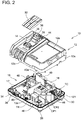
FIG. 2 is an exploded perspective view of thecharger 10 in the embodiment; -
FIG. 3 is a front view of thecharger 10 in the embodiment; -
FIG. 4 is a back view of thecharger 10 in the embodiment; -
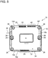
FIG. 5 is a bottom view of thecharger 10 in the embodiment; -
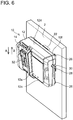
FIG. 6 shows thecharger 10 mounted on awall 2; -
FIG. 7 is a plan view showing an internal structure of thecharger 10; -
FIG. 8 is a circuit diagram of thecharger 10 and abattery pack 100; -
FIG. 9A shows an arrangement of ablower 18 in the embodiment, andFIG. 9B shows an arrangement of ablower 18 which is inclined in another embodiment; -
FIG. 10A shows a plurality ofintake holes 21 in anintake port 20, andFIG. 10B shows a plurality ofexhaust holes 23 in anexhaust port 22; -
FIG. 11 is a diagram showing an embodiment in which afilter 70 is provided in theintake port 20; and -
FIG. 12 is a diagram showing an embodiment in which an opening 72 for thefilter 70 is provided in a housing. - In some embodiments, the blower may be disposed closer to the exhaust port than to the intake port. In other words, a distance from the blower to the exhaust port may be shorter than a distance from the blower to the intake port. In this configuration, the flow of air within the housing is less likely to be disturbed, and thus it is possible to appropriately ventilate the interior of the housing. In an example, the blower may be disposed adjacent to the exhaust port.
- In some embodiments, the housing may include an upper surface and a bottom surface located opposite to the upper surface. In this case, the bottom surface may be disposed along a wall, the intake port may be located along a lower edge of the bottom surface and the exhaust port may be located along an upper edge of the bottom surface, when the housing is mounted on the wall. In this configuration, the flow of air moving upward is formed in a substantially entire interior of the housing, and thus the interior of the housing is effectively ventilated. Since the intake port and the exhaust port are not completely covered with the wall, the flow of air in the intake port and the exhaust port is less likely to be inhibited by the wall.
- In the embodiment described above, the bottom surface of the housing may include a curved portion along the lower edge, the curved portion being curved away from the wall. In this case, the intake port may be at least partly disposed within the curved portion along the lower edge. In this configuration, a space is formed between the intake port and the wall, and thus a flow path for air suctioned by the intake port is acquired. An amount of air suctioned in the intake port is increased, and thus the ventilation within the housing is more facilitated.
- In addition to or instead of the configuration described above, the bottom surface of the housing may include a curved portion along the upper edge, the curved portion being curved away from the wall. In this case, the exhaust port may be at least partly disposed within the curved portion along the upper edge. In this configuration, a space is formed between the exhaust port and the wall, and thus a flow path for air exhausted from the exhaust port is acquired. An amount of air exhausted in the exhaust port is increased, and thus the ventilation within the housing is more facilitated.
- In some embodiments, the blower may be disposed so as to blow air toward the exhaust port along a blowing direction. In this case, the blowing direction may be angled with the wall when the housing is mounted on the wall. Specifically, the blowing direction is not parallel to the wall but may be angled at less than 90 degrees with the wall. In particular, when the exhaust port is disposed along the upper edge of the bottom surface of the housing, the blower may be inclined toward the upper edge (that is, toward a corner portion of the housing).
- In some embodiments, a battery interface may be disposed on the upper surface of the housing. In this configuration, even when the housing is mounted on the wall, a battery pack can be easily attached and detached with respect to the battery interface.
- In some embodiments, the battery interface may be configured to receive the battery pack slidably in a sliding direction. In this case, the sliding direction may become parallel to the vertical direction when the housing is mounted on the wall. In this configuration, a longitudinal direction of the battery interface substantially coincides with a direction of the flow of the air within the housing, and thus the flow of the air within the housing can be prevented from being inhibited by the battery interface and components related thereto.
- In some embodiments, the charger may include a filter disposed on the intake port. In this configuration, it is possible to prevent the intrusion of dust from the intake port. In this case, though there is no particular limitation, an opening for attaching and detaching the filter may be provided in the housing. In this configuration, it is possible to easily clean or replace the filter.
- In some embodiments, the charging circuit may include a transformer. In this case, the blower may be located between the transformer and the exhaust port. The transformer is an electronic component which generates a large amount of heat. When blower is located between the transformer and the exhaust port, the heat generated by the transformer can be effectively exhausted from the exhaust port, and thereby an increase in a temperature of the charging circuit can be effectively reduced.
- In the embodiment described above, the charger may further include a pair of heat sink plates opposed to each other via the transformer. In this case, each of the pair of heat sink plates may become parallel to the vertical direction when the housing is mounted on the wall. In this configuration, a flow path for air is formed between the pair of heat sink plates, and thus the transformer disposed within the flow path can be effectively cooled.
- In the embodiment described above, the charging circuit may include a power semiconductor device disposed on the pair of the heat sink plates. In this configuration, the power semiconductor device is effectively cooled, and thus it is possible to avoid, for example, a heat failure in the power semiconductor device.
- In some embodiments, the intake port and the exhaust port may each include a plurality of holes defined on the housing. In this configuration, sizes of the respective holes are decreased, and thus it is possible to reduce the intrusion of dust in the intake port and the exhaust port.
- Representative, non-limiting examples of the present invention will now be described in further detail with reference to the attached drawings. This detailed description is merely intended to teach a person of skill in the art further details for practicing preferred aspects of the present teachings and is not intended to limit the scope of the invention. Furthermore, each of the additional features and teachings disclosed below may be utilized separately or in conjunction with other features and teachings to provide improved chargers, as well as methods for using and manufacturing the same.
- Moreover, combinations of features and steps disclosed in the following detailed description may not be necessary to practice the invention in the broadest sense, and are instead taught merely to particularly describe representative examples of the invention. Furthermore, various features of the above-described and below-described representative examples, as well as the various independent and dependent claims, may be combined in ways that are not specifically and explicitly enumerated in order to provide additional useful embodiments of the present teachings.
- All features disclosed in the description and/or the claims are intended to be disclosed separately and independently from each other for the purpose of original written disclosure, as well as for the purpose of restricting the claimed subject matter, independent of the compositions of the features in the embodiments and/or the claims. In addition, all value ranges or indications of groups of entities are intended to disclose every possible intermediate value or intermediate entity for the purpose of original written disclosure, as well as for the purpose of restricting the claimed subject matter.
- A
charger 10 of an embodiment will be described with reference to drawings. As shown inFIG. 1 , thecharger 10 is an electrical device for charging abattery pack 100. Thebattery pack 100 is a power supply for an electric power tool (unillustrated) and is configured to be removably attached to the electric power tool. Thecharger 10 of the present embodiment is configured to charge thebattery pack 100 in a state where thebattery pack 100 is removed from the electric power tool. However, in another embodiment, thecharger 10 may be configured to charge thebattery pack 100 in a state where thebattery pack 100 is attached to the electric power tool. - As shown in
FIGS. 1 to 5 , thecharger 10 includes ahousing 12, abattery interface 14, a chargingcircuit 16, and ablower 18. Thebattery interface 14 is provided in thehousing 12, and removably receives thebattery pack 100. The chargingcircuit 16 is provided within thehousing 12, and supplies charging power to thebattery pack 100 that is attached to thebattery interface 14. Theblower 18 ventilates an interior of thehousing 12 so as to reduce an increase in a temperature of the chargingcircuit 16. In an example, thehousing 12 in the present embodiment includes an upper portion 12X and alower portion 12Y which are coupled to each other, and an internal space for storing the chargingcircuit 16 is formed between the upper portion 12X and thelower portion 12Y. The chargingcircuit 16 is connected through anelectrical code 30 to an external AC power supply. - An
intake port 20 and anexhaust port 22 are provided in thehousing 12. Theintake port 20 includes a plurality of intake holes 21 which are formed in thehousing 12, and makes an inside and an outside of thehousing 12 communicate with each other. Theexhaust port 22 includes a plurality of exhaust holes 23 which are formed in thehousing 12, and makes the inside and the outside of thehousing 12 communicate with each other. When theblower 18 is operated, air is introduced through theintake port 20 into thehousing 12, and air is exhausted through theexhaust port 22 to the outside of thehousing 12. In this way, the internal space of thehousing 12 that houses the chargingcircuit 16 is ventilated. - In an example, the
intake port 20 and theexhaust port 22 are provided in thelower portion 12Y of thehousing 12, and are located alongperipheral edges bottom surface 12b in thehousing 12. Theperipheral edge 12e of thebottom surface 12b along which theintake port 20 is located, is located in a boundary between thefront surface 12c and thebottom surface 12b of thehousing 12, and theperipheral edge 12f of thebottom surface 12b along which theexhaust port 22 is located, is located in a boundary between theback surface 12d and thebottom surface 12b of thehousing 12. Thebottom surface 12b includes, along theperipheral edges front surface 12c. Theintake port 20 and theexhaust port 22 are respectively located in the curved portions along theperipheral edges - The
battery interface 14 is located on theupper surface 12a of thehousing 12. Thebattery interface 14 slidably receives thebattery pack 100 along directions A and B inFIG. 1 . A pair of chargingoutput terminals 36 and acommunication connector 38 are provided in thebattery interface 14. Thecommunication connector 38 includes a plurality of communication terminals 39 (seeFIG. 4 ). The pair of chargingoutput terminals 36 and thecommunication terminals 39 are electrically connected to thebattery pack 100 that is attached to thebattery interface 14. - A
movable cover 32 which covers the pair of chargingoutput terminals 36 and thecommunication connector 38 is provided in thebattery interface 14. Although in the present embodiment, thecharger 10 supplies the charging power to thebattery pack 100 by a wired system, in another embodiment, thecharger 10 may supply the charging power to thebattery pack 100 by a wireless system. AUSB port 34 for outputting DC power is provided in thefront surface 12c of thehousing 12. TheUSB port 34 can be connected to an electronic device such as a smart phone, and supplies the charging power or operating power to the electronic device which is connected. - The
charger 10 includes asecond blower 40 for cooling thebattery pack 100 which is being charged. Asecond intake port 42 and asecond exhaust port 44 for thesecond blower 40 are provided in thehousing 12. Thesecond intake port 42 is located along theperipheral edge 12f of thebottom surface 12b in thehousing 12, and thesecond exhaust port 44 is located in thebattery interface 14. Thesecond exhaust port 44 is coupled to thebattery pack 100 that is attached to thebattery interface 14. When thesecond blower 40 is operated, air introduced through thesecond intake port 42 is exhausted through theexhaust outlet 40a of thesecond blower 40. Theexhaust outlet 40a of thesecond blower 40 is connected to thesecond exhaust port 44, and the air from thesecond blower 40 is supplied to thebattery pack 100. In this way, thebattery pack 100 which is being charged is cooled. - As shown in
FIG. 5 , thehousing 12 includes a plurality ofleg portions 26. Theleg portions 26 are provided on thebottom surface 12b of thehousing 12. When thecharger 10 is placed on, for example, a desk or a rack, theleg portions 26 make contact with the surface of the desk or the rack so as to support thecharger 10. Thehousing 12 further includes a plurality ofwall mounting portions 28. Thewall mounting portions 28 are provided on thebottom surface 12b of thehousing 12. In this way, as shown inFIG. 6 , thehousing 12 can be mounted on awall 2 extending in a vertical direction in a predetermined orientation. When thehousing 12 is mounted on thewall 2, thebottom surface 12b of thehousing 12 is disposed along thewall 2. Theintake port 20 is located along thelower edge 12e of thebottom surface 12b, and theexhaust port 22 is located along theupper edge 12f of thebottom surface 12b. In other words, theexhaust port 22 is located higher than theintake port 20 in the vertical direction. The sliding directions A and B of thebattery pack 100 in thebattery interface 14 are parallel to the vertical direction. The term "parallel" herein is not limited to a completely parallel state and includes a state where an angle of less than 15 degrees is formed. In an example, thewall mounting portions 28 in the present embodiment include engagement holes 29 which engage with screws or hooks fixed to thewall 2. Positions, a number and a structure of thewall mounting portions 28 are not particularly limited. Thewall mounting portions 28 may be configured such that thehousing 12 can be mounted on thewall 2 extending in the vertical direction in the predetermined orientation. - The configuration of the charging
circuit 16 will then be described with reference toFIGS. 7 and8 . The chargingcircuit 16 includes acircuit board 17 and a plurality of electronic components (for example, a transformer TR) provided on thecircuit board 17. Although the configuration of the chargingcircuit 16 will be described in detail below, the configuration of the chargingcircuit 16 is not limited thereto. The configuration of the chargingcircuit 16 can be changed as necessary. As shown inFIG. 8 , the chargingcircuit 16 includes a voltagedoubler rectifier circuit 52, a switchingcircuit 54, the transformer TR, a secondaryside rectifier circuit 56, agate driver 58, aphotocoupler 60 and acontroller 62. The voltagedoubler rectifier circuit 52 includes a diode bridge DB, a first capacitor CP1 and a second capacitor CP2, and can convert AC power into DC power. The AC power is supplied to the voltagedoubler rectifier circuit 52 through theelectrical code 30 from outside. The voltagedoubler rectifier circuit 52 converts the supplied AC power into DC power so as to output it to the switchingcircuit 54. The voltagedoubler rectifier circuit 52, a toroidal coil TC for removing a noise current in a common mode is provided between theelectrical code 30 and the voltagedoubler rectifier circuit 52. - The switching
circuit 54 is provided between the voltagedoubler rectifier circuit 52 and the transformer TR, and converts the DC power outputted from the voltagedoubler rectifier circuit 52 into the AC power which is supplied to the transformer TR. In an example, the switchingcircuit 54 includes a first switching device SW1, a second switching device SW2, a third capacitor CP3 and a fourth capacitor CP4. The first switching device SW1 and the second switching device SW2 are controlled by thegate driver 58. Typically, thegate driver 58 alternately turns on the first switching device SW1 and the second switching device SW2 so as to input the AC power to the transformer TR. Here, thegate driver 58 changes duty ratios (turn-on time per period) for the first switching device SW1 and the second switching device SW2 and thereby can adjust the magnitude of the AC power to be supplied to the transformer TR. Although the first switching device SW1 and the second switching device SW2 are not particularly limited, they are power semiconductor devices such as a MOSFET (Metal-Oxide-Semiconductor Field-Effect Transistor). - The AC power supplied to the transformer TR, where the voltage of the AC power is stepped down, is supplied to the secondary
side rectifier circuit 56. The secondaryside rectifier circuit 56 includes a diode DI and a fifth capacitor CP5, and converts the AC power supplied from the transformer TR into DC power. The secondaryside rectifier circuit 56 is connected to the pair of chargingoutput terminals 36, and the DC power from the secondaryside rectifier circuit 56 is supplied as the charging power to thebattery pack 100. The charging power supplied to thebattery pack 100 is monitored by thecontroller 62. For example, thecontroller 62 can detect a charging current supplied to thebattery pack 100, and outputs a control signal corresponding to the detected charging current to thegate driver 58. The control signal is transmitted from thecontroller 62 through thephotocoupler 60 to thegate driver 58. Thegate driver 58 controls, according to the received control signal, the duty ratios for the first switching device SW1 and the second switching device SW2. In this way, the charging current supplied to thebattery pack 100 is feedback controlled. Thecontroller 62 is further connected to thecommunication terminals 39. - As shown in
FIG. 8 , thebattery pack 100 includes a plurality ofsecondary battery cells 104, a pair ofbattery power terminals 106, abattery controller 108, atemperature sensor 110 and a plurality ofbattery communication terminals 112. Although thesecondary battery cells 104 are not particularly limited, they are lithium-ion cells. Thesecondary battery cells 104 are connected to the pair ofbattery power terminals 106. When thebattery pack 100 is attached to thecharger 10, the pair ofbattery power terminals 106 are connected to the pair of chargingoutput terminals 36 in thecharger 10. Thebattery controller 108 can detect voltages of thesecondary battery cells 104. Thetemperature sensor 110 detects temperatures of thesecondary battery cells 104. Thebattery controller 108 and thetemperature sensor 110 are connected to thebattery communication terminals 112. When thebattery pack 100 is attached to thecharger 10, thebattery communication terminals 112 are individually connected to thecommunication terminals 39 in thecharger 10. In this way, thecontroller 62 of thecharger 10 can control an operation of charging thebattery pack 100 according to the voltages and temperatures of thesecondary battery cells 104 in thebattery pack 100. - The
charger 10 of the present embodiment is configured such that thehousing 12 can be mounted on thewall 2 extending in the vertical direction. While thecharger 10 is charging thebattery pack 100, the chargingcircuit 16 within thehousing 12 generates heat. When the chargingcircuit 16 generates heat, air around the chargingcircuit 16 is warmed so as to be moved upward. In this way, flow of air moving upward is formed by heat convection within thehousing 12. On the other hand, in thehousing 12, theintake port 20 and theexhaust port 22 are provided, and theexhaust port 22 is located higher than theintake port 20. In this way, within thehousing 12, the flow of air moving upward is formed by theblower 18. The flow of air formed by theblower 18 substantially coincides with the flow of air by the heat convection, and thus the air warmed by the chargingcircuit 16 is smoothly exhausted to the outside of thehousing 12. In this way, the interior of thehousing 12 is sufficiently ventilated, and thus an increase in the temperature of the chargingcircuit 16 is reduced. - In the
charger 10 of the present embodiment, as shown inFIG. 7 , theblower 18 is disposed adjacent to theexhaust port 22. When as described above, theblower 18 is disposed closer to theexhaust port 22 than to theintake port 20, the flow of air within thehousing 12 is less likely to be disturbed, and thus the interior of thehousing 12 can be appropriately ventilated. In thecharger 10, in addition to theblower 18 adjacent to theexhaust port 22, another blower adjacent to theintake port 20 may be further provided. - In the
charger 10 of the present embodiment, theintake port 20 and theexhaust port 22 are respectively provided along theperipheral edges bottom surface 12b in thehousing 12. A length W20 over which theintake port 20 is provided along theperipheral edge 12e of thebottom surface 12b is longer than a length W22 over which theexhaust port 22 is provided along theperipheral edge 12f of thebottom surface 12b (seeFIG. 7 ). In this configuration, even when areas of the intake holes 21 are individually small, an opening area of theintake port 20 as a whole can be increased. The length W20 over which theintake port 20 is provided is increased, and thus it is possible to reduce increases in temperatures of a large number of electronic components disposed over a wide area within thehousing 12. By contrast, the length W22 over which theexhaust port 22 is provided may be substantially equal to the dimension of theblower 18 or may correspond thereto, and thus air from theblower 18 is efficiently exhausted from theexhaust port 22 and thecharger 10 can also be downsized. - In the
charger 10 of the present embodiment, when thehousing 12 is mounted on thewall 2, thebottom surface 12b of thehousing 12 is disposed along thewall 2, theintake port 20 is located along thelower edge 12e of thebottom surface 12b and theexhaust port 22 is located along theupper edge 12f of thebottom surface 12b. In this way, theintake port 20 is located lower than any of the electronic components of the chargingcircuit 16 which generate heat, and theexhaust port 22 is located higher than any of the electronic components of the chargingcircuit 16 which generate heat. In this configuration, the flow of air moving upward is formed in a substantially entire interior of the housing, and thus the interior of the housing is effectively ventilated. Since theintake port 20 and theexhaust port 22 are not completely covered with the wall, the flow of air in theintake port 20 and theexhaust port 22 is less likely to be inhibited by thewall 2. - In the
charger 10 of the present embodiment, thebottom surface 12b of thehousing 12 includes the curved portion curved away from thewall 2 along thelower edge 12e. At least part of theintake port 20 is provided in the curved portion along thelower edge 12e. Likewise, thebottom surface 12b of thehousing 12 includes the curved portion curved away from thewall 2 along theupper edge 12f. At least part of theexhaust port 22 is provided in the curved portion along theupper edge 12f. In this configuration, spaces are formed between theintake port 20 and thewall 2 and between theexhaust port 22 and thewall 2, and thus flow paths for air are acquired in vicinities of theintake port 20 and theexhaust port 22. Amounts of air flowing in theintake port 20 and theexhaust port 22 are increased, and thus ventilation within thehousing 12 is more facilitated. - In the
charger 10 of the present embodiment, as shown inFIG. 9A , theblower 18 is disposed so as to blow air toward theexhaust port 22. The direction F in which theblower 18 blows the air is substantially parallel to thebottom surface 12b of thehousing 12, and also becomes parallel to thewall 2 when thehousing 12 is mounted on thewall 2. However, in another embodiment, as shown inFIG. 9B , whenhousing 12 is mounted on thewall 2, the direction F in which theblower 18 blows the air may be angled with thewall 2. In this case, direction F in which theblower 18 blows the air is not parallel to thewall 2 but may be angled at less than 90 degrees with thewall 2. As described above, theblower 18 is inclined, and thus the amount of air exhausted in theexhaust port 22 is increased, with the result that the ventilation within thehousing 12 can be more facilitated. - In the
charger 10 of the present embodiment, as shown inFIG. 6 , when thehousing 12 is mounted on thewall 2, the sliding directions A and B of thebattery pack 100 in thebattery interface 14 are parallel to the vertical direction. In this configuration, the longitudinal direction of thebattery interface 14 substantially coincides with the direction of the flow of the air within thehousing 12, and thus the flow of the air within thehousing 12 can be prevented from being inhibited by thebattery interface 14 and components related thereto. - In the
charger 10 of the present embodiment, as shown inFIG. 7 , the chargingcircuit 16 includes the transformer TR. Theblower 18 is disposed between the transformer TR and theexhaust port 22. Among the electronic components of the chargingcircuit 16, in particular, the transformer TR is an electronic component which generates a large amount of heat. Theblower 18 is located between the transformer TR and theexhaust port 22, and thus it is possible to effectively exhaust, from theexhaust port 22, the heat generated by the transformer TR, and thereby effectively reduce an increase in the temperature of the chargingcircuit 16. - The
charger 10 of the present embodiment includes a plurality ofheat sink plates 46 as shown inFIG. 7 . Theheat sink plates 46 are disposed within thehousing 12, and are made to stand on thecircuit board 17 of the chargingcircuit 16. A pair ofheat sink plates 46 opposed to each other via the transformer TR is included in theheat sink plates 46. Each of the pair ofheat sink plates 46 is extended parallel to a direction extending from theintake port 20 toward theexhaust port 22. In this configuration, when thehousing 12 is mounted on thewall 2, the pair ofheat sink plates 46 is parallel to the vertical direction. Aflow path 50 for air which is extended from theintake port 20 to theexhaust port 22 is formed so as to pass between the pair ofheat sink plates 46, and thus the transformer TR disposed within theflow path 50 is effectively cooled. The first switching device SW1 and the second switching device SW2 of the chargingcircuit 16 are disposed on theheat sink plates 46. As described above, the first switching device SW1 and the second switching device SW2 are power semiconductor devices and are electronic components which generate a relatively large amount of heat. In addition to the first switching device SW1 and the second switching device SW2, an electronic component such as a power semiconductor device is disposed on theheat sink plates 46, and thus it is possible to reduce an increase in the temperature thereof. - In the
charger 10 of the present embodiment, as shown inFIGS. 10A and 10B , a shape of each of the intake holes 21 in theintake port 20 and a shape of each of the exhaust holes 23 in theexhaust port 22 differ from each other. In particular, an inscribedcircle 21a of each of the intake holes 21 is smaller than an inscribedcircle 23a of each of the exhaust holes 23. This is because of the following reasons. When the interior of thehousing 12 is ventilated by theblower 18, dust intrudes from theintake port 20 into thehousing 12. In order to reduce the intrusion of dust from theintake port 20, the size of the intake holes 21 in theintake port 20 may be decreased. However, when the size of the intake holes 21 is excessively decreased, the amount of air flowing in theintake port 20 is lowered, and thus it is impossible to sufficiently ventilate the interior of thehousing 12. - As a result of studying various shapes of the intake holes 21 in the above regard, it has been found that even when the areas of the intake holes 21 are the same, in the intake holes 21 in which the inscribed
circle 21a is smaller, a smaller amount of dust is passed through the intake holes 21. This holds true for the exhaust holes 23 in theexhaust port 22. Specifically, even when areas of the exhaust holes 23 are the same, in the exhaust holes 23 in which the inscribedcircle 23a is smaller, a smaller amount of dust is passed through the exhaust holes 23. The inscribed circles 21a of the intake holes 21 are designed to be smaller than the inscribedcircles 23a of the exhaust holes 23 in thecharger 10 of the present embodiment, based on the findings described above. In this configuration, the intrusion of dust from theintake port 20 into thehousing 12 is reduced, and a larger amount of dust that has intruded into thehousing 12 can be exhausted from theexhaust port 22. Consequently, the amount of dust left within thehousing 12 is reduced, and thus, for example, the problem that dust accumulates on the chargingcircuit 16 is reduced. - In the
charger 10 of the present embodiment, each of the areas of the intake holes 21 is smaller than any of the areas of the exhaust holes 23. In this configuration, the amount of dust intruding from the intake holes 21 into thehousing 12 is reduced, and the amount of dust exhausted from the exhaust holes 23 to the outside of thehousing 12 is increased. In this way, it is possible to reduce the amount of dust left within the housing. In addition to or instead, a number of intake holes 21 may be larger than a number of exhaust holes 23. In this configuration, even when the area of each of the intake holes 21 is small, the opening area of theintake port 20 as a whole can be increased. In this case, the intake holes 21 may be arranged in a matrix having a plurality of rows and columns. In this configuration, a large number of intake holes 21 can be formed in a compact range. - As shown in
FIG. 11 , afilter 70 which collects dusts may be provided in theintake port 20 of thehousing 12. Although thefilter 70 is not particularly limited, thefilter 70 may be, for example, a porous filter such as a paper filter, a woven fabric filter, a nonwoven fabric filter, a metal filter or a sponge. In this way, even when the intake holes 21 are set relatively large, it is possible to prevent the intrusion of dust. In this case, the intake holes 21 may be set larger than the exhaust holes 23. As shown inFIG. 12 , anopening 72 for attaching and detaching thefilter 70 may be provided in thehousing 12. In this configuration, it is possible to easily clean or replace thefilter 70. Here, thefilter 70 and structures (for example, the opening 72) related thereto can be adopted similarly in various chargers regardless of whether or not thehousing 12 can be mounted on thewall 2.
Claims (15)
- A charger (10) configured to charge a battery pack (100) of an electric power tool, comprising:a housing (12) comprising an intake port (20) and an exhaust port (22);a battery interface (14) disposed on the housing (12) and configured to removably receive the battery pack (100);a charging circuit (16) disposed within the housing (12) and configured to supply charging power to the battery pack (100) attached to the battery interface (14); anda blower (18) configured to introduce air into the housing (12) through the intake port (20) and exhaust air from the housing (12) through the exhaust port (22),wherein the housing (12) is configured to be mountable on a wall (2) extending in a vertical direction, andthe exhaust port (22) is located higher in the vertical direction than the intake port (20) when the housing (12) is mounted on the wall (2).
- The charger (10) according to claim 1, wherein a distance from the blower (18) to the exhaust port (22) is shorter than a distance from the blower (18) to the intake port (20).
- The charger (10) according to claim 2, wherein the blower (18) is disposed adjacent to the exhaust port (22).
- The charger (10) according to any one of claims 1 to 3, wherein
the housing (12) comprises an upper surface (12a) and a bottom surface (12b) located opposite to the upper surface (12a), and
when the housing (12) is mounted on the wall (2), the bottom surface (12b) is disposed along the wall (2), the intake port (20) is located along a lower edge (12e) of the bottom surface (12b) and the air exhaust port (22) is located along an upper edge (12f) of the bottom surface (12b). - The charger (10) according to claim 4, wherein the bottom surface (12b) of the housing (12) includes a curved portion along the lower edge (12e), the curved portion is curved away from the wall (2), and the intake port (20) is at least partly disposed within the curved portion along the lower edge (12e).
- The charger (10) according to claim 4 or 5, wherein the bottom surface (12b) of the housing (12) includes a curved portion along the upper edge (12f), the curved portion is curved away from the wall (2), and the exhaust port (22) is at least partly disposed within the curved portion along the upper edge (12f).
- The charger (10) according to any one of claims 4 to 6, wherein the blower (18) is disposed so as to blow air toward the exhaust port (22) along a blowing direction (F), and the blowing direction (F) is angled with the wall (2) when the housing (12) is mounted on the wall (2).
- The charger (10) according to any one of claims 4 to 7, wherein the battery interface (14) is disposed on the upper surface (12a) of the housing (12).
- The charger (10) according to any one of claims 1 to 8, wherein the battery interface (14) is configured to receive the battery pack (100) slidably in a sliding direction (A), and the sliding direction (A) becomes parallel to the vertical direction when the housing (12) is mounted on the wall (2).
- The charger (10) according to any one of claims 1 to 9, further comprising a filter (70) disposed on the intake port (20).
- The charger (10) according to claim 10, wherein the housing (12) further comprises an opening (72) for attaching and detaching the filter (70).
- The charger (10) according to any one of claims 1 to 11, wherein the charging circuit (16) comprises a transformer (TR), and the blower (18) is located between the transformer (TR) and the exhaust port (22).
- The charger (10) according to claim 12, further comprising a pair of heat sink plates (46) opposed to each other via the transformer (TR), and each of the pair of heat sink plates (46) becomes parallel to the vertical direction when the housing (12) is mounted on the wall (12).
- The charger (10) according to claim 13, wherein the charging circuit (16) comprises a power semiconductor device (SW1, SW2) disposed on the pair of the heat sink plates (46).
- The charger (10) according to any one of claims 1 to 14, wherein the intake port (20) and the exhaust port (22) each comprises a plurality of holes (21, 23) defined on the housing (12).
Applications Claiming Priority (1)
| Application Number | Priority Date | Filing Date | Title |
|---|---|---|---|
| JP2017098116A JP6920880B2 (en) | 2017-05-17 | 2017-05-17 | Charger to charge the battery pack of power tools |
Publications (2)
| Publication Number | Publication Date |
|---|---|
| EP3404795A1 true EP3404795A1 (en) | 2018-11-21 |
| EP3404795B1 EP3404795B1 (en) | 2020-07-01 |
Family
ID=62116299
Family Applications (1)
| Application Number | Title | Priority Date | Filing Date |
|---|---|---|---|
| EP18170673.0A Active EP3404795B1 (en) | 2017-05-17 | 2018-05-03 | Charger for charging battery pack of electric power tool |
Country Status (4)
| Country | Link |
|---|---|
| US (1) | US10686318B2 (en) |
| EP (1) | EP3404795B1 (en) |
| JP (1) | JP6920880B2 (en) |
| CN (1) | CN108964168A (en) |
Cited By (3)
| Publication number | Priority date | Publication date | Assignee | Title |
|---|---|---|---|---|
| WO2021014016A1 (en) * | 2019-07-24 | 2021-01-28 | Elringklinger Ag | Monitoring device |
| CN115224861A (en) * | 2022-07-22 | 2022-10-21 | 昶旭电子制品(深圳)有限公司 | A multi-interface outdoor barbecue motor device |
| EP4070433A4 (en) * | 2019-12-03 | 2024-04-03 | Milwaukee Electric Tool Corporation | BATTERY PACK AND CHARGER SYSTEM |
Families Citing this family (14)
| Publication number | Priority date | Publication date | Assignee | Title |
|---|---|---|---|---|
| JP2018196242A (en) * | 2017-05-17 | 2018-12-06 | 株式会社マキタ | Charger that charges the battery pack of the power tool |
| US11211804B2 (en) * | 2019-03-19 | 2021-12-28 | Makita Corporation | Electrical device |
| JP2020166988A (en) * | 2019-03-28 | 2020-10-08 | 工機ホールディングス株式会社 | Battery packs, electrical equipment bodies, electrical equipment, chargers, and systems |
| TWI691262B (en) * | 2019-10-08 | 2020-04-21 | 何炳梓 | Electric gardening machine |
| US12078667B1 (en) * | 2020-02-13 | 2024-09-03 | Spirent Communications, Inc. | Positioning and weighting test probes in an anechoic chamber |
| CN112146219B (en) * | 2020-09-30 | 2021-12-21 | 美的集团股份有限公司 | Charging pile, control method thereof and computer-readable storage medium |
| EP4016783B1 (en) | 2020-12-15 | 2023-11-22 | Andreas Stihl AG & Co. KG | Charger with charging electronics unit and cooling air guiding structure |
| WO2022140327A1 (en) | 2020-12-22 | 2022-06-30 | Emerson Professional Tools, Llc | Charge adapter for power tools |
| USD1060222S1 (en) * | 2021-03-18 | 2025-02-04 | Husqvarna Ab | Battery charger |
| WO2023283429A1 (en) * | 2021-07-08 | 2023-01-12 | Milwaukee Electric Tool Corporation | Power tool system |
| CN114069787B (en) * | 2021-11-18 | 2023-11-07 | 天长市天越电子有限公司 | Charger with heat dissipation mechanism |
| US12609545B2 (en) | 2021-12-15 | 2026-04-21 | Milwaukee Electric Tool Corporation | Battery charger with cooling and sealing construction |
| USD1089075S1 (en) * | 2022-04-28 | 2025-08-19 | Positec Power Tools (Suzhou) Co., Ltd. | Charger |
| JP1746633S (en) * | 2022-11-28 | 2023-06-19 | charger |
Citations (5)
| Publication number | Priority date | Publication date | Assignee | Title |
|---|---|---|---|---|
| US20080213652A1 (en) * | 2007-02-08 | 2008-09-04 | Karl Frederick Scheucher | Battery pack safety and thermal management apparatus and method |
| US20080290836A1 (en) * | 2007-01-10 | 2008-11-27 | Mobiletron Electronics Co., Ltd. | Battery charger for power hand tool |
| US8450970B1 (en) * | 2007-05-14 | 2013-05-28 | Micro Power Electronics, Inc. | Small footprint portable battery charging station |
| WO2016067808A1 (en) * | 2014-10-31 | 2016-05-06 | 日立工機株式会社 | Charging device |
| JP2016149841A (en) | 2015-02-10 | 2016-08-18 | 日立工機株式会社 | Charger |
Family Cites Families (13)
| Publication number | Priority date | Publication date | Assignee | Title |
|---|---|---|---|---|
| US6455186B1 (en) | 1998-03-05 | 2002-09-24 | Black & Decker Inc. | Battery cooling system |
| JP3780906B2 (en) * | 2001-11-02 | 2006-05-31 | 日立工機株式会社 | Charger |
| JP2007295677A (en) * | 2006-04-24 | 2007-11-08 | I D Ekusu:Kk | Charger |
| US7868588B2 (en) * | 2007-09-11 | 2011-01-11 | Illinois Tool Works Inc. | Battery charger with wind tunnel cooling |
| GB2471279A (en) | 2009-06-22 | 2010-12-29 | Electrofit Zapi Ltd | Protective enclosure for battery charger |
| JP5706149B2 (en) * | 2010-02-26 | 2015-04-22 | パナソニックIpマネジメント株式会社 | Electrical equipment |
| JP2013168596A (en) * | 2012-02-17 | 2013-08-29 | Mitsubishi Electric Corp | Ventilation device, cooler employing ventilation device and display device with cooler |
| JP2014016327A (en) * | 2012-06-15 | 2014-01-30 | Mitsubishi Heavy Ind Ltd | Method of calculating charging rate of secondary battery, charging rate calculation device, and portable power supply device |
| JP6084523B2 (en) * | 2013-06-25 | 2017-02-22 | 株式会社マキタ | Charger |
| JP6177709B2 (en) * | 2014-02-26 | 2017-08-09 | 株式会社マキタ | Charger |
| JP6456767B2 (en) * | 2015-02-13 | 2019-01-23 | 株式会社マキタ | Luminescent display |
| CN106160036B (en) * | 2015-03-30 | 2019-02-01 | 南京德朔实业有限公司 | Chargers, Charging Combos, and Power Tools with Battery Packs |
| JP6399479B2 (en) * | 2015-06-30 | 2018-10-03 | 工機ホールディングス株式会社 | Charger |
-
2017
- 2017-05-17 JP JP2017098116A patent/JP6920880B2/en active Active
-
2018
- 2018-04-28 CN CN201810399591.2A patent/CN108964168A/en active Pending
- 2018-05-01 US US15/967,919 patent/US10686318B2/en active Active
- 2018-05-03 EP EP18170673.0A patent/EP3404795B1/en active Active
Patent Citations (5)
| Publication number | Priority date | Publication date | Assignee | Title |
|---|---|---|---|---|
| US20080290836A1 (en) * | 2007-01-10 | 2008-11-27 | Mobiletron Electronics Co., Ltd. | Battery charger for power hand tool |
| US20080213652A1 (en) * | 2007-02-08 | 2008-09-04 | Karl Frederick Scheucher | Battery pack safety and thermal management apparatus and method |
| US8450970B1 (en) * | 2007-05-14 | 2013-05-28 | Micro Power Electronics, Inc. | Small footprint portable battery charging station |
| WO2016067808A1 (en) * | 2014-10-31 | 2016-05-06 | 日立工機株式会社 | Charging device |
| JP2016149841A (en) | 2015-02-10 | 2016-08-18 | 日立工機株式会社 | Charger |
Cited By (6)
| Publication number | Priority date | Publication date | Assignee | Title |
|---|---|---|---|---|
| WO2021014016A1 (en) * | 2019-07-24 | 2021-01-28 | Elringklinger Ag | Monitoring device |
| US12243994B2 (en) | 2019-07-24 | 2025-03-04 | Elringklinger Ag | Control device |
| EP4070433A4 (en) * | 2019-12-03 | 2024-04-03 | Milwaukee Electric Tool Corporation | BATTERY PACK AND CHARGER SYSTEM |
| US12015130B2 (en) | 2019-12-03 | 2024-06-18 | Milwaukee Electric Tool Corporation | Charger and charger system |
| US12412936B2 (en) | 2019-12-03 | 2025-09-09 | Milwaukee Electric Tool Corporation | Battery pack and charger system |
| CN115224861A (en) * | 2022-07-22 | 2022-10-21 | 昶旭电子制品(深圳)有限公司 | A multi-interface outdoor barbecue motor device |
Also Published As
| Publication number | Publication date |
|---|---|
| US20180337540A1 (en) | 2018-11-22 |
| EP3404795B1 (en) | 2020-07-01 |
| US10686318B2 (en) | 2020-06-16 |
| JP2018196240A (en) | 2018-12-06 |
| JP6920880B2 (en) | 2021-08-18 |
| CN108964168A (en) | 2018-12-07 |
Similar Documents
| Publication | Publication Date | Title |
|---|---|---|
| EP3404795B1 (en) | Charger for charging battery pack of electric power tool | |
| US11277017B2 (en) | Charger configured to charge battery pack of power tool | |
| EP3082388B1 (en) | Temperature regulated cabinet | |
| US9728822B2 (en) | Battery charger with a fan | |
| US20090191453A1 (en) | Car power source apparatus | |
| CN108352715B (en) | Charging device | |
| TW201427584A (en) | Power storage system | |
| JPWO2013011779A1 (en) | Power storage device | |
| CN204613365U (en) | A kind of portable storage battery service life tester | |
| WO2019091120A1 (en) | Wireless charger | |
| JP5957909B2 (en) | Power converter | |
| CN210327056U (en) | Wireless charger | |
| JP2004286365A (en) | Rack for housing electronic equipment, air conditioning system, control box used therefor, and method of controlling air conditioning system | |
| CN104620485A (en) | Inverter device for air conditioner | |
| JP2019176534A (en) | Storage battery system | |
| JP5684047B2 (en) | Electrical equipment | |
| JP4312160B2 (en) | Uninterruptible power system | |
| JP2024001660A (en) | Energy storage system | |
| JP2004271168A (en) | Outdoor machine of air conditioner | |
| CN218770753U (en) | Embedded type power box shell | |
| JPH025579Y2 (en) | ||
| EP4676163A1 (en) | Battery induction warmer | |
| CN206991148U (en) | A kind of circuit voltage-stabilizing protection device | |
| CN215772673U (en) | Wireless charging device | |
| CN103457179B (en) | Power supply cabinet |
Legal Events
| Date | Code | Title | Description |
|---|---|---|---|
| PUAI | Public reference made under article 153(3) epc to a published international application that has entered the european phase |
Free format text: ORIGINAL CODE: 0009012 |
|
| STAA | Information on the status of an ep patent application or granted ep patent |
Free format text: STATUS: THE APPLICATION HAS BEEN PUBLISHED |
|
| AK | Designated contracting states |
Kind code of ref document: A1 Designated state(s): AL AT BE BG CH CY CZ DE DK EE ES FI FR GB GR HR HU IE IS IT LI LT LU LV MC MK MT NL NO PL PT RO RS SE SI SK SM TR |
|
| AX | Request for extension of the european patent |
Extension state: BA ME |
|
| STAA | Information on the status of an ep patent application or granted ep patent |
Free format text: STATUS: REQUEST FOR EXAMINATION WAS MADE |
|
| 17P | Request for examination filed |
Effective date: 20190416 |
|
| RBV | Designated contracting states (corrected) |
Designated state(s): AL AT BE BG CH CY CZ DE DK EE ES FI FR GB GR HR HU IE IS IT LI LT LU LV MC MK MT NL NO PL PT RO RS SE SI SK SM TR |
|
| STAA | Information on the status of an ep patent application or granted ep patent |
Free format text: STATUS: EXAMINATION IS IN PROGRESS |
|
| 17Q | First examination report despatched |
Effective date: 20190826 |
|
| GRAP | Despatch of communication of intention to grant a patent |
Free format text: ORIGINAL CODE: EPIDOSNIGR1 |
|
| STAA | Information on the status of an ep patent application or granted ep patent |
Free format text: STATUS: GRANT OF PATENT IS INTENDED |
|
| INTG | Intention to grant announced |
Effective date: 20200306 |
|
| GRAS | Grant fee paid |
Free format text: ORIGINAL CODE: EPIDOSNIGR3 |
|
| GRAA | (expected) grant |
Free format text: ORIGINAL CODE: 0009210 |
|
| STAA | Information on the status of an ep patent application or granted ep patent |
Free format text: STATUS: THE PATENT HAS BEEN GRANTED |
|
| AK | Designated contracting states |
Kind code of ref document: B1 Designated state(s): AL AT BE BG CH CY CZ DE DK EE ES FI FR GB GR HR HU IE IS IT LI LT LU LV MC MK MT NL NO PL PT RO RS SE SI SK SM TR |
|
| REG | Reference to a national code |
Ref country code: CH Ref legal event code: EP Ref country code: AT Ref legal event code: REF Ref document number: 1287071 Country of ref document: AT Kind code of ref document: T Effective date: 20200715 |
|
| REG | Reference to a national code |
Ref country code: IE Ref legal event code: FG4D |
|
| REG | Reference to a national code |
Ref country code: DE Ref legal event code: R096 Ref document number: 602018005641 Country of ref document: DE |
|
| REG | Reference to a national code |
Ref country code: LT Ref legal event code: MG4D |
|
| PG25 | Lapsed in a contracting state [announced via postgrant information from national office to epo] |
Ref country code: BG Free format text: LAPSE BECAUSE OF FAILURE TO SUBMIT A TRANSLATION OF THE DESCRIPTION OR TO PAY THE FEE WITHIN THE PRESCRIBED TIME-LIMIT Effective date: 20201001 |
|
| REG | Reference to a national code |
Ref country code: NL Ref legal event code: MP Effective date: 20200701 |
|
| REG | Reference to a national code |
Ref country code: AT Ref legal event code: MK05 Ref document number: 1287071 Country of ref document: AT Kind code of ref document: T Effective date: 20200701 |
|
| PG25 | Lapsed in a contracting state [announced via postgrant information from national office to epo] |
Ref country code: NO Free format text: LAPSE BECAUSE OF FAILURE TO SUBMIT A TRANSLATION OF THE DESCRIPTION OR TO PAY THE FEE WITHIN THE PRESCRIBED TIME-LIMIT Effective date: 20201001 Ref country code: SE Free format text: LAPSE BECAUSE OF FAILURE TO SUBMIT A TRANSLATION OF THE DESCRIPTION OR TO PAY THE FEE WITHIN THE PRESCRIBED TIME-LIMIT Effective date: 20200701 Ref country code: HR Free format text: LAPSE BECAUSE OF FAILURE TO SUBMIT A TRANSLATION OF THE DESCRIPTION OR TO PAY THE FEE WITHIN THE PRESCRIBED TIME-LIMIT Effective date: 20200701 Ref country code: AT Free format text: LAPSE BECAUSE OF FAILURE TO SUBMIT A TRANSLATION OF THE DESCRIPTION OR TO PAY THE FEE WITHIN THE PRESCRIBED TIME-LIMIT Effective date: 20200701 Ref country code: GR Free format text: LAPSE BECAUSE OF FAILURE TO SUBMIT A TRANSLATION OF THE DESCRIPTION OR TO PAY THE FEE WITHIN THE PRESCRIBED TIME-LIMIT Effective date: 20201002 Ref country code: FI Free format text: LAPSE BECAUSE OF FAILURE TO SUBMIT A TRANSLATION OF THE DESCRIPTION OR TO PAY THE FEE WITHIN THE PRESCRIBED TIME-LIMIT Effective date: 20200701 Ref country code: ES Free format text: LAPSE BECAUSE OF FAILURE TO SUBMIT A TRANSLATION OF THE DESCRIPTION OR TO PAY THE FEE WITHIN THE PRESCRIBED TIME-LIMIT Effective date: 20200701 Ref country code: PT Free format text: LAPSE BECAUSE OF FAILURE TO SUBMIT A TRANSLATION OF THE DESCRIPTION OR TO PAY THE FEE WITHIN THE PRESCRIBED TIME-LIMIT Effective date: 20201102 Ref country code: CZ Free format text: LAPSE BECAUSE OF FAILURE TO SUBMIT A TRANSLATION OF THE DESCRIPTION OR TO PAY THE FEE WITHIN THE PRESCRIBED TIME-LIMIT Effective date: 20200701 Ref country code: LT Free format text: LAPSE BECAUSE OF FAILURE TO SUBMIT A TRANSLATION OF THE DESCRIPTION OR TO PAY THE FEE WITHIN THE PRESCRIBED TIME-LIMIT Effective date: 20200701 |
|
| PG25 | Lapsed in a contracting state [announced via postgrant information from national office to epo] |
Ref country code: LV Free format text: LAPSE BECAUSE OF FAILURE TO SUBMIT A TRANSLATION OF THE DESCRIPTION OR TO PAY THE FEE WITHIN THE PRESCRIBED TIME-LIMIT Effective date: 20200701 Ref country code: PL Free format text: LAPSE BECAUSE OF FAILURE TO SUBMIT A TRANSLATION OF THE DESCRIPTION OR TO PAY THE FEE WITHIN THE PRESCRIBED TIME-LIMIT Effective date: 20200701 Ref country code: RS Free format text: LAPSE BECAUSE OF FAILURE TO SUBMIT A TRANSLATION OF THE DESCRIPTION OR TO PAY THE FEE WITHIN THE PRESCRIBED TIME-LIMIT Effective date: 20200701 Ref country code: IS Free format text: LAPSE BECAUSE OF FAILURE TO SUBMIT A TRANSLATION OF THE DESCRIPTION OR TO PAY THE FEE WITHIN THE PRESCRIBED TIME-LIMIT Effective date: 20201101 |
|
| PG25 | Lapsed in a contracting state [announced via postgrant information from national office to epo] |
Ref country code: NL Free format text: LAPSE BECAUSE OF FAILURE TO SUBMIT A TRANSLATION OF THE DESCRIPTION OR TO PAY THE FEE WITHIN THE PRESCRIBED TIME-LIMIT Effective date: 20200701 |
|
| REG | Reference to a national code |
Ref country code: DE Ref legal event code: R097 Ref document number: 602018005641 Country of ref document: DE |
|
| PG25 | Lapsed in a contracting state [announced via postgrant information from national office to epo] |
Ref country code: IT Free format text: LAPSE BECAUSE OF FAILURE TO SUBMIT A TRANSLATION OF THE DESCRIPTION OR TO PAY THE FEE WITHIN THE PRESCRIBED TIME-LIMIT Effective date: 20200701 Ref country code: SM Free format text: LAPSE BECAUSE OF FAILURE TO SUBMIT A TRANSLATION OF THE DESCRIPTION OR TO PAY THE FEE WITHIN THE PRESCRIBED TIME-LIMIT Effective date: 20200701 Ref country code: RO Free format text: LAPSE BECAUSE OF FAILURE TO SUBMIT A TRANSLATION OF THE DESCRIPTION OR TO PAY THE FEE WITHIN THE PRESCRIBED TIME-LIMIT Effective date: 20200701 Ref country code: DK Free format text: LAPSE BECAUSE OF FAILURE TO SUBMIT A TRANSLATION OF THE DESCRIPTION OR TO PAY THE FEE WITHIN THE PRESCRIBED TIME-LIMIT Effective date: 20200701 Ref country code: EE Free format text: LAPSE BECAUSE OF FAILURE TO SUBMIT A TRANSLATION OF THE DESCRIPTION OR TO PAY THE FEE WITHIN THE PRESCRIBED TIME-LIMIT Effective date: 20200701 |
|
| PLBE | No opposition filed within time limit |
Free format text: ORIGINAL CODE: 0009261 |
|
| STAA | Information on the status of an ep patent application or granted ep patent |
Free format text: STATUS: NO OPPOSITION FILED WITHIN TIME LIMIT |
|
| PG25 | Lapsed in a contracting state [announced via postgrant information from national office to epo] |
Ref country code: AL Free format text: LAPSE BECAUSE OF FAILURE TO SUBMIT A TRANSLATION OF THE DESCRIPTION OR TO PAY THE FEE WITHIN THE PRESCRIBED TIME-LIMIT Effective date: 20200701 |
|
| 26N | No opposition filed |
Effective date: 20210406 |
|
| PG25 | Lapsed in a contracting state [announced via postgrant information from national office to epo] |
Ref country code: SK Free format text: LAPSE BECAUSE OF FAILURE TO SUBMIT A TRANSLATION OF THE DESCRIPTION OR TO PAY THE FEE WITHIN THE PRESCRIBED TIME-LIMIT Effective date: 20200701 |
|
| PG25 | Lapsed in a contracting state [announced via postgrant information from national office to epo] |
Ref country code: SI Free format text: LAPSE BECAUSE OF FAILURE TO SUBMIT A TRANSLATION OF THE DESCRIPTION OR TO PAY THE FEE WITHIN THE PRESCRIBED TIME-LIMIT Effective date: 20200701 |
|
| REG | Reference to a national code |
Ref country code: CH Ref legal event code: PL |
|
| PG25 | Lapsed in a contracting state [announced via postgrant information from national office to epo] |
Ref country code: CH Free format text: LAPSE BECAUSE OF NON-PAYMENT OF DUE FEES Effective date: 20210531 Ref country code: LI Free format text: LAPSE BECAUSE OF NON-PAYMENT OF DUE FEES Effective date: 20210531 Ref country code: LU Free format text: LAPSE BECAUSE OF NON-PAYMENT OF DUE FEES Effective date: 20210503 Ref country code: MC Free format text: LAPSE BECAUSE OF FAILURE TO SUBMIT A TRANSLATION OF THE DESCRIPTION OR TO PAY THE FEE WITHIN THE PRESCRIBED TIME-LIMIT Effective date: 20200701 |
|
| REG | Reference to a national code |
Ref country code: BE Ref legal event code: MM Effective date: 20210531 |
|
| PG25 | Lapsed in a contracting state [announced via postgrant information from national office to epo] |
Ref country code: IE Free format text: LAPSE BECAUSE OF NON-PAYMENT OF DUE FEES Effective date: 20210503 |
|
| PG25 | Lapsed in a contracting state [announced via postgrant information from national office to epo] |
Ref country code: BE Free format text: LAPSE BECAUSE OF NON-PAYMENT OF DUE FEES Effective date: 20210531 |
|
| PG25 | Lapsed in a contracting state [announced via postgrant information from national office to epo] |
Ref country code: CY Free format text: LAPSE BECAUSE OF FAILURE TO SUBMIT A TRANSLATION OF THE DESCRIPTION OR TO PAY THE FEE WITHIN THE PRESCRIBED TIME-LIMIT Effective date: 20200701 |
|
| PG25 | Lapsed in a contracting state [announced via postgrant information from national office to epo] |
Ref country code: HU Free format text: LAPSE BECAUSE OF FAILURE TO SUBMIT A TRANSLATION OF THE DESCRIPTION OR TO PAY THE FEE WITHIN THE PRESCRIBED TIME-LIMIT; INVALID AB INITIO Effective date: 20180503 |
|
| PG25 | Lapsed in a contracting state [announced via postgrant information from national office to epo] |
Ref country code: MK Free format text: LAPSE BECAUSE OF FAILURE TO SUBMIT A TRANSLATION OF THE DESCRIPTION OR TO PAY THE FEE WITHIN THE PRESCRIBED TIME-LIMIT Effective date: 20200701 |
|
| PG25 | Lapsed in a contracting state [announced via postgrant information from national office to epo] |
Ref country code: MT Free format text: LAPSE BECAUSE OF FAILURE TO SUBMIT A TRANSLATION OF THE DESCRIPTION OR TO PAY THE FEE WITHIN THE PRESCRIBED TIME-LIMIT Effective date: 20200701 |
|
| PGFP | Annual fee paid to national office [announced via postgrant information from national office to epo] |
Ref country code: DE Payment date: 20250402 Year of fee payment: 8 |
|
| PGFP | Annual fee paid to national office [announced via postgrant information from national office to epo] |
Ref country code: FR Payment date: 20250401 Year of fee payment: 8 |
|
| PG25 | Lapsed in a contracting state [announced via postgrant information from national office to epo] |
Ref country code: TR Free format text: LAPSE BECAUSE OF FAILURE TO SUBMIT A TRANSLATION OF THE DESCRIPTION OR TO PAY THE FEE WITHIN THE PRESCRIBED TIME-LIMIT Effective date: 20200701 |
|
| PGFP | Annual fee paid to national office [announced via postgrant information from national office to epo] |
Ref country code: GB Payment date: 20260323 Year of fee payment: 9 |