EP3404634A1 - Sensor network system, sensing module, server, and association method - Google Patents
Sensor network system, sensing module, server, and association method Download PDFInfo
- Publication number
- EP3404634A1 EP3404634A1 EP16885125.1A EP16885125A EP3404634A1 EP 3404634 A1 EP3404634 A1 EP 3404634A1 EP 16885125 A EP16885125 A EP 16885125A EP 3404634 A1 EP3404634 A1 EP 3404634A1
- Authority
- EP
- European Patent Office
- Prior art keywords
- sensor
- server
- pattern
- sensing
- information
- Prior art date
- Legal status (The legal status is an assumption and is not a legal conclusion. Google has not performed a legal analysis and makes no representation as to the accuracy of the status listed.)
- Granted
Links
Images



Classifications
-
- H—ELECTRICITY
- H04—ELECTRIC COMMUNICATION TECHNIQUE
- H04W—WIRELESS COMMUNICATION NETWORKS
- H04W64/00—Locating users or terminals or network equipment for network management purposes, e.g. mobility management
- H04W64/006—Locating users or terminals or network equipment for network management purposes, e.g. mobility management with additional information processing, e.g. for direction or speed determination
-
- G—PHYSICS
- G01—MEASURING; TESTING
- G01D—MEASURING NOT SPECIALLY ADAPTED FOR A SPECIFIC VARIABLE; ARRANGEMENTS FOR MEASURING TWO OR MORE VARIABLES NOT COVERED IN A SINGLE OTHER SUBCLASS; TARIFF METERING APPARATUS; MEASURING OR TESTING NOT OTHERWISE PROVIDED FOR
- G01D21/00—Measuring or testing not otherwise provided for
-
- H—ELECTRICITY
- H04—ELECTRIC COMMUNICATION TECHNIQUE
- H04L—TRANSMISSION OF DIGITAL INFORMATION, e.g. TELEGRAPHIC COMMUNICATION
- H04L67/00—Network arrangements or protocols for supporting network services or applications
- H04L67/01—Protocols
- H04L67/12—Protocols specially adapted for proprietary or special-purpose networking environments, e.g. medical networks, sensor networks, networks in vehicles or remote metering networks
-
- H—ELECTRICITY
- H04—ELECTRIC COMMUNICATION TECHNIQUE
- H04L—TRANSMISSION OF DIGITAL INFORMATION, e.g. TELEGRAPHIC COMMUNICATION
- H04L67/00—Network arrangements or protocols for supporting network services or applications
- H04L67/34—Network arrangements or protocols for supporting network services or applications involving the movement of software or configuration parameters
-
- H—ELECTRICITY
- H04—ELECTRIC COMMUNICATION TECHNIQUE
- H04Q—SELECTING
- H04Q9/00—Arrangements in telecontrol or telemetry systems for selectively calling a substation from a main station, in which substation desired apparatus is selected for applying a control signal thereto or for obtaining measured values therefrom
-
- H—ELECTRICITY
- H04—ELECTRIC COMMUNICATION TECHNIQUE
- H04W—WIRELESS COMMUNICATION NETWORKS
- H04W24/00—Supervisory, monitoring or testing arrangements
- H04W24/02—Arrangements for optimising operational condition
-
- H—ELECTRICITY
- H04—ELECTRIC COMMUNICATION TECHNIQUE
- H04W—WIRELESS COMMUNICATION NETWORKS
- H04W84/00—Network topologies
- H04W84/18—Self-organising networks, e.g. ad-hoc networks or sensor networks
- H04W84/22—Self-organising networks, e.g. ad-hoc networks or sensor networks with access to wired networks
-
- G—PHYSICS
- G08—SIGNALLING
- G08C—TRANSMISSION SYSTEMS FOR MEASURED VALUES, CONTROL OR SIMILAR SIGNALS
- G08C2201/00—Transmission systems of control signals via wireless link
- G08C2201/90—Additional features
- G08C2201/93—Remote control using other portable devices, e.g. mobile phone, PDA, laptop
-
- H—ELECTRICITY
- H04—ELECTRIC COMMUNICATION TECHNIQUE
- H04Q—SELECTING
- H04Q2209/00—Arrangements in telecontrol or telemetry systems
- H04Q2209/70—Arrangements in the main station, i.e. central controller
-
- H—ELECTRICITY
- H04—ELECTRIC COMMUNICATION TECHNIQUE
- H04Q—SELECTING
- H04Q2209/00—Arrangements in telecontrol or telemetry systems
- H04Q2209/80—Arrangements in the sub-station, i.e. sensing device
Definitions
- the present invention relates to a sensor network system, a sensing module, a server, and an association method.
- Patent Document 1 describes a sensor network system in which sensors are able to communicate with each other and data of each sensor is communicated to a parent apparatus through multi-hop transmission (relaying) by multiple sensors. The parent apparatus uses the number of hops to estimate the approximate position of a sensor.
- Patent Document 1 International PCT Patent Application Publication No. WO 2014/013578
- a sensor and the position of the sensor cannot be associated with each other unless the sensor is used for multi-hop data transmission. Further, according to the technique of Patent Document 1, because the number of hops is used, the position of a sensor can only be estimated, and as such, the sensor and the position of the sensor cannot be accurately associated with each other. Further, because the position of an antenna associated with a sensor is regarded as the position of the sensor, the position of the sensor cannot be accurately determined in a case where the antenna and the sensor are separated from each other. Also, a moving object having a sensor attached thereto cannot be identified. In other words, a sensor cannot be accurately associated with a sensor position or a sensor installation target, such as a moving object to which the sensor is attached, for example.
- the present invention has been conceived in view of the above-described problems of the related art, and an object of the present invention is to provide a sensor network system, a sensing module, a server, and an association method for accurately associating a sensor with a sensor installation target (e.g., sensor position, moving object to which the sensor is attached).
- a sensor installation target e.g., sensor position, moving object to which the sensor is attached.
- a sensor network system includes a server, one or more sensing modules including one or more sensors configured to detect a physical quantity, and at least one generating module.
- the generating module includes a signal generator configured to generate a signal by varying the physical quantity to be detected by a sensor of the one or more sensors included in a sensing module of the one or more sensing modules.
- the generating module is further configured to communicate installation target information identifying an installation target of the sensor to the server.
- the generating module further includes a signal control unit configured to control the signal generator to generate the signal that includes a set pattern including a specific pattern.
- the sensing module further includes a sensing-side communication device configured to communicate with the server, and a pattern detection information transmitting unit configured to transmit to the server, via the sensing-side communication device, pattern detection information generated in response to the sensor detecting the specific pattern and sensor identification information identifying the sensor that has detected the specific pattern.
- the server further includes a server-side communication device configured to communicate with the sensing-side communication device, and a storage control unit configured to store association information associating the sensor identification information received by the server-side communication device from the sensing module that has transmitted the pattern detection information with the installation target information transmitted from the generating module that has generated the specific pattern.
- sensor identification information identifying a sensor and installation target information identifying the installation target of the sensor are stored in association with each other in the server, and in this way, a sensor and the installation target of the sensor may be accurately associated with each other. Further, a sensor and the installation target of the sensor can be associated with each other using a physical quantity detection function of the sensor, and in this way, the configuration of the sensing module can be simplified as compared with a case where a function for associating a sensor with its installation target has to be added.
- a sensor and the installation target of the sensor can be associated with each other through relatively simple operations of generating and detecting a specific pattern, and in this way, human labor may be reduced and human operation errors due to erroneous association may be reduced as compared with a case where a human has to manually input the sensor identification information and the installation target information.
- the signal control unit controls the signal generator to generate the set pattern that further includes the installation target information
- the pattern detection information transmitting unit generates the pattern detection information that includes the installation target information included in the set pattern
- the storage control unit acquires the installation target information from the pattern detection information
- installation target information is included in the set pattern, and the sensing module that has detected the set pattern communicates both the installation target information and the sensor identification information to the server.
- association of a sensor with its installation target may be more reliably performed with a simple configuration as compared with a case where the installation target information and the sensor identification information are separately communicated to the server.
- the generating module further includes a generating-side communication device configured to communicate with the server, and an installation target information transmitting unit configured to transmit the installation target information to the server via the generating-side communication device.
- the generating module communicates the installation target information directly to the server, and in this way, the installation target information may be reliably communicated.
- the sensing module further includes a selecting unit configured to select at least one operation mode from among a plurality of operation modes including a standby mode and a non-standby mode, the storage control unit stores the association information when the standby mode is selected by the selecting unit, and the storage control unit does not store the association information when the non-standby mode is selected by the selecting unit.
- a selecting unit configured to select at least one operation mode from among a plurality of operation modes including a standby mode and a non-standby mode
- the storage control unit stores the association information when the standby mode is selected by the selecting unit, and the storage control unit does not store the association information when the non-standby mode is selected by the selecting unit.
- a selection can be made between the standby mode in which association information is stored and the non-standby mode in which association information is not stored.
- the sensing module can execute operations suitable for communicating sensor identification information and installation target information
- the non-standby mode when the non-standby mode is selected, the sensing module can execute operations suitable for implementing its primary detection function and other operations according to the situation without regard to whether the operations are suitable for communicating sensor identification information and installation target information.
- the sensing module further includes a sensor control unit, and the sensor control unit enables detection of the set pattern by the sensor in response to the standby mode being selected by the selecting unit.
- the sensing module enables detection of a set pattern by the sensor when the standby mode is selected. In this way, even if the sensor is not capable of detecting a set pattern when the non-standby mode is selected, the sensor can still reliable detect a set pattern at least when the standby mode is selected.
- the sensor control unit disables detection of the set pattern by the sensor in response to the non-standby mode being selected by the selecting unit.
- the sensing module disables detection of a set pattern by the sensor when the non-standby mode is selected. In this way, pattern detection can be prevented when association information does not have to be stored. Even if the sensor may have to perform special operations when the standby mode is selected, the sensor can perform other operations without being influenced by such special operations when the non-standby mode is selected.
- the pattern detection information transmitting unit transmits both the sensor identification information and the pattern detection information to the server via the sensing-side communication device when the standby mode is selected by the selecting unit, and the pattern detection information transmitting unit does not transmit at least one of the sensor identification information and the pattern detection information to the server via the sensing-side communication device when the non-standby mode is selected by the selecting unit.
- pattern detection information in standby mode that involves storing association information, can be reliably communicated from the sensing module to the server, and in non-standby mode that does not require storing association information, unnecessary communication between the sensing module and the server may be prevented.
- the storage control unit stores the association information in response to receiving the pattern detection information from the sensing module that has the standby mode selected, and the storage control unit does not store the association information in response to receiving the pattern detection information from the sensing module that has the non-standby mode selected.
- the storage control unit of the server determines whether association information is to be stored.
- the sensing module can perform the same operations in standby mode and non-standby mode such that the configuration of the sensing module can be simplified.
- the server further includes a standby command transmitting unit configured to transmit a standby command to at least one sensing module of the one or more sensing modules via the server-side communication device, and the selecting unit selects the standby mode in response to the sensing-side communication device receiving the standby command.
- a standby command may be issued so that the standby mode can be reliably selected.
- the generating module further includes a trigger signal transmitting unit configured to transmit a trigger signal via the generating-side communication device, the standby command transmitting unit transmits the standby command in response to the server-side communication device receiving the trigger signal, and the signal control unit controls the signal generator to generate the signal including the set pattern during a period including a time after the trigger signal is transmitted.
- the sensing module selects the standby mode based on a trigger signal. In this way, the sensing module can easily detect a set pattern included in a signal that is generated by the generating module after transmitting the trigger signal.
- the selecting unit selects the non-standby mode after a predetermined waiting period elapses from a time the standby mode is selected.
- a sensing module that is not receiving a set pattern can be prevented from operating in the standby mode for an unnecessarily long time so that operations in the non-standby mode may not be unnecessarily hindered.
- the sensing module further includes a non-detection information transmitting unit configured to transmit, via the sensing-side communication device, non-detection information indicating that the specific pattern has not been detected when the sensor does not detect the specific pattern during a predetermined period after the standby mode is selected.
- the server may be explicitly notified of the sensing module that has not detected a specific pattern, and in this way, a sensor and the installation target of the sensor may be more accurately associated with each other. Also, according to an aspect of the above embodiment, the server may be prevented from having to wait for an unnecessarily long time to receive pattern detection information from the sensing module.
- the server further includes a stop command transmitting unit configured to transmit a stop command via the server-side communication device in response to receiving the pattern detection information, and the signal control unit controls the signal generator to stop generation of the signal including the set pattern in response to receiving the stop command via the generating-side communication device.
- the server when the server receives pattern detection information, the server transmits a stop command.
- the generating module may be prevented from generating a set pattern for an unnecessarily long period.
- the physical quantity is an intensity of light.
- a set pattern represented by a variation in light intensity may be selectively transmitted to a specific sensing module from among the plurality of sensing modules.
- an association method is provided that is to be implemented by a sensor network system including one or more sensing modules including one or more sensors configured to detect a physical quantity, at least one generating module including a signal generator configured to generate a signal by varying the physical quantity to be detected by a sensing module of the one or more sensors included in a sensing module of the one or more sensing modules, the generating module being configured to communicate installation target information identifying an installation target of the sensor to a server, and the server that is capable of communicating with the sensing module and the generating module.
- the association method includes the generating module controlling the signal generator to generate the signal that includes a set pattern including a specific pattern; the sensing module transmitting to the server, pattern detection information generated in response to the sensor detecting the specific pattern and sensor identification information identifying the sensor that has detected the specific pattern; and the server storing association information associating the sensor identification information received from the sensing module that has transmitted the pattern detection information with the installation target information communicated from the generating module that has generated specific pattern.
- a sensing module is provided that is used in a sensor network system including a server configured to store association information associating sensor identification information identifying a sensor that has detected a specific pattern represented by a variation in a physical quantity with installation target information identifying an installation target of the sensor, the installation target information being communicated from a generating module that has generated a signal including a set pattern that includes the specific pattern.
- the sensing module includes the sensor that is configured to detect the physical quantity; a sensing-side communication device configured to communicate with the server; and a pattern detection information transmitting unit configured to transmit to the server, via the sensing-side communication device, the pattern detection information generated in response to the sensor detecting the specific pattern and the sensor identification information identifying the sensor that has detected the specific pattern.
- a server is provided that is used in a sensor network system including one or more sensing modules including one or more sensors configured to detect a physical quantity and at least one generating module configured to generate a signal that includes a set pattern including a specific pattern by varying the physical quantity to be detected by a sensor of the one or more sensors included in a sensing module of the one or more sensing modules, the generating module further being configured to communicate installation target information identifying an installation target of the sensor.
- the server includes a server-side communication device configured to receive from the sensing module, pattern detection information generated in response to the sensor detecting the specific pattern and sensor identification information identifying the sensor that has detected the specific pattern; and a storage control unit configured to store association information associating the sensor identification information received by the server-side communication device from the sensing module that has transmitted the pattern detection information with the installation target information communicated from the generating module that has generated the specific pattern.
- a sensor and an installation target of the sensor can be accurately associated with each other.
- FIG. 1 is a block diagram showing an example configuration of a sensor network system 100 according to the present embodiment.
- the sensor network system 100 includes one or more sensing modules 200, one or more generating modules 300, and a server 400.
- the server 400 manages association information 421.
- the association information 421 is information associating a sensor 210 included in the sensing module 200 with a corresponding installation target of the sensor 210.
- the server 400 manages detections obtained by the sensor 210 based on the association information 421. Note that the present description mainly illustrates embodiments of a system, an apparatus, and a method relating to storing association information associating sensors 210 with their respective installation targets in the server 400.
- the installation target of the sensor 210 may be a position represented by latitude and longitude, or some other item, such as a room in which the sensor 210 is installed, a position within a room in which the sensor 210 is installed, a factory assembly line in which the sensor 210 is installed, a part of a robot in which the sensor 210 is installed, a moving body in which the sensor 210 is installed, a person that is carrying the sensor 210, or a detection target of the sensor 210 (especially when the sensor 210 and the detection target are separated from each other), for example.
- the installation target is not limited to the above examples.
- the installation target is identified by installation target information 351, which is described below.
- the server 400 may be able to recognize the specific room in which the sensor 210 is to detect a physical quantity.
- the association between the installation target information 351 and the installation target may be pre-set in the server 400, set up as desired by an operator, or set up in some other manner, for example.
- a single sensing module 200 includes a plurality of sensors 210.
- An operator sequentially places one sensing module 200 in each of a plurality of rooms.
- each sensing module 200 has a first sensor 210a that detects the brightness of a room and a second sensor 210b that detects the temperature of a room.
- the operator carries one generating module 300.
- the operator installs a sensing module 200 in each room, the operator transmits light from the generating module 300 to the sensor 210a of the sensing module 200 to register the association information 421 in the server 400.
- a plurality of operators may each carry one generating module 300, for example.
- the sensing module 200 includes the first sensor 210a, the second sensor 210b, a sensing-side communication device 220, a storage device 230, and a processor 240.
- the first sensor 201a and the second sensor 210b may generically be referred to as "sensor 210".
- a plurality of sensors 210 of a plurality of sensing modules 200 included in the sensor network system 100 may generically be referred to as "sensors 210".
- the above components of the sensing module 200 may be physically separable from each other, for example.
- the first sensor 210a detects light as a physical quantity.
- the second sensor 210b detects the temperature as a physical quantity.
- the sensing module 200 may include three or more sensors 210.
- the sensing module 200 may include a plurality of sensors 210 that detect the same physical quantity, or the sensing module 200 may include a plurality of sensors 210 that detect different physical quantities.
- the physical quantity to be detected by the sensor 210 is not limited to the examples described in the present embodiment. Examples of physical quantities to be detected include, but are not limited to, temperature, humidity, moisture, heat, density, viscosity, flow rate, pressure, acceleration, vibration, strain, light, magnetism, displacement, position, and rotation.
- the sensing-side communication device 220 communicates with a server-side communication device 410 of the server 400 (described below) via a communication network 500.
- the communication network 500 may be a wireless network, a wired network, or a combination thereof, for example.
- the storage device 230 stores a sensing module program to be executed by the sensing module 200.
- the sensing module program when read and executed by the processor 240, causes the processor 240 to implement various functions including a function of performing a part of an association method according to the present embodiment.
- the storage device 230 is controlled by the processor 240 to store necessary information.
- the storage device 230 is a non-transitory tangible storage medium.
- the storage device 230 includes a ROM (read only memory) and a RAM (random access memory).
- the storage device 230 may be a volatile storage medium or a non-volatile storage medium. Also, the storage device 230 may be a removable storage medium or a non-removable storage medium.
- the storage device 230 further stores sensor identification information 231.
- the sensor identification information 231 is information identifying each of a plurality of sensors 210 included in the sensor network system 100.
- the processor 240 reads and executes the sensing module program stored in the storage device 230 to implement functions of a pattern detection information transmitting unit 241, a selecting unit 242, a sensor control unit 243, and a non-detection information transmitting unit 244.
- the processor 240 may also be an application specific integrated circuit (ASIC) or some other circuit that is capable of implementing the functions described in the present embodiment.
- ASIC application specific integrated circuit
- the pattern detection information transmitting unit 241 generates pattern detection information in response to the sensor 210 detecting a specific pattern as described below.
- the specific pattern is a signal indicating the start of operations for registering association information 421.
- the pattern detection information is a signal indicating that a specific pattern has been detected.
- the pattern detection information transmitting unit 241 generates the pattern detection information in response to detecting the specific pattern and includes installation target information 351 in the pattern detection information.
- the generating module 300 generates a signal including a set pattern that includes the installation target information 351 and the specific pattern.
- the generating module 300 transmits the specific pattern included in the set pattern, followed by the installation target information 351.
- the pattern detection information transmitting unit 241 transmits to the server 400, via the sensing-side communication device 220, the pattern detection information including the installation target information 351 and the sensor identification information 231 identifying the sensor 210 that has detected the specific pattern. For example, when a specific pattern that is communicated by light is detected by the first sensor 210a of a sensing module 200, sensor identification information 231 identifying the sensors 210 included in the sensing module 200 from among a plurality of sensing modules 200 is transmitted to the server 400. Note that the same sensor identification information 231 may be assigned to the plurality of sensors 210 included in one sensing module 200, or different sensor identification information 231 may be assigned to each of the plurality of sensors 210.
- each of the plurality of sensors 210 included in one sensing module 200 may be associated with the same installation target or a different installation target.
- the same sensor identification information 231 is assigned to the plurality of sensors 210 included in one sensing module 200.
- the plurality of sensors 210 included in one sensing module 200 are all associated with the same installation target.
- the pattern detection information transmitting unit 241 may transmit all detections obtained by the sensor 210 to the server 400 without determining whether a specific pattern has been detected.
- detection of a specific pattern among the detections corresponds to the pattern detection information.
- the server 400 extracts from all the detections of the sensor 210, the detection corresponding to the pattern detection information generated in response to the sensor 210 detecting the specific pattern.
- the selecting unit 242 selects at least one of a plurality of operation modes.
- the plurality of operation modes include a standby mode and a non-standby mode.
- the sensor network system 100 is configured such that when the standby mode is selected by the selecting unit 242, a storage control unit 432 of the server 400 stores association information 421 as described below. Further, the sensor network system 100 is configured such that when the non-standby mode is selected by the selecting unit 242, the storage control unit 432 of the server 400 does not store association information 421 as described below.
- Examples of the non-standby mode may include an operation mode to stop detection and an operation mode for normal detection. In the present embodiment, the non-standby mode collectively refers to states in which the standby mode is not selected.
- the selecting unit 242 selects the standby mode when the sensing-side communication device 220 receives a standby command from the server 400. Then, when a predetermined waiting period elapses from the time the selecting unit 242 selects the standby mode, the selecting unit 242 selects the non-standby mode.
- the sensor control unit 243 enables detection of a set pattern by the sensor 210 in response to the selecting unit 242 selecting the standby mode.
- the sensor control unit 243 disables detection of a set pattern by the sensor 210 in response to the selecting unit 242 selecting the non-standby mode.
- the first sensor 210a detects the intensity of light once per hour
- the set pattern corresponds to a light intensity variation per second.
- the sensor control unit 243 controls the first sensor 210a to be capable of detecting the light intensity variation per second
- the non-standby mode the sensor control unit 243 controls the first sensor 210a to detect the intensity of light once per hour. In this way, for example, even if energy consumption of the first sensor 210a may be relatively high in the standby mode, when a set pattern does not have to be detected, the non-standby mode with lower energy consumption may be selected to reduce energy consumption.
- the non-detection information transmitting unit 244 transmits to the server 400, via the sensing-side communication device 220, sensor identification information 231 identifying the sensor 210 that did not detect a specific pattern and non-detection information indicating that the specific pattern has not been detected. Based on the non-detection information, the server 400 may be explicitly notified that the sensor 210 has not detected a specific pattern.
- the generating module 300 includes a signal generator 310, a generating-side communication device 320, a display unit 330, an operation unit 340, a storage device 350, and a processor 360.
- the generating module 300 according to the present embodiment is a smart phone. Note that the above components of the generating module 300 may be physically separated from each other, for example.
- the signal generator 310 generates a signal by varying a physical quantity to be detected by at least one sensor 210 of at least one sensing module 200.
- the signal generator 310 in the present embodiment is a light source that generates light to be detected by the first sensor 210a.
- the light source may be a built-in flashlight, an external light emitting diode, or a built-in display, for example.
- the signal generator 310 may be a heater, a cooler, a humidifier, a dehumidifier, a pressure pump, a vibration generator, or an electromagnets, for example.
- the generating-side communication device 320 communicates with the server-side communication device 410 of the server 400 (described below) via the communication network 500.
- the communication network 500 may be a wireless network, a wired network, or a combination thereof.
- the display unit 330 presents text, images, video, and the like to the operator.
- the display unit 330 may be a liquid crystal display, for example.
- the operation unit 340 receives an input from the operator.
- the operation unit 340 may be an electrostatic capacitive input device, a mechanical button, or a mechanical slider.
- the display unit 330 and the operation unit 340 are integrated to constitute a capacitive touch panel display.
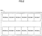
- FIG. 2 shows an example screen display of the display unit 330.
- a layout drawing of actual rooms A to L is displayed on the display unit 330.
- the operation unit 340 detects the room that has been touched by the operator.
- the storage device 350 shown in FIG. 1 stores the installation target information 351 and a generating module program to be executed by the generating module 300.
- the generating module program when read and executed by the processor 360, causes the processor 360 to implement various functions including a function of performing a part of an association method according to the present embodiment.
- the storage device 350 is controlled by the processor 360 to store necessary information.
- the storage device 350 is a non-transitory tangible storage medium.
- the storage device 350 includes a ROM and a RAM.
- the storage device 350 may be a volatile storage medium or a non-volatile storage medium. Also, the storage device 350 may be a removable storage medium or a non-removable storage medium.
- the processor 360 reads and executes the generating module program stored in the storage device 350 to implement functions of a trigger signal transmitting unit 361 and a signal control unit 362.
- the processor 360 in the present embodiment is a general-purpose computer, the processor 360 may also be an application specific integrated circuit (ASIC) or some other circuit that is capable of implementing the function of the embodiments described below.
- ASIC application specific integrated circuit
- the trigger signal transmitting unit 361 transmits a trigger signal to the server 400 via the generating-side communication device 320.
- the trigger signal indicates the start of operations for generating a signal including a set pattern as described below.
- the trigger signal transmitting unit 361 transmits a trigger signal.
- a trigger signal may be transmitted at some other timing, such as when the power of the generating module 300 is turned on, for example.
- the signal control unit 362 controls the signal generator 310 to generate a signal including a set pattern by varying a physical quantity.
- the set pattern includes a specific pattern and installation target information 351.
- the signal generator 310 is a light source
- the set pattern corresponds to a light intensity variation.
- the set pattern may be an analog signal or a digital signal.
- the signal control unit 362 controls the display unit 330 to display the screen of FIG. 2 and receives notification of the room that has been touched by the operator from the operation unit 340.
- the signal control unit 362 generates a communication frame including a specific pattern, followed by installation target information 351 corresponding to the room that has been touched. That is, the generating module 300 transmits the installation target information 351 identifying the installation target of the sensor 210 after the specific pattern.
- the method of selecting the installation target information 351 is not limited to the above-described example.
- the signal control unit 362 controls the signal generator 310 to generate a signal including a set pattern during a period including a time after the trigger signal has been transmitted by the trigger signal transmitting unit 361. For example, the signal control unit 362 may start generation of a signal including a set pattern immediately after a trigger signal is transmitted. The signal control unit 362 controls the signal generator 310 to stop generating the signal including the set pattern after receiving a stop command from the server 400 via the generating-side communication device 320.
- the generating module 300 in the present embodiment corresponds to a smart phone, the generating module 300 may also be some other device. Also, one generating module 300 may be configured to enable selection of installation target information 351 of an installation target from among installation target information 351 of a plurality of installation targets as in the present embodiment, or alternatively, one generating module 300 may be configured to store installation target information 351 of only one installation target, for example.
- the server 400 includes the server-side communication device 410, a storage device 420, and a processor 430.
- the server-side communication device 410 communicates with the sensing-side communication device 220 of the sensing module 200 and the generating-side communication device 320 of the generating module 300 via the communication network 500.
- the communication network 500 may be a wireless network, a wired network, or a combination thereof.
- the storage device 420 stores association information 421 and a server program to be executed by the server 400.
- the server program when read and executed by the processor 430, causes the processor 430 to implement various functions including a function of performing a part of an association method according to the present embodiment.
- the storage device 420 is controlled by the processor 430 to store necessary information.
- the processor 430 reads and executes the server program stored in the storage device 420 to implement functions of a standby command transmitting unit 431, a storage control unit 432, and a stop command transmitting unit 433.
- the standby command transmitting unit 431 transmits a standby command to at least one sensing module 200 via the server-side communication device 410 in response to receiving a trigger signal from the generating module 300 via the server-side communication device 410.
- the sensing module 200 corresponding to the transmission destination of the standby command is a sensing module 200 including a sensor 210 for which association information 421 has not yet been stored.
- the sensing module 200 corresponding to the transmission destination of the standby command may alternatively be all of the sensing modules 200 included in the sensor network system 100 or one or more sensing modules 200 selected based on some other criteria, for example.
- the storage control unit 432 stores in the storage device 420, association information 421 associating the sensor identification information 231 received by the server-side communication device 410 from the sensing module 200 that has transmitted the pattern detection information with the installation target information 351 transmitted from the generating module 300 that has generated the specific pattern to be detected by the sensing module 200.
- the storage control unit 432 acquires the installation target information 351 from the pattern detection information.
- the association information 421 indicates an association between sensor identification information 231 and installation target information 351; i.e., an association between the ID of a sensor 210 and the installation target of the sensor 210. For example, the installation position of a sensor 210 with a given ID can be determined based on the association information 421.
- the storage control unit 432 When the storage control unit 432 receives from a sensing module 200, sensor identification information 231 and non-detection information indicating that a set pattern has not been detected, the storage control unit 432 stores the received sensor identification information 231 and non-detection information in the storage device 420.
- the stop command transmitting unit 433 transmits a stop command via the server-side communication device 410 in response to receiving the pattern detection information.
- the transmission destination of the stop command is the generating module 300 that has transmitted the trigger signal.
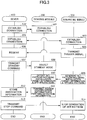
- FIG. 3 is a flowchart showing operations to be implemented in a case where a specific pattern is detected by the sensing module 200 within a predetermined waiting period.
- steps 601 and 602 connection for communication is established between the sensing-side communication device 220 of the sensing module 200 and the server-side communication device 410 of the server 400.
- steps 601 and 602 may be executed when the sensing module 200 is first connected to the communication network 500 and the power of the sensing module 200 is turned on.
- steps 603 and 604 connection for communication is established between the generating-side communication device 320 of the generating module 300 and the server-side communication device 410 of the server 400.
- steps 603 and 604 may be executed when the generating module 300 is first connected to the communication network 500 and the power of the generating module 300 is turned on.
- connection between the sensing module 200 and the server 400 may be established before establishing connection between the generating module 300 and the server 400, or vice versa.
- the trigger signal transmitting unit 361 of the generating module 300 transmits a trigger signal to the server 400 via the generating-side communication device 320 in response to an operation of the operation unit 340 .
- step 606 the standby command transmitting unit 431 of the server 400 receives the trigger signal from the generating module 300.
- the standby command transmitting unit 431 that has received the trigger signal transmits a standby command to a sensing module 200 for which association information 421 is not yet stored via the server-side communication device 410.
- a sensing module 200 for which association information 421 is already stored there may be a sensing module 200 for which association information 421 is already stored and a sensing module 200 for which association information 421 is not yet stored in the server 400.
- the server 400 keeps track of whether association information 421 for each sensing module 200 is stored in the storage device 420.
- the standby command transmitting unit 431 searches the storage device 420 to determine the sensing module 200 for which association information 421 is not yet stored. Note that in some embodiments, the standby command transmitting unit 431 may transmit the standby command to all of the sensing modules 200.
- the selecting unit 242 of the sensing module 200 that has received the standby command selects the standby mode.
- the sensor control unit 243 enables detection of a set pattern by the sensor 210. For example, assuming the first sensor 210a is configured to detect the intensity of light once per hour in the non-standby mode, and the set pattern corresponds to a light intensity variation per second, the sensor control unit 243 may control the first sensor 210a to be capable of detecting the light intensity variation per second in the standby mode.
- the signal control unit 362 controls the signal generator 310 to generate a signal including a set pattern by varying the physical quantity of light or the like.
- the set pattern may be a light intensity variation per second.
- the signal control unit 362 generates a communication frame including the specific pattern, followed by installation target information 351.
- installation target information 351 corresponding to the room selected by the operation unit 340 from among the rooms shown in the screen displayed on the display unit 330 in FIG. 2 may be included in the set pattern.
- the sensor 210 of the sensing module 200 detects the set pattern including the installation target information 351 and specific pattern.
- the first sensor 210a may detect the set pattern represented by a light intensity variation per second.
- the specific pattern is detected by the sensor 210 before a predetermined waiting period elapses.
- the pattern detection information transmitting unit 241 generates pattern detection information in response to the sensor 210 detecting the specific pattern.
- the pattern detection information transmitting unit 241 generates the pattern detection information by including the specific pattern, followed by the received installation target information 351.
- the pattern detection information transmitting unit 241 transmits the pattern detection information including the installation target information 351 and sensor identification information 231 identifying the sensor 210 that has detected the specific pattern to the server 400.
- the server 400 receives the pattern detection information and the sensor identification information 231.
- the storage control unit 432 of the server 400 stores association information 421 associating the sensor identification information 231 received from the sensing module 200 that has transmitted the pattern detection information with the installation target information 351 transmitted from the generating module 300 that has generated the specific pattern.
- the storage control unit 432 acquires the installation target information 351 from the pattern detection information. Note that the generating module 300 that has generated the specific pattern corresponds to the generating module 300 that has transmitted the trigger signal.
- step 613 in response to receiving the pattern detection information, the stop command transmitting unit 433 of the server 400 transmits a stop command to the generating module 300 that has transmitted the trigger signal.
- the signal control unit 362 receives the stop command from the server 400 and controls the signal generator 310 to stop generating the signal including the set pattern.
- the sensing module 200 that has detected the specific pattern may automatically revert to the non-standby mode or revert to the non-standby mode in response to an instruction from the server 400.
- steps 601 to 608 of FIG. 4 are identical to steps 601 to 608 of FIG. 3 .
- the generating module 300 associates each sensing module 200 with a corresponding installation target, and as such, when the generating module 300 is used to associate one sensing module 200 with an installation target, other sensing modules 200 will not detect the specific pattern included in the signal generated by the generating module 300. That is, the one sensing module 200 that is being associated with an installation target using the generating module 300 executes the operations of the sensing module 200 shown in FIG. 3 , whereas the other sensing modules 200 execute the operations of the sensing module 200 shown in FIG. 4 .
- step 620 After selecting the standby mode, when the selecting unit 242 detects in step 620 that the predetermined waiting period has elapsed without the sensor 210 detecting a specific pattern, the process proceeds to step 621 in which the selecting unit 242 selects the non-standby mode.
- step 622 when a specific pattern was not detected by the sensor 210 within the predetermined waiting period after the standby mode was selected, the non-detection information transmitting unit 244 transmits non-detection information indicating that a specific pattern was not detected to the server 400 via the sensing-side communication device 220.
- the storage control unit 432 When the storage control unit 432 receives from the sensing module 200, sensor identification information 231 and the non-detection information indicating that a specific pattern was not detected, the storage control unit 432 stores the received sensor identification information 231 and non-detection information in the storage device 420 in step 623.
- sensor identification information 231 identifying a sensor 210 and installation target information 351 identifying the installation target of the sensor 210 are stored in association with each other in the server 400, and in this way, a sensor 210 and the installation target of the sensor 210 may be accurately associated with each other. Further, a sensor 210 and the installation target of the sensor 210 can be associated with each other using a physical quantity detection function of the sensor 210, and in this way, the configuration of the sensing module 200 can be simplified as compared with a case where a function for associating a sensor with its installation target has to be added.
- a sensor 210 and the installation target of the sensor 210 can be associated with each other through relatively simple operations of generating and detecting a specific pattern, and in this way, human labor may be reduced and human operation errors due to erroneous association may be reduced as compared with a case where a human has to manually input the sensor identification information 231 and the installation target information 351.
- the installation target information 351 is included in the set pattern, and a sensing module 200 that has detected the set pattern transmits both the installation target information 351 and the sensor identification information 231.
- a sensor may be accurately associated with its installation target using a relatively simple configuration as compared with a case where the installation target information 351 and the sensor identification information 231 are separately transmitted to the server 400.
- a selection can be made between standby mode in which association information 421 is stored and non-standby mode in which association information 421 is not stored.
- the sensing module 200 can execute operations suitable for transmitting the sensor identification information 231 and the installation target information 351
- the non-standby mode the sensing module 200 can execute operations suitable for implementing its primary detection function and other operations according to the situation without regard to whether the operations are suitable for transmitting the sensor identification information 231 and the installation target information 351.
- the sensing module 200 can enable detection of the set pattern by the sensor 210.
- the sensor 210 will be capable of accurately detecting the set pattern at least when the standby mode is selected.
- the sensing module 200 when the non-standby mode is selected, the sensing module 200 disables detection of a set pattern by the sensor 210 so that detection of a set pattern may be prevented when association information 421 does not have to be stored. That is, even if the sensor 210 is required to execute special operations when the standby mode is selected, the sensor 210 may be able to execute other operations without being affected by such special operations when the non-standby mode is selected.
- a standby command may be issued so that the standby mode can be reliably selected.
- the sensing module 200 selects the standby mode based on a trigger signal. In this way, the sensing module 200 can easily detect a set pattern included in a signal generated by the generating module 300 after transmitting the trigger signal.
- the standby mode can be prevented from being selected for an unnecessarily long time in a sensing module 200 that does not receive the set pattern so that operations in the non-standby mode may not be unnecessarily hindered.
- the server 400 is explicitly notified of the sensing module 200 that has not detected a specific pattern, and in this way, the server 400 may more accurately associate a sensor 210 with the installation target of the sensor 210. With such a configuration, the server 400 can be prevented from waiting for an unnecessarily long time to receive pattern detection information from the sensing module 200.
- the server 400 when the server 400 receives the pattern detection information from the sensing module, the server 400 transmits a stop command. In this way, the generating module 300 can be prevented from generating a set pattern during a period in which generation of the set pattern is unnecessary.
- light is used to transmit the set pattern.
- the set pattern that is represented by light may be selectively transmitted to a specific sensing module 200.
- a sensor 210 and the installation target of the sensor 210 can be accurately associated with each other.
- switching between storing association information 421 and not storing association information 421 is achieved by switching between enabling and disabling detection of a set pattern by the sensor 210.
- the sensor network system 100 may switch between storing (association information 421 and not storing association information 421 using some other method.
- the pattern detection information transmitting unit 241 transmits both sensor identification information 231 and pattern detection information to the server 400 via the sensing-side communication device 220 in order to have association information 421 stored in the server 400. Also, in the first example modification, when the non-standby mode is selected by the selecting unit 242, the pattern detection information transmitting unit 241 refrains from transmitting at least one of the sensor identification information 231 and the pattern detection information to the server 400 via the sensing-side communication device 220 in order to prevent association information 421 from being stored in the server 400.
- pattern detection information in the standby mode that involves storing association information 421, pattern detection information can be reliably transmitted from the sensing module 200 to the server 400, and in the non-standby mode that does not require storing association information 421, unnecessary communication between the sensing module 200 and the server 400 may be avoided.
- the storage control unit 432 stores association information 421 in response to receiving pattern detection information from a sensing module 200 that has selected the standby mode. Also, in the second example modification, the storage control unit 432 does not store association information 421 in response to receiving pattern detection information from a sensing module 200 that has selected the non-standby mode. In the second example modification, whether a sensing module 200 has selected the standby mode or the non-standby mode may be communicated to the storage control unit 432 via the communication network 500, for example.
- the storage control unit 432 of the server 400 determines whether to store association information 421. Accordingly, the sensing module 200 may execute the same operations in the standby mode and the non-standby mode, and in this way, the configuration of the sensing module 200 may be simplified.
- FIG. 5 is a block diagram of a sensor network system 700 according to the second embodiment.
- the sensor network system 700 includes one or more sensing modules 720, one or more generating modules 730, and a server 740. Note that the following description of the sensor network system 700 according to the second embodiment focuses on features that differ from those of the sensor network system 100 according to the first embodiment ( FIG. 1 ).
- the generating module 730 includes a processor 731 that implements functions differing from those of the processor 360 of the generating module 300 according to the first embodiment ( FIG. 1 ). Specifically, a signal control unit 732 that is implemented by the processor 731 according to the present embodiment differs from the signal control unit 362 according to the first embodiment ( FIG. 1 ) in that it controls the signal generator 310 to generate a signal by varying a physical quantity to have a specific pattern without including the installation target information 351 in the signal.
- the processor 731 additionally implements an installation target information transmitting unit 733 based on a generating module program.
- the installation target information transmitting unit 733 transmits installation target information 351 to the server 400 via the generating-side communication device 320.
- the sensing module 720 includes a processor 721 that implements functions that differ from those of the sensing module 200 according to the first embodiment ( FIG. 1 ). Specifically, a pattern detection information transmitting unit 722 that is implemented by the processor 721 according to the present embodiment differs from the pattern detection information transmitting unit 241 according to the first embodiment ( FIG. 1 ) in that it generates pattern detection information that does not include installation target information 351 in response to the sensor 210 detecting a specific pattern.
- the server 740 includes a processor 741 that implements functions that differ from those of the server 400 according to the first embodiment ( FIG. 1 ).
- a storage control unit 742 of the processor 741 according to the present embodiment differs from the storage control unit 432 according to the first embodiment ( FIG. 1 ) in that it receives installation target information 351 from the installation target information transmitting unit 733 of the generating module 730 via the server-side communication device 410.
- FIG. 6 is a flowchart showing operations to be implemented in a case where a specific pattern is detected by the sensing module 720 within a predetermined waiting period. Note that operations of steps 801 to 804 of FIG. 6 are substantially identical to those of steps 601 to 604 of FIGS. 3 and 4 according to the first embodiment.
- the trigger signal transmitting unit 361 of the generating module 730 transmits a trigger signal to the server 400 via the generating-side communication device 320 in response to an operation of the operation unit 340.
- the installation target information transmitting unit 733 transmits installation target information 351 to the server 400 via the generating-side communication device 320.
- the installation target information transmitting unit 733 may transmit installation target information 351 corresponding to the room selected by the operation unit 340 from among the rooms shown in the screen displayed on the display unit 330 in FIG. 2 .
- step 806 the standby command transmitting unit 431 of the server 740 receives the trigger signal from the generating module 730. Further, the storage control unit 742 of the server 740 receives the installation target information 351 from the generating module 730.
- the standby command transmitting unit 431 that has received the trigger signal transmits a standby command to at least one sensing module 720.
- the standby command transmitting unit 431 transmits a standby command to a sensing module 720 for which association information 421 is not yet stored. Note that in some embodiments, the standby command may be transmitted to all of the sensing modules 720.
- the selecting unit 242 of the sensing module 720 selects the standby mode in step 808.
- the sensor control unit 243 enables detection of a set pattern by the sensor 210 in response to the selecting unit 242 selecting the standby mode. For example, assuming the first sensor 210a is configured to detect the intensity of light once per hour in the non-standby mode, and the set pattern corresponds to a light intensity variation per second, the sensor control unit 243 controls the first sensor 210a to be capable of detecting the light intensity variation per second in the standby mode.
- the signal control unit 732 controls the signal generator 310 to generate a signal by varying a physical quantity of light or the like in step 809.
- the set pattern may be a variation in light intensity per second. Note that the set pattern according to the present embodiment includes a specific pattern but does not include installation target information 351.
- the sensor 210 of the sensing module 720 detects the set pattern including the specific pattern.
- the first sensor 210a may detect the set pattern that is represented by a light intensity variation per second.
- the set pattern is detected by the sensor 210 before a predetermined waiting period elapses from the time the standby mode is selected by the selecting unit 242.
- the pattern detection information transmitting unit 722 generates pattern detection information in response to the sensor 210 detecting the specific pattern. Note that in the present embodiment, the pattern detection information does not include installation target information 351. In step 811, the pattern detection information transmitting unit 722 transmits the pattern detection information and sensor identification information 231 identifying the sensor 210 that has detected the specific pattern to the server 740.
- the server 740 receives the pattern detection information and the sensor identification information 231. Further, the storage control unit 742 of the server 740 stores association information 421 associating the sensor identification information 231 received from the sensing module 720 that has transmitted the pattern detection information with the installation target information 351 transmitted from the generating module 730 that has generated the specific pattern. Note that the generating module 730 that has generated the specific pattern corresponds to the generating module 730 that has transmitted the trigger signal. Also, note that that the server 740 receives the installation target information 351 via the server-side communication device 410 in step 806 as described above.
- step 813 in response to the server 740 receiving the pattern detection information, the stop command transmitting unit 433 of the server 740 transmits a stop command to the generating module 730 that has transmitted the trigger signal.
- step 814 in response to receiving the stop command from the server 740, the signal control unit 732 controls the signal generator 310 to stop generating the signal including the set pattern.
- the sensing module 720 that has detected the specific pattern may automatically revert to the non-standby mode or may revert to the non-standby mode in response to an instruction from the server 740.
- association method that is implemented in the present embodiment in the case where a specific pattern is not detected by the sensing module 720 within a predetermined waiting period may be substantially identical to the association method including steps 620 to 623 according to the first embodiment as shown in FIG. 4 .
- the generating module 730 transmits installation target information 351 directly to the server 740, and in this way, the installation target information 351 can be reliably communicated to the server 740.
- a sensor network system implements an input method for inputting installation target information 351 that differs from the sensor network system 100 according to the first embodiment as shown in FIG. 1 and the sensor network system 700 according to the second embodiment as shown in FIG. 5 .
- the signal control unit 362 controls the display unit 330 ( FIG. 1 or FIG. 5 ) to display a screen 910 as shown in FIG. 7 .
- the screen 910 displays a first input field 911, a second input field 912, a third input field 913, and a fourth input field 914 for inputting a vehicle registration number.
- a region name is input to the first input field 911
- a class number is input to the second input field 912
- a commercial discrimination code is input to the third input field 913
- a designated number is input to the fourth input field 914.
- the operation unit 340 ( FIG. 1 or FIG.
- the signal control unit 362 may accept characters as inputs to the first input field 911 through the fourth input field 914 by touch panel keyboard input, pull-down selection input, or some other input method.
- the signal control unit 362 detects that an OK button 915 has been pressed via the operation unit 340 ( FIG. 1 or FIG. 5 )
- the signal control unit 362 determines that a character string combining the characters input to the first input field 911 through the fourth input field 914 corresponds to the installation target information 351.
- the first input method according to the present embodiment may be implemented in a case where the sensing module 200 ( FIG. 1 ) or the sensing module 720 ( FIG. 5 ) is installed in a vehicle, for example.
- the signal control unit 362 controls the display unit 330 ( FIG. 1 or FIG. 5 ) to display a screen 920 as shown in FIG. 8 .
- the screen 920 includes an input field 921 that indicates a longitude and a latitude. Note that content displayed in the input field 921 may be automatically input by a GPS (global positioning system) function, manually input via the operation unit 340 ( FIG. 1 or FIG. 5 ), or input by some other method.
- the operation unit 340 ( FIG. 1 or FIG. 5 ) may accept characters as inputs to the input field 921 by touch panel keyboard input, pull-down selection input, or some other input method.
- the signal control unit 362 detects that an OK button 922 has been pressed via the operation unit 340 ( FIG. 1 or FIG. 5 )
- the signal control unit 362 determines that a character string combining the characters input to the input field 921 corresponds to the target information 351.
- the second input method according to the present embodiment may be implemented in a case where the sensing module 200 ( FIG. 1 ) or the sensing module 720 ( FIG. 5 ) is installed in a field, for example.
- a sensor network system 930 according to a fourth embodiment as shown in FIG. 9 includes a generating module 931, a sensing module 932, and a server 933.
- the generating module 931, the sensing module 932, and the server 933 are configured to communication with each other via a communication network 934 that is substantially identical to the communication network 500 according to the first embodiment.
- the generating module 931 is attached to a bib 941 that is worn by a person that engages in sports.
- the generating module 931 may have a configuration substantially identical to that of the generating module 300 according to the first embodiment ( FIG. 1 ) or the generating module 730 ( FIG. 5 ) according to the second embodiment.
- the generating module 931 according to the present embodiment is not a smartphone but is instead a lightweight device that stores a number that uniquely identifies each specific bib 941 from among a plurality of bibs 941 as installation target information 351.
- the sensing module 932 is attached to a wristband 942 to be worn on the wrist when a person engages in sports.
- the sensing module 932 may have a configuration substantially identical to that of the sensing module 200 according to the first embodiment ( FIG. 1 ) or the sensing module 720 according to the second embodiment ( FIG. 5 ).
- the sensing module 932 according to the present embodiment includes sensors 210 for measuring a physical quantity associated with biological information, such as body temperature, the physical quantity of light, and other physical quantities.
- the sensing module 932 stores sensor identification information 231 uniquely identifying each wristbands 942 from among a plurality of wristbands 942.
- the server 933 is managed by an administrator of a sports event.
- the server 933 may have a configuration substantially identical to that of the server 400 according to the first embodiment ( FIG. 1 ) or the server 740 according to the second embodiment ( FIG. 5 ).
- the association method according to the first embodiment or the second embodiment may be executed in the sensor network system 930 according to the present embodiment so that association information associating installation target information 351 identifying a bib 941 with sensor identification information 231 identifying a wristband 942 may be stored in the server 933.
- association information may be set up through simple procedures as compared with the case where a wristband and a bib are manually associated with each other. Also, because the sensing module 932 for measuring biological information that is installed in the wristband 942 is used for associating the wristband 942 with the corresponding bib 941, the association information may be set up using a simple configuration as compared with a case where a dedicated sensing module is separately provided.
- an association between a wristband 942 and a bib 941 may be newly set up through simple operations. Also, in a case where a plurality of types of wristbands 942 provided with sensors 210 for different applications are prepared, altering the association between a bib 941 and a wristband 942 may be easier as compared with a case where the association is altered by a person.
- the present invention may be applied to a sensor network system in which a plurality of sensors are used in a variety of environments.
Landscapes
- Engineering & Computer Science (AREA)
- Computer Networks & Wireless Communication (AREA)
- Signal Processing (AREA)
- Health & Medical Sciences (AREA)
- Computing Systems (AREA)
- General Health & Medical Sciences (AREA)
- Medical Informatics (AREA)
- Physics & Mathematics (AREA)
- General Physics & Mathematics (AREA)
- Arrangements For Transmission Of Measured Signals (AREA)
- Telephonic Communication Services (AREA)
Abstract
Description
- The present invention relates to a sensor network system, a sensing module, a server, and an association method.
- Sensor network systems including a plurality of sensors installed at various positions to acquire data such as the temperature from each sensor are known. Such sensor network systems need to know the position at which data is acquired by each sensor. For example, Patent Document 1 describes a sensor network system in which sensors are able to communicate with each other and data of each sensor is communicated to a parent apparatus through multi-hop transmission (relaying) by multiple sensors. The parent apparatus uses the number of hops to estimate the approximate position of a sensor.
- Patent Document 1: International
PCT Patent Application Publication No. WO 2014/013578 - However, according to the technique disclosed in Patent Document 1, a sensor and the position of the sensor cannot be associated with each other unless the sensor is used for multi-hop data transmission. Further, according to the technique of Patent Document 1, because the number of hops is used, the position of a sensor can only be estimated, and as such, the sensor and the position of the sensor cannot be accurately associated with each other. Further, because the position of an antenna associated with a sensor is regarded as the position of the sensor, the position of the sensor cannot be accurately determined in a case where the antenna and the sensor are separated from each other. Also, a moving objet having a sensor attached thereto cannot be identified. In other words, a sensor cannot be accurately associated with a sensor position or a sensor installation target, such as a moving object to which the sensor is attached, for example.
- The present invention has been conceived in view of the above-described problems of the related art, and an object of the present invention is to provide a sensor network system, a sensing module, a server, and an association method for accurately associating a sensor with a sensor installation target (e.g., sensor position, moving object to which the sensor is attached).
- According to one embodiment of the present invention, a sensor network system is provided that includes a server, one or more sensing modules including one or more sensors configured to detect a physical quantity, and at least one generating module. The generating module includes a signal generator configured to generate a signal by varying the physical quantity to be detected by a sensor of the one or more sensors included in a sensing module of the one or more sensing modules. The generating module is further configured to communicate installation target information identifying an installation target of the sensor to the server. The generating module further includes a signal control unit configured to control the signal generator to generate the signal that includes a set pattern including a specific pattern. The sensing module further includes a sensing-side communication device configured to communicate with the server, and a pattern detection information transmitting unit configured to transmit to the server, via the sensing-side communication device, pattern detection information generated in response to the sensor detecting the specific pattern and sensor identification information identifying the sensor that has detected the specific pattern. The server further includes a server-side communication device configured to communicate with the sensing-side communication device, and a storage control unit configured to store association information associating the sensor identification information received by the server-side communication device from the sensing module that has transmitted the pattern detection information with the installation target information transmitted from the generating module that has generated the specific pattern.
- According to an aspect of the above embodiment, sensor identification information identifying a sensor and installation target information identifying the installation target of the sensor are stored in association with each other in the server, and in this way, a sensor and the installation target of the sensor may be accurately associated with each other. Further, a sensor and the installation target of the sensor can be associated with each other using a physical quantity detection function of the sensor, and in this way, the configuration of the sensing module can be simplified as compared with a case where a function for associating a sensor with its installation target has to be added. Also, a sensor and the installation target of the sensor can be associated with each other through relatively simple operations of generating and detecting a specific pattern, and in this way, human labor may be reduced and human operation errors due to erroneous association may be reduced as compared with a case where a human has to manually input the sensor identification information and the installation target information.
- In one preferred embodiment of the sensor network system according to the present invention, the signal control unit controls the signal generator to generate the set pattern that further includes the installation target information, the pattern detection information transmitting unit generates the pattern detection information that includes the installation target information included in the set pattern, and the storage control unit acquires the installation target information from the pattern detection information.
- According to an aspect of the above embodiment, installation target information is included in the set pattern, and the sensing module that has detected the set pattern communicates both the installation target information and the sensor identification information to the server. In this way, association of a sensor with its installation target may be more reliably performed with a simple configuration as compared with a case where the installation target information and the sensor identification information are separately communicated to the server.
- In one preferred embodiment of the sensor network system according to the present invention, the generating module further includes a generating-side communication device configured to communicate with the server, and an installation target information transmitting unit configured to transmit the installation target information to the server via the generating-side communication device.
- According to an aspect of the above embodiment, the generating module communicates the installation target information directly to the server, and in this way, the installation target information may be reliably communicated.
- In one preferred embodiment of the sensor network system according to the present invention, the sensing module further includes a selecting unit configured to select at least one operation mode from among a plurality of operation modes including a standby mode and a non-standby mode, the storage control unit stores the association information when the standby mode is selected by the selecting unit, and the storage control unit does not store the association information when the non-standby mode is selected by the selecting unit.
- According to an aspect of the above embodiment, a selection can be made between the standby mode in which association information is stored and the non-standby mode in which association information is not stored. In this way, when the standby mode is selected, the sensing module can execute operations suitable for communicating sensor identification information and installation target information, whereas when the non-standby mode is selected, the sensing module can execute operations suitable for implementing its primary detection function and other operations according to the situation without regard to whether the operations are suitable for communicating sensor identification information and installation target information.
- In one preferred embodiment of the sensor network system according to the present invention, the sensing module further includes a sensor control unit, and the sensor control unit enables detection of the set pattern by the sensor in response to the standby mode being selected by the selecting unit.
- According to an aspect of the above embodiment, the sensing module enables detection of a set pattern by the sensor when the standby mode is selected. In this way, even if the sensor is not capable of detecting a set pattern when the non-standby mode is selected, the sensor can still reliable detect a set pattern at least when the standby mode is selected.
- In one preferred embodiment of the sensor network system according to the present invention, the sensor control unit disables detection of the set pattern by the sensor in response to the non-standby mode being selected by the selecting unit.
- According to an aspect of the above embodiment, the sensing module disables detection of a set pattern by the sensor when the non-standby mode is selected. In this way, pattern detection can be prevented when association information does not have to be stored. Even if the sensor may have to perform special operations when the standby mode is selected, the sensor can perform other operations without being influenced by such special operations when the non-standby mode is selected.
- In one preferred embodiment of the sensor network system according to the present invention, the pattern detection information transmitting unit transmits both the sensor identification information and the pattern detection information to the server via the sensing-side communication device when the standby mode is selected by the selecting unit, and the pattern detection information transmitting unit does not transmit at least one of the sensor identification information and the pattern detection information to the server via the sensing-side communication device when the non-standby mode is selected by the selecting unit.
- According to an aspect of the above embodiment, in standby mode that involves storing association information, pattern detection information can be reliably communicated from the sensing module to the server, and in non-standby mode that does not require storing association information, unnecessary communication between the sensing module and the server may be prevented.
- In one preferred embodiment of the sensor network system according to the present invention, the storage control unit stores the association information in response to receiving the pattern detection information from the sensing module that has the standby mode selected, and the storage control unit does not store the association information in response to receiving the pattern detection information from the sensing module that has the non-standby mode selected.
- According to an aspect of the above embodiment, the storage control unit of the server determines whether association information is to be stored. In this way, the sensing module can perform the same operations in standby mode and non-standby mode such that the configuration of the sensing module can be simplified.
- In one preferred embodiment of the sensor network system according to the present invention, the server further includes a standby command transmitting unit configured to transmit a standby command to at least one sensing module of the one or more sensing modules via the server-side communication device, and the selecting unit selects the standby mode in response to the sensing-side communication device receiving the standby command.
- According to an aspect of the above embodiment, when association information needs to be stored, a standby command may be issued so that the standby mode can be reliably selected.
- In one preferred embodiment of the sensor network system according to the present invention, the generating module further includes a trigger signal transmitting unit configured to transmit a trigger signal via the generating-side communication device, the standby command transmitting unit transmits the standby command in response to the server-side communication device receiving the trigger signal, and the signal control unit controls the signal generator to generate the signal including the set pattern during a period including a time after the trigger signal is transmitted.
- According to an aspect of the above embodiment, the sensing module selects the standby mode based on a trigger signal. In this way, the sensing module can easily detect a set pattern included in a signal that is generated by the generating module after transmitting the trigger signal.
- In one preferred embodiment of the sensor network system according to the present invention, the selecting unit selects the non-standby mode after a predetermined waiting period elapses from a time the standby mode is selected.
- According to an aspect of the above embodiment, a sensing module that is not receiving a set pattern can be prevented from operating in the standby mode for an unnecessarily long time so that operations in the non-standby mode may not be unnecessarily hindered.
- In one preferred embodiment of the sensor network system according to the present invention, the sensing module further includes a non-detection information transmitting unit configured to transmit, via the sensing-side communication device, non-detection information indicating that the specific pattern has not been detected when the sensor does not detect the specific pattern during a predetermined period after the standby mode is selected.
- According to an aspect of the above embodiment, the server may be explicitly notified of the sensing module that has not detected a specific pattern, and in this way, a sensor and the installation target of the sensor may be more accurately associated with each other. Also, according to an aspect of the above embodiment, the server may be prevented from having to wait for an unnecessarily long time to receive pattern detection information from the sensing module.
- In one preferred embodiment of the sensor network system according to the present invention, the server further includes a stop command transmitting unit configured to transmit a stop command via the server-side communication device in response to receiving the pattern detection information, and the signal control unit controls the signal generator to stop generation of the signal including the set pattern in response to receiving the stop command via the generating-side communication device.
- According to an aspect of the above embodiment, when the server receives pattern detection information, the server transmits a stop command. In this way, the generating module may be prevented from generating a set pattern for an unnecessarily long period.
- In one preferred embodiment of the sensor network system according to the present invention, the physical quantity is an intensity of light.
- According to an aspect of the above embodiment, even in an environment including a plurality of sensing modules, a set pattern represented by a variation in light intensity may be selectively transmitted to a specific sensing module from among the plurality of sensing modules.
- According to another embodiment of the present invention, an association method is provided that is to be implemented by a sensor network system including one or more sensing modules including one or more sensors configured to detect a physical quantity, at least one generating module including a signal generator configured to generate a signal by varying the physical quantity to be detected by a sensing module of the one or more sensors included in a sensing module of the one or more sensing modules, the generating module being configured to communicate installation target information identifying an installation target of the sensor to a server, and the server that is capable of communicating with the sensing module and the generating module. The association method includes the generating module controlling the signal generator to generate the signal that includes a set pattern including a specific pattern; the sensing module transmitting to the server, pattern detection information generated in response to the sensor detecting the specific pattern and sensor identification information identifying the sensor that has detected the specific pattern; and the server storing association information associating the sensor identification information received from the sensing module that has transmitted the pattern detection information with the installation target information communicated from the generating module that has generated specific pattern.
- According to another embodiment of the present invention, a sensing module is provided that is used in a sensor network system including a server configured to store association information associating sensor identification information identifying a sensor that has detected a specific pattern represented by a variation in a physical quantity with installation target information identifying an installation target of the sensor, the installation target information being communicated from a generating module that has generated a signal including a set pattern that includes the specific pattern. The sensing module includes the sensor that is configured to detect the physical quantity; a sensing-side communication device configured to communicate with the server; and a pattern detection information transmitting unit configured to transmit to the server, via the sensing-side communication device, the pattern detection information generated in response to the sensor detecting the specific pattern and the sensor identification information identifying the sensor that has detected the specific pattern.
- According to another embodiment of the present invention, a server is provided that is used in a sensor network system including one or more sensing modules including one or more sensors configured to detect a physical quantity and at least one generating module configured to generate a signal that includes a set pattern including a specific pattern by varying the physical quantity to be detected by a sensor of the one or more sensors included in a sensing module of the one or more sensing modules, the generating module further being configured to communicate installation target information identifying an installation target of the sensor. The server includes a server-side communication device configured to receive from the sensing module, pattern detection information generated in response to the sensor detecting the specific pattern and sensor identification information identifying the sensor that has detected the specific pattern; and a storage control unit configured to store association information associating the sensor identification information received by the server-side communication device from the sensing module that has transmitted the pattern detection information with the installation target information communicated from the generating module that has generated the specific pattern.
- According to an aspect of the present invention, a sensor and an installation target of the sensor can be accurately associated with each other.
-
-
FIG. 1 is a configuration diagram of a sensor network system according to a first embodiment of the present invention; -
FIG. 2 is a diagram showing an example display of a display unit of the sensor network system; -
FIG. 3 is a flowchart showing operations of the sensor network system according to the first embodiment when a specific pattern is detected; -
FIG. 4 is a flowchart showing operations of the sensor network system according to the first embodiment when a specific pattern is not detected; -
FIG. 5 is a configuration diagram of a sensor network system according to a second embodiment of the present invention; -
FIG. 6 is a flowchart showing operations to be implemented by the network system according to the second embodiment when a specific pattern is detected; -
FIG. 7 is a diagram showing an example screen displayed for implementing a first input method according to a third embodiment of the present invention; -
FIG. 8 is a diagram showing an example screen displayed for implementing a second input method according to the third embodiment; and -
FIG. 9 is a configuration diagram of a sensor network system according to a fourth embodiment of the present invention. - In the following, a sensor network system according to a first embodiment of the present invention will be described.
FIG. 1 is a block diagram showing an example configuration of asensor network system 100 according to the present embodiment. Thesensor network system 100 includes one ormore sensing modules 200, one ormore generating modules 300, and aserver 400. - The
server 400 managesassociation information 421. Theassociation information 421 is information associating a sensor 210 included in thesensing module 200 with a corresponding installation target of the sensor 210. Theserver 400 manages detections obtained by the sensor 210 based on theassociation information 421. Note that the present description mainly illustrates embodiments of a system, an apparatus, and a method relating to storing association information associating sensors 210 with their respective installation targets in theserver 400. - The installation target of the sensor 210 may be a position represented by latitude and longitude, or some other item, such as a room in which the sensor 210 is installed, a position within a room in which the sensor 210 is installed, a factory assembly line in which the sensor 210 is installed, a part of a robot in which the sensor 210 is installed, a moving body in which the sensor 210 is installed, a person that is carrying the sensor 210, or a detection target of the sensor 210 (especially when the sensor 210 and the detection target are separated from each other), for example. Note, however, that the installation target is not limited to the above examples. The installation target is identified by
installation target information 351, which is described below. For example, by defining differentinstallation target information 351 for each room, theserver 400 may be able to recognize the specific room in which the sensor 210 is to detect a physical quantity. Note that the association between theinstallation target information 351 and the installation target may be pre-set in theserver 400, set up as desired by an operator, or set up in some other manner, for example. - In the following, an example configuration of the
sensor network system 100 will be briefly described. In the present embodiment, asingle sensing module 200 includes a plurality of sensors 210. An operator sequentially places onesensing module 200 in each of a plurality of rooms. As described below, eachsensing module 200 has afirst sensor 210a that detects the brightness of a room and asecond sensor 210b that detects the temperature of a room. The operator carries onegenerating module 300. When the operator installs asensing module 200 in each room, the operator transmits light from thegenerating module 300 to thesensor 210a of thesensing module 200 to register theassociation information 421 in theserver 400. Note that in some embodiments, a plurality of operators may each carry onegenerating module 300, for example. - As shown in
FIG. 1 , thesensing module 200 includes thefirst sensor 210a, thesecond sensor 210b, a sensing-side communication device 220, astorage device 230, and aprocessor 240. Note that in the present description, the first sensor 201a and thesecond sensor 210b may generically be referred to as "sensor 210". Further, a plurality of sensors 210 of a plurality ofsensing modules 200 included in thesensor network system 100 may generically be referred to as "sensors 210". Also, the above components of thesensing module 200 may be physically separable from each other, for example. - The
first sensor 210a detects light as a physical quantity. Thesecond sensor 210b detects the temperature as a physical quantity. Note that in some embodiments, thesensing module 200 may include three or more sensors 210. For example, thesensing module 200 may include a plurality of sensors 210 that detect the same physical quantity, or thesensing module 200 may include a plurality of sensors 210 that detect different physical quantities. The physical quantity to be detected by the sensor 210 is not limited to the examples described in the present embodiment. Examples of physical quantities to be detected include, but are not limited to, temperature, humidity, moisture, heat, density, viscosity, flow rate, pressure, acceleration, vibration, strain, light, magnetism, displacement, position, and rotation. - The sensing-
side communication device 220 communicates with a server-side communication device 410 of the server 400 (described below) via acommunication network 500. Thecommunication network 500 may be a wireless network, a wired network, or a combination thereof, for example. - The
storage device 230 stores a sensing module program to be executed by thesensing module 200. The sensing module program, when read and executed by theprocessor 240, causes theprocessor 240 to implement various functions including a function of performing a part of an association method according to the present embodiment. When theprocessor 240 implements various functions, thestorage device 230 is controlled by theprocessor 240 to store necessary information. Thestorage device 230 is a non-transitory tangible storage medium. Thestorage device 230 includes a ROM (read only memory) and a RAM (random access memory). Thestorage device 230 may be a volatile storage medium or a non-volatile storage medium. Also, thestorage device 230 may be a removable storage medium or a non-removable storage medium. - The
storage device 230 further storessensor identification information 231. Thesensor identification information 231 is information identifying each of a plurality of sensors 210 included in thesensor network system 100. - The
processor 240 reads and executes the sensing module program stored in thestorage device 230 to implement functions of a pattern detectioninformation transmitting unit 241, a selectingunit 242, asensor control unit 243, and a non-detectioninformation transmitting unit 244. Note that although a general purpose computer is used as theprocessor 240 in the present embodiment, theprocessor 240 may also be an application specific integrated circuit (ASIC) or some other circuit that is capable of implementing the functions described in the present embodiment. - The pattern detection
information transmitting unit 241 generates pattern detection information in response to the sensor 210 detecting a specific pattern as described below. The specific pattern is a signal indicating the start of operations for registeringassociation information 421. The pattern detection information is a signal indicating that a specific pattern has been detected. The pattern detectioninformation transmitting unit 241 generates the pattern detection information in response to detecting the specific pattern and includesinstallation target information 351 in the pattern detection information. As described below, thegenerating module 300 generates a signal including a set pattern that includes theinstallation target information 351 and the specific pattern. Thegenerating module 300 transmits the specific pattern included in the set pattern, followed by theinstallation target information 351. - The pattern detection
information transmitting unit 241 transmits to theserver 400, via the sensing-side communication device 220, the pattern detection information including theinstallation target information 351 and thesensor identification information 231 identifying the sensor 210 that has detected the specific pattern. For example, when a specific pattern that is communicated by light is detected by thefirst sensor 210a of asensing module 200,sensor identification information 231 identifying the sensors 210 included in thesensing module 200 from among a plurality ofsensing modules 200 is transmitted to theserver 400. Note that the samesensor identification information 231 may be assigned to the plurality of sensors 210 included in onesensing module 200, or differentsensor identification information 231 may be assigned to each of the plurality of sensors 210. Also, each of the plurality of sensors 210 included in onesensing module 200 may be associated with the same installation target or a different installation target. In the present embodiment, the samesensor identification information 231 is assigned to the plurality of sensors 210 included in onesensing module 200. As such, the plurality of sensors 210 included in onesensing module 200 are all associated with the same installation target. - Note that in another embodiment, the pattern detection
information transmitting unit 241 may transmit all detections obtained by the sensor 210 to theserver 400 without determining whether a specific pattern has been detected. In such other embodiment, detection of a specific pattern among the detections corresponds to the pattern detection information. In such other embodiment, theserver 400 extracts from all the detections of the sensor 210, the detection corresponding to the pattern detection information generated in response to the sensor 210 detecting the specific pattern. - The selecting
unit 242 selects at least one of a plurality of operation modes. The plurality of operation modes include a standby mode and a non-standby mode. Thesensor network system 100 is configured such that when the standby mode is selected by the selectingunit 242, astorage control unit 432 of theserver 400stores association information 421 as described below. Further, thesensor network system 100 is configured such that when the non-standby mode is selected by the selectingunit 242, thestorage control unit 432 of theserver 400 does not storeassociation information 421 as described below. Examples of the non-standby mode may include an operation mode to stop detection and an operation mode for normal detection. In the present embodiment, the non-standby mode collectively refers to states in which the standby mode is not selected. - The selecting
unit 242 selects the standby mode when the sensing-side communication device 220 receives a standby command from theserver 400. Then, when a predetermined waiting period elapses from the time the selectingunit 242 selects the standby mode, the selectingunit 242 selects the non-standby mode. - The
sensor control unit 243 enables detection of a set pattern by the sensor 210 in response to the selectingunit 242 selecting the standby mode. Thesensor control unit 243 disables detection of a set pattern by the sensor 210 in response to the selectingunit 242 selecting the non-standby mode. For example, it is assumed below that in the non-standby mode, thefirst sensor 210a detects the intensity of light once per hour, and the set pattern corresponds to a light intensity variation per second. In this case, in the standby mode, thesensor control unit 243 controls thefirst sensor 210a to be capable of detecting the light intensity variation per second, and in the non-standby mode, thesensor control unit 243 controls thefirst sensor 210a to detect the intensity of light once per hour. In this way, for example, even if energy consumption of thefirst sensor 210a may be relatively high in the standby mode, when a set pattern does not have to be detected, the non-standby mode with lower energy consumption may be selected to reduce energy consumption. - After the standby mode is selected, if a specific pattern is not detected by the sensor 210 within a predetermined waiting period, the non-detection
information transmitting unit 244 transmits to theserver 400, via the sensing-side communication device 220,sensor identification information 231 identifying the sensor 210 that did not detect a specific pattern and non-detection information indicating that the specific pattern has not been detected. Based on the non-detection information, theserver 400 may be explicitly notified that the sensor 210 has not detected a specific pattern. - The
generating module 300 includes asignal generator 310, a generating-side communication device 320, adisplay unit 330, anoperation unit 340, astorage device 350, and aprocessor 360. Thegenerating module 300 according to the present embodiment is a smart phone. Note that the above components of thegenerating module 300 may be physically separated from each other, for example. - The
signal generator 310 generates a signal by varying a physical quantity to be detected by at least one sensor 210 of at least onesensing module 200. Thesignal generator 310 in the present embodiment is a light source that generates light to be detected by thefirst sensor 210a. The light source may be a built-in flashlight, an external light emitting diode, or a built-in display, for example. In the case where thesignal generator 310 is configured to generate a signal using a physical quantity other than light, thesignal generator 310 may be a heater, a cooler, a humidifier, a dehumidifier, a pressure pump, a vibration generator, or an electromagnets, for example. - The generating-
side communication device 320 communicates with the server-side communication device 410 of the server 400 (described below) via thecommunication network 500. Thecommunication network 500 may be a wireless network, a wired network, or a combination thereof. - The
display unit 330 presents text, images, video, and the like to the operator. Thedisplay unit 330 may be a liquid crystal display, for example. Theoperation unit 340 receives an input from the operator. For example, theoperation unit 340 may be an electrostatic capacitive input device, a mechanical button, or a mechanical slider. In the present embodiment, thedisplay unit 330 and theoperation unit 340 are integrated to constitute a capacitive touch panel display. -
FIG. 2 shows an example screen display of thedisplay unit 330. A layout drawing of actual rooms A to L is displayed on thedisplay unit 330. When the operator touches one of the rooms A to L displayed on thedisplay unit 330, theoperation unit 340 detects the room that has been touched by the operator. - The
storage device 350 shown inFIG. 1 stores theinstallation target information 351 and a generating module program to be executed by thegenerating module 300. The generating module program, when read and executed by theprocessor 360, causes theprocessor 360 to implement various functions including a function of performing a part of an association method according to the present embodiment. When theprocessor 360 executes various functions, thestorage device 350 is controlled by theprocessor 360 to store necessary information. Thestorage device 350 is a non-transitory tangible storage medium. Thestorage device 350 includes a ROM and a RAM. Thestorage device 350 may be a volatile storage medium or a non-volatile storage medium. Also, thestorage device 350 may be a removable storage medium or a non-removable storage medium. - The
processor 360 reads and executes the generating module program stored in thestorage device 350 to implement functions of a triggersignal transmitting unit 361 and asignal control unit 362. Note that although theprocessor 360 in the present embodiment is a general-purpose computer, theprocessor 360 may also be an application specific integrated circuit (ASIC) or some other circuit that is capable of implementing the function of the embodiments described below. - The trigger
signal transmitting unit 361 transmits a trigger signal to theserver 400 via the generating-side communication device 320. The trigger signal indicates the start of operations for generating a signal including a set pattern as described below. In the present embodiment, when theoperation unit 340 detects the pressing of a button displayed on thedisplay unit 330, the triggersignal transmitting unit 361 transmits a trigger signal. Note that a trigger signal may be transmitted at some other timing, such as when the power of thegenerating module 300 is turned on, for example. - The
signal control unit 362 controls thesignal generator 310 to generate a signal including a set pattern by varying a physical quantity. The set pattern includes a specific pattern andinstallation target information 351. In the present embodiment where thesignal generator 310 is a light source, the set pattern corresponds to a light intensity variation. The set pattern may be an analog signal or a digital signal. Thesignal control unit 362 controls thedisplay unit 330 to display the screen ofFIG. 2 and receives notification of the room that has been touched by the operator from theoperation unit 340. Thesignal control unit 362 generates a communication frame including a specific pattern, followed byinstallation target information 351 corresponding to the room that has been touched. That is, thegenerating module 300 transmits theinstallation target information 351 identifying the installation target of the sensor 210 after the specific pattern. Note that the method of selecting theinstallation target information 351 is not limited to the above-described example. - The
signal control unit 362 controls thesignal generator 310 to generate a signal including a set pattern during a period including a time after the trigger signal has been transmitted by the triggersignal transmitting unit 361. For example, thesignal control unit 362 may start generation of a signal including a set pattern immediately after a trigger signal is transmitted. Thesignal control unit 362 controls thesignal generator 310 to stop generating the signal including the set pattern after receiving a stop command from theserver 400 via the generating-side communication device 320. - Note that although the
generating module 300 in the present embodiment corresponds to a smart phone, thegenerating module 300 may also be some other device. Also, onegenerating module 300 may be configured to enable selection ofinstallation target information 351 of an installation target from amonginstallation target information 351 of a plurality of installation targets as in the present embodiment, or alternatively, onegenerating module 300 may be configured to storeinstallation target information 351 of only one installation target, for example. - The
server 400 includes the server-side communication device 410, astorage device 420, and aprocessor 430. - The server-
side communication device 410 communicates with the sensing-side communication device 220 of thesensing module 200 and the generating-side communication device 320 of thegenerating module 300 via thecommunication network 500. Thecommunication network 500 may be a wireless network, a wired network, or a combination thereof. - The
storage device 420stores association information 421 and a server program to be executed by theserver 400. The server program, when read and executed by theprocessor 430, causes theprocessor 430 to implement various functions including a function of performing a part of an association method according to the present embodiment. When theprocessor 430 executes various functions, thestorage device 420 is controlled by theprocessor 430 to store necessary information. - The
processor 430 reads and executes the server program stored in thestorage device 420 to implement functions of a standbycommand transmitting unit 431, astorage control unit 432, and a stopcommand transmitting unit 433. - The standby
command transmitting unit 431 transmits a standby command to at least onesensing module 200 via the server-side communication device 410 in response to receiving a trigger signal from thegenerating module 300 via the server-side communication device 410. In the present embodiment, it is assumed that thesensing module 200 corresponding to the transmission destination of the standby command is asensing module 200 including a sensor 210 for whichassociation information 421 has not yet been stored. Thesensing module 200 corresponding to the transmission destination of the standby command may alternatively be all of thesensing modules 200 included in thesensor network system 100 or one ormore sensing modules 200 selected based on some other criteria, for example. - The
storage control unit 432 stores in thestorage device 420,association information 421 associating thesensor identification information 231 received by the server-side communication device 410 from thesensing module 200 that has transmitted the pattern detection information with theinstallation target information 351 transmitted from thegenerating module 300 that has generated the specific pattern to be detected by thesensing module 200. Thestorage control unit 432 acquires theinstallation target information 351 from the pattern detection information. Theassociation information 421 indicates an association betweensensor identification information 231 andinstallation target information 351; i.e., an association between the ID of a sensor 210 and the installation target of the sensor 210. For example, the installation position of a sensor 210 with a given ID can be determined based on theassociation information 421. - When the
storage control unit 432 receives from asensing module 200,sensor identification information 231 and non-detection information indicating that a set pattern has not been detected, thestorage control unit 432 stores the receivedsensor identification information 231 and non-detection information in thestorage device 420. - The stop
command transmitting unit 433 transmits a stop command via the server-side communication device 410 in response to receiving the pattern detection information. The transmission destination of the stop command is thegenerating module 300 that has transmitted the trigger signal. - In the following, an association method for associating a sensor 210 with the installation target of the sensor 210 will be described with reference to
FIG. 3. FIG. 3 is a flowchart showing operations to be implemented in a case where a specific pattern is detected by thesensing module 200 within a predetermined waiting period. - In
steps side communication device 220 of thesensing module 200 and the server-side communication device 410 of theserver 400. For example, steps 601 and 602 may be executed when thesensing module 200 is first connected to thecommunication network 500 and the power of thesensing module 200 is turned on. - In
steps side communication device 320 of thegenerating module 300 and the server-side communication device 410 of theserver 400. For example, steps 603 and 604 may be executed when thegenerating module 300 is first connected to thecommunication network 500 and the power of thegenerating module 300 is turned on. - Note that connection between the
sensing module 200 and theserver 400 may be established before establishing connection between the generatingmodule 300 and theserver 400, or vice versa. - After connection is established between the generating
module 300 and theserver 400, instep 605, the triggersignal transmitting unit 361 of thegenerating module 300 transmits a trigger signal to theserver 400 via the generating-side communication device 320 in response to an operation of theoperation unit 340 . - Then, in
step 606, the standbycommand transmitting unit 431 of theserver 400 receives the trigger signal from thegenerating module 300. - In
step 607, the standbycommand transmitting unit 431 that has received the trigger signal transmits a standby command to asensing module 200 for whichassociation information 421 is not yet stored via the server-side communication device 410. Note that from among one ormore sensing modules 200 that are connected to thecommunication network 500, there may be asensing module 200 for whichassociation information 421 is already stored and asensing module 200 for whichassociation information 421 is not yet stored in theserver 400. Theserver 400 keeps track of whetherassociation information 421 for eachsensing module 200 is stored in thestorage device 420. The standbycommand transmitting unit 431 searches thestorage device 420 to determine thesensing module 200 for whichassociation information 421 is not yet stored. Note that in some embodiments, the standbycommand transmitting unit 431 may transmit the standby command to all of thesensing modules 200. - After connection is established between the
sensing module 200 and theserver 400, instep 608, the selectingunit 242 of thesensing module 200 that has received the standby command selects the standby mode. In response to the selectingunit 242 selecting the standby mode, thesensor control unit 243 enables detection of a set pattern by the sensor 210. For example, assuming thefirst sensor 210a is configured to detect the intensity of light once per hour in the non-standby mode, and the set pattern corresponds to a light intensity variation per second, thesensor control unit 243 may control thefirst sensor 210a to be capable of detecting the light intensity variation per second in the standby mode. - After the trigger
signal transmitting unit 361 of thegenerating module 300 transmits a trigger signal, instep 609, thesignal control unit 362 controls thesignal generator 310 to generate a signal including a set pattern by varying the physical quantity of light or the like. For example, the set pattern may be a light intensity variation per second. Thesignal control unit 362 generates a communication frame including the specific pattern, followed byinstallation target information 351. For example,installation target information 351 corresponding to the room selected by theoperation unit 340 from among the rooms shown in the screen displayed on thedisplay unit 330 inFIG. 2 may be included in the set pattern. - In
step 610, the sensor 210 of thesensing module 200 detects the set pattern including theinstallation target information 351 and specific pattern. For example, thefirst sensor 210a may detect the set pattern represented by a light intensity variation per second. In the example process flow ofFIG. 3 , after the selectingunit 242 selects the standby mode, the specific pattern is detected by the sensor 210 before a predetermined waiting period elapses. - The pattern detection
information transmitting unit 241 generates pattern detection information in response to the sensor 210 detecting the specific pattern. The pattern detectioninformation transmitting unit 241 generates the pattern detection information by including the specific pattern, followed by the receivedinstallation target information 351. Instep 611, the pattern detectioninformation transmitting unit 241 transmits the pattern detection information including theinstallation target information 351 andsensor identification information 231 identifying the sensor 210 that has detected the specific pattern to theserver 400. - Then, in
step 612, theserver 400 receives the pattern detection information and thesensor identification information 231. Thestorage control unit 432 of theserver 400stores association information 421 associating thesensor identification information 231 received from thesensing module 200 that has transmitted the pattern detection information with theinstallation target information 351 transmitted from thegenerating module 300 that has generated the specific pattern. Thestorage control unit 432 acquires theinstallation target information 351 from the pattern detection information. Note that thegenerating module 300 that has generated the specific pattern corresponds to thegenerating module 300 that has transmitted the trigger signal. - In
step 613, in response to receiving the pattern detection information, the stopcommand transmitting unit 433 of theserver 400 transmits a stop command to thegenerating module 300 that has transmitted the trigger signal. - In
step 614, thesignal control unit 362 receives the stop command from theserver 400 and controls thesignal generator 310 to stop generating the signal including the set pattern. Thesensing module 200 that has detected the specific pattern may automatically revert to the non-standby mode or revert to the non-standby mode in response to an instruction from theserver 400. - In the following, an association method for associating a sensor 210 with the installation target of the sensor 210 in a case where a specific pattern is not detected by the
sensing module 200 within a predetermined waiting period will be described with reference toFIG. 4 . Note that steps 601 to 608 ofFIG. 4 are identical tosteps 601 to 608 ofFIG. 3 . - The
generating module 300 associates eachsensing module 200 with a corresponding installation target, and as such, when thegenerating module 300 is used to associate onesensing module 200 with an installation target,other sensing modules 200 will not detect the specific pattern included in the signal generated by thegenerating module 300. That is, the onesensing module 200 that is being associated with an installation target using thegenerating module 300 executes the operations of thesensing module 200 shown inFIG. 3 , whereas theother sensing modules 200 execute the operations of thesensing module 200 shown inFIG. 4 . - After selecting the standby mode, when the selecting
unit 242 detects instep 620 that the predetermined waiting period has elapsed without the sensor 210 detecting a specific pattern, the process proceeds to step 621 in which the selectingunit 242 selects the non-standby mode. - Then, in
step 622, when a specific pattern was not detected by the sensor 210 within the predetermined waiting period after the standby mode was selected, the non-detectioninformation transmitting unit 244 transmits non-detection information indicating that a specific pattern was not detected to theserver 400 via the sensing-side communication device 220. - When the
storage control unit 432 receives from thesensing module 200,sensor identification information 231 and the non-detection information indicating that a specific pattern was not detected, thestorage control unit 432 stores the receivedsensor identification information 231 and non-detection information in thestorage device 420 instep 623. - According to an aspect of the present embodiment,
sensor identification information 231 identifying a sensor 210 andinstallation target information 351 identifying the installation target of the sensor 210 are stored in association with each other in theserver 400, and in this way, a sensor 210 and the installation target of the sensor 210 may be accurately associated with each other. Further, a sensor 210 and the installation target of the sensor 210 can be associated with each other using a physical quantity detection function of the sensor 210, and in this way, the configuration of thesensing module 200 can be simplified as compared with a case where a function for associating a sensor with its installation target has to be added. Also, a sensor 210 and the installation target of the sensor 210 can be associated with each other through relatively simple operations of generating and detecting a specific pattern, and in this way, human labor may be reduced and human operation errors due to erroneous association may be reduced as compared with a case where a human has to manually input thesensor identification information 231 and theinstallation target information 351. - According to an aspect of the present embodiment, the
installation target information 351 is included in the set pattern, and asensing module 200 that has detected the set pattern transmits both theinstallation target information 351 and thesensor identification information 231. In this way, a sensor may be accurately associated with its installation target using a relatively simple configuration as compared with a case where theinstallation target information 351 and thesensor identification information 231 are separately transmitted to theserver 400. - According to an aspect of the present embodiment, a selection can be made between standby mode in which
association information 421 is stored and non-standby mode in whichassociation information 421 is not stored. In this way, when the standby mode is selected, thesensing module 200 can execute operations suitable for transmitting thesensor identification information 231 and theinstallation target information 351, whereas when the non-standby mode is selected, thesensing module 200 can execute operations suitable for implementing its primary detection function and other operations according to the situation without regard to whether the operations are suitable for transmitting thesensor identification information 231 and theinstallation target information 351. - According to an aspect of the present embodiment, when the standby mode is selected, the
sensing module 200 can enable detection of the set pattern by the sensor 210. Thus, even if the sensor 210 is incapable of detecting the set pattern when the non-standby mode is selected, the sensor 210 will be capable of accurately detecting the set pattern at least when the standby mode is selected. - According to an aspect of the present embodiment, when the non-standby mode is selected, the
sensing module 200 disables detection of a set pattern by the sensor 210 so that detection of a set pattern may be prevented whenassociation information 421 does not have to be stored. That is, even if the sensor 210 is required to execute special operations when the standby mode is selected, the sensor 210 may be able to execute other operations without being affected by such special operations when the non-standby mode is selected. - According to an aspect of the present embodiment, when
association information 421 has to be stored, a standby command may be issued so that the standby mode can be reliably selected. - According to an aspect of the present embodiment, the
sensing module 200 selects the standby mode based on a trigger signal. In this way, thesensing module 200 can easily detect a set pattern included in a signal generated by thegenerating module 300 after transmitting the trigger signal. - According to an aspect of the present embodiment, the standby mode can be prevented from being selected for an unnecessarily long time in a
sensing module 200 that does not receive the set pattern so that operations in the non-standby mode may not be unnecessarily hindered. - According to an aspect of the present embodiment, the
server 400 is explicitly notified of thesensing module 200 that has not detected a specific pattern, and in this way, theserver 400 may more accurately associate a sensor 210 with the installation target of the sensor 210. With such a configuration, theserver 400 can be prevented from waiting for an unnecessarily long time to receive pattern detection information from thesensing module 200. - According to an aspect of the present embodiment, when the
server 400 receives the pattern detection information from the sensing module, theserver 400 transmits a stop command. In this way, thegenerating module 300 can be prevented from generating a set pattern during a period in which generation of the set pattern is unnecessary. - According to an aspect of the present embodiment, light is used to transmit the set pattern. In this way, even in an environment where a plurality of
sensing modules 200 are provided, the set pattern that is represented by light may be selectively transmitted to aspecific sensing module 200. In this way, a sensor 210 and the installation target of the sensor 210 can be accurately associated with each other. - In the above-described embodiment, switching between storing
association information 421 and not storingassociation information 421 is achieved by switching between enabling and disabling detection of a set pattern by the sensor 210. However, thesensor network system 100 may switch between storing (association information 421 and not storingassociation information 421 using some other method. - For example, in a first example modification, when the standby mode is selected by the selecting
unit 242, the pattern detectioninformation transmitting unit 241 transmits bothsensor identification information 231 and pattern detection information to theserver 400 via the sensing-side communication device 220 in order to haveassociation information 421 stored in theserver 400. Also, in the first example modification, when the non-standby mode is selected by the selectingunit 242, the pattern detectioninformation transmitting unit 241 refrains from transmitting at least one of thesensor identification information 231 and the pattern detection information to theserver 400 via the sensing-side communication device 220 in order to preventassociation information 421 from being stored in theserver 400. - According to an aspect of the above modification, in the standby mode that involves storing
association information 421, pattern detection information can be reliably transmitted from thesensing module 200 to theserver 400, and in the non-standby mode that does not require storingassociation information 421, unnecessary communication between thesensing module 200 and theserver 400 may be avoided. - For example, in a second example modification, the
storage control unit 432stores association information 421 in response to receiving pattern detection information from asensing module 200 that has selected the standby mode. Also, in the second example modification, thestorage control unit 432 does not storeassociation information 421 in response to receiving pattern detection information from asensing module 200 that has selected the non-standby mode. In the second example modification, whether asensing module 200 has selected the standby mode or the non-standby mode may be communicated to thestorage control unit 432 via thecommunication network 500, for example. - According to an aspect of the above modification, the
storage control unit 432 of theserver 400 determines whether to storeassociation information 421. Accordingly, thesensing module 200 may execute the same operations in the standby mode and the non-standby mode, and in this way, the configuration of thesensing module 200 may be simplified. - In the following, a sensor network system according to a second embodiment of the present invention will be described.
FIG. 5 is a block diagram of asensor network system 700 according to the second embodiment. Thesensor network system 700 includes one ormore sensing modules 720, one ormore generating modules 730, and aserver 740. Note that the following description of thesensor network system 700 according to the second embodiment focuses on features that differ from those of thesensor network system 100 according to the first embodiment (FIG. 1 ). - The
generating module 730 according to the present embodiment includes aprocessor 731 that implements functions differing from those of theprocessor 360 of thegenerating module 300 according to the first embodiment (FIG. 1 ). Specifically, asignal control unit 732 that is implemented by theprocessor 731 according to the present embodiment differs from thesignal control unit 362 according to the first embodiment (FIG. 1 ) in that it controls thesignal generator 310 to generate a signal by varying a physical quantity to have a specific pattern without including theinstallation target information 351 in the signal. - Further, the
processor 731 according to the present embodiment additionally implements an installation targetinformation transmitting unit 733 based on a generating module program. The installation targetinformation transmitting unit 733 transmitsinstallation target information 351 to theserver 400 via the generating-side communication device 320. - The
sensing module 720 according to the present embodiment includes aprocessor 721 that implements functions that differ from those of thesensing module 200 according to the first embodiment (FIG. 1 ). Specifically, a pattern detection information transmitting unit 722 that is implemented by theprocessor 721 according to the present embodiment differs from the pattern detectioninformation transmitting unit 241 according to the first embodiment (FIG. 1 ) in that it generates pattern detection information that does not includeinstallation target information 351 in response to the sensor 210 detecting a specific pattern. - The
server 740 according to the present embodiment includes aprocessor 741 that implements functions that differ from those of theserver 400 according to the first embodiment (FIG. 1 ). Specifically, astorage control unit 742 of theprocessor 741 according to the present embodiment differs from thestorage control unit 432 according to the first embodiment (FIG. 1 ) in that it receivesinstallation target information 351 from the installation targetinformation transmitting unit 733 of thegenerating module 730 via the server-side communication device 410. - In the following, an association method for associating a sensor 210 with the installation target of the sensor 210 according to the present embodiment will be described with reference to
FIG. 6. FIG. 6 is a flowchart showing operations to be implemented in a case where a specific pattern is detected by thesensing module 720 within a predetermined waiting period. Note that operations ofsteps 801 to 804 ofFIG. 6 are substantially identical to those ofsteps 601 to 604 ofFIGS. 3 and4 according to the first embodiment. - After connection is established between the generating
module 730 and theserver 740, instep 805, the triggersignal transmitting unit 361 of thegenerating module 730 transmits a trigger signal to theserver 400 via the generating-side communication device 320 in response to an operation of theoperation unit 340. Further, the installation targetinformation transmitting unit 733 transmitsinstallation target information 351 to theserver 400 via the generating-side communication device 320. For example, the installation targetinformation transmitting unit 733 may transmitinstallation target information 351 corresponding to the room selected by theoperation unit 340 from among the rooms shown in the screen displayed on thedisplay unit 330 inFIG. 2 . - Then, in
step 806, the standbycommand transmitting unit 431 of theserver 740 receives the trigger signal from thegenerating module 730. Further, thestorage control unit 742 of theserver 740 receives theinstallation target information 351 from thegenerating module 730. - In
step 807, the standbycommand transmitting unit 431 that has received the trigger signal transmits a standby command to at least onesensing module 720. As in the first embodiment, the standbycommand transmitting unit 431 transmits a standby command to asensing module 720 for whichassociation information 421 is not yet stored. Note that in some embodiments, the standby command may be transmitted to all of thesensing modules 720. - After connection is established between the
sensing module 720 and theserver 740, the selectingunit 242 of thesensing module 720 that has received the standby command selects the standby mode instep 808. Thesensor control unit 243 enables detection of a set pattern by the sensor 210 in response to the selectingunit 242 selecting the standby mode. For example, assuming thefirst sensor 210a is configured to detect the intensity of light once per hour in the non-standby mode, and the set pattern corresponds to a light intensity variation per second, thesensor control unit 243 controls thefirst sensor 210a to be capable of detecting the light intensity variation per second in the standby mode. - After the trigger
signal transmitting unit 361 of thegenerating module 730 transmits a trigger signal, thesignal control unit 732 controls thesignal generator 310 to generate a signal by varying a physical quantity of light or the like instep 809. For example, the set pattern may be a variation in light intensity per second. Note that the set pattern according to the present embodiment includes a specific pattern but does not includeinstallation target information 351. - In
step 810, the sensor 210 of thesensing module 720 detects the set pattern including the specific pattern. For example, thefirst sensor 210a may detect the set pattern that is represented by a light intensity variation per second. InFIG. 6 , the set pattern is detected by the sensor 210 before a predetermined waiting period elapses from the time the standby mode is selected by the selectingunit 242. - The pattern detection information transmitting unit 722 generates pattern detection information in response to the sensor 210 detecting the specific pattern. Note that in the present embodiment, the pattern detection information does not include
installation target information 351. Instep 811, the pattern detection information transmitting unit 722 transmits the pattern detection information andsensor identification information 231 identifying the sensor 210 that has detected the specific pattern to theserver 740. - Then, in
step 812, theserver 740 receives the pattern detection information and thesensor identification information 231. Further, thestorage control unit 742 of theserver 740stores association information 421 associating thesensor identification information 231 received from thesensing module 720 that has transmitted the pattern detection information with theinstallation target information 351 transmitted from thegenerating module 730 that has generated the specific pattern. Note that thegenerating module 730 that has generated the specific pattern corresponds to thegenerating module 730 that has transmitted the trigger signal. Also, note that that theserver 740 receives theinstallation target information 351 via the server-side communication device 410 instep 806 as described above. - In
step 813, in response to theserver 740 receiving the pattern detection information, the stopcommand transmitting unit 433 of theserver 740 transmits a stop command to thegenerating module 730 that has transmitted the trigger signal. - In
step 814, in response to receiving the stop command from theserver 740, thesignal control unit 732 controls thesignal generator 310 to stop generating the signal including the set pattern. Thesensing module 720 that has detected the specific pattern may automatically revert to the non-standby mode or may revert to the non-standby mode in response to an instruction from theserver 740. - Note that the association method that is implemented in the present embodiment in the case where a specific pattern is not detected by the
sensing module 720 within a predetermined waiting period may be substantially identical to the associationmethod including steps 620 to 623 according to the first embodiment as shown inFIG. 4 . - According to an aspect of the present embodiment, the
generating module 730 transmitsinstallation target information 351 directly to theserver 740, and in this way, theinstallation target information 351 can be reliably communicated to theserver 740. - A sensor network system according to a third embodiment of the present invention implements an input method for inputting
installation target information 351 that differs from thesensor network system 100 according to the first embodiment as shown inFIG. 1 and thesensor network system 700 according to the second embodiment as shown inFIG. 5 . - In a first input method according to the present embodiment, the signal control unit 362 (
FIG. 1 orFIG. 5 ) controls the display unit 330 (FIG. 1 orFIG. 5 ) to display ascreen 910 as shown inFIG. 7 . Thescreen 910 displays afirst input field 911, asecond input field 912, athird input field 913, and afourth input field 914 for inputting a vehicle registration number. Specifically, a region name is input to thefirst input field 911, a class number is input to thesecond input field 912, a commercial discrimination code is input to thethird input field 913, and a designated number is input to thefourth input field 914. The operation unit 340 (FIG. 1 orFIG. 5 ) may accept characters as inputs to thefirst input field 911 through thefourth input field 914 by touch panel keyboard input, pull-down selection input, or some other input method. When the signal control unit 362 (FIG. 1 orFIG. 5 ) detects that anOK button 915 has been pressed via the operation unit 340 (FIG. 1 orFIG. 5 ), thesignal control unit 362 determines that a character string combining the characters input to thefirst input field 911 through thefourth input field 914 corresponds to theinstallation target information 351. - The first input method according to the present embodiment may be implemented in a case where the sensing module 200 (
FIG. 1 ) or the sensing module 720 (FIG. 5 ) is installed in a vehicle, for example. - In a second input method according to the present embodiment, the signal control unit 362 (
FIG. 1 orFIG. 5 ) controls the display unit 330 (FIG. 1 orFIG. 5 ) to display ascreen 920 as shown inFIG. 8 . Thescreen 920 includes aninput field 921 that indicates a longitude and a latitude. Note that content displayed in theinput field 921 may be automatically input by a GPS (global positioning system) function, manually input via the operation unit 340 (FIG. 1 orFIG. 5 ), or input by some other method. The operation unit 340 (FIG. 1 orFIG. 5 ) may accept characters as inputs to theinput field 921 by touch panel keyboard input, pull-down selection input, or some other input method. When the signal control unit 362 (FIG. 1 orFIG. 5 ) detects that anOK button 922 has been pressed via the operation unit 340 (FIG. 1 orFIG. 5 ), thesignal control unit 362 determines that a character string combining the characters input to theinput field 921 corresponds to thetarget information 351. - The second input method according to the present embodiment may be implemented in a case where the sensing module 200 (
FIG. 1 ) or the sensing module 720 (FIG. 5 ) is installed in a field, for example. - A
sensor network system 930 according to a fourth embodiment as shown inFIG. 9 includes agenerating module 931, asensing module 932, and aserver 933. Thegenerating module 931, thesensing module 932, and theserver 933 are configured to communication with each other via acommunication network 934 that is substantially identical to thecommunication network 500 according to the first embodiment. - The
generating module 931 is attached to abib 941 that is worn by a person that engages in sports. Thegenerating module 931 may have a configuration substantially identical to that of thegenerating module 300 according to the first embodiment (FIG. 1 ) or the generating module 730 (FIG. 5 ) according to the second embodiment. However, thegenerating module 931 according to the present embodiment is not a smartphone but is instead a lightweight device that stores a number that uniquely identifies eachspecific bib 941 from among a plurality ofbibs 941 asinstallation target information 351. - The
sensing module 932 is attached to awristband 942 to be worn on the wrist when a person engages in sports. Thesensing module 932 may have a configuration substantially identical to that of thesensing module 200 according to the first embodiment (FIG. 1 ) or thesensing module 720 according to the second embodiment (FIG. 5 ). However, thesensing module 932 according to the present embodiment includes sensors 210 for measuring a physical quantity associated with biological information, such as body temperature, the physical quantity of light, and other physical quantities. Thesensing module 932 storessensor identification information 231 uniquely identifying eachwristbands 942 from among a plurality ofwristbands 942. - The
server 933 is managed by an administrator of a sports event. Theserver 933 may have a configuration substantially identical to that of theserver 400 according to the first embodiment (FIG. 1 ) or theserver 740 according to the second embodiment (FIG. 5 ). The association method according to the first embodiment or the second embodiment may be executed in thesensor network system 930 according to the present embodiment so that association information associatinginstallation target information 351 identifying abib 941 withsensor identification information 231 identifying awristband 942 may be stored in theserver 933. - Conventionally, a wristband is associated with a corresponding bib by a person viewing a bib number written on the wristband. Because altering the association between a wristband and a bib has been difficult, when the bibs are washed, for example, finding the wristband associated with a bib has been burdensome. According to the present embodiment, association information may be set up through simple procedures as compared with the case where a wristband and a bib are manually associated with each other. Also, because the
sensing module 932 for measuring biological information that is installed in thewristband 942 is used for associating thewristband 942 with thecorresponding bib 941, the association information may be set up using a simple configuration as compared with a case where a dedicated sensing module is separately provided. Even if awristband 942 previously associated with abib 941 cannot be found after washing thebib 941, for example, an association between awristband 942 and abib 941 may be newly set up through simple operations. Also, in a case where a plurality of types ofwristbands 942 provided with sensors 210 for different applications are prepared, altering the association between abib 941 and awristband 942 may be easier as compared with a case where the association is altered by a person. - Although the present invention has been described above with respect to certain illustrative embodiments, the present invention is not limited to the above embodiments. It will be apparent to those skilled in the art that various modifications, combinations and variations can be made in the present invention without departing from the spirit or scope of the invention. Specific embodiments, features and elements described herein may be modified, and/or combined in any suitable manner. Thus, it is intended that the present invention cover the modifications, combinations and variations of this invention provided they come within the scope of the appended claims and their equivalents.
- The present invention may be applied to a sensor network system in which a plurality of sensors are used in a variety of environments.
-
- 100
- sensor network system
- 200
- sensing module
- 210
- sensor
- 210a
- first sensor
- 210b
- second sensor
- 220
- sensing-side communication device
- 231
- sensor identification information
- 241
- pattern detection information transmitting unit
- 242
- selection unit
- 243
- sensor control unit
- 244
- non-detection information transmitting unit
- 300
- generating module
- 310
- signal generator
- 320
- generating-side communication device
- 351
- installation target information
- 361
- trigger signal transmitting unit
- 362
- signal control unit
- 400
- server
- 410
- server-side communication device
- 421
- association information
- 431
- standby command transmitting unit
- 432
- storage control unit
- 433
- stop command transmitting unit
- 700
- sensor network system
- 720
- sensing module
- 722
- pattern detection information transmitting unit
- 730
- generating module
- 732
- signal control unit
- 733
- installation target information transmitting unit
- 740
- server
- 742
- storage control unit
- 930
- sensor network system
- 931
- generating module
- 932
- sensing module
- 933
- server
Claims (17)
- A sensor network system comprising:a server;one or more sensing modules including one or more sensors configured to detect a physical quantity; andat least one generating module including a signal generator configured to generate a signal by varying the physical quantity to be detected by a sensor of the one or more sensors included in a sensing module of the one or more sensing modules, the generating module being configured to communicate installation target information identifying an installation target of the sensor to the server;wherein the generating module further includes a signal control unit configured to control the signal generator to generate the signal that includes a set pattern including a specific pattern;wherein the sensing module further includesa sensing-side communication device configured to communicate with the server, anda pattern detection information transmitting unit configured to transmit to the server, via the sensing-side communication device, pattern detection information generated in response to the sensor detecting the specific pattern and sensor identification information identifying the sensor that has detected the specific pattern; andwherein the server further includesa server-side communication device configured to communicate with the sensing-side communication device, anda storage control unit configured to store association information associating the sensor identification information received by the server-side communication device from the sensing module that has transmitted the pattern detection information with the installation target information transmitted from the generating module that has generated the specific pattern.
- The sensor network system according to claim 1, wherein
the signal control unit controls the signal generator to generate the set pattern that further includes the installation target information;
the pattern detection information transmitting unit generates the pattern detection information that includes the installation target information included in the set pattern; and
the storage control unit acquires the installation target information from the pattern detection information. - The sensor network system according to claim 1 or 2, wherein the generating module further includes
a generating-side communication device configured to communicate with the server; and
an installation target information transmitting unit configured to transmit the installation target information to the server via the generating-side communication device. - The sensor network system according to claim any one of claims 1 to 3, wherein
the sensing module further includes a selecting unit configured to select at least one operation mode from among a plurality of operation modes including a standby mode and a non-standby mode;
the storage control unit stores the association information when the standby mode is selected by the selecting unit; and
the storage control unit does not store the association information when the non-standby mode is selected by the selecting unit. - The sensor network system according to claim 4, wherein
the sensing module further includes a sensor control unit; and
the sensor control unit enables detection of the set pattern by the sensor in response to the standby mode being selected by the selecting unit. - The sensor network system according to claim 5, wherein
the sensor control unit disables detection of the set pattern by the sensor in response to the non-standby mode being selected by the selecting unit. - The sensor network system according to any one of claims 4 to 6, wherein
the pattern detection information transmitting unit transmits both the sensor identification information and the pattern detection information to the server via the sensing-side communication device when the standby mode is selected by the selecting unit; and
the pattern detection information transmitting unit does not transmit at least one of the sensor identification information and the pattern detection information to the server via the sensing-side communication device when the non-standby mode is selected by the selecting unit. - The sensor network system according to any one of claims 4 to 7, wherein
the storage control unit stores the association information in response to receiving the pattern detection information from the sensing module that has the standby mode selected; and
the storage control unit does not store the association information in response to receiving the pattern detection information from the sensing module that has the non-standby mode selected. - The sensor network system according to any one of claims 4 to 8, wherein
the server further includes a standby command transmitting unit configured to transmit a standby command to at least one sensing module of the one or more sensing modules via the server-side communication device; and
the selecting unit selects the standby mode in response to the sensing-side communication device receiving the standby command. - The sensor network system according to claim 9, wherein
the generating module further includes a trigger signal transmitting unit configured to transmit a trigger signal via the generating-side communication device;
the standby command transmitting unit transmits the standby command in response to the server-side communication device receiving the trigger signal; and
the signal control unit controls the signal generator to generate the signal including the set pattern during a period including a time after the trigger signal is transmitted. - The sensor network system according to any one of claims 4 to 10, wherein
the selecting unit selects the non-standby mode after a predetermined waiting period elapses from a time the standby mode is selected. - The sensor network system according to any one of claims 4 to 11, wherein
the sensing module further includes a non-detection information transmitting unit configured to transmit, via the sensing-side communication device, non-detection information indicating that the specific pattern has not been detected when the sensor does not detect the specific pattern during a predetermined period after the standby mode is selected. - The sensor network system according to any one of claims 1 to 12, wherein
the server further includes a stop command transmitting unit configured to transmit a stop command via the server-side communication device in response to receiving the pattern detection information; and
the signal control unit controls the signal generator to stop generation of the signal including the set pattern in response to receiving the stop command via the generating-side communication device. - The sensor network system according to any one of claims 1 to 13, wherein the physical quantity is an intensity of light.
- An association method to be implemented by a sensor network system that includes one or more sensing modules including one or more sensors configured to detect a physical quantity, at least one generating module including a signal generator configured to generate a signal by varying the physical quantity to be detected by a sensing module of the one or more sensors included in a sensing module of the one or more sensing modules, the generating module being configured to communicate installation target information identifying an installation target of the sensor to a server, and the server that is capable of communicating with the sensing module and the generating module, the association method comprising:the generating module controlling the signal generator to generate the signal that includes a set pattern including a specific pattern;the sensing module transmitting to the server, pattern detection information generated in response to the sensor detecting the specific pattern and sensor identification information identifying the sensor that has detected the specific pattern; andthe server storing association information associating the sensor identification information received from the sensing module that has transmitted the pattern detection information with the installation target information communicated from the generating module that has generated specific pattern.
- A sensing module that is used in a sensor network system including a server configured to store association information associating sensor identification information identifying a sensor that has detected a specific pattern represented by a variation in a physical quantity with installation target information identifying an installation target of the sensor, the installation target information being communicated from a generating module that has generated a signal including a set pattern that includes the specific pattern, the sensing module comprising:the sensor that is configured to detect the physical quantity;a sensing-side communication device configured to communicate with the server; anda pattern detection information transmitting unit configured to transmit to the server, via the sensing-side communication device, the pattern detection information generated in response to the sensor detecting the specific pattern and the sensor identification information identifying the sensor that has detected the specific pattern.
- A server that is used in a sensor network system including one or more sensing modules including one or more sensors configured to detect a physical quantity and at least one generating module configured to generate a signal that includes a set pattern including a specific pattern by varying the physical quantity to be detected by a sensor of the one or more sensors included in a sensing module of the one or more sensing modules, the generating module further being configured to communicate installation target information identifying an installation target of the sensor, the server comprising:a server-side communication device configured to receive from the sensing module, pattern detection information generated in response to the sensor detecting the specific pattern and sensor identification information identifying the sensor that has detected the specific pattern; anda storage control unit configured to store association information associating the sensor identification information received by the server-side communication device from the sensing module that has transmitted the pattern detection information with the installation target information communicated from the generating module that has generated the specific pattern.
Applications Claiming Priority (2)
| Application Number | Priority Date | Filing Date | Title |
|---|---|---|---|
| JP2016006271 | 2016-01-15 | ||
| PCT/JP2016/088758 WO2017122524A1 (en) | 2016-01-15 | 2016-12-26 | Sensor network system, sensing module, server, and association method |
Publications (3)
| Publication Number | Publication Date |
|---|---|
| EP3404634A1 true EP3404634A1 (en) | 2018-11-21 |
| EP3404634A4 EP3404634A4 (en) | 2018-12-26 |
| EP3404634B1 EP3404634B1 (en) | 2019-11-06 |
Family
ID=59311241
Family Applications (1)
| Application Number | Title | Priority Date | Filing Date |
|---|---|---|---|
| EP16885125.1A Active EP3404634B1 (en) | 2016-01-15 | 2016-12-26 | Sensor network system, sensing module, server, and association method |
Country Status (4)
| Country | Link |
|---|---|
| US (1) | US10349378B2 (en) |
| EP (1) | EP3404634B1 (en) |
| JP (1) | JP6511162B2 (en) |
| WO (1) | WO2017122524A1 (en) |
Families Citing this family (2)
| Publication number | Priority date | Publication date | Assignee | Title |
|---|---|---|---|---|
| DE102019135484A1 (en) * | 2019-12-20 | 2021-06-24 | Endress+Hauser Conducta Gmbh+Co. Kg | Transmitter unit and measuring arrangement |
| DE102019135480A1 (en) * | 2019-12-20 | 2021-06-24 | Endress+Hauser Conducta Gmbh+Co. Kg | Transmitter unit and measuring arrangement |
Family Cites Families (8)
| Publication number | Priority date | Publication date | Assignee | Title |
|---|---|---|---|---|
| JP2003331376A (en) * | 2002-05-15 | 2003-11-21 | Kajima Corp | Server device, state quantity monitoring system, state quantity monitoring method, computer program, and recording medium |
| US7574293B2 (en) * | 2004-02-19 | 2009-08-11 | Johnson Controls Technology Company | System and method for identifying tire position on a vehicle |
| US8264366B2 (en) * | 2009-03-31 | 2012-09-11 | Corning Incorporated | Components, systems, and methods for associating sensor data with component location |
| JP2013186552A (en) * | 2012-03-06 | 2013-09-19 | Seiko Epson Corp | Signal converter, and signal transmission system |
| WO2014013578A1 (en) | 2012-07-18 | 2014-01-23 | 富士通株式会社 | Position estimation method, system, and position estimation device |
| US9278590B2 (en) * | 2013-08-22 | 2016-03-08 | Schrader Electronics Ltd. | System and method for performing auto-location of a tire pressure monitoring sensor arranged with a vehicle wheel using confidence interval analysis and change of wheel direction |
| EP2840563A1 (en) * | 2013-08-22 | 2015-02-25 | Doro AB | Improved sensor system |
| DE102014211074B4 (en) * | 2014-06-11 | 2022-06-15 | Robert Bosch Gmbh | sensor device |
-
2016
- 2016-12-26 EP EP16885125.1A patent/EP3404634B1/en active Active
- 2016-12-26 WO PCT/JP2016/088758 patent/WO2017122524A1/en not_active Ceased
- 2016-12-26 JP JP2017561570A patent/JP6511162B2/en active Active
-
2018
- 2018-06-01 US US15/995,270 patent/US10349378B2/en active Active
Also Published As
| Publication number | Publication date |
|---|---|
| JPWO2017122524A1 (en) | 2018-07-12 |
| US20180279255A1 (en) | 2018-09-27 |
| EP3404634B1 (en) | 2019-11-06 |
| WO2017122524A1 (en) | 2017-07-20 |
| EP3404634A4 (en) | 2018-12-26 |
| JP6511162B2 (en) | 2019-05-15 |
| US10349378B2 (en) | 2019-07-09 |
Similar Documents
| Publication | Publication Date | Title |
|---|---|---|
| US10223554B2 (en) | Localization method, computer program product and localization device | |
| RU2016117045A (en) | MEANS ON THE BASIS OF THE TABLET FOR COMMISSIONING THE OPERATION OF ADDRESSING LIGHTING | |
| JP6296700B2 (en) | Measurement result display device, measurement system, and measurement result display program | |
| EP3343218B1 (en) | Electronic device and method for utilizing gas sensor | |
| EP3650775A1 (en) | Air conditioning control device, environment setting terminal, air conditioning control method, and program | |
| RU2012151525A (en) | INFORMATION PROCESSING DEVICE, INFORMATION PROCESSING UNIT AND INFORMATION PROCESSING METHOD | |
| US10841895B2 (en) | Terminal device for position measurement, computer program, and system | |
| KR102356450B1 (en) | Electronic device with connection and operation method thereof | |
| JP6895598B2 (en) | Equipment inspection system, server, equipment inspection method, and control program | |
| KR101697546B1 (en) | Security control system using beacon | |
| US20250086582A1 (en) | Shelf label management system, shelf label management method, and recording medium | |
| US20200361497A1 (en) | Identification system, device, and methods for use with a delivery service | |
| US20170124592A1 (en) | Information transmission apparatus, control method thereof, system, and storage medium | |
| US10349378B2 (en) | Sensor network system, sensing module, server, and association method | |
| US20170347903A1 (en) | Biological information display system, portable terminal apparatus, wearable apparatus, biological information display method, and biological information display program | |
| KR102240719B1 (en) | Method for obtaining location information and an electronic device thereof | |
| JP2016066290A (en) | Commodity display position registration device, communication system and program | |
| EP2822264A1 (en) | Communication system, communication device, and communication method | |
| TWI736552B (en) | Electronic device with night function and method thereof | |
| KR102888505B1 (en) | System and method for operating physical entities based on a virtual representation of the physical entities | |
| JP6621779B2 (en) | LOCATION SYSTEM, LOCATION DEVICE, AND LOCATION PROGRAM | |
| JP6869404B2 (en) | Disaster prevention system | |
| JP6559760B2 (en) | Measurement result display device and measurement result display program | |
| CN109668277B (en) | Purifier control method and system | |
| JP6300979B2 (en) | Measurement result display device, measurement system, and measurement result display program |
Legal Events
| Date | Code | Title | Description |
|---|---|---|---|
| STAA | Information on the status of an ep patent application or granted ep patent |
Free format text: STATUS: THE INTERNATIONAL PUBLICATION HAS BEEN MADE |
|
| PUAI | Public reference made under article 153(3) epc to a published international application that has entered the european phase |
Free format text: ORIGINAL CODE: 0009012 |
|
| STAA | Information on the status of an ep patent application or granted ep patent |
Free format text: STATUS: REQUEST FOR EXAMINATION WAS MADE |
|
| 17P | Request for examination filed |
Effective date: 20180621 |
|
| AK | Designated contracting states |
Kind code of ref document: A1 Designated state(s): AL AT BE BG CH CY CZ DE DK EE ES FI FR GB GR HR HU IE IS IT LI LT LU LV MC MK MT NL NO PL PT RO RS SE SI SK SM TR |
|
| AX | Request for extension of the european patent |
Extension state: BA ME |
|
| A4 | Supplementary search report drawn up and despatched |
Effective date: 20181128 |
|
| RIC1 | Information provided on ipc code assigned before grant |
Ipc: H04Q 9/00 20060101AFI20181123BHEP Ipc: G01D 21/00 20060101ALI20181123BHEP |
|
| RAP1 | Party data changed (applicant data changed or rights of an application transferred) |
Owner name: ALPS ALPINE CO., LTD. |
|
| DAV | Request for validation of the european patent (deleted) | ||
| DAX | Request for extension of the european patent (deleted) | ||
| REG | Reference to a national code |
Ref country code: DE Ref legal event code: R079 Ref document number: 602016024093 Country of ref document: DE Free format text: PREVIOUS MAIN CLASS: G08C0015060000 Ipc: H04Q0009000000 |
|
| GRAP | Despatch of communication of intention to grant a patent |
Free format text: ORIGINAL CODE: EPIDOSNIGR1 |
|
| STAA | Information on the status of an ep patent application or granted ep patent |
Free format text: STATUS: GRANT OF PATENT IS INTENDED |
|
| RIC1 | Information provided on ipc code assigned before grant |
Ipc: H04Q 9/00 20060101AFI20190628BHEP Ipc: H04L 29/08 20060101ALI20190628BHEP Ipc: H04W 84/22 20090101ALI20190628BHEP Ipc: G01D 21/00 20060101ALI20190628BHEP |
|
| INTG | Intention to grant announced |
Effective date: 20190722 |
|
| GRAS | Grant fee paid |
Free format text: ORIGINAL CODE: EPIDOSNIGR3 |
|
| GRAA | (expected) grant |
Free format text: ORIGINAL CODE: 0009210 |
|
| STAA | Information on the status of an ep patent application or granted ep patent |
Free format text: STATUS: THE PATENT HAS BEEN GRANTED |
|
| AK | Designated contracting states |
Kind code of ref document: B1 Designated state(s): AL AT BE BG CH CY CZ DE DK EE ES FI FR GB GR HR HU IE IS IT LI LT LU LV MC MK MT NL NO PL PT RO RS SE SI SK SM TR |
|
| REG | Reference to a national code |
Ref country code: GB Ref legal event code: FG4D |
|
| REG | Reference to a national code |
Ref country code: CH Ref legal event code: EP Ref country code: AT Ref legal event code: REF Ref document number: 1200497 Country of ref document: AT Kind code of ref document: T Effective date: 20191115 |
|
| REG | Reference to a national code |
Ref country code: DE Ref legal event code: R096 Ref document number: 602016024093 Country of ref document: DE |
|
| REG | Reference to a national code |
Ref country code: IE Ref legal event code: FG4D |
|
| PGFP | Annual fee paid to national office [announced via postgrant information from national office to epo] |
Ref country code: FR Payment date: 20191220 Year of fee payment: 4 |
|
| REG | Reference to a national code |
Ref country code: NL Ref legal event code: MP Effective date: 20191106 |
|
| REG | Reference to a national code |
Ref country code: LT Ref legal event code: MG4D |
|
| PG25 | Lapsed in a contracting state [announced via postgrant information from national office to epo] |
Ref country code: GR Free format text: LAPSE BECAUSE OF FAILURE TO SUBMIT A TRANSLATION OF THE DESCRIPTION OR TO PAY THE FEE WITHIN THE PRESCRIBED TIME-LIMIT Effective date: 20200207 Ref country code: NO Free format text: LAPSE BECAUSE OF FAILURE TO SUBMIT A TRANSLATION OF THE DESCRIPTION OR TO PAY THE FEE WITHIN THE PRESCRIBED TIME-LIMIT Effective date: 20200206 Ref country code: BG Free format text: LAPSE BECAUSE OF FAILURE TO SUBMIT A TRANSLATION OF THE DESCRIPTION OR TO PAY THE FEE WITHIN THE PRESCRIBED TIME-LIMIT Effective date: 20200206 Ref country code: FI Free format text: LAPSE BECAUSE OF FAILURE TO SUBMIT A TRANSLATION OF THE DESCRIPTION OR TO PAY THE FEE WITHIN THE PRESCRIBED TIME-LIMIT Effective date: 20191106 Ref country code: SE Free format text: LAPSE BECAUSE OF FAILURE TO SUBMIT A TRANSLATION OF THE DESCRIPTION OR TO PAY THE FEE WITHIN THE PRESCRIBED TIME-LIMIT Effective date: 20191106 Ref country code: LV Free format text: LAPSE BECAUSE OF FAILURE TO SUBMIT A TRANSLATION OF THE DESCRIPTION OR TO PAY THE FEE WITHIN THE PRESCRIBED TIME-LIMIT Effective date: 20191106 Ref country code: PT Free format text: LAPSE BECAUSE OF FAILURE TO SUBMIT A TRANSLATION OF THE DESCRIPTION OR TO PAY THE FEE WITHIN THE PRESCRIBED TIME-LIMIT Effective date: 20200306 Ref country code: PL Free format text: LAPSE BECAUSE OF FAILURE TO SUBMIT A TRANSLATION OF THE DESCRIPTION OR TO PAY THE FEE WITHIN THE PRESCRIBED TIME-LIMIT Effective date: 20191106 Ref country code: LT Free format text: LAPSE BECAUSE OF FAILURE TO SUBMIT A TRANSLATION OF THE DESCRIPTION OR TO PAY THE FEE WITHIN THE PRESCRIBED TIME-LIMIT Effective date: 20191106 Ref country code: NL Free format text: LAPSE BECAUSE OF FAILURE TO SUBMIT A TRANSLATION OF THE DESCRIPTION OR TO PAY THE FEE WITHIN THE PRESCRIBED TIME-LIMIT Effective date: 20191106 |
|
| PG25 | Lapsed in a contracting state [announced via postgrant information from national office to epo] |
Ref country code: IS Free format text: LAPSE BECAUSE OF FAILURE TO SUBMIT A TRANSLATION OF THE DESCRIPTION OR TO PAY THE FEE WITHIN THE PRESCRIBED TIME-LIMIT Effective date: 20200306 Ref country code: RS Free format text: LAPSE BECAUSE OF FAILURE TO SUBMIT A TRANSLATION OF THE DESCRIPTION OR TO PAY THE FEE WITHIN THE PRESCRIBED TIME-LIMIT Effective date: 20191106 Ref country code: HR Free format text: LAPSE BECAUSE OF FAILURE TO SUBMIT A TRANSLATION OF THE DESCRIPTION OR TO PAY THE FEE WITHIN THE PRESCRIBED TIME-LIMIT Effective date: 20191106 |
|
| PG25 | Lapsed in a contracting state [announced via postgrant information from national office to epo] |
Ref country code: AL Free format text: LAPSE BECAUSE OF FAILURE TO SUBMIT A TRANSLATION OF THE DESCRIPTION OR TO PAY THE FEE WITHIN THE PRESCRIBED TIME-LIMIT Effective date: 20191106 |
|
| PG25 | Lapsed in a contracting state [announced via postgrant information from national office to epo] |
Ref country code: ES Free format text: LAPSE BECAUSE OF FAILURE TO SUBMIT A TRANSLATION OF THE DESCRIPTION OR TO PAY THE FEE WITHIN THE PRESCRIBED TIME-LIMIT Effective date: 20191106 Ref country code: DK Free format text: LAPSE BECAUSE OF FAILURE TO SUBMIT A TRANSLATION OF THE DESCRIPTION OR TO PAY THE FEE WITHIN THE PRESCRIBED TIME-LIMIT Effective date: 20191106 Ref country code: EE Free format text: LAPSE BECAUSE OF FAILURE TO SUBMIT A TRANSLATION OF THE DESCRIPTION OR TO PAY THE FEE WITHIN THE PRESCRIBED TIME-LIMIT Effective date: 20191106 Ref country code: RO Free format text: LAPSE BECAUSE OF FAILURE TO SUBMIT A TRANSLATION OF THE DESCRIPTION OR TO PAY THE FEE WITHIN THE PRESCRIBED TIME-LIMIT Effective date: 20191106 Ref country code: CZ Free format text: LAPSE BECAUSE OF FAILURE TO SUBMIT A TRANSLATION OF THE DESCRIPTION OR TO PAY THE FEE WITHIN THE PRESCRIBED TIME-LIMIT Effective date: 20191106 |
|
| REG | Reference to a national code |
Ref country code: CH Ref legal event code: PL |
|
| REG | Reference to a national code |
Ref country code: DE Ref legal event code: R097 Ref document number: 602016024093 Country of ref document: DE |
|
| REG | Reference to a national code |
Ref country code: AT Ref legal event code: MK05 Ref document number: 1200497 Country of ref document: AT Kind code of ref document: T Effective date: 20191106 |
|
| REG | Reference to a national code |
Ref country code: BE Ref legal event code: MM Effective date: 20191231 |
|
| PG25 | Lapsed in a contracting state [announced via postgrant information from national office to epo] |
Ref country code: SM Free format text: LAPSE BECAUSE OF FAILURE TO SUBMIT A TRANSLATION OF THE DESCRIPTION OR TO PAY THE FEE WITHIN THE PRESCRIBED TIME-LIMIT Effective date: 20191106 Ref country code: MC Free format text: LAPSE BECAUSE OF FAILURE TO SUBMIT A TRANSLATION OF THE DESCRIPTION OR TO PAY THE FEE WITHIN THE PRESCRIBED TIME-LIMIT Effective date: 20191106 Ref country code: SK Free format text: LAPSE BECAUSE OF FAILURE TO SUBMIT A TRANSLATION OF THE DESCRIPTION OR TO PAY THE FEE WITHIN THE PRESCRIBED TIME-LIMIT Effective date: 20191106 |
|
| PLBE | No opposition filed within time limit |
Free format text: ORIGINAL CODE: 0009261 |
|
| STAA | Information on the status of an ep patent application or granted ep patent |
Free format text: STATUS: NO OPPOSITION FILED WITHIN TIME LIMIT |
|
| 26N | No opposition filed |
Effective date: 20200807 |
|
| PG25 | Lapsed in a contracting state [announced via postgrant information from national office to epo] |
Ref country code: IE Free format text: LAPSE BECAUSE OF NON-PAYMENT OF DUE FEES Effective date: 20191226 Ref country code: LU Free format text: LAPSE BECAUSE OF NON-PAYMENT OF DUE FEES Effective date: 20191226 |
|
| PG25 | Lapsed in a contracting state [announced via postgrant information from national office to epo] |
Ref country code: CH Free format text: LAPSE BECAUSE OF NON-PAYMENT OF DUE FEES Effective date: 20191231 Ref country code: AT Free format text: LAPSE BECAUSE OF FAILURE TO SUBMIT A TRANSLATION OF THE DESCRIPTION OR TO PAY THE FEE WITHIN THE PRESCRIBED TIME-LIMIT Effective date: 20191106 Ref country code: BE Free format text: LAPSE BECAUSE OF NON-PAYMENT OF DUE FEES Effective date: 20191231 Ref country code: LI Free format text: LAPSE BECAUSE OF NON-PAYMENT OF DUE FEES Effective date: 20191231 Ref country code: SI Free format text: LAPSE BECAUSE OF FAILURE TO SUBMIT A TRANSLATION OF THE DESCRIPTION OR TO PAY THE FEE WITHIN THE PRESCRIBED TIME-LIMIT Effective date: 20191106 |
|
| PG25 | Lapsed in a contracting state [announced via postgrant information from national office to epo] |
Ref country code: IT Free format text: LAPSE BECAUSE OF FAILURE TO SUBMIT A TRANSLATION OF THE DESCRIPTION OR TO PAY THE FEE WITHIN THE PRESCRIBED TIME-LIMIT Effective date: 20191106 |
|
| PG25 | Lapsed in a contracting state [announced via postgrant information from national office to epo] |
Ref country code: CY Free format text: LAPSE BECAUSE OF FAILURE TO SUBMIT A TRANSLATION OF THE DESCRIPTION OR TO PAY THE FEE WITHIN THE PRESCRIBED TIME-LIMIT Effective date: 20191106 |
|
| PG25 | Lapsed in a contracting state [announced via postgrant information from national office to epo] |
Ref country code: HU Free format text: LAPSE BECAUSE OF FAILURE TO SUBMIT A TRANSLATION OF THE DESCRIPTION OR TO PAY THE FEE WITHIN THE PRESCRIBED TIME-LIMIT; INVALID AB INITIO Effective date: 20161226 Ref country code: MT Free format text: LAPSE BECAUSE OF FAILURE TO SUBMIT A TRANSLATION OF THE DESCRIPTION OR TO PAY THE FEE WITHIN THE PRESCRIBED TIME-LIMIT Effective date: 20191106 |
|
| GBPC | Gb: european patent ceased through non-payment of renewal fee |
Effective date: 20201226 |
|
| PG25 | Lapsed in a contracting state [announced via postgrant information from national office to epo] |
Ref country code: FR Free format text: LAPSE BECAUSE OF NON-PAYMENT OF DUE FEES Effective date: 20201231 |
|
| PG25 | Lapsed in a contracting state [announced via postgrant information from national office to epo] |
Ref country code: GB Free format text: LAPSE BECAUSE OF NON-PAYMENT OF DUE FEES Effective date: 20201226 |
|
| PG25 | Lapsed in a contracting state [announced via postgrant information from national office to epo] |
Ref country code: TR Free format text: LAPSE BECAUSE OF FAILURE TO SUBMIT A TRANSLATION OF THE DESCRIPTION OR TO PAY THE FEE WITHIN THE PRESCRIBED TIME-LIMIT Effective date: 20191106 |
|
| PG25 | Lapsed in a contracting state [announced via postgrant information from national office to epo] |
Ref country code: MK Free format text: LAPSE BECAUSE OF FAILURE TO SUBMIT A TRANSLATION OF THE DESCRIPTION OR TO PAY THE FEE WITHIN THE PRESCRIBED TIME-LIMIT Effective date: 20191106 |
|
| PGFP | Annual fee paid to national office [announced via postgrant information from national office to epo] |
Ref country code: DE Payment date: 20251211 Year of fee payment: 10 |