EP3404595A1 - Automated logging of aircraft oooi times using mobile device - Google Patents
Automated logging of aircraft oooi times using mobile device Download PDFInfo
- Publication number
- EP3404595A1 EP3404595A1 EP18163047.6A EP18163047A EP3404595A1 EP 3404595 A1 EP3404595 A1 EP 3404595A1 EP 18163047 A EP18163047 A EP 18163047A EP 3404595 A1 EP3404595 A1 EP 3404595A1
- Authority
- EP
- European Patent Office
- Prior art keywords
- time
- data
- aircraft
- data representing
- gate
- Prior art date
- Legal status (The legal status is an assumption and is not a legal conclusion. Google has not performed a legal analysis and makes no representation as to the accuracy of the status listed.)
- Withdrawn
Links
Images




Classifications
-
- G—PHYSICS
- G07—CHECKING-DEVICES
- G07C—TIME OR ATTENDANCE REGISTERS; REGISTERING OR INDICATING THE WORKING OF MACHINES; GENERATING RANDOM NUMBERS; VOTING OR LOTTERY APPARATUS; ARRANGEMENTS, SYSTEMS OR APPARATUS FOR CHECKING NOT PROVIDED FOR ELSEWHERE
- G07C5/00—Registering or indicating the working of vehicles
- G07C5/02—Registering or indicating driving, working, idle, or waiting time only
- G07C5/04—Registering or indicating driving, working, idle, or waiting time only using counting means or digital clocks
-
- G—PHYSICS
- G07—CHECKING-DEVICES
- G07C—TIME OR ATTENDANCE REGISTERS; REGISTERING OR INDICATING THE WORKING OF MACHINES; GENERATING RANDOM NUMBERS; VOTING OR LOTTERY APPARATUS; ARRANGEMENTS, SYSTEMS OR APPARATUS FOR CHECKING NOT PROVIDED FOR ELSEWHERE
- G07C5/00—Registering or indicating the working of vehicles
- G07C5/08—Registering or indicating performance data other than driving, working, idle, or waiting time, with or without registering driving, working, idle or waiting time
- G07C5/0841—Registering performance data
- G07C5/085—Registering performance data using electronic data carriers
-
- G—PHYSICS
- G01—MEASURING; TESTING
- G01S—RADIO DIRECTION-FINDING; RADIO NAVIGATION; DETERMINING DISTANCE OR VELOCITY BY USE OF RADIO WAVES; LOCATING OR PRESENCE-DETECTING BY USE OF THE REFLECTION OR RERADIATION OF RADIO WAVES; ANALOGOUS ARRANGEMENTS USING OTHER WAVES
- G01S19/00—Satellite radio beacon positioning systems; Determining position, velocity or attitude using signals transmitted by such systems
- G01S19/38—Determining a navigation solution using signals transmitted by a satellite radio beacon positioning system
- G01S19/39—Determining a navigation solution using signals transmitted by a satellite radio beacon positioning system the satellite radio beacon positioning system transmitting time-stamped messages, e.g. GPS [Global Positioning System], GLONASS [Global Orbiting Navigation Satellite System] or GALILEO
- G01S19/42—Determining position
- G01S19/48—Determining position by combining or switching between position solutions derived from the satellite radio beacon positioning system and position solutions derived from a further system
-
- G—PHYSICS
- G01—MEASURING; TESTING
- G01S—RADIO DIRECTION-FINDING; RADIO NAVIGATION; DETERMINING DISTANCE OR VELOCITY BY USE OF RADIO WAVES; LOCATING OR PRESENCE-DETECTING BY USE OF THE REFLECTION OR RERADIATION OF RADIO WAVES; ANALOGOUS ARRANGEMENTS USING OTHER WAVES
- G01S5/00—Position-fixing by co-ordinating two or more direction or position line determinations; Position-fixing by co-ordinating two or more distance determinations
- G01S5/0009—Transmission of position information to remote stations
- G01S5/0018—Transmission from mobile station to base station
-
- G—PHYSICS
- G01—MEASURING; TESTING
- G01S—RADIO DIRECTION-FINDING; RADIO NAVIGATION; DETERMINING DISTANCE OR VELOCITY BY USE OF RADIO WAVES; LOCATING OR PRESENCE-DETECTING BY USE OF THE REFLECTION OR RERADIATION OF RADIO WAVES; ANALOGOUS ARRANGEMENTS USING OTHER WAVES
- G01S5/00—Position-fixing by co-ordinating two or more direction or position line determinations; Position-fixing by co-ordinating two or more distance determinations
- G01S5/0009—Transmission of position information to remote stations
- G01S5/0018—Transmission from mobile station to base station
- G01S5/0027—Transmission from mobile station to base station of actual mobile position, i.e. position determined on mobile
-
- G—PHYSICS
- G06—COMPUTING OR CALCULATING; COUNTING
- G06Q—INFORMATION AND COMMUNICATION TECHNOLOGY [ICT] SPECIALLY ADAPTED FOR ADMINISTRATIVE, COMMERCIAL, FINANCIAL, MANAGERIAL OR SUPERVISORY PURPOSES; SYSTEMS OR METHODS SPECIALLY ADAPTED FOR ADMINISTRATIVE, COMMERCIAL, FINANCIAL, MANAGERIAL OR SUPERVISORY PURPOSES, NOT OTHERWISE PROVIDED FOR
- G06Q10/00—Administration; Management
- G06Q10/08—Logistics, e.g. warehousing, loading or distribution; Inventory or stock management
- G06Q10/083—Shipping
- G06Q10/0833—Tracking
-
- G—PHYSICS
- G07—CHECKING-DEVICES
- G07C—TIME OR ATTENDANCE REGISTERS; REGISTERING OR INDICATING THE WORKING OF MACHINES; GENERATING RANDOM NUMBERS; VOTING OR LOTTERY APPARATUS; ARRANGEMENTS, SYSTEMS OR APPARATUS FOR CHECKING NOT PROVIDED FOR ELSEWHERE
- G07C5/00—Registering or indicating the working of vehicles
- G07C5/08—Registering or indicating performance data other than driving, working, idle, or waiting time, with or without registering driving, working, idle or waiting time
- G07C5/10—Registering or indicating performance data other than driving, working, idle, or waiting time, with or without registering driving, working, idle or waiting time using counting means or digital clocks
Definitions
- This disclosure relates to devices and methods for providing a retrievable record of the "Gate Out", “Wheels Off”, “Wheels On” and “Gate In” times (hereinafter "OOOI data”) of an aircraft.
- OOOI data refers to times of the actual aircraft movements of Gate Out, Wheels Off, Wheels On, and Gate In.
- the Gate Out time indicates when the aircraft leaves the gate or parking position.
- the Wheels Off time indicates when the aircraft takes off.
- the Wheels On time indicates when the aircraft touches down.
- the Gate In time indicates when the aircraft arrives at the gate or parking position.
- OOOI data captured post-flight is among the most indispensable data for any flight operations organization.
- the block time which equals the Gate In time minus the Gate Out time, is used to measure aircraft utilization and is the basis for pilot duty times.
- the flight time which equals the Wheels On time minus the Wheels Off time, is the basis for maintenance operations.
- ACARS Aircraft Communications Addressing and Reporting System
- MU Management Unit
- VHF VHF transceiver
- the ACARS is a digital datalink system for transmission of short messages between aircraft and ground stations via airband radio or satellite.
- a major function of ACARS is to automatically detect and report the start of each major flight phase, called OOOI events in the industry (out of the gate, off the ground, on the ground, and into the gate). These OOOI events are detected using input from aircraft sensors mounted on doors, parking brakes, and struts.
- OOOI events are detected using input from aircraft sensors mounted on doors, parking brakes, and struts.
- an ACARS message is transmitted to the ground describing the flight phase, the time at which it occurred, and other related information such as the amount of fuel on board or the flight origin and destination. These messages are used to track the status of aircraft and crews.
- ACARS defines the Gate Out time as the moment when all passenger and cargo doors are closed and the parking brake is released.
- ACARS defines the Wheels Off time as the moment when the air/ground sensor on the landing gear is set to the "airborne” state, i.e., the moment when the aircraft wheels leave the runway.
- ACARS defines the Wheels On time as the moment when the air/ground sensor on the landing gear is set to the "ground” state, i.e., the moment when the aircraft wheels come into contact with the runway.
- ACARS defines the Gate In time as the moment when the parking brake is set, i.e., applied.
- the subject matter disclosed in detail below is directed to devices and methods for providing a retrievable record of the OOOI times of aircraft movements.
- the method uses motion sensor data from a mobile device located onboard the aircraft.
- the mobile device comprises motion sensors, location sensors, a clock, a non-transitory tangible computer-readable storage medium for storing motion data from the motion sensors and associated time data from the clock, and a data processing system configured to identify stored motion data representing respective acceleration/deceleration vectors of the mobile device motions that correspond to the OOOI events for a flight of the aircraft, namely, aircraft gate departure and arrival and aircraft takeoff and landing.
- the associated OOOI times are automatically stored in the non-transitory tangible computer-readable storage medium.
- One aspect of the subject matter disclosed in detail below is a method for logging data onboard an aircraft, comprising: outputting motion data from a motion sensor; outputting time data from a clock representing times; storing the motion data from the motion sensor and associated time data from the clock in a non-transitory tangible computer-readable storage medium; processing the data to identify motion data representing a horizontal acceleration vector that corresponds to aircraft gate departure; identifying time data representing a begin time of the horizontal acceleration vector; setting a Gate Out time to be equal to the begin time; and storing data representing the Gate Out time in the non-transitory tangible computer-readable storage medium.
- the method described in the preceding paragraph may further comprise: processing the data to identify motion data representing a horizontal deceleration vector that corresponds to aircraft gate arrival; identifying time data representing an end time of the horizontal deceleration vector; setting a Gate In time to be equal to the end time; and storing data representing the Gate In time in the non-transitory tangible computer-readable storage medium.
- processing the data to identify motion data representing a horizontal deceleration vector that corresponds to aircraft gate arrival; identifying time data representing an end time of the horizontal deceleration vector; setting a Gate In time to be equal to the end time; and storing data representing the Gate In time in the non-transitory tangible computer-readable storage medium.
- the location sensor data can be used to improve the accuracy or efficiency of this method.
- a system for logging data onboard an aircraft comprising: a motion sensor configured to output motion data; a clock that outputs time data representing times; a non-transitory tangible computer-readable storage medium for storing motion data from the motion sensor and associated time data from the clock; and a data processing system configured to perform the following operations: identifying stored motion data representing a horizontal acceleration vector that corresponds to aircraft gate departure; identifying stored time data representing a begin time of the horizontal acceleration vector; setting a Gate Out time to be equal to the begin time; and sending data representing the Gate Out time to the non-transitory tangible computer-readable storage medium for storage.
- the data processing system may be further configured to perform the following operations: identifying stored motion data representing a horizontal deceleration vector that corresponds to aircraft gate arrival; identifying stored time data representing an end time of the horizontal deceleration vector; setting a Gate In time to be equal to the end time; and sending data representing the Gate In time to the non-transitory tangible computer-readable storage medium for storage.
- the system further comprises a display screen, wherein the data processing system is further configured to control the display screen to display symbology representing the Gate In time and the Gate Out time.
- a further aspect of the subject matter disclosed in detail below is a method for logging data onboard an aircraft, comprising: outputting motion data from a motion sensor; outputting time data from a clock representing times; storing the motion data from the motion sensor and associated time data from the clock in a non-transitory tangible computer-readable storage medium; processing the data to identify motion data representing an upward vertical acceleration vector that corresponds to aircraft takeoff; identifying time data representing a begin time of the upward vertical acceleration vector; setting a Wheels Off time to be equal to the begin time; and storing data representing the Wheels Off time in the non-transitory tangible computer-readable storage medium.
- the method described in the preceding paragraph may further comprise: processing the data to identify motion data representing a downward vertical deceleration vector that corresponds to aircraft landing; identifying time data representing an end time of the downward vertical deceleration vector; setting a Wheels On time to be equal to the end time; and storing data representing the Wheels On time in the non-transitory tangible computer-readable storage medium.
- processing the data to identify motion data representing a downward vertical deceleration vector that corresponds to aircraft landing; identifying time data representing an end time of the downward vertical deceleration vector; setting a Wheels On time to be equal to the end time; and storing data representing the Wheels On time in the non-transitory tangible computer-readable storage medium.
- the location sensor data can be used to improve the accuracy or efficiency of this method.
- the processing step comprises: calculating a magnitude of an upward vertical displacement subsequent to the begin time of the upward vertical acceleration vector; determining that the magnitude of the upward vertical displacement exceeds a specified vertical displacement threshold; calculating a groundspeed of the aircraft subsequent to the begin time of the upward vertical acceleration vector; and determining that the calculated groundspeed of the aircraft device exceeds a specified groundspeed threshold.
- Yet another aspect is a system for logging data onboard an aircraft, comprising: a motion sensor configured to output motion data; a clock that outputs time data representing times; a non-transitory tangible computer-readable storage medium for storing motion data from the motion sensor and associated time data from the clock; and a data processing system configured to perform the following operations: identifying stored motion data representing an upward vertical acceleration vector that corresponds to aircraft takeoff; identifying stored time data representing a begin time of the upward vertical acceleration vector; setting a Wheels Off time to be equal to the begin time; and sending data representing the Wheels Off time to the non-transitory tangible computer-readable storage medium for storage.
- the data processing system may be further configured to perform the following operations: identifying stored motion data representing a downward vertical deceleration vector that corresponds to aircraft landing; identifying time data representing an end time of the downward vertical deceleration vector; setting a Wheels On time to be equal to the end time; and sending data representing the Wheels On time to the non-transitory tangible computer-readable storage medium for storage.
- the system further comprises a display screen, wherein the data processing system is further configured to control the display screen to display symbology representing the Wheels Off time and the Wheels On time.
- the design disclosed herein uses a mobile device's motion sensor data and not GPS data.
- Mobile devices typically do not have a good GPS signal inside an aircraft without the use of an external antenna.
- the use of an external antenna or GPS may not receive regulatory approval.
- the design disclosed herein does not require integration with aircraft avionics.
- Avionics can provide additional data such as GPS or Hobbs times.
- the design disclosed herein enables use in early-generation aircraft that lack interconnectivity. The design can take advantage of additional data when available.
- the mobile device comprises motion sensors, location sensors, a clock, a non-transitory tangible computer-readable storage medium for storing motion data from the motion sensor and associated time data from the clock, and a data processing system configured to identify stored motion data representing respective acceleration/deceleration vectors of the mobile device motions that correspond to the OOOI events for a flight of the aircraft, namely, aircraft gate departure and arrival and aircraft takeoff and landing.
- the mobile device comprises a processor that executes application logic in the form of a set of algorithms for automatically detecting and storing (i.e., logging) respective OOOI times in the non-transitory tangible computer-readable storage medium.
- the OOOI-data-logging mobile device receives flight plan information.
- Flight plan information may come from ground computer systems or from the flight management computer onboard the aircraft.
- the received flight plan information includes departure and arrival times and sunrise and/or sunset times for a flight.
- the OOOI-data-logging mobile device receives default taxi times from an operator to improve algorithm accuracy.
- the OOOI-data-logging application can be configured to receive data from other applications hosted on the mobile device or from the aircraft avionics.
- the application runs continuously on the mobile device (foreground or background). Pilots are typically in the cockpit 30 minutes before departure.
- the application can either automatically or manually begin logging motion sensor data.
- the application may begin logging 60 minutes prior to the departure time from the flight plan. This 60-minute buffer may be configurable.
- the pilot may manually activate the application, which starts the logging and also indicates when the pilot is in the cockpit. Data is logged until the application is used for post-flight functions. This ensures that all necessary data is logged regardless of delays or the timing of the pilot's use of the application to capture post-flight information. Multiple logs can be maintained as needed if the post-flight phase is not done before the next flight.
- a mobile device for logging OOOI data onboard an aircraft comprises: motion sensors configured to output motion data representing motions of the mobile device; a clock configured to output time data representing times; a non-transitory tangible computer-readable storage medium for storing motion data from the motion sensor and associated time data from the clock; and a data processing system configured to identify stored motion data representing respective acceleration/deceleration vectors for mobile device motions that correspond to the OOOI events, namely, aircraft gate departure, aircraft takeoff, aircraft landing, and aircraft gate arrival.
- the motion sensor may comprise a first accelerometer for detecting acceleration in an X direction, a second accelerometer for detecting acceleration in a Y direction and a third accelerometer for detecting acceleration in a Z direction.
- the method for logging data onboard an aircraft comprises: moving the mobile device from a location not onboard the aircraft to a location onboard the aircraft; outputting motion data from the motion sensor representing motion of the mobile device; outputting time data from the clock representing times; storing the motion data from the motion sensor and associated time data from the clock in a non-transitory tangible computer-readable storage medium; and processing the data to identify stored motion data representing respective acceleration/deceleration vectors of the mobile device motions that correspond to the OOOI events.
- the data processing system of the mobile device may be configured to execute application logic comprising a multiplicity of algorithms for detecting OOOI times (hereinafter "OOOI time detection algorithms").
- OOOI time detection algorithms a multiplicity of algorithms for detecting OOOI times
- a single processor may be programmed to execute the multiplicity of OOOI time detection algorithms in sequence.
- more than one processor may be employed.
- the data processing system may comprise a multiplicity of processors which process the motion sensor data concurrently, each processor being programmed to execute a respective one of the multiplicity of OOOI time detection algorithms.
- the multiplicity of OOOI time detection algorithms include a first algorithm for detecting a Gate Out time, a second algorithm for detecting a Wheels Off time, a third algorithm for detecting a Wheels On time, and a fourth algorithm for detecting a Gate In time.
- the first through fourth OOOI time detection algorithms will now be described in some detail with reference to FIGS. 1 through 4 .
- the first OOOI time detection algorithm comprises a series of instructions executed by the data processing system of the mobile device.
- the data processing system processes (i.e., searches) the data to identify motion data representing a horizontal acceleration vector of the mobile device that corresponds to aircraft gate departure.
- the data processing system uses characteristics of aircraft taxi acceleration or aircraft push back to aid accurate identification of movements of the mobile device corresponding to aircraft gate departure.
- the data processing system processes the motion data to filter out motion data representing a vertical acceleration vector of the mobile device that corresponds to movement of the mobile device when the mobile device is not in the cockpit of the aircraft, i.e., the time interval prior to the crew being in the cockpit.
- the data processing system searches for a time period having associated motion data representing minimal motion of the mobile device to determine when the crew is in the cockpit. More specifically, the data processing system processes the data to identify motion data representing an acceleration vector of the mobile device that corresponds to minimal movement of the mobile device while the mobile device is in the cockpit of the aircraft.
- the data processing system After the data processing system has identified motion data representing the horizontal acceleration corresponding to aircraft gate departure, the data processing system also identifies time data representing a begin time of that horizontal acceleration vector. The data processing system sets a Gate Out time to be equal to that begin time and then stores data representing the Gate Out time in the non-transitory tangible computer-readable storage medium. This Gate Out time corresponds to the "parking brake released" condition set forth by the Federal Aviation Administration in its definitions of OOOI times for ACARS-equipped aircraft.
- FIG. 1 is a diagram representing a top view of an aircraft 10 having alternative possible Gate Out movements (indicated by arrows).
- Arrow 2 indicates a rearward movement of the aircraft 10 during push back from a gate.
- Arrow 4 indicates that the aircraft 10 first taxis forward and then turns right starting from a stationary position while parked on an apron.
- Arrow 6 indicates that the aircraft 10 first taxis forward and then turns left starting from a stationary position while parked on an apron.
- the data processing system is configured to expect that there will be an extended period of time during which the motion data will indicate that the aircraft had no appreciable position change just before the flight plan's departure time.
- the data processing system is also configured to expect motion data indicating a slow acceleration rate to taxi speeds.
- the data processing system After the data processing system has determined the Gate Out time, it continues to scan the motion data log, searching for an acceleration vector having an upward vertical component that corresponds to aircraft takeoff. More specifically, the data processing system processes the motion data to identify motion data representing an upward vertical acceleration vector of the mobile device that corresponds to aircraft takeoff.
- the data processing system is configured to expect that the motion data collected during taxiing will have minimal vertical acceleration vectors.
- the data processing system After the data processing system has identified motion data representing the upward vertical acceleration vector of the mobile device that corresponds to aircraft takeoff, the data processing system also identifies time data representing a begin time of that upward vertical acceleration vector. The data processing system sets a Wheels Off time to be equal to that begin time and then stores data representing the Wheels Off time in the non-transitory tangible computer-readable storage medium. This Wheels Off time corresponds to the "air/ground sensor on landing gear set to airborne state" condition set forth by the Federal Aviation Administration in its definitions of OOOI times for ACARS-equipped aircraft.
- the data processing system may be further configured to calculate a magnitude of an upward vertical displacement of the mobile device subsequent to the begin time of the upward vertical acceleration vector and then determine that the calculated magnitude of the upward vertical displacement of the mobile device exceeds a specified vertical displacement threshold (e.g., 5 feet).
- the data processing system may be further configured to calculate a groundspeed of the mobile device (which should be the same as the groundspeed of the aircraft) subsequent to the begin time of the upward vertical acceleration vector and then determine that the calculated groundspeed of the mobile device exceeds a specified groundspeed threshold (e.g., 30 knots). This information can be used to confirm that the detected upward vertical acceleration vector of the mobile device corresponds to aircraft takeoff.
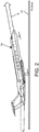
- FIG. 2 is a diagram representing a side view of an aircraft 10 taking off from a runway 12, the path of the aircraft 10 during take-off being indicated by an arrow 8.
- the data processing system is configured to expect motion data that indicates the following characteristics: (1) start from stop or taxi speed; (2) a sustained high acceleration rate until the groundspeed of the aircraft exceeds 30 knots; (3) a horizontal (only) acceleration vector (i.e., no significant vertical component) only at the beginning; and (4) an upward vertical component of the acceleration vector that starts in the middle of the acceleration vector.
- the data processing system After the data processing system has determined the Wheels Off time, it continues to scan the motion data log, searching for a deceleration vector having a downward vertical component that ends during a deceleration that corresponds to aircraft landing. More specifically, the data processing system processes the motion data to identify motion data representing a downward vertical deceleration vector of the mobile device that corresponds to aircraft landing.
- the data processing system After the data processing system has identified motion data representing the downward vertical deceleration vector of the mobile device that corresponds to aircraft landing, the data processing system also identifies time data representing an end time of that downward vertical deceleration vector. The data processing system sets a Wheels On time to be equal to that end time and then stores data representing the Wheels On time in the non-transitory tangible computer-readable storage medium. This Wheels On time corresponds to the "air/ground sensor on landing gear set to ground state" condition set forth by the Federal Aviation Administration in its definitions of OOOI times for ACARS-equipped aircraft.
- the data processing system may be further configured to calculate a groundspeed of the mobile device (which should be the same as the groundspeed of the aircraft) subsequent to the end time of the downward vertical deceleration vector and then determine that the calculated groundspeed of the mobile device is less than a specified groundspeed threshold (e.g., 30 knots). This information can be used to confirm that the detected downward vertical deceleration vector of the mobile device corresponds to aircraft landing.
- a specified groundspeed threshold e.g. 30 knots
- FIG. 3 is a diagram representing a side view of an aircraft 10 landing on a runway 12, the path of the aircraft 10 during landing being indicated by an arrow 14.
- the data processing system is configured to expect motion data that indicates the following characteristics: (1) deceleration from cruise speed; (2) the downward vertical component of the deceleration vector ends in middle of deceleration vector; and (3) the end of the downward vertical component of the deceleration vector is followed by a horizontal (only) deceleration vector to taxi speed.
- the data processing system After the data processing system has determined the Wheels On time, it continues to scan the motion data log, searching for a horizontal deceleration vector that corresponds to arriving at the gate. More specifically, the data processing system processes the motion data to identify motion data representing a horizontal deceleration vector of the mobile device that corresponds to aircraft gate arrival.
- the data processing system uses characteristics of aircraft taxi deceleration to aid accurate identification of movements of the mobile device corresponding to aircraft gate arrival.
- the data processing system processes the logged motion data to filter out motion data representing temporary stops that may occur during taxiing of the aircraft. This can be done by first searching for a time period during which the motion data indicates minimal movement of the mobile device, thereby identifying when the crew is in the cockpit after arriving at the gate.
- the data processing system is further configured to identify vertical acceleration vectors representing motion of the mobile device as the crew departs the cockpit. After the data processing system has determined when the crew departed the cockpit, the data processing system can then identify the motion data representing the most recent preceding stoppage of the aircraft, thereby eliminating any prior temporary stoppages from the analysis.
- the data processing system After the data processing system has identified motion data representing the horizontal deceleration corresponding to aircraft gate arrival, the data processing system also identifies time data representing an end time of that horizontal deceleration vector. The data processing system sets a Gate In time to be equal to that end time and then stores data representing the Gate In time in the non-transitory tangible computer-readable storage medium. This Gate In time corresponds to the "parking brake is applied" condition set forth by the Federal Aviation Administration in its definitions of OOOI times for ACARS-equipped aircraft.
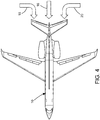
- FIG. 4 is a diagram representing a top view of an aircraft 10 having alternative possible Gate In movements (indicated by arrows).
- Arrow 16 indicates a direct movement of the aircraft 10 to a gate or a parking stop.
- Arrow 18 indicates that the aircraft 10 first taxis forward and then turns right and continues moving until the gate or parking spot is reached.
- Arrow 20 indicates that the aircraft 10 first taxis forward and then turns left moving until the gate or parking spot is reached.
- the data processing system is configured to search from the end of the motion data log for the last extended time during which the motion data indicates there was no appreciable change in the position of the mobile device. More specifically, the data processing system is configured to search for motion data representing an extended stoppage and collected after other motion data representing the horizontal acceleration vectors associated with taxiing.
- the data processing system is further configured to filter out stops/holds which occur while the aircraft is taxiing and movements which occur after the crew has departed the cockpit.
- the data processing system is also configured to expect motion data indicating a slow deceleration rate from taxi speed to a stop.
- a block time equal to the Gate In time minus the Gate Out time can be calculated and a flight time equal to the Wheels On time minus the Wheels Off time can be calculated.
- the data processing system may be configured to calculate the block time and flight time automatically or in response to a manual input by a pilot to the user interface of the mobile device.
- the data processing system is further configured to store data representing the block time and data representing the flight time in the non-transitory tangible computer-readable storage medium.
- the data processing system may be configured to control a display screen of the mobile device to display symbology representing the OOOI times, block time and flight time.
- FIG. 5 is a diagram representing a mockup of a display screen 22 for displaying OOOI data on a mobile device in accordance with one possible implementation.
- a graphics processor incorporated in the mobile device can display a multiplicity of data fields arranged in a vertical column.
- the multiplicity of data fields may comprise the following: a Gate Out time field 24, a Wheels Off time field 26, a Wheels On time field 28, a Gate In time field 30, a Day Hours field 32, a Night Hours field 34, a Total Block Time field 36, a Flight Time field 38, an Approach Type filed 40, and a Day Takeoffs field 42.
- the Gate Out, Wheels Off, Wheels On and Gate In times are determined using the OOOI time detection algorithms.
- the Day Hours and Night Hours parameters are calculated using sunset/sunrise times.
- the Total Block Time equals the Gate In time minus the Gate Out time.
- the Flight Time equals the Wheels On time minus the Wheels Off time.
- the Approach Type is received from integration with an in-flight application.
- the Day Takeoffs parameter is calculated using the Wheel Off times and sunset/sunrise times. The same principle can be used to determine the number of night landings. The pilot can modify these calculated values under appropriate circumstances.
- FIG. 6 is a block diagram identifying some components of a mobile device in accordance with one embodiment, which mobile device can be configured to detect and log OOOI data in accordance with the methods disclosed in some detail below.
- the mobile device takes the form of a wireless communications device 50, such as a cellular or mobile telephone, a personal digital assistant, a tablet computer, a laptop computer, a smart watch, a portable display device, or some other suitable type of mobile device.
- the wireless communications device 50 includes the capability for wireless communication with a ground-based flight operations center.
- the embodiment of the wireless communications device 50 depicted in FIG. 6 comprises: an antenna 62; a radio frequency transceiver 64 coupled to the antenna 62 to transmit and/or receive voice and/or digital data signals through the antenna 62; and a digital data processing system 52 (hereinafter "data processing system 52") to control the transceiver 64 and to manage the voice and digital data signals.
- the data processing system 52 may be a general-purpose processing device, such as a microprocessor or controller for example.
- Digital processing system 52 may also be a special-purpose processing device, such as an application specific integrated circuit (ASIC), a field-programmable gate array (FPGA) or a digital signal processor (DSP).
- ASIC application specific integrated circuit
- FPGA field-programmable gate array
- DSP digital signal processor
- the wireless communications device 50 further comprise a non-transitory tangible computer-readable storage medium in the form of a storage device 56, which is communicatively coupled to the data processing system 52 and which stores data and/or operating programs. Storage device 56 may, for example, be a solid-state or magnetic memory device.
- the wireless communications device 50 also comprises an input device 54, which is communicatively coupled to the data processing system 52 and which accepts user inputs.
- the input device 54 may, for example, be a keypad, a touchpad, a touch screen, a pointing device in combination with a display device or a similar input device.
- the wireless communications device 50 also comprises a display screen 22 of the type depicted in FIG. 5 .
- the display screen 22 is communicatively coupled to the data processing system 52 to display information as previously described.
- the display device 22 may, for example, be an LCD display device.
- the input device 54 and display device 22 may be integrated together in a well-known manner.
- the wireless communications device 50 also comprises a battery 60 for supplying electrical power to the other components of the system.
- the battery 60 may, for example, be a rechargeable or non-rechargeable lithium or nickel metal hydride battery.
- the wireless communications device 50 may also include an audio transducer (e.g., a speaker) and a microphone (not shown).
- the wireless communications device 50 further comprises motion sensors 66 for detecting motion of the device.
- the motion sensors 66 are a three-axis MEMS-based accelerometer, a three-axis MEMS-based gyro, and a barometer.
- the motion sensors 66 are able to detect a movement including an acceleration or de-acceleration of the wireless communications device 50.
- the motion sensors 66 may generate motion data for multiple dimensions, which may be used to determine a direction of movement of the wireless communications device 50. For example, the motion sensors 66 may generate X, Y and Z axis acceleration information when the motion sensors 66 detects that the wireless communications device 50 is moving.
- the data processing system 52 is coupled to the motion sensor 66 and configured to calculate a direction of movement of the wireless communications device 50.
- the movement vector may be determined according to one or more predetermined formulas based on the movement data (e.g., movements in X, Y and Z directions) provided by the motion sensors 66.
- the motion sensors 66 may continuously monitor the movement of the wireless communications device 50.
- the wireless communications device 50 may comprise locations sensors 68 for providing location data of the device.
- the location sensors 68 are a digital compass, GPS, GLONASS, Wi-Fi location, and beacon micro-location. According to one embodiment, the location sensors 68 provide location data for the wireless communication device 50.
- the data processing system 52 is coupled to the location sensors 68 and configured to process and record location data.
- location data may be used to improve the accuracy or efficiency of this method.
- the wireless communications device 50 further comprises a clock 58 that may be synchronized with a GPS time signal (the GPS receiver is part of the location sensors 68).
- the time data output by the clock 58 is used by the data processing system 52 to time stamp the motion data received from the motion sensor 66 when that motion data is stored in the storage device 56.
- the above-described mobile device for providing a retrievable record of OOOI times can be enhanced with additional capabilities by integration with other systems.
- the mobile device can calculate Hobbs time, fuel burns and fuel uplift, which are otherwise estimated from the flight plan.
- ACARS or aircraft Wi-Fi would allow near real-time updates of aircraft-measured OOOI times for comparison with the OOOI times from this method.
- GPS data can be used to improve the accuracy of detecting OOOI times either from aircraft integration or from third-party antennas or GPS when combined with airport and runway location data from integration with other applications.
- the GPS signals can be used to determine the location of the mobile device at the gate and on the runway, and provide enhanced location and speed information.
- In-flight application integration can provide information about the approach procedure (initially need the type), the locations of gates and runways used for the trip to aid the use of GPS data, and the flight plan to avoid manual reentry in the in-flight application.
- a mobile device for logging OOOI times may incorporate one or more computers or processors.
- data processing system means a computer system comprising one or more computers and/or one or more processors.
- each processor may be a microprocessor, a digital signal processor, a FPGA, an ASIC, or any other circuit or processing device capable of executing one or more of the functions described herein.
- the methods described herein may be encoded as executable instructions embodied in a non-transitory tangible computer-readable storage medium, including, without limitation, a persistent storage device and/or a persistent memory device. Such instructions, when executed by a computing system, cause the mobile device to perform at least a portion of the methods described herein.
Landscapes
- Engineering & Computer Science (AREA)
- Radar, Positioning & Navigation (AREA)
- Remote Sensing (AREA)
- Physics & Mathematics (AREA)
- General Physics & Mathematics (AREA)
- Business, Economics & Management (AREA)
- Economics (AREA)
- Computer Networks & Wireless Communication (AREA)
- Human Resources & Organizations (AREA)
- Entrepreneurship & Innovation (AREA)
- Development Economics (AREA)
- Marketing (AREA)
- Operations Research (AREA)
- Quality & Reliability (AREA)
- Strategic Management (AREA)
- Tourism & Hospitality (AREA)
- General Business, Economics & Management (AREA)
- Theoretical Computer Science (AREA)
- Traffic Control Systems (AREA)
- Navigation (AREA)
Abstract
Devices and methods for providing a retrievable record of the times of the actual aircraft movements such as the Gate Out time when the aircraft leaves the gate or parking position, the Wheels Off time when the aircraft takes off, the Wheels On time when the aircraft touches down during landing, and the Gate In time when the aircraft arrives at the gate or parking position (OOOI times). A mobile device for logging data onboard an aircraft comprises: a motion sensor; a clock; a non-transitory tangible computer-readable storage medium for storing motion data from the motion sensor and associated time data from the clock; and a data processing system configured to identify stored motion data representing respective acceleration/deceleration vectors of the mobile device motions that correspond to aircraft gate departure and arrival and aircraft takeoff and landing. The OOOI times are automatically logged in the non-transitory tangible computer-readable storage medium.
Description
- This disclosure relates to devices and methods for providing a retrievable record of the "Gate Out", "Wheels Off", "Wheels On" and "Gate In" times (hereinafter "OOOI data") of an aircraft.
- As used herein, the term "OOOI data" refers to times of the actual aircraft movements of Gate Out, Wheels Off, Wheels On, and Gate In. The Gate Out time indicates when the aircraft leaves the gate or parking position. The Wheels Off time indicates when the aircraft takes off. The Wheels On time indicates when the aircraft touches down. The Gate In time indicates when the aircraft arrives at the gate or parking position.
- OOOI data captured post-flight is among the most indispensable data for any flight operations organization. For example, the block time, which equals the Gate In time minus the Gate Out time, is used to measure aircraft utilization and is the basis for pilot duty times. In addition, the flight time, which equals the Wheels On time minus the Wheels Off time, is the basis for maintenance operations.
- Currently, some airlines require their flight crews to record OOOI times by hand on a per flight basis. The flight crew then verbally relays the "Gate Out" and "Wheels Off" times after departure to ground-based dispatch operations via a VHF transceiver. Upon arrival, the flight crew hand delivers the written "Wheels On" and "Gate In" times to a gate agent. It would be desirable to eliminate the need for flight crews to manually record OOOI times, thereby reducing crew workload.
- Other airlines use an Aircraft Communications Addressing and Reporting System (ACARS) Management Unit (MU) and VHF transceiver to automatically forward OOOI times to their ground-based dispatch operations. The ACARS is a digital datalink system for transmission of short messages between aircraft and ground stations via airband radio or satellite. A major function of ACARS is to automatically detect and report the start of each major flight phase, called OOOI events in the industry (out of the gate, off the ground, on the ground, and into the gate). These OOOI events are detected using input from aircraft sensors mounted on doors, parking brakes, and struts. At the start of each flight phase, an ACARS message is transmitted to the ground describing the flight phase, the time at which it occurred, and other related information such as the amount of fuel on board or the flight origin and destination. These messages are used to track the status of aircraft and crews.
- In ACARS-equipped aircraft, most OOOI times are detected and transmitted automatically by sensors (such as doors, parking brakes, and strut switch sensors). ACARS defines the Gate Out time as the moment when all passenger and cargo doors are closed and the parking brake is released. ACARS defines the Wheels Off time as the moment when the air/ground sensor on the landing gear is set to the "airborne" state, i.e., the moment when the aircraft wheels leave the runway. ACARS defines the Wheels On time as the moment when the air/ground sensor on the landing gear is set to the "ground" state, i.e., the moment when the aircraft wheels come into contact with the runway. ACARS defines the Gate In time as the moment when the parking brake is set, i.e., applied.
- Using aircraft sensor data is problematic because it can be difficult to capture and often has inaccuracies. Also aircraft in a mixed fleet will have different types of sensors, which causes automated collection to be problematic and inconsistent.
- It would be desirable to provide a device and an automated method for collecting OOOI data which is more accurate and efficient than current manual or automated methods.
- The subject matter disclosed in detail below is directed to devices and methods for providing a retrievable record of the OOOI times of aircraft movements. The method uses motion sensor data from a mobile device located onboard the aircraft. In accordance with one embodiment, the mobile device comprises motion sensors, location sensors, a clock, a non-transitory tangible computer-readable storage medium for storing motion data from the motion sensors and associated time data from the clock, and a data processing system configured to identify stored motion data representing respective acceleration/deceleration vectors of the mobile device motions that correspond to the OOOI events for a flight of the aircraft, namely, aircraft gate departure and arrival and aircraft takeoff and landing. The associated OOOI times are automatically stored in the non-transitory tangible computer-readable storage medium. (As used herein, the verbs "store" and "log" are used interchangeably and synonymously to mean "keep or make a record".)
- One aspect of the subject matter disclosed in detail below is a method for logging data onboard an aircraft, comprising: outputting motion data from a motion sensor; outputting time data from a clock representing times; storing the motion data from the motion sensor and associated time data from the clock in a non-transitory tangible computer-readable storage medium; processing the data to identify motion data representing a horizontal acceleration vector that corresponds to aircraft gate departure; identifying time data representing a begin time of the horizontal acceleration vector; setting a Gate Out time to be equal to the begin time; and storing data representing the Gate Out time in the non-transitory tangible computer-readable storage medium.
- The method described in the preceding paragraph may further comprise: processing the data to identify motion data representing a horizontal deceleration vector that corresponds to aircraft gate arrival; identifying time data representing an end time of the horizontal deceleration vector; setting a Gate In time to be equal to the end time; and storing data representing the Gate In time in the non-transitory tangible computer-readable storage medium. Optionally, if location sensor data is available, the location sensor data can be used to improve the accuracy or efficiency of this method.
- Another aspect of the subject matter disclosed in detail below is a system for logging data onboard an aircraft, comprising: a motion sensor configured to output motion data; a clock that outputs time data representing times; a non-transitory tangible computer-readable storage medium for storing motion data from the motion sensor and associated time data from the clock; and a data processing system configured to perform the following operations: identifying stored motion data representing a horizontal acceleration vector that corresponds to aircraft gate departure; identifying stored time data representing a begin time of the horizontal acceleration vector; setting a Gate Out time to be equal to the begin time; and sending data representing the Gate Out time to the non-transitory tangible computer-readable storage medium for storage. The data processing system may be further configured to perform the following operations: identifying stored motion data representing a horizontal deceleration vector that corresponds to aircraft gate arrival; identifying stored time data representing an end time of the horizontal deceleration vector; setting a Gate In time to be equal to the end time; and sending data representing the Gate In time to the non-transitory tangible computer-readable storage medium for storage. The system further comprises a display screen, wherein the data processing system is further configured to control the display screen to display symbology representing the Gate In time and the Gate Out time.
- A further aspect of the subject matter disclosed in detail below is a method for logging data onboard an aircraft, comprising: outputting motion data from a motion sensor; outputting time data from a clock representing times; storing the motion data from the motion sensor and associated time data from the clock in a non-transitory tangible computer-readable storage medium; processing the data to identify motion data representing an upward vertical acceleration vector that corresponds to aircraft takeoff; identifying time data representing a begin time of the upward vertical acceleration vector; setting a Wheels Off time to be equal to the begin time; and storing data representing the Wheels Off time in the non-transitory tangible computer-readable storage medium.
- The method described in the preceding paragraph may further comprise: processing the data to identify motion data representing a downward vertical deceleration vector that corresponds to aircraft landing; identifying time data representing an end time of the downward vertical deceleration vector; setting a Wheels On time to be equal to the end time; and storing data representing the Wheels On time in the non-transitory tangible computer-readable storage medium. Optionally, if location sensor data is available, the location sensor data can be used to improve the accuracy or efficiency of this method.
- In accordance with some embodiments of the above-described method for logging the Wheels Off time, the processing step comprises: calculating a magnitude of an upward vertical displacement subsequent to the begin time of the upward vertical acceleration vector; determining that the magnitude of the upward vertical displacement exceeds a specified vertical displacement threshold; calculating a groundspeed of the aircraft subsequent to the begin time of the upward vertical acceleration vector; and determining that the calculated groundspeed of the aircraft device exceeds a specified groundspeed threshold.
- Yet another aspect is a system for logging data onboard an aircraft, comprising: a motion sensor configured to output motion data; a clock that outputs time data representing times; a non-transitory tangible computer-readable storage medium for storing motion data from the motion sensor and associated time data from the clock; and a data processing system configured to perform the following operations: identifying stored motion data representing an upward vertical acceleration vector that corresponds to aircraft takeoff; identifying stored time data representing a begin time of the upward vertical acceleration vector; setting a Wheels Off time to be equal to the begin time; and sending data representing the Wheels Off time to the non-transitory tangible computer-readable storage medium for storage. The data processing system may be further configured to perform the following operations: identifying stored motion data representing a downward vertical deceleration vector that corresponds to aircraft landing; identifying time data representing an end time of the downward vertical deceleration vector; setting a Wheels On time to be equal to the end time; and sending data representing the Wheels On time to the non-transitory tangible computer-readable storage medium for storage. The system further comprises a display screen, wherein the data processing system is further configured to control the display screen to display symbology representing the Wheels Off time and the Wheels On time.
- Other aspects of systems and methods for logging OOOI times are disclosed below.
- The features, functions and advantages discussed in the preceding section can be achieved independently in various embodiments or may be combined in yet other embodiments. Various embodiments will be hereinafter described with reference to drawings for the purpose of illustrating the above-described and other aspects.
-
FIG. 1 is a diagram representing a top view of an aircraft having alternative possible Gate Out movements (indicated by arrows). -
FIG. 2 is a diagram representing a side view of an aircraft taking off, the path of the aircraft during take-off being indicated by an arrow. -
FIG. 3 is a diagram representing a side view of an aircraft landing, the path of the aircraft during landing being indicated by an arrow. -
FIG. 4 is a diagram representing a top view of an aircraft having alternative possible Gate In movements (indicated by arrows) to arrive at the parking position depicted. -
FIG. 5 is a diagram representing a screen mockup for displaying OOOI data on a mobile device. -
FIG. 6 is a block diagram identifying some components of a mobile device which can be configured to detect and log OOOI data in accordance with the methods disclosed in some detail below. - Reference will hereinafter be made to the drawings in which similar elements in different drawings bear the same reference numerals.
- Illustrative embodiments of a mobile device for automated logging of OOOI data are described in some detail below. However, not all features of an actual implementation are described in this specification. A person skilled in the art will appreciate that in the development of any such actual embodiment, numerous implementation-specific decisions must be made to achieve the developer's specific goals, such as compliance with system-related and business-related constraints, which will vary from one implementation to another. Moreover, it will be appreciated that such a development effort might be complex and time-consuming, but would nevertheless be a routine undertaking for those of ordinary skill in the art having the benefit of this disclosure.
- The design disclosed herein uses a mobile device's motion sensor data and not GPS data. Mobile devices typically do not have a good GPS signal inside an aircraft without the use of an external antenna. The use of an external antenna or GPS may not receive regulatory approval. In, addition the design disclosed herein does not require integration with aircraft avionics. Avionics can provide additional data such as GPS or Hobbs times. The design disclosed herein enables use in early-generation aircraft that lack interconnectivity. The design can take advantage of additional data when available.
- The methods disclosed herein use motion sensor data from a mobile device located onboard the aircraft. In accordance with one embodiment, the mobile device comprises motion sensors, location sensors, a clock, a non-transitory tangible computer-readable storage medium for storing motion data from the motion sensor and associated time data from the clock, and a data processing system configured to identify stored motion data representing respective acceleration/deceleration vectors of the mobile device motions that correspond to the OOOI events for a flight of the aircraft, namely, aircraft gate departure and arrival and aircraft takeoff and landing. More specifically, the mobile device comprises a processor that executes application logic in the form of a set of algorithms for automatically detecting and storing (i.e., logging) respective OOOI times in the non-transitory tangible computer-readable storage medium.
- In accordance with one exemplary application, the OOOI-data-logging mobile device receives flight plan information. Flight plan information may come from ground computer systems or from the flight management computer onboard the aircraft. The received flight plan information includes departure and arrival times and sunrise and/or sunset times for a flight. In addition, the OOOI-data-logging mobile device receives default taxi times from an operator to improve algorithm accuracy. Optionally, the OOOI-data-logging application can be configured to receive data from other applications hosted on the mobile device or from the aircraft avionics.
- In accordance with one embodiment, the application runs continuously on the mobile device (foreground or background). Pilots are typically in the
cockpit 30 minutes before departure. The application can either automatically or manually begin logging motion sensor data. In an exemplary automatic mode, the application may begin logging 60 minutes prior to the departure time from the flight plan. This 60-minute buffer may be configurable. In a manual mode, the pilot may manually activate the application, which starts the logging and also indicates when the pilot is in the cockpit. Data is logged until the application is used for post-flight functions. This ensures that all necessary data is logged regardless of delays or the timing of the pilot's use of the application to capture post-flight information. Multiple logs can be maintained as needed if the post-flight phase is not done before the next flight. - In accordance with some embodiments, a mobile device for logging OOOI data onboard an aircraft comprises: motion sensors configured to output motion data representing motions of the mobile device; a clock configured to output time data representing times; a non-transitory tangible computer-readable storage medium for storing motion data from the motion sensor and associated time data from the clock; and a data processing system configured to identify stored motion data representing respective acceleration/deceleration vectors for mobile device motions that correspond to the OOOI events, namely, aircraft gate departure, aircraft takeoff, aircraft landing, and aircraft gate arrival. In accordance with one implementation, the motion sensor may comprise a first accelerometer for detecting acceleration in an X direction, a second accelerometer for detecting acceleration in a Y direction and a third accelerometer for detecting acceleration in a Z direction.
- In accordance with those same embodiments, the method for logging data onboard an aircraft comprises: moving the mobile device from a location not onboard the aircraft to a location onboard the aircraft; outputting motion data from the motion sensor representing motion of the mobile device; outputting time data from the clock representing times; storing the motion data from the motion sensor and associated time data from the clock in a non-transitory tangible computer-readable storage medium; and processing the data to identify stored motion data representing respective acceleration/deceleration vectors of the mobile device motions that correspond to the OOOI events.
- The data processing system of the mobile device may be configured to execute application logic comprising a multiplicity of algorithms for detecting OOOI times (hereinafter "OOOI time detection algorithms"). For example, a single processor may be programmed to execute the multiplicity of OOOI time detection algorithms in sequence. In the alternative, more than one processor may be employed. For example, the data processing system may comprise a multiplicity of processors which process the motion sensor data concurrently, each processor being programmed to execute a respective one of the multiplicity of OOOI time detection algorithms. In accordance with one embodiment, the multiplicity of OOOI time detection algorithms include a first algorithm for detecting a Gate Out time, a second algorithm for detecting a Wheels Off time, a third algorithm for detecting a Wheels On time, and a fourth algorithm for detecting a Gate In time. The first through fourth OOOI time detection algorithms will now be described in some detail with reference to
FIGS. 1 through 4 . - In accordance with one method for detecting the gate Out time, the first OOOI time detection algorithm comprises a series of instructions executed by the data processing system of the mobile device. Starting at the beginning of the motion data log, the data processing system processes (i.e., searches) the data to identify motion data representing a horizontal acceleration vector of the mobile device that corresponds to aircraft gate departure.
- In accordance with one possible implementation, the data processing system uses characteristics of aircraft taxi acceleration or aircraft push back to aid accurate identification of movements of the mobile device corresponding to aircraft gate departure. In addition, the data processing system processes the motion data to filter out motion data representing a vertical acceleration vector of the mobile device that corresponds to movement of the mobile device when the mobile device is not in the cockpit of the aircraft, i.e., the time interval prior to the crew being in the cockpit. Further, the data processing system searches for a time period having associated motion data representing minimal motion of the mobile device to determine when the crew is in the cockpit. More specifically, the data processing system processes the data to identify motion data representing an acceleration vector of the mobile device that corresponds to minimal movement of the mobile device while the mobile device is in the cockpit of the aircraft.
- After the data processing system has identified motion data representing the horizontal acceleration corresponding to aircraft gate departure, the data processing system also identifies time data representing a begin time of that horizontal acceleration vector. The data processing system sets a Gate Out time to be equal to that begin time and then stores data representing the Gate Out time in the non-transitory tangible computer-readable storage medium. This Gate Out time corresponds to the "parking brake released" condition set forth by the Federal Aviation Administration in its definitions of OOOI times for ACARS-equipped aircraft.
-
FIG. 1 is a diagram representing a top view of anaircraft 10 having alternative possible Gate Out movements (indicated by arrows).Arrow 2 indicates a rearward movement of theaircraft 10 during push back from a gate. Arrow 4 indicates that theaircraft 10 first taxis forward and then turns right starting from a stationary position while parked on an apron. Arrow 6 indicates that theaircraft 10 first taxis forward and then turns left starting from a stationary position while parked on an apron. The data processing system is configured to expect that there will be an extended period of time during which the motion data will indicate that the aircraft had no appreciable position change just before the flight plan's departure time. The data processing system is also configured to expect motion data indicating a slow acceleration rate to taxi speeds. - After the data processing system has determined the Gate Out time, it continues to scan the motion data log, searching for an acceleration vector having an upward vertical component that corresponds to aircraft takeoff. More specifically, the data processing system processes the motion data to identify motion data representing an upward vertical acceleration vector of the mobile device that corresponds to aircraft takeoff. The data processing system is configured to expect that the motion data collected during taxiing will have minimal vertical acceleration vectors.
- After the data processing system has identified motion data representing the upward vertical acceleration vector of the mobile device that corresponds to aircraft takeoff, the data processing system also identifies time data representing a begin time of that upward vertical acceleration vector. The data processing system sets a Wheels Off time to be equal to that begin time and then stores data representing the Wheels Off time in the non-transitory tangible computer-readable storage medium. This Wheels Off time corresponds to the "air/ground sensor on landing gear set to airborne state" condition set forth by the Federal Aviation Administration in its definitions of OOOI times for ACARS-equipped aircraft.
- Optionally, the data processing system may be further configured to calculate a magnitude of an upward vertical displacement of the mobile device subsequent to the begin time of the upward vertical acceleration vector and then determine that the calculated magnitude of the upward vertical displacement of the mobile device exceeds a specified vertical displacement threshold (e.g., 5 feet). In addition, the data processing system may be further configured to calculate a groundspeed of the mobile device (which should be the same as the groundspeed of the aircraft) subsequent to the begin time of the upward vertical acceleration vector and then determine that the calculated groundspeed of the mobile device exceeds a specified groundspeed threshold (e.g., 30 knots). This information can be used to confirm that the detected upward vertical acceleration vector of the mobile device corresponds to aircraft takeoff.
-
FIG. 2 is a diagram representing a side view of anaircraft 10 taking off from arunway 12, the path of theaircraft 10 during take-off being indicated by anarrow 8. For the purpose of determining the Wheels Off time, the data processing system is configured to expect motion data that indicates the following characteristics: (1) start from stop or taxi speed; (2) a sustained high acceleration rate until the groundspeed of the aircraft exceeds 30 knots; (3) a horizontal (only) acceleration vector (i.e., no significant vertical component) only at the beginning; and (4) an upward vertical component of the acceleration vector that starts in the middle of the acceleration vector. - After the data processing system has determined the Wheels Off time, it continues to scan the motion data log, searching for a deceleration vector having a downward vertical component that ends during a deceleration that corresponds to aircraft landing. More specifically, the data processing system processes the motion data to identify motion data representing a downward vertical deceleration vector of the mobile device that corresponds to aircraft landing.
- After the data processing system has identified motion data representing the downward vertical deceleration vector of the mobile device that corresponds to aircraft landing, the data processing system also identifies time data representing an end time of that downward vertical deceleration vector. The data processing system sets a Wheels On time to be equal to that end time and then stores data representing the Wheels On time in the non-transitory tangible computer-readable storage medium. This Wheels On time corresponds to the "air/ground sensor on landing gear set to ground state" condition set forth by the Federal Aviation Administration in its definitions of OOOI times for ACARS-equipped aircraft.
- Optionally, the data processing system may be further configured to calculate a groundspeed of the mobile device (which should be the same as the groundspeed of the aircraft) subsequent to the end time of the downward vertical deceleration vector and then determine that the calculated groundspeed of the mobile device is less than a specified groundspeed threshold (e.g., 30 knots). This information can be used to confirm that the detected downward vertical deceleration vector of the mobile device corresponds to aircraft landing.
-
FIG. 3 is a diagram representing a side view of anaircraft 10 landing on arunway 12, the path of theaircraft 10 during landing being indicated by anarrow 14. For the purpose of determining the Wheels On time, the data processing system is configured to expect motion data that indicates the following characteristics: (1) deceleration from cruise speed; (2) the downward vertical component of the deceleration vector ends in middle of deceleration vector; and (3) the end of the downward vertical component of the deceleration vector is followed by a horizontal (only) deceleration vector to taxi speed. - After the data processing system has determined the Wheels On time, it continues to scan the motion data log, searching for a horizontal deceleration vector that corresponds to arriving at the gate. More specifically, the data processing system processes the motion data to identify motion data representing a horizontal deceleration vector of the mobile device that corresponds to aircraft gate arrival.
- In accordance with one possible implementation, the data processing system uses characteristics of aircraft taxi deceleration to aid accurate identification of movements of the mobile device corresponding to aircraft gate arrival. In addition, the data processing system processes the logged motion data to filter out motion data representing temporary stops that may occur during taxiing of the aircraft. This can be done by first searching for a time period during which the motion data indicates minimal movement of the mobile device, thereby identifying when the crew is in the cockpit after arriving at the gate. The data processing system is further configured to identify vertical acceleration vectors representing motion of the mobile device as the crew departs the cockpit. After the data processing system has determined when the crew departed the cockpit, the data processing system can then identify the motion data representing the most recent preceding stoppage of the aircraft, thereby eliminating any prior temporary stoppages from the analysis.
- After the data processing system has identified motion data representing the horizontal deceleration corresponding to aircraft gate arrival, the data processing system also identifies time data representing an end time of that horizontal deceleration vector. The data processing system sets a Gate In time to be equal to that end time and then stores data representing the Gate In time in the non-transitory tangible computer-readable storage medium. This Gate In time corresponds to the "parking brake is applied" condition set forth by the Federal Aviation Administration in its definitions of OOOI times for ACARS-equipped aircraft.
-
FIG. 4 is a diagram representing a top view of anaircraft 10 having alternative possible Gate In movements (indicated by arrows).Arrow 16 indicates a direct movement of theaircraft 10 to a gate or a parking stop.Arrow 18 indicates that theaircraft 10 first taxis forward and then turns right and continues moving until the gate or parking spot is reached.Arrow 20 indicates that theaircraft 10 first taxis forward and then turns left moving until the gate or parking spot is reached. The data processing system is configured to search from the end of the motion data log for the last extended time during which the motion data indicates there was no appreciable change in the position of the mobile device. More specifically, the data processing system is configured to search for motion data representing an extended stoppage and collected after other motion data representing the horizontal acceleration vectors associated with taxiing. The data processing system is further configured to filter out stops/holds which occur while the aircraft is taxiing and movements which occur after the crew has departed the cockpit. The data processing system is also configured to expect motion data indicating a slow deceleration rate from taxi speed to a stop. - Following storage of all of the OOOI times in the non-transitory tangible computer-readable storage medium, a block time equal to the Gate In time minus the Gate Out time can be calculated and a flight time equal to the Wheels On time minus the Wheels Off time can be calculated. The data processing system may be configured to calculate the block time and flight time automatically or in response to a manual input by a pilot to the user interface of the mobile device. The data processing system is further configured to store data representing the block time and data representing the flight time in the non-transitory tangible computer-readable storage medium. In addition, the data processing system may be configured to control a display screen of the mobile device to display symbology representing the OOOI times, block time and flight time.
-
FIG. 5 is a diagram representing a mockup of adisplay screen 22 for displaying OOOI data on a mobile device in accordance with one possible implementation. In response to an input by pilot, a graphics processor incorporated in the mobile device can display a multiplicity of data fields arranged in a vertical column. The multiplicity of data fields may comprise the following: a GateOut time field 24, a Wheels Offtime field 26, a Wheels Ontime field 28, a Gate Intime field 30, aDay Hours field 32, aNight Hours field 34, a TotalBlock Time field 36, aFlight Time field 38, an Approach Type filed 40, and aDay Takeoffs field 42. As previously described, the Gate Out, Wheels Off, Wheels On and Gate In times are determined using the OOOI time detection algorithms. The Day Hours and Night Hours parameters are calculated using sunset/sunrise times. The Total Block Time equals the Gate In time minus the Gate Out time. The Flight Time equals the Wheels On time minus the Wheels Off time. The Approach Type is received from integration with an in-flight application. The Day Takeoffs parameter is calculated using the Wheel Off times and sunset/sunrise times. The same principle can be used to determine the number of night landings. The pilot can modify these calculated values under appropriate circumstances. -
FIG. 6 is a block diagram identifying some components of a mobile device in accordance with one embodiment, which mobile device can be configured to detect and log OOOI data in accordance with the methods disclosed in some detail below. In this example, the mobile device takes the form of awireless communications device 50, such as a cellular or mobile telephone, a personal digital assistant, a tablet computer, a laptop computer, a smart watch, a portable display device, or some other suitable type of mobile device. Thewireless communications device 50 includes the capability for wireless communication with a ground-based flight operations center. - More specifically, the embodiment of the
wireless communications device 50 depicted inFIG. 6 comprises: anantenna 62; aradio frequency transceiver 64 coupled to theantenna 62 to transmit and/or receive voice and/or digital data signals through theantenna 62; and a digital data processing system 52 (hereinafter "data processing system 52") to control thetransceiver 64 and to manage the voice and digital data signals. Thedata processing system 52 may be a general-purpose processing device, such as a microprocessor or controller for example.Digital processing system 52 may also be a special-purpose processing device, such as an application specific integrated circuit (ASIC), a field-programmable gate array (FPGA) or a digital signal processor (DSP). Thewireless communications device 50 further comprise a non-transitory tangible computer-readable storage medium in the form of astorage device 56, which is communicatively coupled to thedata processing system 52 and which stores data and/or operating programs.Storage device 56 may, for example, be a solid-state or magnetic memory device. Thewireless communications device 50 also comprises aninput device 54, which is communicatively coupled to thedata processing system 52 and which accepts user inputs. Theinput device 54 may, for example, be a keypad, a touchpad, a touch screen, a pointing device in combination with a display device or a similar input device. Thewireless communications device 50 also comprises adisplay screen 22 of the type depicted inFIG. 5 . Thedisplay screen 22 is communicatively coupled to thedata processing system 52 to display information as previously described. Thedisplay device 22 may, for example, be an LCD display device. Theinput device 54 anddisplay device 22 may be integrated together in a well-known manner. Thewireless communications device 50 also comprises abattery 60 for supplying electrical power to the other components of the system. Thebattery 60 may, for example, be a rechargeable or non-rechargeable lithium or nickel metal hydride battery. Thewireless communications device 50 may also include an audio transducer (e.g., a speaker) and a microphone (not shown). - The
wireless communications device 50 further comprisesmotion sensors 66 for detecting motion of the device. In accordance with one implementation, themotion sensors 66 are a three-axis MEMS-based accelerometer, a three-axis MEMS-based gyro, and a barometer. According to one embodiment, themotion sensors 66 are able to detect a movement including an acceleration or de-acceleration of thewireless communications device 50. Themotion sensors 66 may generate motion data for multiple dimensions, which may be used to determine a direction of movement of thewireless communications device 50. For example, themotion sensors 66 may generate X, Y and Z axis acceleration information when themotion sensors 66 detects that thewireless communications device 50 is moving. - In addition, the
data processing system 52 is coupled to themotion sensor 66 and configured to calculate a direction of movement of thewireless communications device 50. The movement vector may be determined according to one or more predetermined formulas based on the movement data (e.g., movements in X, Y and Z directions) provided by themotion sensors 66. Themotion sensors 66 may continuously monitor the movement of thewireless communications device 50. - Further, the
wireless communications device 50 may compriselocations sensors 68 for providing location data of the device. In accordance with one implementation, thelocation sensors 68 are a digital compass, GPS, GLONASS, Wi-Fi location, and beacon micro-location. According to one embodiment, thelocation sensors 68 provide location data for thewireless communication device 50. - In addition, the
data processing system 52 is coupled to thelocation sensors 68 and configured to process and record location data. When available, location data may be used to improve the accuracy or efficiency of this method. - Lastly, the
wireless communications device 50 further comprises aclock 58 that may be synchronized with a GPS time signal (the GPS receiver is part of the location sensors 68). The time data output by theclock 58 is used by thedata processing system 52 to time stamp the motion data received from themotion sensor 66 when that motion data is stored in thestorage device 56. - The above-described mobile device for providing a retrievable record of OOOI times can be enhanced with additional capabilities by integration with other systems. When integrated with aircraft avionics, the mobile device can calculate Hobbs time, fuel burns and fuel uplift, which are otherwise estimated from the flight plan. Also ACARS or aircraft Wi-Fi would allow near real-time updates of aircraft-measured OOOI times for comparison with the OOOI times from this method. GPS data can be used to improve the accuracy of detecting OOOI times either from aircraft integration or from third-party antennas or GPS when combined with airport and runway location data from integration with other applications. The GPS signals can be used to determine the location of the mobile device at the gate and on the runway, and provide enhanced location and speed information. In-flight application integration can provide information about the approach procedure (initially need the type), the locations of gates and runways used for the trip to aid the use of GPS data, and the flight plan to avoid manual reentry in the in-flight application.
- While devices and methods for providing a retrievable record of the OOOI times for actual aircraft movements have been described with reference to various embodiments, it will be understood by those skilled in the art that various changes may be made and equivalents may be substituted for elements thereof without departing from the scope of the claims set forth hereinafter. In addition, many modifications may be made to adapt the teachings herein to a particular situation without departing from the scope of the claims.
- The embodiments of a mobile device for logging OOOI times disclosed above may incorporate one or more computers or processors. As used in the claims, the term "data processing system" means a computer system comprising one or more computers and/or one or more processors. As previously described, each processor may be a microprocessor, a digital signal processor, a FPGA, an ASIC, or any other circuit or processing device capable of executing one or more of the functions described herein.
- The methods described herein may be encoded as executable instructions embodied in a non-transitory tangible computer-readable storage medium, including, without limitation, a persistent storage device and/or a persistent memory device. Such instructions, when executed by a computing system, cause the mobile device to perform at least a portion of the methods described herein.
- Further, the disclosure comprises embodiments according to the following clauses
-
Clause 1. A method for logging data onboard an aircraft, comprising:- outputting motion data from a motion sensor;
- outputting time data from a clock representing times;
- storing the motion data from the motion sensor and associated time data
- from the clock in a non-transitory tangible computer-readable storage medium;
- processing the data to identify motion data representing a horizontal acceleration vector that corresponds to aircraft gate departure;
- identifying time data representing a begin time of the horizontal acceleration vector;
- setting a Gate Out time to be equal to the begin time; and
- storing data representing the Gate Out time in the non-transitory tangible computer-readable storage medium.
-
Clause 2. The method as recited inClause 1, wherein the motion sensor and clock are incorporated in a mobile device, further comprising processing the data to filter out motion data representing a vertical acceleration vector of the mobile device that corresponds to movement of the mobile device when the mobile device is not in a cockpit of the aircraft. - Clause 3. The method as recited in
Clause 2, further comprising processing the data to identify motion data representing an acceleration vector of the mobile device that corresponds to minimal movement of the mobile device while the mobile device is in the cockpit of the aircraft. - Clause 4. The method as recited in any of Clauses 1-3, further comprising:
- processing the data to identify motion data representing a horizontal deceleration vector that corresponds to aircraft gate arrival;
- identifying time data representing an end time of the horizontal deceleration vector;
- setting a Gate In time to be equal to the end time; and
- storing data representing the Gate In time in the non-transitory tangible computer-readable storage medium.
- Clause 5. The method as recited in Clause 4, further comprising:
- calculating a block time equal to the Gate In time minus the Gate Out time; and
- storing data representing the block time in the non-transitory tangible computer-readable storage medium.
- Clause 6. The method as recited in any of Clauses 4-5, further comprising displaying symbology representing the Gate In time and the Gate Out time.
- Clause 7. The method as recited in any of Clauses 4-6, further comprising processing the data to filter out motion data representing a horizontal deceleration vector that corresponds to a temporary stop of the aircraft during taxiing.
- 8. A system for logging data onboard an aircraft, comprising:
- a motion sensor configured to output motion data;
- a clock that outputs time data representing times;
- a non-transitory tangible computer-readable storage medium for storing motion data from the motion sensor and associated time data from the clock; and
- a data processing system configured to perform the following operations:
identifying stored motion data representing a horizontal acceleration vector that corresponds to aircraft gate departure; - identifying stored time data representing a begin time of the horizontal acceleration vector;
- setting a Gate Out time to be equal to the begin time; and
- sending data representing the Gate Out time to the non-transitory tangible computer-readable storage medium for storage.
- Clause 9. The system as recited in
Clause 8, wherein the data processing system is further configured to perform the following operations:- identifying stored motion data representing a horizontal deceleration vector that corresponds to aircraft gate arrival;
- identifying stored time data representing an end time of the horizontal deceleration vector;
- setting a Gate In time to be equal to the end time; and
- sending data representing the Gate In time to the non-transitory tangible computer-readable storage medium for storage.
-
Clause 10. The system as recited in Clause 9, further comprising a display screen, wherein the data processing system is further configured to control the display screen to display symbology representing the Gate In time and the Gate Out time. - Clause 11. A method for logging data onboard an aircraft, comprising:
- outputting motion data from a motion sensor;
- outputting time data from a clock representing times;
- storing the motion data from the motion sensor and associated time data from the clock in a non-transitory tangible computer-readable storage medium;
- processing the data to identify motion data representing an upward vertical acceleration vector that corresponds to aircraft takeoff;
- identifying time data representing a begin time of the upward vertical acceleration vector;
- setting a Wheels Off time to be equal to the begin time; and
- storing data representing the Wheels Off time in the non-transitory tangible computer-readable storage medium.
-
Clause 12. The method as recited in Clause 11, wherein the processing step comprises:- calculating a magnitude of an upward vertical displacement subsequent to the begin time of the upward vertical acceleration vector; and
- determining that the magnitude of the upward vertical displacement exceeds a specified vertical displacement threshold.
- Clause 13. The method as recited in
Clause 12, wherein the processing step comprises:- calculating a groundspeed of the aircraft subsequent to the begin time of the upward vertical acceleration vector; and
- determining that the calculated groundspeed of the aircraft exceeds a specified groundspeed threshold.
-
Clause 14. The method as recited in any of Clauses 11-13, further comprising:
processing the data to identify motion data representing a downward vertical deceleration vector that corresponds to aircraft landing;
identifying time data representing an end time of the downward vertical deceleration vector;
setting a Wheels On time to be equal to the end time; and
storing data representing the Wheels On time in the non-transitory tangible computer-readable storage medium. - Clause 15. The method as recited in
Clause 14, further comprising:- calculating a flight time equal to the Wheels On time minus the Wheels Off time; and
- storing data representing the flight time in the non-transitory tangible computer-readable storage medium.
-
Clause 16. The method as recited in any of Clauses 14-15, further comprising displaying symbology representing the Wheels On time and the Wheels Off time. - Clause 17. The method as recited in any of Clauses 14-16, wherein the processing step comprises:
- calculating a groundspeed of the aircraft subsequent to the end time of the downward vertical deceleration vector; and
- determining that the calculated groundspeed of the aircraft is less than a specified groundspeed threshold.
-
Clause 18. A system for logging data onboard an aircraft, comprising:- a motion sensor configured to output motion data;
- a clock that outputs time data representing times;
- a non-transitory tangible computer-readable storage medium for storing motion data from the motion sensor and associated time data from the clock; and
- a data processing system configured to perform the following operations:
- identifying stored motion data representing an upward vertical acceleration vector that corresponds to aircraft takeoff;
- identifying stored time data representing a begin time of the upward vertical acceleration vector;
- setting a Wheels Off time to be equal to the begin time; and
- sending data representing the Wheels Off time to the non-transitory tangible computer-readable storage medium for storage.
- Clause 19. The system as recited in
Clause 18, wherein the data processing system is further configured to perform the following operations:- identifying stored motion data representing a downward vertical deceleration vector that corresponds to aircraft landing;
- identifying time data representing an end time of the downward vertical deceleration vector;
- setting a Wheels On time to be equal to the end time; and
- sending data representing the Wheels On time to the non-transitory tangible computer-readable storage medium for storage.
-
Clause 20. The system as recited in Clause 19, further comprising a display screen, wherein the data processing system is further configured to control the display screen to display symbology representing the Wheels Off time and the Wheels On time. - The method claims set forth hereinafter should not be construed to require that the steps recited therein be performed in alphabetical order (any alphabetical ordering in the claims is used solely for the purpose of referencing previously recited steps) or in the order in which they are recited unless the claim language explicitly specifies or states conditions indicating a particular order in which some or all of those steps are performed. Nor should the method claims be construed to exclude any portions of two or more steps being performed concurrently or alternatingly unless the claim language explicitly states a condition that precludes such an interpretation.
Claims (15)
- A method for logging data onboard an aircraft, comprising:outputting motion data from a motion sensor 66;outputting time data from a clock 58 representing times;storing the motion data from the motion sensor 66 and associated time data from the clock 58 in a non-transitory tangible computer-readable storage medium 56;processing the data to identify motion data representing a horizontal acceleration vector that corresponds to aircraft gate departure;identifying time data representing a begin time of the horizontal acceleration vector;setting a Gate Out time to be equal to the begin time; andstoring data representing the Gate Out time in the non-transitory tangible computer-readable storage medium 56.
- The method as recited in claim 1, wherein the motion sensor 66 and clock 58 are incorporated in a mobile device, further comprising processing the data to filter out motion data representing a vertical acceleration vector of the mobile device that corresponds to movement of the mobile device when the mobile device is not in a cockpit of the aircraft.
- The method as recited in claim 2, further comprising processing the data to identify motion data representing an acceleration vector of the mobile device that corresponds to minimal movement of the mobile device while the mobile device is in the cockpit of the aircraft.
- The method as recited in any of claims 1-3, further comprising:processing the data to identify motion data representing a horizontal deceleration vector that corresponds to aircraft gate arrival;identifying time data representing an end time of the horizontal deceleration vector;setting a Gate In time to be equal to the end time; andstoring data representing the Gate In time in the non-transitory tangible computer-readable storage medium.
- The method as recited in claim 4, further comprising:calculating a block time equal to the Gate In time minus the Gate Out time; andstoring data representing the block time in the non-transitory tangible computer-readable storage medium 56.
- The method as recited in any of claims 4-5, further comprising displaying symbology representing the Gate In time and the Gate Out time.
- The method as recited in any of claims 4-6, further comprising processing the data to filter out motion data representing a horizontal deceleration vector that corresponds to a temporary stop of the aircraft during taxiing.
- A system for logging data onboard an aircraft, comprising:a motion sensor 66 configured to output motion data;a clock 58 that outputs time data representing times;a non-transitory tangible computer-readable storage medium 56 for storing motion data from the motion sensor and associated time data from the clock 58; anda data processing system 52 configured to perform the following operations:identifying stored motion data representing a horizontal acceleration vector that corresponds to aircraft gate departure;identifying stored time data representing a begin time of the horizontal acceleration vector;setting a Gate Out time to be equal to the begin time; andsending data representing the Gate Out time to the non-transitory tangible computer-readable storage medium 56 for storage.
- A method for logging data onboard an aircraft, comprising:outputting motion data from a motion sensor 66;outputting time data from a clock 58 representing times;storing the motion data from the motion sensor 66 and associated time data from the clock 58 in a non-transitory tangible computer-readable storage medium 56;processing the data to identify motion data representing an upward vertical acceleration vector that corresponds to aircraft 10 takeoff;identifying time data representing a begin time of the upward vertical acceleration vector;setting a Wheels Off time to be equal to the begin time; andstoring data representing the Wheels Off time in the non-transitory tangible computer-readable storage medium 56.
- The method as recited in claim 9, wherein the processing step comprises:calculating a magnitude of an upward vertical displacement subsequent to the begin time of the upward vertical acceleration vector; anddetermining that the magnitude of the upward vertical displacement exceeds a specified vertical displacement threshold.
- The method as recited in claim 10, wherein the processing step comprises:calculating a groundspeed of the aircraft 10 subsequent to the begin time of the upward vertical acceleration vector; anddetermining that the calculated groundspeed of the aircraft 10 exceeds a specified groundspeed threshold.
- The method as recited in any of claims 9-11, further comprising:processing the data to identify motion data representing a downward vertical deceleration vector that corresponds to aircraft landing;identifying time data representing an end time of the downward vertical deceleration vector;setting a Wheels On time to be equal to the end time; andstoring data representing the Wheels On time in the non-transitory tangible computer-readable storage medium.
- A system for logging data onboard an aircraft, comprising:a motion sensor 66 configured to output motion data;a clock 58 that outputs time data representing times;a non-transitory tangible computer-readable storage medium 56 for storing motion data from the motion sensor 66 and associated time data from the clock 58; anda data processing system 52 configured to perform the following operations:identifying stored motion data representing an upward vertical acceleration vector that corresponds to aircraft takeoff;identifying stored time data representing a begin time of the upward vertical acceleration vector;setting a Wheels Off time to be equal to the begin time; andsending data representing the Wheels Off time to the non-transitory tangible computer-readable storage medium for storage.
- The system as recited in claim 13, wherein the data processing system is further configured to perform the following operations:identifying stored motion data representing a downward vertical deceleration vector that corresponds to aircraft landing;identifying time data representing an end time of the downward vertical deceleration vector;setting a Wheels On time to be equal to the end time; andsending data representing the Wheels On time to the non-transitory tangible computer-readable storage medium for storage.
- The system as recited in claim 14, further comprising a display screen 22, wherein the data processing system 52 is further configured to control the display screen 22 to display symbology representing the Wheels Off time and the Wheels On time.
Applications Claiming Priority (1)
| Application Number | Priority Date | Filing Date | Title |
|---|---|---|---|
| US15/598,874 US10796508B2 (en) | 2017-05-18 | 2017-05-18 | Automated logging of aircraft OOOI times using mobile device |
Publications (1)
| Publication Number | Publication Date |
|---|---|
| EP3404595A1 true EP3404595A1 (en) | 2018-11-21 |
Family
ID=61911347
Family Applications (1)
| Application Number | Title | Priority Date | Filing Date |
|---|---|---|---|
| EP18163047.6A Withdrawn EP3404595A1 (en) | 2017-05-18 | 2018-03-21 | Automated logging of aircraft oooi times using mobile device |
Country Status (4)
| Country | Link |
|---|---|
| US (2) | US10796508B2 (en) |
| EP (1) | EP3404595A1 (en) |
| CN (1) | CN108961463B (en) |
| CA (1) | CA2999151C (en) |
Families Citing this family (12)
| Publication number | Priority date | Publication date | Assignee | Title |
|---|---|---|---|---|
| US10867508B2 (en) | 2015-12-17 | 2020-12-15 | Tive, Inc. | Multi-sensor electronic device with wireless connectivity and sensing as a service platform and web application |
| US10796508B2 (en) * | 2017-05-18 | 2020-10-06 | The Boeing Company | Automated logging of aircraft OOOI times using mobile device |
| US10387808B1 (en) * | 2017-09-08 | 2019-08-20 | Aviation Aero Tix, Llc | System and method for the collection, display, and reporting of uplift data |
| US10565882B1 (en) * | 2017-09-13 | 2020-02-18 | Rockwell Collins, Inc. | Vertical situation display past and projected path depiction |
| US10629067B1 (en) * | 2018-06-29 | 2020-04-21 | Tive, Inc. | Selective prevention of signal transmission by device during aircraft takeoff and/or landing |
| US11192664B2 (en) * | 2018-12-10 | 2021-12-07 | Hamilton Sundstrand Corporation | Smart application for aircraft performance data collection |
| CN113176750B (en) * | 2021-04-23 | 2022-08-12 | 飞友科技有限公司 | Method for identifying take-off and landing of aircraft, terminal device and computer-readable storage medium |
| CN115331329A (en) * | 2021-05-11 | 2022-11-11 | 波音公司 | Master aircraft with mobile device-based system for collecting and disseminating flight data |
| US12002368B2 (en) | 2021-05-11 | 2024-06-04 | The Boeing Company | Host aircraft with mobile device-based system for collecting and disseminating flight data |
| CN113110072B (en) * | 2021-06-15 | 2021-09-03 | 深圳联和智慧科技有限公司 | Unmanned aerial vehicle residual power real-time monitoring method and system based on smart lamp post |
| US11955015B2 (en) | 2021-07-14 | 2024-04-09 | The Boeing Company | Flight data aggregation system including portable electronic devices |
| EP4467467A1 (en) * | 2023-05-25 | 2024-11-27 | B/E Aerospace, Inc. | Method and apparatus for identifying an aircraft |
Citations (2)
| Publication number | Priority date | Publication date | Assignee | Title |
|---|---|---|---|---|
| EP2284563A1 (en) * | 2009-08-13 | 2011-02-16 | Deutsche Telekom AG | Method for detecting air plane flight events, mobile communication device, and computational unit therefor |
| US20130060514A1 (en) * | 2011-09-01 | 2013-03-07 | Qualcomm Incorporated | Mems accelerometer airliner takeoff and landing detection |
Family Cites Families (15)
| Publication number | Priority date | Publication date | Assignee | Title |
|---|---|---|---|---|
| US5815407A (en) * | 1995-12-14 | 1998-09-29 | Motorola Inc. | Method and device for inhibiting the operation of an electronic device during take-off and landing of an aircraft |
| US6154636A (en) | 1999-05-14 | 2000-11-28 | Harris Corporation | System and method of providing OOOI times of an aircraft |
| US7908042B2 (en) | 2001-02-13 | 2011-03-15 | The Boeing Company | Methods and apparatus for wireless upload and download of aircraft data |
| DE10161879B4 (en) * | 2001-12-17 | 2004-09-09 | Volker Peters | Method and device for determining the take-off and landing times of an aircraft |
| US20070142980A1 (en) * | 2005-12-19 | 2007-06-21 | Marc Ausman | Avionics method and apparatus |
| US20080159158A1 (en) * | 2006-12-29 | 2008-07-03 | Clarence Edward Poisson | Method for testing a maintenance and materials management system |
| WO2011017812A1 (en) * | 2009-08-11 | 2011-02-17 | Aeromechanical Services Ltd. | Automated aircraft flight data delivery and management system with demand mode |
| EP2503416A1 (en) * | 2011-03-23 | 2012-09-26 | Hamilton International AG | Zählinstrument der Dauer von verschiedenen Phasen |
| US8825234B2 (en) | 2012-10-15 | 2014-09-02 | The Boeing Company | Turbulence mitigation for touch screen systems |
| US9911101B2 (en) * | 2014-09-29 | 2018-03-06 | The Boeing Company | Duty block time control via statistical analysis |
| GB2536497A (en) * | 2015-03-20 | 2016-09-21 | Airbus Operations Ltd | Method of monitoring the pressure of an aircraft tyre |
| US9613537B2 (en) | 2015-07-29 | 2017-04-04 | The Boeing Company | Multiple landing threshold aircraft arrival system |
| CN106650764B (en) * | 2016-08-16 | 2019-08-02 | 南京航空航天大学 | Classification and identification method of aircraft taxiing situation factors for airport arrival and departure |
| US10235892B1 (en) * | 2017-05-05 | 2019-03-19 | Architecture Technology Corporation | Aircraft surface state event track system and method |
| US10796508B2 (en) * | 2017-05-18 | 2020-10-06 | The Boeing Company | Automated logging of aircraft OOOI times using mobile device |
-
2017
- 2017-05-18 US US15/598,874 patent/US10796508B2/en active Active
-
2018
- 2018-03-21 EP EP18163047.6A patent/EP3404595A1/en not_active Withdrawn
- 2018-03-22 CA CA2999151A patent/CA2999151C/en active Active
- 2018-04-17 CN CN201810341439.9A patent/CN108961463B/en active Active
-
2020
- 2020-09-04 US US17/012,428 patent/US11521441B2/en active Active
Patent Citations (2)
| Publication number | Priority date | Publication date | Assignee | Title |
|---|---|---|---|---|
| EP2284563A1 (en) * | 2009-08-13 | 2011-02-16 | Deutsche Telekom AG | Method for detecting air plane flight events, mobile communication device, and computational unit therefor |
| US20130060514A1 (en) * | 2011-09-01 | 2013-03-07 | Qualcomm Incorporated | Mems accelerometer airliner takeoff and landing detection |
Non-Patent Citations (1)
| Title |
|---|
| GÜRKAN: "Wireless 3-axis accelerometer system for measurement of structural displacement - IEEE Conference Publication", 30 November 2013 (2013-11-30), XP055602280, Retrieved from the Internet <URL:https://ieeexplore.ieee.org/ielx7/6709575/6713796/06713871.pdf?tp=&arnumber=6713871&isnumber=6713796&ref=aHR0cHM6Ly9pZWVleHBsb3JlLmllZWUub3JnL2RvY3VtZW50LzY3MTM4NzE=> [retrieved on 20190704] * |
Also Published As
| Publication number | Publication date |
|---|---|
| US11521441B2 (en) | 2022-12-06 |
| CN108961463B (en) | 2022-03-04 |
| US20180336743A1 (en) | 2018-11-22 |
| CN108961463A (en) | 2018-12-07 |
| CA2999151C (en) | 2022-11-08 |
| CA2999151A1 (en) | 2018-11-18 |
| US10796508B2 (en) | 2020-10-06 |
| US20200402326A1 (en) | 2020-12-24 |
Similar Documents
| Publication | Publication Date | Title |
|---|---|---|
| US11521441B2 (en) | Automated logging of aircraft OOOI times using mobile device | |
| CN107272028B (en) | Navigation equipment on-line monitoring and flight check system and method based on unmanned plane | |
| US11727818B1 (en) | Aircraft surface state event track system and method | |
| EP3194273B1 (en) | Fail safe aircraft monitoring and tracking | |
| EP3159869B1 (en) | Aircraft maneuver data management system | |
| US11869373B1 (en) | Autonomous and automatic, predictive aircraft surface state event track system and corresponding methods | |
| EP2597633A2 (en) | System and methods for situation awareness, advisory, tracking, and aircraft control information | |
| JP2019040596A (en) | Aircraft arrival determination system and aircraft arrival determination method | |
| EP4089653A1 (en) | Host aircraft with mobile device-based system for collecting and disseminating flight data | |
| US20220139232A1 (en) | Systems and methods for predicting flight data | |
| EP3816649A1 (en) | Systems and methods for supplemental navigation using distributed avionics processing | |
| US20200242950A1 (en) | Methods and systems for vehicle position reporting and managing historical position information | |
| CN116002060A (en) | General aircraft domestic integrated avionics system architecture | |
| KR101410135B1 (en) | Apparatus for analyzing error of flight control using air traffic control data | |
| EP3112813A1 (en) | Systems and methods for location aware augmented vision aircraft monitoring and inspection | |
| CN108983314A (en) | A kind of Weather modification operation safety management application system and its working method | |
| CN107765703A (en) | A kind of Airborne Formation Flying instruction system based on inertia/satellite Relative Navigation | |
| CN109634303B (en) | Aviation automatic silencing method for portable electronic equipment | |
| Wilson et al. | Flight test and evaluation of a prototype sense and avoid system onboard a scaneagle unmanned aircraft | |
| CN116263888B (en) | Methods and related equipment for predicting flight arrival and/or departure times. | |
| CN110620987A (en) | Airport barrier vehicle early warning system based on high-precision positioning and ADS-B system | |
| CN111833658A (en) | Identification method and identification system of aircraft landing and docking process | |
| US12525132B2 (en) | Detection and reporting of aircraft diversion events | |
| US20250022380A1 (en) | In-flight maneuver detection | |
| CN110706551A (en) | Multi-mode unmanned aerial vehicle operator training simulator |
Legal Events
| Date | Code | Title | Description |
|---|---|---|---|
| STAA | Information on the status of an ep patent application or granted ep patent |
Free format text: STATUS: EXAMINATION IS IN PROGRESS |
|
| PUAI | Public reference made under article 153(3) epc to a published international application that has entered the european phase |
Free format text: ORIGINAL CODE: 0009012 |
|
| 17P | Request for examination filed |
Effective date: 20180321 |
|
| AK | Designated contracting states |
Kind code of ref document: A1 Designated state(s): AL AT BE BG CH CY CZ DE DK EE ES FI FR GB GR HR HU IE IS IT LI LT LU LV MC MK MT NL NO PL PT RO RS SE SI SK SM TR |
|
| AX | Request for extension of the european patent |
Extension state: BA ME |
|
| STAA | Information on the status of an ep patent application or granted ep patent |
Free format text: STATUS: THE APPLICATION HAS BEEN WITHDRAWN |
|
| 18W | Application withdrawn |
Effective date: 20191210 |