EP3404504A2 - Method and device for drawing room layout - Google Patents
Method and device for drawing room layout Download PDFInfo
- Publication number
- EP3404504A2 EP3404504A2 EP18168575.1A EP18168575A EP3404504A2 EP 3404504 A2 EP3404504 A2 EP 3404504A2 EP 18168575 A EP18168575 A EP 18168575A EP 3404504 A2 EP3404504 A2 EP 3404504A2
- Authority
- EP
- European Patent Office
- Prior art keywords
- obstacles
- room
- furniture
- positions
- sweeping
- Prior art date
- Legal status (The legal status is an assumption and is not a legal conclusion. Google has not performed a legal analysis and makes no representation as to the accuracy of the status listed.)
- Granted
Links
Images





Classifications
-
- G—PHYSICS
- G05—CONTROLLING; REGULATING
- G05D—SYSTEMS FOR CONTROLLING OR REGULATING NON-ELECTRIC VARIABLES
- G05D1/00—Control of position, course, altitude or attitude of land, water, air or space vehicles, e.g. using automatic pilots
- G05D1/02—Control of position or course in two dimensions
- G05D1/021—Control of position or course in two dimensions specially adapted to land vehicles
- G05D1/0268—Control of position or course in two dimensions specially adapted to land vehicles using internal positioning means
- G05D1/0274—Control of position or course in two dimensions specially adapted to land vehicles using internal positioning means using mapping information stored in a memory device
-
- G—PHYSICS
- G05—CONTROLLING; REGULATING
- G05D—SYSTEMS FOR CONTROLLING OR REGULATING NON-ELECTRIC VARIABLES
- G05D1/00—Control of position, course, altitude or attitude of land, water, air or space vehicles, e.g. using automatic pilots
- G05D1/60—Intended control result
- G05D1/617—Safety or protection, e.g. defining protection zones around obstacles or avoiding hazards
- G05D1/622—Obstacle avoidance
-
- G—PHYSICS
- G06—COMPUTING OR CALCULATING; COUNTING
- G06Q—INFORMATION AND COMMUNICATION TECHNOLOGY [ICT] SPECIALLY ADAPTED FOR ADMINISTRATIVE, COMMERCIAL, FINANCIAL, MANAGERIAL OR SUPERVISORY PURPOSES; SYSTEMS OR METHODS SPECIALLY ADAPTED FOR ADMINISTRATIVE, COMMERCIAL, FINANCIAL, MANAGERIAL OR SUPERVISORY PURPOSES, NOT OTHERWISE PROVIDED FOR
- G06Q10/00—Administration; Management
- G06Q10/04—Forecasting or optimisation specially adapted for administrative or management purposes, e.g. linear programming or "cutting stock problem"
- G06Q10/047—Optimisation of routes or paths, e.g. travelling salesman problem
-
- G—PHYSICS
- G01—MEASURING; TESTING
- G01C—MEASURING DISTANCES, LEVELS OR BEARINGS; SURVEYING; NAVIGATION; GYROSCOPIC INSTRUMENTS; PHOTOGRAMMETRY OR VIDEOGRAMMETRY
- G01C21/00—Navigation; Navigational instruments not provided for in groups G01C1/00 - G01C19/00
- G01C21/20—Instruments for performing navigational calculations
- G01C21/206—Instruments for performing navigational calculations specially adapted for indoor navigation
-
- G—PHYSICS
- G05—CONTROLLING; REGULATING
- G05D—SYSTEMS FOR CONTROLLING OR REGULATING NON-ELECTRIC VARIABLES
- G05D1/00—Control of position, course, altitude or attitude of land, water, air or space vehicles, e.g. using automatic pilots
- G05D1/20—Control system inputs
- G05D1/24—Arrangements for determining position or orientation
- G05D1/246—Arrangements for determining position or orientation using environment maps, e.g. simultaneous localisation and mapping [SLAM]
-
- G—PHYSICS
- G06—COMPUTING OR CALCULATING; COUNTING
- G06V—IMAGE OR VIDEO RECOGNITION OR UNDERSTANDING
- G06V20/00—Scenes; Scene-specific elements
- G06V20/50—Context or environment of the image
- G06V20/56—Context or environment of the image exterior to a vehicle by using sensors mounted on the vehicle
- G06V20/58—Recognition of moving objects or obstacles, e.g. vehicles or pedestrians; Recognition of traffic objects, e.g. traffic signs, traffic lights or roads
-
- G—PHYSICS
- G05—CONTROLLING; REGULATING
- G05D—SYSTEMS FOR CONTROLLING OR REGULATING NON-ELECTRIC VARIABLES
- G05D2101/00—Details of software or hardware architectures used for the control of position
- G05D2101/10—Details of software or hardware architectures used for the control of position using artificial intelligence [AI] techniques
-
- G—PHYSICS
- G05—CONTROLLING; REGULATING
- G05D—SYSTEMS FOR CONTROLLING OR REGULATING NON-ELECTRIC VARIABLES
- G05D2105/00—Specific applications of the controlled vehicles
- G05D2105/10—Specific applications of the controlled vehicles for cleaning, vacuuming or polishing
-
- G—PHYSICS
- G05—CONTROLLING; REGULATING
- G05D—SYSTEMS FOR CONTROLLING OR REGULATING NON-ELECTRIC VARIABLES
- G05D2109/00—Types of controlled vehicles
- G05D2109/10—Land vehicles
Definitions
- the present invention relates to the field of data processing technology, and more particularly, to a method and a device for drawing a room layout.
- the sweeping robot in order to avoid furniture arranged in the room, can scan an area that needs to be cleaned by infrared or ultrasonic to detect furniture that appears in a sweeping path.
- the sweeping robot can automatically turn when encountering the furniture, thus avoiding colliding with the furniture during a sweeping process.
- embodiments of the present invention provide a method and a device for drawing a room layout.
- Technical solutions are as follows.
- a method for drawing a room layout including: obtaining a sweeping path graph of a sweeping robot, the sweeping path graph including positions of N first obstacles and shapes and positions of M second obstacles encountered by the sweeping robot when sweeping a room, a bottom area of each of the N first obstacles being less than or equal to a first preset threshold, and a bottom area of each of the M second obstacles being greater than or equal to a second preset threshold, where N and M are integers greater than or equal to 0; determining Q pieces of furniture arranged in the room based on the positions of the N first obstacles and the shapes and the positions of the M second obstacles, where Q is an integer greater than or equal to 0 and less than or equal to (N + M); and marking the Q pieces of furniture on a plan of the room to generate the layout of the room.
- the technical solutions provided in embodiments of the present invention may have following advantageous effects.
- the furniture arranged in the room can be determined, improving convenience and accuracy of drawing the layout of the room, and further improving user experience.
- the first preset threshold is less than the second preset threshold.
- the technical solutions provided in embodiments of the present invention may have following advantageous effects.
- By defining the bottom area obstacles of different categories can be determined, improving accuracy of determining the furniture arranged in the room based on the obstacles, and further improving user experience.
- determining the Q pieces of furniture arranged in the room based on the positions of the N first obstacles and the shapes and the positions of the M second obstacles includes: obtaining a distance between each of the N first obstacles within a preset distance based on the positions of the N first obstacles; obtaining sizes of S closed geometries formed by the N first obstacles based on the distances between each of the N first obstacles within the preset distance; determining sizes of M objects represented by the M second obstacles based on the shapes and the positions of the M second obstacles and a size of the room; and determining the Q pieces of furniture arranged in the room based on the sizes of the S closed geometries, the sizes of the M objects, and a preset furniture size database.
- the technical solutions provided in embodiments of the present invention may have following advantageous effects. Based on the positions and/or shapes of different obstacles, sizes of different objects can be determined, and then appropriate furniture can be obtained by matching according to the sizes of the objects, improving accuracy of determining the furniture.
- determining the Q pieces of furniture arranged in the room based on the sizes of the S closed geometries, the sizes of the M objects, and the preset furniture size database includes: determining and displaying a plurality of options of respective furniture of the Q pieces of furniture arranged in the room based on the sizes of the S closed geometries, the sizes of the M objects, and the preset furniture size database; receiving a selecting operation instruction, the selecting operation instruction including a specified option of each piece of furniture determined in the plurality of options of each piece of furniture; and determining the Q pieces of furniture arranged in the room based on the specified option of each piece of furniture.
- the technical solutions provided in embodiments of the present invention may have following advantageous effects.
- the multiple options can be displayed on a screen to facilitate the user to select a specified option of the furniture corresponding to the object from the multiple options, improving flexibility and accuracy of drawing the layout, and improving user experience.
- the method further includes: obtaining a panoramic scene picture of the room; and drawing the Q pieces of furniture arranged in the room on the panoramic scene picture to obtain a panoramic layout of the room.
- the technical solutions provided in embodiments of the present invention may have following advantageous effects.
- the determined Q pieces of furniture can be drawn on the panoramic scene picture of the room for display, thus improving an appreciation of the layout, and improving user experience.
- a method for drawing a room layout including: marking positions of N first obstacles and shapes and positions of M second obstacles encountered when sweeping a room on a sweeping path graph, a bottom area of each of the N first obstacles being less than or equal to a first preset threshold, and a bottom area of each of the M second obstacles being greater than or equal to a second preset threshold, where N and M are integers greater than or equal to 0; and sending the sweeping path graph marked with the positions of the N first obstacles and the shapes and positions of the M second obstacles to a terminal.
- the technical solutions provided in embodiments of the present invention may have following advantageous effects.
- the sweeping robot can mark the obstacles encountered in sweeping the room on the sweeping path graph, and send the sweeping path graph to the terminal, such that the terminal can draw the layout of the room, thus improving convenience and accuracy for drawing the layout of the room, and improving user experience.
- the first preset threshold is less than the second preset threshold.
- the sweeping robot can determine obstacles of different categories, improving accuracy of the terminal determining the furniture arranged in the room based on the obstacles, and improving user experience.
- marking the positions of the N first obstacles and the shapes and the positions of the M second obstacles encountered when sweeping the room on the sweeping path graph includes: obtaining a bottom area of a reference obstacle when the number of times of encountering the reference obstacle when sweeping the room is greater than or equal to the preset number of times; when the bottom area of the reference obstacle is less than or equal to the first preset threshold, marking the reference obstacle as one of the N first obstacles on the sweeping path graph based on a position of the reference obstacle; and when the bottom area of the reference obstacle is greater than or equal to the second preset threshold, marking the reference obstacle as one of the M second obstacles on the sweeping path graph based on a shape of the reference obstacle and the position of the reference obstacle.
- the technical solutions provided in embodiments of the present invention may have following advantageous effects.
- the obstacle When a same obstacle is frequently encountered during a sweeping process, the obstacle may be marked as one first obstacle or one second obstacle, avoiding an error of drawing the layout caused by wrongly marking a moving object, and improving an accuracy of drawing the layout.
- a device for drawing a room layout including a first obtaining module, a determining module and a generating module.
- the first obtaining module is configured to obtain a sweeping path graph of a sweeping robot, the sweeping path graph including positions of N first obstacles and shapes and positions of M second obstacles encountered by the sweeping robot when sweeping a room, a bottom area of each of the N first obstacles being less than or equal to a first preset threshold, and a bottom area of each of the M second obstacles being greater than or equal to a second preset threshold, where N and M are integers greater than or equal to 0.
- the determining module is configured to determine Q pieces of furniture arranged in the room based on the positions of the N first obstacles and the shapes and the positions of the M second obstacles, where Q is an integer greater than or equal to 0 and less than or equal to (N + M).
- the generating module is configured to mark the Q pieces of furniture on a plan of the room to generate the layout of the room.
- the first preset threshold is less than the second preset threshold.
- the determining module includes a first obtaining sub-module, a second obtaining sub-module, a first determining sub-module and a second determining sub-module.
- the first obtaining sub-module is configured to obtain a distance between each of the N first obstacles within a preset distance based on the positions of the N first obstacles.
- the second obtaining sub-module is configured to obtain sizes of S closed geometries formed by the N first obstacles based on the distances between each of the N first obstacles within the preset distance.
- the first determining sub-module is configured to determine sizes of M objects represented by the M second obstacles based on the shapes and the positions of the M second obstacles and a size of the room.
- the second determining sub-module is configured to determine the Q pieces of furniture arranged in the room based on the sizes of the S closed geometries, the sizes of the M objects, and a preset furniture size database.
- the second determining sub-module includes a determining and displaying unit, a receiving unit and a determining unit.
- the determining and displaying unit is configured to determine and display a plurality of options for each piece of furniture arranged in the room based on the sizes of the S closed geometries, the sizes of the M objects, and the preset furniture size database.
- the receiving unit is configured to receive a selecting operation instruction, the selecting operation instruction including a specified option of each piece of furniture determined in the plurality of options of the piece of furniture.
- the determining unit is configured to determine the Q pieces of furniture arranged in the room based on the specified option of each piece of furniture.
- the device further includes a second obtaining module and a third obtaining module.
- the second obtaining module is configured to obtain a panoramic scene picture of the room.
- the third obtaining module is configured to draw the Q pieces of furniture arranged in the room on the panoramic scene picture to obtain a panoramic layout of the room.
- a device for drawing a room layout including a marking module and a sending module.
- the marking module is configured to mark positions of N first obstacles and shapes and positions of M second obstacles encountered when sweeping a room on a sweeping path graph, a bottom area of each of the N first obstacles being less than or equal to a first preset threshold, and a bottom area of each of the M second obstacles being greater than or equal to a second preset threshold, where N and M are integers greater than or equal to 0.
- the sending module is configured to send the sweeping path graph marked with the positions of the N first obstacles and the shapes and the positions of the M second obstacles to a terminal.
- the first preset threshold is less than the second preset threshold.
- the marking module includes a third obtaining sub-module, a first marking sub-module and a second marking sub-module.
- the third obtaining sub-module is configured to obtain a bottom area of a reference obstacle when the number of times of encountering the reference obstacle when sweeping the room is greater than or equal to the preset number of times.
- the first marking sub-module is configured to, when the bottom area of the reference obstacle is less than or equal to the first preset threshold, mark the reference obstacle as one of the N first obstacles on the sweeping path graph based on a position of the reference obstacle.
- the second marking sub-module is configured to, when the bottom area of the reference obstacle is greater than or equal to the second preset threshold, mark the reference obstacle as one of the M second obstacles on the sweeping path graph based on a shape of the reference obstacle and the position of the reference obstacle.
- a device for drawing a room layout including a processor and a memory.
- the memory is configured to store instructions executable by the processor.
- the processor is configured to perform a method for drawing a room layout according to embodiments of the present invention.
- a computer program comprising instructions executable by a processor, which when executed by the processor cause the processor to perform a method for drawing a room layout according to embodiments of the present invention, and a computer-readable storage medium comprising such a computer program.
- the terminal may be a mobile phone, a tablet computer, a smart watch and other devices that can be connected to the sweeping robot.
- the terminal and the sweeping robot may be connected with each other via infrared, Bluetooth or wireless communication network, and embodiments of the present invention are not limited thereto.
- the terminal when drawing a layout of a room, a size of each piece of furniture arranged in the room may be measured in sequence, and then an image of each piece of furniture are drawn on an original plan of the room based on a position of each piece of furniture. Therefore, a process of drawing the layout is tedious, and user experience is poor.
- the terminal can determine the furniture arranged in the cleaned room according to a sweeping path graph of the sweeping robot and obstacles marked on the sweeping path graph, improving convenience and accuracy of drawing the layout of the room, and improving user experience.
- Embodiments of the present invention provide a method for drawing a room layout, execution bodies of which include a terminal and a sweeping robot.
- Embodiments of the present invention provide two methods implementing a cross-domain access according to different execution bodies, and the methods are described as follows.
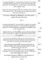
- Fig. 1a is a flow chart illustrating a method for drawing a room layout according to an exemplary embodiment. As illustrated in Fig. 1 , the method for drawing the room layout is applied in the terminal, and includes block 101 to block 103.
- a sweeping path graph of a sweeping robot is obtained, in which, the sweeping path graph includes positions of N first obstacles and shapes and positions of M second obstacles encountered by the sweeping robot when sweeping a room.
- a bottom area of the first obstacle is less than or equal to a first preset threshold, and a bottom area of the second obstacle is greater than or equal to a second preset threshold, where N and M are integers greater than or equal to 0.
- the bottom area of the first obstacle may be a contact area of the first obstacle with the ground
- the bottom area of the second obstacle may be a contact area of the second obstacle with the ground.
- the sweeping robot can determine encountered obstacle through a path obstacle avoidance function in a process of sweeping the room, and then scan the obstacle through a sensor mounted thereon to determine a relative size proportion of the obstacle with respect to the sweeping robot, and further obtain the contact area of the obstacle with the ground, that is, the bottom area of the obstacle, according to the size of the sweeping robot.
- the bottom area of the obstacle is less than or equal to the first preset threshold
- the obstacle is identified as the first obstacle.
- the bottom area of the second obstacle is greater than or equal to the second preset threshold
- the obstacle is identified as the second obstacle.
- the terminal can be connected with the sweeping robot via infrared, Bluetooth or wireless communication network, and receive the sweeping path graph sent by the sweeping robot.
- the sweeping robot may upload the sweeping path graph to a cloud server after obtaining the sweeping path graph, and the terminal can download the sweeping path graph from the cloud server when drawing the layout.
- the sweeping robot may send the sweeping path graph to another terminal after obtaining the sweeping path graph, and then this terminal forwards the sweeping path graph to the terminal that draws the layout.
- the first preset threshold and the second preset threshold may be set according to specific situations, which is not limited in embodiments of the present invention.
- the first preset threshold is less than the second preset threshold.
- Q pieces of furniture arranged in the room are determined according to the positions of the N first obstacles and the shapes and positions of the M second obstacles.
- Q is an integer greater than or equal to 0 and less than or equal to (N + M).
- the terminal can analyze the sweeping path graph after obtaining the sweeping path graph, and can obtain the positions of the N first obstacles and the shapes and positions of the M second obstacles included in the sweeping path graph.
- the first obstacle may be considered as a supporting part of the furniture, such as a table leg, a stool leg and a sofa leg.
- the positions of the N first obstacles a distance between each two first obstacles can be obtained, and then S pieces of furniture represented by the N first obstacles can be obtained.
- the bottom area of the second obstacle is big, and then the second obstacle can be considered as a piece of floor furniture, such as a floor bed, a floor table and a floor stool.
- the shapes and positions of the M second obstacles M pieces of furniture represented by the M second obstacles can be obtained.
- a sum of S and M is Q.
- the Q pieces of furniture are marked on a plan of the room to generate the layout of the room.
- the terminal can obtain the plan of the room from the cloud server or the sweeping robot, the plan only shows walls, doors, windows and floors of the room.
- the terminal determines the Q pieces of furniture arranged in the room, the terminal can mark the N first obstacles and the Q pieces of furniture represented by the M second obstacles on the plan of the room according to the positions of the N first obstacles and the shapes and positions of the M second obstacles, thus generating the layout of the room.
- the terminal can determine the furniture arranged in the cleaned room according to the sweeping path graph of the sweeping robot and the obstacles marked on the sweeping path graph, improving convenience and accuracy of drawing layout of the room, and improving user experience.
- determining Q pieces of furniture arranged in the room according to the positions of the N first obstacles and the shapes and positions of the M second obstacles can be implemented by block 1021 to block 1024.
- a distance between each first obstacle and each other first obstacle within a preset distance is obtained according to the positions of the N first obstacles.
- sizes of S closed geometries formed by the N first obstacles are obtained according to the distance between each first obstacle and each other first obstacle within the preset distance.
- sizes of M objects represented by the M second obstacles are obtained according to the shapes and positions of the M second obstacles and a size of the room.
- the Q pieces of furniture arranged in the room are determined according to the sizes of S closed geometries, the sizes of M objects and a preset furniture size database.
- the terminal can be provided with the preset distance and the preset furniture size database.
- the preset distance represents a maximum distance between respective supporting parts of most furniture
- the preset furniture size database describes various sizes of common furniture.
- the size of common bed includes 1.2 m* 2 m, 1.5 m * 2 m, or 1.8 m * 2 m
- the size of common table includes 1m * 1.8 m or 0.8 m * 1.35 m
- the size of common stool includes 0.3 m * 0.4 m or 0.5 m * 0.5 m.
- the terminal may obtain the distances between each of the N first obstacles and other first obstacles within the preset distance, and then obtain the sizes of S closed geometries formed by the N first obstacles according to the distances between each first obstacle and the other first obstacles within the preset distance.
- Supposing the terminal obtains 4 first obstacles, that is, N is 4, and the 4 first obstacles include a first obstacle A, a first obstacle B, a first obstacle C and a first obstacle D.
- the preset distance is 1.5 m, that is, the terminal can obtain the distance between each first obstacle and each other first obstacle within 1.5 m.
- the distance between each two of the first obstacle A, the first obstacle B, the first obstacle C, and the first obstacle D is less than or equal to 1.5 m, in which, the distance between the first obstacle A and the first obstacle B is 0.4 m, the distance between the first obstacle A and the first obstacle C is 0.3 m, and the distance between the first obstacle A and the first obstacle D is 0.5 m, the distance between the first obstacle B and the first obstacle D is 0.3 m, the distance between the first obstacle B and the first obstacle C is 0.5 m, the distance between the first obstacle C and the first obstacle D is 0.4m.
- the first obstacle A, the first obstacle B and the first obstacle C can form a triangle of size 0.3, 0.4 and 0.5.
- the first obstacle B, the first obstacle C and the first obstacle D can form a triangle of size 0.3, 0.4 and 0.5.
- the first obstacle A, the first obstacle C and the first obstacle D can form a triangle of size 0.3, 0.4 and 0.5.
- the first obstacle A, the first obstacle B and the first obstacle D can form a triangle of size 0.3, 0.4 and 0.5.
- the first obstacle A, the first obstacle B, the first obstacle C and the first obstacle D can form a rectangle of length and width of 0.3 and 0.4.
- the triangles and the rectangle are closed geometries, that is, S is 5.
- the sizes of the 5 closed geometries are matched with the sizes of various pieces of furniture in the preset furniture size database.
- the preset furniture size database includes the stool of the size of length and width of 0.3 and 0.4, it can be known that the closed geometry matched with the furniture is the rectangle of length and width of 0.3 and 0.4, that is, the 4 first obstacles can match one piece of furniture (the stool).
- the position of the second obstacle may be a relative position of the second obstacle in the room, that is, may include the distance between the second obstacle and each wall of the room and a ratio of the second obstacle to a length of each wall of the room. According to the shape of the second obstacle, the relative position of the second obstacle in the room and the size of the room, the size of the object represented by the second obstacle can be obtained.
- the room is rectangular, the length and width of which are 4m and 3m; the second obstacle is located at one corner of the room, the shape of the second obstacle is rectangular, a ratio of the length of the second obstacle to the length of the room is 1/2, and a ratio of the width of the second obstacle to the width of the room is 3/5, then it can be seen that the size of the object represented by the second obstacle is 2 m * 1.8 m.
- the size of the object is matched with the sizes of the various pieces of furniture in the preset furniture size database, and it can be known that the furniture matching with the size of the object is the bed.
- the terminal can determine the sizes of different objects according to the positions and/or shapes of different obstacles, and then obtain the appropriate furniture by matching according to the sizes of the objects, improving accuracy of determining the furniture.
- the multiple options of each of the Q pieces of furniture arranged in the room can be first determined and arranged according to the sizes of S closed geometries, the sizes of M objects and a preset furniture size database first. Then, a selecting operation instruction can be obtained, in which the selecting operation instruction includes a specified option of each piece of furniture determined in the plurality of options of the piece of furniture. According to the specified option of each piece of furniture, the Q pieces of furniture arranged in the room can be obtained.
- the furniture of the same size may be of multiple types or styles.
- the terminal matches the obtained sizes of objects with the preset furniture size database, it is possible to output multiple options for the furniture corresponding to each object, and display the options corresponding to each object on a terminal screen.
- the user can read the multiple options for each object, and then select one specified option satisfying the actual situation from the multiple options.
- the terminal can determine the furniture arranged in the room according to the specified option selected by the user.
- the terminal determines 3 options of the furniture according to the closed geometry of the length and width of 0.4 m * 0.3 m and the preset furniture size database, that is, a stool, a small sofa and a small table respectively, and determines 2 options of the furniture according to the object of the size of 2 m * 1.8 m and the preset furniture size database, that is, a bed and a large desk respectively.
- the preset furniture size database that is, a stool, a small sofa and a small table respectively.
- the terminal can display an original plan 100 of the room on the screen, and set images of the stool 10a, the small sofa 10b and the small table 10c around the position of the closed geometry 10 of the length and width of 0.4 m * 0.3 m, and set images of the bed 20a and the large desk 20b around the position of the object of the size of 2 m * 1.8 m.
- the user can select the specified option of the closed geometry 10 from the stool 10a, the small sofa 10b and the small table 10c. For example, the user selects the stool 10a as the furniture corresponding to the closed geometry 10 according to actual situation of the room, and then the user can click the image of the stool 10a.
- the terminal may use the stool 10a as the specified option of the furniture corresponding to the closed geometry 10 after detecting the click.
- the user selects the bed 20a as the furniture corresponding to the object of the size of 2 m * 1.8 m according to the actual situation of the room, and then the user can click the image of the bed 20a.
- the terminal may use the bed 20a as the specified option of the furniture corresponding to the object of the size of 2m * 1.8 m after detecting the click.
- the terminal can determine the two pieces of furniture arranged in the room as the stool and the bed.
- the terminal can draw the layout of the room. As illustrated in Fig. Id, according to the position of the closed geometry 10, the stool 10a is marked on the plan 100 of the room, and according to the position of the object 20, the bed 20a is marked on the plan 100 of the room. Thus, the layout of the room can be obtained.
- the terminal when determining multiple options of the furniture according to the size of the object, can display the multiple options on the screen to facilitate the user to select the specified option of the furniture corresponding to the object from the multiple options, thus improving flexibility and accuracy of drawing the layout, and improving user experience.
- the method further includes block 104 and block 105.
- the Q pieces of furniture arranged in the room are drawn on the panoramic scene picture, and a panoramic layout of the room is obtained.
- the terminal can obtain multiple pictures of the room by adjusting a shooting angle and a focal length of a camera, and then obtain the panoramic scene picture of the room by synthesizing the multiple pictures.
- the panoramic scene picture can wholly reflect an environment of the room in a surrounding angle.
- the Q pieces of furniture arranged in the room are drawn on the panoramic scene picture to obtain the panoramic layout of the room.
- the panoramic layout can also wholly reflect the furniture arranged in the room in a surrounding angle, improving an appreciation of the layout.
- the terminal can display the determined Q pieces of furniture on the panoramic scene picture of the room, improving an appreciation of the layout, and improving user experience.
- Fig. 2 is a flow chart illustrating a method for drawing a room layout according to an exemplary embodiment. As illustrated in Fig. 2 , the method for drawing the room layout is applied in the sweeping robot, including block 201 and block 202.
- positions of N first obstacles and shapes and positions of M second obstacles encountered when sweeping a room are marked on a sweeping path graph.
- a bottom area of the first obstacle is less than or equal to a first preset threshold, and a bottom area of the second obstacle is greater than or equal to a second preset threshold, where N and M are integers greater than or equal to 0.
- the sweeping robot may encounter multiple obstacles during sweeping the room.
- Some obstacles are fixed obstacles, such as an edge of the furniture, or a supporting part of the furniture.
- Some obstacles are movable obstacles, such as feet of the user, or legs of a pet.
- the sweeping robot can determine the number of times of encountering the obstacle first before marking the obstacle. When the number of times of encountering the obstacle at the same position is large, it indicates that the obstacle is the fixed obstacle and can be marked on the sweeping path graph.
- the sweeping robot may be provided with a counter corresponding to the reference obstacle. Each time encountering the reference obstacle, the sweeping robot instructs the counter to add 1, and determines whether data recorded in the counter is greater than or equal to the preset number of times. When the data recorded in the counter is greater than or equal to the preset number of times, it indicates that the number of times the sweeping robot encounters the reference obstacle is great, and the reference obstacle can be considered as the fixed obstacle. At this time, the sweeping robot can obtain the bottom area of the reference obstacle.
- the shape and position of the reference obstacle can be obtained according to scanned image, and the reference obstacle may be marked on the sweeping path graph in a form of the second obstacle.
- the bottom area of the reference obstacle is small, that is, is less than or equal to the first preset threshold, the position of the reference obstacle can be obtained according to the scanned image, and the reference obstacle may be marked on the sweeping path graph in a form of the first obstacle.
- the sweeping robot can estimate the length and width of the bottom of the reference obstacle according to the scanned image, and then obtain the bottom area of the reference obstacle.
- the bottom area of the first obstacle may be the contact area of the first obstacle with the ground
- the bottom area of the second obstacle may be the contact area of the second obstacle with the ground.
- the first preset threshold and the second preset threshold may be set according to the specific situations, which are not limited in embodiments of the present invention. Alternatively, the first preset threshold is less than the second preset threshold.
- the sweeping path graph marked with the positions of the N first obstacles and the shapes and positions of the M second obstacles is sent to a terminal.
- the sweeping robot may be connected with the terminal via infrared, Bluetooth, or wireless communication networks.
- the sweeping path graph can be sent to the terminal through the connection path to facilitate the terminal to draw the layout of the room.
- the sweeping robot can mark the obstacles encountered in sweeping the room on the sweeping path graph, and send the sweeping path graph to the terminal to facilitate the terminal to draw the layout of the room, improving convenience and accuracy of drawing layout of the room, and improving user experience.
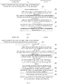
- Fig. 3 is an interaction diagram illustrating a method for drawing a room layout according to an exemplary embodiment. As illustrated in Fig. 3 , the method includes following block 301 to block 307.
- the sweeping robot marks the positions of N first obstacles and shapes and the positions of M second obstacles encountered when sweeping a room on a sweeping path graph.
- the sweeping robot sends the sweeping path graph marked with the positions of the N first obstacles and the shapes and positions of the M second obstacles to a terminal.
- the terminal obtains a distance between each first obstacle and each other first obstacle within a preset distance according to the positions of the N first obstacles.
- the terminal obtains sizes of S closed geometries formed by the N first obstacles according to the distance between other first obstacles within the preset distance and the each first obstacle.
- the terminal determines sizes of M objects represented by the M second obstacles according to the shapes and positions of the M second obstacles and a size of the room.
- the terminal determines the Q pieces of furniture arranged in the room according to the sizes of S closed geometries, the sizes of M objects and a preset furniture size database.
- the terminal marks the Q pieces of furniture on the plan of the room to generate the layout of the room.
- the terminal can determine the furniture arranged in the cleaned room according to the sweeping path graph sent by the sweeping robot and the obstacles marked on the sweeping path graph, improving convenience and accuracy of drawing the layout of the room, and improving user experience.
- Fig. 4 is an interaction diagram illustrating a method for drawing a room layout according to an exemplary embodiment. As illustrated in Fig. 4 , the method includes block 401 to block 410.
- the sweeping robot marks the positions of N first obstacles and shapes and the positions of M second obstacles encountered when sweeping a room on a sweeping path graph.
- the sweeping robot sends the sweeping path graph marked with the positions of the N first obstacles and the shapes and positions of the M second obstacles to a terminal.
- the terminal obtains a distance between each first obstacle and each other first obstacle within a preset distance according to the positions of the N first obstacles.
- the terminal obtains sizes of S closed geometries formed by the N first obstacles according to the distance between each first obstacle and each other first obstacle within the preset distance.
- the terminal determines sizes of M objects represented by the M second obstacles according to the shapes and positions of the M second obstacles and a size of the room.
- the terminal determines and displays multiple options of each of the Q pieces of furniture arranged in the room according to the sizes of S closed geometries, the sizes of M objects and the preset furniture size database.
- the terminal obtains a selecting operation instruction, in which the selecting operation instruction includes a specified option of each piece of furniture determined in the plurality of options of the piece of furniture.
- the terminal determines the Q pieces of furniture arranged in the room according to the specified option of each piece of furniture.
- the terminal obtains a panoramic scene picture of the room.
- the terminal draws the Q pieces of furniture arranged in the room on the panoramic scene picture to obtain a panoramic layout of the room.
- the terminal can determine the furniture arranged in the cleaned room according to the sweeping path graph sent by the sweeping robot and the obstacles marked on the sweeping path graph, improving convenience and accuracy of drawing the layout of the room, and improving user experience.
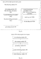
- Fig. 5a is a block diagram illustrating a device 50 for drawing a room layout according to an exemplary embodiment.
- the device 50 may be implemented as part or all of an electronic device by software, hardware, or a combination thereof.
- the device 50 for drawing the room layout includes a first obtaining module 501, a determining module 502 and a generating module 503.
- the first obtaining module 501 is configured to obtain a sweeping path graph of a sweeping robot.
- the sweeping path graph includes positions of N first obstacles and shapes and positions of M second obstacles encountered by the sweeping robot when sweeping a room.
- a bottom area of the first obstacle is less than or equal to a first preset threshold, and a bottom area of the second obstacle is greater than or equal to a second preset threshold, where N and M are integers greater than or equal to 0.
- the determining module 502 is configured to determine Q pieces of furniture arranged in the room according to the positions of the N first obstacles and the shapes and positions of the M second obstacles, where Q is an integer greater than or equal to 0 and less than or equal to (N + M).
- the generating module 503 is configured to mark the Q pieces of furniture on a plan of the room to generate the layout of the room.
- the first preset threshold is less than the second preset threshold.
- the determining module 502 includes a first obtaining sub-module 5021, a second obtaining sub-module 5022, a first determining sub-module 5023, and a second determining sub-module 5024.
- the first obtaining sub-module 5021 is configured to obtain a distance between each first obstacle and each other first obstacle within a preset distance according to the positions of the N first obstacles.
- the second obtaining sub-module 5022 is configured to obtain sizes of S closed geometries formed by the N first obstacles according to the distance between each first obstacle and each other first obstacle within the preset distance.
- the first determining sub-module 5023 is configured to determine sizes of M objects represented by the M second obstacles according to the shapes and positions of the M second obstacles and a size of the room.
- the second determining sub-module 5024 is configured to determine the Q pieces of furniture arranged in the room according to the sizes of S closed geometries, the sizes of M objects and a preset furniture size database.
- the second determining sub-module 5024 includes a determining and displaying unit 5024a, a receiving unit 5024b, and a determining unit 5024c.
- the determining and displaying unit 5024a is configured to determine and display a plurality of options of each of the Q pieces of furniture arranged in the room according to the sizes of S closed geometries, the sizes of M objects and the preset furniture size database.
- the receiving unit 5024b is configured to obtain a selecting operation instruction, the selecting operation instruction including a specified option of each piece of furniture determined in the plurality of options of the piece of furniture.
- the determining unit 5024c is configured to determine the Q pieces of furniture arranged in the room according to the specified option of each piece of furniture.
- the device 50 further includes a second obtaining module 504 and a third obtaining module 505.
- the second obtaining module 504 is configured to obtain a panoramic scene picture of the room.
- the third obtaining module 505 is configured to draw the Q pieces of furniture arranged in the room on the panoramic scene picture to obtain a panoramic layout of the room.
- Embodiments of the present invention provide a device for drawing the layout of the room, which can determine the furniture arranged in the cleaned room according to the sweeping path graph sent by the sweeping robot and the obstacles marked on the sweeping path graph, improving convenience and accuracy of drawing the layout of the room, and improving user experience.
- Fig. 6a is a block diagram illustrating a device 60 for drawing a room layout according to an exemplary embodiment.
- the device 60 may be implemented as part or all of an electronic device by software, hardware, or a combination thereof.
- the device 60 for drawing the room layout includes a marking module 601 and a sending module 602.
- the marking module 601 is configured to mark positions of N first obstacles and shapes and positions of M second obstacles encountered when sweeping a room on a sweeping path graph.
- a bottom area of the first obstacle is less than or equal to a first preset threshold, and a bottom area of the second obstacle is greater than or equal to a second preset threshold ,where N and M are integers greater than or equal to 0.
- the sending module 602 is configured to send the sweeping path graph marked with the positions of the N first obstacles and the shapes and positions of the M second obstacles to a terminal.
- the first preset threshold is less than the second preset threshold.
- the marking module 601 includes a third obtaining sub-module 6011, a first marking sub-module 6012 and a second marking sub-module 6013.
- the third obtaining sub-module 6011 is configured to obtain a bottom area of a reference obstacle when the number of times of encountering the reference obstacle when sweeping the room is greater than or equal to the preset number of times.
- the first marking sub-module 6012 is configured to, when the bottom area of the reference obstacle is less than or equal to the first preset threshold, mark the reference obstacle as the first obstacle on the sweeping path graph according to a position of the reference obstacle.
- the second marking sub-module 6013 is configured to, when the bottom area of the reference obstacle is greater than or equal to the second preset threshold, mark the reference obstacle as the second obstacle on the sweeping path graph according to a shape of the reference obstacle and the position of the reference obstacle.
- Embodiments of the present invention provide a device for drawing the layout of the room, which can marks the obstacles encountered when sweeping the room on the sweeping path graph and sends the sweeping path graph to the terminal, such that the terminal can draw the layout of the room, thus improving convenience and accuracy of drawing the layout of the room, and improving user experience.
- Embodiments of the present invention provides a device for drawing a room layout, and the device for drawing the room layout includes a first processor and a first memory.
- the first memory is configured to store instructions executable by the first processor.
- the first processor is configured to: obtain a sweeping path graph of a sweeping robot, the sweeping path graph including positions of N first obstacles and shapes and positions of M second obstacles encountered by the sweeping robot when sweeping a room, a bottom area of the first obstacle being less than or equal to a first preset threshold, and a bottom area of the second obstacle being greater than or equal to a second preset threshold, where N and M are integers greater than or equal to 0; determine Q pieces of furniture arranged in the room according to the positions of the N first obstacles and the shapes and positions of the M second obstacles, where Q is an integer greater than or equal to 0 and less than or equal to (N + M); and mark the Q pieces of furniture on a plan of the room to generate the layout of the room.
- the first preset threshold is less than the second preset threshold.
- the first processor is further configured to obtain a distance between each first obstacle and each other first obstacle within a preset distance according to the positions of the N first obstacles; obtain sizes of S closed geometries formed by the N first obstacles according to the distance between each first obstacle and each other first obstacle within the preset distance; determine sizes of M objects represented by the M second obstacles according to the shapes and positions of the M second obstacles and a size of the room; and determine the Q pieces of furniture arranged in the room according to the sizes of S closed geometries, the sizes of M objects and a preset furniture size database.
- the first processor is further configured to: determine and display a plurality of options of each of the Q pieces of furniture arranged in the room according to the sizes of S closed geometries, the sizes of M objects and the preset furniture size database; obtain a selecting operation instruction, the selecting operation instruction including a specified option of each piece of furniture determined in the plurality of options of each piece of furniture; and determine the Q pieces of furniture arranged in the room according to the specified option of each piece of furniture.
- the first processor is further configured to: obtain a panoramic scene picture of the room; and draw the Q pieces of furniture arranged in the room on the panoramic scene picture to obtain a panoramic layout of the room.
- the device can determine the furniture arranged in the cleaned room according to the sweeping path graph sent by the sweeping robot and the obstacles marked on the sweeping path graph, improving convenience and accuracy of drawing the layout of the room, and improving user experience.
- Embodiments of the present invention provide a device for drawing a room layout, and the device for drawing the room layout includes a second processor and a second memory.
- the second memory is configured to store instructions executable by the second processor.
- the second processor is configured to: mark positions of N first obstacles and shapes and positions of M second obstacles encountered when sweeping a room on a sweeping path graph, a bottom area of the first obstacle being less than or equal to a first preset threshold, and a bottom area of the second obstacle being greater than or equal to a second preset threshold, where N and M are integers greater than or equal to 0; and send the sweeping path graph marked with the positions of the N first obstacles and the shapes and positions of the M second obstacles to a terminal.
- the first preset threshold is less than the second preset threshold.
- the second processor is further configured to obtain a bottom area of a reference obstacle when the number of times of encountering the reference obstacle when sweeping the room is greater than or equal to the preset number of times; when the bottom area of the reference obstacle is less than or equal to the first preset threshold, mark the reference obstacle as the first obstacle on the sweeping path graph according to a position of the reference obstacle; and when the bottom area of the reference obstacle is greater than or equal to the second preset threshold, mark the reference obstacle as the second obstacle on the sweeping path graph according to a shape of the reference obstacle and the position of the reference obstacle.
- the device can mark the obstacles encountered when sweeping the room on the sweeping path graph and send the sweeping path graph to the terminal, such that the terminal can draw the layout of the room, improving convenience and accuracy of drawing the layout of the room, and improving user experience.
- Fig. 7 is a schematic diagram illustrating a device 70 for drawing a room layout according to an exemplary embodiment.
- the device 70 is applicable to a terminal device.
- the device 70 may be a mobile phone, a computer, a digital broadcasting terminal, a message transceiver device, a game console, a tablet device, a medical device, a fitness device and a personal digital assistant.
- the device 70 may include one or more of the following components: a processing component 702, a memory 704, a power component 706, a multimedia component 707, an audio component 710, an input/output (I/O) interface 712, a sensor component 714, and a communication component 716.
- the processing component 702 typically controls overall operations of the device 70, such as the operations associated with display, telephone calls, data communications, camera operations, and recording operations.
- the processing component 702 may include one or more processors 720 to execute instructions to perform all or part of the steps in the above described methods.
- the processing component 702 may include one or more modules which facilitate the interaction between the processing component 702 and other components.
- the processing component 702 may include a multimedia module to facilitate the interaction between the multimedia component 708 and the processing component 702.
- the memory 704 is configured to store various types of data to support the operation of the device 70. Examples of such data include instructions for any applications or methods operated on the device 70, contact data, phonebook data, messages, pictures, video, etc.
- the memory 704 may be implemented using any type of volatile or non-volatile memory devices, or a combination thereof, such as a static random access memory (SRAM), an electrically erasable programmable read-only memory (EEPROM), an erasable programmable read-only memory (EPROM), a programmable read-only memory (PROM), a read-only memory (ROM), a magnetic memory, a flash memory, a magnetic or optical disk.
- SRAM static random access memory
- EEPROM electrically erasable programmable read-only memory
- EPROM erasable programmable read-only memory
- PROM programmable read-only memory
- ROM read-only memory
- magnetic memory a magnetic memory
- flash memory a flash memory
- magnetic or optical disk a magnetic or optical
- the power component 706 provides power to various components of the device 70.
- the power component 706 may include a power management system, one or more power sources, and any other components associated with the generation, management, and distribution of power in the device 70.
- the multimedia component 708 includes a screen providing an output interface between the device 70 and the user.
- the screen may include a liquid crystal display (LCD) and a touch panel (TP). If the screen includes the touch panel, the screen may be implemented as a touch screen to receive input signals from the user.
- the touch panel includes one or more touch sensors to sense touches, swipes, and gestures on the touch panel. The touch sensors may not only sense a boundary of a touch or swipe action, but also sense a period of time and a pressure associated with the touch or swipe action.
- the multimedia component 708 includes a front-facing camera and / or a rear-facing camera.
- the front-facing camera and / or the rear-facing camera can receive external multimedia data.
- Each front-facing camera and rear-facing camera may be a fixed optical lens system or has focal length and optical zoom capability.
- the audio component 710 is configured to output and/or input audio signals.
- the audio component 710 includes a microphone ("MIC") configured to receive an external audio signal when the device 70 is in an operation mode, such as a call mode, a recording mode, and a voice recognition mode.
- the received audio signal may be further stored in the memory 704 or transmitted via the communication component 716.
- the audio component 710 further includes a speaker to output audio signals.
- the I/O interface 712 provides an interface between the processing component 702 and peripheral interface modules, such as a keyboard, a click wheel, buttons, and the like.
- the buttons may include, but are not limited to, a home button, a volume button, a starting button, and a locking button.
- the sensor component 714 includes one or more sensors to provide status assessments of various aspects of the device 70. For instance, the sensor component 714 may detect an open/closed status of the device 70, relative positioning of components, e.g., the display and the keypad, of the device 70, a change in position of the device 70 or a component of the device 70, a presence or absence of user contact with the device 70, an orientation or an acceleration/deceleration of the device 70, and a change in temperature of the device 70.
- the sensor component 714 may include a proximity sensor configured to detect the presence of nearby objects without any physical contact.
- the sensor component 714 may also include a light sensor, such as a CMOS or CCD image sensor, for use in imaging applications.
- the sensor component 714 may also include an accelerometer sensor, a gyroscope sensor, a magnetic sensor, a pressure sensor, or a temperature sensor.
- the communication component 716 is configured to facilitate communication, wired or wirelessly, between the device 70 and other devices.
- the device 70 can access a wireless network based on a communication standard, such as WiFi, 2G, or 3G, or a combination thereof.
- the communication component 716 receives a broadcast signal or broadcast associated information from an external broadcast management system via a broadcast channel.
- the communication component 716 further includes a near field communication (NFC) module to facilitate short-range communications.
- the NFC module may be implemented based on a radio frequency identification (RFID) technology, an infrared data association (IrDA) technology, an ultra-wideband (UWB) technology, a Bluetooth (BT) technology, and other technologies.
- RFID radio frequency identification
- IrDA infrared data association
- UWB ultra-wideband
- BT Bluetooth
- the device 70 may be implemented with one or more application specific integrated circuits (ASICs), digital signal processors (DSPs), digital signal processing devices (DSPDs), programmable logic devices (PLDs), field programmable gate arrays (FPGAs), controllers, micro-controllers, microprocessors, or other electronic components, for performing the above described methods.
- ASICs application specific integrated circuits
- DSPs digital signal processors
- DSPDs digital signal processing devices
- PLDs programmable logic devices
- FPGAs field programmable gate arrays
- controllers micro-controllers, microprocessors, or other electronic components, for performing the above described methods.
- non-transitory computer-readable storage medium including instructions, such as included in the memory 704, executable by the processor 720 in the device 70, for performing the above-described methods.
- the non-transitory computer-readable storage medium may be a ROM, a RAM, a CD-ROM, a magnetic tape, a floppy disc, an optical data storage device, and the like.
- Fig. 8 is a schematic diagram illustrating a device 80 for drawing a room layout according to another exemplary embodiment.
- the device 80 includes a processing component 802, and the processing component 802 further includes one or more processors and a memory resource represented by a memory 803.
- the memory resource is configured to store instructions executable by the processing component 802, such as application programs.
- the application program stored in the memory 803 may include one or more modules corresponding to a set of instructions.
- the processing component 802 is configured to execute instructions to execute the method illustrated in Fig. 2 .
- the device further includes a power component 806 configured to execute power management of the device 80, a wired or wireless network interface 805 configured to connect the device 80 to the network, and an input/output (I/O) interface 808.
- the device 80 may operate based on an operating system stored in the memory 803, such as Windows Server TM, Mac OS XTM, Unix TM, Linux TM, Free BSDTM, or the like.
- Embodiments of the present invention provide a non-transitory computer readable storage medium.
- the device 70 can execute the method for drawing a room layout in the terminal side.
- the method includes: obtaining a sweeping path graph of a sweeping robot, the sweeping path graph including positions of N first obstacles and shapes and positions of M second obstacles encountered by the sweeping robot when sweeping a room, a bottom area of the first obstacle being less than or equal to a first preset threshold, and a bottom area of the second obstacle being greater than or equal to a second preset threshold, where N and M are integers greater than or equal to 0; determining Q pieces of furniture arranged in the room according to the positions of the N first obstacles and the shapes and positions of the M second obstacles, where Q is an integer greater than or equal to 0 and less than or equal to (N + M); and marking the Q pieces of furniture on a plan of the room to generate the layout of the room.
- the first preset threshold is less than the second preset threshold.
- determining Q pieces of furniture arranged in the room according to the positions of the N first obstacles and the shapes and positions of the M second obstacles includes: obtaining a distance between each first obstacle and each other first obstacle within a preset distance according to the positions of the N first obstacles; obtaining sizes of S closed geometries formed by the N first obstacles according to the distance between each first obstacle and each other first obstacle within the preset distance; determining sizes of M objects represented by the M second obstacles according to the shapes and positions of the M second obstacles and a size of the room; and determining the Q pieces of furniture arranged in the room according to the sizes of S closed geometries, the sizes of M objects and a preset furniture size database.
- determining the Q pieces of furniture arranged in the room according to the sizes of S closed geometries, the sizes of M objects and a preset furniture size database includes: determining and displaying a plurality of options of each of the Q pieces of furniture arranged in the room according to the sizes of S closed geometries, the sizes of M objects and the preset furniture size database; obtaining a selecting operation instruction, the selecting operation instruction including a specified option of each piece of furniture determined in the plurality of options of each piece of furniture; and determining the Q pieces of furniture arranged in the room according to the specified option of each piece of furniture.
- the method further includes: obtaining a panoramic scene picture of the room; and drawing the Q pieces of furniture arranged in the room on the panoramic scene picture to obtain a panoramic layout of the room.
- Embodiments of the present invention provide another non-transitory computer readable storage medium.
- the device 80 can execute the method for drawing a room layout in the robot side.
- the method includes: marking positions of N first obstacles and shapes and positions of M second obstacles encountered when sweeping a room on a sweeping path graph, a bottom area of the first obstacle being less than or equal to a first preset threshold, and a bottom area of the second obstacle being greater than or equal to a second preset threshold, where N and M are integers greater than or equal to 0; and sending the sweeping path graph marked with the positions of the N first obstacles and the shapes and positions of the M second obstacles to a terminal.
- the first preset threshold is less than the second preset threshold.
- marking positions of N first obstacles and shapes and positions of M second obstacles encountered when sweeping a room on a sweeping path graph includes: obtaining a bottom area of a reference obstacle when the number of times of encountering the reference obstacle when sweeping the room is greater than or equal to the preset number of times; when the bottom area of the reference obstacle is less than or equal to the first preset threshold, marking the reference obstacle as the first obstacle on the sweeping path graph according to a position of the reference obstacle; and when the bottom area of the reference obstacle is greater than or equal to the second preset threshold, marking the reference obstacle as the second obstacle on the sweeping path graph according to a shape of the reference obstacle and the position of the reference obstacle.
- modules, sub-modules, unit, and components in the present invention can be implemented using any suitable technology.
- a module may be implemented using circuitry, such as an integrated circuit (IC).
- IC integrated circuit
- a module may be implemented as a processing circuit executing software instructions.
Landscapes
- Engineering & Computer Science (AREA)
- Radar, Positioning & Navigation (AREA)
- Remote Sensing (AREA)
- Physics & Mathematics (AREA)
- General Physics & Mathematics (AREA)
- Automation & Control Theory (AREA)
- Aviation & Aerospace Engineering (AREA)
- Theoretical Computer Science (AREA)
- Business, Economics & Management (AREA)
- Multimedia (AREA)
- Human Resources & Organizations (AREA)
- Economics (AREA)
- Strategic Management (AREA)
- Quality & Reliability (AREA)
- Game Theory and Decision Science (AREA)
- Entrepreneurship & Innovation (AREA)
- Marketing (AREA)
- Operations Research (AREA)
- Development Economics (AREA)
- Tourism & Hospitality (AREA)
- General Business, Economics & Management (AREA)
- Processing Or Creating Images (AREA)
- Control Of Position, Course, Altitude, Or Attitude Of Moving Bodies (AREA)
- Instructional Devices (AREA)
- Electric Vacuum Cleaner (AREA)
Abstract
Description
- The present invention relates to the field of data processing technology, and more particularly, to a method and a device for drawing a room layout.
- With rapid development of science and technology, more and more intelligent household appliances are introduced to millions of households, greatly improving comfort and convenience for people. For example, in order to reduce labors of sweeping a room, more and more people select to use a sweeping robot to sweep the room.
- In the related art, in order to avoid furniture arranged in the room, the sweeping robot can scan an area that needs to be cleaned by infrared or ultrasonic to detect furniture that appears in a sweeping path. When sweeping the room, the sweeping robot can automatically turn when encountering the furniture, thus avoiding colliding with the furniture during a sweeping process.
- In order to solve the problems in the related art, embodiments of the present invention provide a method and a device for drawing a room layout. Technical solutions are as follows.
- According to a first aspect of embodiments of the present invention, there is provided a method for drawing a room layout, including: obtaining a sweeping path graph of a sweeping robot, the sweeping path graph including positions of N first obstacles and shapes and positions of M second obstacles encountered by the sweeping robot when sweeping a room, a bottom area of each of the N first obstacles being less than or equal to a first preset threshold, and a bottom area of each of the M second obstacles being greater than or equal to a second preset threshold, where N and M are integers greater than or equal to 0; determining Q pieces of furniture arranged in the room based on the positions of the N first obstacles and the shapes and the positions of the M second obstacles, where Q is an integer greater than or equal to 0 and less than or equal to (N + M); and marking the Q pieces of furniture on a plan of the room to generate the layout of the room.
- The technical solutions provided in embodiments of the present invention may have following advantageous effects. Based on the sweeping path graph of the sweeping robot and the obstacles marked on the sweeping path graph, the furniture arranged in the room can be determined, improving convenience and accuracy of drawing the layout of the room, and further improving user experience.
- In an embodiment, the first preset threshold is less than the second preset threshold.
- The technical solutions provided in embodiments of the present invention may have following advantageous effects. By defining the bottom area, obstacles of different categories can be determined, improving accuracy of determining the furniture arranged in the room based on the obstacles, and further improving user experience.
- In an embodiment, determining the Q pieces of furniture arranged in the room based on the positions of the N first obstacles and the shapes and the positions of the M second obstacles includes: obtaining a distance between each of the N first obstacles within a preset distance based on the positions of the N first obstacles; obtaining sizes of S closed geometries formed by the N first obstacles based on the distances between each of the N first obstacles within the preset distance; determining sizes of M objects represented by the M second obstacles based on the shapes and the positions of the M second obstacles and a size of the room; and determining the Q pieces of furniture arranged in the room based on the sizes of the S closed geometries, the sizes of the M objects, and a preset furniture size database.
- The technical solutions provided in embodiments of the present invention may have following advantageous effects. Based on the positions and/or shapes of different obstacles, sizes of different objects can be determined, and then appropriate furniture can be obtained by matching according to the sizes of the objects, improving accuracy of determining the furniture.
- In an embodiment, determining the Q pieces of furniture arranged in the room based on the sizes of the S closed geometries, the sizes of the M objects, and the preset furniture size database includes: determining and displaying a plurality of options of respective furniture of the Q pieces of furniture arranged in the room based on the sizes of the S closed geometries, the sizes of the M objects, and the preset furniture size database; receiving a selecting operation instruction, the selecting operation instruction including a specified option of each piece of furniture determined in the plurality of options of each piece of furniture; and determining the Q pieces of furniture arranged in the room based on the specified option of each piece of furniture.
- The technical solutions provided in embodiments of the present invention may have following advantageous effects. When there are multiple options of furniture determined based on to the size of the object, the multiple options can be displayed on a screen to facilitate the user to select a specified option of the furniture corresponding to the object from the multiple options, improving flexibility and accuracy of drawing the layout, and improving user experience.
- In an embodiment, the method further includes: obtaining a panoramic scene picture of the room; and drawing the Q pieces of furniture arranged in the room on the panoramic scene picture to obtain a panoramic layout of the room.
- The technical solutions provided in embodiments of the present invention may have following advantageous effects. The determined Q pieces of furniture can be drawn on the panoramic scene picture of the room for display, thus improving an appreciation of the layout, and improving user experience.
- According to a second aspect of embodiments of the present invention, there is provided a method for drawing a room layout, including: marking positions of N first obstacles and shapes and positions of M second obstacles encountered when sweeping a room on a sweeping path graph, a bottom area of each of the N first obstacles being less than or equal to a first preset threshold, and a bottom area of each of the M second obstacles being greater than or equal to a second preset threshold, where N and M are integers greater than or equal to 0; and sending the sweeping path graph marked with the positions of the N first obstacles and the shapes and positions of the M second obstacles to a terminal.
- The technical solutions provided in embodiments of the present invention may have following advantageous effects. The sweeping robot can mark the obstacles encountered in sweeping the room on the sweeping path graph, and send the sweeping path graph to the terminal, such that the terminal can draw the layout of the room, thus improving convenience and accuracy for drawing the layout of the room, and improving user experience.
- In an embodiment, the first preset threshold is less than the second preset threshold.
- The technical solutions provided in embodiments of the present invention may have following advantageous effects. By defining the bottom area, the sweeping robot can determine obstacles of different categories, improving accuracy of the terminal determining the furniture arranged in the room based on the obstacles, and improving user experience.
- In an embodiment, marking the positions of the N first obstacles and the shapes and the positions of the M second obstacles encountered when sweeping the room on the sweeping path graph includes: obtaining a bottom area of a reference obstacle when the number of times of encountering the reference obstacle when sweeping the room is greater than or equal to the preset number of times; when the bottom area of the reference obstacle is less than or equal to the first preset threshold, marking the reference obstacle as one of the N first obstacles on the sweeping path graph based on a position of the reference obstacle; and when the bottom area of the reference obstacle is greater than or equal to the second preset threshold, marking the reference obstacle as one of the M second obstacles on the sweeping path graph based on a shape of the reference obstacle and the position of the reference obstacle.
- The technical solutions provided in embodiments of the present invention may have following advantageous effects. When a same obstacle is frequently encountered during a sweeping process, the obstacle may be marked as one first obstacle or one second obstacle, avoiding an error of drawing the layout caused by wrongly marking a moving object, and improving an accuracy of drawing the layout.
- According to a third aspect of embodiments of the present invention, there is provided a device for drawing a room layout, including a first obtaining module, a determining module and a generating module.
- The first obtaining module is configured to obtain a sweeping path graph of a sweeping robot, the sweeping path graph including positions of N first obstacles and shapes and positions of M second obstacles encountered by the sweeping robot when sweeping a room, a bottom area of each of the N first obstacles being less than or equal to a first preset threshold, and a bottom area of each of the M second obstacles being greater than or equal to a second preset threshold, where N and M are integers greater than or equal to 0.
- The determining module is configured to determine Q pieces of furniture arranged in the room based on the positions of the N first obstacles and the shapes and the positions of the M second obstacles, where Q is an integer greater than or equal to 0 and less than or equal to (N + M).
- The generating module is configured to mark the Q pieces of furniture on a plan of the room to generate the layout of the room.
- In an embodiment, the first preset threshold is less than the second preset threshold.
- In an embodiment, the determining module includes a first obtaining sub-module, a second obtaining sub-module, a first determining sub-module and a second determining sub-module.
- The first obtaining sub-module is configured to obtain a distance between each of the N first obstacles within a preset distance based on the positions of the N first obstacles.
- The second obtaining sub-module is configured to obtain sizes of S closed geometries formed by the N first obstacles based on the distances between each of the N first obstacles within the preset distance.
- The first determining sub-module is configured to determine sizes of M objects represented by the M second obstacles based on the shapes and the positions of the M second obstacles and a size of the room.
- The second determining sub-module is configured to determine the Q pieces of furniture arranged in the room based on the sizes of the S closed geometries, the sizes of the M objects, and a preset furniture size database.
- In an embodiment, the second determining sub-module includes a determining and displaying unit, a receiving unit and a determining unit.
- The determining and displaying unit is configured to determine and display a plurality of options for each piece of furniture arranged in the room based on the sizes of the S closed geometries, the sizes of the M objects, and the preset furniture size database.
- The receiving unit is configured to receive a selecting operation instruction, the selecting operation instruction including a specified option of each piece of furniture determined in the plurality of options of the piece of furniture.
- The determining unit is configured to determine the Q pieces of furniture arranged in the room based on the specified option of each piece of furniture.
- In an embodiment, the device further includes a second obtaining module and a third obtaining module.
- The second obtaining module is configured to obtain a panoramic scene picture of the room.
- The third obtaining module is configured to draw the Q pieces of furniture arranged in the room on the panoramic scene picture to obtain a panoramic layout of the room.
- According to a fourth aspect of embodiments of the present invention, there is provided a device for drawing a room layout, including a marking module and a sending module.
- The marking module is configured to mark positions of N first obstacles and shapes and positions of M second obstacles encountered when sweeping a room on a sweeping path graph, a bottom area of each of the N first obstacles being less than or equal to a first preset threshold, and a bottom area of each of the M second obstacles being greater than or equal to a second preset threshold, where N and M are integers greater than or equal to 0.
- The sending module is configured to send the sweeping path graph marked with the positions of the N first obstacles and the shapes and the positions of the M second obstacles to a terminal.
- In an embodiment, the first preset threshold is less than the second preset threshold.
- In an embodiment, the marking module includes a third obtaining sub-module, a first marking sub-module and a second marking sub-module.
- The third obtaining sub-module is configured to obtain a bottom area of a reference obstacle when the number of times of encountering the reference obstacle when sweeping the room is greater than or equal to the preset number of times.
- The first marking sub-module is configured to, when the bottom area of the reference obstacle is less than or equal to the first preset threshold, mark the reference obstacle as one of the N first obstacles on the sweeping path graph based on a position of the reference obstacle.
- The second marking sub-module is configured to, when the bottom area of the reference obstacle is greater than or equal to the second preset threshold, mark the reference obstacle as one of the M second obstacles on the sweeping path graph based on a shape of the reference obstacle and the position of the reference obstacle.
- According to a fifth aspect of embodiments of the present invention, there is provided a device for drawing a room layout, including a processor and a memory.
- The memory is configured to store instructions executable by the processor.
- The processor is configured to perform a method for drawing a room layout according to embodiments of the present invention.
- According to a sixth aspect of embodiments of the present invention, there is provided a computer program comprising instructions executable by a processor, which when executed by the processor cause the processor to perform a method for drawing a room layout according to embodiments of the present invention, and a computer-readable storage medium comprising such a computer program.
- It is to be understood that both the foregoing general description and the following detailed description are exemplary and explanatory only and are not restrictive of the present invention, as claimed.
- The accompanying drawings, which are incorporated in and constitute a part of this specification, illustrate embodiments consistent with the present invention and, together with the description, serve to explain the principles of the present invention.
-
Fig. 1a is a flow chart illustrating a method for drawing a room layout according to an exemplary embodiment. -
Fig. 1b is a flow chart illustrating a method for drawing a room layout according to an exemplary embodiment. -
Fig. 1c is a room layout diagram displayed with furniture options according to an exemplary embodiment. -
Fig. 1d is a room layout diagram according to an exemplary embodiment. -
Fig. 1e is a flow chart illustrating a method for drawing a room layout according to an exemplary embodiment. -
Fig. 2 is a flow chart illustrating a method for drawing a room layout according to an exemplary embodiment. -
Fig. 3 is an interaction diagram illustrating a method for drawing a room layout according to an exemplary embodiment. -
Fig. 4 is an interaction diagram illustrating a method for drawing a room layout according to an exemplary embodiment. -
Fig. 5a is a block diagram illustrating a device for drawing a room layout according to an exemplary embodiment. -
Fig. 5b is a block diagram illustrating a device for drawing a room layout according to an exemplary embodiment. -
Fig. 5c is a block diagram illustrating a device for drawing a room layout according to an exemplary embodiment. -
Fig. 5d is a block diagram illustrating a device for drawing a room layout according to an exemplary embodiment. -
Fig. 6a is a block diagram illustrating a device for drawing a room layout according to an exemplary embodiment. -
Fig. 6b is a block diagram illustrating a device for drawing a room layout according to an exemplary embodiment. -
Fig. 7 is a schematic diagram illustrating a device for drawing a room layout according to an exemplary embodiment. -
Fig. 8 is a schematic diagram illustrating a device for drawing a room layout according to another exemplary embodiment. - Reference will now be made in detail to exemplary embodiments, examples of which are illustrated in the accompanying drawings. The following description refers to the accompanying drawings in which the same numbers in different drawings represent the same or similar elements unless otherwise represented. The implementations set forth in the following description of exemplary embodiments do not represent all implementations consistent with the present invention. Instead, they are merely examples of apparatuses and methods consistent with aspects related to the present invention as recited in the appended claims.
- Technical solutions provided by embodiments of the present invention relate to a terminal and a sweeping robot, in which, the terminal may be a mobile phone, a tablet computer, a smart watch and other devices that can be connected to the sweeping robot. The terminal and the sweeping robot may be connected with each other via infrared, Bluetooth or wireless communication network, and embodiments of the present invention are not limited thereto. In the related art, when drawing a layout of a room, a size of each piece of furniture arranged in the room may be measured in sequence, and then an image of each piece of furniture are drawn on an original plan of the room based on a position of each piece of furniture. Therefore, a process of drawing the layout is tedious, and user experience is poor. In embodiments of the present invention, the terminal can determine the furniture arranged in the cleaned room according to a sweeping path graph of the sweeping robot and obstacles marked on the sweeping path graph, improving convenience and accuracy of drawing the layout of the room, and improving user experience.
- Embodiments of the present invention provide a method for drawing a room layout, execution bodies of which include a terminal and a sweeping robot. Embodiments of the present invention provide two methods implementing a cross-domain access according to different execution bodies, and the methods are described as follows.
-
Fig. 1a is a flow chart illustrating a method for drawing a room layout according to an exemplary embodiment. As illustrated inFig. 1 , the method for drawing the room layout is applied in the terminal, and includes block 101 to block 103. - In
block 101, a sweeping path graph of a sweeping robot is obtained, in which, the sweeping path graph includes positions of N first obstacles and shapes and positions of M second obstacles encountered by the sweeping robot when sweeping a room. - A bottom area of the first obstacle is less than or equal to a first preset threshold, and a bottom area of the second obstacle is greater than or equal to a second preset threshold, where N and M are integers greater than or equal to 0.
- In an exemplary embodiment, the bottom area of the first obstacle may be a contact area of the first obstacle with the ground, and the bottom area of the second obstacle may be a contact area of the second obstacle with the ground. The sweeping robot can determine encountered obstacle through a path obstacle avoidance function in a process of sweeping the room, and then scan the obstacle through a sensor mounted thereon to determine a relative size proportion of the obstacle with respect to the sweeping robot, and further obtain the contact area of the obstacle with the ground, that is, the bottom area of the obstacle, according to the size of the sweeping robot. When the bottom area of the obstacle is less than or equal to the first preset threshold, the obstacle is identified as the first obstacle. When the bottom area of the second obstacle is greater than or equal to the second preset threshold, the obstacle is identified as the second obstacle.
- In an exemplary embodiment, the terminal can be connected with the sweeping robot via infrared, Bluetooth or wireless communication network, and receive the sweeping path graph sent by the sweeping robot. Alternatively, the sweeping robot may upload the sweeping path graph to a cloud server after obtaining the sweeping path graph, and the terminal can download the sweeping path graph from the cloud server when drawing the layout. Alternatively, the sweeping robot may send the sweeping path graph to another terminal after obtaining the sweeping path graph, and then this terminal forwards the sweeping path graph to the terminal that draws the layout.
- In practical applications, the first preset threshold and the second preset threshold may be set according to specific situations, which is not limited in embodiments of the present invention. Alternatively, the first preset threshold is less than the second preset threshold.
- In
block 102, Q pieces of furniture arranged in the room are determined according to the positions of the N first obstacles and the shapes and positions of the M second obstacles. - Q is an integer greater than or equal to 0 and less than or equal to (N + M).
- In an exemplary embodiment, the terminal can analyze the sweeping path graph after obtaining the sweeping path graph, and can obtain the positions of the N first obstacles and the shapes and positions of the M second obstacles included in the sweeping path graph. Since the bottom area of the first obstacle is small, the first obstacle may be considered as a supporting part of the furniture, such as a table leg, a stool leg and a sofa leg. According to the positions of the N first obstacles, a distance between each two first obstacles can be obtained, and then S pieces of furniture represented by the N first obstacles can be obtained. The bottom area of the second obstacle is big, and then the second obstacle can be considered as a piece of floor furniture, such as a floor bed, a floor table and a floor stool. According to the shapes and positions of the M second obstacles, M pieces of furniture represented by the M second obstacles can be obtained. A sum of S and M is Q.
- In
block 103, the Q pieces of furniture are marked on a plan of the room to generate the layout of the room. - In an exemplary embodiment, at initialization, the terminal can obtain the plan of the room from the cloud server or the sweeping robot, the plan only shows walls, doors, windows and floors of the room. When the terminal determines the Q pieces of furniture arranged in the room, the terminal can mark the N first obstacles and the Q pieces of furniture represented by the M second obstacles on the plan of the room according to the positions of the N first obstacles and the shapes and positions of the M second obstacles, thus generating the layout of the room.
- In technical solutions of embodiments of the present invention, the terminal can determine the furniture arranged in the cleaned room according to the sweeping path graph of the sweeping robot and the obstacles marked on the sweeping path graph, improving convenience and accuracy of drawing layout of the room, and improving user experience.
- In an embodiment, as illustrated in
Fig. 1b , inblock 102, determining Q pieces of furniture arranged in the room according to the positions of the N first obstacles and the shapes and positions of the M second obstacles can be implemented byblock 1021 to block 1024. - In
block 1021, a distance between each first obstacle and each other first obstacle within a preset distance is obtained according to the positions of the N first obstacles. - In
block 1022, sizes of S closed geometries formed by the N first obstacles are obtained according to the distance between each first obstacle and each other first obstacle within the preset distance. - In
block 1023, sizes of M objects represented by the M second obstacles are obtained according to the shapes and positions of the M second obstacles and a size of the room. - In
block 1024, the Q pieces of furniture arranged in the room are determined according to the sizes of S closed geometries, the sizes of M objects and a preset furniture size database. - In an exemplary embodiment, at initialization, the terminal can be provided with the preset distance and the preset furniture size database. The preset distance represents a maximum distance between respective supporting parts of most furniture, and the preset furniture size database describes various sizes of common furniture. For example, the size of common bed includes 1.2 m* 2 m, 1.5 m * 2 m, or 1.8 m * 2 m, the size of common table includes 1m * 1.8 m or 0.8 m * 1.35 m, and the size of common stool includes 0.3 m * 0.4 m or 0.5 m * 0.5 m.
- After obtaining the positions of the N first obstacles, the terminal may obtain the distances between each of the N first obstacles and other first obstacles within the preset distance, and then obtain the sizes of S closed geometries formed by the N first obstacles according to the distances between each first obstacle and the other first obstacles within the preset distance.
- Supposing the terminal obtains 4 first obstacles, that is, N is 4, and the 4 first obstacles include a first obstacle A, a first obstacle B, a first obstacle C and a first obstacle D. The preset distance is 1.5 m, that is, the terminal can obtain the distance between each first obstacle and each other first obstacle within 1.5 m. For example, the distance between each two of the first obstacle A, the first obstacle B, the first obstacle C, and the first obstacle D is less than or equal to 1.5 m, in which, the distance between the first obstacle A and the first obstacle B is 0.4 m, the distance between the first obstacle A and the first obstacle C is 0.3 m, and the distance between the first obstacle A and the first obstacle D is 0.5 m, the distance between the first obstacle B and the first obstacle D is 0.3 m, the distance between the first obstacle B and the first obstacle C is 0.5 m, the distance between the first obstacle C and the first obstacle D is 0.4m. It can be seen that the first obstacle A, the first obstacle B and the first obstacle C can form a triangle of size 0.3, 0.4 and 0.5. The first obstacle B, the first obstacle C and the first obstacle D can form a triangle of size 0.3, 0.4 and 0.5. The first obstacle A, the first obstacle C and the first obstacle D can form a triangle of size 0.3, 0.4 and 0.5. The first obstacle A, the first obstacle B and the first obstacle D can form a triangle of size 0.3, 0.4 and 0.5. The first obstacle A, the first obstacle B, the first obstacle C and the first obstacle D can form a rectangle of length and width of 0.3 and 0.4. The triangles and the rectangle are closed geometries, that is, S is 5. The sizes of the 5 closed geometries are matched with the sizes of various pieces of furniture in the preset furniture size database. Since the preset furniture size database includes the stool of the size of length and width of 0.3 and 0.4, it can be known that the closed geometry matched with the furniture is the rectangle of length and width of 0.3 and 0.4, that is, the 4 first obstacles can match one piece of furniture (the stool).
- Supposing the terminal obtains 1 second obstacle, that is, M is 1. The position of the second obstacle may be a relative position of the second obstacle in the room, that is, may include the distance between the second obstacle and each wall of the room and a ratio of the second obstacle to a length of each wall of the room. According to the shape of the second obstacle, the relative position of the second obstacle in the room and the size of the room, the size of the object represented by the second obstacle can be obtained. For example, the room is rectangular, the length and width of which are 4m and 3m; the second obstacle is located at one corner of the room, the shape of the second obstacle is rectangular, a ratio of the length of the second obstacle to the length of the room is 1/2, and a ratio of the width of the second obstacle to the width of the room is 3/5, then it can be seen that the size of the object represented by the second obstacle is 2 m * 1.8 m. The size of the object is matched with the sizes of the various pieces of furniture in the preset furniture size database, and it can be known that the furniture matching with the size of the object is the bed.
- In the technical solutions of embodiments of the present invention, the terminal can determine the sizes of different objects according to the positions and/or shapes of different obstacles, and then obtain the appropriate furniture by matching according to the sizes of the objects, improving accuracy of determining the furniture.
- In an embodiment, when determining the Q pieces of furniture arranged in the room according to the sizes of S closed geometries, the sizes of M objects and a preset furniture size database, the multiple options of each of the Q pieces of furniture arranged in the room can be first determined and arranged according to the sizes of S closed geometries, the sizes of M objects and a preset furniture size database first. Then, a selecting operation instruction can be obtained, in which the selecting operation instruction includes a specified option of each piece of furniture determined in the plurality of options of the piece of furniture. According to the specified option of each piece of furniture, the Q pieces of furniture arranged in the room can be obtained.
- In an exemplary embodiment, due to a diversity of the furniture, the furniture of the same size may be of multiple types or styles. In order to make the layout fit actual layout of the room, when the terminal matches the obtained sizes of objects with the preset furniture size database, it is possible to output multiple options for the furniture corresponding to each object, and display the options corresponding to each object on a terminal screen. The user can read the multiple options for each object, and then select one specified option satisfying the actual situation from the multiple options. The terminal can determine the furniture arranged in the room according to the specified option selected by the user.
- For example, the terminal determines 3 options of the furniture according to the closed geometry of the length and width of 0.4 m * 0.3 m and the preset furniture size database, that is, a stool, a small sofa and a small table respectively, and determines 2 options of the furniture according to the object of the size of 2 m * 1.8 m and the preset furniture size database, that is, a bed and a large desk respectively. As illustrated in
Fig. 1c , the terminal can display anoriginal plan 100 of the room on the screen, and set images of thestool 10a, thesmall sofa 10b and the small table 10c around the position of theclosed geometry 10 of the length and width of 0.4 m * 0.3 m, and set images of thebed 20a and thelarge desk 20b around the position of the object of the size of 2 m * 1.8 m. The user can select the specified option of theclosed geometry 10 from thestool 10a, thesmall sofa 10b and the small table 10c. For example, the user selects thestool 10a as the furniture corresponding to theclosed geometry 10 according to actual situation of the room, and then the user can click the image of thestool 10a. The terminal may use thestool 10a as the specified option of the furniture corresponding to theclosed geometry 10 after detecting the click. At the same time, the user selects thebed 20a as the furniture corresponding to the object of the size of 2 m * 1.8 m according to the actual situation of the room, and then the user can click the image of thebed 20a. The terminal may use thebed 20a as the specified option of the furniture corresponding to the object of the size of 2m * 1.8 m after detecting the click. At this time, according to the specified option of the furniture corresponding to the object of the size of 0.4 m * 0.3 m and the specified option of the furniture corresponding to the object of the size of 2 m * 1.8 m, the terminal can determine the two pieces of furniture arranged in the room as the stool and the bed. - After determining that the two pieces of furniture arranged in the room are the stool and the bed, the terminal can draw the layout of the room. As illustrated in Fig. Id, according to the position of the
closed geometry 10, thestool 10a is marked on theplan 100 of the room, and according to the position of theobject 20, thebed 20a is marked on theplan 100 of the room. Thus, the layout of the room can be obtained. - In the technical solutions of embodiments of the present invention, when determining multiple options of the furniture according to the size of the object, the terminal can display the multiple options on the screen to facilitate the user to select the specified option of the furniture corresponding to the object from the multiple options, thus improving flexibility and accuracy of drawing the layout, and improving user experience.
- In an embodiment, as illustrated in
Fig. 1e , the method further includesblock 104 and block 105. - In
block 104, a panoramic scene picture of the room is obtained. - In
block 105, the Q pieces of furniture arranged in the room are drawn on the panoramic scene picture, and a panoramic layout of the room is obtained. - In an exemplary embodiment, the terminal can obtain multiple pictures of the room by adjusting a shooting angle and a focal length of a camera, and then obtain the panoramic scene picture of the room by synthesizing the multiple pictures. The panoramic scene picture can wholly reflect an environment of the room in a surrounding angle. Then, the Q pieces of furniture arranged in the room are drawn on the panoramic scene picture to obtain the panoramic layout of the room. The panoramic layout can also wholly reflect the furniture arranged in the room in a surrounding angle, improving an appreciation of the layout.
- The embodiments described above are also applicable to the technical solutions illustrated in
Fig. 1b . - In the technical solutions of embodiments of the present invention, the terminal can display the determined Q pieces of furniture on the panoramic scene picture of the room, improving an appreciation of the layout, and improving user experience.
-
Fig. 2 is a flow chart illustrating a method for drawing a room layout according to an exemplary embodiment. As illustrated inFig. 2 , the method for drawing the room layout is applied in the sweeping robot, includingblock 201 and block 202. - In
block 201, positions of N first obstacles and shapes and positions of M second obstacles encountered when sweeping a room are marked on a sweeping path graph. - A bottom area of the first obstacle is less than or equal to a first preset threshold, and a bottom area of the second obstacle is greater than or equal to a second preset threshold, where N and M are integers greater than or equal to 0.
- In an exemplary embodiment, the sweeping robot may encounter multiple obstacles during sweeping the room. Some obstacles are fixed obstacles, such as an edge of the furniture, or a supporting part of the furniture. Some obstacles are movable obstacles, such as feet of the user, or legs of a pet. In order to avoid marking some movable obstacles on the sweeping path graph and causing an inaccuracy of drawing the room layout, the sweeping robot can determine the number of times of encountering the obstacle first before marking the obstacle. When the number of times of encountering the obstacle at the same position is large, it indicates that the obstacle is the fixed obstacle and can be marked on the sweeping path graph.
- Take a reference obstacle as an example, the sweeping robot may be provided with a counter corresponding to the reference obstacle. Each time encountering the reference obstacle, the sweeping robot instructs the counter to add 1, and determines whether data recorded in the counter is greater than or equal to the preset number of times. When the data recorded in the counter is greater than or equal to the preset number of times, it indicates that the number of times the sweeping robot encounters the reference obstacle is great, and the reference obstacle can be considered as the fixed obstacle. At this time, the sweeping robot can obtain the bottom area of the reference obstacle. When the bottom area of the reference obstacle is large, that is, is greater than or equal to the second preset threshold, the shape and position of the reference obstacle can be obtained according to scanned image, and the reference obstacle may be marked on the sweeping path graph in a form of the second obstacle. When the bottom area of the reference obstacle is small, that is, is less than or equal to the first preset threshold, the position of the reference obstacle can be obtained according to the scanned image, and the reference obstacle may be marked on the sweeping path graph in a form of the first obstacle.
- Specifically, the sweeping robot can estimate the length and width of the bottom of the reference obstacle according to the scanned image, and then obtain the bottom area of the reference obstacle. The bottom area of the first obstacle may be the contact area of the first obstacle with the ground, and the bottom area of the second obstacle may be the contact area of the second obstacle with the ground. In practical applications, the first preset threshold and the second preset threshold may be set according to the specific situations, which are not limited in embodiments of the present invention. Alternatively, the first preset threshold is less than the second preset threshold.
- In
block 202, the sweeping path graph marked with the positions of the N first obstacles and the shapes and positions of the M second obstacles is sent to a terminal. - In an exemplary embodiment, the sweeping robot may be connected with the terminal via infrared, Bluetooth, or wireless communication networks. After obtaining the sweeping path graph marked with the positions of the N first obstacles and the shapes and positions of the M second obstacles, the sweeping path graph can be sent to the terminal through the connection path to facilitate the terminal to draw the layout of the room.
- In the technical solutions of embodiments of the present invention, the sweeping robot can mark the obstacles encountered in sweeping the room on the sweeping path graph, and send the sweeping path graph to the terminal to facilitate the terminal to draw the layout of the room, improving convenience and accuracy of drawing layout of the room, and improving user experience.
- Implementation process is described in detail through following embodiments.
-
Fig. 3 is an interaction diagram illustrating a method for drawing a room layout according to an exemplary embodiment. As illustrated inFig. 3 , the method includes followingblock 301 to block 307. - In
block 301, the sweeping robot marks the positions of N first obstacles and shapes and the positions of M second obstacles encountered when sweeping a room on a sweeping path graph. - In
block 302, the sweeping robot sends the sweeping path graph marked with the positions of the N first obstacles and the shapes and positions of the M second obstacles to a terminal. - In
block 303, the terminal obtains a distance between each first obstacle and each other first obstacle within a preset distance according to the positions of the N first obstacles. - In
block 304, the terminal obtains sizes of S closed geometries formed by the N first obstacles according to the distance between other first obstacles within the preset distance and the each first obstacle. - In
block 305, the terminal determines sizes of M objects represented by the M second obstacles according to the shapes and positions of the M second obstacles and a size of the room. - In
block 306, the terminal determines the Q pieces of furniture arranged in the room according to the sizes of S closed geometries, the sizes of M objects and a preset furniture size database. - In
block 307, the terminal marks the Q pieces of furniture on the plan of the room to generate the layout of the room. - With the method for drawing the room layout according to embodiments of the present invention, the terminal can determine the furniture arranged in the cleaned room according to the sweeping path graph sent by the sweeping robot and the obstacles marked on the sweeping path graph, improving convenience and accuracy of drawing the layout of the room, and improving user experience.
-
Fig. 4 is an interaction diagram illustrating a method for drawing a room layout according to an exemplary embodiment. As illustrated inFig. 4 , the method includes block 401 to block 410. - In
block 401, the sweeping robot marks the positions of N first obstacles and shapes and the positions of M second obstacles encountered when sweeping a room on a sweeping path graph. - In
block 402, the sweeping robot sends the sweeping path graph marked with the positions of the N first obstacles and the shapes and positions of the M second obstacles to a terminal. - In
block 403, the terminal obtains a distance between each first obstacle and each other first obstacle within a preset distance according to the positions of the N first obstacles. - In
block 404, the terminal obtains sizes of S closed geometries formed by the N first obstacles according to the distance between each first obstacle and each other first obstacle within the preset distance. - In
block 405, the terminal determines sizes of M objects represented by the M second obstacles according to the shapes and positions of the M second obstacles and a size of the room. - In
block 406, the terminal determines and displays multiple options of each of the Q pieces of furniture arranged in the room according to the sizes of S closed geometries, the sizes of M objects and the preset furniture size database. - In
block 407, the terminal obtains a selecting operation instruction, in which the selecting operation instruction includes a specified option of each piece of furniture determined in the plurality of options of the piece of furniture. - In
block 408, the terminal determines the Q pieces of furniture arranged in the room according to the specified option of each piece of furniture. - In
block 409, the terminal obtains a panoramic scene picture of the room. - In
block 410, the terminal draws the Q pieces of furniture arranged in the room on the panoramic scene picture to obtain a panoramic layout of the room. - With the method for drawing the room layout according to embodiments of the present invention, the terminal can determine the furniture arranged in the cleaned room according to the sweeping path graph sent by the sweeping robot and the obstacles marked on the sweeping path graph, improving convenience and accuracy of drawing the layout of the room, and improving user experience.
- The followings are device embodiments of the present invention, which are configured to implement the method embodiments of the present invention.
-
Fig. 5a is a block diagram illustrating adevice 50 for drawing a room layout according to an exemplary embodiment. Thedevice 50 may be implemented as part or all of an electronic device by software, hardware, or a combination thereof. As illustrated inFig. 5a , thedevice 50 for drawing the room layout includes a first obtainingmodule 501, a determiningmodule 502 and agenerating module 503. - The first obtaining
module 501 is configured to obtain a sweeping path graph of a sweeping robot. The sweeping path graph includes positions of N first obstacles and shapes and positions of M second obstacles encountered by the sweeping robot when sweeping a room. A bottom area of the first obstacle is less than or equal to a first preset threshold, and a bottom area of the second obstacle is greater than or equal to a second preset threshold, where N and M are integers greater than or equal to 0. - The determining
module 502 is configured to determine Q pieces of furniture arranged in the room according to the positions of the N first obstacles and the shapes and positions of the M second obstacles, where Q is an integer greater than or equal to 0 and less than or equal to (N + M). - The
generating module 503 is configured to mark the Q pieces of furniture on a plan of the room to generate the layout of the room. - In an embodiment, the first preset threshold is less than the second preset threshold.
- In an embodiment, as illustrated in
Fig. 5b , the determiningmodule 502 includes a first obtaining sub-module 5021, a second obtaining sub-module 5022, a first determining sub-module 5023, and a second determining sub-module 5024. - The first obtaining sub-module 5021 is configured to obtain a distance between each first obstacle and each other first obstacle within a preset distance according to the positions of the N first obstacles.
- The second obtaining sub-module 5022 is configured to obtain sizes of S closed geometries formed by the N first obstacles according to the distance between each first obstacle and each other first obstacle within the preset distance.
- The first determining sub-module 5023 is configured to determine sizes of M objects represented by the M second obstacles according to the shapes and positions of the M second obstacles and a size of the room.
- The second determining sub-module 5024 is configured to determine the Q pieces of furniture arranged in the room according to the sizes of S closed geometries, the sizes of M objects and a preset furniture size database.
- In an embodiment, as illustrated in
Fig. 5c , the second determining sub-module 5024 includes a determining and displayingunit 5024a, a receivingunit 5024b, and a determiningunit 5024c. - The determining and displaying
unit 5024a is configured to determine and display a plurality of options of each of the Q pieces of furniture arranged in the room according to the sizes of S closed geometries, the sizes of M objects and the preset furniture size database. - The receiving
unit 5024b is configured to obtain a selecting operation instruction, the selecting operation instruction including a specified option of each piece of furniture determined in the plurality of options of the piece of furniture. - The determining
unit 5024c is configured to determine the Q pieces of furniture arranged in the room according to the specified option of each piece of furniture. - In an embodiment, as illustrated in
Fig. 5d , thedevice 50 further includes a second obtainingmodule 504 and a third obtainingmodule 505. - The second obtaining
module 504 is configured to obtain a panoramic scene picture of the room. - The third obtaining
module 505 is configured to draw the Q pieces of furniture arranged in the room on the panoramic scene picture to obtain a panoramic layout of the room. - Embodiments of the present invention provide a device for drawing the layout of the room, which can determine the furniture arranged in the cleaned room according to the sweeping path graph sent by the sweeping robot and the obstacles marked on the sweeping path graph, improving convenience and accuracy of drawing the layout of the room, and improving user experience.
-
Fig. 6a is a block diagram illustrating adevice 60 for drawing a room layout according to an exemplary embodiment. Thedevice 60 may be implemented as part or all of an electronic device by software, hardware, or a combination thereof. As illustrated inFig. 6a , thedevice 60 for drawing the room layout includes amarking module 601 and a sendingmodule 602. - The marking
module 601 is configured to mark positions of N first obstacles and shapes and positions of M second obstacles encountered when sweeping a room on a sweeping path graph. A bottom area of the first obstacle is less than or equal to a first preset threshold, and a bottom area of the second obstacle is greater than or equal to a second preset threshold ,where N and M are integers greater than or equal to 0. - The sending
module 602 is configured to send the sweeping path graph marked with the positions of the N first obstacles and the shapes and positions of the M second obstacles to a terminal. - In an embodiment, the first preset threshold is less than the second preset threshold.
- In an embodiment, as illustrated in
Fig. 6b , the markingmodule 601 includes a third obtaining sub-module 6011, afirst marking sub-module 6012 and asecond marking sub-module 6013. - The third obtaining sub-module 6011 is configured to obtain a bottom area of a reference obstacle when the number of times of encountering the reference obstacle when sweeping the room is greater than or equal to the preset number of times.
- The
first marking sub-module 6012 is configured to, when the bottom area of the reference obstacle is less than or equal to the first preset threshold, mark the reference obstacle as the first obstacle on the sweeping path graph according to a position of the reference obstacle. - The
second marking sub-module 6013 is configured to, when the bottom area of the reference obstacle is greater than or equal to the second preset threshold, mark the reference obstacle as the second obstacle on the sweeping path graph according to a shape of the reference obstacle and the position of the reference obstacle. - Embodiments of the present invention provide a device for drawing the layout of the room, which can marks the obstacles encountered when sweeping the room on the sweeping path graph and sends the sweeping path graph to the terminal, such that the terminal can draw the layout of the room, thus improving convenience and accuracy of drawing the layout of the room, and improving user experience.
- Embodiments of the present invention provides a device for drawing a room layout, and the device for drawing the room layout includes a first processor and a first memory. The first memory is configured to store instructions executable by the first processor.
- The first processor is configured to: obtain a sweeping path graph of a sweeping robot, the sweeping path graph including positions of N first obstacles and shapes and positions of M second obstacles encountered by the sweeping robot when sweeping a room, a bottom area of the first obstacle being less than or equal to a first preset threshold, and a bottom area of the second obstacle being greater than or equal to a second preset threshold, where N and M are integers greater than or equal to 0; determine Q pieces of furniture arranged in the room according to the positions of the N first obstacles and the shapes and positions of the M second obstacles, where Q is an integer greater than or equal to 0 and less than or equal to (N + M); and mark the Q pieces of furniture on a plan of the room to generate the layout of the room.
- In an embodiment, the first preset threshold is less than the second preset threshold.
- In an embodiment, the first processor is further configured to obtain a distance between each first obstacle and each other first obstacle within a preset distance according to the positions of the N first obstacles; obtain sizes of S closed geometries formed by the N first obstacles according to the distance between each first obstacle and each other first obstacle within the preset distance; determine sizes of M objects represented by the M second obstacles according to the shapes and positions of the M second obstacles and a size of the room; and determine the Q pieces of furniture arranged in the room according to the sizes of S closed geometries, the sizes of M objects and a preset furniture size database.
- In an embodiment, the first processor is further configured to: determine and display a plurality of options of each of the Q pieces of furniture arranged in the room according to the sizes of S closed geometries, the sizes of M objects and the preset furniture size database; obtain a selecting operation instruction, the selecting operation instruction including a specified option of each piece of furniture determined in the plurality of options of each piece of furniture; and determine the Q pieces of furniture arranged in the room according to the specified option of each piece of furniture.
- In an embodiment, the first processor is further configured to: obtain a panoramic scene picture of the room; and draw the Q pieces of furniture arranged in the room on the panoramic scene picture to obtain a panoramic layout of the room.
- With the device for drawing the room layout according to embodiments of the present invention, the device can determine the furniture arranged in the cleaned room according to the sweeping path graph sent by the sweeping robot and the obstacles marked on the sweeping path graph, improving convenience and accuracy of drawing the layout of the room, and improving user experience.
- Embodiments of the present invention provide a device for drawing a room layout, and the device for drawing the room layout includes a second processor and a second memory. The second memory is configured to store instructions executable by the second processor.
- The second processor is configured to: mark positions of N first obstacles and shapes and positions of M second obstacles encountered when sweeping a room on a sweeping path graph, a bottom area of the first obstacle being less than or equal to a first preset threshold, and a bottom area of the second obstacle being greater than or equal to a second preset threshold, where N and M are integers greater than or equal to 0; and send the sweeping path graph marked with the positions of the N first obstacles and the shapes and positions of the M second obstacles to a terminal.
- In an embodiment, the first preset threshold is less than the second preset threshold.
- In an embodiment, the second processor is further configured to obtain a bottom area of a reference obstacle when the number of times of encountering the reference obstacle when sweeping the room is greater than or equal to the preset number of times; when the bottom area of the reference obstacle is less than or equal to the first preset threshold, mark the reference obstacle as the first obstacle on the sweeping path graph according to a position of the reference obstacle; and when the bottom area of the reference obstacle is greater than or equal to the second preset threshold, mark the reference obstacle as the second obstacle on the sweeping path graph according to a shape of the reference obstacle and the position of the reference obstacle.
- With the device for drawing the room layout according to embodiments of the present invention, the device can mark the obstacles encountered when sweeping the room on the sweeping path graph and send the sweeping path graph to the terminal, such that the terminal can draw the layout of the room, improving convenience and accuracy of drawing the layout of the room, and improving user experience.
- With respect to the devices in the above embodiments, the specific manners for performing operations for individual modules therein have been described in detail in the embodiments regarding the methods for drawing a room layout, which will not be elaborated herein.
-
Fig. 7 is a schematic diagram illustrating adevice 70 for drawing a room layout according to an exemplary embodiment. Thedevice 70 is applicable to a terminal device. For example, thedevice 70 may be a mobile phone, a computer, a digital broadcasting terminal, a message transceiver device, a game console, a tablet device, a medical device, a fitness device and a personal digital assistant. - The
device 70 may include one or more of the following components: aprocessing component 702, amemory 704, apower component 706, a multimedia component 707, anaudio component 710, an input/output (I/O)interface 712, asensor component 714, and acommunication component 716. - The
processing component 702 typically controls overall operations of thedevice 70, such as the operations associated with display, telephone calls, data communications, camera operations, and recording operations. Theprocessing component 702 may include one ormore processors 720 to execute instructions to perform all or part of the steps in the above described methods. Moreover, theprocessing component 702 may include one or more modules which facilitate the interaction between theprocessing component 702 and other components. For instance, theprocessing component 702 may include a multimedia module to facilitate the interaction between themultimedia component 708 and theprocessing component 702. - The
memory 704 is configured to store various types of data to support the operation of thedevice 70. Examples of such data include instructions for any applications or methods operated on thedevice 70, contact data, phonebook data, messages, pictures, video, etc. Thememory 704 may be implemented using any type of volatile or non-volatile memory devices, or a combination thereof, such as a static random access memory (SRAM), an electrically erasable programmable read-only memory (EEPROM), an erasable programmable read-only memory (EPROM), a programmable read-only memory (PROM), a read-only memory (ROM), a magnetic memory, a flash memory, a magnetic or optical disk. - The
power component 706 provides power to various components of thedevice 70. Thepower component 706 may include a power management system, one or more power sources, and any other components associated with the generation, management, and distribution of power in thedevice 70. - The
multimedia component 708 includes a screen providing an output interface between thedevice 70 and the user. In some embodiments, the screen may include a liquid crystal display (LCD) and a touch panel (TP). If the screen includes the touch panel, the screen may be implemented as a touch screen to receive input signals from the user. The touch panel includes one or more touch sensors to sense touches, swipes, and gestures on the touch panel. The touch sensors may not only sense a boundary of a touch or swipe action, but also sense a period of time and a pressure associated with the touch or swipe action. In some embodiments, themultimedia component 708 includes a front-facing camera and / or a rear-facing camera. When thedevice 70 is in an operating mode, such as a shooting mode or a video mode, the front-facing camera and / or the rear-facing camera can receive external multimedia data. Each front-facing camera and rear-facing camera may be a fixed optical lens system or has focal length and optical zoom capability. - The
audio component 710 is configured to output and/or input audio signals. For example, theaudio component 710 includes a microphone ("MIC") configured to receive an external audio signal when thedevice 70 is in an operation mode, such as a call mode, a recording mode, and a voice recognition mode. The received audio signal may be further stored in thememory 704 or transmitted via thecommunication component 716. In some embodiments, theaudio component 710 further includes a speaker to output audio signals. - The I/
O interface 712 provides an interface between theprocessing component 702 and peripheral interface modules, such as a keyboard, a click wheel, buttons, and the like. The buttons may include, but are not limited to, a home button, a volume button, a starting button, and a locking button. - The
sensor component 714 includes one or more sensors to provide status assessments of various aspects of thedevice 70. For instance, thesensor component 714 may detect an open/closed status of thedevice 70, relative positioning of components, e.g., the display and the keypad, of thedevice 70, a change in position of thedevice 70 or a component of thedevice 70, a presence or absence of user contact with thedevice 70, an orientation or an acceleration/deceleration of thedevice 70, and a change in temperature of thedevice 70. Thesensor component 714 may include a proximity sensor configured to detect the presence of nearby objects without any physical contact. Thesensor component 714 may also include a light sensor, such as a CMOS or CCD image sensor, for use in imaging applications. In some embodiments, thesensor component 714 may also include an accelerometer sensor, a gyroscope sensor, a magnetic sensor, a pressure sensor, or a temperature sensor. - The
communication component 716 is configured to facilitate communication, wired or wirelessly, between thedevice 70 and other devices. Thedevice 70 can access a wireless network based on a communication standard, such as WiFi, 2G, or 3G, or a combination thereof. In one exemplary embodiment, thecommunication component 716 receives a broadcast signal or broadcast associated information from an external broadcast management system via a broadcast channel. In one exemplary embodiment, thecommunication component 716 further includes a near field communication (NFC) module to facilitate short-range communications. For example, the NFC module may be implemented based on a radio frequency identification (RFID) technology, an infrared data association (IrDA) technology, an ultra-wideband (UWB) technology, a Bluetooth (BT) technology, and other technologies. - In exemplary embodiments, the
device 70 may be implemented with one or more application specific integrated circuits (ASICs), digital signal processors (DSPs), digital signal processing devices (DSPDs), programmable logic devices (PLDs), field programmable gate arrays (FPGAs), controllers, micro-controllers, microprocessors, or other electronic components, for performing the above described methods. - In exemplary embodiments, there is also provided a non-transitory computer-readable storage medium including instructions, such as included in the
memory 704, executable by theprocessor 720 in thedevice 70, for performing the above-described methods. For example, the non-transitory computer-readable storage medium may be a ROM, a RAM, a CD-ROM, a magnetic tape, a floppy disc, an optical data storage device, and the like. -
Fig. 8 is a schematic diagram illustrating adevice 80 for drawing a room layout according to another exemplary embodiment. Thedevice 80 includes aprocessing component 802, and theprocessing component 802 further includes one or more processors and a memory resource represented by amemory 803. The memory resource is configured to store instructions executable by theprocessing component 802, such as application programs. The application program stored in thememory 803 may include one or more modules corresponding to a set of instructions. In addition, theprocessing component 802 is configured to execute instructions to execute the method illustrated inFig. 2 . - The device further includes a
power component 806 configured to execute power management of thedevice 80, a wired orwireless network interface 805 configured to connect thedevice 80 to the network, and an input/output (I/O)interface 808. Thedevice 80 may operate based on an operating system stored in thememory 803, such as Windows Server TM, Mac OS XTM, Unix TM, Linux TM, Free BSDTM, or the like. - Embodiments of the present invention provide a non-transitory computer readable storage medium. When instructions in the storage medium are executed by the processor of the
device 70, thedevice 70 can execute the method for drawing a room layout in the terminal side. - The method includes: obtaining a sweeping path graph of a sweeping robot, the sweeping path graph including positions of N first obstacles and shapes and positions of M second obstacles encountered by the sweeping robot when sweeping a room, a bottom area of the first obstacle being less than or equal to a first preset threshold, and a bottom area of the second obstacle being greater than or equal to a second preset threshold, where N and M are integers greater than or equal to 0; determining Q pieces of furniture arranged in the room according to the positions of the N first obstacles and the shapes and positions of the M second obstacles, where Q is an integer greater than or equal to 0 and less than or equal to (N + M); and marking the Q pieces of furniture on a plan of the room to generate the layout of the room.
- In an embodiment, the first preset threshold is less than the second preset threshold.
- In an embodiment, determining Q pieces of furniture arranged in the room according to the positions of the N first obstacles and the shapes and positions of the M second obstacles includes: obtaining a distance between each first obstacle and each other first obstacle within a preset distance according to the positions of the N first obstacles; obtaining sizes of S closed geometries formed by the N first obstacles according to the distance between each first obstacle and each other first obstacle within the preset distance; determining sizes of M objects represented by the M second obstacles according to the shapes and positions of the M second obstacles and a size of the room; and determining the Q pieces of furniture arranged in the room according to the sizes of S closed geometries, the sizes of M objects and a preset furniture size database.
- In an embodiment, determining the Q pieces of furniture arranged in the room according to the sizes of S closed geometries, the sizes of M objects and a preset furniture size database includes: determining and displaying a plurality of options of each of the Q pieces of furniture arranged in the room according to the sizes of S closed geometries, the sizes of M objects and the preset furniture size database; obtaining a selecting operation instruction, the selecting operation instruction including a specified option of each piece of furniture determined in the plurality of options of each piece of furniture; and determining the Q pieces of furniture arranged in the room according to the specified option of each piece of furniture.
- In an embodiment, the method further includes: obtaining a panoramic scene picture of the room; and drawing the Q pieces of furniture arranged in the room on the panoramic scene picture to obtain a panoramic layout of the room.
- Embodiments of the present invention provide another non-transitory computer readable storage medium. When instructions in the storage medium are executed by the processor of the
device 80, thedevice 80 can execute the method for drawing a room layout in the robot side. - The method includes: marking positions of N first obstacles and shapes and positions of M second obstacles encountered when sweeping a room on a sweeping path graph, a bottom area of the first obstacle being less than or equal to a first preset threshold, and a bottom area of the second obstacle being greater than or equal to a second preset threshold, where N and M are integers greater than or equal to 0; and sending the sweeping path graph marked with the positions of the N first obstacles and the shapes and positions of the M second obstacles to a terminal.
- In an embodiment, the first preset threshold is less than the second preset threshold.
- n an embodiment, marking positions of N first obstacles and shapes and positions of M second obstacles encountered when sweeping a room on a sweeping path graph includes: obtaining a bottom area of a reference obstacle when the number of times of encountering the reference obstacle when sweeping the room is greater than or equal to the preset number of times; when the bottom area of the reference obstacle is less than or equal to the first preset threshold, marking the reference obstacle as the first obstacle on the sweeping path graph according to a position of the reference obstacle; and when the bottom area of the reference obstacle is greater than or equal to the second preset threshold, marking the reference obstacle as the second obstacle on the sweeping path graph according to a shape of the reference obstacle and the position of the reference obstacle.
- It is noted that the various modules, sub-modules, unit, and components in the present invention can be implemented using any suitable technology. For example, a module may be implemented using circuitry, such as an integrated circuit (IC). As another example, a module may be implemented as a processing circuit executing software instructions.
- Other embodiments of the present invention will be apparent to those skilled in the art from consideration of the specification and practice of the present invention disclosed here. This application is intended to cover any variations, uses, or adaptations of the present invention following the general principles thereof and including such departures from the present invention as come within known or customary practice in the art. It is intended that the specification and examples be considered as exemplary only, with a true scope of the present invention being indicated by the following claims.
- It will be appreciated that the present invention is not limited to the exact construction that has been described above and illustrated in the accompanying drawings, and that various modifications and changes can be made without departing from the scope thereof. It is intended that the scope of the present invention only be limited by the appended claims.
Claims (15)
- A method for drawing a room layout, comprising:obtaining a sweeping path graph of a sweeping robot, the sweeping path graph comprising positions of N first obstacles and shapes and positions of M second obstacles encountered by the sweeping robot when sweeping a room (101), a bottom area of each of the N first obstacles being less than or equal to a first preset threshold, a bottom area of each of the M second obstacles being greater than or equal to a second preset threshold, wherein N and M are integers greater than or equal to 0;determining Q pieces of furniture arranged in the room based on the positions of the N first obstacles and the shapes and the positions of the M second obstacles (102), wherein Q is an integer greater than or equal to 0 and less than or equal to (N + M); andmarking the Q pieces of furniture on a plan of the room to generate the layout of the room (103).
- The method according to claim 1, wherein the first preset threshold is less than the second preset threshold.
- The method according to claim 1 or 2, wherein determining the Q pieces of furniture arranged in the room based on the positions of the N first obstacles and the shapes and the positions of the M second obstacles (102) comprises:obtaining a distance between each of the N first obstacles within a preset distance based on the positions of the N first obstacles (1021);obtaining sizes of S closed geometries formed by the N first obstacles based on the distances between each of the N first obstacles within the preset distance (1022);determining sizes of M objects represented by the M second obstacles based on the shapes and the positions of the M second obstacles and a size of the room (1023); anddetermining the Q pieces of furniture arranged in the room based on the sizes of the S closed geometries, the sizes of the M objects, and a preset furniture size database (1024).
- The method according to claim 3, wherein determining the Q pieces of furniture arranged in the room based on the sizes of the S closed geometries, the sizes of the M objects, and the preset furniture size database comprises:determining and displaying a plurality of options for each piece of furniture arranged in the room based on the sizes of the S closed geometries, the sizes of the M objects, and the preset furniture size database;receiving a selecting operation instruction, the selecting operation instruction comprising a specified option of each piece of furniture determined in the plurality of options of each piece of furniture; anddetermining the Q pieces of furniture arranged in the room based on the specified option of each piece of furniture.
- The method according to any of claims 1-4, further comprising:obtaining a panoramic scene picture of the room (104); anddrawing the Q pieces of furniture arranged in the room on the panoramic scene picture to obtain a panoramic layout of the room (105).
- A method for drawing a room layout, comprising:marking positions of N first obstacles and shapes and positions of M second obstacles encountered when sweeping a room on a sweeping path graph (201), a bottom area of each of the N first obstacles being less than or equal to a first preset threshold, a bottom area of each of the M second obstacles being greater than or equal to a second preset threshold, wherein N and M are integers greater than or equal to 0; andsending the sweeping path graph marked with the positions of the N first obstacles and the shapes and positions of the M second obstacles to a terminal (202).
- The method according to claim 6, wherein the first preset threshold is less than the second preset threshold.
- The method according to claim 6 or 7, wherein marking the positions of the N first obstacles and the shapes and the positions of the M second obstacles encountered when sweeping the room on the sweeping path graph (201) comprises:when a number of times of encountering a reference obstacle when sweeping the room is greater than or equal to a preset number of times, obtaining a bottom area of the reference obstacle;when the bottom area of the reference obstacle is less than or equal to the first preset threshold, marking the reference obstacle as one of the N first obstacles on the sweeping path graph based on a position of the reference obstacle; andwhen the bottom area of the reference obstacle is greater than or equal to the second preset threshold, marking the reference obstacle as one of the M second obstacles on the sweeping path graph based on a shape of the reference obstacle and the position of the reference obstacle.
- A device (50) for drawing a room layout, comprising:a first obtaining module (501), configured to obtain a sweeping path graph of a sweeping robot, the sweeping path graph comprising positions of N first obstacles and shapes and positions of M second obstacles encountered by the sweeping robot when sweeping a room, a bottom area of each of the N first obstacles being less than or equal to a first preset threshold, a bottom area of each of the M second obstacles being greater than or equal to a second preset threshold, wherein N and M are integers greater than or equal to 0;a determining module (502), configured to determine Q pieces of furniture arranged in the room based on the positions of the N first obstacles and the shapes and the positions of the M second obstacles, wherein Q is an integer greater than or equal to 0 and less than or equal to (N + M); anda generating module (503), configured to mark the Q pieces of furniture on a plan of the room to generate the layout of the room.
- The device according to claim 9, wherein the first preset threshold is less than the second preset threshold.
- The device according to claim 9 or 10, wherein the determining module (502) comprises:a first obtaining sub-module (5021), configured to obtain a distance between each of the N first obstacles within a preset distance based on the positions of the N first obstacles;a second obtaining sub-module (5022), configured to obtain sizes of S closed geometries formed by the N first obstacles based on the distances between each of the N first obstacles within the preset distance;a first determining sub-module (5023), configured to determine sizes of M objects represented by the M second obstacles based on the shapes and the positions of the M second obstacles and a size of the room; anda second determining sub-module (5024), configured to determine the Q pieces of furniture arranged in the room based on the sizes of the S closed geometries, the sizes of the M objects, and a preset furniture size database.
- The device (50) according to claim 11, wherein the second determining sub-module (5024) comprises:a determining and displaying unit (5024a), configured to determine and display a plurality of options for each piece of furniture arranged in the room based on the sizes of the S closed geometries, the sizes of the M objects, and the preset furniture size database;a receiving unit (5024b), configured to receive a selecting operation instruction, the selecting operation instruction comprising a specified option of each piece of furniture determined in the plurality of options of each piece of furniture; anda determining unit (5024c), configured to determine the Q pieces of furniture arranged in the room based on the specified option of each piece of furniture.
- The device (50) according to any of claims 9-12, further comprising:a second obtaining module (504), configured to obtain a panoramic scene picture of the room; anda third obtaining module (505), configured to draw the Q pieces of furniture arranged in the room on the panoramic scene picture to obtain a panoramic layout of the room.
- A device (60) for drawing a room layout, comprising:a marking module (601), configured to mark positions of N first obstacles and shapes and positions of M second obstacles encountered when sweeping a room on a sweeping path graph, a bottom area of each of the N first obstacles being less than or equal to a first preset threshold, a bottom area of each of the M second obstacles being greater than or equal to a second preset threshold, wherein N and M are integers greater than or equal to 0; anda sending module (602), configured to send the sweeping path graph marked with the positions of the N first obstacles and the shapes and the positions of the M second obstacles to a terminal.
- The device according to claim 14, wherein the marking module (601) comprises:a third obtaining sub-module (6011), configured to obtain a bottom area of a reference obstacle when a number of times of encountering the reference obstacle when sweeping the room is greater than or equal to the preset number of times;a first marking sub-module (6012), configured to, when the bottom area of the reference obstacle is less than or equal to the first preset threshold, mark the reference obstacle as one of the N first obstacles on the sweeping path graph based on a position of the reference obstacle; anda second marking sub-module (6013), configured to, when the bottom area of the reference obstacle is greater than or equal to the second preset threshold, mark the reference obstacle as one of the M second obstacles on the sweeping path graph based on a shape of the reference obstacle and the position of the reference obstacle.
Applications Claiming Priority (1)
| Application Number | Priority Date | Filing Date | Title |
|---|---|---|---|
| CN201710278735.4A CN107169595B (en) | 2017-04-25 | 2017-04-25 | Method and device for drawing room layout |
Publications (3)
| Publication Number | Publication Date |
|---|---|
| EP3404504A2 true EP3404504A2 (en) | 2018-11-21 |
| EP3404504A3 EP3404504A3 (en) | 2019-01-23 |
| EP3404504B1 EP3404504B1 (en) | 2020-08-19 |
Family
ID=59812343
Family Applications (1)
| Application Number | Title | Priority Date | Filing Date |
|---|---|---|---|
| EP18168575.1A Active EP3404504B1 (en) | 2017-04-25 | 2018-04-20 | Method and device for drawing room layout |
Country Status (7)
| Country | Link |
|---|---|
| US (1) | US10747232B2 (en) |
| EP (1) | EP3404504B1 (en) |
| JP (1) | JP6718954B2 (en) |
| KR (1) | KR102279894B1 (en) |
| CN (1) | CN107169595B (en) |
| RU (1) | RU2708287C1 (en) |
| WO (1) | WO2018196211A1 (en) |
Families Citing this family (17)
| Publication number | Priority date | Publication date | Assignee | Title |
|---|---|---|---|---|
| CN107632285B (en) * | 2017-09-19 | 2021-05-04 | 北京小米移动软件有限公司 | Map creation and modification method and device |
| CN107518833A (en) * | 2017-10-12 | 2017-12-29 | 南京中高知识产权股份有限公司 | A kind of obstacle recognition method of sweeping robot |
| CN108209745B (en) * | 2017-12-18 | 2021-06-25 | 深圳市奇虎智能科技有限公司 | Control method, device, computer equipment and storage medium for cleaning equipment |
| CN109828562B (en) * | 2019-01-17 | 2022-07-08 | 上海岚豹智能科技有限公司 | Robot cleaning mode adjusting method and device |
| CN109840376B (en) * | 2019-01-28 | 2023-04-18 | 司空定制家居科技有限公司 | Method and device for reading house-type graph and storage medium |
| CN110796697B (en) * | 2019-11-04 | 2020-07-24 | 刘勇 | General surgery ward object size identification platform and method |
| JP7281716B2 (en) * | 2020-03-06 | 2023-05-26 | パナソニックIpマネジメント株式会社 | Object image display device, object image display system, and object image display program |
| CN111528732B (en) * | 2020-03-27 | 2021-06-18 | 珠海格力电器股份有限公司 | Cleaning robot operation control method, device and system and storage medium |
| CN111481105A (en) * | 2020-04-20 | 2020-08-04 | 北京石头世纪科技股份有限公司 | A self-propelled robot obstacle avoidance method, device, robot and storage medium |
| CN111947284A (en) * | 2020-08-10 | 2020-11-17 | 海信(山东)空调有限公司 | Air conditioner and multi-temperature-zone setting method |
| DE102020216124B4 (en) | 2020-12-17 | 2024-01-25 | BSH Hausgeräte GmbH | Method for operating a mobile, self-propelled device |
| CN112833890B (en) * | 2020-12-30 | 2024-08-13 | 深圳市海柔创新科技有限公司 | Map construction method, device, equipment, robot and storage medium |
| WO2022186598A1 (en) | 2021-03-05 | 2022-09-09 | 삼성전자주식회사 | Robot cleaner and control method thereof |
| CN113110095A (en) * | 2021-05-19 | 2021-07-13 | 云米互联科技(广东)有限公司 | HomeMap construction method and system based on sweeping robot |
| EP4298610A4 (en) | 2021-05-25 | 2024-08-21 | Samsung Electronics Co., Ltd. | A method and an electronic apparatus for acquiring a floor map of a room layout |
| CN113360981B (en) * | 2021-06-04 | 2024-04-16 | 深圳须弥云图空间科技有限公司 | Furniture automatic layout method and device, storage medium and electronic equipment |
| CN117556512B (en) * | 2023-11-28 | 2024-07-05 | 杭州中房信息科技有限公司 | Efficient generation method, medium and equipment for building table overview chart adapting to complex data |
Family Cites Families (12)
| Publication number | Priority date | Publication date | Assignee | Title |
|---|---|---|---|---|
| JP4157731B2 (en) * | 2002-07-01 | 2008-10-01 | 日立アプライアンス株式会社 | Robot cleaner and robot cleaner control program |
| KR100703692B1 (en) * | 2004-11-03 | 2007-04-05 | 삼성전자주식회사 | System, apparatus and method for distinguishing objects existing in space |
| JP2006139525A (en) * | 2004-11-12 | 2006-06-01 | Hitachi Home & Life Solutions Inc | Autonomous mobile robot |
| KR20070027840A (en) * | 2005-08-29 | 2007-03-12 | 삼성광주전자 주식회사 | Robot cleaner and control method using the same |
| JP4999734B2 (en) * | 2008-03-07 | 2012-08-15 | 株式会社日立製作所 | ENVIRONMENTAL MAP GENERATION DEVICE, METHOD, AND PROGRAM |
| KR101984214B1 (en) * | 2012-02-09 | 2019-05-30 | 삼성전자주식회사 | Apparatus and method for controlling cleaning in rototic cleaner |
| RU139571U1 (en) * | 2013-12-19 | 2014-04-20 | Андрей Дмитриевич Рогаткин | DEVICE FOR ORIENTATION AND NAVIGATION OF A MOBILE ROBOT TROLLEY WHEN MOVING IT ON A HORIZONTAL SURFACE IN A SPECIFIED ROOM |
| CN106569489A (en) * | 2015-10-13 | 2017-04-19 | 录可系统公司 | Floor sweeping robot having visual navigation function and navigation method thereof |
| CN105320140B (en) * | 2015-12-01 | 2018-09-18 | 浙江宇视科技有限公司 | A kind of sweeping robot and its clean paths planning method |
| DE102016101552A1 (en) * | 2016-01-28 | 2017-08-03 | Vorwerk & Co. Interholding Gmbh | Method for creating an environment map for a self-moving processing device |
| CN105511478B (en) * | 2016-02-23 | 2019-11-26 | 百度在线网络技术(北京)有限公司 | Applied to the control method of sweeping robot, sweeping robot and terminal |
| CN106564054B (en) * | 2016-10-20 | 2018-12-04 | 上海物景智能科技有限公司 | Dynamic segmentation method and system for robot working area |
-
2017
- 2017-04-25 CN CN201710278735.4A patent/CN107169595B/en active Active
- 2017-08-01 KR KR1020197017287A patent/KR102279894B1/en active Active
- 2017-08-01 JP JP2018504987A patent/JP6718954B2/en active Active
- 2017-08-01 WO PCT/CN2017/095522 patent/WO2018196211A1/en not_active Ceased
- 2017-08-01 RU RU2018129061A patent/RU2708287C1/en active
-
2018
- 2018-04-20 EP EP18168575.1A patent/EP3404504B1/en active Active
- 2018-04-25 US US15/962,615 patent/US10747232B2/en active Active
Non-Patent Citations (1)
| Title |
|---|
| None |
Also Published As
| Publication number | Publication date |
|---|---|
| KR102279894B1 (en) | 2021-07-20 |
| US20180307243A1 (en) | 2018-10-25 |
| CN107169595B (en) | 2020-02-07 |
| EP3404504B1 (en) | 2020-08-19 |
| WO2018196211A1 (en) | 2018-11-01 |
| KR20190082923A (en) | 2019-07-10 |
| RU2708287C1 (en) | 2019-12-05 |
| JP2019528487A (en) | 2019-10-10 |
| JP6718954B2 (en) | 2020-07-08 |
| EP3404504A3 (en) | 2019-01-23 |
| US10747232B2 (en) | 2020-08-18 |
| CN107169595A (en) | 2017-09-15 |
Similar Documents
| Publication | Publication Date | Title |
|---|---|---|
| EP3404504B1 (en) | Method and device for drawing room layout | |
| CN106444786B (en) | Control method, device and electronic device for sweeping robot | |
| US20180169934A1 (en) | 3d printing data generation method and device | |
| JP6134446B2 (en) | Image division method, image division apparatus, image division device, program, and recording medium | |
| CN105928504B (en) | Barrier localization method, apparatus and system | |
| JP6348611B2 (en) | Automatic focusing method, apparatus, program and recording medium | |
| CN107742319A (en) | Model data processing method and device | |
| CN105516586A (en) | Picture shooting method, device and system | |
| CN113052919A (en) | Calibration method and device of visual sensor, electronic equipment and storage medium | |
| CN112541971A (en) | Point cloud map construction method and device, electronic equipment and storage medium | |
| US9619016B2 (en) | Method and device for displaying wallpaper image on screen | |
| CN107632285B (en) | Map creation and modification method and device | |
| US20170041377A1 (en) | File transmission method and apparatus, and storage medium | |
| US11075811B2 (en) | Method and apparatus for device identification | |
| CN108596971B (en) | Image display method and device | |
| CN106375727A (en) | Method and device for controlling the use state of camera equipment | |
| CN107529140B (en) | Positioning method and device | |
| US20180146496A1 (en) | Control method and apparatus for wireless device, and storage medium | |
| CN110060355B (en) | Interface display method, device, equipment and storage medium | |
| CN112860827A (en) | Method and apparatus for controlling interaction between devices, and storage medium | |
| CN120151854A (en) | Wireless access point deployment method, device, electronic device and readable storage medium | |
| CN117666857A (en) | Interactive methods, devices, electronic devices and readable storage media | |
| HK40040555A (en) | Point cloud map construction method and device, electronic equipment and storage medium | |
| CN114363596A (en) | Control method and device of projection equipment, projection equipment and storage medium |
Legal Events
| Date | Code | Title | Description |
|---|---|---|---|
| PUAI | Public reference made under article 153(3) epc to a published international application that has entered the european phase |
Free format text: ORIGINAL CODE: 0009012 |
|
| STAA | Information on the status of an ep patent application or granted ep patent |
Free format text: STATUS: THE APPLICATION HAS BEEN PUBLISHED |
|
| AK | Designated contracting states |
Kind code of ref document: A2 Designated state(s): AL AT BE BG CH CY CZ DE DK EE ES FI FR GB GR HR HU IE IS IT LI LT LU LV MC MK MT NL NO PL PT RO RS SE SI SK SM TR |
|
| AX | Request for extension of the european patent |
Extension state: BA ME |
|
| PUAL | Search report despatched |
Free format text: ORIGINAL CODE: 0009013 |
|
| AK | Designated contracting states |
Kind code of ref document: A3 Designated state(s): AL AT BE BG CH CY CZ DE DK EE ES FI FR GB GR HR HU IE IS IT LI LT LU LV MC MK MT NL NO PL PT RO RS SE SI SK SM TR |
|
| AX | Request for extension of the european patent |
Extension state: BA ME |
|
| RIC1 | Information provided on ipc code assigned before grant |
Ipc: G05D 1/02 20060101AFI20181219BHEP Ipc: G01C 21/32 20060101ALI20181219BHEP |
|
| STAA | Information on the status of an ep patent application or granted ep patent |
Free format text: STATUS: REQUEST FOR EXAMINATION WAS MADE |
|
| 17P | Request for examination filed |
Effective date: 20190723 |
|
| RBV | Designated contracting states (corrected) |
Designated state(s): AL AT BE BG CH CY CZ DE DK EE ES FI FR GB GR HR HU IE IS IT LI LT LU LV MC MK MT NL NO PL PT RO RS SE SI SK SM TR |
|
| GRAP | Despatch of communication of intention to grant a patent |
Free format text: ORIGINAL CODE: EPIDOSNIGR1 |
|
| STAA | Information on the status of an ep patent application or granted ep patent |
Free format text: STATUS: GRANT OF PATENT IS INTENDED |
|
| INTG | Intention to grant announced |
Effective date: 20200326 |
|
| GRAS | Grant fee paid |
Free format text: ORIGINAL CODE: EPIDOSNIGR3 |
|
| GRAA | (expected) grant |
Free format text: ORIGINAL CODE: 0009210 |
|
| STAA | Information on the status of an ep patent application or granted ep patent |
Free format text: STATUS: THE PATENT HAS BEEN GRANTED |
|
| AK | Designated contracting states |
Kind code of ref document: B1 Designated state(s): AL AT BE BG CH CY CZ DE DK EE ES FI FR GB GR HR HU IE IS IT LI LT LU LV MC MK MT NL NO PL PT RO RS SE SI SK SM TR |
|
| REG | Reference to a national code |
Ref country code: CH Ref legal event code: EP |
|
| REG | Reference to a national code |
Ref country code: DE Ref legal event code: R096 Ref document number: 602018006977 Country of ref document: DE |
|
| REG | Reference to a national code |
Ref country code: AT Ref legal event code: REF Ref document number: 1304673 Country of ref document: AT Kind code of ref document: T Effective date: 20200915 |
|
| REG | Reference to a national code |
Ref country code: IE Ref legal event code: FG4D |
|
| REG | Reference to a national code |
Ref country code: LT Ref legal event code: MG4D |
|
| REG | Reference to a national code |
Ref country code: NL Ref legal event code: MP Effective date: 20200819 |
|
| PG25 | Lapsed in a contracting state [announced via postgrant information from national office to epo] |
Ref country code: PT Free format text: LAPSE BECAUSE OF FAILURE TO SUBMIT A TRANSLATION OF THE DESCRIPTION OR TO PAY THE FEE WITHIN THE PRESCRIBED TIME-LIMIT Effective date: 20201221 Ref country code: NO Free format text: LAPSE BECAUSE OF FAILURE TO SUBMIT A TRANSLATION OF THE DESCRIPTION OR TO PAY THE FEE WITHIN THE PRESCRIBED TIME-LIMIT Effective date: 20201119 Ref country code: HR Free format text: LAPSE BECAUSE OF FAILURE TO SUBMIT A TRANSLATION OF THE DESCRIPTION OR TO PAY THE FEE WITHIN THE PRESCRIBED TIME-LIMIT Effective date: 20200819 Ref country code: FI Free format text: LAPSE BECAUSE OF FAILURE TO SUBMIT A TRANSLATION OF THE DESCRIPTION OR TO PAY THE FEE WITHIN THE PRESCRIBED TIME-LIMIT Effective date: 20200819 Ref country code: SE Free format text: LAPSE BECAUSE OF FAILURE TO SUBMIT A TRANSLATION OF THE DESCRIPTION OR TO PAY THE FEE WITHIN THE PRESCRIBED TIME-LIMIT Effective date: 20200819 Ref country code: GR Free format text: LAPSE BECAUSE OF FAILURE TO SUBMIT A TRANSLATION OF THE DESCRIPTION OR TO PAY THE FEE WITHIN THE PRESCRIBED TIME-LIMIT Effective date: 20201120 Ref country code: BG Free format text: LAPSE BECAUSE OF FAILURE TO SUBMIT A TRANSLATION OF THE DESCRIPTION OR TO PAY THE FEE WITHIN THE PRESCRIBED TIME-LIMIT Effective date: 20201119 Ref country code: LT Free format text: LAPSE BECAUSE OF FAILURE TO SUBMIT A TRANSLATION OF THE DESCRIPTION OR TO PAY THE FEE WITHIN THE PRESCRIBED TIME-LIMIT Effective date: 20200819 |
|
| REG | Reference to a national code |
Ref country code: AT Ref legal event code: MK05 Ref document number: 1304673 Country of ref document: AT Kind code of ref document: T Effective date: 20200819 |
|
| PG25 | Lapsed in a contracting state [announced via postgrant information from national office to epo] |
Ref country code: LV Free format text: LAPSE BECAUSE OF FAILURE TO SUBMIT A TRANSLATION OF THE DESCRIPTION OR TO PAY THE FEE WITHIN THE PRESCRIBED TIME-LIMIT Effective date: 20200819 Ref country code: NL Free format text: LAPSE BECAUSE OF FAILURE TO SUBMIT A TRANSLATION OF THE DESCRIPTION OR TO PAY THE FEE WITHIN THE PRESCRIBED TIME-LIMIT Effective date: 20200819 Ref country code: PL Free format text: LAPSE BECAUSE OF FAILURE TO SUBMIT A TRANSLATION OF THE DESCRIPTION OR TO PAY THE FEE WITHIN THE PRESCRIBED TIME-LIMIT Effective date: 20200819 Ref country code: RS Free format text: LAPSE BECAUSE OF FAILURE TO SUBMIT A TRANSLATION OF THE DESCRIPTION OR TO PAY THE FEE WITHIN THE PRESCRIBED TIME-LIMIT Effective date: 20200819 Ref country code: IS Free format text: LAPSE BECAUSE OF FAILURE TO SUBMIT A TRANSLATION OF THE DESCRIPTION OR TO PAY THE FEE WITHIN THE PRESCRIBED TIME-LIMIT Effective date: 20201219 |
|
| PG25 | Lapsed in a contracting state [announced via postgrant information from national office to epo] |
Ref country code: SM Free format text: LAPSE BECAUSE OF FAILURE TO SUBMIT A TRANSLATION OF THE DESCRIPTION OR TO PAY THE FEE WITHIN THE PRESCRIBED TIME-LIMIT Effective date: 20200819 Ref country code: EE Free format text: LAPSE BECAUSE OF FAILURE TO SUBMIT A TRANSLATION OF THE DESCRIPTION OR TO PAY THE FEE WITHIN THE PRESCRIBED TIME-LIMIT Effective date: 20200819 Ref country code: DK Free format text: LAPSE BECAUSE OF FAILURE TO SUBMIT A TRANSLATION OF THE DESCRIPTION OR TO PAY THE FEE WITHIN THE PRESCRIBED TIME-LIMIT Effective date: 20200819 Ref country code: CZ Free format text: LAPSE BECAUSE OF FAILURE TO SUBMIT A TRANSLATION OF THE DESCRIPTION OR TO PAY THE FEE WITHIN THE PRESCRIBED TIME-LIMIT Effective date: 20200819 Ref country code: RO Free format text: LAPSE BECAUSE OF FAILURE TO SUBMIT A TRANSLATION OF THE DESCRIPTION OR TO PAY THE FEE WITHIN THE PRESCRIBED TIME-LIMIT Effective date: 20200819 |
|
| REG | Reference to a national code |
Ref country code: DE Ref legal event code: R097 Ref document number: 602018006977 Country of ref document: DE |
|
| PG25 | Lapsed in a contracting state [announced via postgrant information from national office to epo] |
Ref country code: AT Free format text: LAPSE BECAUSE OF FAILURE TO SUBMIT A TRANSLATION OF THE DESCRIPTION OR TO PAY THE FEE WITHIN THE PRESCRIBED TIME-LIMIT Effective date: 20200819 Ref country code: AL Free format text: LAPSE BECAUSE OF FAILURE TO SUBMIT A TRANSLATION OF THE DESCRIPTION OR TO PAY THE FEE WITHIN THE PRESCRIBED TIME-LIMIT Effective date: 20200819 Ref country code: ES Free format text: LAPSE BECAUSE OF FAILURE TO SUBMIT A TRANSLATION OF THE DESCRIPTION OR TO PAY THE FEE WITHIN THE PRESCRIBED TIME-LIMIT Effective date: 20200819 |
|
| PLBE | No opposition filed within time limit |
Free format text: ORIGINAL CODE: 0009261 |
|
| STAA | Information on the status of an ep patent application or granted ep patent |
Free format text: STATUS: NO OPPOSITION FILED WITHIN TIME LIMIT |
|
| PG25 | Lapsed in a contracting state [announced via postgrant information from national office to epo] |
Ref country code: SK Free format text: LAPSE BECAUSE OF FAILURE TO SUBMIT A TRANSLATION OF THE DESCRIPTION OR TO PAY THE FEE WITHIN THE PRESCRIBED TIME-LIMIT Effective date: 20200819 |
|
| 26N | No opposition filed |
Effective date: 20210520 |
|
| PG25 | Lapsed in a contracting state [announced via postgrant information from national office to epo] |
Ref country code: IT Free format text: LAPSE BECAUSE OF FAILURE TO SUBMIT A TRANSLATION OF THE DESCRIPTION OR TO PAY THE FEE WITHIN THE PRESCRIBED TIME-LIMIT Effective date: 20200819 |
|
| PG25 | Lapsed in a contracting state [announced via postgrant information from national office to epo] |
Ref country code: SI Free format text: LAPSE BECAUSE OF FAILURE TO SUBMIT A TRANSLATION OF THE DESCRIPTION OR TO PAY THE FEE WITHIN THE PRESCRIBED TIME-LIMIT Effective date: 20200819 |
|
| PG25 | Lapsed in a contracting state [announced via postgrant information from national office to epo] |
Ref country code: MC Free format text: LAPSE BECAUSE OF FAILURE TO SUBMIT A TRANSLATION OF THE DESCRIPTION OR TO PAY THE FEE WITHIN THE PRESCRIBED TIME-LIMIT Effective date: 20200819 |
|
| PG25 | Lapsed in a contracting state [announced via postgrant information from national office to epo] |
Ref country code: LU Free format text: LAPSE BECAUSE OF NON-PAYMENT OF DUE FEES Effective date: 20210420 |
|
| REG | Reference to a national code |
Ref country code: BE Ref legal event code: MM Effective date: 20210430 |
|
| PG25 | Lapsed in a contracting state [announced via postgrant information from national office to epo] |
Ref country code: LI Free format text: LAPSE BECAUSE OF NON-PAYMENT OF DUE FEES Effective date: 20210430 Ref country code: CH Free format text: LAPSE BECAUSE OF NON-PAYMENT OF DUE FEES Effective date: 20210430 |
|
| PG25 | Lapsed in a contracting state [announced via postgrant information from national office to epo] |
Ref country code: IE Free format text: LAPSE BECAUSE OF NON-PAYMENT OF DUE FEES Effective date: 20210420 |
|
| PG25 | Lapsed in a contracting state [announced via postgrant information from national office to epo] |
Ref country code: IS Free format text: LAPSE BECAUSE OF FAILURE TO SUBMIT A TRANSLATION OF THE DESCRIPTION OR TO PAY THE FEE WITHIN THE PRESCRIBED TIME-LIMIT Effective date: 20201219 |
|
| PG25 | Lapsed in a contracting state [announced via postgrant information from national office to epo] |
Ref country code: BE Free format text: LAPSE BECAUSE OF NON-PAYMENT OF DUE FEES Effective date: 20210430 |
|
| P01 | Opt-out of the competence of the unified patent court (upc) registered |
Effective date: 20230523 |
|
| PG25 | Lapsed in a contracting state [announced via postgrant information from national office to epo] |
Ref country code: CY Free format text: LAPSE BECAUSE OF FAILURE TO SUBMIT A TRANSLATION OF THE DESCRIPTION OR TO PAY THE FEE WITHIN THE PRESCRIBED TIME-LIMIT Effective date: 20200819 |
|
| PG25 | Lapsed in a contracting state [announced via postgrant information from national office to epo] |
Ref country code: HU Free format text: LAPSE BECAUSE OF FAILURE TO SUBMIT A TRANSLATION OF THE DESCRIPTION OR TO PAY THE FEE WITHIN THE PRESCRIBED TIME-LIMIT; INVALID AB INITIO Effective date: 20180420 |
|
| REG | Reference to a national code |
Ref country code: DE Ref legal event code: R079 Ref document number: 602018006977 Country of ref document: DE Free format text: PREVIOUS MAIN CLASS: G05D0001020000 Ipc: G05D0001430000 |
|
| PG25 | Lapsed in a contracting state [announced via postgrant information from national office to epo] |
Ref country code: MK Free format text: LAPSE BECAUSE OF FAILURE TO SUBMIT A TRANSLATION OF THE DESCRIPTION OR TO PAY THE FEE WITHIN THE PRESCRIBED TIME-LIMIT Effective date: 20200819 |
|
| PG25 | Lapsed in a contracting state [announced via postgrant information from national office to epo] |
Ref country code: TR Free format text: LAPSE BECAUSE OF FAILURE TO SUBMIT A TRANSLATION OF THE DESCRIPTION OR TO PAY THE FEE WITHIN THE PRESCRIBED TIME-LIMIT Effective date: 20200819 |
|
| REG | Reference to a national code |
Ref country code: DE Ref legal event code: R082 Ref document number: 602018006977 Country of ref document: DE Representative=s name: DEHNS GERMANY PARTNERSCHAFT MBB, DE |
|
| PG25 | Lapsed in a contracting state [announced via postgrant information from national office to epo] |
Ref country code: MT Free format text: LAPSE BECAUSE OF FAILURE TO SUBMIT A TRANSLATION OF THE DESCRIPTION OR TO PAY THE FEE WITHIN THE PRESCRIBED TIME-LIMIT Effective date: 20200819 |
|
| PGFP | Annual fee paid to national office [announced via postgrant information from national office to epo] |
Ref country code: DE Payment date: 20250422 Year of fee payment: 8 |
|
| PGFP | Annual fee paid to national office [announced via postgrant information from national office to epo] |
Ref country code: GB Payment date: 20260303 Year of fee payment: 9 |
|
| PGFP | Annual fee paid to national office [announced via postgrant information from national office to epo] |
Ref country code: FR Payment date: 20260223 Year of fee payment: 9 |