EP3404212A1 - Élément de surface portante de compresseur - Google Patents
Élément de surface portante de compresseur Download PDFInfo
- Publication number
- EP3404212A1 EP3404212A1 EP18167527.3A EP18167527A EP3404212A1 EP 3404212 A1 EP3404212 A1 EP 3404212A1 EP 18167527 A EP18167527 A EP 18167527A EP 3404212 A1 EP3404212 A1 EP 3404212A1
- Authority
- EP
- European Patent Office
- Prior art keywords
- aerofoil
- endwall
- aerofoil member
- stacking axis
- endwalls
- Prior art date
- Legal status (The legal status is an assumption and is not a legal conclusion. Google has not performed a legal analysis and makes no representation as to the accuracy of the status listed.)
- Granted
Links
- 238000000926 separation method Methods 0.000 description 6
- 230000008901 benefit Effects 0.000 description 4
- 230000008602 contraction Effects 0.000 description 4
- 238000002485 combustion reaction Methods 0.000 description 3
- 238000006073 displacement reaction Methods 0.000 description 3
- 230000001141 propulsive effect Effects 0.000 description 3
- 230000007423 decrease Effects 0.000 description 2
- 230000000694 effects Effects 0.000 description 2
- 230000006835 compression Effects 0.000 description 1
- 238000007906 compression Methods 0.000 description 1
- 239000012530 fluid Substances 0.000 description 1
- 239000000446 fuel Substances 0.000 description 1
- 239000000203 mixture Substances 0.000 description 1
- 238000012986 modification Methods 0.000 description 1
- 230000004048 modification Effects 0.000 description 1
- 230000003019 stabilising effect Effects 0.000 description 1
- 230000003068 static effect Effects 0.000 description 1
- 238000011144 upstream manufacturing Methods 0.000 description 1
Images


Classifications
-
- F—MECHANICAL ENGINEERING; LIGHTING; HEATING; WEAPONS; BLASTING
- F01—MACHINES OR ENGINES IN GENERAL; ENGINE PLANTS IN GENERAL; STEAM ENGINES
- F01D—NON-POSITIVE DISPLACEMENT MACHINES OR ENGINES, e.g. STEAM TURBINES
- F01D5/00—Blades; Blade-carrying members; Heating, heat-insulating, cooling or antivibration means on the blades or the members
- F01D5/12—Blades
- F01D5/14—Form or construction
- F01D5/141—Shape, i.e. outer, aerodynamic form
- F01D5/142—Shape, i.e. outer, aerodynamic form of the blades of successive rotor or stator blade-rows
-
- F—MECHANICAL ENGINEERING; LIGHTING; HEATING; WEAPONS; BLASTING
- F01—MACHINES OR ENGINES IN GENERAL; ENGINE PLANTS IN GENERAL; STEAM ENGINES
- F01D—NON-POSITIVE DISPLACEMENT MACHINES OR ENGINES, e.g. STEAM TURBINES
- F01D5/00—Blades; Blade-carrying members; Heating, heat-insulating, cooling or antivibration means on the blades or the members
- F01D5/12—Blades
- F01D5/14—Form or construction
- F01D5/141—Shape, i.e. outer, aerodynamic form
- F01D5/145—Means for influencing boundary layers or secondary circulations
-
- F—MECHANICAL ENGINEERING; LIGHTING; HEATING; WEAPONS; BLASTING
- F04—POSITIVE - DISPLACEMENT MACHINES FOR LIQUIDS; PUMPS FOR LIQUIDS OR ELASTIC FLUIDS
- F04D—NON-POSITIVE-DISPLACEMENT PUMPS
- F04D29/00—Details, component parts, or accessories
- F04D29/26—Rotors specially for elastic fluids
- F04D29/32—Rotors specially for elastic fluids for axial flow pumps
- F04D29/321—Rotors specially for elastic fluids for axial flow pumps for axial flow compressors
- F04D29/324—Blades
-
- F—MECHANICAL ENGINEERING; LIGHTING; HEATING; WEAPONS; BLASTING
- F04—POSITIVE - DISPLACEMENT MACHINES FOR LIQUIDS; PUMPS FOR LIQUIDS OR ELASTIC FLUIDS
- F04D—NON-POSITIVE-DISPLACEMENT PUMPS
- F04D29/00—Details, component parts, or accessories
- F04D29/40—Casings; Connections of working fluid
- F04D29/52—Casings; Connections of working fluid for axial pumps
- F04D29/54—Fluid-guiding means, e.g. diffusers
- F04D29/541—Specially adapted for elastic fluid pumps
-
- F—MECHANICAL ENGINEERING; LIGHTING; HEATING; WEAPONS; BLASTING
- F01—MACHINES OR ENGINES IN GENERAL; ENGINE PLANTS IN GENERAL; STEAM ENGINES
- F01D—NON-POSITIVE DISPLACEMENT MACHINES OR ENGINES, e.g. STEAM TURBINES
- F01D5/00—Blades; Blade-carrying members; Heating, heat-insulating, cooling or antivibration means on the blades or the members
- F01D5/12—Blades
- F01D5/14—Form or construction
- F01D5/148—Blades with variable camber, e.g. by ejection of fluid
-
- F—MECHANICAL ENGINEERING; LIGHTING; HEATING; WEAPONS; BLASTING
- F05—INDEXING SCHEMES RELATING TO ENGINES OR PUMPS IN VARIOUS SUBCLASSES OF CLASSES F01-F04
- F05D—INDEXING SCHEME FOR ASPECTS RELATING TO NON-POSITIVE-DISPLACEMENT MACHINES OR ENGINES, GAS-TURBINES OR JET-PROPULSION PLANTS
- F05D2220/00—Application
- F05D2220/30—Application in turbines
- F05D2220/32—Application in turbines in gas turbines
-
- F—MECHANICAL ENGINEERING; LIGHTING; HEATING; WEAPONS; BLASTING
- F05—INDEXING SCHEMES RELATING TO ENGINES OR PUMPS IN VARIOUS SUBCLASSES OF CLASSES F01-F04
- F05D—INDEXING SCHEME FOR ASPECTS RELATING TO NON-POSITIVE-DISPLACEMENT MACHINES OR ENGINES, GAS-TURBINES OR JET-PROPULSION PLANTS
- F05D2240/00—Components
- F05D2240/20—Rotors
- F05D2240/30—Characteristics of rotor blades, i.e. of any element transforming dynamic fluid energy to or from rotational energy and being attached to a rotor
- F05D2240/301—Cross-sectional characteristics
-
- F—MECHANICAL ENGINEERING; LIGHTING; HEATING; WEAPONS; BLASTING
- F05—INDEXING SCHEMES RELATING TO ENGINES OR PUMPS IN VARIOUS SUBCLASSES OF CLASSES F01-F04
- F05D—INDEXING SCHEME FOR ASPECTS RELATING TO NON-POSITIVE-DISPLACEMENT MACHINES OR ENGINES, GAS-TURBINES OR JET-PROPULSION PLANTS
- F05D2250/00—Geometry
- F05D2250/70—Shape
- F05D2250/71—Shape curved
- F05D2250/711—Shape curved convex
-
- F—MECHANICAL ENGINEERING; LIGHTING; HEATING; WEAPONS; BLASTING
- F05—INDEXING SCHEMES RELATING TO ENGINES OR PUMPS IN VARIOUS SUBCLASSES OF CLASSES F01-F04
- F05D—INDEXING SCHEME FOR ASPECTS RELATING TO NON-POSITIVE-DISPLACEMENT MACHINES OR ENGINES, GAS-TURBINES OR JET-PROPULSION PLANTS
- F05D2250/00—Geometry
- F05D2250/70—Shape
- F05D2250/71—Shape curved
- F05D2250/713—Shape curved inflexed
-
- Y—GENERAL TAGGING OF NEW TECHNOLOGICAL DEVELOPMENTS; GENERAL TAGGING OF CROSS-SECTIONAL TECHNOLOGIES SPANNING OVER SEVERAL SECTIONS OF THE IPC; TECHNICAL SUBJECTS COVERED BY FORMER USPC CROSS-REFERENCE ART COLLECTIONS [XRACs] AND DIGESTS
- Y02—TECHNOLOGIES OR APPLICATIONS FOR MITIGATION OR ADAPTATION AGAINST CLIMATE CHANGE
- Y02T—CLIMATE CHANGE MITIGATION TECHNOLOGIES RELATED TO TRANSPORTATION
- Y02T50/00—Aeronautics or air transport
- Y02T50/60—Efficient propulsion technologies, e.g. for aircraft
Definitions
- the present disclosure relates to an aerofoil member for a compressor of a gas turbine engine.
- Each aerofoil member i.e. rotor blade or stator vane of a gas turbine engine has a leading edge, a trailing edge, a pressure surface and a suction surface, whereby cross-sections through such an aerofoil member transverse to the radial direction provide respective aerofoil sections.
- the leading and trailing edges of the aerofoil members are not straight lines.
- an aerofoil member can be defined by the stacking of the aerofoil sections.
- the "lean” and the “sweep" of an aerofoil member are defined with reference to the locus of a stacking axis which passes through a common point of each aerofoil section (the common point may be the leading edge, trailing edge or the centroid of each aerofoil section).
- “Lean” is the displacement, with distance from an endwall, of the stacking axis in a circumferential direction (origin the turbine axis) relative to the position of the stacking axis at the endwall.
- “sweep” is the upstream or downstream displacement, with distance from an endwall, of the stacking axis relative to its position at the endwall.
- the “chord” of an aerofoil section is the straight line connecting the leading edge and the trailing edge at the section, and the “chordal length” of an aerofoil section is the length of that line.
- Figure 1 shows schematically a view from the pressure surface side of an aerofoil member of a gas turbine engine compressor, the leading edge of the member being to the left and the trailing edge to the right.
- superimposed on the pressure surface are contours of the transverse pressure gradient ⁇ P / ⁇ n on that surface, where P is the static pressure and n is distance over the pressure surface directed away from the bottom endwall (thus in an axial compressor with parallel endwalls ⁇ P / ⁇ n is ⁇ P / ⁇ r, where r is the radial direction).
- Also shown in Figure 1 are the streamlines over a selected rectangular portion of the pressure surface, with the velocity components in the n and s directions of the boundary layer at that portion ( s being distance over the pressure surface in the direction normal to n ).
- the strength of ⁇ P / ⁇ n can be controlled with the stacking of the aerofoil sections of the aerofoil member. Greater lean or sweep increases ⁇ P / ⁇ n and drives more transverse boundary layer flow.
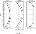
- Figure 4 shows conventional "circular”, “parabolic” and “end stack” lean or sweep stacking axis profiles.
- Such stacking axis profiles drive boundary layer transverse flow towards the midspan, as shown schematically by the arrows superimposed on the profiles of Figure 4 .
- This flow is driven towards the middle over the whole span.
- the magnitude of the transverse flow is proportional to the gradient of the stacking profile.
- the present invention provides an aerofoil member for a compressor of a gas turbine engine, in use the aerofoil member extending between radially inner and radially outer endwalls which define a gas annulus of the compressor; wherein the aerofoil member has a leading edge, a trailing edge, a pressure surface and a suction surface such that successive cross-sections through the aerofoil member transverse to the radial direction provide respective aerofoil sections, and wherein the external shape of the aerofoil member is defined by the stacking of the aerofoil sections on a stacking axis which passes through a reference point common to each aerofoil section; wherein the aerofoil member has lean produced by the projection of the stacking axis onto a plane normal to the engine axis intersecting a first one of the endwalls at an angle of from 5° to 25° to the circumferential direction such that the pressure surface faces the first endwall; and wherein with increasing distance along the stacking axis
- a turning point is meant a local maximum or minimum in a quantity.
- the gradient of the quantity is zero. From a position at the turning point, the quantity either increases in both directions (for a local minimum) or decreases in both directions (for a local maximum).
- the decoupling of midspan and endwall regions of flow can be improved. It is also possible to take better advantage of an endwall region stabilising against corner separation to redistribute low momentum transverse flow across a surface of the member. For example, it is possible to tailor the quantity of transverse flow at each location on the span.
- the stacking axis is confined to a single plane normal to the engine axis, then the projection of the stacking axis onto the normal plane is simply the locus of the stacking axis. However, more generally the stacking axis may not be confined to a single plane normal to the engine axis, such that the stacking axis produces sweep as well as lean.
- the present invention provides a compressor of a gas turbine engine having a circumferential row of aerofoil members according to any one of the previous claims, the aerofoil members extending between radially inner and radially outer endwalls which define a gas annulus of the compressor.
- the present invention provides a gas turbine engine having the compressor of the second aspect.
- the aerofoil member can be a rotor blade or a stator vane.
- the common reference point may be, for example, the leading edge, the trailing edge or the centroid of each aerofoil section.
- the projection of the stacking axis may intersect the first endwall at an angle of from 10° to 20° to the circumferential direction.
- the turning point may be at a radial distance of more than 0.05R, and preferably of more than 0.1R, from the first endwall, where R is the radial distance between the endwalls.
- the turning point may be at a radial distance of less than 0.3R, and preferably of less than 0.2R, from the first endwall, where R is the radial distance between the endwalls.
- the aerofoil member may have further lean produced by the projection of the stacking axis intersecting the second one of the endwalls at an angle of from 5° to 25° to the circumferential direction such that the pressure surface faces the second endwall. With increasing distance along the stacking axis from the second endwall, the stacking axis may then experience a further turning point such that the pressure surface has a convex shape adjacent the second endwall.
- the aerofoil member has the first and the further (i.e. second) turning point, this produces a third turning point in the stacking axis between the first and second turning points, the third turning point being of the opposite sense to the first and second turning points.
- the projection of the stacking axis may intersect the second endwall at an angle of from 10° to 20° to the circumferential direction.
- the further turning point may be at a radial distance of more than 0.05R, and preferably of more than 0.1R, from the second endwall, where R is the radial distance between the endwalls.
- the further turning point may be at a radial distance of less than 0.3R, and preferably of less than 0.2R, from the second endwall, where R is the radial distance between the endwalls.
- a ducted fan gas turbine engine is generally indicated at 10 and has a principal and rotational axis X-X.
- the engine comprises, in axial flow series, an air intake 11, a propulsive fan 12, an intermediate pressure compressor 13, a high-pressure compressor 14, combustion equipment 15, a high-pressure turbine 16, an intermediate pressure turbine 17, a low-pressure turbine 18 and a core engine exhaust nozzle 19.
- a nacelle 21 generally surrounds the engine 10 and defines the intake 11, a bypass duct 22 and a bypass exhaust nozzle 23.
- air entering the intake 11 is accelerated by the fan 12 to produce two air flows: a first air flow A into the intermediate-pressure compressor 13 and a second air flow B which passes through the bypass duct 22 to provide propulsive thrust.
- the intermediate-pressure compressor 13 compresses the air flow A directed into it before delivering that air to the high-pressure compressor 14 where further compression takes place.
- the compressed air exhausted from the high-pressure compressor 14 is directed into the combustion equipment 15 where it is mixed with fuel and the mixture combusted.
- the resultant hot combustion products then expand through, and thereby drive the high, intermediate and low-pressure turbines 16, 17, 18 before being exhausted through the nozzle 19 to provide additional propulsive thrust.
- the high, intermediate and low-pressure turbines respectively drive the high and intermediate-pressure compressors 14, 13 and the fan 12 by suitable interconnecting shafts.
- gas turbine engines to which the present disclosure may be applied may have alternative configurations.
- such engines may have an alternative number of interconnecting shafts (e.g. two) and/or an alternative number of compressors and/or turbines.
- the engine may comprise a gearbox provided in the drive train from a turbine to a compressor and/or fan.
- the intermediate pressure compressor 13 and the high-pressure compressor 14 provide a series of compressor stages, each made up of a circumferential row of rotor blades and an adjacent circumferential row of stator vanes. These blades and vanes are aerofoil members which can benefit from an "inflectional" stacking axis profile, i.e.
- each blade or vane of any given row has a stacking axis
- the projection of which onto a plane normal to the engine axis intersects at least one of the radially inner and radially outer endwalls of the compressor at an angle of from 5° to 25° (preferably from 10° to 20°) to the circumferential direction such that its pressure surface faces that endwall, and the projection of which, with increasing distance along the stacking axis from that endwall, experiences a turning point such that its pressure surface has a convex shape adjacent the endwall.
- Figure 6 shows an inflectional stacking axis profile of this kind in which there is a turning point and convex shape at both endwalls, the profile being the projection of the stacking axis onto a plane normal to the engine axis.
- the arrows superimposed on the profile show the directions of boundary layer transverse flow driven by the profile.
- the inflectional stacking axis profile can be used on rotor blades and/or stator vanes. Additionally or alternatively, it can be used in a shrouded or unshrouded configuration. It does not need to be symmetric, but can be applied to aerofoil members at just one end, which can be an end with a blade tip gap or a fixed end.
- the midspan offset can then be to the opposite side of the line (dashed in Figure 6 ) connecting the points of intersection of the stacking axis profile with the endwalls.
- the midspan offset can be to the same side of this line.
- the displacement of the midspan sections can be positive or negative in the circumferential direction depending on the magnitude of the maximum or minimum of the third turning point.
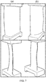
- Figure 7 shows (a) at top a view from the leading edge and at bottom a view from the trailing edge of the suction surface of a shrouded stator vane having a parabolic stacking profile, and (b) at top a view from the leading edge and at bottom a view from the trailing edge of the suction surface of a modified version of the stator vane having an inflectional stacking profile.
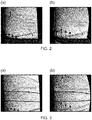
- Figure 8 shows suction surface streamlines at the engine design point for (a) the parabolic vane of Figure 7, and (b) the inflectional vane of Figure 7 .
- the inflectional profile reduces corner and suction surface losses.
- Figure 9 shows suction surface streamlines at a near stall operating condition of the engine for (a) the parabolic vane of Figure 7, and (b) the inflectional vane of Figure 7 .
- the inflectional profile improves corner and suction surface stability.
- Figure 10 shows the radial distribution of loss coefficient for two shrouded stator vanes, one with a conventional parabolic stacking profile and one with the inflectional stacking profile.
- the loss coefficient is calculated from the mixed out values of stagnation pressure at exit from the shrouded stator vane. It can be seen that the inflectional profile maintains the same value of endwall loss as the parabolic stacking profile, but is able to significantly reduce the midspan profile loss. It achieves this benefit by reducing the streamline contraction to zero.
Landscapes
- Engineering & Computer Science (AREA)
- Mechanical Engineering (AREA)
- General Engineering & Computer Science (AREA)
- Physics & Mathematics (AREA)
- Fluid Mechanics (AREA)
- Structures Of Non-Positive Displacement Pumps (AREA)
Applications Claiming Priority (1)
| Application Number | Priority Date | Filing Date | Title |
|---|---|---|---|
| GBGB1707811.4A GB201707811D0 (en) | 2017-05-16 | 2017-05-16 | Compressor aerofoil member |
Publications (2)
| Publication Number | Publication Date |
|---|---|
| EP3404212A1 true EP3404212A1 (fr) | 2018-11-21 |
| EP3404212B1 EP3404212B1 (fr) | 2020-03-04 |
Family
ID=59201658
Family Applications (1)
| Application Number | Title | Priority Date | Filing Date |
|---|---|---|---|
| EP18167527.3A Active EP3404212B1 (fr) | 2017-05-16 | 2018-04-16 | Élément de surface portante de compresseur |
Country Status (4)
| Country | Link |
|---|---|
| US (1) | US10697302B2 (fr) |
| EP (1) | EP3404212B1 (fr) |
| CN (1) | CN108869396B (fr) |
| GB (1) | GB201707811D0 (fr) |
Families Citing this family (1)
| Publication number | Priority date | Publication date | Assignee | Title |
|---|---|---|---|---|
| US11873735B1 (en) | 2022-11-10 | 2024-01-16 | General Electric Company | Composite component for a gas turbine engine |
Citations (7)
| Publication number | Priority date | Publication date | Assignee | Title |
|---|---|---|---|---|
| US5249922A (en) * | 1990-09-17 | 1993-10-05 | Hitachi, Ltd. | Apparatus of stationary blade for axial flow turbine, and axial flow turbine |
| JPH06212902A (ja) * | 1993-01-20 | 1994-08-02 | Toshiba Corp | タービン動翼 |
| EP1098092A2 (fr) * | 1999-11-05 | 2001-05-09 | General Electric Company | Aube statorique |
| EP1106835A2 (fr) * | 1999-12-06 | 2001-06-13 | General Electric Company | Aube de compresseur |
| EP1939405A2 (fr) * | 2006-12-22 | 2008-07-02 | General Electric Company | Aube statorique de turbine |
| EP2075408A2 (fr) * | 2007-12-28 | 2009-07-01 | Ansaldo Energia S.P.A. | Pale de stator de dernier étage d'une section basse pression de turbine à vapeur |
| WO2015126449A1 (fr) * | 2014-02-19 | 2015-08-27 | United Technologies Corporation | Surface portante de moteur à turbine à gaz |
Family Cites Families (10)
| Publication number | Priority date | Publication date | Assignee | Title |
|---|---|---|---|---|
| US3745629A (en) * | 1972-04-12 | 1973-07-17 | Secr Defence | Method of determining optimal shapes for stator blades |
| US4585395A (en) | 1983-12-12 | 1986-04-29 | General Electric Company | Gas turbine engine blade |
| US6709239B2 (en) | 2001-06-27 | 2004-03-23 | Bharat Heavy Electricals Ltd. | Three dimensional blade |
| FR2853022B1 (fr) * | 2003-03-27 | 2006-07-28 | Snecma Moteurs | Aube de redresseur a double courbure |
| US7726937B2 (en) * | 2006-09-12 | 2010-06-01 | United Technologies Corporation | Turbine engine compressor vanes |
| US7758306B2 (en) | 2006-12-22 | 2010-07-20 | General Electric Company | Turbine assembly for a gas turbine engine and method of manufacturing the same |
| US8702398B2 (en) * | 2011-03-25 | 2014-04-22 | General Electric Company | High camber compressor rotor blade |
| GB201303767D0 (en) | 2013-03-04 | 2013-04-17 | Rolls Royce Plc | Stator Vane Row |
| FR3003598B1 (fr) * | 2013-03-20 | 2018-04-06 | Safran Aircraft Engines | Aube et angle de diedre d'aube |
| WO2015126798A1 (fr) | 2014-02-19 | 2015-08-27 | United Technologies Corporation | Profil aérodynamique de moteur à turbine à gaz |
-
2017
- 2017-05-16 GB GBGB1707811.4A patent/GB201707811D0/en not_active Ceased
-
2018
- 2018-04-16 EP EP18167527.3A patent/EP3404212B1/fr active Active
- 2018-05-14 US US15/978,556 patent/US10697302B2/en active Active
- 2018-05-16 CN CN201810467146.5A patent/CN108869396B/zh active Active
Patent Citations (7)
| Publication number | Priority date | Publication date | Assignee | Title |
|---|---|---|---|---|
| US5249922A (en) * | 1990-09-17 | 1993-10-05 | Hitachi, Ltd. | Apparatus of stationary blade for axial flow turbine, and axial flow turbine |
| JPH06212902A (ja) * | 1993-01-20 | 1994-08-02 | Toshiba Corp | タービン動翼 |
| EP1098092A2 (fr) * | 1999-11-05 | 2001-05-09 | General Electric Company | Aube statorique |
| EP1106835A2 (fr) * | 1999-12-06 | 2001-06-13 | General Electric Company | Aube de compresseur |
| EP1939405A2 (fr) * | 2006-12-22 | 2008-07-02 | General Electric Company | Aube statorique de turbine |
| EP2075408A2 (fr) * | 2007-12-28 | 2009-07-01 | Ansaldo Energia S.P.A. | Pale de stator de dernier étage d'une section basse pression de turbine à vapeur |
| WO2015126449A1 (fr) * | 2014-02-19 | 2015-08-27 | United Technologies Corporation | Surface portante de moteur à turbine à gaz |
Also Published As
| Publication number | Publication date |
|---|---|
| CN108869396B (zh) | 2021-02-26 |
| US20180335044A1 (en) | 2018-11-22 |
| GB201707811D0 (en) | 2017-06-28 |
| EP3404212B1 (fr) | 2020-03-04 |
| US10697302B2 (en) | 2020-06-30 |
| CN108869396A (zh) | 2018-11-23 |
Similar Documents
| Publication | Publication Date | Title |
|---|---|---|
| US9726021B2 (en) | High order shaped curve region for an airfoil | |
| US6283705B1 (en) | Variable vane with winglet | |
| US10711614B2 (en) | Gas turbine engine | |
| US20170184053A1 (en) | Gas turbine engine vane splitter | |
| US9957973B2 (en) | Blade with an S-shaped profile for an axial turbomachine compressor | |
| US11353038B2 (en) | Compressor rotor for supersonic flutter and/or resonant stress mitigation | |
| US20180298912A1 (en) | Compressor blades and/or vanes | |
| CA2926970C (fr) | Stator de turbine a gaz muni d'ailerettes | |
| US20210372288A1 (en) | Compressor stator with leading edge fillet | |
| US20180171819A1 (en) | Variable guide vane device | |
| EP3404212B1 (fr) | Élément de surface portante de compresseur | |
| US10578125B2 (en) | Compressor stator vane with leading edge forward sweep | |
| US11634988B2 (en) | Turbomachine blade having a maximum thickness law with high flutter margin | |
| US11639666B2 (en) | Stator with depressions in gaspath wall adjacent leading edges | |
| RU2794951C2 (ru) | Лопатка газотурбинного двигателя с правилом максимальной толщины с большим запасом прочности при флаттере | |
| US20230073422A1 (en) | Stator with depressions in gaspath wall adjacent trailing edges | |
| RU2792505C2 (ru) | Лопатка газотурбинного двигателя, выполненная по правилу прогиба профиля пера, с большим запасом по флаттеру | |
| US11753943B2 (en) | Turbomachine blade having a sweep law with high flutter margin | |
| US10495095B2 (en) | Multistage compressor with aerofoil portion profiled in a spanwise direction |
Legal Events
| Date | Code | Title | Description |
|---|---|---|---|
| PUAI | Public reference made under article 153(3) epc to a published international application that has entered the european phase |
Free format text: ORIGINAL CODE: 0009012 |
|
| STAA | Information on the status of an ep patent application or granted ep patent |
Free format text: STATUS: THE APPLICATION HAS BEEN PUBLISHED |
|
| AK | Designated contracting states |
Kind code of ref document: A1 Designated state(s): AL AT BE BG CH CY CZ DE DK EE ES FI FR GB GR HR HU IE IS IT LI LT LU LV MC MK MT NL NO PL PT RO RS SE SI SK SM TR |
|
| AX | Request for extension of the european patent |
Extension state: BA ME |
|
| STAA | Information on the status of an ep patent application or granted ep patent |
Free format text: STATUS: REQUEST FOR EXAMINATION WAS MADE |
|
| 17P | Request for examination filed |
Effective date: 20190520 |
|
| RBV | Designated contracting states (corrected) |
Designated state(s): AL AT BE BG CH CY CZ DE DK EE ES FI FR GB GR HR HU IE IS IT LI LT LU LV MC MK MT NL NO PL PT RO RS SE SI SK SM TR |
|
| GRAP | Despatch of communication of intention to grant a patent |
Free format text: ORIGINAL CODE: EPIDOSNIGR1 |
|
| STAA | Information on the status of an ep patent application or granted ep patent |
Free format text: STATUS: GRANT OF PATENT IS INTENDED |
|
| INTG | Intention to grant announced |
Effective date: 20200103 |
|
| GRAS | Grant fee paid |
Free format text: ORIGINAL CODE: EPIDOSNIGR3 |
|
| GRAA | (expected) grant |
Free format text: ORIGINAL CODE: 0009210 |
|
| STAA | Information on the status of an ep patent application or granted ep patent |
Free format text: STATUS: THE PATENT HAS BEEN GRANTED |
|
| RAP1 | Party data changed (applicant data changed or rights of an application transferred) |
Owner name: ROLLS-ROYCE PLC |
|
| AK | Designated contracting states |
Kind code of ref document: B1 Designated state(s): AL AT BE BG CH CY CZ DE DK EE ES FI FR GB GR HR HU IE IS IT LI LT LU LV MC MK MT NL NO PL PT RO RS SE SI SK SM TR |
|
| REG | Reference to a national code |
Ref country code: GB Ref legal event code: FG4D |
|
| REG | Reference to a national code |
Ref country code: CH Ref legal event code: EP |
|
| REG | Reference to a national code |
Ref country code: AT Ref legal event code: REF Ref document number: 1240573 Country of ref document: AT Kind code of ref document: T Effective date: 20200315 |
|
| REG | Reference to a national code |
Ref country code: DE Ref legal event code: R096 Ref document number: 602018002789 Country of ref document: DE |
|
| REG | Reference to a national code |
Ref country code: IE Ref legal event code: FG4D |
|
| PG25 | Lapsed in a contracting state [announced via postgrant information from national office to epo] |
Ref country code: RS Free format text: LAPSE BECAUSE OF FAILURE TO SUBMIT A TRANSLATION OF THE DESCRIPTION OR TO PAY THE FEE WITHIN THE PRESCRIBED TIME-LIMIT Effective date: 20200304 Ref country code: FI Free format text: LAPSE BECAUSE OF FAILURE TO SUBMIT A TRANSLATION OF THE DESCRIPTION OR TO PAY THE FEE WITHIN THE PRESCRIBED TIME-LIMIT Effective date: 20200304 Ref country code: NO Free format text: LAPSE BECAUSE OF FAILURE TO SUBMIT A TRANSLATION OF THE DESCRIPTION OR TO PAY THE FEE WITHIN THE PRESCRIBED TIME-LIMIT Effective date: 20200604 |
|
| REG | Reference to a national code |
Ref country code: NL Ref legal event code: MP Effective date: 20200304 |
|
| PG25 | Lapsed in a contracting state [announced via postgrant information from national office to epo] |
Ref country code: LV Free format text: LAPSE BECAUSE OF FAILURE TO SUBMIT A TRANSLATION OF THE DESCRIPTION OR TO PAY THE FEE WITHIN THE PRESCRIBED TIME-LIMIT Effective date: 20200304 Ref country code: SE Free format text: LAPSE BECAUSE OF FAILURE TO SUBMIT A TRANSLATION OF THE DESCRIPTION OR TO PAY THE FEE WITHIN THE PRESCRIBED TIME-LIMIT Effective date: 20200304 Ref country code: BG Free format text: LAPSE BECAUSE OF FAILURE TO SUBMIT A TRANSLATION OF THE DESCRIPTION OR TO PAY THE FEE WITHIN THE PRESCRIBED TIME-LIMIT Effective date: 20200604 Ref country code: GR Free format text: LAPSE BECAUSE OF FAILURE TO SUBMIT A TRANSLATION OF THE DESCRIPTION OR TO PAY THE FEE WITHIN THE PRESCRIBED TIME-LIMIT Effective date: 20200605 Ref country code: HR Free format text: LAPSE BECAUSE OF FAILURE TO SUBMIT A TRANSLATION OF THE DESCRIPTION OR TO PAY THE FEE WITHIN THE PRESCRIBED TIME-LIMIT Effective date: 20200304 |
|
| REG | Reference to a national code |
Ref country code: LT Ref legal event code: MG4D |
|
| PG25 | Lapsed in a contracting state [announced via postgrant information from national office to epo] |
Ref country code: NL Free format text: LAPSE BECAUSE OF FAILURE TO SUBMIT A TRANSLATION OF THE DESCRIPTION OR TO PAY THE FEE WITHIN THE PRESCRIBED TIME-LIMIT Effective date: 20200304 |
|
| PG25 | Lapsed in a contracting state [announced via postgrant information from national office to epo] |
Ref country code: SK Free format text: LAPSE BECAUSE OF FAILURE TO SUBMIT A TRANSLATION OF THE DESCRIPTION OR TO PAY THE FEE WITHIN THE PRESCRIBED TIME-LIMIT Effective date: 20200304 Ref country code: RO Free format text: LAPSE BECAUSE OF FAILURE TO SUBMIT A TRANSLATION OF THE DESCRIPTION OR TO PAY THE FEE WITHIN THE PRESCRIBED TIME-LIMIT Effective date: 20200304 Ref country code: IS Free format text: LAPSE BECAUSE OF FAILURE TO SUBMIT A TRANSLATION OF THE DESCRIPTION OR TO PAY THE FEE WITHIN THE PRESCRIBED TIME-LIMIT Effective date: 20200704 Ref country code: EE Free format text: LAPSE BECAUSE OF FAILURE TO SUBMIT A TRANSLATION OF THE DESCRIPTION OR TO PAY THE FEE WITHIN THE PRESCRIBED TIME-LIMIT Effective date: 20200304 Ref country code: SM Free format text: LAPSE BECAUSE OF FAILURE TO SUBMIT A TRANSLATION OF THE DESCRIPTION OR TO PAY THE FEE WITHIN THE PRESCRIBED TIME-LIMIT Effective date: 20200304 Ref country code: PT Free format text: LAPSE BECAUSE OF FAILURE TO SUBMIT A TRANSLATION OF THE DESCRIPTION OR TO PAY THE FEE WITHIN THE PRESCRIBED TIME-LIMIT Effective date: 20200729 Ref country code: LT Free format text: LAPSE BECAUSE OF FAILURE TO SUBMIT A TRANSLATION OF THE DESCRIPTION OR TO PAY THE FEE WITHIN THE PRESCRIBED TIME-LIMIT Effective date: 20200304 Ref country code: CZ Free format text: LAPSE BECAUSE OF FAILURE TO SUBMIT A TRANSLATION OF THE DESCRIPTION OR TO PAY THE FEE WITHIN THE PRESCRIBED TIME-LIMIT Effective date: 20200304 Ref country code: ES Free format text: LAPSE BECAUSE OF FAILURE TO SUBMIT A TRANSLATION OF THE DESCRIPTION OR TO PAY THE FEE WITHIN THE PRESCRIBED TIME-LIMIT Effective date: 20200304 |
|
| REG | Reference to a national code |
Ref country code: AT Ref legal event code: MK05 Ref document number: 1240573 Country of ref document: AT Kind code of ref document: T Effective date: 20200304 |
|
| REG | Reference to a national code |
Ref country code: DE Ref legal event code: R097 Ref document number: 602018002789 Country of ref document: DE |
|
| PG25 | Lapsed in a contracting state [announced via postgrant information from national office to epo] |
Ref country code: MC Free format text: LAPSE BECAUSE OF FAILURE TO SUBMIT A TRANSLATION OF THE DESCRIPTION OR TO PAY THE FEE WITHIN THE PRESCRIBED TIME-LIMIT Effective date: 20200304 |
|
| PLBE | No opposition filed within time limit |
Free format text: ORIGINAL CODE: 0009261 |
|
| STAA | Information on the status of an ep patent application or granted ep patent |
Free format text: STATUS: NO OPPOSITION FILED WITHIN TIME LIMIT |
|
| PG25 | Lapsed in a contracting state [announced via postgrant information from national office to epo] |
Ref country code: AT Free format text: LAPSE BECAUSE OF FAILURE TO SUBMIT A TRANSLATION OF THE DESCRIPTION OR TO PAY THE FEE WITHIN THE PRESCRIBED TIME-LIMIT Effective date: 20200304 Ref country code: DK Free format text: LAPSE BECAUSE OF FAILURE TO SUBMIT A TRANSLATION OF THE DESCRIPTION OR TO PAY THE FEE WITHIN THE PRESCRIBED TIME-LIMIT Effective date: 20200304 Ref country code: IT Free format text: LAPSE BECAUSE OF FAILURE TO SUBMIT A TRANSLATION OF THE DESCRIPTION OR TO PAY THE FEE WITHIN THE PRESCRIBED TIME-LIMIT Effective date: 20200304 Ref country code: LU Free format text: LAPSE BECAUSE OF NON-PAYMENT OF DUE FEES Effective date: 20200416 |
|
| REG | Reference to a national code |
Ref country code: BE Ref legal event code: MM Effective date: 20200430 |
|
| 26N | No opposition filed |
Effective date: 20201207 |
|
| PG25 | Lapsed in a contracting state [announced via postgrant information from national office to epo] |
Ref country code: SI Free format text: LAPSE BECAUSE OF FAILURE TO SUBMIT A TRANSLATION OF THE DESCRIPTION OR TO PAY THE FEE WITHIN THE PRESCRIBED TIME-LIMIT Effective date: 20200304 Ref country code: PL Free format text: LAPSE BECAUSE OF FAILURE TO SUBMIT A TRANSLATION OF THE DESCRIPTION OR TO PAY THE FEE WITHIN THE PRESCRIBED TIME-LIMIT Effective date: 20200304 Ref country code: BE Free format text: LAPSE BECAUSE OF NON-PAYMENT OF DUE FEES Effective date: 20200430 |
|
| PG25 | Lapsed in a contracting state [announced via postgrant information from national office to epo] |
Ref country code: IE Free format text: LAPSE BECAUSE OF NON-PAYMENT OF DUE FEES Effective date: 20200416 |
|
| PG25 | Lapsed in a contracting state [announced via postgrant information from national office to epo] |
Ref country code: CH Free format text: LAPSE BECAUSE OF NON-PAYMENT OF DUE FEES Effective date: 20210430 Ref country code: LI Free format text: LAPSE BECAUSE OF NON-PAYMENT OF DUE FEES Effective date: 20210430 |
|
| PG25 | Lapsed in a contracting state [announced via postgrant information from national office to epo] |
Ref country code: TR Free format text: LAPSE BECAUSE OF FAILURE TO SUBMIT A TRANSLATION OF THE DESCRIPTION OR TO PAY THE FEE WITHIN THE PRESCRIBED TIME-LIMIT Effective date: 20200304 Ref country code: MT Free format text: LAPSE BECAUSE OF FAILURE TO SUBMIT A TRANSLATION OF THE DESCRIPTION OR TO PAY THE FEE WITHIN THE PRESCRIBED TIME-LIMIT Effective date: 20200304 Ref country code: CY Free format text: LAPSE BECAUSE OF FAILURE TO SUBMIT A TRANSLATION OF THE DESCRIPTION OR TO PAY THE FEE WITHIN THE PRESCRIBED TIME-LIMIT Effective date: 20200304 |
|
| PG25 | Lapsed in a contracting state [announced via postgrant information from national office to epo] |
Ref country code: MK Free format text: LAPSE BECAUSE OF FAILURE TO SUBMIT A TRANSLATION OF THE DESCRIPTION OR TO PAY THE FEE WITHIN THE PRESCRIBED TIME-LIMIT Effective date: 20200304 Ref country code: AL Free format text: LAPSE BECAUSE OF FAILURE TO SUBMIT A TRANSLATION OF THE DESCRIPTION OR TO PAY THE FEE WITHIN THE PRESCRIBED TIME-LIMIT Effective date: 20200304 |
|
| P01 | Opt-out of the competence of the unified patent court (upc) registered |
Effective date: 20230528 |
|
| PGFP | Annual fee paid to national office [announced via postgrant information from national office to epo] |
Ref country code: GB Payment date: 20240423 Year of fee payment: 7 |
|
| PGFP | Annual fee paid to national office [announced via postgrant information from national office to epo] |
Ref country code: DE Payment date: 20240429 Year of fee payment: 7 |
|
| PGFP | Annual fee paid to national office [announced via postgrant information from national office to epo] |
Ref country code: FR Payment date: 20240430 Year of fee payment: 7 |