EP3404203B2 - Bohrlochfutter - Google Patents
Bohrlochfutter Download PDFInfo
- Publication number
- EP3404203B2 EP3404203B2 EP18156530.0A EP18156530A EP3404203B2 EP 3404203 B2 EP3404203 B2 EP 3404203B2 EP 18156530 A EP18156530 A EP 18156530A EP 3404203 B2 EP3404203 B2 EP 3404203B2
- Authority
- EP
- European Patent Office
- Prior art keywords
- tracer
- liner
- inner tube
- well
- outer tube
- Prior art date
- Legal status (The legal status is an assumption and is not a legal conclusion. Google has not performed a legal analysis and makes no representation as to the accuracy of the status listed.)
- Active
Links
Images
Classifications
-
- E—FIXED CONSTRUCTIONS
- E21—EARTH OR ROCK DRILLING; MINING
- E21B—EARTH OR ROCK DRILLING; OBTAINING OIL, GAS, WATER, SOLUBLE OR MELTABLE MATERIALS OR A SLURRY OF MINERALS FROM WELLS
- E21B17/00—Drilling rods or pipes; Flexible drill strings; Kellies; Drill collars; Sucker rods; Cables; Casings; Tubings
-
- E—FIXED CONSTRUCTIONS
- E21—EARTH OR ROCK DRILLING; MINING
- E21B—EARTH OR ROCK DRILLING; OBTAINING OIL, GAS, WATER, SOLUBLE OR MELTABLE MATERIALS OR A SLURRY OF MINERALS FROM WELLS
- E21B43/00—Methods or apparatus for obtaining oil, gas, water, soluble or meltable materials or a slurry of minerals from wells
- E21B43/02—Subsoil filtering
- E21B43/10—Setting of casings, screens, liners or the like in wells
-
- E—FIXED CONSTRUCTIONS
- E21—EARTH OR ROCK DRILLING; MINING
- E21B—EARTH OR ROCK DRILLING; OBTAINING OIL, GAS, WATER, SOLUBLE OR MELTABLE MATERIALS OR A SLURRY OF MINERALS FROM WELLS
- E21B43/00—Methods or apparatus for obtaining oil, gas, water, soluble or meltable materials or a slurry of minerals from wells
- E21B43/11—Perforators; Permeators
- E21B43/116—Gun or shaped-charge perforators
-
- E—FIXED CONSTRUCTIONS
- E21—EARTH OR ROCK DRILLING; MINING
- E21B—EARTH OR ROCK DRILLING; OBTAINING OIL, GAS, WATER, SOLUBLE OR MELTABLE MATERIALS OR A SLURRY OF MINERALS FROM WELLS
- E21B47/00—Survey of boreholes or wells
- E21B47/10—Locating fluid leaks, intrusions or movements
- E21B47/11—Locating fluid leaks, intrusions or movements using tracers; using radioactivity
Definitions
- the present invention concerns a liner for a well having a tracer system incorporated therein.
- a liner or casing i.e. a pipe
- the liner has various functions, including protecting the borehole from unstable rock formations and protecting the rock formations from production chemicals and produced fluids flowing in the borehole. It also provides a regular and stable path for the insertion of tools required for the operation of the well.
- the liner or casing is usually formed from sections of metal pipe assembled and installed during completion of the well.
- Well liners are cemented in place by filling the gap between the sides of the borehole and the external wall of the liner with cement.
- a well bore is drilled using a drill bit though the target reservoir zone.
- the drill is pulled and tubing forming the liner or casing is run that is smaller than the well bore through the drilled area.
- a batch of cement is pumped into the inner tubing with a small movable plug at the top. It is then pushed with fluid with cement flowing to the very end of the tubing and then forced between the well bore and outer wall of the tubing.
- the cement plug is pushed to the end of the tubing and stopped.
- the plug acts as a barrier between cement and "push” fluid and in being pushed down the borehole “wipes" the inner walls of the tubing as it goes.
- European Patent Number 1991759 describes a method of monitoring the flow of fluid within or from a reservoir comprising the steps of inserting a solid non-radioactive tracer into the reservoir by means of a perforation tool, thereafter collecting a sample of fluid within or flowing from the reservoir and analysing said sample to determine the amount of said tracer contained in the sample. From the presence or absence of tracer in the sample, its amount and other parameters such as timing of the sample collection etc, information about the fluid flow within the reservoir may be gathered.
- US 3,623,842 describes a method of determining fluid saturations in reservoirs by injecting at least two tracers having different partition coefficients between fluid phases (e.g. oil and water) into the formation and monitoring the appearance of the two tracers in the produced fluids.
- Radioactive tracers have been widely used for many years in well-monitoring applications. As an example, see US 5,077,471 , in which radioactive tracers are injected into a perforated well-bore, sealed and then monitored for decay to indicate the fluid flow from the formation.
- US 4,755,469 describes the use of rare metal tracers for tracing oil and associated reservoir fluids by mixing an oil-dispersible rare metal salt with oil or an oil-like composition, injecting the dissolved tracer composition into a subterranean reservoir and analysing oil fluids produced from a different part of the reservoir for the presence of the rare metal to determine whether the oil mixed with the tracer has been produced from the reservoir.
- US 6645769 describes placing different tracers at different parts of the well by adhering polymeric tracers to parts of the completion apparatus so that the tracers may be carried with a fluid as it flows to the well-head.
- WO2004/097155 discloses a casing with an isolated annular space, which can be used for transport of different medias down it the well. Those can be vacuum, air, gas, acids, solids, tracers, or other well stimulating medias.
- WO2011/005988 discloses a downhole screen assembly for dispensing a tracer material.
- US7334486 discloses a device and method for measuring fluid fluxes, solute fluxes and fracture parameters in fracture flow systems.
- tracers with liner tubing before it is installed in the well because incorporation of the tracer could then be carried out under controlled conditions away from the well drilling operation in order that accurate placement within the wellbore could be achieved.
- Well tubing with tracer provision has been described in US 6672385 in which a combined prefabricated liner and matrix system with defined properties for fast and simple well and/or reservoir completion, monitoring and control is provided.
- An embodiment of the combined prefabricated liner and matrix system comprises an outer perforated tubular pipe/pipe system, an inner tubular screen, and a matrix.
- WO2011/153636 describes a wellbore screen including: an apertured base pipe; an intermediate filtering layer including a plurality of metal fibers wrapped helically around the apertured base pipe and a fluid tracing filament wrapped helically about the apertured base pipe, the fluid tracing filament including a filament structure and a tracer carried by the filament structure, the tracer being entrainable in produced fluids in a wellbore environment; and an outer apertured shell over the intermediate layer.
- a problem with these tracer/liner systems is that in the process of cementing the liner in place in which cement is pushed along the inner bore and up the outer wall of the liner, the apertures, which are intended to allow fluid flow, would become blocked with cement, thereby preventing contact of the tracer and well fluids and possibly also reducing the fluid flow as the apertures become blocked. Furthermore, it is not practical to place tracer material within the bore of the liner because the material may interfere with the flow of the cement or the cement plug and may also be disturbed or removed by the cementing operation. It is an object of the present invention to provide a liner with a tracer system that is cementable and overcomes some of the problems of the prior art.
- a method of tracing flow from a subterranean well comprising a well bore penetrating a fluid-bearing rock formation, comprising the steps of:
- the tracer-liner portion for use in a method as defined above.
- the tracer-liner portion comprises an inner tube and an outer tube, each comprising at least one wall having an internal surface and an external surface, and a tracer material, said inner tube being arranged coaxially within said outer tube such that at least a portion of the external surface of said inner tube is covered by said outer tube, and said tracer material is arranged between the internal surface of said outer tube and the external surface of said inner tube, wherein the walls of the inner tube and the outer tube are impermeable to fluid flow.
- the invention is characterized in that the tracer material does not fill the space between the inner and outer tube, the tracer material comprising a tracer compound and a solid matrix material in the form of a solid tracer material which is fixed to the outer surface of the inner tube with an annular gap between the outer tube and the solid tracer material.
- the walls of the inner tube and the outer tube are impermeable to fluid flow during fabrication and installation of the liner. They are not provided with perforations or apertures in contrast to prior art systems.
- This has the advantage that there is no fluid flow system to become blocked during a cementing operation and that the tracer-liner portion of the invention is suitable for use in forming a cemented liner for a well-bore.
- perforations may be formed in the inner and/or the outer tubes so that fluid flowing within or over the liner may contact the tracer material located between the inner and outer tubes. This is conveniently achieved using a perforation tool.
- a perforation tool carrying explosive charges may be inserted into the inner tube of the liner portion and its explosive charges detonated to perforate the liner and the surrounding rock formation. Thereafter, fluid flowing along the liner, or through the liner from the adjacent rock formation, may contact the tracer material through the perforations thus formed and the tracer material may thereby be incorporated into the fluid flow, to be detected downstream of the tracer-liner portion.
- a well liner according to the invention comprises a plurality of liner portions, each joined at at least one end to an adjacent liner portion, at least one of said liner portions comprising a tracer-liner portion of the invention.
- a well-liner according to the invention may comprise more than one tracer-liner portion of the invention, but usually a well-liner comprises at least some other types of liner portion, for example formed from tubing which has no associated tracer materials.
- the tracer-liner portion includes means for joining it to an adjacent liner portion at each end.
- Well-liners formed from liner portions are conventional in the art and the joining means of the tracer-liner portion may comprise any such means which is already known or which may be developed for joining portions of well liner together.
- Such means preferably comprises threaded portions at each end of the liner portion which cooperate with a threaded portion of an adjacent liner portion.
- the well liner portion may be provided with an internally threaded portion at one end and an externally threaded portion at the other end.
- the joining means provide at the end(s) of the tracer-liner portion very preferably is selected to be of a similar type to and to cooperate with the joining means for the liner portions to which it is intended to be joined to assemble the well-liner of which it will form a part.
- the inner tube is preferably formed from metal, especially steel.
- the inner tube is conveniently selected to be of a similar type to the tubing conventionally used for lining or casing a well.
- the inner tube of the tracer-liner portion is preferably selected to be of the same inner diameter and material as other parts of the liner, particularly liner portions which are adjacent to the tracer-liner portions of the invention, in order that the passage of tools and fluids through the liner is uninterrupted. Therefore the inner tube is preferably selected from standard base liner stock which is available for use in the oil and gas industry.
- the outer tube is also preferably formed from metal. The length of the inner tube is not critical and may be varied to suit the application.
- the inner tube may be convenient to form from a length of tubing which is a standard length or of a similar length to the other liner portions used to form the well-liner.
- the inner tube may be longer or, more usually, shorter than the length of adjacent liner portions.
- the outer tube has an internal diameter which is larger than the outer diameter of the inner tube.
- the internal diameter of the outer tube exceeds the outer diameter of the inner tube by an amount sufficient to form a space in which the tracer material is located.
- both inner and outer tubes are circular, the space between them forms an annulus.
- the tracer material does not fill the space between the inner and outer tubes. In this configuration fluid can flow within the space, thereby increasing the contact time between the fluid and the tracer material compared with embodiments in which the space is filled with tracer material.
- the space between the inner and outer tubes is sealed at each end of the outer tube.
- the space may, optionally, be divided along its length if required.
- the tracer-liner portion comprises an inner tube, an outer tube and spacers provided between the external surface of the wall of the inner tube and the outer tube, the dimensions of the spacers defining the space between the inner and outer tubes.
- the spacers are preferably joined to the inner and outer tubes to form a seal.
- the spacers are preferably made of metal and may comprise rings which may be joined to the inner and/or outer tubes by means of welding or other means such as threads or flanges.
- the tracer material comprises a tracer compound and a matrix material.
- the tracer compound may be any compound which can be carried in the flow of fluid through the liner and which is detectable by an appropriate method downstream.
- the range of tracer compounds which may be used is large.
- the type of tracer compound to be used is limited only by its physical form and detectability by a practical method.
- any tracer compound could be used in the tracer-liner portion of the invention, provided it can be placed within the space between the outer and inner tubes.
- the compound is most conveniently a solid compound although liquid compounds may be used if they can be adapted to a form which is handleable and placeable, for example by mixing with or absorption by a solid material.
- the tracer compound may comprise a dye which can be detected by visual means or by a spectroscopic method.
- the dye may be coloured or not coloured to the eye.
- Fluorescent compounds, detectable by fluorescence spectroscopy, are well-known for use as tracers and may be suitable for this application.
- Chemical tracer compounds which are detected by atomic absorption spectroscopy or other methods may be used.
- the tracer compound may be soluble in the fluid flowing in the well or it may be carried in the flow as a particle.
- the tracer compound may be selected to partition into an organic phase or into an aqueous phase such as in the water co-produced in an oil or gas well. The selection of suitable tracer compounds is known in the art and the skilled person is capable of selecting one or more appropriate tracer compounds.
- More than one tracer compound may be used within the same tracer material. For example, different combinations of tracers may be used to identify different tracer-liner portions. When more than one tracer-liner is used within a well or a section of a well, they may contain different tracer compounds or combinations of tracer compounds so that fluid passing through each tracer-liner may be identified.
- the tracer compound is dispersed in a matrix material.
- the combination of tracer compound and matrix material is a solid tracer material.
- the matrix material may be a solid material such as a polymeric material, paint, wax or bituminous material.
- the tracer may be chemically bound to the matrix or may simply be physically dispersed therein.
- the tracer material comprises a matrix
- the tracer is typically released into fluid flowing past the material by dissolution of either the matrix material or the tracer compound in the fluid.
- the matrix may be selected to degrade in a controlled manner on contact with the fluid, for example by hydrolysis of a hydrolytically unstable polymer matrix.
- the dissolution or degradation mechanism may be enhanced by the conditions of temperature and pressure found in the well.
- delayed or controlled release tracer materials is preferred in some embodiments of the tracer-liner of the invention to provide a traceable flow over a longer period. However in some cases it is only required to trace a flow over a short period, for example to determine if a perforation operation has resulted in a successful fluid flow. Therefore the selection of tracer material depends upon the job in which the tracer-liner is to be used. When different tracer materials are used in the same or different tracer-liners within a well, they may be designed to be released at different rates by appropriate selection of one or more matrices or other means to provide delayed or controlled release.
- a tracer-liner of the invention may contain a tracer material which is released rapidly on contact with a fluid and one or more additional tracer materials which are designed to release tracer over a longer period of time.
- fluid contacting the tracer materials in the tracer-liner may be detected at different stages in the production history of the well.
- the tracer compounds in each tracer material may be the same or different. Different tracer materials may be visually coloured or otherwise marked in order to identify them during assembly of the tracer-liner.
- the tracer material comprising a tracer compound and a solid matrix material in the form of a solid tracer material is fixed to the outer surface of the inner pipe or it is fixed to the inner surface of the outer pipe.
- the tracer may extend around the circumference of the inner pipe in a continuous layer or it may alternatively be discontinuous.
- a tracer material dispersed in a settable matrix material may be applied to the outside of the inner tube by printing, painting or coating and then cured or dried in place.
- a tracer compound may be dispersed in a solid matrix to form solid tracer blocks or sheets. Tracer materials in that form may then be attached to the inner or the outer tube surfaces by means of adhesives or by clips or ties.
- tracer in the form of fibres or an elongate tape or sheet may be wrapped around the inner tube.
- the tracer material may be selected or treated to provide a surface which attracts the fluid or a selected portion of the fluid.
- a solid polymeric matrix containing tracer may have a hydrophilic or hydrophobic surface depending on whether the tracer is intended to be released into an organic or aqueous fluid.
- the tracer material is a solid, for example formed as a block or sheet, and it may be provided with surface features such as a textured surface and/or ribs, channels, protrusions and bosses to promote flow over the surface of the tracer.
- the solid tracer blocks or sheets are shaped to fit into the space between the outer and inner tubes and may include particular adaptations to enable them to be fitted into the space.
- the tracer material may take the form of a mat or sheet formed of a polymeric matrix material incorporating a dispersed phase of a tracer compound.
- the sheets or mats are flexible in at least one direction. Sheets of material have two opposing major surfaces separated by the thickness of the sheet and bounded by one or more minor surfaces.
- the sheets of tracer material may include incisions or channels extending from a major surface thereof towards the other major surface.
- the incisions or channels may extend completely through the thickness of the sheet or they may extend only partially through the thickness of the sheet. Incisions or channels may be provided on both major surfaces or only one.
- a sheet of tracer material may incorporate linear channels extending partially through the thickness of the sheet.
- the channels may extend between one edge of the sheet and an opposed edge.
- the channels allow the sheet to be formed around a curved shape such as a pipe or tube so that the external surface of the sheet containing the channels can deform to accommodate an external curve. When the sheet is formed into such a curved shape, the channels open, thereby providing means for fluid flow along the sheet and an increased surface area for the fluid to contact the tracer.
- a tracer material in the form of a sheet or block may include ribs, bosses or other protrusions extending outwardly from one major surface thereof in a direction away from the other major surface, i.e. to protrude from a major surface of the sheet.
- a "rib" in the context of this patent application means a generally elongate protrusion or projection extending outwardly from a surface.
- a rib may, but need not, extend continuously or discontinuously from an edge of a sheet to the same or another edge of a sheet.
- a rib may be of uniform dimension or shape along its length.
- a rib may taper to a smaller dimension at a distance further from the surface of the sheet than its corresponding dimension nearer to the sheet.
- a “boss” or “embossment” is intended to mean a protrusion or projection from a surface of the sheet.
- a boss may, for example take the form of a generally circular, irregular or polyhedral shaped portion of the sheet extending outwardly from a major surface of the sheet. Ribs, bosses or other protrusions may be present on both major surfaces of the sheet.
- a sheet of tracer material may possess at least one channel or incision and also at least one rib, protrusion or boss. Ribs may be straight or curved. Ribs may be parallel to each other.
- the sheet may be flexible.
- the tracer in the form of a solid tracer material may be otherwise adapted to conform to the shape of a space between the internal surface of said outer tube and the external surface of said inner tube.
- the sheet may be fixed into position around the outer surface of the inner tube using cable ties, for example.
- a method of tracing flow from a subterranean well comprising a well bore penetrating a fluid-bearing rock formation comprises the steps of: inserting a well-liner into said well, said well-liner comprising a plurality of liner portions, each joined at at least one end to an adjacent liner portion, wherein at least one of said liner portions comprises a tracer-liner portion according to the invention, the outer wall of said well liner and the inner surface of said well-bore defining a gap; filling said gap with a settable fluid material and thereafter allowing said fluid material to set to form a solid material; forming perforations in the inner and outer tubes and the solid material so that fluid flowing within or over the liner may contact the tracer material located between the inner and outer tubes; collecting a sample of fluid at a location downstream of said perforations; analysing said sample to determine whether said tracer compound is present; and inferring from the presence or absence of said tracer compound in the sample whether fluid has contacted
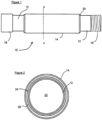
- Figs 1 and 2 show a tracer-liner portion according to the invention 10.
- the tracer-liner portion comprises an inner steel pipe having a 5.5 inch (140 mm) inside diameter 12 and an outer steel pipe 14 having an inside diameter of approx. 6.4 inches (163 mm).
- the pipes are formed from high strength steel of the type specified for well liner fabrication.
- Inner pipe 12 is provided with threaded ends 16 (external thread) and 18 (internal thread). Threaded portions 16 and 18 are capable of engaging with threaded portions of adjacent pipes so that an elongate well-liner may be constructed by joining adjacent pipes together by means of the threaded portions.
- the pipe 12 is very conveniently a standard liner pipe which is provided with standard threaded portions for joining to standard liner pipes used in the industry.
- a cavity is present between the outer and inner pipes, the cavity being bounded at each end by the spacer rings 20.
- Part of the cavity is filled with a slow-release, polymeric tracer material 24.
- the remainder of the cavity forms an annular gap 26, about 0.09 inch (2.5mm) wide, between the outer pipe 14 and the tracer material.
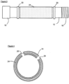
- Fig 3 shows an internal view of the tracer-liner portion of Fig 1 without the outer tube.
- Steel spacer rings 20 are shown in position on the inner pipe 12.
- a layer of tracer material 24 is fixed around the outside of the inner pipe between the spacer rings.
- the outer pipe is then welded to the outer circumference of the rings 20.
- the tracer-liner portion is assembled into a well-liner by joining it to adjacent liner portions which need not be tracer-liner portions.
- the cementing operation is carried out when the assembled liner is in position in a borehole by passing the cement and cement plug into the lumen 22 of the liner and forcing the cement under pressure into the annulus between the walls of a borehole and the outside of the liner.
- the liner may be perforated in a subsequent perforation operation.
- perforation of the inner and outer tubes of the tracer-liner portion forms apertures 28 which allow the ingress of fluids into the gap 26 where the fluids contact the tracer material 24. Release of some tracer material into the fluids as a result of such contact then allows the tracer to be detected down-stream of the tracer-liner portion, which may provide information concerning the source or flow path of the fluid containing the tracer.
Landscapes
- Engineering & Computer Science (AREA)
- Geology (AREA)
- Life Sciences & Earth Sciences (AREA)
- Mining & Mineral Resources (AREA)
- Physics & Mathematics (AREA)
- Environmental & Geological Engineering (AREA)
- Fluid Mechanics (AREA)
- General Life Sciences & Earth Sciences (AREA)
- Geochemistry & Mineralogy (AREA)
- Geophysics (AREA)
- Mechanical Engineering (AREA)
- Geophysics And Detection Of Objects (AREA)
- Rigid Pipes And Flexible Pipes (AREA)
Claims (12)
- Ein Verfahren zum Verfolgen von Strömung aus einem unterirdischen Bohrloch, das eine Bohrlochbohrung beinhaltet, die in eine fluidtragende Gesteinsformation eindringt, beinhaltend die folgenden Schritte:a. Bilden einer Bohrlochauskleidung gemäß einem Verfahren, das den Schritt des Zusammenfügens einer Vielzahl von Auskleidungsabschnitten an deren Enden zum Bilden einer Bohrlochauskleidung beinhaltet, wobei mindestens einer der Auskleidungsabschnitte einen Tracer-Liner-Abschnitt (10) beinhaltet, wobei der Tracer-Auskleidungsabschnitt (10) ein Innenrohr (12) und ein Außenrohr (14) beinhaltet, die jeweils mindestens eine Wand mit einer inneren Fläche und einer äußeren Fläche aufweisen, wobei die Wände des Innenrohrs (12) und des Außenrohrs (14) für einen Fluidstrom undurchlässig sind, wobei das Außenrohr (14) einen inneren Durchmesser aufweist, der größer als der Außendurchmesser des Innenrohrs (12) ist, wobei das Innenrohr (12) koaxial innerhalb des Außenrohrs (14) so angeordnet ist, dass mindestens ein Teil der äußeren Fläche des Innenrohrs (12) von dem Außenrohr (14) bedeckt ist; der innere Durchmesser des Außenrohrs (14) den Außendurchmesser des Innenrohrs (12) um einen Betrag übersteigt, der ausreicht, um einen Raum zwischen der äußeren Fläche des Innenrohrs (12) und der inneren Fläche des Außenrohrs (14) zu bilden, und ein Tracer-Material (24), das eine Tracer-Verbindung enthält, in diesem Raum vorhanden ist, dadurch gekennzeichnet, dass das Tracer-Material (24) diesen Raum nicht ausfüllt, wobei das Tracer-Material (24) eine Tracer-Verbindung und ein festes Matrixmaterial in Form eines festen Tracer-Materials beinhaltet, das an der Außenfläche des Innenrohrs (12) mit einem Ringspalt (26) zwischen dem Außenrohr (14) und dem festen Tracer-Material befestigt ist, und Einsetzen der Bohrlochauskleidung in das Bohrloch, wobei die Außenwand der Bohrlochauskleidung und die Innenfläche des Bohrlochs einen Spalt definieren;b. Füllen des Spaltes mit einem aushärtbaren Fluidmaterial und anschließendes Aushärten des Fluidmaterials, um ein festes Material zu bilden;c. Bilden von Perforationen (28) in dem Innen- und Außenrohr (12; 14) und dem festen Material, sodass das innerhalb der oder über die Auskleidung fließende Fluid mit dem zwischen dem Innen- und Außenrohr (12; 14) angeordneten Tracer-Material (24) in Kontakt kommen kann;d. Sammeln einer Fluidprobe an einer Stelle stromabwärts der Perforationen (28);e. Analysieren der Probe, um zu bestimmen, ob die Tracer-Verbindung vorhanden ist; undf. Ableiten aus dem Vorhandensein oder dem Fehlen der Tracer-Verbindung in der Probe, ob Fluid mit dem Tracer (24) im Bereich der Perforationen (28) in Kontakt gekommen ist.
- Verfahren gemäß Anspruch 1, wobei die Perforationen (28) durch Einführen eines Sprengladungen tragenden Perforationswerkzeugs in das Innenrohr (12) des Auskleidungsabschnitts (10) und Detonieren der Sprengladungen gebildet werden.
- Ein Tracer-Auskleidungsabschnitt (10) zur Verwendung in einem Verfahren gemäß Anspruch 1 oder 2, wobei der Tracer-Verkleidungsabschnitt (10) ein Innenrohr (12) und ein Außenrohr (14) beinhaltet, die jeweils mindestens eine Wand mit einer innere Fläche und einer äußeren Fläche beinhalten, wobei die Wände des Innenrohrs (12) und des Außenrohrs (14) für einen Fluidstrom undurchlässig sind, wobei das Außenrohr (14) einen inneren Durchmesser aufweist, der größer als der Außendurchmesser des Innenrohrs (12) ist, wobei das Innenrohr (12) koaxial innerhalb des Außenrohrs (14) so angeordnet ist, dass mindestens ein Abschnitt der äußeren Fläche des Innenrohrs (12) von dem Außenrohr (14) bedeckt ist; der innere Durchmesser des Außenrohrs (14) den Außendurchmesser des Innenrohrs (12) um einen Betrag übersteigt, der ausreicht, um einen Raum zwischen der äußeren Fläche des Innenrohrs (12) und der inneren Fläche des Außenrohrs (14) zu bilden, und ein Tracer-Material (24), das eine Tracer-Verbindung enthält, in diesem Raum vorhanden ist, dadurch gekennzeichnet, dass das Tracer-Material (24) diesen Raum nicht ausfüllt, wobei das Tracer-Material (24) eine Tracer-Verbindung und ein festes Matrixmaterial in Form eines festen Tracer-Materials beinhaltet, das an der Außenfläche des Innenrohrs (12) mit einem Ringspalt (26) zwischen dem Außenrohr (14) und dem festen Tracer-Material befestigt ist.
- Tracer-Auskleidungsabschnitt (10) gemäß Anspruch 3, der ferner mindestens einen Abstandshalter (20) zwischen der äußeren Fläche der Wand des Innenrohrs (12) und dem Außenrohr (14) aufweist.
- Tracer-Auskleidungsabschnitt (10) gemäß Anspruch 3 oder 4, wobei das Matrixmaterial aus der Gruppe ausgewählt ist, die aus einem Polymermaterial, einer Farbe, einem Wachs oder einem bituminösen Material besteht.
- Tracer-Auskleidungsabschnitt (10) gemäß Anspruch 5, wobei das Tracer-Material (24) eine Tracer-Verbindung aufweist, die in einer festen Polymermatrix in Form eines Blocks oder einer dünnen Schicht dispergiert ist.
- Tracer-Auskleidungsabschnitt (10) gemäß Anspruch 6, wobei der Block oder die dünne Schicht eine texturierte Oberfläche aufweist.
- Tracer-Auskleidungsabschnitt (10) gemäß einem der Ansprüche 6 bis 7, wobei die Oberfläche der festen Polymermatrix mindestens ein topographisches Merkmal aufweist, das aus Rippen, Kanälen und Vorsprüngen ausgewählt ist.
- Tracer-Auskleidungsabschnitt (10) gemäß einem der Ansprüche 3 bis 8, wobei die Tracer-Verbindung so ausgewählt ist, dass sie sich in eine organischen Phase verteilt.
- Tracer-Auskleidungsabschnitt (10) gemäß einem der Ansprüche 3 bis 9, wobei die Tracer-Verbindung so ausgewählt ist, dass sie sich in eine wässrigen Phase verteilt.
- Tracer-Auskleidungsabschnitt (10) gemäß einem der Ansprüche 3 bis 10, wobei mehr als eine Tracer-Verbindung in dem Tracer-Auskleidungsabschnitt (10) vorhanden ist.
- Eine Bohrlochauskleidung, die eine Vielzahl von Auskleidungsabschnitten beinhaltet, von denen jeder an mindestens einem Ende mit einem benachbarten Auskleidungsabschnitt verbunden ist, wobei mindestens einer der Auskleidungsabschnitte einen Tracer-Auskleidungsabschnitt (10) gemäß einem der Ansprüche 3-11 beinhaltet.
Applications Claiming Priority (3)
| Application Number | Priority Date | Filing Date | Title |
|---|---|---|---|
| GBGB1311609.0A GB201311609D0 (en) | 2013-06-28 | 2013-06-28 | Well liner |
| PCT/GB2014/051975 WO2014207483A2 (en) | 2013-06-28 | 2014-06-27 | Well liner |
| EP14735669.5A EP3014064B1 (de) | 2013-06-28 | 2014-06-27 | Verschalungselement |
Related Parent Applications (3)
| Application Number | Title | Priority Date | Filing Date |
|---|---|---|---|
| PCT/GB2014/051975 Previously-Filed-Application WO2014207483A2 (en) | 2013-06-28 | 2014-06-27 | Well liner |
| EP14735669.5A Division-Into EP3014064B1 (de) | 2013-06-28 | 2014-06-27 | Verschalungselement |
| EP14735669.5A Division EP3014064B1 (de) | 2013-06-28 | 2014-06-27 | Verschalungselement |
Publications (4)
| Publication Number | Publication Date |
|---|---|
| EP3404203A2 EP3404203A2 (de) | 2018-11-21 |
| EP3404203A3 EP3404203A3 (de) | 2019-02-13 |
| EP3404203B1 EP3404203B1 (de) | 2021-01-06 |
| EP3404203B2 true EP3404203B2 (de) | 2024-08-21 |
Family
ID=48999200
Family Applications (2)
| Application Number | Title | Priority Date | Filing Date |
|---|---|---|---|
| EP14735669.5A Active EP3014064B1 (de) | 2013-06-28 | 2014-06-27 | Verschalungselement |
| EP18156530.0A Active EP3404203B2 (de) | 2013-06-28 | 2014-06-27 | Bohrlochfutter |
Family Applications Before (1)
| Application Number | Title | Priority Date | Filing Date |
|---|---|---|---|
| EP14735669.5A Active EP3014064B1 (de) | 2013-06-28 | 2014-06-27 | Verschalungselement |
Country Status (6)
| Country | Link |
|---|---|
| US (2) | US9951568B2 (de) |
| EP (2) | EP3014064B1 (de) |
| BR (1) | BR112015032433B1 (de) |
| DK (2) | DK3014064T3 (de) |
| GB (2) | GB201311609D0 (de) |
| WO (1) | WO2014207483A2 (de) |
Families Citing this family (5)
| Publication number | Priority date | Publication date | Assignee | Title |
|---|---|---|---|---|
| FR3022577B1 (fr) * | 2014-06-18 | 2016-07-29 | Saltel Ind | Dispositif de chemisage ou d'obturation d'un puits ou d'une canalisation |
| US10338336B1 (en) * | 2018-01-08 | 2019-07-02 | Weatherford Technology Holdings, Llc | Fiber optic cable for inhibiting breaching fluid flow |
| US11988793B2 (en) * | 2020-09-30 | 2024-05-21 | Saudi Arabian Oil Company | Waterflood front imaging using segmentally insulated well liners as on-demand electrodes |
| CN115614028A (zh) * | 2021-07-13 | 2023-01-17 | 西安思坦油气工程服务有限公司 | 示踪剂找水工具及示踪剂产液剖面找水方法 |
| WO2025181185A1 (en) * | 2024-02-26 | 2025-09-04 | Resman As | Method and system for reservoir inflow quantification |
Citations (4)
| Publication number | Priority date | Publication date | Assignee | Title |
|---|---|---|---|---|
| US5892147A (en) † | 1996-06-28 | 1999-04-06 | Norsk Hydro Asa | Method for the determination of inflow of oil and/or gas into a well |
| WO2011153636A1 (en) † | 2010-06-11 | 2011-12-15 | Absolute Completion Technologies Ltd. | Wellbore screen with tracer for fluid detection |
| WO2012057634A1 (en) † | 2010-10-29 | 2012-05-03 | Resman As | Method for using tracer flowback for estimating influx volumes of fluids from different influx zones |
| WO2012177147A2 (en) † | 2011-06-24 | 2012-12-27 | Resman As | On-site real time detection of tracers |
Family Cites Families (19)
| Publication number | Priority date | Publication date | Assignee | Title |
|---|---|---|---|---|
| US2114521A (en) | 1936-06-08 | 1938-04-19 | Cicero C Brown | Method of completing wells |
| US3623842A (en) | 1969-12-29 | 1971-11-30 | Exxon Research Engineering Co | Method of determining fluid saturations in reservoirs |
| US4755469A (en) | 1982-09-27 | 1988-07-05 | Union Oil Company Of California | Oil tracing method |
| US5077471A (en) | 1990-09-10 | 1991-12-31 | Halliburton Logging Services, Inc. | Method and apparatus for measuring horizontal fluid flow in downhole formations using injected radioactive tracer monitoring |
| DE19731315A1 (de) | 1997-07-16 | 1999-01-21 | Ransmayer A & Rodrian A | Verfahren zur Herstellung speziell strukturierter Oberflächen thermoplastischer Kunststoff-Formkörper und ihre Anwendung |
| US6640605B2 (en) | 1999-01-27 | 2003-11-04 | Milgo Industrial, Inc. | Method of bending sheet metal to form three-dimensional structures |
| NO20002137A (no) | 2000-04-26 | 2001-04-09 | Sinvent As | Reservoarovervåkning ved bruk av kjemisk intelligent frigjøring av tracere |
| EP1277051B1 (de) | 2000-04-26 | 2006-08-23 | ResMan AS | Überwachung eines reservoirs |
| WO2002008562A2 (en) * | 2000-07-21 | 2002-01-31 | Sinvent As | Combined liner and matrix system, use of the system and method for control and monitoring of processes in a well |
| NO318968B1 (no) * | 2002-12-16 | 2005-05-30 | Einar Kristiansen | Foringsror med isolert anulaert hulrom |
| NO321768B1 (no) | 2004-06-30 | 2006-07-03 | Inst Energiteknik | System for tracerfrigjoring i en fluidstrom |
| GB0604451D0 (en) | 2006-03-06 | 2006-04-12 | Johnson Matthey Plc | Tracer method and apparatus |
| US7334486B1 (en) | 2006-04-24 | 2008-02-26 | University Of Florida Research Foundation, Inc. | Device and method for measuring fluid fluxes, solute fluxes and fracture parameters in fracture flow systems |
| US7703538B2 (en) * | 2006-06-23 | 2010-04-27 | Baker Hughes Incorporated | Access apparatus from a tubular into a downhole hydraulic control circuit and associated method |
| EP2045437B1 (de) | 2007-09-06 | 2012-01-25 | Absolute Completion Technologies LTD. | Bohrlochflüssigkeitsbehandlungsrohr und Verfahren |
| US9290689B2 (en) * | 2009-06-03 | 2016-03-22 | Schlumberger Technology Corporation | Use of encapsulated tracers |
| WO2011005988A1 (en) * | 2009-07-10 | 2011-01-13 | Schlumberger Canada Limited | Apparatus and methods for inserting and removing tracer materials in downhole screens |
| US8230731B2 (en) | 2010-03-31 | 2012-07-31 | Schlumberger Technology Corporation | System and method for determining incursion of water in a well |
| US9212540B2 (en) * | 2010-06-11 | 2015-12-15 | Absolute Completion Technologies Ltd. | Wellbore fluid treatment and method |
-
2013
- 2013-06-28 GB GBGB1311609.0A patent/GB201311609D0/en not_active Ceased
-
2014
- 2014-06-27 US US14/901,505 patent/US9951568B2/en active Active
- 2014-06-27 EP EP14735669.5A patent/EP3014064B1/de active Active
- 2014-06-27 GB GB1411521.6A patent/GB2517073B/en active Active
- 2014-06-27 DK DK14735669.5T patent/DK3014064T3/en active
- 2014-06-27 WO PCT/GB2014/051975 patent/WO2014207483A2/en not_active Ceased
- 2014-06-27 EP EP18156530.0A patent/EP3404203B2/de active Active
- 2014-06-27 DK DK18156530.0T patent/DK3404203T4/da active
- 2014-06-27 BR BR112015032433-9A patent/BR112015032433B1/pt active IP Right Grant
-
2018
- 2018-03-16 US US15/923,783 patent/US10718167B2/en active Active
Patent Citations (4)
| Publication number | Priority date | Publication date | Assignee | Title |
|---|---|---|---|---|
| US5892147A (en) † | 1996-06-28 | 1999-04-06 | Norsk Hydro Asa | Method for the determination of inflow of oil and/or gas into a well |
| WO2011153636A1 (en) † | 2010-06-11 | 2011-12-15 | Absolute Completion Technologies Ltd. | Wellbore screen with tracer for fluid detection |
| WO2012057634A1 (en) † | 2010-10-29 | 2012-05-03 | Resman As | Method for using tracer flowback for estimating influx volumes of fluids from different influx zones |
| WO2012177147A2 (en) † | 2011-06-24 | 2012-12-27 | Resman As | On-site real time detection of tracers |
Also Published As
| Publication number | Publication date |
|---|---|
| GB201411521D0 (en) | 2014-08-13 |
| EP3014064B1 (de) | 2018-03-21 |
| BR112015032433A2 (pt) | 2017-07-25 |
| DK3404203T4 (da) | 2024-10-07 |
| BR112015032433B1 (pt) | 2021-11-16 |
| DK3014064T3 (en) | 2018-06-25 |
| US20180209219A1 (en) | 2018-07-26 |
| EP3404203A2 (de) | 2018-11-21 |
| DK3404203T3 (da) | 2021-04-06 |
| EP3404203A3 (de) | 2019-02-13 |
| US20160153246A1 (en) | 2016-06-02 |
| WO2014207483A3 (en) | 2015-09-17 |
| US9951568B2 (en) | 2018-04-24 |
| EP3404203B1 (de) | 2021-01-06 |
| US10718167B2 (en) | 2020-07-21 |
| GB2517073A (en) | 2015-02-11 |
| GB2517073B (en) | 2016-03-09 |
| WO2014207483A2 (en) | 2014-12-31 |
| GB201311609D0 (en) | 2013-08-14 |
| EP3014064A2 (de) | 2016-05-04 |
Similar Documents
| Publication | Publication Date | Title |
|---|---|---|
| US10718167B2 (en) | Well liner | |
| EP0604568B1 (de) | Im bohrloch aktiviertes system zur perforierung der bohrlochwand | |
| US5228518A (en) | Downhole activated process and apparatus for centralizing pipe in a wellbore | |
| US5165478A (en) | Downhole activated process and apparatus for providing cathodic protection for a pipe in a wellbore | |
| CA2273568C (en) | A method of installing a casing in a well and apparatus therefor | |
| EP2198119B1 (de) | Fluidsteuervorrichtung und -verfahren für produktions- und injektionsbohrungen | |
| NO20180999A1 (en) | Tracer patch | |
| US20130019770A1 (en) | Device for perforating a material comprising a tail-locking charge case | |
| CA2975736C (en) | Temporarily impermeable sleeve for running a well component in hole | |
| DK179404B1 (en) | A System And A Method For Determining Inflow Distribution In An Openhole Completed Well | |
| US20170159424A1 (en) | Method and system delivering a tracer to a flow | |
| US20060037752A1 (en) | Rat hole bypass for gravel packing assembly | |
| WO2015040042A1 (en) | Detection of a watered out zone in a segmented completion | |
| WO2014207482A2 (en) | Tracer material |
Legal Events
| Date | Code | Title | Description |
|---|---|---|---|
| PUAI | Public reference made under article 153(3) epc to a published international application that has entered the european phase |
Free format text: ORIGINAL CODE: 0009012 |
|
| STAA | Information on the status of an ep patent application or granted ep patent |
Free format text: STATUS: THE APPLICATION HAS BEEN PUBLISHED |
|
| AC | Divisional application: reference to earlier application |
Ref document number: 3014064 Country of ref document: EP Kind code of ref document: P |
|
| AK | Designated contracting states |
Kind code of ref document: A2 Designated state(s): AL AT BE BG CH CY CZ DE DK EE ES FI FR GB GR HR HU IE IS IT LI LT LU LV MC MK MT NL NO PL PT RO RS SE SI SK SM TR |
|
| PUAL | Search report despatched |
Free format text: ORIGINAL CODE: 0009013 |
|
| AK | Designated contracting states |
Kind code of ref document: A3 Designated state(s): AL AT BE BG CH CY CZ DE DK EE ES FI FR GB GR HR HU IE IS IT LI LT LU LV MC MK MT NL NO PL PT RO RS SE SI SK SM TR |
|
| RIC1 | Information provided on ipc code assigned before grant |
Ipc: E21B 47/10 20120101AFI20190110BHEP |
|
| STAA | Information on the status of an ep patent application or granted ep patent |
Free format text: STATUS: REQUEST FOR EXAMINATION WAS MADE |
|
| 17P | Request for examination filed |
Effective date: 20190708 |
|
| RBV | Designated contracting states (corrected) |
Designated state(s): AL AT BE BG CH CY CZ DE DK EE ES FI FR GB GR HR HU IE IS IT LI LT LU LV MC MK MT NL NO PL PT RO RS SE SI SK SM TR |
|
| STAA | Information on the status of an ep patent application or granted ep patent |
Free format text: STATUS: EXAMINATION IS IN PROGRESS |
|
| 17Q | First examination report despatched |
Effective date: 20200225 |
|
| GRAP | Despatch of communication of intention to grant a patent |
Free format text: ORIGINAL CODE: EPIDOSNIGR1 |
|
| STAA | Information on the status of an ep patent application or granted ep patent |
Free format text: STATUS: GRANT OF PATENT IS INTENDED |
|
| INTG | Intention to grant announced |
Effective date: 20200924 |
|
| GRAS | Grant fee paid |
Free format text: ORIGINAL CODE: EPIDOSNIGR3 |
|
| GRAA | (expected) grant |
Free format text: ORIGINAL CODE: 0009210 |
|
| STAA | Information on the status of an ep patent application or granted ep patent |
Free format text: STATUS: THE PATENT HAS BEEN GRANTED |
|
| AC | Divisional application: reference to earlier application |
Ref document number: 3014064 Country of ref document: EP Kind code of ref document: P |
|
| AK | Designated contracting states |
Kind code of ref document: B1 Designated state(s): AL AT BE BG CH CY CZ DE DK EE ES FI FR GB GR HR HU IE IS IT LI LT LU LV MC MK MT NL NO PL PT RO RS SE SI SK SM TR |
|
| REG | Reference to a national code |
Ref country code: GB Ref legal event code: FG4D |
|
| REG | Reference to a national code |
Ref country code: AT Ref legal event code: REF Ref document number: 1352572 Country of ref document: AT Kind code of ref document: T Effective date: 20210115 Ref country code: CH Ref legal event code: EP |
|
| REG | Reference to a national code |
Ref country code: DE Ref legal event code: R096 Ref document number: 602014074137 Country of ref document: DE |
|
| REG | Reference to a national code |
Ref country code: IE Ref legal event code: FG4D |
|
| REG | Reference to a national code |
Ref country code: NL Ref legal event code: FP |
|
| REG | Reference to a national code |
Ref country code: DK Ref legal event code: T3 Effective date: 20210330 |
|
| REG | Reference to a national code |
Ref country code: NO Ref legal event code: T2 Effective date: 20210106 |
|
| REG | Reference to a national code |
Ref country code: AT Ref legal event code: MK05 Ref document number: 1352572 Country of ref document: AT Kind code of ref document: T Effective date: 20210106 |
|
| REG | Reference to a national code |
Ref country code: LT Ref legal event code: MG9D |
|
| PG25 | Lapsed in a contracting state [announced via postgrant information from national office to epo] |
Ref country code: FI Free format text: LAPSE BECAUSE OF FAILURE TO SUBMIT A TRANSLATION OF THE DESCRIPTION OR TO PAY THE FEE WITHIN THE PRESCRIBED TIME-LIMIT Effective date: 20210106 Ref country code: HR Free format text: LAPSE BECAUSE OF FAILURE TO SUBMIT A TRANSLATION OF THE DESCRIPTION OR TO PAY THE FEE WITHIN THE PRESCRIBED TIME-LIMIT Effective date: 20210106 Ref country code: GR Free format text: LAPSE BECAUSE OF FAILURE TO SUBMIT A TRANSLATION OF THE DESCRIPTION OR TO PAY THE FEE WITHIN THE PRESCRIBED TIME-LIMIT Effective date: 20210407 Ref country code: PT Free format text: LAPSE BECAUSE OF FAILURE TO SUBMIT A TRANSLATION OF THE DESCRIPTION OR TO PAY THE FEE WITHIN THE PRESCRIBED TIME-LIMIT Effective date: 20210506 Ref country code: BG Free format text: LAPSE BECAUSE OF FAILURE TO SUBMIT A TRANSLATION OF THE DESCRIPTION OR TO PAY THE FEE WITHIN THE PRESCRIBED TIME-LIMIT Effective date: 20210406 Ref country code: LT Free format text: LAPSE BECAUSE OF FAILURE TO SUBMIT A TRANSLATION OF THE DESCRIPTION OR TO PAY THE FEE WITHIN THE PRESCRIBED TIME-LIMIT Effective date: 20210106 |
|
| PG25 | Lapsed in a contracting state [announced via postgrant information from national office to epo] |
Ref country code: AT Free format text: LAPSE BECAUSE OF FAILURE TO SUBMIT A TRANSLATION OF THE DESCRIPTION OR TO PAY THE FEE WITHIN THE PRESCRIBED TIME-LIMIT Effective date: 20210106 Ref country code: PL Free format text: LAPSE BECAUSE OF FAILURE TO SUBMIT A TRANSLATION OF THE DESCRIPTION OR TO PAY THE FEE WITHIN THE PRESCRIBED TIME-LIMIT Effective date: 20210106 Ref country code: LV Free format text: LAPSE BECAUSE OF FAILURE TO SUBMIT A TRANSLATION OF THE DESCRIPTION OR TO PAY THE FEE WITHIN THE PRESCRIBED TIME-LIMIT Effective date: 20210106 Ref country code: RS Free format text: LAPSE BECAUSE OF FAILURE TO SUBMIT A TRANSLATION OF THE DESCRIPTION OR TO PAY THE FEE WITHIN THE PRESCRIBED TIME-LIMIT Effective date: 20210106 Ref country code: SE Free format text: LAPSE BECAUSE OF FAILURE TO SUBMIT A TRANSLATION OF THE DESCRIPTION OR TO PAY THE FEE WITHIN THE PRESCRIBED TIME-LIMIT Effective date: 20210106 |
|
| PG25 | Lapsed in a contracting state [announced via postgrant information from national office to epo] |
Ref country code: IS Free format text: LAPSE BECAUSE OF FAILURE TO SUBMIT A TRANSLATION OF THE DESCRIPTION OR TO PAY THE FEE WITHIN THE PRESCRIBED TIME-LIMIT Effective date: 20210506 |
|
| REG | Reference to a national code |
Ref country code: DE Ref legal event code: R026 Ref document number: 602014074137 Country of ref document: DE |
|
| PLBI | Opposition filed |
Free format text: ORIGINAL CODE: 0009260 |
|
| PLAX | Notice of opposition and request to file observation + time limit sent |
Free format text: ORIGINAL CODE: EPIDOSNOBS2 |
|
| PG25 | Lapsed in a contracting state [announced via postgrant information from national office to epo] |
Ref country code: SM Free format text: LAPSE BECAUSE OF FAILURE TO SUBMIT A TRANSLATION OF THE DESCRIPTION OR TO PAY THE FEE WITHIN THE PRESCRIBED TIME-LIMIT Effective date: 20210106 Ref country code: CZ Free format text: LAPSE BECAUSE OF FAILURE TO SUBMIT A TRANSLATION OF THE DESCRIPTION OR TO PAY THE FEE WITHIN THE PRESCRIBED TIME-LIMIT Effective date: 20210106 Ref country code: EE Free format text: LAPSE BECAUSE OF FAILURE TO SUBMIT A TRANSLATION OF THE DESCRIPTION OR TO PAY THE FEE WITHIN THE PRESCRIBED TIME-LIMIT Effective date: 20210106 |
|
| 26 | Opposition filed |
Opponent name: RESMAN AS Effective date: 20211006 |
|
| PG25 | Lapsed in a contracting state [announced via postgrant information from national office to epo] |
Ref country code: RO Free format text: LAPSE BECAUSE OF FAILURE TO SUBMIT A TRANSLATION OF THE DESCRIPTION OR TO PAY THE FEE WITHIN THE PRESCRIBED TIME-LIMIT Effective date: 20210106 Ref country code: SK Free format text: LAPSE BECAUSE OF FAILURE TO SUBMIT A TRANSLATION OF THE DESCRIPTION OR TO PAY THE FEE WITHIN THE PRESCRIBED TIME-LIMIT Effective date: 20210106 |
|
| REG | Reference to a national code |
Ref country code: DE Ref legal event code: R119 Ref document number: 602014074137 Country of ref document: DE |
|
| PG25 | Lapsed in a contracting state [announced via postgrant information from national office to epo] |
Ref country code: MC Free format text: LAPSE BECAUSE OF FAILURE TO SUBMIT A TRANSLATION OF THE DESCRIPTION OR TO PAY THE FEE WITHIN THE PRESCRIBED TIME-LIMIT Effective date: 20210106 Ref country code: AL Free format text: LAPSE BECAUSE OF FAILURE TO SUBMIT A TRANSLATION OF THE DESCRIPTION OR TO PAY THE FEE WITHIN THE PRESCRIBED TIME-LIMIT Effective date: 20210106 Ref country code: ES Free format text: LAPSE BECAUSE OF FAILURE TO SUBMIT A TRANSLATION OF THE DESCRIPTION OR TO PAY THE FEE WITHIN THE PRESCRIBED TIME-LIMIT Effective date: 20210106 |
|
| REG | Reference to a national code |
Ref country code: CH Ref legal event code: PL |
|
| PLBB | Reply of patent proprietor to notice(s) of opposition received |
Free format text: ORIGINAL CODE: EPIDOSNOBS3 |
|
| PG25 | Lapsed in a contracting state [announced via postgrant information from national office to epo] |
Ref country code: SI Free format text: LAPSE BECAUSE OF FAILURE TO SUBMIT A TRANSLATION OF THE DESCRIPTION OR TO PAY THE FEE WITHIN THE PRESCRIBED TIME-LIMIT Effective date: 20210106 |
|
| REG | Reference to a national code |
Ref country code: BE Ref legal event code: MM Effective date: 20210630 |
|
| PG25 | Lapsed in a contracting state [announced via postgrant information from national office to epo] |
Ref country code: LU Free format text: LAPSE BECAUSE OF NON-PAYMENT OF DUE FEES Effective date: 20210627 |
|
| PG25 | Lapsed in a contracting state [announced via postgrant information from national office to epo] |
Ref country code: LI Free format text: LAPSE BECAUSE OF NON-PAYMENT OF DUE FEES Effective date: 20210630 Ref country code: IT Free format text: LAPSE BECAUSE OF FAILURE TO SUBMIT A TRANSLATION OF THE DESCRIPTION OR TO PAY THE FEE WITHIN THE PRESCRIBED TIME-LIMIT Effective date: 20210106 Ref country code: IE Free format text: LAPSE BECAUSE OF NON-PAYMENT OF DUE FEES Effective date: 20210627 Ref country code: DE Free format text: LAPSE BECAUSE OF NON-PAYMENT OF DUE FEES Effective date: 20220101 Ref country code: CH Free format text: LAPSE BECAUSE OF NON-PAYMENT OF DUE FEES Effective date: 20210630 |
|
| PG25 | Lapsed in a contracting state [announced via postgrant information from national office to epo] |
Ref country code: IS Free format text: LAPSE BECAUSE OF FAILURE TO SUBMIT A TRANSLATION OF THE DESCRIPTION OR TO PAY THE FEE WITHIN THE PRESCRIBED TIME-LIMIT Effective date: 20210506 Ref country code: FR Free format text: LAPSE BECAUSE OF NON-PAYMENT OF DUE FEES Effective date: 20210630 |
|
| PG25 | Lapsed in a contracting state [announced via postgrant information from national office to epo] |
Ref country code: BE Free format text: LAPSE BECAUSE OF NON-PAYMENT OF DUE FEES Effective date: 20210630 |
|
| PG25 | Lapsed in a contracting state [announced via postgrant information from national office to epo] |
Ref country code: CY Free format text: LAPSE BECAUSE OF FAILURE TO SUBMIT A TRANSLATION OF THE DESCRIPTION OR TO PAY THE FEE WITHIN THE PRESCRIBED TIME-LIMIT Effective date: 20210106 |
|
| P01 | Opt-out of the competence of the unified patent court (upc) registered |
Effective date: 20230526 |
|
| PG25 | Lapsed in a contracting state [announced via postgrant information from national office to epo] |
Ref country code: HU Free format text: LAPSE BECAUSE OF FAILURE TO SUBMIT A TRANSLATION OF THE DESCRIPTION OR TO PAY THE FEE WITHIN THE PRESCRIBED TIME-LIMIT; INVALID AB INITIO Effective date: 20140627 |
|
| REG | Reference to a national code |
Ref country code: NO Ref legal event code: CREP Representative=s name: MURGITROYD & COMPANY, MANNERHEIMVAEGEN 12 B, 5TR Ref country code: NO Ref legal event code: CHAD Owner name: TRACERCO LIMITED, GB |
|
| REG | Reference to a national code |
Ref country code: GB Ref legal event code: 732E Free format text: REGISTERED BETWEEN 20240229 AND 20240306 |
|
| RAP2 | Party data changed (patent owner data changed or rights of a patent transferred) |
Owner name: TRACERCO LIMITED |
|
| PG25 | Lapsed in a contracting state [announced via postgrant information from national office to epo] |
Ref country code: MK Free format text: LAPSE BECAUSE OF FAILURE TO SUBMIT A TRANSLATION OF THE DESCRIPTION OR TO PAY THE FEE WITHIN THE PRESCRIBED TIME-LIMIT Effective date: 20210106 |
|
| REG | Reference to a national code |
Ref country code: NL Ref legal event code: PD Owner name: TRACERCO LIMITED; GB Free format text: DETAILS ASSIGNMENT: CHANGE OF OWNER(S), ASSIGNMENT; FORMER OWNER NAME: JOHNSON MATTHEY PUBLIC LIMITED COMPANY Effective date: 20240425 |
|
| PUAH | Patent maintained in amended form |
Free format text: ORIGINAL CODE: 0009272 |
|
| STAA | Information on the status of an ep patent application or granted ep patent |
Free format text: STATUS: PATENT MAINTAINED AS AMENDED |
|
| 27A | Patent maintained in amended form |
Effective date: 20240821 |
|
| AK | Designated contracting states |
Kind code of ref document: B2 Designated state(s): AL AT BE BG CH CY CZ DE DK EE ES FI FR GB GR HR HU IE IS IT LI LT LU LV MC MK MT NL NO PL PT RO RS SE SI SK SM TR |
|
| REG | Reference to a national code |
Ref country code: DE Ref legal event code: R102 Ref document number: 602014074137 Country of ref document: DE |
|
| PG25 | Lapsed in a contracting state [announced via postgrant information from national office to epo] |
Ref country code: MT Free format text: LAPSE BECAUSE OF FAILURE TO SUBMIT A TRANSLATION OF THE DESCRIPTION OR TO PAY THE FEE WITHIN THE PRESCRIBED TIME-LIMIT Effective date: 20210106 |
|
| REG | Reference to a national code |
Ref country code: DK Ref legal event code: T4 Effective date: 20241004 |
|
| REG | Reference to a national code |
Ref country code: NL Ref legal event code: FP |
|
| PG25 | Lapsed in a contracting state [announced via postgrant information from national office to epo] |
Ref country code: TR Free format text: LAPSE BECAUSE OF FAILURE TO SUBMIT A TRANSLATION OF THE DESCRIPTION OR TO PAY THE FEE WITHIN THE PRESCRIBED TIME-LIMIT Effective date: 20210106 |
|
| PGFP | Annual fee paid to national office [announced via postgrant information from national office to epo] |
Ref country code: GB Payment date: 20251218 Year of fee payment: 12 |
|
| PGFP | Annual fee paid to national office [announced via postgrant information from national office to epo] |
Ref country code: NO Payment date: 20251222 Year of fee payment: 12 |
|
| PGFP | Annual fee paid to national office [announced via postgrant information from national office to epo] |
Ref country code: DK Payment date: 20251218 Year of fee payment: 12 |
|
| PGFP | Annual fee paid to national office [announced via postgrant information from national office to epo] |
Ref country code: NL Payment date: 20251223 Year of fee payment: 12 |