EP3403937A1 - Exterior aircraft light unit - Google Patents
Exterior aircraft light unit Download PDFInfo
- Publication number
- EP3403937A1 EP3403937A1 EP17172033.7A EP17172033A EP3403937A1 EP 3403937 A1 EP3403937 A1 EP 3403937A1 EP 17172033 A EP17172033 A EP 17172033A EP 3403937 A1 EP3403937 A1 EP 3403937A1
- Authority
- EP
- European Patent Office
- Prior art keywords
- heat sink
- light unit
- sink portion
- exterior aircraft
- aircraft light
- Prior art date
- Legal status (The legal status is an assumption and is not a legal conclusion. Google has not performed a legal analysis and makes no representation as to the accuracy of the status listed.)
- Granted
Links
Images


Classifications
-
- B—PERFORMING OPERATIONS; TRANSPORTING
- B64—AIRCRAFT; AVIATION; COSMONAUTICS
- B64D—EQUIPMENT FOR FITTING IN OR TO AIRCRAFT; FLIGHT SUITS; PARACHUTES; ARRANGEMENT OR MOUNTING OF POWER PLANTS OR PROPULSION TRANSMISSIONS IN AIRCRAFT
- B64D47/00—Equipment not otherwise provided for
- B64D47/02—Arrangements or adaptations of signal or lighting devices
- B64D47/06—Arrangements or adaptations of signal or lighting devices for indicating aircraft presence
-
- B—PERFORMING OPERATIONS; TRANSPORTING
- B64—AIRCRAFT; AVIATION; COSMONAUTICS
- B64D—EQUIPMENT FOR FITTING IN OR TO AIRCRAFT; FLIGHT SUITS; PARACHUTES; ARRANGEMENT OR MOUNTING OF POWER PLANTS OR PROPULSION TRANSMISSIONS IN AIRCRAFT
- B64D47/00—Equipment not otherwise provided for
- B64D47/02—Arrangements or adaptations of signal or lighting devices
- B64D47/04—Arrangements or adaptations of signal or lighting devices the lighting devices being primarily intended to illuminate the way ahead
-
- F—MECHANICAL ENGINEERING; LIGHTING; HEATING; WEAPONS; BLASTING
- F21—LIGHTING
- F21S—NON-PORTABLE LIGHTING DEVICES; SYSTEMS THEREOF; VEHICLE LIGHTING DEVICES SPECIALLY ADAPTED FOR VEHICLE EXTERIORS
- F21S45/00—Arrangements within vehicle lighting devices specially adapted for vehicle exteriors, for purposes other than emission or distribution of light
- F21S45/40—Cooling of lighting devices
- F21S45/47—Passive cooling, e.g. using fins, thermal conductive elements or openings
- F21S45/48—Passive cooling, e.g. using fins, thermal conductive elements or openings with means for conducting heat from the inside to the outside of the lighting devices, e.g. with fins on the outer surface of the lighting device
-
- F—MECHANICAL ENGINEERING; LIGHTING; HEATING; WEAPONS; BLASTING
- F21—LIGHTING
- F21V—FUNCTIONAL FEATURES OR DETAILS OF LIGHTING DEVICES OR SYSTEMS THEREOF; STRUCTURAL COMBINATIONS OF LIGHTING DEVICES WITH OTHER ARTICLES, NOT OTHERWISE PROVIDED FOR
- F21V29/00—Protecting lighting devices from thermal damage; Cooling or heating arrangements specially adapted for lighting devices or systems
- F21V29/50—Cooling arrangements
- F21V29/70—Cooling arrangements characterised by passive heat-dissipating elements, e.g. heat-sinks
- F21V29/74—Cooling arrangements characterised by passive heat-dissipating elements, e.g. heat-sinks with fins or blades
-
- B—PERFORMING OPERATIONS; TRANSPORTING
- B23—MACHINE TOOLS; METAL-WORKING NOT OTHERWISE PROVIDED FOR
- B23P—METAL-WORKING NOT OTHERWISE PROVIDED FOR; COMBINED OPERATIONS; UNIVERSAL MACHINE TOOLS
- B23P2700/00—Indexing scheme relating to the articles being treated, e.g. manufactured, repaired, assembled, connected or other operations covered in the subgroups
- B23P2700/10—Heat sinks
-
- B—PERFORMING OPERATIONS; TRANSPORTING
- B64—AIRCRAFT; AVIATION; COSMONAUTICS
- B64D—EQUIPMENT FOR FITTING IN OR TO AIRCRAFT; FLIGHT SUITS; PARACHUTES; ARRANGEMENT OR MOUNTING OF POWER PLANTS OR PROPULSION TRANSMISSIONS IN AIRCRAFT
- B64D2203/00—Aircraft or airfield lights using LEDs
Definitions
- the present invention relates to an exterior aircraft light unit comprising a heat sink, in particular a heat sink in thermal connection with one or more light sources.
- Exterior aircraft light units Almost all aircraft are equipped with exterior aircraft light units.
- large passenger air planes have a wide variety of exterior aircraft light units. Examples include a landing light unit, a take-off light unit, a taxi light unit, a runway turn-off light unit and a multi-functional light unit providing at least two of these functionalities.
- Exterior aircraft light units may be provided with at least one heat sink for dissipating the heat generated by operating the light unit.
- the power requirements and space envelopes of each of these light units may vary as a function of external parameters which include the type of the aircraft, the respective position of installation of the light unit, such as a wing, a gear or the fuselage of the aircraft.
- Increased power requirements of the light unit result in an increased need for heat dissipation. This requires a larger heat sink providing more power dissipating ("cooling") capacity. Larger heat sinks, however, need more space for installation, which might not be available in every configuration and/or mounting position.
- Exemplary embodiments of the invention include an exterior aircraft light unit comprising a housing, at least one light source and a heat sink.
- the housing has a mounting portion, which is configured for mounting the aircraft light unit to an aircraft, in particular to a wing, a gear or the fuselage of the aircraft.
- the heat sink comprises at least one first heat sink portion, which may be fixable to or integrally formed with the housing of the aircraft light unit.
- the at least one light source is arranged within the housing and thermally connected to the at least one first heat sink portion in order to allow transferring heat from the at least one light source to the at least one first heat sink portion.
- the heat sink further comprises at least one second heat sink portion, which is configured to be selectively attachable to the at least one first heat sink portion in a manner which allows heat to transfer from the at least one first heat sink portion to the at least one second heat sink portion.
- attaching the second heat sink portion to the first heat sink portion increases the cooling capacity of the heat sink allowing for a greater transfer of heat from the at least one light source than just with just the first heat sink portion alone.
- Exemplary embodiments of the invention also include a set comprising a housing of an exterior aircraft light unit and a first heat sink portion.
- the housing comprises a mounting portion, which is configured for mounting the aircraft light unit to an aircraft, in particular to a wing, a gear or the fuselage of the aircraft.
- the housing is configured to accommodate at least one light source in a configuration in which the at least one light source is thermally connected with the at least one first heat sink portion for allowing heat to transfer from the at least one light source to the at least one first heat sink portion.
- the set further includes at least one second heat sink portion, which is configured to be selectively attachable to the at least one first heat sink portion for increasing the cooling capacity of the heat sink.
- the at least one second heat sink portion is attachable to the at least one first heat sink portion in a manner which allows heat to transfer from the at least one first heat sink portion to the second heat sink portion.
- Exemplary embodiments of the invention also include an aircraft light unit comprising: a housing, at least one light source, a first heat sink portion in operable communication with the housing and the at least one light source configured to transfer heat from the at least one light source, the aircraft light unit being configured to allow a second heat sink portion to be attached to the aircraft light unit to allow for greater transfer of heat from the at least one light source than is possible with just the first heat sink portion alone.
- the second heat sink portion may be attachable to the aircraft light unit with no additional parts needed beyond those used to assemble the aircraft light unit with only the first heat sink portion attached.
- Exemplary embodiments of the invention further include an aircraft, in particular an airplane or a helicopter, which comprises at least one exterior aircraft light unit according to an exemplary embodiment of the invention.
- the cooling capacity of the heat sink may be adjusted by selectively attaching or not attaching at least one second heat sink portion to the at least one first heat sink portion.
- the heat sink of the exterior aircraft light unit has a variable cooling capacity, i.e. a cooling capacity which may be adjusted to the actual needs.
- a cooling capacity which may be adjusted to the actual needs.
- Such an exterior aircraft light unit allows for adjusting the cooling capacity and the corresponding size of the heat sink to the respective needs. It in particular allows for reaching a low size of the heat sink and thus of the whole exterior aircraft light unit, while still providing the necessary cooling capacity.
- the cooling surface and the volume of the heat sink are increased by the surface and the volume of the at least one second heat sink portion, respectively.
- the size of the heat sink may be kept small by not attaching a second heat sink portion to the at least one first heat sink portion.
- the second heat sink portion may be attached later in case the user desires to upgrade the performance of the light unit by increasing the electrical power.
- second heat sink portions having different sizes.
- Provided a selection of second heat sink portions allows adjusting the cooling capacity very closely to the actual needs by selecting and mounting the most appropriate second heat sink portion, i.e. a second heat sink portion having a size which matches the respective cooling requirements as closely as possible.
- more than one second heat sink portion may be attached to the at least one first heat sink portion in order to increase the cooling capacity even further.
- the second heat sink portion is attachable to the aircraft light unit with no additional parts needed beyond those used to assemble the aircraft light unit with only the first heat sink portion attached. This allows for an easy and convenient installation of the second heat sink portion.
- no additional fasteners may be needed. The same fasteners can be used with and without the second heat sink portion.
- the fasteners may have the additional length that is needed for mounting the second heat sink portion.
- the at least one first heat sink portion comprises a plurality of first cooling ribs, which allow for an effective transfer of heat from the at least one first heat sink portion to the environment of the at least one first heat sink portion.
- the at least one second heat sink portion comprises a plurality of channels or grooves which are configured for receiving corresponding first cooling ribs, respectively.
- Such channels or grooves allow to attach the at least one second heat sink portion conveniently and reliably to the at least one first heat sink portion by introducing the first cooling ribs of the at least one first heat sink portion into the channels or grooves formed within the at least one second heat sink portion.
- first cooling ribs and the corresponding channels or grooves of the at least one second heat sink portion are tapered in order to allow for a secure physical contact and heat transfer between the first and second heat sink portions. Tapering the ribs, channels and/or grooves in particular allows for compensating manufacturing tolerances.
- the at least one second heat sink portion comprises a plurality of second cooling ribs for providing an effective transfer of heat from the at least one second heat sink portion to the environment. Additionally, an additional second heat sink portion may be attached (stacked) to the second cooling ribs for increasing the cooling capacity of the heat sink even further.
- first and/or second cooling ribs extend parallel to each other.
- each channel or groove formed within the at least one second heat sink portion is associated with a corresponding second cooling rib. This configuration allows to form the channels or grooves so that they extend into the second cooling ribs, which results in a very efficient and light-weight configuration of the at least one second heat sink portion.
- the cooling ribs extend across an outer support ring. This results in a very efficient and light-weight configuration of the respective heat sink portion. It further allows to mount to the housing of the exterior aircraft light unit easily.
- the outer support ring is at least partly flexible which allows to compensate for manufacturing tolerances.
- the first cooling ribs have a height of 5 mm to 10 mm, in particular a height in the range of 6 mm to 8 mm, more particular a height of 7,5 mm.
- the combined height of the first and second cooling ribs is in the range of 30 mm to 50 mm; in particular in the range of 35 mm to 45 mm, and more particular the combined height is 45 mm.
- Cooling ribs having such heights provide suitable cooling capacities.
- First and second heat sink portions having such ribs are convenient to handle and to attach to the housings of exterior aircraft light units.
- At least one of the first and second heat sink portions is die-casted or machined from an extruded metal having a high thermal conductivity, such as Aluminum.
- the at least one light source and the at least one first heat sink portion of the heat sink are attached to a common support, in particular to a printed circuit board.
- the at least one first heat sink portion in particular may be attached to a first side of the common support / printed circuit board, whereas the at least one light source may be attached to an opposing second side of the common support / printed circuit board. Mounting the at least one light source and the at least one first heat sink portion to a common support allows for an effective transfer of heat from the at least one light source to the at least one first heat sink portion.
- the heat sink is arranged on a light emitting front side of the aircraft light unit. This allows to mount the at least one first heat sink portion to a front-side of a support / printed circuit board supporting the at least one light source on an opposing back-side.
- the at least one light source may face at least one reflector, which is provided opposite to the at least one light source on the back-side of the support / printed circuit board.
- first and/or second cooling ribs extend parallel to a direction of main light emission of the exterior aircraft light unit for minimizing the obstructing of the light emission caused by the cooling ribs.
- the heat sink is arranged on a no light emitting rear side of the aircraft light unit, in particular on a back-side of a support / printed circuit board supporting the at least one light source and/or a reflector.
- the at least one light source is at least one LED.
- the exterior aircraft light unit may comprise a plurality of light sources, in particular a plurality of LEDs.
- the exterior aircraft light unit is an exterior aircraft light unit having an electrical power of more than 10 W, in particular an electrical power in the range of 10 W to 500 W, more particular an electrical power in the range of 50 W to 250 W.
- a heat sink according to exemplary embodiments of the invention is particularly effective for exterior aircraft light units operating in these power ranges.
- the exterior aircraft light unit is at least one of a landing light unit, a take-off light unit, a taxi light unit, a runway turn-off light unit and a multi-functional light unit providing at least two of the functionalities of a landing light unit, a take-off light unit, a taxi light unit, and a runway turn-off light unit.
- These light unit are usually operated with high electrical power, in particular an electrical power in the range of 10 W to 500 W, more particularly an electrical power in the range of 50 W to 250 W.
- high electrical power in particular an electrical power in the range of 10 W to 500 W, more particularly an electrical power in the range of 50 W to 250 W.
- the use of a heat sink according to exemplary embodiments of the invention is particularly effective for these kinds of exterior aircraft light units.
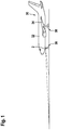
- Figure 1 depicts an airplane 30 comprising an exterior aircraft light unit 2 according to an exemplary embodiment of the invention which is mounted to a front running gear 36 of the airplane 30.
- the exterior aircraft light unit 2 may be mounted to the fuselage 32, a wing 34 or a main running gear 38 of the airplane 30.
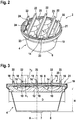
- Figure 2 a shows a perspective view of an exterior aircraft light unit 2 according to an exemplary embodiment of the invention
- Figure 3 shows a sectional view thereof.
- the exterior aircraft light unit 2 comprises a cup-shaped housing 4 having a rear wall 6, which is shown at the bottom of Figures 1 and 2 .
- the rear wall 6 comprises a mounting portion 7 (not shown in Figure 2 ), which is configured for mounting the housing 4 to an aircraft 30, e.g. to the fuselage 32, a wing 34 or a running gear 36, 38 of the airplane 30 (cf. Figure. 1 ).
- the housing 4 may be have a cylindrical shape around an axis A.
- the housing 4 may have a conical shape, as it is shown in Figures 2 and 3 .
- the skilled person will understand that other geometrical shapes of the housing 4 are possible as well.
- the cup-shaped housing 4 may have a maximum diameter D of 150 mm to 250 mm, in particular a maximum diameter D of 175 mm to 225 mm, more particularly a maximum diameter D of 210 mm.
- the height H of the housing may be in the range of 50 mm to 250 mm, in particular in the range of of 175 mm to 225 mm, more particularly close to 210 mm.
- a support plate 8 is provided at the open front side of the housing 4, i.e. at the side opposite to the rear wall 6.
- the support plate 8 which in particular may be a printed circuit board (PCB), supports electrical light sources 10, in particular LEDs.
- the light sources 10 are arranged on the side of the support plate 8 facing the rear wall 6 of the housing 4.
- a reflector plate 12 is arranged between the support plate 8 and the rear wall 6 of the housing 4.
- a plurality of reflectors 14 facing the light sources 10 are formed within the reflector plate 12.
- light, which is emitted from the light sources 10 is reflected by the reflectors 14 to the light emitting front side of the exterior aircraft light unit 2.
- the light emitting front side is the upper side.
- the number of reflectors 14 in particular corresponds with the number of light sources 10, i.e. a reflector 14 is associated with each light source 10, and vice versa.
- the light sources 10 and the reflectors 14 may be arranged in a honeycomb structure, as it is illustrated in Figure 2 , on in any other structure which is suitable for generating the desired light distribution.
- the support plate 8 is provided with windows / openings and/or formed at least partially transparent in order to allow the reflected light to pass through.
- a heat sink 16, 20 is provided on the side of the support plate 8 which is opposite to the light sources 10.
- the heat sink 16, 20 comprises a first heat sink portion 16 and a second heat sink portion 20.
- the first heat sink portion 16 is attached to the support plate 8 and/or the housing 4.
- the second heat sink portion 20 is selectively attachable to the first heat sink portion 16. Attaching the second heat sink portion 20 to the first heat sink portion 18 increases the cooling capacity of the heat sink 16, 20 by increasing the volume and the heat transfer surface of the heat sink 16, 20.
- Figure 4 shows a perspective view of the first heat sink portion 16
- Figure 5 shows a perspective view of the second heat sink portion 20
- Figure 6 shows a perspective view of the second heat sink portion 20 attached to the first heat sink portion 16.
- the first heat sink portion 16 comprises a circular outer support ring 19 (first outer support ring 19), which is attached to the rim of the housing 4, when the first heat sink portion 16 is mounted thereto (cf. Figure 3 ).
- first outer support ring 19 The skilled person will understand that the shape and the diameter of the first outer support ring 19 are set to correspond with the upper rim of the housing 4.
- a plurality of first cooling ribs 18 extend parallel to each other across the first support ring 19.
- the first cooling ribs 18 may have a height h 1 of 5 mm to 10 mm, in particular in the range of 6 mm to 8 mm, more particular 7,5 mm (cf. Figure 3 ).
- the second heat sink portion 20 is basically formed similar to the first heat sink portion 16.
- the second heat sink portion 20 in particular also comprises an outer support ring 21 (second outer support ring 21) and a plurality of second cooling ribs 22 extending parallel to each other across the second outer support ring 21.
- the skilled person will understand that the shape and the diameter of the second outer support ring 21 are set to correspond with the first outer support ring 19.
- the diameter of the second outer support ring 21 in particular is set so that the outer support ring 21 of the second heat sink portion 20 may be positioned over the first support ring 19, as it is shown in Figure 3 .
- the second outer support ring 21 may be at least partly made of a flexible material in order to allow compensating for manufacturing tolerances of the housing 4 and/or the first heat sink portion 18.
- the height of the second cooling ribs 22 may be the same as the height h 1 of the first cooling ribs 18, or it may be different. In the exemplary embodiment shown in the figures, the height of the second cooling ribs 22 is larger than the height h 1 of the first cooling ribs 18.
- the height of the second cooling ribs 22 in particular may be set so that the combined height h 1+2 of the first and second cooling ribs 18, 22 is in the range of 30 mm to 50 mm; in particular in the range of 35 mm to 45 mm, and more particular 45 mm (cf. Figure 3 ).
- the second cooling ribs 22 of the second heat sink portion 20 are positioned in correspondence with the positions of the first cooling ribs 18 of the first heat sink portion 16.
- Channels or grooves 25 are formed in the (lower) sides of the second cooling ribs 22 facing the first cooling ribs 17.
- (upper) tip portions of the first cooling ribs 18 may be introduced into said channels or grooves 25 for attaching the second heat sink portion 20 to the first heat sink portion 16 (cf. Figure 3 ) and providing an efficient and reliable connection between the first and second heat sink portions 16, 20.
- the first heat sink portion 16 and the second heat sink portion 20 have aligned fastening holes. Accordingly, fasteners, such as pins or bolts or screws, can be inserted through the aligned fastening holes for attaching the first and second heat sink portions 16, 20 to each other and to the housing 4. Also, the same fasteners may be used for only attaching the first heat sink portion 16 to the housing 4. By choosing the length of the fasteners accordingly, they may be used in both scenarios, namely for attaching the first heat sink portion 16 only and for attaching both the first heat sink portion 16 and the second heat sink portion 20, thus eliminating the need for different fasteners in different application scenarios.
- fasteners such as pins or bolts or screws
- Figure 7 shows an enlarged detail of Figure 3 illustrating the interaction between the first and second cooling ribs 18, 22.
- the channels or grooves 25 formed in the second cooling ribs 22 and/or the upper portions of the first cooling ribs 18 in particular may be tapered, i.e. the upper tip portions of the first cooling ribs 18 may have a smaller width d than the base portions of the first cooling ribs 18.
- the channels or grooves 25 formed within the second heat sink portion 20 may be wider at their open outer sides facing the first heat sink portion 16 than at the opposing closed ends of the channels or grooves 25.
- first cooling ribs 18 and/or channels or grooves 25 allows to compensate for tolerances in manufacturing and results in a tight and secure connecting between the first and second heat sink portions 16, 20. It further enlarges the area of contact between the first and second cooling ribs 18, 22 resulting in an increased transfer of heat from the first heat sink portion 16 to the second heat sink portion 20.
- an additional heat transfer medium such as a heat transfer paste, may be provided between the first and second heat sink portions 16, 20 in order to enhance the transfer of heat even further.
- the second outer support ring 21 comprises a plurality of fastening lugs 23.
- the fastening lugs 23 allow to securely fix the second heat sink portion 20 to the first heat sink portion 16 by appropriate fastening elements such as bolts or screws, which are not shown in the figures.
- Additional fastening lugs 24 may be provided at the second cooling ribs 22.
- At least one of the first and second heat sink portions 16, 20 may be die-casted or machined from an extruded metal having a high thermal conductivity, such as Aluminum.
- the first and second cooling ribs 18, 22 extend parallel to the main direction of light emission of the exterior aircraft light unit 22.
- the first and second cooling ribs 18, 22 basically do not obstruct or block the light emitted by the exterior aircraft light unit 2 and therefore do not deteriorate the efficiency of the exterior aircraft light unit 2.
- first and second heat sink portions which are configured similar to the first and second heat sink portions 16, 20 shown in the figures, may be attached to the rear side of the reflectors 14 for dissipating heat from the reflectors 14, in particular for dissipating heat from the reflectors 14 that originally stems from the light sources 10.
- a heat sink 16, 20 according to an exemplary embodiment of the invention comprising two portions 16, 20, which may be selectively attached to and separated from another, allows to flexibly adjust the cooling capacity of the heat sink 16, 20 to the actual needs.
- the exterior aircraft light unit 2 In case the exterior aircraft light unit 2 is operated with relatively small power, a small cooling capacity of the heat sink 16, 20 is sufficient. Thus, only a first heat sink portion 16 is mounted to the exterior aircraft light unit 2. As a result, the exterior aircraft light unit 2 has a small size and needs only a relatively small mounting space.
- a second heat sink portion 20 is mounted to the first heat sink portion 16 providing a cooling booster which increases the cooling capacity of the heat sink 16, 20.
- Increasing the cooling capacity of the heat sink 16, 20 in particular is beneficial when the power of the exterior aircraft light unit 2 is above 10 W, as it is usually the case for landing lights, take-off lights, taxi lights, runway turn-off lights and multi-functional light units providing at least two of the functionalities of a landing lights, a take-off light, a taxi light, and a runway turn-off light.
Landscapes
- Engineering & Computer Science (AREA)
- Aviation & Aerospace Engineering (AREA)
- General Engineering & Computer Science (AREA)
- Arrangement Of Elements, Cooling, Sealing, Or The Like Of Lighting Devices (AREA)
Abstract
Description
- The present invention relates to an exterior aircraft light unit comprising a heat sink, in particular a heat sink in thermal connection with one or more light sources.
- Almost all aircraft are equipped with exterior aircraft light units. In particular, large passenger air planes have a wide variety of exterior aircraft light units. Examples include a landing light unit, a take-off light unit, a taxi light unit, a runway turn-off light unit and a multi-functional light unit providing at least two of these functionalities.
- Exterior aircraft light units may be provided with at least one heat sink for dissipating the heat generated by operating the light unit. The power requirements and space envelopes of each of these light units may vary as a function of external parameters which include the type of the aircraft, the respective position of installation of the light unit, such as a wing, a gear or the fuselage of the aircraft. Increased power requirements of the light unit result in an increased need for heat dissipation. This requires a larger heat sink providing more power dissipating ("cooling") capacity. Larger heat sinks, however, need more space for installation, which might not be available in every configuration and/or mounting position.
- It therefore would be beneficial to provide an exterior aircraft light unit that is usable in a variety of different application scenarios.
- Exemplary embodiments of the invention include an exterior aircraft light unit comprising a housing, at least one light source and a heat sink. The housing has a mounting portion, which is configured for mounting the aircraft light unit to an aircraft, in particular to a wing, a gear or the fuselage of the aircraft. The heat sink comprises at least one first heat sink portion, which may be fixable to or integrally formed with the housing of the aircraft light unit. The at least one light source is arranged within the housing and thermally connected to the at least one first heat sink portion in order to allow transferring heat from the at least one light source to the at least one first heat sink portion. The heat sink further comprises at least one second heat sink portion, which is configured to be selectively attachable to the at least one first heat sink portion in a manner which allows heat to transfer from the at least one first heat sink portion to the at least one second heat sink portion. As a result, attaching the second heat sink portion to the first heat sink portion increases the cooling capacity of the heat sink allowing for a greater transfer of heat from the at least one light source than just with just the first heat sink portion alone.
- Exemplary embodiments of the invention also include a set comprising a housing of an exterior aircraft light unit and a first heat sink portion. The housing comprises a mounting portion, which is configured for mounting the aircraft light unit to an aircraft, in particular to a wing, a gear or the fuselage of the aircraft. The housing is configured to accommodate at least one light source in a configuration in which the at least one light source is thermally connected with the at least one first heat sink portion for allowing heat to transfer from the at least one light source to the at least one first heat sink portion. The set further includes at least one second heat sink portion, which is configured to be selectively attachable to the at least one first heat sink portion for increasing the cooling capacity of the heat sink. The at least one second heat sink portion is attachable to the at least one first heat sink portion in a manner which allows heat to transfer from the at least one first heat sink portion to the second heat sink portion.
- Exemplary embodiments of the invention also include an aircraft light unit comprising: a housing, at least one light source, a first heat sink portion in operable communication with the housing and the at least one light source configured to transfer heat from the at least one light source, the aircraft light unit being configured to allow a second heat sink portion to be attached to the aircraft light unit to allow for greater transfer of heat from the at least one light source than is possible with just the first heat sink portion alone. The second heat sink portion may be attachable to the aircraft light unit with no additional parts needed beyond those used to assemble the aircraft light unit with only the first heat sink portion attached.
- Exemplary embodiments of the invention further include an aircraft, in particular an airplane or a helicopter, which comprises at least one exterior aircraft light unit according to an exemplary embodiment of the invention.
- According to exemplary embodiments of the invention, the cooling capacity of the heat sink may be adjusted by selectively attaching or not attaching at least one second heat sink portion to the at least one first heat sink portion. The heat sink of the exterior aircraft light unit has a variable cooling capacity, i.e. a cooling capacity which may be adjusted to the actual needs. Such an exterior aircraft light unit allows for adjusting the cooling capacity and the corresponding size of the heat sink to the respective needs. It in particular allows for reaching a low size of the heat sink and thus of the whole exterior aircraft light unit, while still providing the necessary cooling capacity.
- If the at least one second heat sink portion is attached to the at least one first heat sink portion, the cooling surface and the volume of the heat sink are increased by the surface and the volume of the at least one second heat sink portion, respectively.
- Thus, in the case only a relatively low cooling capacity is required, and the space, which is available for accommodating the heat sink, is restricted, the size of the heat sink may be kept small by not attaching a second heat sink portion to the at least one first heat sink portion. In case sufficient space is available, the second heat sink portion may be attached later in case the user desires to upgrade the performance of the light unit by increasing the electrical power.
- There may be provided a selection of second heat sink portions having different sizes. Provided a selection of second heat sink portions allows adjusting the cooling capacity very closely to the actual needs by selecting and mounting the most appropriate second heat sink portion, i.e. a second heat sink portion having a size which matches the respective cooling requirements as closely as possible. Alternatively or additionally, more than one second heat sink portion may be attached to the at least one first heat sink portion in order to increase the cooling capacity even further.
- In an embodiment, the second heat sink portion is attachable to the aircraft light unit with no additional parts needed beyond those used to assemble the aircraft light unit with only the first heat sink portion attached. This allows for an easy and convenient installation of the second heat sink portion. In particular, no additional fasteners may be needed. The same fasteners can be used with and without the second heat sink portion. The fasteners may have the additional length that is needed for mounting the second heat sink portion.
- In an embodiment, the at least one first heat sink portion comprises a plurality of first cooling ribs, which allow for an effective transfer of heat from the at least one first heat sink portion to the environment of the at least one first heat sink portion.
- In an embodiment, the at least one second heat sink portion comprises a plurality of channels or grooves which are configured for receiving corresponding first cooling ribs, respectively. Such channels or grooves allow to attach the at least one second heat sink portion conveniently and reliably to the at least one first heat sink portion by introducing the first cooling ribs of the at least one first heat sink portion into the channels or grooves formed within the at least one second heat sink portion.
- In an embodiment, at least some of the first cooling ribs and the corresponding channels or grooves of the at least one second heat sink portion are tapered in order to allow for a secure physical contact and heat transfer between the first and second heat sink portions. Tapering the ribs, channels and/or grooves in particular allows for compensating manufacturing tolerances.
- In an embodiment, the at least one second heat sink portion comprises a plurality of second cooling ribs for providing an effective transfer of heat from the at least one second heat sink portion to the environment. Additionally, an additional second heat sink portion may be attached (stacked) to the second cooling ribs for increasing the cooling capacity of the heat sink even further.
- In an embodiment, the first and/or second cooling ribs extend parallel to each other. In an embodiment, each channel or groove formed within the at least one second heat sink portion is associated with a corresponding second cooling rib. This configuration allows to form the channels or grooves so that they extend into the second cooling ribs, which results in a very efficient and light-weight configuration of the at least one second heat sink portion.
- In an embodiment, the cooling ribs extend across an outer support ring. This results in a very efficient and light-weight configuration of the respective heat sink portion. It further allows to mount to the housing of the exterior aircraft light unit easily.
- In an embodiment, the outer support ring is at least partly flexible which allows to compensate for manufacturing tolerances.
- In an embodiment, the first cooling ribs have a height of 5 mm to 10 mm, in particular a height in the range of 6 mm to 8 mm, more particular a height of 7,5 mm. In an embodiment, the combined height of the first and second cooling ribs is in the range of 30 mm to 50 mm; in particular in the range of 35 mm to 45 mm, and more particular the combined height is 45 mm.
- Cooling ribs having such heights provide suitable cooling capacities. First and second heat sink portions having such ribs are convenient to handle and to attach to the housings of exterior aircraft light units.
- In an embodiment, at least one of the first and second heat sink portions is die-casted or machined from an extruded metal having a high thermal conductivity, such as Aluminum.
- In an embodiment, the at least one light source and the at least one first heat sink portion of the heat sink are attached to a common support, in particular to a printed circuit board. The at least one first heat sink portion in particular may be attached to a first side of the common support / printed circuit board, whereas the at least one light source may be attached to an opposing second side of the common support / printed circuit board. Mounting the at least one light source and the at least one first heat sink portion to a common support allows for an effective transfer of heat from the at least one light source to the at least one first heat sink portion.
- In an embodiment, the heat sink is arranged on a light emitting front side of the aircraft light unit. This allows to mount the at least one first heat sink portion to a front-side of a support / printed circuit board supporting the at least one light source on an opposing back-side. The at least one light source may face at least one reflector, which is provided opposite to the at least one light source on the back-side of the support / printed circuit board. Such a configuration results in an exterior aircraft light unit having a compact structure and providing an efficient transfer of heat from the at least one light source to the at least one first heat sink portion.
- In an embodiment, the first and/or second cooling ribs extend parallel to a direction of main light emission of the exterior aircraft light unit for minimizing the obstructing of the light emission caused by the cooling ribs.
- In an embodiment, the heat sink is arranged on a no light emitting rear side of the aircraft light unit, in particular on a back-side of a support / printed circuit board supporting the at least one light source and/or a reflector.
- In an embodiment, the at least one light source is at least one LED. In particular, the exterior aircraft light unit may comprise a plurality of light sources, in particular a plurality of LEDs.
- In an embodiment, the exterior aircraft light unit is an exterior aircraft light unit having an electrical power of more than 10 W, in particular an electrical power in the range of 10 W to 500 W, more particular an electrical power in the range of 50 W to 250 W. A heat sink according to exemplary embodiments of the invention is particularly effective for exterior aircraft light units operating in these power ranges.
- In an embodiment, the exterior aircraft light unit is at least one of a landing light unit, a take-off light unit, a taxi light unit, a runway turn-off light unit and a multi-functional light unit providing at least two of the functionalities of a landing light unit, a take-off light unit, a taxi light unit, and a runway turn-off light unit.
- These light unit are usually operated with high electrical power, in particular an electrical power in the range of 10 W to 500 W, more particularly an electrical power in the range of 50 W to 250 W. Thus, the use of a heat sink according to exemplary embodiments of the invention is particularly effective for these kinds of exterior aircraft light units.
- An exterior aircraft light unit and a heat sink according to exemplary embodiments of the invention are described in more detail below with reference to the enclosed figures.
-
Figure 1 shows anairplane 30 comprising an exterior aircraftlight unit 2 according to an exemplary embodiment of the invention. -
Figure 2 shows a perspective view of an exterior aircraft light unit according to an exemplary embodiment of the invention. -
Figure 3 shows a sectional view of the exterior aircraft light unit shown inFigure 2 . -
Figure 4 shows a perspective view of a first heat sink portion of a heat sink according to an exemplary embodiment of the invention. -
Figure 5 shows a perspective view of a second heat sink portion of a heat sink according to an exemplary embodiment of the invention. -
Figure 6 shows a perspective view of a heat sink according to an exemplary embodiment of the invention in which the second heat sink portion is attached to the first heat sink portion. -
Figure 7 shows an enlarged detail ofFigure 3 illustrating the interaction between the first and second cooling ribs. -
Figure 1 depicts anairplane 30 comprising an exterior aircraftlight unit 2 according to an exemplary embodiment of the invention which is mounted to afront running gear 36 of theairplane 30. Alternatively, the exterior aircraftlight unit 2 may be mounted to thefuselage 32, awing 34 or amain running gear 38 of theairplane 30. -
Figure 2 a shows a perspective view of an exterior aircraftlight unit 2 according to an exemplary embodiment of the invention, andFigure 3 shows a sectional view thereof. - The exterior aircraft
light unit 2 comprises a cup-shapedhousing 4 having arear wall 6, which is shown at the bottom ofFigures 1 and2 . Therear wall 6 comprises a mounting portion 7 (not shown inFigure 2 ), which is configured for mounting thehousing 4 to anaircraft 30, e.g. to thefuselage 32, awing 34 or arunning gear Figure. 1 ). - The
housing 4 may be have a cylindrical shape around an axis A. Alternatively, thehousing 4 may have a conical shape, as it is shown inFigures 2 and 3 . The skilled person will understand that other geometrical shapes of thehousing 4 are possible as well. - The cup-shaped
housing 4 may have a maximum diameter D of 150 mm to 250 mm, in particular a maximum diameter D of 175 mm to 225 mm, more particularly a maximum diameter D of 210 mm. - The height H of the housing may be in the range of 50 mm to 250 mm, in particular in the range of of 175 mm to 225 mm, more particularly close to 210 mm.
- A
support plate 8 is provided at the open front side of thehousing 4, i.e. at the side opposite to therear wall 6. Thesupport plate 8, which in particular may be a printed circuit board (PCB), supports electricallight sources 10, in particular LEDs. In the embodiment shown inFigures 2 and 3 , thelight sources 10 are arranged on the side of thesupport plate 8 facing therear wall 6 of thehousing 4. - A
reflector plate 12 is arranged between thesupport plate 8 and therear wall 6 of thehousing 4. A plurality ofreflectors 14 facing thelight sources 10 are formed within thereflector plate 12. As a result, light, which is emitted from thelight sources 10, is reflected by thereflectors 14 to the light emitting front side of the exterior aircraftlight unit 2. In the orientation of the exterior aircraftlight unit 2 shown inFigures 2 and 3 , the light emitting front side is the upper side. The number ofreflectors 14 in particular corresponds with the number oflight sources 10, i.e. areflector 14 is associated with eachlight source 10, and vice versa. - The
light sources 10 and thereflectors 14 may be arranged in a honeycomb structure, as it is illustrated inFigure 2 , on in any other structure which is suitable for generating the desired light distribution. - The
support plate 8 is provided with windows / openings and/or formed at least partially transparent in order to allow the reflected light to pass through. - A
heat sink support plate 8 which is opposite to thelight sources 10. - The
heat sink heat sink portion 16 and a secondheat sink portion 20. The firstheat sink portion 16 is attached to thesupport plate 8 and/or thehousing 4. The secondheat sink portion 20 is selectively attachable to the firstheat sink portion 16. Attaching the secondheat sink portion 20 to the firstheat sink portion 18 increases the cooling capacity of theheat sink heat sink -
Figure 4 shows a perspective view of the firstheat sink portion 16,Figure 5 shows a perspective view of the secondheat sink portion 20, andFigure 6 shows a perspective view of the secondheat sink portion 20 attached to the firstheat sink portion 16. - The first
heat sink portion 16 comprises a circular outer support ring 19 (first outer support ring 19), which is attached to the rim of thehousing 4, when the firstheat sink portion 16 is mounted thereto (cf.Figure 3 ). The skilled person will understand that the shape and the diameter of the firstouter support ring 19 are set to correspond with the upper rim of thehousing 4. - A plurality of
first cooling ribs 18 extend parallel to each other across thefirst support ring 19. A plurality ofintermediate plates 17, which are at least partially transparent in order to allow emitted light to pass through, extend between thefirst cooling ribs 18. - The
first cooling ribs 18 may have a height h1 of 5 mm to 10 mm, in particular in the range of 6 mm to 8 mm, more particular 7,5 mm (cf.Figure 3 ). - The second
heat sink portion 20 is basically formed similar to the firstheat sink portion 16. The secondheat sink portion 20 in particular also comprises an outer support ring 21 (second outer support ring 21) and a plurality ofsecond cooling ribs 22 extending parallel to each other across the secondouter support ring 21. The skilled person will understand that the shape and the diameter of the secondouter support ring 21 are set to correspond with the firstouter support ring 19. - The diameter of the second
outer support ring 21 in particular is set so that theouter support ring 21 of the secondheat sink portion 20 may be positioned over thefirst support ring 19, as it is shown inFigure 3 . The secondouter support ring 21 may be at least partly made of a flexible material in order to allow compensating for manufacturing tolerances of thehousing 4 and/or the firstheat sink portion 18. - The height of the
second cooling ribs 22 may be the same as the height h1 of thefirst cooling ribs 18, or it may be different. In the exemplary embodiment shown in the figures, the height of thesecond cooling ribs 22 is larger than the height h1 of thefirst cooling ribs 18. The height of thesecond cooling ribs 22 in particular may be set so that the combined height h1+2 of the first andsecond cooling ribs Figure 3 ). - The
second cooling ribs 22 of the secondheat sink portion 20 are positioned in correspondence with the positions of thefirst cooling ribs 18 of the firstheat sink portion 16. Channels orgrooves 25 are formed in the (lower) sides of thesecond cooling ribs 22 facing thefirst cooling ribs 17. As a result, (upper) tip portions of thefirst cooling ribs 18 may be introduced into said channels orgrooves 25 for attaching the secondheat sink portion 20 to the first heat sink portion 16 (cf.Figure 3 ) and providing an efficient and reliable connection between the first and secondheat sink portions - As can be seen from
Figures 4 and 5 as well as fromFigure 2 , the firstheat sink portion 16 and the secondheat sink portion 20 have aligned fastening holes. Accordingly, fasteners, such as pins or bolts or screws, can be inserted through the aligned fastening holes for attaching the first and secondheat sink portions housing 4. Also, the same fasteners may be used for only attaching the firstheat sink portion 16 to thehousing 4. By choosing the length of the fasteners accordingly, they may be used in both scenarios, namely for attaching the firstheat sink portion 16 only and for attaching both the firstheat sink portion 16 and the secondheat sink portion 20, thus eliminating the need for different fasteners in different application scenarios. -
Figure 7 shows an enlarged detail ofFigure 3 illustrating the interaction between the first andsecond cooling ribs - The channels or
grooves 25 formed in thesecond cooling ribs 22 and/or the upper portions of thefirst cooling ribs 18 in particular may be tapered, i.e. the upper tip portions of thefirst cooling ribs 18 may have a smaller width d than the base portions of thefirst cooling ribs 18. Similarly, the channels orgrooves 25 formed within the secondheat sink portion 20 may be wider at their open outer sides facing the firstheat sink portion 16 than at the opposing closed ends of the channels orgrooves 25. - Tapering the
first cooling ribs 18 and/or channels orgrooves 25 allows to compensate for tolerances in manufacturing and results in a tight and secure connecting between the first and secondheat sink portions second cooling ribs heat sink portion 16 to the secondheat sink portion 20. - Optionally, an additional heat transfer medium, such as a heat transfer paste, may be provided between the first and second
heat sink portions - The second
outer support ring 21 comprises a plurality of fastening lugs 23. The fastening lugs 23 allow to securely fix the secondheat sink portion 20 to the firstheat sink portion 16 by appropriate fastening elements such as bolts or screws, which are not shown in the figures. Additional fastening lugs 24 may be provided at thesecond cooling ribs 22. - At least one of the first and second
heat sink portions - In the embodiment shown in the figures, the first and
second cooling ribs light unit 22. As a result, the first andsecond cooling ribs light unit 2 and therefore do not deteriorate the efficiency of the exterior aircraftlight unit 2. - Alternatively or additionally, first and second heat sink portions, which are configured similar to the first and second
heat sink portions reflectors 14 for dissipating heat from thereflectors 14, in particular for dissipating heat from thereflectors 14 that originally stems from thelight sources 10. - A
heat sink portions heat sink - In case the exterior aircraft
light unit 2 is operated with relatively small power, a small cooling capacity of theheat sink heat sink portion 16 is mounted to the exterior aircraftlight unit 2. As a result, the exterior aircraftlight unit 2 has a small size and needs only a relatively small mounting space. - In case the exterior aircraft
light unit 2 is to be operated with more power, more cooling capacity is needed. Thus, a secondheat sink portion 20 is mounted to the firstheat sink portion 16 providing a cooling booster which increases the cooling capacity of theheat sink - Increasing the cooling capacity of the
heat sink light unit 2 is above 10 W, as it is usually the case for landing lights, take-off lights, taxi lights, runway turn-off lights and multi-functional light units providing at least two of the functionalities of a landing lights, a take-off light, a taxi light, and a runway turn-off light. - While the invention has been described with reference to exemplary embodiments, it will be understood by those skilled in the art that various changes may be made and equivalents may be substituted for elements thereof without departing from the scope of the invention. In addition many modifications may be made to adopt a particular situation or material to the teachings of the invention without departing from the essential scope thereof. Therefore, it is intended that the invention not be limited to the particular embodiment disclosed, but that the invention include all embodiments falling within the scope of the following claims.
Claims (15)
- Exterior aircraft light unit (2) comprising:a housing (4) including a mounting portion (6), which is configured for mounting the aircraft light unit (2) to an aircraft (30);at least one light source (10); anda heat sink (16, 20);wherein the heat sink (16, 20) comprises:at least one first heat sink portion (16), which is thermally connected with the at least one light source (10) for transferring heat from the at least one light source (10) to the at least one first heat sink portion (16); andat least one second heat sink portion (20), which is configured to be selectively attachable to the at least one first heat sink portion (16).
- Exterior aircraft light unit (2) according to claim 1, wherein the at least one first heat sink portion (16) comprises a plurality of first cooling ribs (18).
- Exterior aircraft light unit (2) according to claim 2, wherein the at least one second heat sink portion (20) comprises a plurality of channels or grooves (25) which are configured for receiving corresponding first cooling ribs (18) when the second heat sink portion (20) is attached to the at least one first heat sink portion (16).
- Exterior aircraft light unit (2) according to claim 3, wherein at least some of the first cooling ribs (18) and the corresponding channels or grooves (25) of the at least one second heat sink portion (20) are tapered.
- Exterior aircraft light unit (2) according to claim 3 or 4, wherein the at least one second heat sink portion (20) comprises a plurality of second cooling ribs (22), wherein in particular each channel or groove is associated with a corresponding second cooling rib (22).
- Exterior aircraft light unit (2) according to any of claims 2 to 5, wherein the first and/or second cooling ribs (18, 22) extend parallel to each other.
- Exterior aircraft light unit (2) according to any of claims 2 to 6, wherein the first cooling ribs (18) extend across a first support ring (19), which in particular is attached to the housing (4) of the exterior aircraft light unit (2).
- Exterior aircraft light unit (2) according to any of claims 2 to 7, wherein the second cooling ribs (22) extend across a second support ring (21), which in particular is at least partly flexible.
- Exterior aircraft light unit (2) according to any of claims 2 to 9, wherein the first cooling ribs (18) have a height (h1) of 5 mm to 10 mm, in particular in the range of 6 mm to 8 mm, more particular 7,5 mm and/or, wherein the combined height (h1+2) of the first and second cooling ribs (18, 22) is in the range of 30 mm to 50 mm; in particular in the range of 35 mm to 45 mm, and more particular 45 mm.
- Exterior aircraft light unit (2) according to any of the previous claims, wherein the at least one light source (10) and the at least one first heat sink portion (16) are attached to a common support (8), in particular to a printed circuit board.
- Exterior aircraft light unit (2) according to any of the previous claims, wherein the heat sink (16, 18) is arranged on a light emitting front side of the aircraft light unit (2), wherein the first and/or second cooling ribs (22) in particular extend parallel to a direction of main light emission of the exterior aircraft light unit (2).
- Exterior aircraft light unit (2) according to any of the previous claims, wherein the second heat sink portion (16) is attachable to the aircraft light unit (2) with no additional parts needed beyond those used to assemble the aircraft light unit (2) with only the first heat sink portion (10) attached.
- Exterior aircraft light unit (2) according to any of the previous claims, wherein the aircraft light unit (2) is operated with an electrical power of more than 10 W, and/or wherein the aircraft light unit (2) is at least one of a landing light unit, a take-off light unit, a taxi light unit, a runway turn-off light unit and a multi-functional light unit providing at least two of the functionalities of a landing light unit, a take-off light unit, a taxis light unit, a runway turn-off light unit.
- Aircraft (30), in particular an airplane (30) or helicopter, comprising at least one exterior aircraft light unit (2) according to one of the preceding claims.
- Set comprising
a housing (4) of an exterior aircraft light unit (2) with a mounting portion (6), which is configured for mounting the housing (4) to an aircraft (30);
at least one first heat sink portion (16); and
at least one second heat sink portion (20), which is configured to be selectively attachable to the at least one first heat sink portion (16) for providing a heat sink (16, 20) having an increased cooling capacity;
wherein the housing (4) is configured to accommodate at least one light source (10) so that the at least one light source (10) is thermal connected with the at least one first heat sink portion (16) for transferring heat from the at least one light source (10) to the at least one first heat sink portion (16).
Priority Applications (2)
| Application Number | Priority Date | Filing Date | Title |
|---|---|---|---|
| EP17172033.7A EP3403937B1 (en) | 2017-05-19 | 2017-05-19 | Exterior aircraft light unit |
| US15/975,975 US10604275B2 (en) | 2017-05-19 | 2018-05-10 | Exterior aircraft light unit |
Applications Claiming Priority (1)
| Application Number | Priority Date | Filing Date | Title |
|---|---|---|---|
| EP17172033.7A EP3403937B1 (en) | 2017-05-19 | 2017-05-19 | Exterior aircraft light unit |
Publications (2)
| Publication Number | Publication Date |
|---|---|
| EP3403937A1 true EP3403937A1 (en) | 2018-11-21 |
| EP3403937B1 EP3403937B1 (en) | 2021-01-13 |
Family
ID=58738978
Family Applications (1)
| Application Number | Title | Priority Date | Filing Date |
|---|---|---|---|
| EP17172033.7A Not-in-force EP3403937B1 (en) | 2017-05-19 | 2017-05-19 | Exterior aircraft light unit |
Country Status (2)
| Country | Link |
|---|---|
| US (1) | US10604275B2 (en) |
| EP (1) | EP3403937B1 (en) |
Families Citing this family (1)
| Publication number | Priority date | Publication date | Assignee | Title |
|---|---|---|---|---|
| CN115971443B (en) * | 2023-01-16 | 2026-03-10 | 厦门普为光电科技有限公司 | Method for manufacturing common mold of industrial lighting device |
Citations (11)
| Publication number | Priority date | Publication date | Assignee | Title |
|---|---|---|---|---|
| US5247734A (en) * | 1992-11-09 | 1993-09-28 | Motorola, Inc. | Method and apparatus of an improved heat sink |
| US20110277978A1 (en) * | 2010-05-11 | 2011-11-17 | Chun-Po Lai | Snap-fit type heat sink module |
| US20120026737A1 (en) * | 2009-04-03 | 2012-02-02 | Vishay Electronic Gmbh | Outdoor lighting unit |
| US20130105132A1 (en) * | 2011-10-26 | 2013-05-02 | Tsung-Hsien Huang | Heat sink fin and heat sink device |
| US20130249375A1 (en) * | 2012-03-21 | 2013-09-26 | George W. Panagotacos | Anti-icing solid state aircraft lamp assembly with defroster apparatus, system, and method |
| EP2767757A1 (en) * | 2011-10-10 | 2014-08-20 | Posco Led Company Ltd | Optical semiconductor-based lighting apparatus |
| US20150062909A1 (en) * | 2012-04-13 | 2015-03-05 | Cree, Inc. | Led lamp |
| US20150377452A1 (en) * | 2014-06-26 | 2015-12-31 | Phillip Walesa | Parabolic quadrant led light fixture |
| US20160081225A1 (en) * | 2012-04-17 | 2016-03-17 | Molex, Llc | Stackable rotated heat sink |
| WO2016151441A1 (en) * | 2015-03-20 | 2016-09-29 | Sabic Global Technologies B.V. | Plastic heat sink for luminaires |
| US20160347474A1 (en) * | 2015-05-28 | 2016-12-01 | Zodiac Aero Electric | Lighting device for aircraft allowing the integration of additional functions at its center |
Family Cites Families (7)
| Publication number | Priority date | Publication date | Assignee | Title |
|---|---|---|---|---|
| DE3024748C2 (en) * | 1980-06-30 | 1986-09-04 | Aluminium Walzwerke Singen Gmbh, 7700 Singen | Heat sinks for semiconductor components |
| US5574626A (en) * | 1995-07-12 | 1996-11-12 | Unisys Corporation | Add-on heat sink |
| US7434970B2 (en) | 2004-03-12 | 2008-10-14 | Honeywell International Inc. | Multi-platform LED-based aircraft rear position light |
| US7275848B2 (en) * | 2005-02-16 | 2007-10-02 | Visteon Global Technologies, Inc. | Headlamp assembly having cooling channel |
| DE102009022071A1 (en) | 2009-05-20 | 2010-11-25 | Osram Gesellschaft mit beschränkter Haftung | Heat sink for a lighting device |
| WO2011138363A1 (en) * | 2010-05-05 | 2011-11-10 | Alexiou & Tryde Holding Aps | Led lamp assembly |
| CN102840567A (en) * | 2011-06-21 | 2012-12-26 | 欧司朗股份有限公司 | Heat sink and manufacture method thereof |
-
2017
- 2017-05-19 EP EP17172033.7A patent/EP3403937B1/en not_active Not-in-force
-
2018
- 2018-05-10 US US15/975,975 patent/US10604275B2/en not_active Expired - Fee Related
Patent Citations (11)
| Publication number | Priority date | Publication date | Assignee | Title |
|---|---|---|---|---|
| US5247734A (en) * | 1992-11-09 | 1993-09-28 | Motorola, Inc. | Method and apparatus of an improved heat sink |
| US20120026737A1 (en) * | 2009-04-03 | 2012-02-02 | Vishay Electronic Gmbh | Outdoor lighting unit |
| US20110277978A1 (en) * | 2010-05-11 | 2011-11-17 | Chun-Po Lai | Snap-fit type heat sink module |
| EP2767757A1 (en) * | 2011-10-10 | 2014-08-20 | Posco Led Company Ltd | Optical semiconductor-based lighting apparatus |
| US20130105132A1 (en) * | 2011-10-26 | 2013-05-02 | Tsung-Hsien Huang | Heat sink fin and heat sink device |
| US20130249375A1 (en) * | 2012-03-21 | 2013-09-26 | George W. Panagotacos | Anti-icing solid state aircraft lamp assembly with defroster apparatus, system, and method |
| US20150062909A1 (en) * | 2012-04-13 | 2015-03-05 | Cree, Inc. | Led lamp |
| US20160081225A1 (en) * | 2012-04-17 | 2016-03-17 | Molex, Llc | Stackable rotated heat sink |
| US20150377452A1 (en) * | 2014-06-26 | 2015-12-31 | Phillip Walesa | Parabolic quadrant led light fixture |
| WO2016151441A1 (en) * | 2015-03-20 | 2016-09-29 | Sabic Global Technologies B.V. | Plastic heat sink for luminaires |
| US20160347474A1 (en) * | 2015-05-28 | 2016-12-01 | Zodiac Aero Electric | Lighting device for aircraft allowing the integration of additional functions at its center |
Also Published As
| Publication number | Publication date |
|---|---|
| US20180334265A1 (en) | 2018-11-22 |
| US10604275B2 (en) | 2020-03-31 |
| EP3403937B1 (en) | 2021-01-13 |
Similar Documents
| Publication | Publication Date | Title |
|---|---|---|
| EP1561993B1 (en) | LED lamps and method of cooling their LED | |
| US7923748B2 (en) | Integrated LED heat sink | |
| US7794114B2 (en) | Methods and apparatus for improved heat spreading in solid state lighting systems | |
| US7988321B2 (en) | LED lamp | |
| EP3180968B1 (en) | An led lighting apparatus with an open frame network of light modules | |
| US20190360681A1 (en) | LED Lamp for Vehicles | |
| US10145551B2 (en) | LED lamp with active chamber cooling | |
| US20100242519A1 (en) | Heat sink and lighting device comprising a heat sink | |
| US20120224360A1 (en) | Illumination lamp | |
| US10129960B2 (en) | Antenna arrangement for a solid-state lamp | |
| EP3315847B1 (en) | Led searchlight and method | |
| EP1918204B1 (en) | Integrated searchlight lighthead | |
| US10604275B2 (en) | Exterior aircraft light unit | |
| CN213955024U (en) | High-power LED lamp easy to radiate heat | |
| US10851964B2 (en) | Lighting fixture for vehicle | |
| US10569902B2 (en) | Exterior aircraft light unit | |
| US9279576B2 (en) | Light fixture with interchangeable heatsink trays and reflectors | |
| US20210041095A1 (en) | Led luminaire bracket with shielded integral mounted drivers | |
| US12529474B2 (en) | Electronics housing assembly with improved heat dissipation | |
| CN215043777U (en) | Lighting unmanned aerial vehicle | |
| US20180187879A1 (en) | Modular illumination device for a marine environment | |
| CN210004213U (en) | LED module mounting structure | |
| CN212480865U (en) | Lamp with good heat dissipation effect | |
| KR20150046546A (en) | Heat radiating structure of LED lamp for improved heat dissipation |
Legal Events
| Date | Code | Title | Description |
|---|---|---|---|
| PUAI | Public reference made under article 153(3) epc to a published international application that has entered the european phase |
Free format text: ORIGINAL CODE: 0009012 |
|
| STAA | Information on the status of an ep patent application or granted ep patent |
Free format text: STATUS: THE APPLICATION HAS BEEN PUBLISHED |
|
| AK | Designated contracting states |
Kind code of ref document: A1 Designated state(s): AL AT BE BG CH CY CZ DE DK EE ES FI FR GB GR HR HU IE IS IT LI LT LU LV MC MK MT NL NO PL PT RO RS SE SI SK SM TR |
|
| AX | Request for extension of the european patent |
Extension state: BA ME |
|
| STAA | Information on the status of an ep patent application or granted ep patent |
Free format text: STATUS: REQUEST FOR EXAMINATION WAS MADE |
|
| 17P | Request for examination filed |
Effective date: 20190516 |
|
| RBV | Designated contracting states (corrected) |
Designated state(s): AL AT BE BG CH CY CZ DE DK EE ES FI FR GB GR HR HU IE IS IT LI LT LU LV MC MK MT NL NO PL PT RO RS SE SI SK SM TR |
|
| STAA | Information on the status of an ep patent application or granted ep patent |
Free format text: STATUS: EXAMINATION IS IN PROGRESS |
|
| 17Q | First examination report despatched |
Effective date: 20190924 |
|
| RIC1 | Information provided on ipc code assigned before grant |
Ipc: B64D 47/06 20060101ALI20200414BHEP Ipc: B64D 47/04 20060101AFI20200414BHEP |
|
| GRAP | Despatch of communication of intention to grant a patent |
Free format text: ORIGINAL CODE: EPIDOSNIGR1 |
|
| STAA | Information on the status of an ep patent application or granted ep patent |
Free format text: STATUS: GRANT OF PATENT IS INTENDED |
|
| INTG | Intention to grant announced |
Effective date: 20200602 |
|
| RIN1 | Information on inventor provided before grant (corrected) |
Inventor name: HESSLING-VON HEIMENDAHL, ANDRE Inventor name: JHA, ANIL KUMAR |
|
| GRAS | Grant fee paid |
Free format text: ORIGINAL CODE: EPIDOSNIGR3 |
|
| GRAJ | Information related to disapproval of communication of intention to grant by the applicant or resumption of examination proceedings by the epo deleted |
Free format text: ORIGINAL CODE: EPIDOSDIGR1 |
|
| GRAL | Information related to payment of fee for publishing/printing deleted |
Free format text: ORIGINAL CODE: EPIDOSDIGR3 |
|
| STAA | Information on the status of an ep patent application or granted ep patent |
Free format text: STATUS: EXAMINATION IS IN PROGRESS |
|
| INTC | Intention to grant announced (deleted) | ||
| GRAR | Information related to intention to grant a patent recorded |
Free format text: ORIGINAL CODE: EPIDOSNIGR71 |
|
| STAA | Information on the status of an ep patent application or granted ep patent |
Free format text: STATUS: GRANT OF PATENT IS INTENDED |
|
| GRAA | (expected) grant |
Free format text: ORIGINAL CODE: 0009210 |
|
| STAA | Information on the status of an ep patent application or granted ep patent |
Free format text: STATUS: THE PATENT HAS BEEN GRANTED |
|
| AK | Designated contracting states |
Kind code of ref document: B1 Designated state(s): AL AT BE BG CH CY CZ DE DK EE ES FI FR GB GR HR HU IE IS IT LI LT LU LV MC MK MT NL NO PL PT RO RS SE SI SK SM TR |
|
| INTG | Intention to grant announced |
Effective date: 20201208 |
|
| REG | Reference to a national code |
Ref country code: GB Ref legal event code: FG4D |
|
| REG | Reference to a national code |
Ref country code: CH Ref legal event code: EP |
|
| REG | Reference to a national code |
Ref country code: IE Ref legal event code: FG4D |
|
| REG | Reference to a national code |
Ref country code: DE Ref legal event code: R096 Ref document number: 602017031275 Country of ref document: DE |
|
| REG | Reference to a national code |
Ref country code: AT Ref legal event code: REF Ref document number: 1354387 Country of ref document: AT Kind code of ref document: T Effective date: 20210215 |
|
| REG | Reference to a national code |
Ref country code: AT Ref legal event code: MK05 Ref document number: 1354387 Country of ref document: AT Kind code of ref document: T Effective date: 20210113 |
|
| REG | Reference to a national code |
Ref country code: NL Ref legal event code: MP Effective date: 20210113 |
|
| REG | Reference to a national code |
Ref country code: LT Ref legal event code: MG9D |
|
| PG25 | Lapsed in a contracting state [announced via postgrant information from national office to epo] |
Ref country code: HR Free format text: LAPSE BECAUSE OF FAILURE TO SUBMIT A TRANSLATION OF THE DESCRIPTION OR TO PAY THE FEE WITHIN THE PRESCRIBED TIME-LIMIT Effective date: 20210113 Ref country code: FI Free format text: LAPSE BECAUSE OF FAILURE TO SUBMIT A TRANSLATION OF THE DESCRIPTION OR TO PAY THE FEE WITHIN THE PRESCRIBED TIME-LIMIT Effective date: 20210113 Ref country code: GR Free format text: LAPSE BECAUSE OF FAILURE TO SUBMIT A TRANSLATION OF THE DESCRIPTION OR TO PAY THE FEE WITHIN THE PRESCRIBED TIME-LIMIT Effective date: 20210414 Ref country code: NO Free format text: LAPSE BECAUSE OF FAILURE TO SUBMIT A TRANSLATION OF THE DESCRIPTION OR TO PAY THE FEE WITHIN THE PRESCRIBED TIME-LIMIT Effective date: 20210413 Ref country code: PT Free format text: LAPSE BECAUSE OF FAILURE TO SUBMIT A TRANSLATION OF THE DESCRIPTION OR TO PAY THE FEE WITHIN THE PRESCRIBED TIME-LIMIT Effective date: 20210513 Ref country code: LT Free format text: LAPSE BECAUSE OF FAILURE TO SUBMIT A TRANSLATION OF THE DESCRIPTION OR TO PAY THE FEE WITHIN THE PRESCRIBED TIME-LIMIT Effective date: 20210113 Ref country code: BG Free format text: LAPSE BECAUSE OF FAILURE TO SUBMIT A TRANSLATION OF THE DESCRIPTION OR TO PAY THE FEE WITHIN THE PRESCRIBED TIME-LIMIT Effective date: 20210413 |
|
| PG25 | Lapsed in a contracting state [announced via postgrant information from national office to epo] |
Ref country code: AT Free format text: LAPSE BECAUSE OF FAILURE TO SUBMIT A TRANSLATION OF THE DESCRIPTION OR TO PAY THE FEE WITHIN THE PRESCRIBED TIME-LIMIT Effective date: 20210113 Ref country code: PL Free format text: LAPSE BECAUSE OF FAILURE TO SUBMIT A TRANSLATION OF THE DESCRIPTION OR TO PAY THE FEE WITHIN THE PRESCRIBED TIME-LIMIT Effective date: 20210113 Ref country code: RS Free format text: LAPSE BECAUSE OF FAILURE TO SUBMIT A TRANSLATION OF THE DESCRIPTION OR TO PAY THE FEE WITHIN THE PRESCRIBED TIME-LIMIT Effective date: 20210113 Ref country code: LV Free format text: LAPSE BECAUSE OF FAILURE TO SUBMIT A TRANSLATION OF THE DESCRIPTION OR TO PAY THE FEE WITHIN THE PRESCRIBED TIME-LIMIT Effective date: 20210113 Ref country code: SE Free format text: LAPSE BECAUSE OF FAILURE TO SUBMIT A TRANSLATION OF THE DESCRIPTION OR TO PAY THE FEE WITHIN THE PRESCRIBED TIME-LIMIT Effective date: 20210113 |
|
| PG25 | Lapsed in a contracting state [announced via postgrant information from national office to epo] |
Ref country code: IS Free format text: LAPSE BECAUSE OF FAILURE TO SUBMIT A TRANSLATION OF THE DESCRIPTION OR TO PAY THE FEE WITHIN THE PRESCRIBED TIME-LIMIT Effective date: 20210513 |
|
| REG | Reference to a national code |
Ref country code: DE Ref legal event code: R097 Ref document number: 602017031275 Country of ref document: DE |
|
| PG25 | Lapsed in a contracting state [announced via postgrant information from national office to epo] |
Ref country code: SM Free format text: LAPSE BECAUSE OF FAILURE TO SUBMIT A TRANSLATION OF THE DESCRIPTION OR TO PAY THE FEE WITHIN THE PRESCRIBED TIME-LIMIT Effective date: 20210113 Ref country code: CZ Free format text: LAPSE BECAUSE OF FAILURE TO SUBMIT A TRANSLATION OF THE DESCRIPTION OR TO PAY THE FEE WITHIN THE PRESCRIBED TIME-LIMIT Effective date: 20210113 Ref country code: EE Free format text: LAPSE BECAUSE OF FAILURE TO SUBMIT A TRANSLATION OF THE DESCRIPTION OR TO PAY THE FEE WITHIN THE PRESCRIBED TIME-LIMIT Effective date: 20210113 |
|
| PLBE | No opposition filed within time limit |
Free format text: ORIGINAL CODE: 0009261 |
|
| STAA | Information on the status of an ep patent application or granted ep patent |
Free format text: STATUS: NO OPPOSITION FILED WITHIN TIME LIMIT |
|
| PG25 | Lapsed in a contracting state [announced via postgrant information from national office to epo] |
Ref country code: DK Free format text: LAPSE BECAUSE OF FAILURE TO SUBMIT A TRANSLATION OF THE DESCRIPTION OR TO PAY THE FEE WITHIN THE PRESCRIBED TIME-LIMIT Effective date: 20210113 Ref country code: RO Free format text: LAPSE BECAUSE OF FAILURE TO SUBMIT A TRANSLATION OF THE DESCRIPTION OR TO PAY THE FEE WITHIN THE PRESCRIBED TIME-LIMIT Effective date: 20210113 Ref country code: SK Free format text: LAPSE BECAUSE OF FAILURE TO SUBMIT A TRANSLATION OF THE DESCRIPTION OR TO PAY THE FEE WITHIN THE PRESCRIBED TIME-LIMIT Effective date: 20210113 |
|
| 26N | No opposition filed |
Effective date: 20211014 |
|
| REG | Reference to a national code |
Ref country code: CH Ref legal event code: PL |
|
| PG25 | Lapsed in a contracting state [announced via postgrant information from national office to epo] |
Ref country code: ES Free format text: LAPSE BECAUSE OF FAILURE TO SUBMIT A TRANSLATION OF THE DESCRIPTION OR TO PAY THE FEE WITHIN THE PRESCRIBED TIME-LIMIT Effective date: 20210113 Ref country code: CH Free format text: LAPSE BECAUSE OF NON-PAYMENT OF DUE FEES Effective date: 20210531 Ref country code: AL Free format text: LAPSE BECAUSE OF FAILURE TO SUBMIT A TRANSLATION OF THE DESCRIPTION OR TO PAY THE FEE WITHIN THE PRESCRIBED TIME-LIMIT Effective date: 20210113 Ref country code: LI Free format text: LAPSE BECAUSE OF NON-PAYMENT OF DUE FEES Effective date: 20210531 Ref country code: LU Free format text: LAPSE BECAUSE OF NON-PAYMENT OF DUE FEES Effective date: 20210519 Ref country code: MC Free format text: LAPSE BECAUSE OF FAILURE TO SUBMIT A TRANSLATION OF THE DESCRIPTION OR TO PAY THE FEE WITHIN THE PRESCRIBED TIME-LIMIT Effective date: 20210113 |
|
| REG | Reference to a national code |
Ref country code: BE Ref legal event code: MM Effective date: 20210531 |
|
| PG25 | Lapsed in a contracting state [announced via postgrant information from national office to epo] |
Ref country code: SI Free format text: LAPSE BECAUSE OF FAILURE TO SUBMIT A TRANSLATION OF THE DESCRIPTION OR TO PAY THE FEE WITHIN THE PRESCRIBED TIME-LIMIT Effective date: 20210113 |
|
| PG25 | Lapsed in a contracting state [announced via postgrant information from national office to epo] |
Ref country code: IT Free format text: LAPSE BECAUSE OF FAILURE TO SUBMIT A TRANSLATION OF THE DESCRIPTION OR TO PAY THE FEE WITHIN THE PRESCRIBED TIME-LIMIT Effective date: 20210113 Ref country code: IE Free format text: LAPSE BECAUSE OF NON-PAYMENT OF DUE FEES Effective date: 20210519 |
|
| PG25 | Lapsed in a contracting state [announced via postgrant information from national office to epo] |
Ref country code: IS Free format text: LAPSE BECAUSE OF FAILURE TO SUBMIT A TRANSLATION OF THE DESCRIPTION OR TO PAY THE FEE WITHIN THE PRESCRIBED TIME-LIMIT Effective date: 20210513 |
|
| PG25 | Lapsed in a contracting state [announced via postgrant information from national office to epo] |
Ref country code: BE Free format text: LAPSE BECAUSE OF NON-PAYMENT OF DUE FEES Effective date: 20210531 |
|
| PGFP | Annual fee paid to national office [announced via postgrant information from national office to epo] |
Ref country code: GB Payment date: 20220425 Year of fee payment: 6 Ref country code: FR Payment date: 20220421 Year of fee payment: 6 Ref country code: DE Payment date: 20220420 Year of fee payment: 6 |
|
| PG25 | Lapsed in a contracting state [announced via postgrant information from national office to epo] |
Ref country code: NL Free format text: LAPSE BECAUSE OF NON-PAYMENT OF DUE FEES Effective date: 20210113 Ref country code: CY Free format text: LAPSE BECAUSE OF FAILURE TO SUBMIT A TRANSLATION OF THE DESCRIPTION OR TO PAY THE FEE WITHIN THE PRESCRIBED TIME-LIMIT Effective date: 20210113 |
|
| PG25 | Lapsed in a contracting state [announced via postgrant information from national office to epo] |
Ref country code: HU Free format text: LAPSE BECAUSE OF FAILURE TO SUBMIT A TRANSLATION OF THE DESCRIPTION OR TO PAY THE FEE WITHIN THE PRESCRIBED TIME-LIMIT; INVALID AB INITIO Effective date: 20170519 |
|
| REG | Reference to a national code |
Ref country code: DE Ref legal event code: R119 Ref document number: 602017031275 Country of ref document: DE |
|
| GBPC | Gb: european patent ceased through non-payment of renewal fee |
Effective date: 20230519 |
|
| PG25 | Lapsed in a contracting state [announced via postgrant information from national office to epo] |
Ref country code: MK Free format text: LAPSE BECAUSE OF FAILURE TO SUBMIT A TRANSLATION OF THE DESCRIPTION OR TO PAY THE FEE WITHIN THE PRESCRIBED TIME-LIMIT Effective date: 20210113 Ref country code: DE Free format text: LAPSE BECAUSE OF NON-PAYMENT OF DUE FEES Effective date: 20231201 Ref country code: GB Free format text: LAPSE BECAUSE OF NON-PAYMENT OF DUE FEES Effective date: 20230519 |
|
| PG25 | Lapsed in a contracting state [announced via postgrant information from national office to epo] |
Ref country code: FR Free format text: LAPSE BECAUSE OF NON-PAYMENT OF DUE FEES Effective date: 20230531 |
|
| PG25 | Lapsed in a contracting state [announced via postgrant information from national office to epo] |
Ref country code: TR Free format text: LAPSE BECAUSE OF FAILURE TO SUBMIT A TRANSLATION OF THE DESCRIPTION OR TO PAY THE FEE WITHIN THE PRESCRIBED TIME-LIMIT Effective date: 20210113 |
|
| PG25 | Lapsed in a contracting state [announced via postgrant information from national office to epo] |
Ref country code: MT Free format text: LAPSE BECAUSE OF FAILURE TO SUBMIT A TRANSLATION OF THE DESCRIPTION OR TO PAY THE FEE WITHIN THE PRESCRIBED TIME-LIMIT Effective date: 20210113 |