EP3403891A1 - Deceleration pedal control for braking systems - Google Patents
Deceleration pedal control for braking systems Download PDFInfo
- Publication number
- EP3403891A1 EP3403891A1 EP18172307.3A EP18172307A EP3403891A1 EP 3403891 A1 EP3403891 A1 EP 3403891A1 EP 18172307 A EP18172307 A EP 18172307A EP 3403891 A1 EP3403891 A1 EP 3403891A1
- Authority
- EP
- European Patent Office
- Prior art keywords
- pedal
- command
- braking
- deceleration
- aircraft
- Prior art date
- Legal status (The legal status is an assumption and is not a legal conclusion. Google has not performed a legal analysis and makes no representation as to the accuracy of the status listed.)
- Granted
Links
Images


Classifications
-
- B—PERFORMING OPERATIONS; TRANSPORTING
- B60—VEHICLES IN GENERAL
- B60T—VEHICLE BRAKE CONTROL SYSTEMS OR PARTS THEREOF; BRAKE CONTROL SYSTEMS OR PARTS THEREOF, IN GENERAL; ARRANGEMENT OF BRAKING ELEMENTS ON VEHICLES IN GENERAL; PORTABLE DEVICES FOR PREVENTING UNWANTED MOVEMENT OF VEHICLES; VEHICLE MODIFICATIONS TO FACILITATE COOLING OF BRAKES
- B60T8/00—Arrangements for adjusting wheel-braking force to meet varying vehicular or ground-surface conditions, e.g. limiting or varying distribution of braking force
- B60T8/17—Using electrical or electronic regulation means to control braking
- B60T8/172—Determining control parameters used in the regulation, e.g. by calculations involving measured or detected parameters
-
- B—PERFORMING OPERATIONS; TRANSPORTING
- B60—VEHICLES IN GENERAL
- B60T—VEHICLE BRAKE CONTROL SYSTEMS OR PARTS THEREOF; BRAKE CONTROL SYSTEMS OR PARTS THEREOF, IN GENERAL; ARRANGEMENT OF BRAKING ELEMENTS ON VEHICLES IN GENERAL; PORTABLE DEVICES FOR PREVENTING UNWANTED MOVEMENT OF VEHICLES; VEHICLE MODIFICATIONS TO FACILITATE COOLING OF BRAKES
- B60T7/00—Brake-action initiating means
- B60T7/02—Brake-action initiating means for personal initiation
- B60T7/04—Brake-action initiating means for personal initiation foot actuated
- B60T7/042—Brake-action initiating means for personal initiation foot actuated by electrical means, e.g. using travel or force sensors
-
- B—PERFORMING OPERATIONS; TRANSPORTING
- B60—VEHICLES IN GENERAL
- B60T—VEHICLE BRAKE CONTROL SYSTEMS OR PARTS THEREOF; BRAKE CONTROL SYSTEMS OR PARTS THEREOF, IN GENERAL; ARRANGEMENT OF BRAKING ELEMENTS ON VEHICLES IN GENERAL; PORTABLE DEVICES FOR PREVENTING UNWANTED MOVEMENT OF VEHICLES; VEHICLE MODIFICATIONS TO FACILITATE COOLING OF BRAKES
- B60T8/00—Arrangements for adjusting wheel-braking force to meet varying vehicular or ground-surface conditions, e.g. limiting or varying distribution of braking force
- B60T8/17—Using electrical or electronic regulation means to control braking
- B60T8/1701—Braking or traction control means specially adapted for particular types of vehicles
- B60T8/1703—Braking or traction control means specially adapted for particular types of vehicles for aircrafts
-
- B—PERFORMING OPERATIONS; TRANSPORTING
- B60—VEHICLES IN GENERAL
- B60T—VEHICLE BRAKE CONTROL SYSTEMS OR PARTS THEREOF; BRAKE CONTROL SYSTEMS OR PARTS THEREOF, IN GENERAL; ARRANGEMENT OF BRAKING ELEMENTS ON VEHICLES IN GENERAL; PORTABLE DEVICES FOR PREVENTING UNWANTED MOVEMENT OF VEHICLES; VEHICLE MODIFICATIONS TO FACILITATE COOLING OF BRAKES
- B60T8/00—Arrangements for adjusting wheel-braking force to meet varying vehicular or ground-surface conditions, e.g. limiting or varying distribution of braking force
- B60T8/17—Using electrical or electronic regulation means to control braking
- B60T8/171—Detecting parameters used in the regulation; Measuring values used in the regulation
-
- B—PERFORMING OPERATIONS; TRANSPORTING
- B60—VEHICLES IN GENERAL
- B60T—VEHICLE BRAKE CONTROL SYSTEMS OR PARTS THEREOF; BRAKE CONTROL SYSTEMS OR PARTS THEREOF, IN GENERAL; ARRANGEMENT OF BRAKING ELEMENTS ON VEHICLES IN GENERAL; PORTABLE DEVICES FOR PREVENTING UNWANTED MOVEMENT OF VEHICLES; VEHICLE MODIFICATIONS TO FACILITATE COOLING OF BRAKES
- B60T8/00—Arrangements for adjusting wheel-braking force to meet varying vehicular or ground-surface conditions, e.g. limiting or varying distribution of braking force
- B60T8/17—Using electrical or electronic regulation means to control braking
- B60T8/176—Brake regulation specially adapted to prevent excessive wheel slip during vehicle deceleration, e.g. ABS
- B60T8/1761—Brake regulation specially adapted to prevent excessive wheel slip during vehicle deceleration, e.g. ABS responsive to wheel or brake dynamics, e.g. wheel slip, wheel acceleration or rate of change of brake fluid pressure
-
- B—PERFORMING OPERATIONS; TRANSPORTING
- B60—VEHICLES IN GENERAL
- B60T—VEHICLE BRAKE CONTROL SYSTEMS OR PARTS THEREOF; BRAKE CONTROL SYSTEMS OR PARTS THEREOF, IN GENERAL; ARRANGEMENT OF BRAKING ELEMENTS ON VEHICLES IN GENERAL; PORTABLE DEVICES FOR PREVENTING UNWANTED MOVEMENT OF VEHICLES; VEHICLE MODIFICATIONS TO FACILITATE COOLING OF BRAKES
- B60T8/00—Arrangements for adjusting wheel-braking force to meet varying vehicular or ground-surface conditions, e.g. limiting or varying distribution of braking force
- B60T8/32—Arrangements for adjusting wheel-braking force to meet varying vehicular or ground-surface conditions, e.g. limiting or varying distribution of braking force responsive to a speed condition, e.g. acceleration or deceleration
- B60T8/321—Arrangements for adjusting wheel-braking force to meet varying vehicular or ground-surface conditions, e.g. limiting or varying distribution of braking force responsive to a speed condition, e.g. acceleration or deceleration deceleration
- B60T8/325—Systems specially adapted for aircraft
-
- B—PERFORMING OPERATIONS; TRANSPORTING
- B64—AIRCRAFT; AVIATION; COSMONAUTICS
- B64C—AEROPLANES; HELICOPTERS
- B64C25/00—Alighting gear
- B64C25/32—Alighting gear characterised by elements which contact the ground or similar surface
- B64C25/42—Arrangement or adaptation of brakes
- B64C25/426—Braking devices providing an automatic sequence of braking
-
- B—PERFORMING OPERATIONS; TRANSPORTING
- B60—VEHICLES IN GENERAL
- B60T—VEHICLE BRAKE CONTROL SYSTEMS OR PARTS THEREOF; BRAKE CONTROL SYSTEMS OR PARTS THEREOF, IN GENERAL; ARRANGEMENT OF BRAKING ELEMENTS ON VEHICLES IN GENERAL; PORTABLE DEVICES FOR PREVENTING UNWANTED MOVEMENT OF VEHICLES; VEHICLE MODIFICATIONS TO FACILITATE COOLING OF BRAKES
- B60T2201/00—Particular use of vehicle brake systems; Special systems using also the brakes; Special software modules within the brake system controller
- B60T2201/03—Brake assistants
-
- B—PERFORMING OPERATIONS; TRANSPORTING
- B60—VEHICLES IN GENERAL
- B60T—VEHICLE BRAKE CONTROL SYSTEMS OR PARTS THEREOF; BRAKE CONTROL SYSTEMS OR PARTS THEREOF, IN GENERAL; ARRANGEMENT OF BRAKING ELEMENTS ON VEHICLES IN GENERAL; PORTABLE DEVICES FOR PREVENTING UNWANTED MOVEMENT OF VEHICLES; VEHICLE MODIFICATIONS TO FACILITATE COOLING OF BRAKES
- B60T8/00—Arrangements for adjusting wheel-braking force to meet varying vehicular or ground-surface conditions, e.g. limiting or varying distribution of braking force
- B60T8/17—Using electrical or electronic regulation means to control braking
- B60T8/1701—Braking or traction control means specially adapted for particular types of vehicles
-
- B—PERFORMING OPERATIONS; TRANSPORTING
- B60—VEHICLES IN GENERAL
- B60T—VEHICLE BRAKE CONTROL SYSTEMS OR PARTS THEREOF; BRAKE CONTROL SYSTEMS OR PARTS THEREOF, IN GENERAL; ARRANGEMENT OF BRAKING ELEMENTS ON VEHICLES IN GENERAL; PORTABLE DEVICES FOR PREVENTING UNWANTED MOVEMENT OF VEHICLES; VEHICLE MODIFICATIONS TO FACILITATE COOLING OF BRAKES
- B60T8/00—Arrangements for adjusting wheel-braking force to meet varying vehicular or ground-surface conditions, e.g. limiting or varying distribution of braking force
- B60T8/17—Using electrical or electronic regulation means to control braking
- B60T8/176—Brake regulation specially adapted to prevent excessive wheel slip during vehicle deceleration, e.g. ABS
Definitions
- the present disclosure relates to aircraft braking systems, and more specifically, to braking systems comprising deceleration pedal control capabilities.
- Modern aircraft are typically equipped with a braking system.
- a braking system During a landing phase, taxiing, or a Rejected Take-Off ("RTO") event, for example, a pilot may engage a pedal to decrease the speed of the plane. Based on the deflection of the pedal by the pilot, the braking system may apply a pressure to one or more of the aircraft wheels through one or more brakes, slowing the plane.
- RTO Rejected Take-Off
- an aircraft braking system may comprise a control mode executive configured to receive a pedal input and calculate a gear deceleration command comprising a desired deceleration rate based on the pedal input; a pedal deceleration controller in electronic communication with the control mode executive configured to receive the gear deceleration command from the control mode executive and calculate a gear pedal command based on at least one of the gear deceleration command and a deceleration feedback; and a pedal executive in electronic communication with the pedal deceleration controller configured to receive the gear pedal command, and generate a pedal braking command based on the gear pedal command.
- the aircraft braking system may further comprise a pedal braking controller in electronic communication with the pedal executive configured to calculate a final brake command, wherein the final brake command is based on at least one of the pedal braking command and a braking feedback.
- the pedal executive may be configured to generate the pedal braking command based on the gear pedal command in response to an aircraft traveling at a high speed above a speed threshold.
- the control mode executive may be configured to calculate a braking force command based on the pedal input.
- the pedal executive may be configured to receive the braking force command from the control mode executive and calculate the pedal braking command based on the braking force command in response to the aircraft traveling at a low speed below a speed threshold.
- the pedal braking command may be configured to cause a brake assembly to exert a braking force on a gear.
- the aircraft braking system may further comprise an autobrake controller in electronic communication with the control mode executive configured to receive an aircraft deceleration target from the control mode executive, and calculate an initial autobrake pedal command based on the aircraft deceleration target and an aircraft deceleration feedback.
- the aircraft braking system may further comprise an autobrake pedal executive configured to receive the initial autobrake pedal command and calculate an autobrake pedal command based on the initial autobrake pedal command.
- the aircraft braking system may further comprise a pedal balance controller configured to calculate an autobrake pedal correction factor based on at least one of an aircraft yaw angle, an aircraft yaw speed, and an aircraft wheel speed.
- the autobrake pedal executive may be configured to calculate the autobrake pedal command based on at least one of the initial autobrake pedal command or the autobrake pedal correction factor.
- the pedal input may be received from at least one of a pedal brake in electronic communication with the control mode executive or an autonomous pedal command in electronic communication with the control mode executive.
- a method of aircraft braking may comprise receiving, by a controller, a pedal input from at least one of a brake pedal or an autonomous pedal command; calculating, by the controller, a gear deceleration command comprising a desired deceleration rate; transmitting, by the controller, the gear deceleration command to a pedal deceleration controller; calculating, by the controller, a gear pedal command based on at least one of the gear deceleration command or a deceleration feedback; and generating, by the controller, a pedal braking command based on the gear pedal command.
- the method may further comprise calculating, by the controller, a final brake command, wherein the final brake command is based on at least one of the pedal braking command or a braking feedback.
- the method may further comprise commanding, by the controller, a braking assembly to apply a braking force to a gear based on the pedal braking command.
- the pedal input may be associated with a deflection amount of the brake pedal.
- the calculating the pedal braking command may be based on the gear pedal command in response to an aircraft traveling at a speed above a speed threshold.
- the method may further comprise calculating, by the controller, a braking force command based on the pedal input, and wherein the calculating the pedal braking command may be based on the braking force command in response to an aircraft traveling at a speed below the speed threshold.
- a tangible, non-transitory memory configured to communicate with a processor, the tangible, non-transitory memory having instructions stored thereon that, in response to execution by the processor, cause the processor to perform operations comprising receiving, by the processor, a pedal input from at least one of a brake pedal or an autonomous pedal command; calculating, by the processor, a gear deceleration command comprising a desired deceleration rate; calculating, by the processor, a gear pedal command based on at least one of the gear deceleration command or a deceleration feedback; and generating, by the processor, a pedal braking command based on the gear pedal command.
- the operations may further comprise calculating, by the processor, a final brake command, wherein the final brake command may be based on at least one of the pedal braking command or a braking feedback.
- the operations may further comprise commanding, by the processor, a braking assembly to apply a braking force to a gear in response to the generating the pedal braking command.
- the pedal input may be associated with a deflection amount of the brake pedal.
- the calculating the pedal braking command may be based on the gear pedal command in response to an aircraft traveling at a speed above a speed threshold.
- the operations may further comprise calculating, by the processor, a braking force command based on the pedal input, and wherein the calculating the pedal braking command may be based on the braking force command in response to an aircraft traveling at a speed below the speed threshold.
- any of the method or process descriptions may be executed in any order and are not necessarily limited to the order presented.
- any reference to singular includes plural embodiments, and any reference to more than one component or step may include a singular embodiment or step.
- any reference to attached, fixed, coupled, connected or the like may include permanent, removable, temporary, partial, full and/or any other possible attachment option.
- any reference to without contact (or similar phrases) may also include reduced contact or minimal contact. Surface shading lines may be used throughout the figures to denote different parts but not necessarily to denote the same or different materials.
- electro communication means communication of electronic signals with physical coupling (e.g., “electrical communication” or “electrically coupled”) or without physical coupling and via an electromagnetic field (e.g., “inductive communication” or “inductively coupled” or “inductive coupling”).
- Aircraft 1 may include landing gear such as landing gear 12, landing gear 14, and landing gear 16.
- Landing gear 12, landing gear 14, and landing gear 16 may generally support aircraft 1 when aircraft 1 is not flying, allowing aircraft 1 to taxi, take off, and land without damage.
- Landing gear 12 may include wheel 13A and wheel 13B coupled by a strut 26;
- landing gear 14 may include wheel 15A and wheel 15B coupled by a strut 22;
- landing gear 16 may include nose wheel 17A and nose wheel 17B coupled by a strut 24.
- Wheel 13A and wheel 15A may be referred to as outboard wheels.
- Wheel 13B and wheel 15B may be referred to as inboard wheels.
- Nose wheels 17A and 17B differ from the main wheels in that the nose wheels may not include a brake.
- aircraft 1 may comprise any number of landing gears and each landing gear may comprise any number of wheels.
- Aircraft 1 may also include a braking assembly 60, which may be applied to any wheel of any landing gear.
- Braking assembly 60 may comprise the brakes 19 of each landing gear (e.g., landing gear 12, landing gear 14, and/or landing gear 16), and each brake 19 may be mounted to each wheel, and/or a gear coupled to each wheel, to apply and release braking force on one or more gears and/or wheels (e.g., as described herein).
- Aircraft wheel and brake assemblies may typically include a non-rotatable wheel support, a wheel mounted to the wheel support for rotation, and a brake disk stack.
- the brake stack may also have alternating rotor and stator disks mounted with respect to the wheel support and wheel for relative axial movement. Each rotor disk may be coupled to the wheel for rotation therewith, and each stator disk may be coupled to the wheel support against rotation.
- a back plate may be located at the rear end of the disk stack and a brake head may be located at the front end.
- the brake head may house one or more actuator rams that extend to compress the brake disk stack against the back plate, or the brake disk stack may be compressed by other means. Torque is taken out by the stator disks through a static torque tube or the like.
- the actuator rams may be electrically operated actuator rams or hydraulically operated actuator rams, although in various embodiments, brakes may use pneumatically operated actuator rams.
- the actuator ram may be coupled to a power source via a brake servo valve (BSV) and a shutoff valve (SOV).
- BSV brake servo valve
- SOV shutoff valve
- the SOV effectively functions as a shutoff valve, wherein in a first position (e.g., an armed position), fluid pressure is permitted to pass through the valve, while in a second position (e.g., a disarmed position) fluid pressure is restricted or prevented from passing through the valve.
- a first position e.g., an armed position
- a second position e.g., a disarmed position
- fluid pressure is restricted or prevented from passing through the valve.
- the SOV is in the armed position, thereby permitting the flow of fluid pressure.
- the BSV based on braking commands from the pilot (often via an electronic controller that may implement, for example, anti-skid logic) controls the amount of fluid pressure provided to the actuator ram, and thus, the braking force applied to the gear and/or wheel.
- the SOV is set in the disarmed position, thereby removing or decreasing fluid pressure from the BSV. Since the BSV does not receive sufficient fluid pressure, it cannot provide fluid pressure to the actuator ram, and thus, braking cannot be effected.
- a brake controller In electronic brakes, a brake controller (or controller) is coupled to one or more electromechanical actuator controllers (EMAC) for a brake, which drives one or more electromechanical brake actuators.
- EMAC electromechanical actuator controller
- the brake controller may be in communication with a brake pedal, and thus may control the EMAC in accordance with pilot/copilot braking commands.
- other means are used to compress a brake disk stack.
- a brake controller may comprise a processor and a tangible, non-transitory memory.
- the brake controller may comprise one or more logic components that implement brake logic.
- the brake controller may comprise other electrical devices to implement brake logic.
- Aircraft braking system 100 of aircraft 1 may be one or more controllers comprising a collection of subsystems that produce output signals for controlling the braking force and/or torque applied by braking assembly 60 at each wheel (e.g., wheel 13A, wheel 13B, wheel 15A, wheel 15B, nose wheel 17A, and/or nose wheel 17B).
- Aircraft braking system 100 may be configured to control the deceleration of an aircraft (e.g., aircraft 1 of FIG. 1 ) during a deceleration event such as, for example, a landing phase, a RTO event, and/or the like, by transmitting a final brake command 132 to braking assembly 60.
- aircraft braking system 100 may provide brake control capabilities for manual and autonomous braking of manned aircrafts (e.g., pilot commanded) and/or unmanned vehicles such as, for example, an unmanned aerial vehicle, an unmanned aerial system, and/or the like.
- Aircraft braking system 100 may be configured to decelerate the aircraft while maintaining a steady and/or desired course. For example, external factors such as wind, operating conditions of various components of the aircraft (e.g., imbalanced reverse thrusters, differing characteristics of individual braking systems, etc.), and/or the like may cause the aircraft to stray off a desired course of flight. In such conditions, aircraft braking system 100 may assist in maintaining the desired course of the aircraft during deceleration.
- aircraft braking system 100 may be used to control, for example, two or more aircraft wheels (e.g., wheel 13A, wheel 13B, wheel 15A, wheel 15B, nose wheel 17A, and/or nose wheel 17B of FIG. 1 ).
- Aircraft braking system 100 may be configured to control a left side wheel and a right side wheel independently to allow for differential braking. Any number and configuration of wheels controlled by aircraft braking system 100 is within the scope of the present disclosure.
- aircraft braking system 100 may comprise various software and/or hardware components, controllers, and/or the like.
- aircraft braking system 100 may comprise an autobrake controller 105, a pedal balance controller 110, an autobrake pedal executive 115, a pedal executive 120, a control mode executive 160, a pedal braking controller 130, and/or a pedal deceleration controller 170.
- braking assembly 60 which is in communication with aircraft braking system 100, may comprise, for example, an electric, a hydraulic, or a hybrid electric-hydraulic braking assembly, as previously described.
- Aircraft braking system 100 may be configured to control braking force in an aircraft (e.g., aircraft 1 of FIG. 1 ) applied by braking assembly 60.
- aircraft braking system 100 may be comprised in an aircraft (e.g., aircraft 1 in FIG. 1 ) and may be integrated into computer systems onboard the aircraft such as, for example, a brake control unit (BCU), a full authority digital engine control (FADEC), an engine-indicating and crew-alerting system (EICAS), and/or the like.
- Aircraft braking system 100 may also be a standalone computer system separate from the aircraft and in electronic communication with the aircraft, as described in further detail herein.
- Aircraft braking system 100 may include one or more processors and/or one or more tangible, non-transitory memories and be capable of implementing logic.
- each subsystem, component, “controller”, and/or the like may also comprise an individual processor and/or one or more tangible, non-transitory memories and be capable of implementing logic.
- each subsystem, component, controller, and/or the like may also be implemented in a single processor (e.g., aircraft braking system 100 may comprise a single processor).
- Each processor can be a general purpose processor, a digital signal processor (DSP), an application specific integrated circuit (ASIC), a field programmable gate array (FPGA) or other programmable logic device, discrete gate or transistor logic, discrete hardware components, or any combination thereof.
- aircraft braking system 100 and/or each individual subsystem, component, and/or controller, may comprise a processor configured to implement various logical operations in response to execution of instructions, for example, instructions stored on a non-transitory, tangible, computer-readable medium.
- non-transitory is to be understood to remove only propagating transitory signals per se from the claim scope and does not relinquish rights to all standard computer-readable media that are not only propagating transitory signals per se.
- aircraft braking system 100 may comprise an autobrake controller 105.
- Autobrake controller 105 may be in electronic communication with autobrake pedal executive 115 and/or control mode executive 160. Autobrake controller 105 may also be in electronic communication with various inputs, sensors, and/or the like, as discussed further herein.
- Autobrake controller 105 may be configured to calculate and/or transmit an initial autobrake pedal command 112. Autobrake controller 105 may calculate the initial autobrake pedal command 112 in response to receiving an aircraft deceleration target 104.
- Autobrake controller 105 may receive the aircraft deceleration target 104 from any suitable source, such as, for example, from control mode executive 160, as discussed further herein.
- the aircraft deceleration target 104 may comprise data indicative of a desired deceleration rate for an aircraft.
- the aircraft deceleration target 104 may comprise data indicating to decelerate the aircraft at a rate of about 1.0 m/s 2 (3.28 ft/s 2 ) to about 2.5 m/s 2 (8.2 ft/s 2 ), about 2.5 m/s 2 (8.2 ft/s 2 ) to about 3.5 m/s 2 (11.48 ft/s 2 ), about 3.5 m/s 2 (11.48 ft/s 2 ) to about 5.0 m/s 2 (16.4 ft/s 2 ), and/or any other suitable and/or desired deceleration rate (wherein about in this context refers only to +/- 1.0m/s 2 (3.28 ft/s 2 )).
- autobrake controller 105 may also be configured to receive an aircraft deceleration feedback 102.
- Aircraft deceleration feedback 102 may comprise data indicating the measured deceleration rate of the aircraft.
- Autobrake controller 105 may receive aircraft deceleration feedback 102 from any suitable source.
- the deceleration of the aircraft may be calculated and/or measured by a wheel speed sensor, a gyroscope sensor, a global positioning system (GPS), and/or any other suitable input, sensor, and/or the like capable of calculating the deceleration of the aircraft.
- GPS global positioning system
- Autobrake controller 105 may calculate the initial autobrake pedal command 112 based on the aircraft deceleration target 104 and/or the aircraft deceleration feedback 102. For example, in response to the aircraft deceleration feedback 102 comprising data indicating that the aircraft is decelerating at 1.0 m/s 2 (3.28 ft/s 2 ) and the aircraft deceleration target 104 comprising data indicating that the target or desired deceleration rate is 2.5 m/s 2 (8.2 ft/s 2 ), autobrake controller 105 may calculate the initial autobrake pedal command 112 to comprise data indicating that an additional 1.5 m/s 2 (4.92 ft/s 2 ) of deceleration is needed. Autobrake controller 105 may transmit the initial autobrake pedal command 112 to autobrake pedal executive 115.
- aircraft braking system 100 may comprise a pedal balance controller 110.
- Pedal balance controller 110 may be in electronic communication with autobrake pedal executive 115.
- Pedal balance controller 110 may also be in electronic communication with various inputs, sensors, and/or the like, as discussed further herein.
- Pedal balance controller 110 may be configured to calculate and/or transmit an autobrake pedal correction factor 114.
- pedal balance controller 110 may be configured to calculate a single autobrake pedal correction factor 114 or multiple autobrake pedal correction factors 114 (e.g., pedal balance controller 110 may calculate a separate autobrake pedal correction factor for a left pedal and a right pedal, and/or the like).
- Autobrake pedal correction factor 114 may comprise data indicating various environmental and operating conditions of the aircraft.
- pedal balance controller 110 may receive data relating to environmental and/or operating conditions, such as an aircraft yaw angle 108, an aircraft yaw speed 109, and/or other inputs 107 (e.g., aircraft wheel speed).
- Pedal balance controller 110 may receive the data from any suitable input, sensor, and/or the like.
- the autobrake pedal correction factor 114 may be based on at least one of the aircraft yaw angle 108, the aircraft yaw speed 109, and/or the other inputs 107. In that respect, the autobrake pedal correction factor 114 may be used to modify initial autobrake pedal command 112 to accommodate for measured environmental and/or operating conditions and assist in maintaining a desired course of the aircraft.
- Pedal balance controller 110 may transmit the autobrake pedal correction factor 114 to autobrake pedal executive 115.
- aircraft braking system 100 may comprise an autobrake pedal executive 115.
- Autobrake pedal executive 115 may be in electronic communication with autobrake controller 105, pedal balance controller 110, and/or pedal executive 120.
- Autobrake pedal executive 115 may be configured to receive the initial autobrake pedal command 112 and/or the autobrake pedal correction factor 114.
- Autobrake pedal executive 115 may receive the initial autobrake pedal command 112 from autobrake controller 105.
- Autobrake pedal executive 115 may receive the autobrake pedal correction factor 114 from pedal balance controller 110.
- Autobrake pedal executive 115 may be configured to calculate one or more individual pedal braking commands.
- autobrake pedal executive 115 may be configured to calculate an autobrake left pedal command 117 (associated with a left brake pedal and brakes) and/or an autobrake right pedal command 119 (associated with a left brake pedal and brakes). Each autobrake pedal command 117, 119 may be based on the initial autobrake pedal command 112 and/or the autobrake pedal correction factor 114. In that respect, each autobrake pedal command 117, 119 may comprise data indicating the braking force and/or pressure to apply to each corresponding brake. Autobrake pedal executive 115 may transmit each autobrake pedal command 117, 119 to pedal executive 120.
- aircraft braking system 100 may comprise a control mode executive 160.
- Control mode executive 160 may be in electronic communication with autobrake controller 105, pedal deceleration controller 170, and/or pedal executive 120.
- Control mode executive 160 may also be configured to receive inputs from various sources.
- control mode executive 160 may be in logical and/or electronic communication with an autonomous pedal command 152, a pilot pedal input 154, an autonomous aircraft deceleration target 156, and/or a pilot aircraft deceleration target input 158.
- control mode executive 160 may be configured as a central hub to receive and transmit braking signals such as deceleration signals (expressed in a deceleration rate) and/or force signals (expressed in a braking force, such as a pressure).
- Control mode executive 160 may allow for both manual inputs (e.g., via pilot pedal input 154 and/or pilot aircraft deceleration target input 158) and autonomous inputs (e.g., via autonomous pedal command 152 and/or autonomous aircraft deceleration target 156).
- control mode executive 160 may be configured to allow manual deceleration input and/or braking control and autonomous deceleration input and/or braking control to aircraft braking system 100.
- Autonomous pedal command 152 and/or pilot pedal input 154 may be referred to as "pedal inputs," as both provide braking signals associated with a brake pedal.
- pilot pedal input 154 may be configured to allow manual input of braking signals.
- pilot pedal input 154 may be located in the aircraft cockpit, and may comprise a physical brake pedal allowing a pilot and/or copilot to depress or deflect the pedals to input a braking signal (i.e., a pedal input).
- pilot pedal input 154 may provide a braking signal from one or more brake pedals (i.e., a left pedal brake provides left pedal inputs and a right pedal brake provides right pedal inputs).
- control mode executive 160 may calculate a corresponding braking force (e.g., a pressure or current) and/or deceleration rate for each corresponding pedal to transmit to pedal executive 120.
- autonomous pedal command 152 may be configured to allow automated and/or remote input of braking signals (i.e., pedal inputs).
- autonomous pedal command 152 may be located onboard or external the aircraft and may comprise preprogrammed data comprising braking signals to transmit (e.g., during a preprogrammed flight, the aircraft, via autonomous pedal command 152, may be configured to brake at a predefined time, location, and/or the like).
- Autonomous pedal command 152 may also be configured to receive remote braking signals, such as, for example, during a remote control of the aircraft. It should be understood that the braking signal received from autonomous pedal command 152 may be an analogous braking signal received from a pilot pedal input 154, but without physical deflection of a brake pedal.
- control mode executive 160 may be configured to calculate a braking force command 124 based on input received from at least one of autonomous pedal command 152 and pilot pedal input 154.
- the braking force command 124 may comprise a single braking signal or multiple braking signals (e.g., the braking force command 124 may comprise a separate braking command for a right pedal and a left pedal, and/or the like).
- the braking force command 124 may comprise data indicating a braking force (e.g., a pressure) to apply to each gear and/or brake in braking assembly 60.
- Control mode executive 160 may transmit the braking force command 124 to pedal executive 120.
- control mode executive 160 may be configured to calculate a left gear deceleration command 162 and a right gear deceleration command 166 based on input received from at least one of autonomous pedal command 152 and pilot pedal input 154.
- Gear deceleration commands 162, 166 may comprise data indicating a desired deceleration rate to achieve for each gear in braking assembly 60.
- the gear deceleration commands 162, 166 may comprise data indicating to decelerate the aircraft at a rate of about 1.0 m/s 2 (3.28 ft/s 2 ) to about 2.5 m/s 2 (8.2 ft/s 2 ), about 2.5 m/s 2 (8.2 ft/s 2 ) to about 3.5 m/s 2 (11.48 ft/s 2 ), about 3.5 m/s 2 (11.48 ft/s 2 ) to about 5.0 m/s 2 (16.4 ft/s 2 ), and/or any other suitable and/or desired deceleration rate (wherein about in this context refers only to +/- 1.0 m/s 2 (3.28 ft/s 2 )).
- Control mode executive 160 may calculate left gear deceleration command 162 based on a left pedal input of pilot pedal input 154 (e.g., a deflection amount of a left brake pedal or a left pedal command from autonomous pedal command 152), and may calculate right gear deceleration command 166 based on a right pedal input of pilot pedal input 154 (e.g., a deflection amount of a right brake pedal or a right pedal command from autonomous pedal command 152).
- Left gear deceleration command 162 may indicate a desired deceleration rate for a left gear in braking assembly 60
- right gear deceleration command 166 may indicate a desired deceleration rate for a right gear in braking assembly 60.
- the deceleration rates available from braking system 100 by deflecting the brake pedal(s) may be between about 1.0 m/s 2 (3.28 ft/s 2 ) and about 5.0 m/s 2 (16.4 ft/s 2 ), or between about 2.5 m/s 2 (8.2 ft/s 2 ) about 3.5 m/s 2 (11.48 ft/s 2 ), or any other suitable and/or desired deceleration rate (wherein "about” in this context refers only to +/- 1.0 m/s 2 (3.28 ft/s 2 )).
- control mode executive 160 may calculate a right gear deceleration command 166 comprising a desired deceleration rate based on the deflection amount of the right brake pedal.
- control mode executive 160 may calculate a left gear deceleration command 162 comprising a desired deceleration rate based on the deflection amount of the left brake pedal.
- Control mode executive 160 may transmit gear deceleration commands 162, 166 to pedal deceleration controller 170.
- pedal deceleration controller 170 may comprise one controller or multiple controllers (e.g., one controller for a left gear of braking assembly 60 and one controller for a right gear of braking assembly 60).
- Pedal deceleration controller 170 may be in electronic or logical communication with control mode executive 160 and/or pedal executive 120.
- Pedal deceleration controller 170 may also be in electronic communication with various inputs, sensors, and/or the like, as discussed further herein.
- Pedal deceleration controller 170 may be configured to calculate and/or transmit a gear pedal command (e.g., a left gear pedal command 172 and/or a right gear pedal command 174) to pedal executive 120.
- a gear pedal command e.g., a left gear pedal command 172 and/or a right gear pedal command 174
- Pedal deceleration controller 170 may calculate left gear pedal command 172 in response to receiving left gear deceleration command 162, and pedal deceleration controller 170 may calculate right gear pedal command 174 in response to receiving right gear deceleration command 166.
- Pedal deceleration controller 170 may receive gear deceleration commands 162, 166 from any suitable source, such as, for example, from control mode executive 160.
- pedal deceleration controller 170 may also be configured to receive a gear deceleration feedback 164, 168.
- Gear deceleration feedback 164, 168 may comprise data indicating the measured deceleration rate of the aircraft (e.g., left gear deceleration feedback 164 may indicate the measured deceleration of a gear in the left side of braking assembly 60, and right gear deceleration feedback 168 may indicate the measured deceleration rate of a gear in the right side of braking assembly 60).
- Pedal deceleration controller 170 may receive gear deceleration feedback 164, 168 from any suitable source.
- the deceleration of the aircraft may be calculated and/or measured by a wheel speed sensor, a gyroscope sensor, a global positioning system (GPS), and/or any other suitable input, sensor, and/or the like capable of calculating the deceleration of the aircraft.
- a wheel speed sensor e.g., a Bosch Sensortec BMA150 gyroscope sensor
- GPS global positioning system
- Pedal deceleration controller 170 may calculate the gear pedal commands 172, 174 based on gear deceleration commands 162, 166 and/or the gear deceleration feedback 164, 168. For example, in response to left gear deceleration feedback 164 comprising data indicating that the aircraft has a measured deceleration rate of 1.0 m/s 2 (3.28 ft/s 2 ) and left gear deceleration command 162 comprising data indicating that the desired deceleration rate is 2.5 m/s 2 (8.2 ft/s 2 ), pedal deceleration controller 170 may calculate left gear pedal command 172 based on the difference between the measured and desired deceleration rates to comprise data indicating an adjusted deceleration rate (e.g., that an additional 1.5 m/s 2 (4.92 ft/s 2 ) of deceleration is needed). Pedal deceleration controller 170 may transmit gear pedal commands 172, 174 to pedal executive 120.
- pilot aircraft deceleration target input 158 may be configured to allow manual input of deceleration signals.
- pilot aircraft deceleration target input 158 may be located in the aircraft cockpit, and/or in any other suitable location onboard the aircraft.
- a pilot, copilot, and/or any other suitable user may select a desired deceleration, such as, for example, "low”, “medium”, “max”, “RTO”, and/or the like.
- Each selected deceleration may correspond to a deceleration speed (e.g., "low” may correspond to 1.0 m/s 2 (3.28 ft/s 2 ), “medium” may correspond to 2.5 m/s 2 (8.2 ft/s 2 ), “max” may correspond to 3.5 m/s 2 (11.5 ft/s 2 ), “RTO” may correspond to 5.0 m/s 2 (16.4 ft/s 2 ), etc.).
- Pilot aircraft deceleration target input 158 may transmit the selected deceleration to control mode executive 160.
- autonomous aircraft deceleration target 156 may be configured to allow automated and/or remote input of deceleration signals.
- autonomous aircraft deceleration target 156 may be located onboard or external the aircraft and may include preprogrammed data comprising deceleration signals to transmit (e.g., during an autonomous flight, the aircraft, via autonomous aircraft deceleration target 156, may be configured to decelerate at a predefined time, location, and/or the like).
- Autonomous aircraft deceleration target 156 may also be configured to receive remote deceleration signals, such as, for example, during a remote control of the aircraft, and transmit the remote deceleration signals to control mode executive 160.
- Control mode executive 160 may calculate aircraft deceleration target 104 based on autonomous aircraft deceleration target 156 and/or pilot aircraft deceleration target input 158.
- control mode executive 160 may also comprise a priority logic (e.g., force signal priority logic and/or deceleration signal priority logic). For example, in response to receiving input from both autonomous pedal command 152 and pilot pedal input 154 (e.g., receiving both manual and autonomous pedal input braking signals), control mode executive 160 may give priority to the manual input (e.g., pilot pedal input 154) and transmit the braking force command 124, and/or gear deceleration commands 162, 166, based on that braking signal.
- a priority logic e.g., force signal priority logic and/or deceleration signal priority logic
- control mode executive 160 may give priority to the manual input (e.g., pilot aircraft deceleration target input 158) and transmit the aircraft deceleration target 104 based on that deceleration signal.
- control mode executive 160 may provide priority based on any suitable and/or desired priority configuration.
- aircraft braking system 100 may comprise a pedal executive 120.
- Pedal executive 120 may be in electronic communication with autobrake pedal executive 115, control mode executive 160, and/or pedal deceleration controller 170.
- Pedal executive 120 may be configured to receive various braking commands.
- pedal executive 120 may be configured to receive autobrake left pedal command 117, autobrake right pedal command 119, braking force command 124, left gear pedal command 172, and/or right gear pedal command 174.
- Pedal executive 120 may receive the autobrake left pedal command 117 and/or the autobrake right pedal command 119 from autobrake pedal executive 115.
- Pedal executive 120 may receive the braking force command 124 from control mode executive 160.
- Pedal executive 120 may receive left gear pedal command 172 and right gear pedal command 174 from pedal deceleration controller 170.
- pedal executive 120 may also be configured to generate a pedal braking command 122.
- the pedal braking command 122 may comprise data relating to a desired braking force (e.g., a pressure) to be applied in braking assembly 60.
- the pedal braking command 122 may be based on at least one of braking force command 124, autobrake pedal commands 117, 119, and/or gear pedal commands 172, 174.
- Pedal executive 120 may receive braking force command 124, autobrake pedal commands 117, 119, and/or gear pedal commands 172, 174, analyze each command to determine the braking force to apply to each brake in braking assembly 60, and generate the pedal braking command 122 to comprise data indicating that corresponding braking force.
- the pedal braking command 122 may comprise a fluid braking pressure (e.g., 200 psi (1379 kPa), 300 psi (2068 kPa), etc.). Therefore, pedal executive 120 may convert deceleration signals (e.g., gear pedal commands 172, 174 and/or autobrake pedal commands 117, 119) into pressure values. Where braking assembly 60 comprises an electronic braking system, the pedal braking command 122 may comprise an electronic braking force. Pedal executive 120 may be configured to transmit the pedal braking command 122 to pedal braking controller 130.
- a fluid braking pressure e.g. 200 psi (1379 kPa), 300 psi (2068 kPa), etc.
- pedal executive 120 may convert deceleration signals (e.g., gear pedal commands 172, 174 and/or autobrake pedal commands 117, 119) into pressure values.
- braking assembly 60 comprises an electronic braking system
- the pedal braking command 122 may comprise an electronic
- Pedal braking command 122 may comprise one or more commands (e.g., a left command for left gears/brakes of braking assembly 60, and a right command for right gears/brakes of braking assembly 60). Therefore, pedal executive 120 may convert deceleration signals (e.g., gear pedal commands 172, 174 and/or autobrake pedal commands 117, 119) into current values to be drawn by an electromechanical actuator.
- deceleration signals e.g., gear pedal commands 172, 174 and/or autobrake pedal commands 117, 119
- pedal executive 120 may also include a braking priority logic.
- pedal executive 120 may give priority to received force signals (e.g., the braking force command 124) over received deceleration signals (e.g., the autobrake left pedal command 117 and/or the autobrake right pedal command 119).
- pedal executive 120 in response to receiving both the braking force command 124 and the autobrake left pedal command 117 and/or the autobrake right pedal command 119, pedal executive 120 may generate the pedal braking command 122 to comprise data corresponding to the braking force command 124.
- the braking priority logic of pedal executive 120 may give priority to received deceleration signals over received force signals.
- the braking priority logic of pedal executive 120 may prioritize different signal types (e.g., force signals vs. deceleration signals) depending on the speed at which an aircraft is traveling. For example, in response to an aircraft comprising braking system 100 traveling at a speed above a threshold speed, the braking priority logic may prioritize deceleration signals (e.g., gear pedal commands 172, 174) over force signals (e.g., braking force command 124). Therefore, at speeds above the threshold speed, in response to receiving pedal input braking signals from autonomous pedal command 152 and/or pilot pedal input 154, pedal executive 120 may calculate pedal braking command 122 based on gear pedal commands 172, 174 to achieve a desired deceleration rate.
- deceleration signals e.g., gear pedal commands 172, 174
- force signals e.g., braking force command 124
- braking force command 124 may be processed more rapidly than deceleration signals (because deceleration signals must be converted into force values (e.g., pressures or current) by pedal executive 120), at speeds below the speed threshold, force signals may be prioritized. Therefore, in response to an aircraft comprising braking system 100 traveling at a speed below the threshold speed, in response to receiving pedal input braking signals from autonomous pedal command 152 and/or pilot pedal input 154, the braking priority logic may prioritize force signals over deceleration signals.
- pedal executive 120 may calculate pedal braking command 122 based on braking force command 124 to apply a braking force (e.g., pressure or current) to gears in braking assembly 60.
- a braking force e.g., pressure or current
- the speed threshold may be any suitable speed such as 30 knots (56 kilometers per hour (kmh); 35 miles per hour (mph)), or 40 knots (74 kmh; 46 mph).
- aircraft braking system 100 may comprise a pedal braking controller 130.
- Pedal braking controller 130 may be in electronic communication with pedal executive 120 and/or braking assembly 60.
- Pedal braking controller 130 may comprise various components, subsystems, and/or the like.
- pedal braking controller 130 may comprise a brake pedal command controller 52, an antiskid controller 54, and/or a brake control algorithm executive 56.
- brake pedal command controller 52 may be in electronic and/or logical communication with brake control algorithm executive 56 and/or pedal executive 120. Brake pedal command controller 52 may also be in electronic communication with various inputs, sensors, and/or the like, as described further herein. Brake pedal command controller 52 may be configured to receive the pedal braking command 122 from pedal executive 120. Brake pedal command controller 52 may also receive a braking feedback 131.
- the braking feedback 131 may comprise data indicating the braking force (e.g., pressure or current) being applied by braking assembly 60. In various embodiments, the braking feedback 131 may comprise data indicating the braking force (e.g., pressure or current) being applied to each brake of aircraft 1.
- the braking feedback 131 may comprise data indicating the braking force (e.g., pressure or current) being applied to multiple brakes of aircraft 1.
- Brake pedal command controller 52 may be configured to calculate a brake command 136.
- Brake pedal command controller 52 may calculate the brake command 136 based on the pedal braking command 122 and the braking feedback 131. For example, when the pedal braking command 122 comprises 1000 psi (6895 kPa), and the braking feedback 131 comprises 800 psi (5516 kPa), brake pedal command controller 52 may generate the brake command 136 to comprise an additional 200 psi (1379 kPa) (e.g., to increase the current braking pressure in the aircraft to match the desired braking pressure). Brake pedal command controller 52 may transmit the brake command 136 to brake control algorithm executive 56.
- antiskid controller 54 may be in electronic and/or logical communication with brake control algorithm executive 56. Antiskid controller 54 may also be in electronic communication with various inputs, sensors, and/or the like, as discussed further herein.
- antiskid controller 54 may be configured to receive a wheel speed feedback 134.
- the wheel speed feedback 134 may be measured by a wheel sensor, and/or the like, and may comprise data indicating the current speed of each wheel in the aircraft.
- Antiskid controller 54 may analyze the wheel speed feedback 134 and calculate an antiskid command 138.
- the antiskid command 138 may comprise data indicating a maximum brake pressure and/or force that should be applied to each aircraft wheel.
- antiskid controller 54 may calculate the antiskid command 138 to indicate that no additional braking force and/or pressure should be applied to that corresponding wheel, or that only a maximum of 500 psi (3447 kPa), and/or any other suitable calculated value, should be allowed to that corresponding wheel.
- Antiskid controller 54 may transmit the antiskid command 138 to brake control algorithm executive 56.
- brake control algorithm executive 56 may be in electronic and/or logical communication with brake pedal command controller 52 and/or antiskid controller 54. Brake control algorithm executive 56 may also be in electronic communication with braking assembly 60. Brake control algorithm executive 56 may be configured to receive the brake command 136. Brake control algorithm executive 56 may also be configured to receive the antiskid command 138 from antiskid controller 54. With combined reference to FIGS. 2 and 3 , brake control algorithm executive 56 may be configured to calculate a final brake command 132. The final braking command may be based on the brake command 136 and the antiskid command 138.
- brake control algorithm executive 56 may generate the final brake command 132 to comprise data indicating a braking pressure of 800 psi (5516 kPa).
- Brake control algorithm executive 56 may transmit the final brake command 132 to braking assembly 60.
- Braking assembly 60 may receive the final brake command 132 and may apply braking force and/or pressure to each corresponding aircraft wheel brake to achieve the force and/or pressure commanded by the final brake command 132.
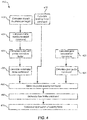
- method 400 may be configured to decelerate a manned and/or an autonomous aircraft during a landing phase, RTO event, and/or the like while also maintaining a steady course.
- method 400 may comprise calculating an aircraft deceleration target 104 (Step 402).
- Control mode executive 160 may calculate aircraft deceleration target 104 based on an input received from autonomous aircraft deceleration target 156 and/or pilot aircraft deceleration target input 158.
- Control mode executive 160 may transmit aircraft deceleration target 104 to autobrake controller 105.
- method 400 may comprise calculating an initial autobrake pedal command 112 (Step 404).
- Autobrake controller 105 may calculate the initial autobrake pedal command.
- the initial autobrake pedal command 112 may be based on aircraft deceleration target 104 and/or aircraft deceleration feedback 102.
- Autobrake controller 105 may transmit initial autobrake pedal command 112 to autobrake pedal executive 115.
- method 400 may comprise calculating an autobrake pedal correction factor 114 (Step 406).
- Pedal balance controller 110 may calculate autobrake pedal correction factor 114.
- Autobrake pedal correction factor 114 may be based on various environmental and/or operating factors, such as, for example, aircraft yaw angle 108, aircraft yaw speed 109, aircraft wheel speed, and/or other inputs 107.
- Pedal balance controller 110 may transmit autobrake pedal correction factor 114 to autobrake pedal executive 115.
- method 400 may comprise calculating an autobrake pedal command (Step 408) (e.g., autobrake pedal commands 117, 119).
- the autobrake pedal command may be calculated by autobrake pedal executive 115.
- autobrake pedal executive 115 may calculate an autobrake left pedal command 117 and/or an autobrake right pedal command 119.
- Each autobrake pedal command 117, 119 may be based on autobrake pedal correction factor 114 and initial autobrake pedal command 112.
- Autobrake pedal executive 115 may transmit each autobrake pedal command 117, 119 to pedal executive 120.
- method 400 may comprise calculating a braking force command 124 (Step 410).
- Control mode executive 160 may calculate braking force command 124 based on a pedal input braking signal received by autonomous pedal command 152 and/or pilot pedal input 154.
- Control mode executive 160 may transmit braking force command 124 to pedal executive 120.
- method 400 may comprise calculating a gear deceleration command (Step 422).
- Control mode executive 160 may calculate a gear deceleration command (e.g., left gear deceleration command 162 and/or right gear deceleration command 166) based on a pedal input braking signal received from autonomous pedal command 152 and/or pilot pedal input 154.
- a brake pedal in the aircraft may be deflected, and control mode executive 160 may receive a pilot pedal input 154 based on the amount of deflection (or an analogous pedal input braking signal may be received from autonomous pedal command 152).
- control mode executive 160 may calculate the gear deceleration command based on pilot pedal input 154 and/or autonomous pedal command 152.
- the gear deceleration command may comprise data indicating a desired deceleration rate for the aircraft.
- a gear deceleration command may comprise a gear deceleration command for one or more gears in braking assembly 60 (e.g., left gear deceleration command 162 for at least one gear on the left side of braking assembly 60, and right gear deceleration command 166 for at least one gear on the right side of braking assembly 60).
- control mode executive 160 may transmit the gear deceleration command to pedal deceleration controller 170, which may receive the gear deceleration commands.
- Pedal deceleration controller 170 may also receive gear deceleration feedback (e.g., left gear deceleration feedback 164 and/or right gear deceleration feedback 168) as described herein.
- Pedal deceleration controller 170 may calculate a gear pedal command (Step 424) (e.g., left gear pedal command 172 and/or right gear pedal command 174) based on the gear deceleration command and/or gear deceleration feedback.
- left gear pedal command 172 may be based on left gear deceleration command 162 and/or left gear deceleration feedback 164
- right gear pedal command 174 may be based on right gear deceleration command 166 and/or right gear deceleration feedback 168.
- pedal deceleration controller 170 may calculate left gear pedal command 172 based on the difference between the measured and desired deceleration rates to comprise data indicating that an additional 1.5 m/s 2 (4.92 ft/s 2 ) of deceleration is needed.
- Pedal deceleration controller 170 may transmit the gear pedal command to pedal executive 120, and pedal executive 120 may receive the gear pedal command.
- pedal deceleration controller 170 may adjust the gear pedal command transmitted to pedal executive 120 to correct such difference.
- method 400 may comprise generating a pedal braking command 122 (Step 450).
- Pedal executive 120 may be configured to generate pedal braking command 122.
- Pedal braking command 122 may be based on at least one of aircraft braking force command 124, the autobrake pedal commands, and/or gear pedal commands.
- Pedal executive 120 may receive the autobrake pedal commands (e.g., autobrake pedal commands 117, 119) from autobrake pedal executive 115.
- Pedal executive 120 may receive the braking force command 124 from control mode executive 160.
- Pedal executive 120 may receive the gear pedal commands (e.g., gear pedal commands 172, 174) from pedal deceleration controller 170.
- Pedal executive 120 may include a braking priority logic.
- the braking priority logic may dictate how to generate pedal braking command 122 in response to receiving the autobrake pedal commands, braking force command 124, and the gear pedal commands.
- pedal executive 120 may generate pedal braking command 122 based on braking force command 124, because braking priority logic may prioritize manual braking signals to automated braking signals.
- the braking priority logic of pedal executive 120 may prioritize between braking force command 124 (a force signal) and the gear pedal command (a deceleration signal) (both received from pedal input braking signals) depending on whether the aircraft comprising braking system 100 is traveling at a speed above or below a speed threshold (which may be any suitable speed, as described herein). For example, in response to an aircraft comprising braking system 100 traveling at a speed above a threshold speed, the braking priority logic may prioritize deceleration signals (e.g., gear pedal commands 172, 174) over force signals (e.g., braking force command 124).
- deceleration signals e.g., gear pedal commands 172, 174
- force signals e.g., braking force command 124
- pedal executive 120 may calculate pedal braking command 122 based on gear pedal commands 172, 174 to achieve a desired deceleration rate.
- the braking priority logic may prioritize force signals over deceleration signals. Therefore, at speeds below the threshold speed, pedal executive 120 may calculate pedal braking command 122 based on braking force command 124 to apply a braking force (e.g., pressure or current) to gears in braking assembly 60.
- Pedal executive 120 may transmit the pedal braking command to pedal braking controller 130.
- method 400 may comprise generating a final brake command 132 (Step 460).
- Pedal braking controller 130 may be configured to generate final brake command 132.
- Pedal braking controller 130 may receive pedal braking command 122 from pedal executive 120.
- Final brake command 132 may be based on at least one of the pedal braking command 122 and/or a braking feedback 131.
- Pedal braking controller 130 may comprise an antiskid controller (e.g., antiskid controller 54 of FIG. 3 ) configured to calculate an antiskid command 138.
- Final brake command 132 may also be based on the antiskid command 138.
- Pedal braking controller 130 may transmit and/or execute final brake command 132 on braking assembly 60, commanding braking assembly 60 to apply a braking force to gears and/or brakes based on pedal braking command 122 and/or final braking command 132 (step 470).
- pedal braking command 122 and/or final brake command 132 may cause braking assembly 60 to cause braking and/or deceleration in the aircraft.
- references to "various embodiments”, “one embodiment”, “an embodiment”, “an example embodiment”, etc. indicate that the embodiment described may include a particular feature, structure, or characteristic, but every embodiment may not necessarily include the particular feature, structure, or characteristic. Moreover, such phrases are not necessarily referring to the same embodiment. Further, when a particular feature, structure, or characteristic is described in connection with an embodiment, it is submitted that it is within the knowledge of one skilled in the art to affect such feature, structure, or characteristic in connection with other embodiments whether or not explicitly described. After reading the description, it will be apparent to one skilled in the relevant art(s) how to implement the disclosure in alternative embodiments.
Abstract
Description
- The present disclosure relates to aircraft braking systems, and more specifically, to braking systems comprising deceleration pedal control capabilities.
- Modern aircraft are typically equipped with a braking system. During a landing phase, taxiing, or a Rejected Take-Off ("RTO") event, for example, a pilot may engage a pedal to decrease the speed of the plane. Based on the deflection of the pedal by the pilot, the braking system may apply a pressure to one or more of the aircraft wheels through one or more brakes, slowing the plane.
- In various embodiments, an aircraft braking system is disclosed. In various embodiments, an aircraft braking system may comprise a control mode executive configured to receive a pedal input and calculate a gear deceleration command comprising a desired deceleration rate based on the pedal input; a pedal deceleration controller in electronic communication with the control mode executive configured to receive the gear deceleration command from the control mode executive and calculate a gear pedal command based on at least one of the gear deceleration command and a deceleration feedback; and a pedal executive in electronic communication with the pedal deceleration controller configured to receive the gear pedal command, and generate a pedal braking command based on the gear pedal command.
- In various embodiments, the aircraft braking system may further comprise a pedal braking controller in electronic communication with the pedal executive configured to calculate a final brake command, wherein the final brake command is based on at least one of the pedal braking command and a braking feedback. In various embodiments, the pedal executive may be configured to generate the pedal braking command based on the gear pedal command in response to an aircraft traveling at a high speed above a speed threshold. In various embodiments, the control mode executive may be configured to calculate a braking force command based on the pedal input. The pedal executive may be configured to receive the braking force command from the control mode executive and calculate the pedal braking command based on the braking force command in response to the aircraft traveling at a low speed below a speed threshold. In various embodiments, the pedal braking command may be configured to cause a brake assembly to exert a braking force on a gear.
- In various embodiments, the aircraft braking system may further comprise an autobrake controller in electronic communication with the control mode executive configured to receive an aircraft deceleration target from the control mode executive, and calculate an initial autobrake pedal command based on the aircraft deceleration target and an aircraft deceleration feedback. In various embodiments, the aircraft braking system may further comprise an autobrake pedal executive configured to receive the initial autobrake pedal command and calculate an autobrake pedal command based on the initial autobrake pedal command. In various embodiments, the aircraft braking system may further comprise a pedal balance controller configured to calculate an autobrake pedal correction factor based on at least one of an aircraft yaw angle, an aircraft yaw speed, and an aircraft wheel speed. The autobrake pedal executive may be configured to calculate the autobrake pedal command based on at least one of the initial autobrake pedal command or the autobrake pedal correction factor. In various embodiments, the pedal input may be received from at least one of a pedal brake in electronic communication with the control mode executive or an autonomous pedal command in electronic communication with the control mode executive.
- In various embodiments, a method of aircraft braking may comprise receiving, by a controller, a pedal input from at least one of a brake pedal or an autonomous pedal command; calculating, by the controller, a gear deceleration command comprising a desired deceleration rate; transmitting, by the controller, the gear deceleration command to a pedal deceleration controller; calculating, by the controller, a gear pedal command based on at least one of the gear deceleration command or a deceleration feedback; and generating, by the controller, a pedal braking command based on the gear pedal command. In various embodiments, the method may further comprise calculating, by the controller, a final brake command, wherein the final brake command is based on at least one of the pedal braking command or a braking feedback. In various embodiments, the method may further comprise commanding, by the controller, a braking assembly to apply a braking force to a gear based on the pedal braking command.
- In various embodiments, the pedal input may be associated with a deflection amount of the brake pedal. In various embodiments, the calculating the pedal braking command may be based on the gear pedal command in response to an aircraft traveling at a speed above a speed threshold. In various embodiments, the method may further comprise calculating, by the controller, a braking force command based on the pedal input, and wherein the calculating the pedal braking command may be based on the braking force command in response to an aircraft traveling at a speed below the speed threshold.
- In various embodiments, a tangible, non-transitory memory configured to communicate with a processor, the tangible, non-transitory memory having instructions stored thereon that, in response to execution by the processor, cause the processor to perform operations comprising receiving, by the processor, a pedal input from at least one of a brake pedal or an autonomous pedal command; calculating, by the processor, a gear deceleration command comprising a desired deceleration rate; calculating, by the processor, a gear pedal command based on at least one of the gear deceleration command or a deceleration feedback; and generating, by the processor, a pedal braking command based on the gear pedal command. In various embodiments, the operations may further comprise calculating, by the processor, a final brake command, wherein the final brake command may be based on at least one of the pedal braking command or a braking feedback. In various embodiments, the operations may further comprise commanding, by the processor, a braking assembly to apply a braking force to a gear in response to the generating the pedal braking command.
- In various embodiments, the pedal input may be associated with a deflection amount of the brake pedal. In various embodiments, the calculating the pedal braking command may be based on the gear pedal command in response to an aircraft traveling at a speed above a speed threshold. In various embodiments, the operations may further comprise calculating, by the processor, a braking force command based on the pedal input, and wherein the calculating the pedal braking command may be based on the braking force command in response to an aircraft traveling at a speed below the speed threshold.
- The subject matter of the present disclosure is particularly pointed out and distinctly claimed in the concluding portion of the specification. A more complete understanding of the present disclosure, however, may best be obtained by referring to the detailed description and claims when considered in connection with the following illustrative figures. In the following figures, like reference numbers refer to similar elements and steps throughout the figures.
-
FIG. 1 illustrates an exemplary aircraft, in accordance with various embodiments; -
FIG. 2 illustrates a schematic view of an aircraft braking system, in accordance with various embodiments; -
FIG. 3 illustrates a schematic view of a pedal braking controller for an aircraft braking system, in accordance with various embodiments; and -
FIG. 4 illustrates a method of aircraft braking, in accordance with various embodiments. - Elements and steps in the figures are illustrated for simplicity and clarity and have not necessarily been rendered according to any particular sequence. For example, steps that may be performed concurrently or in different order are illustrated in the figures to help to improve understanding of embodiments of the present disclosure.
- The detailed description of exemplary embodiments herein makes reference to the accompanying drawings, which show exemplary embodiments by way of illustration. While these exemplary embodiments are described in sufficient detail to enable those skilled in the art to practice the disclosures, it should be understood that other embodiments may be realized and that logical changes and adaptations in design and construction may be made in accordance with this disclosure and the teachings herein. Thus, the detailed description herein is presented for purposes of illustration only and not of limitation.
- The scope of the disclosure is defined by the appended claims and their legal equivalents rather than by merely the examples described. For example, the steps recited in any of the method or process descriptions may be executed in any order and are not necessarily limited to the order presented. Furthermore, any reference to singular includes plural embodiments, and any reference to more than one component or step may include a singular embodiment or step. Also, any reference to attached, fixed, coupled, connected or the like may include permanent, removable, temporary, partial, full and/or any other possible attachment option. Additionally, any reference to without contact (or similar phrases) may also include reduced contact or minimal contact. Surface shading lines may be used throughout the figures to denote different parts but not necessarily to denote the same or different materials.
- As used herein, "electronic communication" means communication of electronic signals with physical coupling (e.g., "electrical communication" or "electrically coupled") or without physical coupling and via an electromagnetic field (e.g., "inductive communication" or "inductively coupled" or "inductive coupling").
- In various embodiments, and with reference to
FIG. 1 , anexemplary aircraft 1 is depicted.Aircraft 1 may include landing gear such aslanding gear 12,landing gear 14, andlanding gear 16.Landing gear 12,landing gear 14, andlanding gear 16 may generally supportaircraft 1 whenaircraft 1 is not flying, allowingaircraft 1 to taxi, take off, and land without damage.Landing gear 12 may includewheel 13A andwheel 13B coupled by astrut 26;landing gear 14 may includewheel 15A andwheel 15B coupled by astrut 22; andlanding gear 16 may includenose wheel 17A andnose wheel 17B coupled by astrut 24.Wheel 13A andwheel 15A may be referred to as outboard wheels.Wheel 13B andwheel 15B may be referred to as inboard wheels.Nose wheels aircraft 1 may comprise any number of landing gears and each landing gear may comprise any number of wheels. -
Aircraft 1 may also include abraking assembly 60, which may be applied to any wheel of any landing gear.Braking assembly 60 may comprise thebrakes 19 of each landing gear (e.g.,landing gear 12,landing gear 14, and/or landing gear 16), and eachbrake 19 may be mounted to each wheel, and/or a gear coupled to each wheel, to apply and release braking force on one or more gears and/or wheels (e.g., as described herein). - Aircraft wheel and brake assemblies may typically include a non-rotatable wheel support, a wheel mounted to the wheel support for rotation, and a brake disk stack. The brake stack may also have alternating rotor and stator disks mounted with respect to the wheel support and wheel for relative axial movement. Each rotor disk may be coupled to the wheel for rotation therewith, and each stator disk may be coupled to the wheel support against rotation. A back plate may be located at the rear end of the disk stack and a brake head may be located at the front end. The brake head may house one or more actuator rams that extend to compress the brake disk stack against the back plate, or the brake disk stack may be compressed by other means. Torque is taken out by the stator disks through a static torque tube or the like. The actuator rams may be electrically operated actuator rams or hydraulically operated actuator rams, although in various embodiments, brakes may use pneumatically operated actuator rams.
- In brake systems that employ fluid powered (hydraulic or pneumatic power) actuator rams, the actuator ram may be coupled to a power source via a brake servo valve (BSV) and a shutoff valve (SOV). The SOV effectively functions as a shutoff valve, wherein in a first position (e.g., an armed position), fluid pressure is permitted to pass through the valve, while in a second position (e.g., a disarmed position) fluid pressure is restricted or prevented from passing through the valve. During normal braking, the SOV is in the armed position, thereby permitting the flow of fluid pressure. The BSV, based on braking commands from the pilot (often via an electronic controller that may implement, for example, anti-skid logic) controls the amount of fluid pressure provided to the actuator ram, and thus, the braking force applied to the gear and/or wheel. To prevent or minimize unintentional braking (e.g., due to a faulty servo valve) at various times, the SOV is set in the disarmed position, thereby removing or decreasing fluid pressure from the BSV. Since the BSV does not receive sufficient fluid pressure, it cannot provide fluid pressure to the actuator ram, and thus, braking cannot be effected.
- In electronic brakes, a brake controller (or controller) is coupled to one or more electromechanical actuator controllers (EMAC) for a brake, which drives one or more electromechanical brake actuators. The brake controller may be in communication with a brake pedal, and thus may control the EMAC in accordance with pilot/copilot braking commands. In various aircraft, other means are used to compress a brake disk stack. A brake controller may comprise a processor and a tangible, non-transitory memory. The brake controller may comprise one or more logic components that implement brake logic. In various embodiments, the brake controller may comprise other electrical devices to implement brake logic.
- In various embodiments, and with reference to
FIG. 2 , anaircraft braking system 100 is disclosed.Aircraft braking system 100 ofaircraft 1 may be one or more controllers comprising a collection of subsystems that produce output signals for controlling the braking force and/or torque applied by brakingassembly 60 at each wheel (e.g.,wheel 13A,wheel 13B,wheel 15A,wheel 15B,nose wheel 17A, and/ornose wheel 17B).Aircraft braking system 100 may be configured to control the deceleration of an aircraft (e.g.,aircraft 1 ofFIG. 1 ) during a deceleration event such as, for example, a landing phase, a RTO event, and/or the like, by transmitting afinal brake command 132 to brakingassembly 60. In that respect,aircraft braking system 100 may provide brake control capabilities for manual and autonomous braking of manned aircrafts (e.g., pilot commanded) and/or unmanned vehicles such as, for example, an unmanned aerial vehicle, an unmanned aerial system, and/or the like.Aircraft braking system 100 may be configured to decelerate the aircraft while maintaining a steady and/or desired course. For example, external factors such as wind, operating conditions of various components of the aircraft (e.g., imbalanced reverse thrusters, differing characteristics of individual braking systems, etc.), and/or the like may cause the aircraft to stray off a desired course of flight. In such conditions,aircraft braking system 100 may assist in maintaining the desired course of the aircraft during deceleration. The desired course may comprise, for example, a straight line, notwithstanding environmental factors such as wind and/or ground conditions. Furthermore,aircraft braking system 100 may be used to control, for example, two or more aircraft wheels (e.g.,wheel 13A,wheel 13B,wheel 15A,wheel 15B,nose wheel 17A, and/ornose wheel 17B ofFIG. 1 ).Aircraft braking system 100 may be configured to control a left side wheel and a right side wheel independently to allow for differential braking. Any number and configuration of wheels controlled byaircraft braking system 100 is within the scope of the present disclosure. - In various embodiments,
aircraft braking system 100 may comprise various software and/or hardware components, controllers, and/or the like. For example,aircraft braking system 100 may comprise anautobrake controller 105, apedal balance controller 110, an autobrakepedal executive 115, apedal executive 120, acontrol mode executive 160, apedal braking controller 130, and/or apedal deceleration controller 170. In various embodiments, brakingassembly 60, which is in communication withaircraft braking system 100, may comprise, for example, an electric, a hydraulic, or a hybrid electric-hydraulic braking assembly, as previously described.Aircraft braking system 100 may be configured to control braking force in an aircraft (e.g.,aircraft 1 ofFIG. 1 ) applied by brakingassembly 60. - In various embodiments,
aircraft braking system 100 may be comprised in an aircraft (e.g.,aircraft 1 inFIG. 1 ) and may be integrated into computer systems onboard the aircraft such as, for example, a brake control unit (BCU), a full authority digital engine control (FADEC), an engine-indicating and crew-alerting system (EICAS), and/or the like.Aircraft braking system 100 may also be a standalone computer system separate from the aircraft and in electronic communication with the aircraft, as described in further detail herein.Aircraft braking system 100 may include one or more processors and/or one or more tangible, non-transitory memories and be capable of implementing logic. As described herein, each subsystem, component, "controller", and/or the like may also comprise an individual processor and/or one or more tangible, non-transitory memories and be capable of implementing logic. In other embodiments, each subsystem, component, controller, and/or the like may also be implemented in a single processor (e.g.,aircraft braking system 100 may comprise a single processor). Each processor can be a general purpose processor, a digital signal processor (DSP), an application specific integrated circuit (ASIC), a field programmable gate array (FPGA) or other programmable logic device, discrete gate or transistor logic, discrete hardware components, or any combination thereof. - In various embodiments,
aircraft braking system 100, and/or each individual subsystem, component, and/or controller, may comprise a processor configured to implement various logical operations in response to execution of instructions, for example, instructions stored on a non-transitory, tangible, computer-readable medium. As used herein, the term "non-transitory" is to be understood to remove only propagating transitory signals per se from the claim scope and does not relinquish rights to all standard computer-readable media that are not only propagating transitory signals per se. - In various embodiments,
aircraft braking system 100 may comprise anautobrake controller 105.Autobrake controller 105 may be in electronic communication with autobrakepedal executive 115 and/orcontrol mode executive 160.Autobrake controller 105 may also be in electronic communication with various inputs, sensors, and/or the like, as discussed further herein.Autobrake controller 105 may be configured to calculate and/or transmit an initialautobrake pedal command 112.Autobrake controller 105 may calculate the initialautobrake pedal command 112 in response to receiving anaircraft deceleration target 104.Autobrake controller 105 may receive theaircraft deceleration target 104 from any suitable source, such as, for example, fromcontrol mode executive 160, as discussed further herein. Theaircraft deceleration target 104 may comprise data indicative of a desired deceleration rate for an aircraft. For example, theaircraft deceleration target 104 may comprise data indicating to decelerate the aircraft at a rate of about 1.0 m/s2 (3.28 ft/s2) to about 2.5 m/s2 (8.2 ft/s2), about 2.5 m/s2 (8.2 ft/s2) to about 3.5 m/s2 (11.48 ft/s2), about 3.5 m/s2 (11.48 ft/s2) to about 5.0 m/s2 (16.4 ft/s2), and/or any other suitable and/or desired deceleration rate (wherein about in this context refers only to +/- 1.0m/s2 (3.28 ft/s2)). - In various embodiments,
autobrake controller 105 may also be configured to receive anaircraft deceleration feedback 102.Aircraft deceleration feedback 102 may comprise data indicating the measured deceleration rate of the aircraft.Autobrake controller 105 may receiveaircraft deceleration feedback 102 from any suitable source. For example, the deceleration of the aircraft may be calculated and/or measured by a wheel speed sensor, a gyroscope sensor, a global positioning system (GPS), and/or any other suitable input, sensor, and/or the like capable of calculating the deceleration of the aircraft. -
Autobrake controller 105 may calculate the initialautobrake pedal command 112 based on theaircraft deceleration target 104 and/or theaircraft deceleration feedback 102. For example, in response to theaircraft deceleration feedback 102 comprising data indicating that the aircraft is decelerating at 1.0 m/s2 (3.28 ft/s2) and theaircraft deceleration target 104 comprising data indicating that the target or desired deceleration rate is 2.5 m/s2 (8.2 ft/s2),autobrake controller 105 may calculate the initialautobrake pedal command 112 to comprise data indicating that an additional 1.5 m/s2 (4.92 ft/s2) of deceleration is needed.Autobrake controller 105 may transmit the initialautobrake pedal command 112 to autobrakepedal executive 115. - In various embodiments,
aircraft braking system 100 may comprise apedal balance controller 110.Pedal balance controller 110 may be in electronic communication with autobrakepedal executive 115.Pedal balance controller 110 may also be in electronic communication with various inputs, sensors, and/or the like, as discussed further herein.Pedal balance controller 110 may be configured to calculate and/or transmit an autobrakepedal correction factor 114. In various embodiments,pedal balance controller 110 may be configured to calculate a single autobrakepedal correction factor 114 or multiple autobrake pedal correction factors 114 (e.g.,pedal balance controller 110 may calculate a separate autobrake pedal correction factor for a left pedal and a right pedal, and/or the like). Autobrakepedal correction factor 114 may comprise data indicating various environmental and operating conditions of the aircraft. For example,pedal balance controller 110 may receive data relating to environmental and/or operating conditions, such as anaircraft yaw angle 108, anaircraft yaw speed 109, and/or other inputs 107 (e.g., aircraft wheel speed).Pedal balance controller 110 may receive the data from any suitable input, sensor, and/or the like. The autobrakepedal correction factor 114 may be based on at least one of theaircraft yaw angle 108, theaircraft yaw speed 109, and/or theother inputs 107. In that respect, the autobrakepedal correction factor 114 may be used to modify initialautobrake pedal command 112 to accommodate for measured environmental and/or operating conditions and assist in maintaining a desired course of the aircraft.Pedal balance controller 110 may transmit the autobrakepedal correction factor 114 to autobrakepedal executive 115. - In various embodiments,
aircraft braking system 100 may comprise an autobrakepedal executive 115. Autobrakepedal executive 115 may be in electronic communication withautobrake controller 105,pedal balance controller 110, and/orpedal executive 120. Autobrakepedal executive 115 may be configured to receive the initialautobrake pedal command 112 and/or the autobrakepedal correction factor 114. Autobrakepedal executive 115 may receive the initialautobrake pedal command 112 fromautobrake controller 105. Autobrakepedal executive 115 may receive the autobrakepedal correction factor 114 frompedal balance controller 110. Autobrakepedal executive 115 may be configured to calculate one or more individual pedal braking commands. For example, autobrakepedal executive 115 may be configured to calculate an autobrake left pedal command 117 (associated with a left brake pedal and brakes) and/or an autobrake right pedal command 119 (associated with a left brake pedal and brakes). Eachautobrake pedal command autobrake pedal command 112 and/or the autobrakepedal correction factor 114. In that respect, each autobrakepedal command pedal executive 115 may transmit each autobrakepedal command pedal executive 120. - In various embodiments,
aircraft braking system 100 may comprise acontrol mode executive 160.Control mode executive 160 may be in electronic communication withautobrake controller 105,pedal deceleration controller 170, and/orpedal executive 120.Control mode executive 160 may also be configured to receive inputs from various sources. For example,control mode executive 160 may be in logical and/or electronic communication with anautonomous pedal command 152, apilot pedal input 154, an autonomousaircraft deceleration target 156, and/or a pilot aircraftdeceleration target input 158. In that respect,control mode executive 160 may be configured as a central hub to receive and transmit braking signals such as deceleration signals (expressed in a deceleration rate) and/or force signals (expressed in a braking force, such as a pressure).Control mode executive 160 may allow for both manual inputs (e.g., viapilot pedal input 154 and/or pilot aircraft deceleration target input 158) and autonomous inputs (e.g., viaautonomous pedal command 152 and/or autonomous aircraft deceleration target 156). In that regard,control mode executive 160 may be configured to allow manual deceleration input and/or braking control and autonomous deceleration input and/or braking control toaircraft braking system 100.Autonomous pedal command 152 and/orpilot pedal input 154 may be referred to as "pedal inputs," as both provide braking signals associated with a brake pedal. - In various embodiments,
pilot pedal input 154 may be configured to allow manual input of braking signals. For example,pilot pedal input 154 may be located in the aircraft cockpit, and may comprise a physical brake pedal allowing a pilot and/or copilot to depress or deflect the pedals to input a braking signal (i.e., a pedal input). It should be understood thatpilot pedal input 154 may provide a braking signal from one or more brake pedals (i.e., a left pedal brake provides left pedal inputs and a right pedal brake provides right pedal inputs). Based on the angle or displacement of the pedals,control mode executive 160 may calculate a corresponding braking force (e.g., a pressure or current) and/or deceleration rate for each corresponding pedal to transmit topedal executive 120. - In various embodiments,
autonomous pedal command 152 may be configured to allow automated and/or remote input of braking signals (i.e., pedal inputs). For example,autonomous pedal command 152 may be located onboard or external the aircraft and may comprise preprogrammed data comprising braking signals to transmit (e.g., during a preprogrammed flight, the aircraft, viaautonomous pedal command 152, may be configured to brake at a predefined time, location, and/or the like).Autonomous pedal command 152 may also be configured to receive remote braking signals, such as, for example, during a remote control of the aircraft. It should be understood that the braking signal received fromautonomous pedal command 152 may be an analogous braking signal received from apilot pedal input 154, but without physical deflection of a brake pedal. - In various embodiments,
control mode executive 160 may be configured to calculate abraking force command 124 based on input received from at least one ofautonomous pedal command 152 andpilot pedal input 154. The brakingforce command 124 may comprise a single braking signal or multiple braking signals (e.g., the brakingforce command 124 may comprise a separate braking command for a right pedal and a left pedal, and/or the like). The brakingforce command 124 may comprise data indicating a braking force (e.g., a pressure) to apply to each gear and/or brake inbraking assembly 60.Control mode executive 160 may transmit thebraking force command 124 topedal executive 120. - In various embodiments,
control mode executive 160 may be configured to calculate a leftgear deceleration command 162 and a rightgear deceleration command 166 based on input received from at least one ofautonomous pedal command 152 andpilot pedal input 154. Gear deceleration commands 162, 166 may comprise data indicating a desired deceleration rate to achieve for each gear inbraking assembly 60. For example, the gear deceleration commands 162, 166 may comprise data indicating to decelerate the aircraft at a rate of about 1.0 m/s2 (3.28 ft/s2) to about 2.5 m/s2 (8.2 ft/s2), about 2.5 m/s2 (8.2 ft/s2) to about 3.5 m/s2 (11.48 ft/s2), about 3.5 m/s2 (11.48 ft/s2) to about 5.0 m/s2 (16.4 ft/s2), and/or any other suitable and/or desired deceleration rate (wherein about in this context refers only to +/- 1.0 m/s2 (3.28 ft/s2)). -
Control mode executive 160 may calculate leftgear deceleration command 162 based on a left pedal input of pilot pedal input 154 (e.g., a deflection amount of a left brake pedal or a left pedal command from autonomous pedal command 152), and may calculate rightgear deceleration command 166 based on a right pedal input of pilot pedal input 154 (e.g., a deflection amount of a right brake pedal or a right pedal command from autonomous pedal command 152). Leftgear deceleration command 162 may indicate a desired deceleration rate for a left gear inbraking assembly 60, and rightgear deceleration command 166 may indicate a desired deceleration rate for a right gear inbraking assembly 60. - In operation, for example, a pilot may wish to slow an aircraft, wherein the deceleration rates available from braking
system 100 by deflecting the brake pedal(s) may be between about 1.0 m/s2 (3.28 ft/s2) and about 5.0 m/s2 (16.4 ft/s2), or between about 2.5 m/s2 (8.2 ft/s2) about 3.5 m/s2 (11.48 ft/s2), or any other suitable and/or desired deceleration rate (wherein "about" in this context refers only to +/- 1.0 m/s2 (3.28 ft/s2)). In response to the right brake pedal being deflected,control mode executive 160 may calculate a rightgear deceleration command 166 comprising a desired deceleration rate based on the deflection amount of the right brake pedal. In response to the left brake pedal being deflected,control mode executive 160 may calculate a leftgear deceleration command 162 comprising a desired deceleration rate based on the deflection amount of the left brake pedal.Control mode executive 160 may transmit gear deceleration commands 162, 166 topedal deceleration controller 170. - In various embodiments,
pedal deceleration controller 170 may comprise one controller or multiple controllers (e.g., one controller for a left gear ofbraking assembly 60 and one controller for a right gear of braking assembly 60).Pedal deceleration controller 170 may be in electronic or logical communication withcontrol mode executive 160 and/orpedal executive 120.Pedal deceleration controller 170 may also be in electronic communication with various inputs, sensors, and/or the like, as discussed further herein.Pedal deceleration controller 170 may be configured to calculate and/or transmit a gear pedal command (e.g., a leftgear pedal command 172 and/or a right gear pedal command 174) topedal executive 120.Pedal deceleration controller 170 may calculate leftgear pedal command 172 in response to receiving leftgear deceleration command 162, andpedal deceleration controller 170 may calculate rightgear pedal command 174 in response to receiving rightgear deceleration command 166.Pedal deceleration controller 170 may receive gear deceleration commands 162, 166 from any suitable source, such as, for example, fromcontrol mode executive 160. - In various embodiments,
pedal deceleration controller 170 may also be configured to receive agear deceleration feedback Gear deceleration feedback gear deceleration feedback 164 may indicate the measured deceleration of a gear in the left side ofbraking assembly 60, and rightgear deceleration feedback 168 may indicate the measured deceleration rate of a gear in the right side of braking assembly 60).Pedal deceleration controller 170 may receivegear deceleration feedback -
Pedal deceleration controller 170 may calculate the gear pedal commands 172, 174 based on gear deceleration commands 162, 166 and/or thegear deceleration feedback gear deceleration feedback 164 comprising data indicating that the aircraft has a measured deceleration rate of 1.0 m/s2 (3.28 ft/s2) and leftgear deceleration command 162 comprising data indicating that the desired deceleration rate is 2.5 m/s2 (8.2 ft/s2),pedal deceleration controller 170 may calculate leftgear pedal command 172 based on the difference between the measured and desired deceleration rates to comprise data indicating an adjusted deceleration rate (e.g., that an additional 1.5 m/s2 (4.92 ft/s2) of deceleration is needed).Pedal deceleration controller 170 may transmit gear pedal commands 172, 174 topedal executive 120. - In various embodiments, pilot aircraft
deceleration target input 158 may be configured to allow manual input of deceleration signals. For example, pilot aircraftdeceleration target input 158 may be located in the aircraft cockpit, and/or in any other suitable location onboard the aircraft. A pilot, copilot, and/or any other suitable user may select a desired deceleration, such as, for example, "low", "medium", "max", "RTO", and/or the like. Each selected deceleration may correspond to a deceleration speed (e.g., "low" may correspond to 1.0 m/s2 (3.28 ft/s2), "medium" may correspond to 2.5 m/s2 (8.2 ft/s2), "max" may correspond to 3.5 m/s2 (11.5 ft/s2), "RTO" may correspond to 5.0 m/s2 (16.4 ft/s2), etc.). Pilot aircraftdeceleration target input 158 may transmit the selected deceleration to controlmode executive 160. - In various embodiments, autonomous
aircraft deceleration target 156 may be configured to allow automated and/or remote input of deceleration signals. For example, autonomousaircraft deceleration target 156 may be located onboard or external the aircraft and may include preprogrammed data comprising deceleration signals to transmit (e.g., during an autonomous flight, the aircraft, via autonomousaircraft deceleration target 156, may be configured to decelerate at a predefined time, location, and/or the like). Autonomousaircraft deceleration target 156 may also be configured to receive remote deceleration signals, such as, for example, during a remote control of the aircraft, and transmit the remote deceleration signals to controlmode executive 160.Control mode executive 160 may calculateaircraft deceleration target 104 based on autonomousaircraft deceleration target 156 and/or pilot aircraftdeceleration target input 158. - In various embodiments,
control mode executive 160 may also comprise a priority logic (e.g., force signal priority logic and/or deceleration signal priority logic). For example, in response to receiving input from bothautonomous pedal command 152 and pilot pedal input 154 (e.g., receiving both manual and autonomous pedal input braking signals),control mode executive 160 may give priority to the manual input (e.g., pilot pedal input 154) and transmit thebraking force command 124, and/or gear deceleration commands 162, 166, based on that braking signal. As a further example, in response to receiving input from both autonomousaircraft deceleration target 156 and pilot aircraft deceleration target input 158 (e.g., receiving both manual and autonomous deceleration signals),control mode executive 160 may give priority to the manual input (e.g., pilot aircraft deceleration target input 158) and transmit theaircraft deceleration target 104 based on that deceleration signal. In various embodiments,control mode executive 160 may provide priority based on any suitable and/or desired priority configuration. - In various embodiments,
aircraft braking system 100 may comprise apedal executive 120.Pedal executive 120 may be in electronic communication with autobrakepedal executive 115,control mode executive 160, and/orpedal deceleration controller 170.Pedal executive 120 may be configured to receive various braking commands. For example,pedal executive 120 may be configured to receive autobrakeleft pedal command 117, autobrakeright pedal command 119, brakingforce command 124, leftgear pedal command 172, and/or rightgear pedal command 174.Pedal executive 120 may receive the autobrake leftpedal command 117 and/or the autobrake rightpedal command 119 from autobrakepedal executive 115.Pedal executive 120 may receive thebraking force command 124 fromcontrol mode executive 160.Pedal executive 120 may receive leftgear pedal command 172 and rightgear pedal command 174 frompedal deceleration controller 170. - In various embodiments,
pedal executive 120 may also be configured to generate apedal braking command 122. Thepedal braking command 122 may comprise data relating to a desired braking force (e.g., a pressure) to be applied inbraking assembly 60. In that respect, thepedal braking command 122 may be based on at least one ofbraking force command 124, autobrake pedal commands 117, 119, and/or gear pedal commands 172, 174.Pedal executive 120 may receivebraking force command 124, autobrake pedal commands 117, 119, and/or gear pedal commands 172, 174, analyze each command to determine the braking force to apply to each brake inbraking assembly 60, and generate thepedal braking command 122 to comprise data indicating that corresponding braking force. For example, wherein brakingassembly 60 comprises a hydraulic braking system, thepedal braking command 122 may comprise a fluid braking pressure (e.g., 200 psi (1379 kPa), 300 psi (2068 kPa), etc.). Therefore,pedal executive 120 may convert deceleration signals (e.g., gear pedal commands 172, 174 and/or autobrake pedal commands 117, 119) into pressure values. Where brakingassembly 60 comprises an electronic braking system, thepedal braking command 122 may comprise an electronic braking force.Pedal executive 120 may be configured to transmit thepedal braking command 122 topedal braking controller 130.Pedal braking command 122 may comprise one or more commands (e.g., a left command for left gears/brakes ofbraking assembly 60, and a right command for right gears/brakes of braking assembly 60). Therefore,pedal executive 120 may convert deceleration signals (e.g., gear pedal commands 172, 174 and/or autobrake pedal commands 117, 119) into current values to be drawn by an electromechanical actuator. - In various embodiments,
pedal executive 120 may also include a braking priority logic. For example,pedal executive 120 may give priority to received force signals (e.g., the braking force command 124) over received deceleration signals (e.g., the autobrake leftpedal command 117 and/or the autobrake right pedal command 119). In that respect, in response to receiving both thebraking force command 124 and the autobrake leftpedal command 117 and/or the autobrake rightpedal command 119,pedal executive 120 may generate thepedal braking command 122 to comprise data corresponding to thebraking force command 124. In various embodiments, the braking priority logic ofpedal executive 120 may give priority to received deceleration signals over received force signals. - In various embodiments, the braking priority logic of
pedal executive 120 may prioritize different signal types (e.g., force signals vs. deceleration signals) depending on the speed at which an aircraft is traveling. For example, in response to an aircraft comprisingbraking system 100 traveling at a speed above a threshold speed, the braking priority logic may prioritize deceleration signals (e.g., gear pedal commands 172, 174) over force signals (e.g., braking force command 124). Therefore, at speeds above the threshold speed, in response to receiving pedal input braking signals fromautonomous pedal command 152 and/orpilot pedal input 154,pedal executive 120 may calculatepedal braking command 122 based on gear pedal commands 172, 174 to achieve a desired deceleration rate. At low speed, such as speeds below the speed threshold, commands to slow the aircraft should be processed and executed rapidly. Because brakingforce command 124 may be processed more rapidly than deceleration signals (because deceleration signals must be converted into force values (e.g., pressures or current) by pedal executive 120), at speeds below the speed threshold, force signals may be prioritized. Therefore, in response to an aircraft comprisingbraking system 100 traveling at a speed below the threshold speed, in response to receiving pedal input braking signals fromautonomous pedal command 152 and/orpilot pedal input 154, the braking priority logic may prioritize force signals over deceleration signals. Therefore, at speeds below the threshold speed, in response to receiving pedal input braking signals fromautonomous pedal command 152 and/orpilot pedal input 154,pedal executive 120 may calculatepedal braking command 122 based on brakingforce command 124 to apply a braking force (e.g., pressure or current) to gears inbraking assembly 60. - In various embodiments, the speed threshold may be any suitable speed such as 30 knots (56 kilometers per hour (kmh); 35 miles per hour (mph)), or 40 knots (74 kmh; 46 mph).
- In various embodiments,
aircraft braking system 100 may comprise apedal braking controller 130.Pedal braking controller 130 may be in electronic communication withpedal executive 120 and/orbraking assembly 60.Pedal braking controller 130 may comprise various components, subsystems, and/or the like. In that respect, and with reference toFIG. 3 ,pedal braking controller 130 may comprise a brakepedal command controller 52, anantiskid controller 54, and/or a brakecontrol algorithm executive 56. In various embodiments, there may be more than onepedal braking controller 130. For example, there may be onepedal braking controller 130 for gears on the left side ofbraking assembly 60, and onepedal braking controller 130 for gears on the right side ofbraking assembly 60 - In various embodiments, with combined reference to
FIGS. 2 and3 , brakepedal command controller 52 may be in electronic and/or logical communication with brakecontrol algorithm executive 56 and/orpedal executive 120. Brakepedal command controller 52 may also be in electronic communication with various inputs, sensors, and/or the like, as described further herein. Brakepedal command controller 52 may be configured to receive thepedal braking command 122 frompedal executive 120. Brakepedal command controller 52 may also receive abraking feedback 131. Thebraking feedback 131 may comprise data indicating the braking force (e.g., pressure or current) being applied by brakingassembly 60. In various embodiments, thebraking feedback 131 may comprise data indicating the braking force (e.g., pressure or current) being applied to each brake ofaircraft 1. In further embodiments, thebraking feedback 131 may comprise data indicating the braking force (e.g., pressure or current) being applied to multiple brakes ofaircraft 1. Brakepedal command controller 52 may be configured to calculate abrake command 136. Brakepedal command controller 52 may calculate thebrake command 136 based on thepedal braking command 122 and thebraking feedback 131. For example, when thepedal braking command 122 comprises 1000 psi (6895 kPa), and thebraking feedback 131 comprises 800 psi (5516 kPa), brakepedal command controller 52 may generate thebrake command 136 to comprise an additional 200 psi (1379 kPa) (e.g., to increase the current braking pressure in the aircraft to match the desired braking pressure). Brakepedal command controller 52 may transmit thebrake command 136 to brakecontrol algorithm executive 56. - In various embodiments,
antiskid controller 54 may be in electronic and/or logical communication with brakecontrol algorithm executive 56.Antiskid controller 54 may also be in electronic communication with various inputs, sensors, and/or the like, as discussed further herein. For example,antiskid controller 54 may be configured to receive awheel speed feedback 134. Thewheel speed feedback 134 may be measured by a wheel sensor, and/or the like, and may comprise data indicating the current speed of each wheel in the aircraft.Antiskid controller 54 may analyze thewheel speed feedback 134 and calculate anantiskid command 138. Theantiskid command 138 may comprise data indicating a maximum brake pressure and/or force that should be applied to each aircraft wheel. For example, in response to thewheel speed feedback 134 comprising data indicating that a wheel is locking up,antiskid controller 54 may calculate theantiskid command 138 to indicate that no additional braking force and/or pressure should be applied to that corresponding wheel, or that only a maximum of 500 psi (3447 kPa), and/or any other suitable calculated value, should be allowed to that corresponding wheel.Antiskid controller 54 may transmit theantiskid command 138 to brakecontrol algorithm executive 56. - In various embodiments, with continued reference to
FIGS. 2 and3 , brakecontrol algorithm executive 56 may be in electronic and/or logical communication with brakepedal command controller 52 and/orantiskid controller 54. Brakecontrol algorithm executive 56 may also be in electronic communication withbraking assembly 60. Brakecontrol algorithm executive 56 may be configured to receive thebrake command 136. Brakecontrol algorithm executive 56 may also be configured to receive theantiskid command 138 fromantiskid controller 54. With combined reference toFIGS. 2 and3 , brakecontrol algorithm executive 56 may be configured to calculate afinal brake command 132. The final braking command may be based on thebrake command 136 and theantiskid command 138. For example, in response to thebrake command 136 having a braking pressure of 1200 psi (8274 kPa) and theantiskid command 138 comprising a maximum braking pressure of 800 psi (5516 kPa), brakecontrol algorithm executive 56 may generate thefinal brake command 132 to comprise data indicating a braking pressure of 800 psi (5516 kPa). Brakecontrol algorithm executive 56 may transmit thefinal brake command 132 to brakingassembly 60.Braking assembly 60 may receive thefinal brake command 132 and may apply braking force and/or pressure to each corresponding aircraft wheel brake to achieve the force and/or pressure commanded by thefinal brake command 132. - In various embodiments, and with reference to
FIG. 4 , amethod 400 of aircraft braking is illustrated. As previously discussed, and in various embodiments,method 400 may be configured to decelerate a manned and/or an autonomous aircraft during a landing phase, RTO event, and/or the like while also maintaining a steady course. In various embodiments, with combined reference toFIGS. 2 and4 ,method 400 may comprise calculating an aircraft deceleration target 104 (Step 402).Control mode executive 160 may calculateaircraft deceleration target 104 based on an input received from autonomousaircraft deceleration target 156 and/or pilot aircraftdeceleration target input 158.Control mode executive 160 may transmitaircraft deceleration target 104 toautobrake controller 105. In various embodiments,method 400 may comprise calculating an initial autobrake pedal command 112 (Step 404).Autobrake controller 105 may calculate the initial autobrake pedal command. The initialautobrake pedal command 112 may be based onaircraft deceleration target 104 and/oraircraft deceleration feedback 102.Autobrake controller 105 may transmit initialautobrake pedal command 112 to autobrakepedal executive 115. - In various embodiments,
method 400 may comprise calculating an autobrake pedal correction factor 114 (Step 406).Pedal balance controller 110 may calculate autobrakepedal correction factor 114. Autobrakepedal correction factor 114 may be based on various environmental and/or operating factors, such as, for example,aircraft yaw angle 108,aircraft yaw speed 109, aircraft wheel speed, and/orother inputs 107.Pedal balance controller 110 may transmit autobrakepedal correction factor 114 to autobrakepedal executive 115. - In various embodiments,
method 400 may comprise calculating an autobrake pedal command (Step 408) (e.g., autobrake pedal commands 117, 119). The autobrake pedal command may be calculated by autobrakepedal executive 115. For example, autobrakepedal executive 115 may calculate an autobrakeleft pedal command 117 and/or an autobrakeright pedal command 119. Eachautobrake pedal command pedal correction factor 114 and initialautobrake pedal command 112. Autobrakepedal executive 115 may transmit each autobrakepedal command pedal executive 120. - In various embodiments,
method 400 may comprise calculating a braking force command 124 (Step 410).Control mode executive 160 may calculate brakingforce command 124 based on a pedal input braking signal received byautonomous pedal command 152 and/orpilot pedal input 154.Control mode executive 160 may transmit brakingforce command 124 topedal executive 120. - In various embodiments, with continued reference to
FIGS. 2 and4 ,method 400 may comprise calculating a gear deceleration command (Step 422).Control mode executive 160 may calculate a gear deceleration command (e.g., leftgear deceleration command 162 and/or right gear deceleration command 166) based on a pedal input braking signal received fromautonomous pedal command 152 and/orpilot pedal input 154. As discussed herein, a brake pedal in the aircraft may be deflected, andcontrol mode executive 160 may receive apilot pedal input 154 based on the amount of deflection (or an analogous pedal input braking signal may be received from autonomous pedal command 152). In response,control mode executive 160 may calculate the gear deceleration command based onpilot pedal input 154 and/orautonomous pedal command 152. The gear deceleration command may comprise data indicating a desired deceleration rate for the aircraft. A gear deceleration command may comprise a gear deceleration command for one or more gears in braking assembly 60 (e.g., leftgear deceleration command 162 for at least one gear on the left side ofbraking assembly 60, and rightgear deceleration command 166 for at least one gear on the right side of braking assembly 60). - In various embodiments,
control mode executive 160 may transmit the gear deceleration command topedal deceleration controller 170, which may receive the gear deceleration commands.Pedal deceleration controller 170 may also receive gear deceleration feedback (e.g., leftgear deceleration feedback 164 and/or right gear deceleration feedback 168) as described herein.Pedal deceleration controller 170 may calculate a gear pedal command (Step 424) (e.g., leftgear pedal command 172 and/or right gear pedal command 174) based on the gear deceleration command and/or gear deceleration feedback. For example, leftgear pedal command 172 may be based on leftgear deceleration command 162 and/or leftgear deceleration feedback 164, and rightgear pedal command 174 may be based on rightgear deceleration command 166 and/or rightgear deceleration feedback 168. For example, in response to leftgear deceleration feedback 164 comprising data indicating that the aircraft is decelerating at 1.0 m/s2 (3.28 ft/s2) and leftgear deceleration command 162 comprising data indicating that the desired deceleration rate is 2.5 m/s2 (8.2 ft/s2),pedal deceleration controller 170 may calculate leftgear pedal command 172 based on the difference between the measured and desired deceleration rates to comprise data indicating that an additional 1.5 m/s2 (4.92 ft/s2) of deceleration is needed.Pedal deceleration controller 170 may transmit the gear pedal command topedal executive 120, andpedal executive 120 may receive the gear pedal command. In response to the measured deceleration rate of the aircraft (reflected in gear deceleration feedback) and the desired deceleration rate (reflected in the gear deceleration command) differing,pedal deceleration controller 170 may adjust the gear pedal command transmitted topedal executive 120 to correct such difference. - In various embodiments,
method 400 may comprise generating a pedal braking command 122 (Step 450).Pedal executive 120 may be configured to generatepedal braking command 122.Pedal braking command 122 may be based on at least one of aircraftbraking force command 124, the autobrake pedal commands, and/or gear pedal commands.Pedal executive 120 may receive the autobrake pedal commands (e.g., autobrake pedal commands 117, 119) from autobrakepedal executive 115.Pedal executive 120 may receive thebraking force command 124 fromcontrol mode executive 160.Pedal executive 120 may receive the gear pedal commands (e.g., gear pedal commands 172, 174) frompedal deceleration controller 170. -
Pedal executive 120 may include a braking priority logic. For example, the braking priority logic may dictate how to generatepedal braking command 122 in response to receiving the autobrake pedal commands, brakingforce command 124, and the gear pedal commands. For example, in response to receiving both thebraking force command 124 and the autobrake pedal command,pedal executive 120 may generatepedal braking command 122 based on brakingforce command 124, because braking priority logic may prioritize manual braking signals to automated braking signals. - In various embodiments, the braking priority logic of
pedal executive 120 may prioritize between braking force command 124 (a force signal) and the gear pedal command (a deceleration signal) (both received from pedal input braking signals) depending on whether the aircraft comprisingbraking system 100 is traveling at a speed above or below a speed threshold (which may be any suitable speed, as described herein). For example, in response to an aircraft comprisingbraking system 100 traveling at a speed above a threshold speed, the braking priority logic may prioritize deceleration signals (e.g., gear pedal commands 172, 174) over force signals (e.g., braking force command 124). Therefore, at speeds above the threshold speed,pedal executive 120 may calculatepedal braking command 122 based on gear pedal commands 172, 174 to achieve a desired deceleration rate. In response to an aircraft comprisingbraking system 100 traveling at a speed below the threshold speed, the braking priority logic may prioritize force signals over deceleration signals. Therefore, at speeds below the threshold speed,pedal executive 120 may calculatepedal braking command 122 based on brakingforce command 124 to apply a braking force (e.g., pressure or current) to gears inbraking assembly 60.Pedal executive 120 may transmit the pedal braking command to pedal brakingcontroller 130. - In various embodiments,
method 400 may comprise generating a final brake command 132 (Step 460).Pedal braking controller 130 may be configured to generatefinal brake command 132.Pedal braking controller 130 may receivepedal braking command 122 frompedal executive 120.Final brake command 132 may be based on at least one of thepedal braking command 122 and/or abraking feedback 131.Pedal braking controller 130 may comprise an antiskid controller (e.g.,antiskid controller 54 ofFIG. 3 ) configured to calculate anantiskid command 138.Final brake command 132 may also be based on theantiskid command 138.Pedal braking controller 130 may transmit and/or executefinal brake command 132 on brakingassembly 60, commandingbraking assembly 60 to apply a braking force to gears and/or brakes based onpedal braking command 122 and/or final braking command 132 (step 470). In that regard,pedal braking command 122 and/orfinal brake command 132 may causebraking assembly 60 to cause braking and/or deceleration in the aircraft. - Benefits, other advantages, and solutions to problems have been described herein with regard to specific embodiments. Furthermore, the connecting lines shown in the various figures contained herein are intended to represent exemplary functional relationships and/or physical couplings between the various elements. It should be noted that many alternative or additional functional relationships or physical connections may be present in a practical system. However, the benefits, advantages, solutions to problems, and any elements that may cause any benefit, advantage, or solution to occur or become more pronounced are not to be construed as critical, required, or essential features or elements of the disclosures. The scope of the disclosures is accordingly to be limited by nothing other than the appended claims and their legal equivalents, in which reference to an element in the singular is not intended to mean "one and only one" unless explicitly so stated, but rather "one or more." Moreover, where a phrase similar to "at least one of A, B, and C" is used in the claims, it is intended that the phrase be interpreted to mean that A alone may be present in an embodiment, B alone may be present in an embodiment, C alone may be present in an embodiment, or that any combination of the elements A, B and C may be present in a single embodiment; for example, A and B, A and C, B and C, or A and B and C.
- Systems, methods and apparatus are provided herein. In the detailed description herein, references to "various embodiments", "one embodiment", "an embodiment", "an example embodiment", etc., indicate that the embodiment described may include a particular feature, structure, or characteristic, but every embodiment may not necessarily include the particular feature, structure, or characteristic. Moreover, such phrases are not necessarily referring to the same embodiment. Further, when a particular feature, structure, or characteristic is described in connection with an embodiment, it is submitted that it is within the knowledge of one skilled in the art to affect such feature, structure, or characteristic in connection with other embodiments whether or not explicitly described. After reading the description, it will be apparent to one skilled in the relevant art(s) how to implement the disclosure in alternative embodiments.
- Furthermore, no element, component, or method step in the present disclosure is intended to be dedicated to the public regardless of whether the element, component, or method step is explicitly recited in the claims. As used herein, the terms "comprises", "comprising", or any other variation thereof, are intended to cover a non-exclusive inclusion, such that a process, method, article, or apparatus that comprises a list of elements does not include only those elements but may include other elements not expressly listed or inherent to such process, method, article, or apparatus.
Claims (15)
- An aircraft braking system, comprising:a control mode executive (160) configured to receive a pedal input and calculate a gear deceleration command comprising a desired deceleration rate based on the pedal input;a pedal deceleration controller (170) in electronic communication with the control mode executive (160) configured to receive the gear deceleration command from the control mode executive (160) and calculate a gear pedal command based on at least one of the gear deceleration command and a deceleration feedback, wherein the gear pedal command comprises a gear deceleration rate; anda pedal executive (120) in electronic communication with the pedal deceleration controller (170) configured to receive the gear pedal command, and generate a pedal braking command based on the gear pedal command.
- The aircraft braking system of claim 1, further comprising a pedal braking controller (130) in electronic communication with the pedal executive (120) configured to calculate a final brake command, wherein the final brake command is based on at least one of the pedal braking command and a braking feedback.
- The aircraft braking system of claims 1 or 2, wherein the pedal executive (120) is configured to generate the pedal braking command based on the gear pedal command in response to an aircraft traveling at a high speed above a speed threshold, and
wherein the control mode executive (160) is configured to calculate a braking force command based on the pedal input, wherein the pedal executive (120) is configured to receive the braking force command from the control mode executive (160) and calculate the pedal braking command based on the braking force command in response to the aircraft traveling at a low speed below a speed threshold. - The aircraft braking system of any preceding claim, wherein the pedal braking command is configured to cause a brake assembly to exert a braking force on a gear.
- The aircraft braking system of any preceding claim, further comprising an autobrake controller (105) in electronic communication with the control mode executive configured to receive an aircraft deceleration target from the control mode executive, and calculate an initial autobrake pedal command based on the aircraft deceleration target and an aircraft deceleration feedback, and preferably
further comprising an autobrake pedal executive (115) configured to receive the initial autobrake pedal command and calculate an autobrake pedal command based on the initial autobrake pedal command, and more preferably further comprising a pedal balance controller configured to calculate an autobrake pedal correction factor based on at least one of an aircraft yaw angle, an aircraft yaw speed, and an aircraft wheel speed, wherein the autobrake pedal executive (115) is configured to calculate the autobrake pedal command based on at least one of the initial autobrake pedal command or the autobrake pedal correction factor. - The aircraft braking system of any preceding claim, wherein the pedal input is received from at least one of a pedal brake in electronic communication with the control mode executive (160) or an autonomous pedal command in electronic communication with the control mode executive (160).
- A method of aircraft braking, comprising:receiving, by a controller, a pedal input from at least one of a brake pedal or an autonomous pedal command;calculating, by the controller, a gear deceleration command comprising a desired deceleration rate;transmitting, by the controller, the gear deceleration command to a pedal deceleration controller;calculating, by the controller, a gear pedal command based on at least one of the gear deceleration command or a deceleration feedback; andgenerating, by the controller, a pedal braking command based on the gear pedal command.
- The method of claim 7, further comprising calculating, by the controller, a final brake command, wherein the final brake command is based on at least one of the pedal braking command or a braking feedback.
- The method of claims 7 or 8, further comprising commanding, by the controller, a braking assembly to apply a braking force to a gear based on the pedal braking command.
- The method of any of claims 7-9, wherein the pedal input is associated with a deflection amount of the brake pedal.
- The method of any of claims 7-10, wherein the calculating the pedal braking command is based on the gear pedal command in response to an aircraft traveling at a speed above a speed threshold.
- The method of claim 11, further comprising calculating, by the controller, a braking force command based on the pedal input, and wherein the calculating the pedal braking command is based on the braking force command in response to an aircraft traveling at a speed below the speed threshold.
- A tangible, non-transitory memory configured to communicate with a processor, the tangible, non-transitory memory having instructions stored thereon that, in response to execution by the processor, cause the processor to perform operations comprising:receiving, by the processor, a pedal input from at least one of a brake pedal or an autonomous pedal command;calculating, by the processor, a gear deceleration command comprising a desired deceleration rate;calculating, by the processor, a gear pedal command based on at least one of the gear deceleration command or a deceleration feedback; andgenerating, by the processor, a pedal braking command based on the gear pedal command.
- The tangible, non-transitory memory of claim 13, wherein the operations further comprise calculating, by the processor, a final brake command, wherein the final brake command is based on at least one of the pedal braking command or a braking feedback; or
wherein the operations further comprise commanding, by the processor, a braking assembly to apply a braking force to a gear in response to the generating the pedal braking command; or
wherein the pedal input is associated with a deflection amount of the brake pedal. - The tangible, non-transitory memory of claims 13 or 14, wherein the calculating the pedal braking command is based on the gear pedal command in response to an aircraft traveling at a speed above a speed threshold, and preferably wherein the operations further comprise calculating, by the processor, a braking force command based on the pedal input, and wherein the calculating the pedal braking command is based on the braking force command in response to an aircraft traveling at a speed below the speed threshold.
Applications Claiming Priority (1)
| Application Number | Priority Date | Filing Date | Title |
|---|---|---|---|
| US15/595,499 US10259435B2 (en) | 2017-05-15 | 2017-05-15 | Deceleration pedal control for braking systems |
Publications (2)
| Publication Number | Publication Date |
|---|---|
| EP3403891A1 true EP3403891A1 (en) | 2018-11-21 |
| EP3403891B1 EP3403891B1 (en) | 2020-06-17 |
Family
ID=62196353
Family Applications (1)
| Application Number | Title | Priority Date | Filing Date |
|---|---|---|---|
| EP18172307.3A Active EP3403891B1 (en) | 2017-05-15 | 2018-05-15 | Deceleration pedal control for braking systems |
Country Status (2)
| Country | Link |
|---|---|
| US (2) | US10259435B2 (en) |
| EP (1) | EP3403891B1 (en) |
Families Citing this family (3)
| Publication number | Priority date | Publication date | Assignee | Title |
|---|---|---|---|---|
| FR3094313A1 (en) * | 2019-04-01 | 2020-10-02 | Safran Landing Systems | Aircraft wheel braking system, configurable in normal mode or in RTO mode |
| CN110282119B (en) * | 2019-06-18 | 2022-10-28 | 西安航空制动科技有限公司 | Airplane brake control method based on pedal deceleration rate control |
| CA3161846A1 (en) * | 2019-12-20 | 2021-06-24 | James L. Hill | Yaw reduction system and method for aircraft braking |
Citations (3)
| Publication number | Priority date | Publication date | Assignee | Title |
|---|---|---|---|---|
| GB2292195A (en) * | 1994-08-05 | 1996-02-14 | Dunlop Ltd | Brake control system e.g.for an aircraft |
| WO2008097260A2 (en) * | 2006-09-15 | 2008-08-14 | The Boeing Company | Alleviation of aircraft landing gear loading using a brake control scheme |
| FR3008368A1 (en) * | 2013-07-10 | 2015-01-16 | Messier Bugatti Dowty | METHOD FOR MANAGING THE BRAKING OF AN AIRCRAFT |
Family Cites Families (20)
| Publication number | Priority date | Publication date | Assignee | Title |
|---|---|---|---|---|
| FR2372058A1 (en) * | 1976-11-29 | 1978-06-23 | Messier Hispano Sa | AUTOMATIC BRAKING METHOD AND DEVICE FOR VEHICLES, ESPECIALLY FOR AIRCRAFT |
| US4482961A (en) * | 1981-09-18 | 1984-11-13 | The Boeing Company | Automatic control system for directional control of an aircraft during landing rollout |
| US4610484A (en) | 1983-09-23 | 1986-09-09 | The Boeing Company | Deceleration control brake system |
| US5136510A (en) * | 1990-02-20 | 1992-08-04 | Aircraft Braking Systems Corporation | Aircraft deceleration brake control system |
| FR2672350A1 (en) * | 1991-02-06 | 1992-08-07 | Messier Bugatti | CONTROLLED BRAKING DEVICE OF A WHEEL TRAIN IN PARTICULAR AN AIRCRAFT WHEEL TRAIN. |
| EP1970274B1 (en) * | 2000-08-04 | 2014-01-08 | Meggitt Aerospace Limited | Brake condition monitoring |
| US6882920B2 (en) | 2003-04-29 | 2005-04-19 | Goodrich Corporation | Brake control system |
| US7281684B2 (en) * | 2005-02-23 | 2007-10-16 | The Boeing Company | Systems and methods for braking aircraft, including braking intermediate main gears and differential braking |
| US8180548B2 (en) * | 2009-04-24 | 2012-05-15 | Goodrich Corporation | Deceleration controlled braking |
| US8521391B2 (en) * | 2009-11-30 | 2013-08-27 | GM Global Technology Operations LLC | Methods and systems for brake pedal tuning and braking control in vehicles |
| US8403429B2 (en) | 2011-04-15 | 2013-03-26 | Meggitt Aircraft Braking Systems | Balanced brake control system |
| US9091762B2 (en) * | 2011-10-27 | 2015-07-28 | Gulfstream Aerospace Corporation | Methods and systems for avoiding a collision between an aircraft on a ground surface and an obstacle |
| FR2987079B1 (en) * | 2012-02-17 | 2017-02-10 | Snecma Propulsion Solide | EXHAUST CONE WITH ACOUSTICAL ATTENUATION SYSTEM |
| US9315177B2 (en) * | 2012-03-14 | 2016-04-19 | Textron Innovations Inc. | Antilock braking system with directional control |
| US10112704B2 (en) * | 2013-03-06 | 2018-10-30 | Bombardier Inc. | Electric braking system with power conservation and method of operating the same |
| US8965657B2 (en) * | 2013-07-02 | 2015-02-24 | Goodrich Corporation | System and method for detecting an on ground condition of an aircraft |
| US9412210B2 (en) | 2014-03-07 | 2016-08-09 | Hydro-Aire, Inc. | Method of reporting runway condition using brake control system |
| US9896194B2 (en) * | 2014-05-28 | 2018-02-20 | Goodrich Corporation | Autobraking system with course trajectory adjustment |
| GB2554097A (en) * | 2016-09-20 | 2018-03-28 | Airbus Operations Ltd | Brake wear reduction apparatus |
| US10556675B2 (en) * | 2017-01-17 | 2020-02-11 | Goodrich Corporation | System and method for autobraking with course trajectory adjustment |
-
2017
- 2017-05-15 US US15/595,499 patent/US10259435B2/en active Active
-
2018
- 2018-05-15 EP EP18172307.3A patent/EP3403891B1/en active Active
-
2019
- 2019-03-01 US US16/290,420 patent/US10710561B2/en active Active
Patent Citations (3)
| Publication number | Priority date | Publication date | Assignee | Title |
|---|---|---|---|---|
| GB2292195A (en) * | 1994-08-05 | 1996-02-14 | Dunlop Ltd | Brake control system e.g.for an aircraft |
| WO2008097260A2 (en) * | 2006-09-15 | 2008-08-14 | The Boeing Company | Alleviation of aircraft landing gear loading using a brake control scheme |
| FR3008368A1 (en) * | 2013-07-10 | 2015-01-16 | Messier Bugatti Dowty | METHOD FOR MANAGING THE BRAKING OF AN AIRCRAFT |
Also Published As
| Publication number | Publication date |
|---|---|
| US10710561B2 (en) | 2020-07-14 |
| US10259435B2 (en) | 2019-04-16 |
| US20190193692A1 (en) | 2019-06-27 |
| US20180326952A1 (en) | 2018-11-15 |
| EP3403891B1 (en) | 2020-06-17 |
Similar Documents
| Publication | Publication Date | Title |
|---|---|---|
| EP3348474B1 (en) | System and method for autobraking with course trajectory adjustment | |
| EP4001104B1 (en) | Aircraft landing gear longitudinal force control | |
| US10710561B2 (en) | Deceleration pedal control for braking systems | |
| EP3357772B1 (en) | Hydraulic park brake system and method | |
| EP3309023B1 (en) | Systems and methods for emergency aircraft brake operation | |
| EP3798121A1 (en) | Autobrake initialization systems and methods | |
| EP3712021B1 (en) | Systems and methods for antiskid tolerant multi-mode autobrake control | |
| US10259571B2 (en) | Electrically controlled park and emergency valve assembly | |
| EP3708448B1 (en) | Shutoff valve control system | |
| EP3875323B1 (en) | Systems and methods for aircraft antiskid braking | |
| EP3392140B1 (en) | Emergency park brake system | |
| US9896194B2 (en) | Autobraking system with course trajectory adjustment | |
| EP3964409B1 (en) | Systems and methods for low speed braking operation | |
| US11970151B2 (en) | Systems and methods for aircraft antiskid braking | |
| US20230159011A1 (en) | Feel adjustment braking systems and methods |
Legal Events
| Date | Code | Title | Description |
|---|---|---|---|
| PUAI | Public reference made under article 153(3) epc to a published international application that has entered the european phase |
Free format text: ORIGINAL CODE: 0009012 |
|
| STAA | Information on the status of an ep patent application or granted ep patent |
Free format text: STATUS: THE APPLICATION HAS BEEN PUBLISHED |
|
| AK | Designated contracting states |
Kind code of ref document: A1 Designated state(s): AL AT BE BG CH CY CZ DE DK EE ES FI FR GB GR HR HU IE IS IT LI LT LU LV MC MK MT NL NO PL PT RO RS SE SI SK SM TR |
|
| AX | Request for extension of the european patent |
Extension state: BA ME |
|
| STAA | Information on the status of an ep patent application or granted ep patent |
Free format text: STATUS: REQUEST FOR EXAMINATION WAS MADE |
|
| 17P | Request for examination filed |
Effective date: 20190508 |
|
| RBV | Designated contracting states (corrected) |
Designated state(s): AL AT BE BG CH CY CZ DE DK EE ES FI FR GB GR HR HU IE IS IT LI LT LU LV MC MK MT NL NO PL PT RO RS SE SI SK SM TR |
|
| RIC1 | Information provided on ipc code assigned before grant |
Ipc: B60T 8/32 20060101ALI20190527BHEP Ipc: B60T 8/17 20060101AFI20190527BHEP |
|
| GRAP | Despatch of communication of intention to grant a patent |
Free format text: ORIGINAL CODE: EPIDOSNIGR1 |
|
| STAA | Information on the status of an ep patent application or granted ep patent |
Free format text: STATUS: GRANT OF PATENT IS INTENDED |
|
| INTG | Intention to grant announced |
Effective date: 20190709 |
|
| GRAJ | Information related to disapproval of communication of intention to grant by the applicant or resumption of examination proceedings by the epo deleted |
Free format text: ORIGINAL CODE: EPIDOSDIGR1 |
|
| STAA | Information on the status of an ep patent application or granted ep patent |
Free format text: STATUS: REQUEST FOR EXAMINATION WAS MADE |
|
| INTC | Intention to grant announced (deleted) | ||
| GRAP | Despatch of communication of intention to grant a patent |
Free format text: ORIGINAL CODE: EPIDOSNIGR1 |
|
| STAA | Information on the status of an ep patent application or granted ep patent |
Free format text: STATUS: GRANT OF PATENT IS INTENDED |
|
| INTG | Intention to grant announced |
Effective date: 20200103 |
|
| GRAS | Grant fee paid |
Free format text: ORIGINAL CODE: EPIDOSNIGR3 |
|
| GRAA | (expected) grant |
Free format text: ORIGINAL CODE: 0009210 |
|
| STAA | Information on the status of an ep patent application or granted ep patent |
Free format text: STATUS: THE PATENT HAS BEEN GRANTED |
|
| AK | Designated contracting states |
Kind code of ref document: B1 Designated state(s): AL AT BE BG CH CY CZ DE DK EE ES FI FR GB GR HR HU IE IS IT LI LT LU LV MC MK MT NL NO PL PT RO RS SE SI SK SM TR |
|
| REG | Reference to a national code |
Ref country code: GB Ref legal event code: FG4D |
|
| REG | Reference to a national code |
Ref country code: CH Ref legal event code: EP |
|
| REG | Reference to a national code |
Ref country code: IE Ref legal event code: FG4D |
|
| REG | Reference to a national code |
Ref country code: DE Ref legal event code: R096 Ref document number: 602018005285 Country of ref document: DE |
|
| REG | Reference to a national code |
Ref country code: AT Ref legal event code: REF Ref document number: 1280942 Country of ref document: AT Kind code of ref document: T Effective date: 20200715 |
|
| PG25 | Lapsed in a contracting state [announced via postgrant information from national office to epo] |
Ref country code: LT Free format text: LAPSE BECAUSE OF FAILURE TO SUBMIT A TRANSLATION OF THE DESCRIPTION OR TO PAY THE FEE WITHIN THE PRESCRIBED TIME-LIMIT Effective date: 20200617 Ref country code: NO Free format text: LAPSE BECAUSE OF FAILURE TO SUBMIT A TRANSLATION OF THE DESCRIPTION OR TO PAY THE FEE WITHIN THE PRESCRIBED TIME-LIMIT Effective date: 20200917 Ref country code: GR Free format text: LAPSE BECAUSE OF FAILURE TO SUBMIT A TRANSLATION OF THE DESCRIPTION OR TO PAY THE FEE WITHIN THE PRESCRIBED TIME-LIMIT Effective date: 20200918 Ref country code: FI Free format text: LAPSE BECAUSE OF FAILURE TO SUBMIT A TRANSLATION OF THE DESCRIPTION OR TO PAY THE FEE WITHIN THE PRESCRIBED TIME-LIMIT Effective date: 20200617 Ref country code: SE Free format text: LAPSE BECAUSE OF FAILURE TO SUBMIT A TRANSLATION OF THE DESCRIPTION OR TO PAY THE FEE WITHIN THE PRESCRIBED TIME-LIMIT Effective date: 20200617 |
|
| REG | Reference to a national code |
Ref country code: LT Ref legal event code: MG4D |
|
| REG | Reference to a national code |
Ref country code: NL Ref legal event code: MP Effective date: 20200617 |
|
| PG25 | Lapsed in a contracting state [announced via postgrant information from national office to epo] |
Ref country code: LV Free format text: LAPSE BECAUSE OF FAILURE TO SUBMIT A TRANSLATION OF THE DESCRIPTION OR TO PAY THE FEE WITHIN THE PRESCRIBED TIME-LIMIT Effective date: 20200617 Ref country code: RS Free format text: LAPSE BECAUSE OF FAILURE TO SUBMIT A TRANSLATION OF THE DESCRIPTION OR TO PAY THE FEE WITHIN THE PRESCRIBED TIME-LIMIT Effective date: 20200617 Ref country code: HR Free format text: LAPSE BECAUSE OF FAILURE TO SUBMIT A TRANSLATION OF THE DESCRIPTION OR TO PAY THE FEE WITHIN THE PRESCRIBED TIME-LIMIT Effective date: 20200617 Ref country code: BG Free format text: LAPSE BECAUSE OF FAILURE TO SUBMIT A TRANSLATION OF THE DESCRIPTION OR TO PAY THE FEE WITHIN THE PRESCRIBED TIME-LIMIT Effective date: 20200917 |
|
| REG | Reference to a national code |
Ref country code: AT Ref legal event code: MK05 Ref document number: 1280942 Country of ref document: AT Kind code of ref document: T Effective date: 20200617 |
|
| PG25 | Lapsed in a contracting state [announced via postgrant information from national office to epo] |
Ref country code: NL Free format text: LAPSE BECAUSE OF FAILURE TO SUBMIT A TRANSLATION OF THE DESCRIPTION OR TO PAY THE FEE WITHIN THE PRESCRIBED TIME-LIMIT Effective date: 20200617 Ref country code: AL Free format text: LAPSE BECAUSE OF FAILURE TO SUBMIT A TRANSLATION OF THE DESCRIPTION OR TO PAY THE FEE WITHIN THE PRESCRIBED TIME-LIMIT Effective date: 20200617 |
|
| PG25 | Lapsed in a contracting state [announced via postgrant information from national office to epo] |
Ref country code: IT Free format text: LAPSE BECAUSE OF FAILURE TO SUBMIT A TRANSLATION OF THE DESCRIPTION OR TO PAY THE FEE WITHIN THE PRESCRIBED TIME-LIMIT Effective date: 20200617 Ref country code: AT Free format text: LAPSE BECAUSE OF FAILURE TO SUBMIT A TRANSLATION OF THE DESCRIPTION OR TO PAY THE FEE WITHIN THE PRESCRIBED TIME-LIMIT Effective date: 20200617 Ref country code: EE Free format text: LAPSE BECAUSE OF FAILURE TO SUBMIT A TRANSLATION OF THE DESCRIPTION OR TO PAY THE FEE WITHIN THE PRESCRIBED TIME-LIMIT Effective date: 20200617 Ref country code: SM Free format text: LAPSE BECAUSE OF FAILURE TO SUBMIT A TRANSLATION OF THE DESCRIPTION OR TO PAY THE FEE WITHIN THE PRESCRIBED TIME-LIMIT Effective date: 20200617 Ref country code: PT Free format text: LAPSE BECAUSE OF FAILURE TO SUBMIT A TRANSLATION OF THE DESCRIPTION OR TO PAY THE FEE WITHIN THE PRESCRIBED TIME-LIMIT Effective date: 20201019 Ref country code: ES Free format text: LAPSE BECAUSE OF FAILURE TO SUBMIT A TRANSLATION OF THE DESCRIPTION OR TO PAY THE FEE WITHIN THE PRESCRIBED TIME-LIMIT Effective date: 20200617 Ref country code: RO Free format text: LAPSE BECAUSE OF FAILURE TO SUBMIT A TRANSLATION OF THE DESCRIPTION OR TO PAY THE FEE WITHIN THE PRESCRIBED TIME-LIMIT Effective date: 20200617 Ref country code: CZ Free format text: LAPSE BECAUSE OF FAILURE TO SUBMIT A TRANSLATION OF THE DESCRIPTION OR TO PAY THE FEE WITHIN THE PRESCRIBED TIME-LIMIT Effective date: 20200617 |
|
| PG25 | Lapsed in a contracting state [announced via postgrant information from national office to epo] |
Ref country code: SK Free format text: LAPSE BECAUSE OF FAILURE TO SUBMIT A TRANSLATION OF THE DESCRIPTION OR TO PAY THE FEE WITHIN THE PRESCRIBED TIME-LIMIT Effective date: 20200617 Ref country code: PL Free format text: LAPSE BECAUSE OF FAILURE TO SUBMIT A TRANSLATION OF THE DESCRIPTION OR TO PAY THE FEE WITHIN THE PRESCRIBED TIME-LIMIT Effective date: 20200617 Ref country code: IS Free format text: LAPSE BECAUSE OF FAILURE TO SUBMIT A TRANSLATION OF THE DESCRIPTION OR TO PAY THE FEE WITHIN THE PRESCRIBED TIME-LIMIT Effective date: 20201017 |
|
| REG | Reference to a national code |
Ref country code: DE Ref legal event code: R097 Ref document number: 602018005285 Country of ref document: DE |
|
| PLBE | No opposition filed within time limit |
Free format text: ORIGINAL CODE: 0009261 |
|
| STAA | Information on the status of an ep patent application or granted ep patent |
Free format text: STATUS: NO OPPOSITION FILED WITHIN TIME LIMIT |
|
| PG25 | Lapsed in a contracting state [announced via postgrant information from national office to epo] |
Ref country code: DK Free format text: LAPSE BECAUSE OF FAILURE TO SUBMIT A TRANSLATION OF THE DESCRIPTION OR TO PAY THE FEE WITHIN THE PRESCRIBED TIME-LIMIT Effective date: 20200617 |
|
| 26N | No opposition filed |
Effective date: 20210318 |
|
| PG25 | Lapsed in a contracting state [announced via postgrant information from national office to epo] |
Ref country code: SI Free format text: LAPSE BECAUSE OF FAILURE TO SUBMIT A TRANSLATION OF THE DESCRIPTION OR TO PAY THE FEE WITHIN THE PRESCRIBED TIME-LIMIT Effective date: 20200617 |
|
| REG | Reference to a national code |
Ref country code: DE Ref legal event code: R119 Ref document number: 602018005285 Country of ref document: DE |
|
| REG | Reference to a national code |
Ref country code: CH Ref legal event code: PL |
|
| PG25 | Lapsed in a contracting state [announced via postgrant information from national office to epo] |
Ref country code: CH Free format text: LAPSE BECAUSE OF NON-PAYMENT OF DUE FEES Effective date: 20210531 Ref country code: LI Free format text: LAPSE BECAUSE OF NON-PAYMENT OF DUE FEES Effective date: 20210531 Ref country code: LU Free format text: LAPSE BECAUSE OF NON-PAYMENT OF DUE FEES Effective date: 20210515 Ref country code: MC Free format text: LAPSE BECAUSE OF FAILURE TO SUBMIT A TRANSLATION OF THE DESCRIPTION OR TO PAY THE FEE WITHIN THE PRESCRIBED TIME-LIMIT Effective date: 20200617 |
|
| REG | Reference to a national code |
Ref country code: BE Ref legal event code: MM Effective date: 20210531 |
|
| PG25 | Lapsed in a contracting state [announced via postgrant information from national office to epo] |
Ref country code: IE Free format text: LAPSE BECAUSE OF NON-PAYMENT OF DUE FEES Effective date: 20210515 Ref country code: DE Free format text: LAPSE BECAUSE OF NON-PAYMENT OF DUE FEES Effective date: 20211201 |
|
| PG25 | Lapsed in a contracting state [announced via postgrant information from national office to epo] |
Ref country code: BE Free format text: LAPSE BECAUSE OF NON-PAYMENT OF DUE FEES Effective date: 20210531 |
|
| P01 | Opt-out of the competence of the unified patent court (upc) registered |
Effective date: 20230521 |
|
| PG25 | Lapsed in a contracting state [announced via postgrant information from national office to epo] |
Ref country code: CY Free format text: LAPSE BECAUSE OF FAILURE TO SUBMIT A TRANSLATION OF THE DESCRIPTION OR TO PAY THE FEE WITHIN THE PRESCRIBED TIME-LIMIT Effective date: 20200617 |
|
| PG25 | Lapsed in a contracting state [announced via postgrant information from national office to epo] |
Ref country code: HU Free format text: LAPSE BECAUSE OF FAILURE TO SUBMIT A TRANSLATION OF THE DESCRIPTION OR TO PAY THE FEE WITHIN THE PRESCRIBED TIME-LIMIT; INVALID AB INITIO Effective date: 20180515 |
|
| PGFP | Annual fee paid to national office [announced via postgrant information from national office to epo] |
Ref country code: FR Payment date: 20230420 Year of fee payment: 6 |
|
| PGFP | Annual fee paid to national office [announced via postgrant information from national office to epo] |
Ref country code: GB Payment date: 20230420 Year of fee payment: 6 |