EP3403890A1 - Improved chip for a windshield washer system with flexibly determinable directional characteristics - Google Patents
Improved chip for a windshield washer system with flexibly determinable directional characteristics Download PDFInfo
- Publication number
- EP3403890A1 EP3403890A1 EP18169703.8A EP18169703A EP3403890A1 EP 3403890 A1 EP3403890 A1 EP 3403890A1 EP 18169703 A EP18169703 A EP 18169703A EP 3403890 A1 EP3403890 A1 EP 3403890A1
- Authority
- EP
- European Patent Office
- Prior art keywords
- chip
- opening
- windshield washer
- vehicle front
- rear window
- Prior art date
- Legal status (The legal status is an assumption and is not a legal conclusion. Google has not performed a legal analysis and makes no representation as to the accuracy of the status listed.)
- Granted
Links
Images

Classifications
-
- B—PERFORMING OPERATIONS; TRANSPORTING
- B60—VEHICLES IN GENERAL
- B60S—SERVICING, CLEANING, REPAIRING, SUPPORTING, LIFTING, OR MANOEUVRING OF VEHICLES, NOT OTHERWISE PROVIDED FOR
- B60S1/00—Cleaning of vehicles
- B60S1/02—Cleaning windscreens, windows or optical devices
- B60S1/46—Cleaning windscreens, windows or optical devices using liquid; Windscreen washers
- B60S1/48—Liquid supply therefor
- B60S1/52—Arrangement of nozzles; Liquid spreading means
-
- B—PERFORMING OPERATIONS; TRANSPORTING
- B05—SPRAYING OR ATOMISING IN GENERAL; APPLYING FLUENT MATERIALS TO SURFACES, IN GENERAL
- B05B—SPRAYING APPARATUS; ATOMISING APPARATUS; NOZZLES
- B05B1/00—Nozzles, spray heads or other outlets, with or without auxiliary devices such as valves, heating means
- B05B1/02—Nozzles, spray heads or other outlets, with or without auxiliary devices such as valves, heating means designed to produce a jet, spray, or other discharge of particular shape or nature, e.g. in single drops, or having an outlet of particular shape
- B05B1/08—Nozzles, spray heads or other outlets, with or without auxiliary devices such as valves, heating means designed to produce a jet, spray, or other discharge of particular shape or nature, e.g. in single drops, or having an outlet of particular shape of pulsating nature, e.g. delivering liquid in successive separate quantities
-
- B—PERFORMING OPERATIONS; TRANSPORTING
- B60—VEHICLES IN GENERAL
- B60Y—INDEXING SCHEME RELATING TO ASPECTS CROSS-CUTTING VEHICLE TECHNOLOGY
- B60Y2410/00—Constructional features of vehicle sub-units
- B60Y2410/12—Production or manufacturing of vehicle parts
- B60Y2410/122—Plastic parts manufactured by moulding
Definitions
- the invention relates to a chip for a windshield washer system of a vehicle front or rear window, to a windshield washer system of a vehicle front or rear window with a chip which is held in a chip holder, and to a method for producing a chip for a windshield washer system of a vehicle front or rear window.
- a chip or insert body of the type in question is shown in EP 2144702 B1 .
- US 2005/0195239 A1 likewise shows a chip or insert body of the type in question, which consists of two parts connected by means of a film hinge.
- the object is achieved by a chip for a windshield wiper system of a vehicle front or rear window, wherein the chip is injection-molded by an injection molding process, the chip being arranged to be inserted into a chip holder of the windshield washer system, wherein the chip has a structure for generating a spray beam, wherein the structure has at an end face of the chip an outlet opening having an opening edge, wherein the outlet opening is configured to allow the spray beam to emerge from the chip during operation of the windshield washer nozzle system onto the vehicle front or rear window, wherein the outlet opening is delimited by the opening edge all around the complete opening circumference by the chip, and the opening and the opening edge are formed all around and integrally by means of the injection molding process.
- the object is furthermore achieved in particular by a windshield washer system of a vehicle front or rear window with a chip according to the invention which is held in a chip holder.
- the object is furthermore achieved in particular by a method for producing a chip for a windshield washer system of a vehicle front or rear window, wherein the chip is arranged to be inserted into a chip holder of the window washer system, wherein the chip has a structure for generating a spray beam, wherein the structure has at an end face of the chip an outlet opening and wherein the outlet opening has an opening edge, wherein the outlet opening is configured to allow the spray beam to emerge from the chip during operation of the windshield washer nozzle system onto the vehicle front or rear window; including the step
- the outlet opening has a central axis and the chip has a horizontal central plane, wherein the central axis is inclined with respect to the horizontal plane at an angle.
- the chip holder then does not have to be changed in its orientation (or not to the same extent), and a notch or groove also does not have to be provided on the chip holder in order to achieve said angling of the beam all around.
- the structure is an oscillation structure and the spray beam is an oscillating spray beam.
- the chip has a top side and a bottom side, and wherein the chip further comprises two spot beam structures for generating each a respective spot beam, and the spot beam structures are arranged on one of the upper side and lower side, and the oscillation structure is arranged on the corresponding other one of the upper side and lower side, wherein the chip has a collection chamber from which three separate output channels respectively lead to one of the structures.
- the collecting chamber is open towards the upper side and the lower side.
- the collecting chamber can be provided with a very large volume.
- separating surfaces between upper side and lower side in the region of the preliminary chamber 20 there and of the collecting chamber 30 there are therefore dispensed with.
- the collecting chamber extends at least over 50% of the chip width and at least 25% of the chip length.
- the output channels which lead to the point beam structures lead across a respective connection opening between the upper side and the lower side.
- the chip 1 is injection-molded by an injection molding process. It is arranged to be inserted into a chip holder of the windshield washer system. It has structures 10, 20, 30 for generating a spray beam, wherein the structures 10, 20, 30 each have at an end face of the chip 1 an outlet opening 11, 21, 31 having an opening edge 11.1, 21.1, 31.1.
- the outlet openings 11, 21, 31 are configured to allow the respective spray beam to emerge from the chip 1 during operation of the windshield washer nozzle system onto the vehicle front or rear window.
- the outlet openings 11, 21, 31 are delimited by the respective opening edge 11.1, 21.1, 31.1 all around the complete opening circumference by the chip 1, and the respective opening 11, 21, 31 and the respective opening edge 11.1, 21.1, 31.1 are formed all around and integrally by means of the injection molding process.
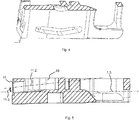
- the outlet opening 11, 21, 31 has a central axis 11.2, see fig. 5
- the chip 1 has a horizontal central plane 1.5, wherein the central axis 11.2 is inclined with respect to the horizontal plane 1.5 at an angle 11.3.
- One of the structures 10, 20, 30 is an oscillation structure 10 and the corresponding spray beam is an oscillating spray beam.
- the chip 1 has a top side 1.3, see fig. 3 , and a bottom side 1.4, see fig. 2 .
- the chip 1 furthermore comprises two spot beam structures 20, 30 for generating each a respective spot beam.
- the spot beam structures 10, 20 are arranged on the upper side 1.3 and the oscillation structure 10 is arranged on the lower side 1.4.
- the chip 1 has a collection chamber 2 from which three separate output channels 3, 4, 5 respectively lead to one of the structures 10, 20, 30.
- the collecting chamber 2 is open towards the upper side 1.3 and the lower side 1.4. It extends at least over 50% of the chip width 1.1 and at least 25% of the chip length 1.2.
- the output channels 4, 5 which lead to the point beam structures 20, 30 lead across a respective connection opening 4.1, 5.1 between the upper side and the lower side.
Landscapes
- Engineering & Computer Science (AREA)
- Water Supply & Treatment (AREA)
- Mechanical Engineering (AREA)
- Nozzles (AREA)
- Injection Moulding Of Plastics Or The Like (AREA)
Abstract
Description
- The invention relates to a chip for a windshield washer system of a vehicle front or rear window, to a windshield washer system of a vehicle front or rear window with a chip which is held in a chip holder, and to a method for producing a chip for a windshield washer system of a vehicle front or rear window.
- A chip or insert body of the type in question is shown in
EP 2144702 B1 . -
US 2005/0195239 A1 likewise shows a chip or insert body of the type in question, which consists of two parts connected by means of a film hinge. - The inventors have found this prior art to be disadvantageous since spray directions of the beam directions which can be produced by the insert body can be defined only to a limited extent and/or potential sealing problems arise because of a two-part design.
- It is the object of the present invention to improve these disadvantages.
- The object is achieved by the independent claims. Advantageous developments are defined in the dependent claims.
- In particular, the object is achieved by a chip for a windshield wiper system of a vehicle front or rear window, wherein the chip is injection-molded by an injection molding process, the chip being arranged to be inserted into a chip holder of the windshield washer system, wherein the chip has a structure for generating a spray beam, wherein the structure has at an end face of the chip an outlet opening having an opening edge, wherein the outlet opening is configured to allow the spray beam to emerge from the chip during operation of the windshield washer nozzle system onto the vehicle front or rear window, wherein the outlet opening is delimited by the opening edge all around the complete opening circumference by the chip, and the opening and the opening edge are formed all around and integrally by means of the injection molding process.
- The object is furthermore achieved in particular by a windshield washer system of a vehicle front or rear window with a chip according to the invention which is held in a chip holder.
The object is furthermore achieved in particular by a method for producing a chip for a windshield washer system of a vehicle front or rear window, wherein the chip is arranged to be inserted into a chip holder of the window washer system, wherein the chip has a structure for generating a spray beam, wherein the structure has at an end face of the chip an outlet opening and wherein the outlet opening has an opening edge, wherein the outlet opening is configured to allow the spray beam to emerge from the chip during operation of the windshield washer nozzle system onto the vehicle front or rear window; including the step - casting the chip by means of an injection molding process: wherein the opening and the opening edge are formed all around and integrally by means of the injection molding process such that the outlet opening is delimited continuously over the entire opening circumference by the chip by means of the opening edge.
- By this means, it is possible to change the outlet direction of the spray beam in any direction, even in the vertical direction. A chip folding design as shown in
US 2005/0195239 A1 mentioned at the beginning does not have to be used here. - In a further exemplary embodiment of the present invention, the outlet opening has a central axis and the chip has a horizontal central plane, wherein the central axis is inclined with respect to the horizontal plane at an angle.
- This produces a vertically angled spray beam, which is advantageous, for example, for certain windshields. In this case, the chip holder then does not have to be changed in its orientation (or not to the same extent), and a notch or groove also does not have to be provided on the chip holder in order to achieve said angling of the beam all around.
- In a further exemplary embodiment of the present invention, the structure is an oscillation structure and the spray beam is an oscillating spray beam.
- By this means, the advantages of the invention are achieved above all with an oscillation structure which is sensitive to opening modification - by the provision of an opening which is provided entirely in the chip and is surrounded by the chip, the opening orientation can be changed without the opening profile in partial regions having to change in the process.
In a further exemplary embodiment of the present invention, the chip has a top side and a bottom side, and wherein the chip further comprises two spot beam structures for generating each a respective spot beam, and the spot beam structures are arranged on one of the upper side and lower side, and the oscillation structure is arranged on the corresponding other one of the upper side and lower side, wherein the chip has a collection chamber from which three separate output channels respectively lead to one of the structures. - This permits a highly space-saving arrangement with a simultaneously large collection chamber since the collection chamber can be used for all three structures. In addition, this achieves a uniform generation of a spray beam since less mutual influencing occurs because of the separate channels.
- In a further exemplary embodiment of the present invention, the collecting chamber is open towards the upper side and the lower side.
- By this means, the collecting chamber can be provided with a very large volume. In contrast to the configuration shown in
EP2144702 mentioned at the beginning, separating surfaces between upper side and lower side in the region of thepreliminary chamber 20 there and of thecollecting chamber 30 there are therefore dispensed with. - In a further exemplary embodiment of the present invention, the collecting chamber extends at least over 50% of the chip width and at least 25% of the chip length.
- By this means, a highly uniform supply of the individual structures can be ensured.
- In a further exemplary embodiment of the present invention, the output channels which lead to the point beam structures lead across a respective connection opening between the upper side and the lower side.
- This achieves an even more uniform production of a spray beam since the length of the separate channels is increased even further, but in a space-saving manner.
- The invention will now be illustrated further by way of example with reference to drawings, in which:
- Figure 1
- shows a perspective front view,
- Figure 2
- shows a perspective bottom view,
- Figure 3
- shows a perspective top view,
- Figure 4
- shows a perspective sectional view,
- Figure 5
- shows a lateral sectional view of a chip according to the invention for a windshield washer system of a vehicle front or rear window.
- The
chip 1 is injection-molded by an injection molding process. It is arranged to be inserted into a chip holder of the windshield washer system. It hasstructures structures chip 1 an outlet opening 11, 21, 31 having an opening edge 11.1, 21.1, 31.1. Theoutlet openings chip 1 during operation of the windshield washer nozzle system onto the vehicle front or rear window. Theoutlet openings chip 1, and therespective opening fig. 5 , and thechip 1 has a horizontal central plane 1.5, wherein the central axis 11.2 is inclined with respect to the horizontal plane 1.5 at an angle 11.3. One of thestructures oscillation structure 10 and the corresponding spray beam is an oscillating spray beam. Thechip 1 has a top side 1.3, seefig. 3 , and a bottom side 1.4, seefig. 2 . Thechip 1 furthermore comprises twospot beam structures spot beam structures oscillation structure 10 is arranged on the lower side 1.4. Thechip 1 has acollection chamber 2 from which threeseparate output channels structures collecting chamber 2 is open towards the upper side 1.3 and the lower side 1.4. It extends at least over 50% of the chip width 1.1 and at least 25% of the chip length 1.2. Theoutput channels 4, 5 which lead to thepoint beam structures -
- 1
- Chip
- 1.1
- Chip width
- 1.2
- Chip length
- 1.3
- Upper side
- 1.4
- Lower side
- 1.5
- Horizontal central plane
- 2
- Collecting chamber
- 3
- Output channel
- 4
- Output channel
- 4.1
- Connecting opening
- 5
- Output channel
- 5.1
- Connecting opening
- 10
- Oscillation structure
- 11
- Outlet opening
- 11.1
- Opening edge
- 11.2
- Central axis
- 11.3
- Angle
- 20
- Spot beam structure
- 21
- Outlet opening
- 21.1
- Opening edge
- 30
- Spot beam structure
- 31
- Outlet opening
- 31.1
- Opening edge
Claims (9)
- A chip (1) for a windshield washer system of a vehicle front or rear window, wherein the chip (1) is injection-molded by an injection molding process, the chip (1) being arranged to be inserted into a chip holder of the windshield washer system, wherein the chip (1) has a structure (10, 20, 30) for generating a spray beam, wherein the structure (10, 20, 30) has at an end face of the chip (1) an outlet opening (11, 21, 31) having an opening edge (11.1, 21.1, 31.1), wherein the outlet opening (11, 21, 31) is configured to allow the spray beam to emerge from the chip (1) during operation of the windshield washer nozzle system onto the vehicle front or rear window, wherein the opening (11, 21, 31) is delimited by the opening edge (11.1, 21.1, 31.1) all around the complete opening circumference by the chip (1), and the opening (11, 21, 31) and the opening edge (11.1, 21.1, 31.1) are formed all around and integrally by means of the injection molding process.
- The chip (1) as claimed in claim 1, wherein the outlet opening (11, 21, 31) has a central axis (11.2) and the chip has a horizontal central plane (1.5), wherein the central axis (11.2) is inclined with respect to the horizontal plane (1.5) at an angle (11.3).
- The chip (1) as claimed in one of the preceding claims, wherein the structure (10) is an oscillation structure (10) and the spray beam is an oscillating spray beam.
- The chip (1) as claimed in claim 3, wherein the chip (1) has a top side (1.3) and a bottom side (1.4), and wherein the chip (1) further comprises two spot beam structures (20, 30) for generating each a respective spot beam, and wherein the spot beam structures (20, 30) are arranged on one of the upper side (1.3) and the lower side (1.4), and the oscillation structure (10) is arranged on the corresponding other one of the upper side (1.3) and lower side (1.4), wherein the chip (1) has a collection chamber (2) from which three separate output channels (3, 4, 5) respectively lead to one of the structures (10, 20, 30).
- The chip (1) as claimed in claim 4, wherein the collecting chamber (2) is open towards the upper side (1.3) and the lower side (1.4).
- The chip (1) as claimed in one of claims 4 and 5, wherein the collecting chamber extends at least over 50% of the chip width (1.1) and at least 25% of the chip length (1.2).
- The chip as claimed in one of claims 4 to 6, wherein the output channels (4, 5) which lead to the point beam structures (20, 30) lead across a respective connection opening (4.1, 5.1) between the upper side (1.3) and the lower side (1.4).
- A windshield washer system of a vehicle front or rear window with a chip (1) as claimed in one of the preceding claims, which is held in a chip holder.
- A method for producing a chip (1) for a windshield washer system of a vehicle front or rear window, wherein the chip (1) is arranged to be inserted into a chip holder of the window washer system, wherein the chip (1) has a structure (10, 20, 30) for generating a spray beam, wherein the structure (10, 20, 30) has at an end face of the chip (1) an outlet opening (11, 21, 31) having an opening edge (11.1, 21.1, 31.1), wherein the outlet opening (11, 21, 31) is configured to allow the spray beam to emerge from the chip (1) during operation of the windshield washer nozzle system onto the vehicle front or rear window; including the step - casting the chip (1) by means of an injection molding process: wherein the opening (11, 21, 31) and the opening edge (11.1, 21.1, 31.1) are formed all around and integrally by means of the injection molding process such that the outlet opening (11, 21, 31) is delimited continuously over the entire opening circumference by the chip (1) by means of the opening edge (11.1, 21.1, 31.1)
Applications Claiming Priority (1)
| Application Number | Priority Date | Filing Date | Title |
|---|---|---|---|
| DE102017110583.2A DE102017110583A1 (en) | 2017-05-16 | 2017-05-16 | Improved chip for a windscreen washer system with flexibly definable directional characteristics |
Publications (2)
| Publication Number | Publication Date |
|---|---|
| EP3403890A1 true EP3403890A1 (en) | 2018-11-21 |
| EP3403890B1 EP3403890B1 (en) | 2020-02-12 |
Family
ID=62089573
Family Applications (1)
| Application Number | Title | Priority Date | Filing Date |
|---|---|---|---|
| EP18169703.8A Active EP3403890B1 (en) | 2017-05-16 | 2018-04-27 | Improved chip for a windshield washer system with flexibly determinable directional characteristics |
Country Status (4)
| Country | Link |
|---|---|
| US (1) | US20180334141A1 (en) |
| EP (1) | EP3403890B1 (en) |
| CN (1) | CN108860069A (en) |
| DE (1) | DE102017110583A1 (en) |
Citations (3)
| Publication number | Priority date | Publication date | Assignee | Title |
|---|---|---|---|---|
| JP2004352167A (en) * | 2003-05-30 | 2004-12-16 | Asmo Co Ltd | Washer nozzle, nozzle chip and washer equipment |
| US20070257133A1 (en) * | 2004-09-27 | 2007-11-08 | Jens Bettenhausen | Nozzle Device For Cleaning A Window |
| WO2016060736A1 (en) * | 2014-10-15 | 2016-04-21 | Illinois Tool Works Inc. | Fluidic chip for spray nozzles |
Family Cites Families (6)
| Publication number | Priority date | Publication date | Assignee | Title |
|---|---|---|---|---|
| US4398664A (en) * | 1978-10-19 | 1983-08-16 | Bowles Fluidic Corporation | Fluid oscillator device and method |
| US7014131B2 (en) * | 2002-06-20 | 2006-03-21 | Bowles Fluidics Corporation | Multiple spray devices for automotive and other applications |
| US7302731B2 (en) * | 2002-12-11 | 2007-12-04 | Asmo Co., Ltd. | Washer equipment |
| US7677480B2 (en) * | 2003-09-29 | 2010-03-16 | Bowles Fluidics Corporation | Enclosures for fluidic oscillators |
| DE602004021898D1 (en) | 2004-02-20 | 2009-08-20 | Kautex Textron Gmbh & Co Kg | windshield washer |
| DE102007011331A1 (en) | 2007-03-08 | 2008-09-25 | A. Raymond Et Cie | Insert body for a spray nozzle arrangement and spray nozzle arrangement |
-
2017
- 2017-05-16 DE DE102017110583.2A patent/DE102017110583A1/en not_active Ceased
-
2018
- 2018-04-27 EP EP18169703.8A patent/EP3403890B1/en active Active
- 2018-05-02 US US15/968,952 patent/US20180334141A1/en not_active Abandoned
- 2018-05-08 CN CN201810430534.6A patent/CN108860069A/en active Pending
Patent Citations (3)
| Publication number | Priority date | Publication date | Assignee | Title |
|---|---|---|---|---|
| JP2004352167A (en) * | 2003-05-30 | 2004-12-16 | Asmo Co Ltd | Washer nozzle, nozzle chip and washer equipment |
| US20070257133A1 (en) * | 2004-09-27 | 2007-11-08 | Jens Bettenhausen | Nozzle Device For Cleaning A Window |
| WO2016060736A1 (en) * | 2014-10-15 | 2016-04-21 | Illinois Tool Works Inc. | Fluidic chip for spray nozzles |
Also Published As
| Publication number | Publication date |
|---|---|
| EP3403890B1 (en) | 2020-02-12 |
| CN108860069A (en) | 2018-11-23 |
| DE102017110583A1 (en) | 2018-11-22 |
| US20180334141A1 (en) | 2018-11-22 |
Similar Documents
| Publication | Publication Date | Title |
|---|---|---|
| CN101986017A (en) | Vehicle lamp | |
| DE102007011331A1 (en) | Insert body for a spray nozzle arrangement and spray nozzle arrangement | |
| US11415259B2 (en) | Hole plug for waste water | |
| US20180111457A1 (en) | Vehicle back door structure | |
| CN111267584B (en) | Fin for air outlet component | |
| EP3403890B1 (en) | Improved chip for a windshield washer system with flexibly determinable directional characteristics | |
| EP2578459B1 (en) | Washer nozzle | |
| EP3164282B1 (en) | Glass encapsulation structure and injection molding device | |
| KR101256266B1 (en) | Drainage arrangement | |
| US10926441B2 (en) | Liquid supply member and manufacturing method of liquid supply member | |
| KR20210076588A (en) | Vehicle body joint structure | |
| JP2019536609A (en) | Low flow small fluid spray nozzle assembly and method | |
| KR20090073877A (en) | Mold assembly | |
| KR100841720B1 (en) | Tube Head Forming Equipment of Dissimilar Material Tube Container | |
| JP2017078233A (en) | Parallel-type composite melt-blown spinning method and parallel-type composite melt-blown spinning device | |
| KR20010052940A (en) | Fluidic oscillator, part designed to be incorporated in a fluidic oscillator and method for making such a fluidic oscillator | |
| EP1454368B1 (en) | Method for the production of light emitting diodes | |
| EP2213442B1 (en) | An assembly and a method for extruding a tire component | |
| AU3811700A (en) | Two-chamber tube | |
| JPH10217281A (en) | Filter for injection molding | |
| CN109403756B (en) | An inner door handle and a mold for manufacturing the handle | |
| US20040168373A1 (en) | Sealing structure of automobile | |
| CN216267381U (en) | Be used for fashioned mould of product of bending and injection molding machine | |
| CN223493771U (en) | Hot nozzle assembly and hot runner system | |
| JP2020090925A (en) | Intake duct and method of manufacturing intake duct |
Legal Events
| Date | Code | Title | Description |
|---|---|---|---|
| PUAI | Public reference made under article 153(3) epc to a published international application that has entered the european phase |
Free format text: ORIGINAL CODE: 0009012 |
|
| STAA | Information on the status of an ep patent application or granted ep patent |
Free format text: STATUS: THE APPLICATION HAS BEEN PUBLISHED |
|
| AK | Designated contracting states |
Kind code of ref document: A1 Designated state(s): AL AT BE BG CH CY CZ DE DK EE ES FI FR GB GR HR HU IE IS IT LI LT LU LV MC MK MT NL NO PL PT RO RS SE SI SK SM TR |
|
| AX | Request for extension of the european patent |
Extension state: BA ME |
|
| STAA | Information on the status of an ep patent application or granted ep patent |
Free format text: STATUS: REQUEST FOR EXAMINATION WAS MADE |
|
| 17P | Request for examination filed |
Effective date: 20190520 |
|
| RBV | Designated contracting states (corrected) |
Designated state(s): AL AT BE BG CH CY CZ DE DK EE ES FI FR GB GR HR HU IE IS IT LI LT LU LV MC MK MT NL NO PL PT RO RS SE SI SK SM TR |
|
| GRAP | Despatch of communication of intention to grant a patent |
Free format text: ORIGINAL CODE: EPIDOSNIGR1 |
|
| STAA | Information on the status of an ep patent application or granted ep patent |
Free format text: STATUS: GRANT OF PATENT IS INTENDED |
|
| INTG | Intention to grant announced |
Effective date: 20190913 |
|
| GRAS | Grant fee paid |
Free format text: ORIGINAL CODE: EPIDOSNIGR3 |
|
| GRAA | (expected) grant |
Free format text: ORIGINAL CODE: 0009210 |
|
| STAA | Information on the status of an ep patent application or granted ep patent |
Free format text: STATUS: THE PATENT HAS BEEN GRANTED |
|
| AK | Designated contracting states |
Kind code of ref document: B1 Designated state(s): AL AT BE BG CH CY CZ DE DK EE ES FI FR GB GR HR HU IE IS IT LI LT LU LV MC MK MT NL NO PL PT RO RS SE SI SK SM TR |
|
| REG | Reference to a national code |
Ref country code: GB Ref legal event code: FG4D |
|
| REG | Reference to a national code |
Ref country code: CH Ref legal event code: EP |
|
| REG | Reference to a national code |
Ref country code: AT Ref legal event code: REF Ref document number: 1231696 Country of ref document: AT Kind code of ref document: T Effective date: 20200215 |
|
| REG | Reference to a national code |
Ref country code: IE Ref legal event code: FG4D |
|
| REG | Reference to a national code |
Ref country code: DE Ref legal event code: R096 Ref document number: 602018002342 Country of ref document: DE |
|
| PG25 | Lapsed in a contracting state [announced via postgrant information from national office to epo] |
Ref country code: RS Free format text: LAPSE BECAUSE OF FAILURE TO SUBMIT A TRANSLATION OF THE DESCRIPTION OR TO PAY THE FEE WITHIN THE PRESCRIBED TIME-LIMIT Effective date: 20200212 Ref country code: NO Free format text: LAPSE BECAUSE OF FAILURE TO SUBMIT A TRANSLATION OF THE DESCRIPTION OR TO PAY THE FEE WITHIN THE PRESCRIBED TIME-LIMIT Effective date: 20200512 Ref country code: FI Free format text: LAPSE BECAUSE OF FAILURE TO SUBMIT A TRANSLATION OF THE DESCRIPTION OR TO PAY THE FEE WITHIN THE PRESCRIBED TIME-LIMIT Effective date: 20200212 |
|
| REG | Reference to a national code |
Ref country code: LT Ref legal event code: MG4D |
|
| REG | Reference to a national code |
Ref country code: NL Ref legal event code: MP Effective date: 20200212 |
|
| PG25 | Lapsed in a contracting state [announced via postgrant information from national office to epo] |
Ref country code: LV Free format text: LAPSE BECAUSE OF FAILURE TO SUBMIT A TRANSLATION OF THE DESCRIPTION OR TO PAY THE FEE WITHIN THE PRESCRIBED TIME-LIMIT Effective date: 20200212 Ref country code: SE Free format text: LAPSE BECAUSE OF FAILURE TO SUBMIT A TRANSLATION OF THE DESCRIPTION OR TO PAY THE FEE WITHIN THE PRESCRIBED TIME-LIMIT Effective date: 20200212 Ref country code: HR Free format text: LAPSE BECAUSE OF FAILURE TO SUBMIT A TRANSLATION OF THE DESCRIPTION OR TO PAY THE FEE WITHIN THE PRESCRIBED TIME-LIMIT Effective date: 20200212 Ref country code: IS Free format text: LAPSE BECAUSE OF FAILURE TO SUBMIT A TRANSLATION OF THE DESCRIPTION OR TO PAY THE FEE WITHIN THE PRESCRIBED TIME-LIMIT Effective date: 20200612 Ref country code: GR Free format text: LAPSE BECAUSE OF FAILURE TO SUBMIT A TRANSLATION OF THE DESCRIPTION OR TO PAY THE FEE WITHIN THE PRESCRIBED TIME-LIMIT Effective date: 20200513 Ref country code: BG Free format text: LAPSE BECAUSE OF FAILURE TO SUBMIT A TRANSLATION OF THE DESCRIPTION OR TO PAY THE FEE WITHIN THE PRESCRIBED TIME-LIMIT Effective date: 20200512 |
|
| PG25 | Lapsed in a contracting state [announced via postgrant information from national office to epo] |
Ref country code: NL Free format text: LAPSE BECAUSE OF FAILURE TO SUBMIT A TRANSLATION OF THE DESCRIPTION OR TO PAY THE FEE WITHIN THE PRESCRIBED TIME-LIMIT Effective date: 20200212 |
|
| PG25 | Lapsed in a contracting state [announced via postgrant information from national office to epo] |
Ref country code: SK Free format text: LAPSE BECAUSE OF FAILURE TO SUBMIT A TRANSLATION OF THE DESCRIPTION OR TO PAY THE FEE WITHIN THE PRESCRIBED TIME-LIMIT Effective date: 20200212 Ref country code: RO Free format text: LAPSE BECAUSE OF FAILURE TO SUBMIT A TRANSLATION OF THE DESCRIPTION OR TO PAY THE FEE WITHIN THE PRESCRIBED TIME-LIMIT Effective date: 20200212 Ref country code: CZ Free format text: LAPSE BECAUSE OF FAILURE TO SUBMIT A TRANSLATION OF THE DESCRIPTION OR TO PAY THE FEE WITHIN THE PRESCRIBED TIME-LIMIT Effective date: 20200212 Ref country code: LT Free format text: LAPSE BECAUSE OF FAILURE TO SUBMIT A TRANSLATION OF THE DESCRIPTION OR TO PAY THE FEE WITHIN THE PRESCRIBED TIME-LIMIT Effective date: 20200212 Ref country code: PT Free format text: LAPSE BECAUSE OF FAILURE TO SUBMIT A TRANSLATION OF THE DESCRIPTION OR TO PAY THE FEE WITHIN THE PRESCRIBED TIME-LIMIT Effective date: 20200705 Ref country code: DK Free format text: LAPSE BECAUSE OF FAILURE TO SUBMIT A TRANSLATION OF THE DESCRIPTION OR TO PAY THE FEE WITHIN THE PRESCRIBED TIME-LIMIT Effective date: 20200212 Ref country code: ES Free format text: LAPSE BECAUSE OF FAILURE TO SUBMIT A TRANSLATION OF THE DESCRIPTION OR TO PAY THE FEE WITHIN THE PRESCRIBED TIME-LIMIT Effective date: 20200212 Ref country code: SM Free format text: LAPSE BECAUSE OF FAILURE TO SUBMIT A TRANSLATION OF THE DESCRIPTION OR TO PAY THE FEE WITHIN THE PRESCRIBED TIME-LIMIT Effective date: 20200212 Ref country code: EE Free format text: LAPSE BECAUSE OF FAILURE TO SUBMIT A TRANSLATION OF THE DESCRIPTION OR TO PAY THE FEE WITHIN THE PRESCRIBED TIME-LIMIT Effective date: 20200212 |
|
| REG | Reference to a national code |
Ref country code: DE Ref legal event code: R119 Ref document number: 602018002342 Country of ref document: DE |
|
| REG | Reference to a national code |
Ref country code: AT Ref legal event code: MK05 Ref document number: 1231696 Country of ref document: AT Kind code of ref document: T Effective date: 20200212 |
|
| PG25 | Lapsed in a contracting state [announced via postgrant information from national office to epo] |
Ref country code: MC Free format text: LAPSE BECAUSE OF FAILURE TO SUBMIT A TRANSLATION OF THE DESCRIPTION OR TO PAY THE FEE WITHIN THE PRESCRIBED TIME-LIMIT Effective date: 20200212 |
|
| PLBE | No opposition filed within time limit |
Free format text: ORIGINAL CODE: 0009261 |
|
| STAA | Information on the status of an ep patent application or granted ep patent |
Free format text: STATUS: NO OPPOSITION FILED WITHIN TIME LIMIT |
|
| 26N | No opposition filed |
Effective date: 20201113 |
|
| PG25 | Lapsed in a contracting state [announced via postgrant information from national office to epo] |
Ref country code: FR Free format text: LAPSE BECAUSE OF NON-PAYMENT OF DUE FEES Effective date: 20200430 Ref country code: DE Free format text: LAPSE BECAUSE OF NON-PAYMENT OF DUE FEES Effective date: 20201103 Ref country code: IT Free format text: LAPSE BECAUSE OF FAILURE TO SUBMIT A TRANSLATION OF THE DESCRIPTION OR TO PAY THE FEE WITHIN THE PRESCRIBED TIME-LIMIT Effective date: 20200212 Ref country code: LU Free format text: LAPSE BECAUSE OF NON-PAYMENT OF DUE FEES Effective date: 20200427 Ref country code: AT Free format text: LAPSE BECAUSE OF FAILURE TO SUBMIT A TRANSLATION OF THE DESCRIPTION OR TO PAY THE FEE WITHIN THE PRESCRIBED TIME-LIMIT Effective date: 20200212 |
|
| REG | Reference to a national code |
Ref country code: BE Ref legal event code: MM Effective date: 20200430 |
|
| PG25 | Lapsed in a contracting state [announced via postgrant information from national office to epo] |
Ref country code: SI Free format text: LAPSE BECAUSE OF FAILURE TO SUBMIT A TRANSLATION OF THE DESCRIPTION OR TO PAY THE FEE WITHIN THE PRESCRIBED TIME-LIMIT Effective date: 20200212 Ref country code: PL Free format text: LAPSE BECAUSE OF FAILURE TO SUBMIT A TRANSLATION OF THE DESCRIPTION OR TO PAY THE FEE WITHIN THE PRESCRIBED TIME-LIMIT Effective date: 20200212 Ref country code: BE Free format text: LAPSE BECAUSE OF NON-PAYMENT OF DUE FEES Effective date: 20200430 |
|
| PG25 | Lapsed in a contracting state [announced via postgrant information from national office to epo] |
Ref country code: IE Free format text: LAPSE BECAUSE OF NON-PAYMENT OF DUE FEES Effective date: 20200427 |
|
| PG25 | Lapsed in a contracting state [announced via postgrant information from national office to epo] |
Ref country code: CH Free format text: LAPSE BECAUSE OF NON-PAYMENT OF DUE FEES Effective date: 20210430 Ref country code: LI Free format text: LAPSE BECAUSE OF NON-PAYMENT OF DUE FEES Effective date: 20210430 |
|
| PG25 | Lapsed in a contracting state [announced via postgrant information from national office to epo] |
Ref country code: TR Free format text: LAPSE BECAUSE OF FAILURE TO SUBMIT A TRANSLATION OF THE DESCRIPTION OR TO PAY THE FEE WITHIN THE PRESCRIBED TIME-LIMIT Effective date: 20200212 Ref country code: MT Free format text: LAPSE BECAUSE OF FAILURE TO SUBMIT A TRANSLATION OF THE DESCRIPTION OR TO PAY THE FEE WITHIN THE PRESCRIBED TIME-LIMIT Effective date: 20200212 Ref country code: CY Free format text: LAPSE BECAUSE OF FAILURE TO SUBMIT A TRANSLATION OF THE DESCRIPTION OR TO PAY THE FEE WITHIN THE PRESCRIBED TIME-LIMIT Effective date: 20200212 |
|
| PG25 | Lapsed in a contracting state [announced via postgrant information from national office to epo] |
Ref country code: MK Free format text: LAPSE BECAUSE OF FAILURE TO SUBMIT A TRANSLATION OF THE DESCRIPTION OR TO PAY THE FEE WITHIN THE PRESCRIBED TIME-LIMIT Effective date: 20200212 Ref country code: AL Free format text: LAPSE BECAUSE OF FAILURE TO SUBMIT A TRANSLATION OF THE DESCRIPTION OR TO PAY THE FEE WITHIN THE PRESCRIBED TIME-LIMIT Effective date: 20200212 |
|
| GBPC | Gb: european patent ceased through non-payment of renewal fee |
Effective date: 20220427 |
|
| PG25 | Lapsed in a contracting state [announced via postgrant information from national office to epo] |
Ref country code: GB Free format text: LAPSE BECAUSE OF NON-PAYMENT OF DUE FEES Effective date: 20220427 |