EP3403874A1 - A motor vehicle seating arrangement - Google Patents
A motor vehicle seating arrangement Download PDFInfo
- Publication number
- EP3403874A1 EP3403874A1 EP18155499.9A EP18155499A EP3403874A1 EP 3403874 A1 EP3403874 A1 EP 3403874A1 EP 18155499 A EP18155499 A EP 18155499A EP 3403874 A1 EP3403874 A1 EP 3403874A1
- Authority
- EP
- European Patent Office
- Prior art keywords
- seat
- motor vehicle
- hand side
- pair
- seating arrangement
- Prior art date
- Legal status (The legal status is an assumption and is not a legal conclusion. Google has not performed a legal analysis and makes no representation as to the accuracy of the status listed.)
- Granted
Links
Images






Classifications
-
- B—PERFORMING OPERATIONS; TRANSPORTING
- B60—VEHICLES IN GENERAL
- B60N—SEATS SPECIALLY ADAPTED FOR VEHICLES; VEHICLE PASSENGER ACCOMMODATION NOT OTHERWISE PROVIDED FOR
- B60N2/00—Seats specially adapted for vehicles; Arrangement or mounting of seats in vehicles
- B60N2/005—Arrangement or mounting of seats in vehicles, e.g. dismountable auxiliary seats
- B60N2/01—Arrangement of seats relative to one another
-
- B—PERFORMING OPERATIONS; TRANSPORTING
- B60—VEHICLES IN GENERAL
- B60N—SEATS SPECIALLY ADAPTED FOR VEHICLES; VEHICLE PASSENGER ACCOMMODATION NOT OTHERWISE PROVIDED FOR
- B60N2/00—Seats specially adapted for vehicles; Arrangement or mounting of seats in vehicles
- B60N2/02—Seats specially adapted for vehicles; Arrangement or mounting of seats in vehicles the seat or part thereof being movable, e.g. adjustable
- B60N2/0292—Multiple configuration seats, e.g. for spacious vehicles or mini-buses
-
- B—PERFORMING OPERATIONS; TRANSPORTING
- B60—VEHICLES IN GENERAL
- B60N—SEATS SPECIALLY ADAPTED FOR VEHICLES; VEHICLE PASSENGER ACCOMMODATION NOT OTHERWISE PROVIDED FOR
- B60N2/00—Seats specially adapted for vehicles; Arrangement or mounting of seats in vehicles
- B60N2/24—Seats specially adapted for vehicles; Arrangement or mounting of seats in vehicles for particular purposes or particular vehicles
- B60N2/30—Non-dismountable or dismountable seats storable in a non-use position, e.g. foldable spare seats
-
- B—PERFORMING OPERATIONS; TRANSPORTING
- B60—VEHICLES IN GENERAL
- B60N—SEATS SPECIALLY ADAPTED FOR VEHICLES; VEHICLE PASSENGER ACCOMMODATION NOT OTHERWISE PROVIDED FOR
- B60N2/00—Seats specially adapted for vehicles; Arrangement or mounting of seats in vehicles
- B60N2/005—Arrangement or mounting of seats in vehicles, e.g. dismountable auxiliary seats
-
- B—PERFORMING OPERATIONS; TRANSPORTING
- B60—VEHICLES IN GENERAL
- B60N—SEATS SPECIALLY ADAPTED FOR VEHICLES; VEHICLE PASSENGER ACCOMMODATION NOT OTHERWISE PROVIDED FOR
- B60N2/00—Seats specially adapted for vehicles; Arrangement or mounting of seats in vehicles
- B60N2/005—Arrangement or mounting of seats in vehicles, e.g. dismountable auxiliary seats
- B60N2/01—Arrangement of seats relative to one another
- B60N2/012—The seat support being a part of the vehicle body or chassis
-
- B—PERFORMING OPERATIONS; TRANSPORTING
- B60—VEHICLES IN GENERAL
- B60N—SEATS SPECIALLY ADAPTED FOR VEHICLES; VEHICLE PASSENGER ACCOMMODATION NOT OTHERWISE PROVIDED FOR
- B60N2/00—Seats specially adapted for vehicles; Arrangement or mounting of seats in vehicles
- B60N2/005—Arrangement or mounting of seats in vehicles, e.g. dismountable auxiliary seats
- B60N2/015—Attaching seats directly to vehicle chassis
- B60N2/01508—Attaching seats directly to vehicle chassis using quick release attachments
- B60N2/01516—Attaching seats directly to vehicle chassis using quick release attachments with locking mechanisms
- B60N2/01583—Attaching seats directly to vehicle chassis using quick release attachments with locking mechanisms locking on transversal elements on the vehicle floor or rail, e.g. transversal rods
-
- B—PERFORMING OPERATIONS; TRANSPORTING
- B60—VEHICLES IN GENERAL
- B60N—SEATS SPECIALLY ADAPTED FOR VEHICLES; VEHICLE PASSENGER ACCOMMODATION NOT OTHERWISE PROVIDED FOR
- B60N2/00—Seats specially adapted for vehicles; Arrangement or mounting of seats in vehicles
- B60N2/02—Seats specially adapted for vehicles; Arrangement or mounting of seats in vehicles the seat or part thereof being movable, e.g. adjustable
- B60N2/04—Seats specially adapted for vehicles; Arrangement or mounting of seats in vehicles the seat or part thereof being movable, e.g. adjustable the whole seat being movable
- B60N2/06—Seats specially adapted for vehicles; Arrangement or mounting of seats in vehicles the seat or part thereof being movable, e.g. adjustable the whole seat being movable slidable
-
- B—PERFORMING OPERATIONS; TRANSPORTING
- B60—VEHICLES IN GENERAL
- B60N—SEATS SPECIALLY ADAPTED FOR VEHICLES; VEHICLE PASSENGER ACCOMMODATION NOT OTHERWISE PROVIDED FOR
- B60N2/00—Seats specially adapted for vehicles; Arrangement or mounting of seats in vehicles
- B60N2/02—Seats specially adapted for vehicles; Arrangement or mounting of seats in vehicles the seat or part thereof being movable, e.g. adjustable
- B60N2/04—Seats specially adapted for vehicles; Arrangement or mounting of seats in vehicles the seat or part thereof being movable, e.g. adjustable the whole seat being movable
- B60N2/06—Seats specially adapted for vehicles; Arrangement or mounting of seats in vehicles the seat or part thereof being movable, e.g. adjustable the whole seat being movable slidable
- B60N2/065—Rear seats
-
- B—PERFORMING OPERATIONS; TRANSPORTING
- B60—VEHICLES IN GENERAL
- B60N—SEATS SPECIALLY ADAPTED FOR VEHICLES; VEHICLE PASSENGER ACCOMMODATION NOT OTHERWISE PROVIDED FOR
- B60N2/00—Seats specially adapted for vehicles; Arrangement or mounting of seats in vehicles
- B60N2/02—Seats specially adapted for vehicles; Arrangement or mounting of seats in vehicles the seat or part thereof being movable, e.g. adjustable
- B60N2/04—Seats specially adapted for vehicles; Arrangement or mounting of seats in vehicles the seat or part thereof being movable, e.g. adjustable the whole seat being movable
- B60N2/06—Seats specially adapted for vehicles; Arrangement or mounting of seats in vehicles the seat or part thereof being movable, e.g. adjustable the whole seat being movable slidable
- B60N2/07—Slide construction
-
- B—PERFORMING OPERATIONS; TRANSPORTING
- B60—VEHICLES IN GENERAL
- B60N—SEATS SPECIALLY ADAPTED FOR VEHICLES; VEHICLE PASSENGER ACCOMMODATION NOT OTHERWISE PROVIDED FOR
- B60N2/00—Seats specially adapted for vehicles; Arrangement or mounting of seats in vehicles
- B60N2/02—Seats specially adapted for vehicles; Arrangement or mounting of seats in vehicles the seat or part thereof being movable, e.g. adjustable
- B60N2/04—Seats specially adapted for vehicles; Arrangement or mounting of seats in vehicles the seat or part thereof being movable, e.g. adjustable the whole seat being movable
- B60N2/12—Seats specially adapted for vehicles; Arrangement or mounting of seats in vehicles the seat or part thereof being movable, e.g. adjustable the whole seat being movable slidable and tiltable
-
- B—PERFORMING OPERATIONS; TRANSPORTING
- B60—VEHICLES IN GENERAL
- B60N—SEATS SPECIALLY ADAPTED FOR VEHICLES; VEHICLE PASSENGER ACCOMMODATION NOT OTHERWISE PROVIDED FOR
- B60N2/00—Seats specially adapted for vehicles; Arrangement or mounting of seats in vehicles
- B60N2/02—Seats specially adapted for vehicles; Arrangement or mounting of seats in vehicles the seat or part thereof being movable, e.g. adjustable
- B60N2/20—Seats specially adapted for vehicles; Arrangement or mounting of seats in vehicles the seat or part thereof being movable, e.g. adjustable the back-rest being tiltable, e.g. to permit easy access
-
- B—PERFORMING OPERATIONS; TRANSPORTING
- B60—VEHICLES IN GENERAL
- B60N—SEATS SPECIALLY ADAPTED FOR VEHICLES; VEHICLE PASSENGER ACCOMMODATION NOT OTHERWISE PROVIDED FOR
- B60N2/00—Seats specially adapted for vehicles; Arrangement or mounting of seats in vehicles
- B60N2/24—Seats specially adapted for vehicles; Arrangement or mounting of seats in vehicles for particular purposes or particular vehicles
- B60N2/26—Seats specially adapted for vehicles; Arrangement or mounting of seats in vehicles for particular purposes or particular vehicles for children
-
- B—PERFORMING OPERATIONS; TRANSPORTING
- B60—VEHICLES IN GENERAL
- B60N—SEATS SPECIALLY ADAPTED FOR VEHICLES; VEHICLE PASSENGER ACCOMMODATION NOT OTHERWISE PROVIDED FOR
- B60N2/00—Seats specially adapted for vehicles; Arrangement or mounting of seats in vehicles
- B60N2/24—Seats specially adapted for vehicles; Arrangement or mounting of seats in vehicles for particular purposes or particular vehicles
- B60N2/26—Seats specially adapted for vehicles; Arrangement or mounting of seats in vehicles for particular purposes or particular vehicles for children
- B60N2/28—Seats readily mountable on, and dismountable from, existing seats or other parts of the vehicle
- B60N2/2803—Adaptations for seat belts
- B60N2/2806—Adaptations for seat belts for securing the child seat to the vehicle
-
- B—PERFORMING OPERATIONS; TRANSPORTING
- B60—VEHICLES IN GENERAL
- B60N—SEATS SPECIALLY ADAPTED FOR VEHICLES; VEHICLE PASSENGER ACCOMMODATION NOT OTHERWISE PROVIDED FOR
- B60N2/00—Seats specially adapted for vehicles; Arrangement or mounting of seats in vehicles
- B60N2/24—Seats specially adapted for vehicles; Arrangement or mounting of seats in vehicles for particular purposes or particular vehicles
- B60N2/26—Seats specially adapted for vehicles; Arrangement or mounting of seats in vehicles for particular purposes or particular vehicles for children
- B60N2/28—Seats readily mountable on, and dismountable from, existing seats or other parts of the vehicle
- B60N2/283—Seats readily mountable on, and dismountable from, existing seats or other parts of the vehicle suspended
-
- B—PERFORMING OPERATIONS; TRANSPORTING
- B60—VEHICLES IN GENERAL
- B60N—SEATS SPECIALLY ADAPTED FOR VEHICLES; VEHICLE PASSENGER ACCOMMODATION NOT OTHERWISE PROVIDED FOR
- B60N2/00—Seats specially adapted for vehicles; Arrangement or mounting of seats in vehicles
- B60N2/24—Seats specially adapted for vehicles; Arrangement or mounting of seats in vehicles for particular purposes or particular vehicles
- B60N2/30—Non-dismountable or dismountable seats storable in a non-use position, e.g. foldable spare seats
- B60N2/3002—Non-dismountable or dismountable seats storable in a non-use position, e.g. foldable spare seats back-rest movements
- B60N2/3004—Non-dismountable or dismountable seats storable in a non-use position, e.g. foldable spare seats back-rest movements by rotation only
- B60N2/3009—Non-dismountable or dismountable seats storable in a non-use position, e.g. foldable spare seats back-rest movements by rotation only about transversal axis
- B60N2/3011—Non-dismountable or dismountable seats storable in a non-use position, e.g. foldable spare seats back-rest movements by rotation only about transversal axis the back-rest being hinged on the cushion, e.g. "portefeuille movement"
-
- B—PERFORMING OPERATIONS; TRANSPORTING
- B60—VEHICLES IN GENERAL
- B60N—SEATS SPECIALLY ADAPTED FOR VEHICLES; VEHICLE PASSENGER ACCOMMODATION NOT OTHERWISE PROVIDED FOR
- B60N2/00—Seats specially adapted for vehicles; Arrangement or mounting of seats in vehicles
- B60N2/24—Seats specially adapted for vehicles; Arrangement or mounting of seats in vehicles for particular purposes or particular vehicles
- B60N2/30—Non-dismountable or dismountable seats storable in a non-use position, e.g. foldable spare seats
- B60N2/3038—Cushion movements
- B60N2/304—Cushion movements by rotation only
- B60N2/3043—Cushion movements by rotation only about longitudinal axis
-
- B—PERFORMING OPERATIONS; TRANSPORTING
- B60—VEHICLES IN GENERAL
- B60N—SEATS SPECIALLY ADAPTED FOR VEHICLES; VEHICLE PASSENGER ACCOMMODATION NOT OTHERWISE PROVIDED FOR
- B60N2/00—Seats specially adapted for vehicles; Arrangement or mounting of seats in vehicles
- B60N2/24—Seats specially adapted for vehicles; Arrangement or mounting of seats in vehicles for particular purposes or particular vehicles
- B60N2/30—Non-dismountable or dismountable seats storable in a non-use position, e.g. foldable spare seats
- B60N2/3088—Non-dismountable or dismountable seats storable in a non-use position, e.g. foldable spare seats characterised by the mechanical link
- B60N2/3093—Non-dismountable or dismountable seats storable in a non-use position, e.g. foldable spare seats characterised by the mechanical link slides
-
- B—PERFORMING OPERATIONS; TRANSPORTING
- B60—VEHICLES IN GENERAL
- B60N—SEATS SPECIALLY ADAPTED FOR VEHICLES; VEHICLE PASSENGER ACCOMMODATION NOT OTHERWISE PROVIDED FOR
- B60N2/00—Seats specially adapted for vehicles; Arrangement or mounting of seats in vehicles
- B60N2/24—Seats specially adapted for vehicles; Arrangement or mounting of seats in vehicles for particular purposes or particular vehicles
- B60N2/30—Non-dismountable or dismountable seats storable in a non-use position, e.g. foldable spare seats
- B60N2/3097—Dismountable seats storable in a non-use position
-
- B—PERFORMING OPERATIONS; TRANSPORTING
- B60—VEHICLES IN GENERAL
- B60N—SEATS SPECIALLY ADAPTED FOR VEHICLES; VEHICLE PASSENGER ACCOMMODATION NOT OTHERWISE PROVIDED FOR
- B60N3/00—Arrangements or adaptations of other passenger fittings, not otherwise provided for
- B60N3/001—Arrangements or adaptations of other passenger fittings, not otherwise provided for of tables or trays
-
- B—PERFORMING OPERATIONS; TRANSPORTING
- B60—VEHICLES IN GENERAL
- B60N—SEATS SPECIALLY ADAPTED FOR VEHICLES; VEHICLE PASSENGER ACCOMMODATION NOT OTHERWISE PROVIDED FOR
- B60N3/00—Arrangements or adaptations of other passenger fittings, not otherwise provided for
- B60N3/10—Arrangements or adaptations of other passenger fittings, not otherwise provided for of receptacles for food or beverages, e.g. refrigerated
- B60N3/103—Arrangements or adaptations of other passenger fittings, not otherwise provided for of receptacles for food or beverages, e.g. refrigerated detachable
-
- B—PERFORMING OPERATIONS; TRANSPORTING
- B60—VEHICLES IN GENERAL
- B60R—VEHICLES, VEHICLE FITTINGS, OR VEHICLE PARTS, NOT OTHERWISE PROVIDED FOR
- B60R7/00—Stowing or holding appliances inside vehicle primarily intended for personal property smaller than suit-cases, e.g. travelling articles, or maps
- B60R7/04—Stowing or holding appliances inside vehicle primarily intended for personal property smaller than suit-cases, e.g. travelling articles, or maps in driver or passenger space, e.g. using racks
- B60R7/043—Stowing or holding appliances inside vehicle primarily intended for personal property smaller than suit-cases, e.g. travelling articles, or maps in driver or passenger space, e.g. using racks mounted on or under a seat
-
- B—PERFORMING OPERATIONS; TRANSPORTING
- B60—VEHICLES IN GENERAL
- B60N—SEATS SPECIALLY ADAPTED FOR VEHICLES; VEHICLE PASSENGER ACCOMMODATION NOT OTHERWISE PROVIDED FOR
- B60N2205/00—General mechanical or structural details
- B60N2205/30—Seat or seat parts characterised by comprising plural parts or pieces
Definitions
- This invention relates to motor vehicles and in particular to a motor vehicle seating arrangement having improved utility.
- a motor vehicle seating arrangement comprising a pair of outboard seats spaced apart to define therebetween a gap into which an item of utility is fitted wherein the item of utility is supported solely by the two outboard seats.
- the item of utility may be supported on a left hand side by a left hand side one of the pair of outboard seats.
- the item of utility may advantageously be slidingly supported on the left hand side by a sliding connection with the left hand side one of the pair of outboard seats.
- the item of utility may be supported on a right hand side by a right hand side one of the pair of outboard seats.
- the item of utility may advantageously be slidingly supported on a right hand side by a sliding connection with the right hand side one of the pair of outboard seats.
- the item of utility may be a central seat.
- the central seat may have a backrest and a seat base by which it is supported.
- the seat base of the central seat may be mounted on a seat support member and the seat support member may have a pair of recesses on a left hand side used to connect the seat support member on the left hand side to a pair of support pins forming part of a slide mechanism located on the left hand side one of the pair of outboard seats.
- the slide mechanism located on the left hand side one of the pair of outboard seats may be fastened to a seat pedestal of the left hand side one of the pair of outboard seats.
- the seat base of the central seat may be mounted on a seat support member and the seat support member may have a pair of recesses on a right hand side used to connect the seat support member on the right hand side to a pair of support pins forming part of a slide mechanism located on the right hand side one of the pair of outboard seats.
- the slide mechanism located on the right hand side one of the pair of outboard seats may be fastened to a seat pedestal of the right hand side one of the pair of outboard seats.
- Each of the outboard seats may have a backrest, a seat base and a seat pedestal for mounting the respective seat on a floor of a motor vehicle.
- Each of the seat pedestals may include a floor latch mechanism and, when the floor latch mechanism is fully released, the respective seat of which the pedestal forms a part may be removable from the motor vehicle.
- the respective seat of which the pedestal forms a part may be slideable in a fore-aft direction of the motor vehicle.
- the item of utility may be one of a child seat, a table, a storage box, a storage locker and an entertainment centre.
- a motor vehicle having a motor vehicle seating arrangement constructed in accordance with said first aspect of the invention.
- the motor vehicle seating arrangement may be a second row seating arrangement.
- a motor vehicle 1 has a side door aperture 2 to provide access to a passenger compartment 3 of the motor vehicle 1 in which is mounted a motor vehicle seating arrangement 50 of a type conforming to the requirements of this invention as set out in the accompanying claims that is to say the motor vehicle seating arrangement 50 has an item of utility in the form of a suspended central seat supported by a pair of outboard seats.
- the motor vehicle seating arrangement 50 is in the form of a second row of seating and is mounted on a floor 10 of the motor vehicle 1 so as be positioned in front of a third row of seating 7 (shown in dotted outline).
- the motor vehicle seating arrangement 50 is mounted so as to be positioned between a front upright 5 and a rear upright 6 which define front and rear edges of the side door aperture 2.
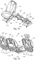
- FIG.1a to 1i there is shown a first embodiment of a motor vehicle seating arrangement 100.
- the seating arrangement 100 comprises of a right hand side outboard seat 105, a left hand side outboard seat 106 and an item of utility for use by occupants of the motor vehicle in the form of a central seat 107 that is located in a gap defined between the pair of outboard seats 105, 106. It will be appreciated that the seats 105, 106, 107 are mounted so as to face towards a front of the motor vehicle.
- the right hand side outboard seat 105 has a backrest 102 and a seat base 103 and is mounted on a floor of a motor vehicle such as the floor 10 of the motor vehicle 1 shown in Fig.5 via a seat pedestal 115.
- the seat pedestal 115 is moveably mounted on the floor 10 so as to be selectively slideable in a fore-aft direction of the motor vehicle 1 (see arrow F-A on Fig.1c ). That is to say, the seat pedestal 115 can be slid forwards or rearwards relative to the floor 10 of the motor vehicle 1.
- a release lever 117 is provided on the seat pedestal 115 to release floor latches (not shown) used to hold the seat pedestal 115 in position on the floor 10. By releasing these floor latches the seat pedestal 115 and the associated seat 105 can be removed from the motor vehicle 1.
- the left hand side outboard seat 106 has a backrest 112 and a seat base 113 and is mounted on the floor 10 of the motor vehicle 1 via a seat pedestal 116.
- the seat pedestal 116 is moveably mounted on the floor 10 so as to be selectively moveable in a fore-aft direction of the motor vehicle 1. That is to say, the seat pedestal 116 can be slid forwards or rearwards relative to the floor 10 of the motor vehicle 1.
- a release lever 118 is provided on the seat pedestal 116 to release floor latches (not shown) used to hold the seat pedestal 116 in position on the floor 10. By releasing these floor latches the seat pedestal 116 and the associated seat 106 can be removed from the motor vehicle 1.
- the central seat 107 has a backrest 108 and a seat base 109 and is supported by the two outboard seats 105, 106 and is therefore referred to as a 'suspended seat' as there is no seat pedestal supporting the central seat 107.
- This has two primary advantages, firstly, there is a significant weight reduction due to the lack of a seat pedestal and secondly, the space normally occupied by the seat pedestal provides additional storage space and allows long objects to pass under the central seat 107 of the seating arrangement 100 without hindrance from a seat pedestal.
- a seat support member 120 is fitted under the seat base 109 of the central seat 107.
- the seat support member 120 has a pair of spaced apart recesses on each longitudinal side that engage with support pins 125, 126 attached to a respective carriage 122, 137.
- the carriages 122, 137 are slideably mounted on the two seat pedestals 115, 116 via a pair of slide arms 127, 128 and 136, 138 respectively and mounting brackets 129, 139.
- the central seat 107 is slidingly connected to the pair of outboard seats 105, 106 via a pair of slide mechanisms.
- a latching mechanism (not shown) is used to hold the central seat 107 in position on the four support pins 125, 126 and a release lever 121 is mounted on the seat support member 120 to selectively release the latching mechanism.
- the central seat 107 is removable from the seating arrangement 100 by using the release lever 121 to release the latching mechanism and then by lifting the central seat 107 out from between the two outboard seats 105, 106.
- support pins 125, 126 can be arranged to be retracted or folded away when the central seat 107 is removed so as to provide an unobstructed passage between the two outboard seats 105, 106.
- the two support pins could be fixed to the seat support member 120 for engagement with recesses in the slide mechanisms associated with the outboard seats 105,106.
- One of the advantages of providing a sliding interconnection between the two outboard seats 105, 106 and the central seat 107 is that it allows either of the outboard seats 105, 106 to be moved forward to provide better access to a further row of seats to the rear of the seating arrangement 100.
- Figs.1d, 1e , 1g and 1h the right hand side outboard seat 105 is shown in a rear access position in which the respective seat pedestal 115 has been released and the seat pedestal along with the right hand outboard seat 105 has been slid towards a front end of the motor vehicle 1.
- Fig.1a the motor vehicle seating arrangement is shown in a normal seating position with all three seats 105, 106, 107 aligned in a row across the motor vehicle 1.
- Fig.1f the seats are in the same position as for Fig.1a but the backrest 102 of the right hand side outboard seat 105 has been folded forward to a release position in which the right hand side seat 105 and its associated pedestal can be slid forward.
- a gap 'G1' is provided between the respective seat 105 and a rear upright 6 of a door aperture of width 'X' defined between the rear upright 6 and a front upright 5.
- central seat 107 and the left hand side outboard seat 106 do not need to be moved to provide this additional room for entry or egress from the motor vehicle 1.
- the left hand side outboard seat 106 can be moved in a similar manner so that improved rear seat access can be provided on both sides of the motor vehicle 1.
- the central seat 107 and the right hand side outboard seat 105 are not moved from their normal seating positions only the left hand side outboard seat 106 is moved.
- one side of the central seat can be slidingly attached to one of the two outboard seats and the other side can be releasably connected to the other of the two outboard seats such that no relative fore-aft movement is provided between the central seat and the other of the two outboard seats.
- FIG.1i various operational positions of the right hand side outboard seat 105 are shown. It will be appreciated that the same operational positions and functionality is present on the left hand side outboard seat 106.
- the latches holding the seat pedestal 115 to the floor 10 are released so as to permit forward and rearward sliding movement of the seat pedestal 115 and the associated seat 105 relative to the floor 10 and a slide latch (not shown) associated with the slide mechanism are released allowing relative movement between the slide arms 127, 128.
- central seat could be replaced by an alternative item of utility for use by occupants of the motor vehicle such as for example, a child seat assembly, a table, an entertainment centre, a storage box and a storage locker.
- the item of utility would be slidingly supported by the two outboard seats in a similar manner to that described so as to provide the additional storage under the item of utility while permitting either one of the outboard seats to be slid forward to provide improved rear access.
- a second embodiment of a motor vehicle seating arrangement which is in some respects the same as the first embodiment previously described in that it comprises a pair of outboard seats between which is supported an item of utility in the form of a central seat.
- the motor vehicle seating arrangement 200 comprises a right hand side outboard seat 205, a left hand side outboard seat 206 and a central seat 207 that is located in a gap defined between the pair of outboard seats 205, 206. It will be appreciated that the seats 205, 206, 207 as shown in Figs.2d and 2e face towards a front of the motor vehicle in which they are fitted and are shown without upholstery.
- the right hand side outboard seat 205 has a backrest 202 and a seat base 203 and is mounted on a floor of a motor vehicle such as the floor 10 of the motor vehicle 1 shown in Fig.5 via a seat pedestal 215.
- the seat pedestal 215 is moveably mounted on the floor 10 so as to be selectively slideable in a fore-aft direction of the motor vehicle 1. That is to say, the seat pedestal 215 can be slid forwards or rearwards relative to the floor 10 of the motor vehicle 1.
- a release lever (not shown) is provided on the seat pedestal 215 to release floor latches (not shown) used to hold the seat pedestal 215 in position on the floor 10. By fully releasing the floor latches the seat pedestal 215 and the associated seat 205 can be removed from the motor vehicle 1.
- the left hand side outboard seat 206 has a backrest 212 and a seat base 213 and is mounted on the floor 10 of the motor vehicle 1 via a seat pedestal 216.
- the seat pedestal 216 is moveably mounted on the floor 10 so as to be selectively moveable in a fore-aft direction of the motor vehicle 1. That is to say, the seat pedestal 216 can be slid forwards or rearwards relative to the floor 10 of the motor vehicle 1.
- a release lever (not shown) is provided on the seat pedestal 216 to release floor latches (not shown) used to hold the seat pedestal 216 in position on the floor 10. By fully releasing the floor latches the seat pedestal 216 and the associated seat 206 can be removed from the motor vehicle 1.
- the central seat 207 has a backrest 208 and a seat base 209 and is supported by the two outboard seats 205, 206 and is therefore referred to as a 'suspended seat' as there is no seat pedestal supporting the central seat 207.
- a pair of seat support members in the form of slide rails 207a are fastened to the seat base 209 for engagement with a pair of "U" shaped support rails 205a, 206a fastened to the seat bases 203, 213 of the right and left hand side outboard seats 205 and 206 respectively.
- the central seat 207 is therefore slidingly supported by the pair of outboard seats 205, 206 via a pair of slide mechanisms.
- a latching mechanism (not shown in detail) having a pair of spring biased latch pins 220 each of which is engageable with a respective detent 230 in the pair of slide rails 207a and is used to hold the central seat 207 in position when it is in a normal use position.
- the end of the slide rails 207a are tapered and that the latch pins 220 have an angled face so that the detents 230 in the slide rails 207a can be engaged with the latch pins 220 without the need to operate the release mechanism for the latching mechanism although the latching mechanism has to be released to remove the central seat 207.
- Fig.2d the central seat 207 is shown being lifted into place prior to insertion of the pair of slide rails 207a with the support rails 205a, 206a, the backrests 202, 212 are shown folded forward to release the latching mechanisms associated with the slide mechanisms but as referred to above this is not essential.
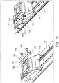
- Figs.2a and 2f the slide rail 207a is shown being inserted into the support rail 205a during mounting of the central seat 207 in the motor vehicle 1.
- An end stop 225 is provided on each support rail 205a, 206a to assist with positioning of the slide rails 207a in the support rails 205a, 206a.
- Fig.2b the position of the slide rail 207a is shown when the central seat 207 is in a normal seating position.
- the slide rails 207a abut against the end stops 225, the pair of latch pins 220 are fully engaged with the detents 230 and the central seat 207 is aligned with two outboard seats 205, 206 so as to form a row of seats extending across the motor vehicle 1.
- Fig.2c the right hand side outboard seat 205 has been moved forwards in the direction of arrow "F" to a rear access position in which it has been slid forward with respect to the central seat 207 and the left hand side outboard seat 206 both of which remain in their normal seating positions.
- the backrest 202 of the right hand side outboard seat 205 is folded forward so as to lie flat on the seat base 203 thereby releasing the latch pin 220 engaged with the detent 230 in the slide rail 207a on the right hand side of the seat base 209 of the central seat 207.
- the seat pedestal 215 is then partially unlatched so as to permit the right hand side outboard seat 205 to be slid forward.
- left hand side outboard seat 206 can be moved into a rear access position in a similar manner while the central seat 207 and the right hand side outboard seat 205 remain in their normal seating positions.
- the central seat 207 is removable from the seating arrangement 200 by folding forward both of the backrests 202, 212 of the outboard seats 205, 206 so that each backrest 202, 212 lies flat upon the respective seat base 203, 213 of the outboard seat 205, 206 of which it forms a part.
- the folding forward of the backrests 202, 212 has the effect of releasing the latching mechanism of the slide mechanism thereby withdrawing the latch pins 220 from the detents 230.
- the releasing of the latching mechanism allows the central seat 207 to be slid out n a rearward direction from between the two outboard seats 205, 206.
- One advantage of providing a sliding interconnection between the two outboard seats 205, 206 and the central seat 207 is that it allows either of the outboard seats 205, 206 to be moved forward to provide better access to a further row of seats to the rear of the seating arrangement 200 without requiring all of the seats 205, 206, 207 forming the motor vehicle seating arrangement 200 to be moved. It will be appreciated that it is a far easier task to move one seat rather than three.
- the motor vehicle seating arrangement 200 can be used with advantage as a front row of seats.
- central seat could be replaced by an alternative item of utility for use by occupants of the motor vehicle such as for example and without limitation, a child seat, a table, an entertainment centre, a storage box and a storage locker.
- the item of utility would be slidingly supported by the two outboard seats in a similar manner to that described with respect to the central seat 207 so as to provide the additional storage under the item of utility while permitting one or other of the outboard seats to be slid forward to provide improved rear access.
- a third embodiment of a motor vehicle seating arrangement which is in some respects the same as the first and second embodiments previously described in that it comprises a pair of outboard seats between which is supported an item of utility in the form of a central seat.
- the motor vehicle seating arrangement 300 comprises a right hand side outboard seat 305, a left hand side outboard seat 306 and a central seat 307 that is located in a gap between the pair of outboard seats 305, 306. It will be appreciated that the seats 305, 306, 307 as shown in Fig.3a face towards a front of the motor vehicle in which they are fitted and are shown without upholstery.
- the right hand side outboard seat 305 has a backrest 302 and a seat base 303 and is mounted on a floor of a motor vehicle via a seat pedestal 315.
- the seat pedestal 315 is moveably mounted on the floor 10 so as to be selectively slideable in a fore-aft direction of the motor vehicle. That is to say, the seat pedestal 315 can be slid forwards or rearwards relative to the floor of the motor vehicle.
- a release lever (the release action of which is indicated by the winged arrow 5 overlying the pedestal 315) is provided on the seat pedestal 315 to release floor latches (not shown) used to hold the seat pedestal 315 in position on the floor. By fully releasing the floor latches the seat pedestal 315 and the associated seat 305 can be removed from the motor vehicle.
- the left hand side outboard seat 306 has a backrest 312 and a seat base 313 and is mounted on the floor of the motor vehicle via a seat pedestal 316.
- the seat pedestal 316 is moveably mounted on the floor so as to be selectively moveable in a fore-aft direction of the motor vehicle. That is to say, the seat pedestal 316 can be slid forwards or rearwards relative to the floor of the motor vehicle.
- a release lever (the release action of which is indicated by the winged arrow 5 overlying the pedestal 316) is provided on the seat pedestal 316 to release floor latches (not shown) used to hold the seat pedestal 316 in position on the floor. By fully releasing the floor latches the seat pedestal 316 and the associated seat 306 can be removed from the motor vehicle.
- the central seat 307 has a backrest 308 and a seat base 309 and is supported by the two outboard seats 305, 306, that is to say, it is a 'suspended seat' as there is no seat pedestal supporting the central seat 307.
- the suspended seat arrangement of the third embodiment has the same advantages referred to with respect to the first and second embodiments of reduced weight and unobstructed space under the central seat 307 due to the lack of a seat pedestal.
- a pair of seat support members in the form of slide rails 307a are fastened to the seat base 309 for engagement with a pair of "U" shaped support rails 305a fastened to the seat bases 303, 313 of the right and left hand side outboard seats 305 and 306 respectively.
- a left hand slide rail 307a fastened to a left hand side of the seat base 309 for engagement with a support rail 305a fastened to a right hand side of the seat base 313 of the left hand side outboard seat 306 and a right hand slide rail 307a fastened to a right hand side of the seat base 309 for engagement with a support rail 305a fastened to a left hand side of the seat base 303 of the right hand side outboard seat 306.
- the central seat 307 is therefore slidingly connected to the pair of outboard seats 305, 306 via a pair of slide mechanisms.
- a latching mechanism (not shown in detail) having a pair of spring biased latch pins 320 each of which is engageable with a respective detent 330 in the pair of slide rails 307a and is used to hold the central seat 307 in position when it is in a normal use position.
- both ends of the slide rails 307a are tapered so that the slide rails 307a can be inserted from the front (see Fig.3c ) or from the rear (see Fig3b ).
- the latch pins 320 have a tapered end with two inclined faces so that the detents 330 in the slide rails 307a can be engaged with the latch pins 320 without the need to operate the release mechanism for the latching mechanism.
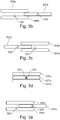
- Fig.3b the slide rail 307a is shown being inserted into the support rail 305a from the rear during mounting of the central seat 307 in the motor vehicle 1.
- the tapered ends of the slide rails 307a will react against the inclined faces of the latch pins 320 thereby pushing the latch pins 320 out of the way until they can engage with the detents 330.
- Fig.3c which is an alternative to Fig.3b , the slide rail 307a is shown being inserted into the support rail 305a from the front during mounting of the central seat 307 in the motor vehicle 1.
- the tapered ends of the slide rails 307a will react against the inclined faces of the latch pins 320 thereby pushing the latch pins 320 out of the way until they can engage with the detents 330.
- Fig.3d the position of the slide rail 307a is shown when the central seat 307 is in a normal seating position in which the pair of latch pins 320 are fully engaged with the detents 330 in the slide rails 305a and the central seat 307 is aligned with two outboard seats 305, 306 so as to form a row of seats extending across the motor vehicle.
- the central seat 307 is removable from the seating arrangement 300 by folding forward both of the backrests 302, 312 of the outboard seats 305, 306 by circa 45 degrees as indicated by the arrows 1 to the positions 302a and 312a, the central seat 307 can then be slid out in a forward or rearward direction as indicated by the double headed arrow 2, the backrest 302, 312 can then be returned to their normal positions as indicated by the arrows 3.
- the folding forward of the backrests 302, 312 has the effect of releasing the latching mechanisms of the slide mechanisms thereby withdrawing the latch pins 320 from the detents 330 which allows the central seat 307 to be slid out from between the two outboard seats 305, 306.
- Fig.3a Also shown in Fig.3a are the arrow 4 and the winged arrow 5 on the pedestal 316 these represent the actions required to move the left hand side outboard seat 306 to a rear access position in which it is slid forward with respect to the central seat 307 and the right hand side outboard seat 305 both of which remain in their normal seating positions. In this position improved access to an area to the rear of the left hand side outboard seat 306 is provided.
- the backrest 312 of the left hand side outboard seat 306 is folded forward by circa 45 degrees from the normal use position as indicated by the arrow 4 to the position 312a thereby releasing the latch pin 320 engaged with the detent 330 in the slide rail 307a on the left hand side of the seat base 309 of the central seat 307.
- the seat pedestal 315 is then partially unlatched by moving the release lever in the direction of the winged arrow 5 on the pedestal 316 so as to permit the left hand side outboard seat 306 to be slid forward.
- one advantage of providing a sliding interconnection between the two outboard seats 305, 306 and the central seat 307 is that it allows either of the outboard seats 305, 306 to be moved forward to provide better access to a further row of seats to the rear of the seating arrangement 300 without requiring all of the seats 305, 306, 307 forming the motor vehicle seating arrangement 300 to be moved. It will be appreciated that it is a far easier task to move one seat rather than three.
- the motor vehicle seating arrangement 300 can be used with advantage as a front row of seats.
- central seat could be replaced by an alternative item of utility for use by occupants of the motor vehicle such as for example, a child seat, a table, an entertainment centre, a storage box and a storage locker.
- the item of utility would be slidingly supported by the two outboard seats in a similar manner to that described with respect to the central seat 307 so as to provide the additional storage under the item of utility while permitting one or other of the outboard seats to be slid forward to provide improved rear access.
- a fourth embodiment of a motor vehicle seating arrangement which is in some respects the same as the other embodiments previously described in that it comprises a pair of outboard seats between which is supported an item of utility in the form of a central seat.
- the motor vehicle seating arrangement 400 comprises a right hand side outboard seat 405, a left hand side outboard seat 406 and a central seat 407 that is located in a gap defined between the pair of outboard seats 405, 406. It will be appreciated that the seats 405, 406, 407 as shown in Figs.4a and 4b face towards a front of the motor vehicle in which they are fitted.
- the right hand side outboard seat 405 has a backrest 402 and a seat base 403 and is mounted on a floor of a motor vehicle such as the floor 10 of the motor vehicle 1 shown in Fig.5 via a seat pedestal 415.
- the seat pedestal 415 is moveably mounted on the floor 10 so as to be selectively slideable in a fore-aft direction of the motor vehicle 1. That is to say, the seat pedestal 415 can be slid forwards or rearwards relative to the floor 10 of the motor vehicle 1.
- a release lever 417 is provided on the seat pedestal 415 to release floor latches (not shown) used to hold the seat pedestal 415 in position on the floor 10. By partially releasing the floor latches the seat pedestal 415 and the associated seat 405 can be slid forwards and rearwards and, by moving the lever 417 to a fully released position, the floor latches are fully released and seat 405 can be removed from the motor vehicle 1.
- the left hand side outboard seat 406 has a backrest 412 and a seat base 413 and is mounted on the floor 10 of the motor vehicle 1 via a seat pedestal 416.
- the seat pedestal 416 is moveably mounted on the floor 10 so as to be selectively moveable in a fore-aft direction of the motor vehicle 1. That is to say, the seat pedestal 416 can be slid forwards or rearwards relative to the floor 10 of the motor vehicle 1.
- a release lever 418 is provided on the seat pedestal 416 to release floor latches (not shown) used to hold the seat pedestal 416 in position on the floor 10. By partially releasing the floor latches the seat pedestal 416 can be slid forwards and rearwards and moving the lever 418 to a fully released position fully releases the floor latches and the seat 406 can then be removed from the motor vehicle 1.
- the central seat 407 has a backrest 408 and a seat base 409 and is supported by the two outboard seats 405, 406 and is therefore a 'suspended seat' as there is no seat pedestal supporting the central seat 407.
- the suspended seat arrangement of this embodiment has the same advantages referred to with respect to the previous embodiments of reduced weight and unobstructed space under the central seat 407 due to the lack of a seat pedestal.
- each seat support member in the form of detents 420 formed in pairs in left and right hand side structures of the seat base 409 respectively are arranged for engagement by two pairs of locking bolts 430 slidingly supported by the left hand side structure of the seat base 403 of the right hand side outboard seat 405 and a pair of locking bolts 430 slidingly supported by the right hand side structure of the seat base 413 of the left hand side outboard seat 406.
- a release mechanism (not shown) is used to retract the bolts 430 into the position shown in Fig.4a when the two backrests 402, 412 are folded forward by a predefined angle which, in the case of Fig.4a , is angle such that the backrests 402, 412 lie upon the seat bases 403, 413.
- the central seat 407 can be inserted or removed from the gap between the pair of outboard seats 405, 406 by lowering it into place in the gap or lifting it out of the gap. It will be appreciated that in practice end stops or guides are provided to assist with the alignment of the bolts 430 with the detents 420.
- the fourth embodiment has the advantage of providing additional storage space under the central seat 407 as per the other embodiments but is inferior to the previous embodiments in that all three seats 405, 406, 407 have to be slid forward to provide improved rear access.
- the fourth embodiment is however of a less complicated construction and so is more economical to manufacture.
- the latches for both of the pedestals 415, 416 have to be released by operation of the lever 417, 418 to allow the three seats 405, 406, 407 to be slid forward from their normal seating positions.
- the motor vehicle seating arrangement 400 could be used as a front row of seats.
- the central seat could be replaced by an alternative item of utility for use by occupants of the motor vehicle such as for example, a child seat, a table, an entertainment centre, a storage box and a storage locker.
- the item of utility would be supported by the two outboard seats in a similar manner to that described above with respect to the central seat 407 so as to provide the additional storage under the item of utility.
Landscapes
- Engineering & Computer Science (AREA)
- Mechanical Engineering (AREA)
- Transportation (AREA)
- Aviation & Aerospace Engineering (AREA)
- Health & Medical Sciences (AREA)
- Child & Adolescent Psychology (AREA)
- General Health & Medical Sciences (AREA)
- Physics & Mathematics (AREA)
- Thermal Sciences (AREA)
- Seats For Vehicles (AREA)
Abstract
Description
- This invention relates to motor vehicles and in particular to a motor vehicle seating arrangement having improved utility.
- It is well known to provide a motor vehicle with two or more rows of seats for use by occupants of the motor vehicle. Particularly in the case of small commercial vehicles having passenger seating such as minibuses and for multi-purpose vehicles (MPVs) there is an increasing need to offer a high level of seating flexibility such as fore-aft movement of the seating and removal of one or more rows of seating.
- However, such seats are often heavy (circa 30kg) due to the need to provide in many cases integral three point safety restraint anchorage points and the consequential need for substantial floor mounting structures sometimes referred to as a "seat leg" or a "seat pedestal".
- The removal of such known seats for the purpose of loading long items is therefore difficult to achieve within the confines of a motor vehicle and so there is a need to provide a seat that is of lighter weight and so is easier to handle.
- In addition, to the foregoing there is an increased need to provide an item of utility for use by occupants of the motor vehicle such as for example, a table, an entertainment centre, a storage bin, a storage locker and a need for increased in-vehicle storage particularly of long items.
- It is an object of this invention to provide a motor vehicle satisfying the aforementioned needs in a cost effective manner.
- According to a first aspect of the invention there is provided a motor vehicle seating arrangement comprising a pair of outboard seats spaced apart to define therebetween a gap into which an item of utility is fitted wherein the item of utility is supported solely by the two outboard seats.
- The item of utility may be supported on a left hand side by a left hand side one of the pair of outboard seats. In which case, the item of utility may advantageously be slidingly supported on the left hand side by a sliding connection with the left hand side one of the pair of outboard seats.
- The item of utility may be supported on a right hand side by a right hand side one of the pair of outboard seats. In which case, the item of utility may advantageously be slidingly supported on a right hand side by a sliding connection with the right hand side one of the pair of outboard seats.
- The item of utility may be a central seat.
- The central seat may have a backrest and a seat base by which it is supported.
- The seat base of the central seat may be mounted on a seat support member and the seat support member may have a pair of recesses on a left hand side used to connect the seat support member on the left hand side to a pair of support pins forming part of a slide mechanism located on the left hand side one of the pair of outboard seats.
- The slide mechanism located on the left hand side one of the pair of outboard seats may be fastened to a seat pedestal of the left hand side one of the pair of outboard seats.
- The seat base of the central seat may be mounted on a seat support member and the seat support member may have a pair of recesses on a right hand side used to connect the seat support member on the right hand side to a pair of support pins forming part of a slide mechanism located on the right hand side one of the pair of outboard seats.
- The slide mechanism located on the right hand side one of the pair of outboard seats may be fastened to a seat pedestal of the right hand side one of the pair of outboard seats.
- Each of the outboard seats may have a backrest, a seat base and a seat pedestal for mounting the respective seat on a floor of a motor vehicle.
- Each of the seat pedestals may include a floor latch mechanism and, when the floor latch mechanism is fully released, the respective seat of which the pedestal forms a part may be removable from the motor vehicle.
- When the floor latch mechanism is partially released the respective seat of which the pedestal forms a part may be slideable in a fore-aft direction of the motor vehicle.
- The item of utility may be one of a child seat, a table, a storage box, a storage locker and an entertainment centre.
- According to a second aspect of the invention there is provided a motor vehicle having a motor vehicle seating arrangement constructed in accordance with said first aspect of the invention.
- The motor vehicle seating arrangement may be a second row seating arrangement.
- The invention will now be described by way of example with reference to the accompanying drawing of which:-
-
Fig.1a is a front left hand perspective view of a first embodiment of a motor vehicle seating arrangement in accordance with the invention showing the seats of the motor vehicle seating arrangement in a normal seating position in which all of the seats making up the motor vehicle seating arrangement are aligned with one another; -
Fig.1b is a front right hand perspective view of support structures forming part of the motor vehicle seating arrangement shown inFig.1a ; -
Fig.1c is a front left hand side perspective view on an enlarged scale of a right hand side outboard seat forming part of the motor vehicle seating arrangement shown inFig.1a ; -
Fig.1d is a front left hand perspective view of the right hand side outboard seat shown inFigs.1a and1c showing the right hand side outboard seat in a rear access position and with the other seats removed so as to more clearly view the seat support structures' -
Fig.1e is a rear right hand side perspective view of the seating arrangement ofFig.1a showing the right hand seat in the rear access position shown inFig.1d ; -
Fig.1f is a schematic plan view showing the spacing of the right hand side outboard seat when in the normal seating position with reference to a rear edge of a side door aperture; -
Fig.1g is a schematic plan view similar toFig.1f but showing the spacing of the right hand side outboard seat when in the rear access position ofFigs.1d and 1e with reference to the rear edge of the side door aperture; -
Fig.1h is a left hand perspective view as viewed from above showing the seats in an un-upholstered form with the right hand side outboard seat in the rear access position; -
Fig.1i is a schematic showing various operational positions of the left hand side outboard seat; -
Fig.2a is a diagrammatic side view of support parts of a second embodiment of a motor vehicle seating arrangement in accordance with the invention showing a right hand slide rail of a central seat being inserted from the rear into a left hand side support rail of a right hand side outboard seat; -
Fig.2b is a diagrammatic side view similar toFig.2a but showing the right hand slide rail of the central seat located and latched in the left hand side support rail of the right hand side outboard seat in a normal latched seating position; -
Fig.2c is a diagrammatic side view similar toFigs.2a and 2b but showing the arrangement of the right hand slide rail of the central seat and the left hand side support rail of the right hand side outboard seat when the right hand side outboard seat has been moved forward into a rear access position; -
Fig.2d is a front perspective view of the motor vehicle seating arrangement in accordance with the second embodiment shown diagrammatically inFigs.2a to 2c prior to engagement of left and right hand slide rails on the central seat with left and right hand side support rails on the right and left hand side outboard seats respectively showing the structure of the seats; -
Fig.2e is a view similar toFig.2d shown the central seat in position between the right and left hand side outboard seats with the central seat unlatched prior to removal of the central seat from its normal in use position; -
Fig.2f is a schematic pictorial view corresponding toFig.2a showing the right hand slide rail of the central seat prior to insertion into the left hand side support rail of the right hand side outboard seat; -
Fig.3a is a front left hand perspective view showing only the structure of the seats forming a third embodiment of a motor vehicle seating arrangement in accordance with the invention showing the seats in a normal seating position in which all of the seats making up the seating arrangement are aligned with one another and indicating the position that backrests of the right hand and left hand side outboard seats are moved to in order to release a central seat; -
Fig.3b is a diagrammatic side view of support parts of the third embodiment of a motor vehicle seating arrangement shown inFig.3a showing a right hand slide rail of the central seat being inserted from the rear into a left hand side support rail of the right hand side outboard seat; -
Fig.3c is a diagrammatic side view of support parts of the third embodiment of a motor vehicle seating arrangement shown inFig.3a showing an alternative to the assembly step ofFig.3b in which the right hand slide rail of the central seat is being inserted from the front into the left hand side support rail of the right hand side outboard seat; -
Fig.3d is a diagrammatic side view similar toFigs.3b and 3c but showing the right hand slide rail of the central seat located and latched in the left hand side support rail of the right hand side outboard seat in the normal seating position; -
Fig.3e is a diagrammatic side view similar toFigs.3b to 3d but showing the arrangement of the right hand slide rail of the central seat and the left hand side support rail of the right hand side outboard seat when the right hand side outboard seat has been moved forward into a rear access position; -
Fig.3f is a schematic front view of the seating arrangement shown inFig.3a showing the manner in which the central seat is slidingly supported by the outboard seats; -
Fig.4a is a diagrammatic front view of a fourth embodiment of a motor vehicle seating arrangement in accordance with the invention showing the insertion of a central seat between right and left hand side outboard seats with backrests of the outboard seats folded forward; -
Fig.4b is a diagrammatic front view of the fourth embodiment of a motor vehicle seating arrangement shown inFig.4a showing the central seat located between the right and left hand side outboard seats in a normal seating position; and -
Fig.5 is a side view of a motor vehicle showing a motor vehicle seating arrangement in accordance with the invention mounted in a passenger compartment of the motor vehicle. - With reference to
Fig.5 amotor vehicle 1 has aside door aperture 2 to provide access to apassenger compartment 3 of themotor vehicle 1 in which is mounted a motorvehicle seating arrangement 50 of a type conforming to the requirements of this invention as set out in the accompanying claims that is to say the motorvehicle seating arrangement 50 has an item of utility in the form of a suspended central seat supported by a pair of outboard seats. - In the case of the example shown in
Fig.5 the motorvehicle seating arrangement 50 is in the form of a second row of seating and is mounted on afloor 10 of themotor vehicle 1 so as be positioned in front of a third row of seating 7 (shown in dotted outline). - The motor
vehicle seating arrangement 50 is mounted so as to be positioned between a front upright 5 and a rear upright 6 which define front and rear edges of theside door aperture 2. -
Further embodiments 100; 200; 300 and 400 of motor vehicle seating arrangements suitable for use in place of theseating arrangement 50 are described hereinafter. - With reference to
Figs.1a to 1i there is shown a first embodiment of a motorvehicle seating arrangement 100. - The
seating arrangement 100 comprises of a right handside outboard seat 105, a left handside outboard seat 106 and an item of utility for use by occupants of the motor vehicle in the form of acentral seat 107 that is located in a gap defined between the pair ofoutboard seats seats - The right hand
side outboard seat 105 has abackrest 102 and aseat base 103 and is mounted on a floor of a motor vehicle such as thefloor 10 of themotor vehicle 1 shown inFig.5 via aseat pedestal 115. - The
seat pedestal 115 is moveably mounted on thefloor 10 so as to be selectively slideable in a fore-aft direction of the motor vehicle 1 (see arrow F-A onFig.1c ). That is to say, theseat pedestal 115 can be slid forwards or rearwards relative to thefloor 10 of themotor vehicle 1. Arelease lever 117 is provided on theseat pedestal 115 to release floor latches (not shown) used to hold theseat pedestal 115 in position on thefloor 10. By releasing these floor latches theseat pedestal 115 and the associatedseat 105 can be removed from themotor vehicle 1. - The left hand
side outboard seat 106 has abackrest 112 and aseat base 113 and is mounted on thefloor 10 of themotor vehicle 1 via aseat pedestal 116. Theseat pedestal 116 is moveably mounted on thefloor 10 so as to be selectively moveable in a fore-aft direction of themotor vehicle 1. That is to say, theseat pedestal 116 can be slid forwards or rearwards relative to thefloor 10 of themotor vehicle 1. Arelease lever 118 is provided on theseat pedestal 116 to release floor latches (not shown) used to hold theseat pedestal 116 in position on thefloor 10. By releasing these floor latches theseat pedestal 116 and the associatedseat 106 can be removed from themotor vehicle 1. - The
central seat 107 has abackrest 108 and aseat base 109 and is supported by the twooutboard seats central seat 107. This has two primary advantages, firstly, there is a significant weight reduction due to the lack of a seat pedestal and secondly, the space normally occupied by the seat pedestal provides additional storage space and allows long objects to pass under thecentral seat 107 of theseating arrangement 100 without hindrance from a seat pedestal. - In order to support the central seat 107 a
seat support member 120 is fitted under theseat base 109 of thecentral seat 107. Theseat support member 120 has a pair of spaced apart recesses on each longitudinal side that engage with support pins 125, 126 attached to arespective carriage carriages seat pedestals slide arms brackets - Therefore the
central seat 107 is slidingly connected to the pair ofoutboard seats central seat 107 in position on the foursupport pins release lever 121 is mounted on theseat support member 120 to selectively release the latching mechanism. - The
central seat 107 is removable from theseating arrangement 100 by using therelease lever 121 to release the latching mechanism and then by lifting thecentral seat 107 out from between the twooutboard seats - It will be appreciated that the support pins 125, 126 can be arranged to be retracted or folded away when the
central seat 107 is removed so as to provide an unobstructed passage between the twooutboard seats - It will be further appreciated that the two support pins could be fixed to the
seat support member 120 for engagement with recesses in the slide mechanisms associated with the outboard seats 105,106. - One of the advantages of providing a sliding interconnection between the two
outboard seats central seat 107 is that it allows either of theoutboard seats seating arrangement 100. - In
Figs.1d, 1e ,1g and1h the right hand side outboardseat 105 is shown in a rear access position in which therespective seat pedestal 115 has been released and the seat pedestal along with the right hand outboardseat 105 has been slid towards a front end of themotor vehicle 1. - In
Fig.1a the motor vehicle seating arrangement is shown in a normal seating position with all threeseats motor vehicle 1. - In
Fig.1f the seats are in the same position as forFig.1a but thebackrest 102 of the right hand side outboardseat 105 has been folded forward to a release position in which the righthand side seat 105 and its associated pedestal can be slid forward. - As can best be seen with reference to
Figs.1f and 1g when the right hand side outboardseat 105 is in the normal seating position a gap 'G1' is provided between therespective seat 105 and arear upright 6 of a door aperture of width 'X' defined between therear upright 6 and afront upright 5. - However, when the right hand side outboard
seat 105 is moved to a rear access position as shown inFig.1g , the gap is increased to width 'G2' due to the forward movement of the right hand side outboardseat 105. - It will be noted that one advantage is that the
central seat 107 and the left hand side outboardseat 106 do not need to be moved to provide this additional room for entry or egress from themotor vehicle 1. - In the case of the embodiment described it will be appreciated that the left hand side outboard
seat 106 can be moved in a similar manner so that improved rear seat access can be provided on both sides of themotor vehicle 1. In such a case thecentral seat 107 and the right hand side outboardseat 105 are not moved from their normal seating positions only the left hand side outboardseat 106 is moved. - It will be further appreciated that in an alternative embodiment not shown, one side of the central seat can be slidingly attached to one of the two outboard seats and the other side can be releasably connected to the other of the two outboard seats such that no relative fore-aft movement is provided between the central seat and the other of the two outboard seats.
- With such an arrangement improved rear seat access would be provided by sliding forward the one outboard seat slidingly connected to the central seat with the other two seats remaining in the same position. However, improved rear access is only provided on one side of the motor vehicle with such an arrangement.
- With particular reference to
Fig.1i various operational positions of the right hand side outboardseat 105 are shown. It will be appreciated that the same operational positions and functionality is present on the left hand side outboardseat 106. - When the
backrest 102 of the right hand side outboardseat 105 is in the position 102(a) all of the various latches are in their respective fully latched states and therespective seat 105 is in a normal use seating state. - When the
backrest 102 is in the position 102(b) in which it has been folded forward circa 45 degrees from a normal upright position indicated by the reference numeral 102(a), the latches holding theseat pedestal 115 to thefloor 10 are released so as to permit forward and rearward sliding movement of theseat pedestal 115 and the associatedseat 105 relative to thefloor 10 and a slide latch (not shown) associated with the slide mechanism are released allowing relative movement between theslide arms - When the
backrest 102 is in the position 102(c) in which it has been folded forward circa 125 degrees from the normal upright position indicated by the reference numeral 102(a) so as to lie flat upon theseat base 103 and the latches holding theseat pedestal 115 to thefloor 10 are engaged so as to prevent forward and rearward movement of theseat pedestal 115 and the associatedseat 105 relative to thefloor 10 and the slide latch associated with the slide mechanism is latched so as to prevent relative movement between theslide arms - Irrespective of the position of the
seat backrest 102 if therelease lever 117 provided on theseat pedestal 115 is moved to a release position as indicated by the arrow 117(d) then this will fully release the associated floor latches thereby allowing the right hand side outboardseat 105 and the associatedpedestal 115 to be removed from themotor vehicle 1. - Therefore in summary, by suspending the
central seat 107 between the twooutboard seats central seat 107 is considerably reduced due to the absence of a seat pedestal and a large storage space is provided under thecentral seat 107. By using sliding connections between thecentral seat 107 and the twooutboard seats outboard seats Fig.5 ) located behind the motorvehicle seating arrangement 100 which forms second row seating in the case of this example. - It will be appreciated that in the case of a motor vehicle having only two rows of seats the motor
vehicle seating arrangement 100 could be used with advantage as a front row of seats. - It will also be appreciated that the central seat could be replaced by an alternative item of utility for use by occupants of the motor vehicle such as for example, a child seat assembly, a table, an entertainment centre, a storage box and a storage locker.
- In such a case the item of utility would be slidingly supported by the two outboard seats in a similar manner to that described so as to provide the additional storage under the item of utility while permitting either one of the outboard seats to be slid forward to provide improved rear access.
- With reference to
Figs.2a to 2f there is shown a second embodiment of a motor vehicle seating arrangement which is in some respects the same as the first embodiment previously described in that it comprises a pair of outboard seats between which is supported an item of utility in the form of a central seat. - The motor
vehicle seating arrangement 200 comprises a right hand side outboardseat 205, a left hand side outboardseat 206 and acentral seat 207 that is located in a gap defined between the pair ofoutboard seats seats Figs.2d and 2e face towards a front of the motor vehicle in which they are fitted and are shown without upholstery. - The right hand side outboard
seat 205 has abackrest 202 and aseat base 203 and is mounted on a floor of a motor vehicle such as thefloor 10 of themotor vehicle 1 shown inFig.5 via aseat pedestal 215. - The
seat pedestal 215 is moveably mounted on thefloor 10 so as to be selectively slideable in a fore-aft direction of themotor vehicle 1. That is to say, theseat pedestal 215 can be slid forwards or rearwards relative to thefloor 10 of themotor vehicle 1. A release lever (not shown) is provided on theseat pedestal 215 to release floor latches (not shown) used to hold theseat pedestal 215 in position on thefloor 10. By fully releasing the floor latches theseat pedestal 215 and the associatedseat 205 can be removed from themotor vehicle 1. - The left hand side outboard
seat 206 has abackrest 212 and aseat base 213 and is mounted on thefloor 10 of themotor vehicle 1 via aseat pedestal 216. Theseat pedestal 216 is moveably mounted on thefloor 10 so as to be selectively moveable in a fore-aft direction of themotor vehicle 1. That is to say, theseat pedestal 216 can be slid forwards or rearwards relative to thefloor 10 of themotor vehicle 1. A release lever (not shown) is provided on theseat pedestal 216 to release floor latches (not shown) used to hold theseat pedestal 216 in position on thefloor 10. By fully releasing the floor latches theseat pedestal 216 and the associatedseat 206 can be removed from themotor vehicle 1. - The
central seat 207 has abackrest 208 and aseat base 209 and is supported by the twooutboard seats central seat 207. - The use of a suspended seat arrangement for the second embodiment has the same advantages referred to with respect to the first embodiment of reduced weight and unobstructed space under the
central seat 207 due to the lack of a seat pedestal. - In order to support the
central seat 207 a pair of seat support members in the form ofslide rails 207a are fastened to theseat base 209 for engagement with a pair of "U" shapedsupport rails outboard seats - It will be appreciated that there is a left
hand slide rail 207a fastened to a left hand side of theseat base 209 for engagement with asupport rail 206a fastened to a right hand side of theseat base 213 of the left hand side outboardseat 206 and a righthand slide rail 207a fastened to a right hand side of theseat base 209 for engagement with asupport rail 205a fastened to a left hand side of theseat base 203 of the right hand side outboardseat 206. - The
central seat 207 is therefore slidingly supported by the pair ofoutboard seats respective detent 230 in the pair ofslide rails 207a and is used to hold thecentral seat 207 in position when it is in a normal use position. Note that the end of theslide rails 207a are tapered and that the latch pins 220 have an angled face so that thedetents 230 in theslide rails 207a can be engaged with the latch pins 220 without the need to operate the release mechanism for the latching mechanism although the latching mechanism has to be released to remove thecentral seat 207. - In
Fig.2d thecentral seat 207 is shown being lifted into place prior to insertion of the pair ofslide rails 207a with the support rails 205a, 206a, thebackrests - In
Figs.2a and 2f theslide rail 207a is shown being inserted into thesupport rail 205a during mounting of thecentral seat 207 in themotor vehicle 1. Anend stop 225 is provided on eachsupport rail slide rails 207a in the support rails 205a, 206a. - In
Fig.2b the position of theslide rail 207a is shown when thecentral seat 207 is in a normal seating position. In this normal seating position theslide rails 207a abut against the end stops 225, the pair of latch pins 220 are fully engaged with thedetents 230 and thecentral seat 207 is aligned with twooutboard seats motor vehicle 1. - In
Fig.2c the right hand side outboardseat 205 has been moved forwards in the direction of arrow "F" to a rear access position in which it has been slid forward with respect to thecentral seat 207 and the left hand side outboardseat 206 both of which remain in their normal seating positions. In order to move the right hand side outboardseat 205 thebackrest 202 of the right hand side outboardseat 205 is folded forward so as to lie flat on theseat base 203 thereby releasing thelatch pin 220 engaged with thedetent 230 in theslide rail 207a on the right hand side of theseat base 209 of thecentral seat 207. Theseat pedestal 215 is then partially unlatched so as to permit the right hand side outboardseat 205 to be slid forward. - It will be appreciated that the left hand side outboard
seat 206 can be moved into a rear access position in a similar manner while thecentral seat 207 and the right hand side outboardseat 205 remain in their normal seating positions. - As shown in
Fig.2e thecentral seat 207 is removable from theseating arrangement 200 by folding forward both of thebackrests outboard seats backrest respective seat base outboard seat backrests detents 230. The releasing of the latching mechanism allows thecentral seat 207 to be slid out n a rearward direction from between the twooutboard seats - One advantage of providing a sliding interconnection between the two
outboard seats central seat 207 is that it allows either of theoutboard seats seating arrangement 200 without requiring all of theseats vehicle seating arrangement 200 to be moved. It will be appreciated that it is a far easier task to move one seat rather than three. - It will be appreciated that, in the case of a motor vehicle having only two rows of seats, the motor
vehicle seating arrangement 200 can be used with advantage as a front row of seats. - It will also be appreciated that the central seat could be replaced by an alternative item of utility for use by occupants of the motor vehicle such as for example and without limitation, a child seat, a table, an entertainment centre, a storage box and a storage locker.
- In such a case the item of utility would be slidingly supported by the two outboard seats in a similar manner to that described with respect to the
central seat 207 so as to provide the additional storage under the item of utility while permitting one or other of the outboard seats to be slid forward to provide improved rear access. - With reference to
Figs.3a to 3e there is shown a third embodiment of a motor vehicle seating arrangement which is in some respects the same as the first and second embodiments previously described in that it comprises a pair of outboard seats between which is supported an item of utility in the form of a central seat. - The motor
vehicle seating arrangement 300 comprises a right hand side outboardseat 305, a left hand side outboardseat 306 and acentral seat 307 that is located in a gap between the pair ofoutboard seats seats Fig.3a face towards a front of the motor vehicle in which they are fitted and are shown without upholstery. - The right hand side outboard
seat 305 has abackrest 302 and aseat base 303 and is mounted on a floor of a motor vehicle via aseat pedestal 315. - The
seat pedestal 315 is moveably mounted on thefloor 10 so as to be selectively slideable in a fore-aft direction of the motor vehicle. That is to say, theseat pedestal 315 can be slid forwards or rearwards relative to the floor of the motor vehicle. A release lever (the release action of which is indicated by thewinged arrow 5 overlying the pedestal 315) is provided on theseat pedestal 315 to release floor latches (not shown) used to hold theseat pedestal 315 in position on the floor. By fully releasing the floor latches theseat pedestal 315 and the associatedseat 305 can be removed from the motor vehicle. - The left hand side outboard
seat 306 has abackrest 312 and aseat base 313 and is mounted on the floor of the motor vehicle via aseat pedestal 316. Theseat pedestal 316 is moveably mounted on the floor so as to be selectively moveable in a fore-aft direction of the motor vehicle. That is to say, theseat pedestal 316 can be slid forwards or rearwards relative to the floor of the motor vehicle. A release lever (the release action of which is indicated by thewinged arrow 5 overlying the pedestal 316) is provided on theseat pedestal 316 to release floor latches (not shown) used to hold theseat pedestal 316 in position on the floor. By fully releasing the floor latches theseat pedestal 316 and the associatedseat 306 can be removed from the motor vehicle. - The
central seat 307 has abackrest 308 and aseat base 309 and is supported by the twooutboard seats central seat 307. - The suspended seat arrangement of the third embodiment has the same advantages referred to with respect to the first and second embodiments of reduced weight and unobstructed space under the
central seat 307 due to the lack of a seat pedestal. - In order to support the
central seat 307 a pair of seat support members in the form ofslide rails 307a (seeFigs.3b to 3e ) are fastened to theseat base 309 for engagement with a pair of "U" shapedsupport rails 305a fastened to the seat bases 303, 313 of the right and left hand sideoutboard seats - As shown in
Fig.3f there is a lefthand slide rail 307a fastened to a left hand side of theseat base 309 for engagement with asupport rail 305a fastened to a right hand side of theseat base 313 of the left hand side outboardseat 306 and a righthand slide rail 307a fastened to a right hand side of theseat base 309 for engagement with asupport rail 305a fastened to a left hand side of theseat base 303 of the right hand side outboardseat 306. - The
central seat 307 is therefore slidingly connected to the pair ofoutboard seats respective detent 330 in the pair ofslide rails 307a and is used to hold thecentral seat 307 in position when it is in a normal use position. Note that in the case of the third embodiment both ends of theslide rails 307a are tapered so that theslide rails 307a can be inserted from the front (seeFig.3c ) or from the rear (seeFig3b ). The latch pins 320 have a tapered end with two inclined faces so that thedetents 330 in theslide rails 307a can be engaged with the latch pins 320 without the need to operate the release mechanism for the latching mechanism. - In
Fig.3b theslide rail 307a is shown being inserted into thesupport rail 305a from the rear during mounting of thecentral seat 307 in themotor vehicle 1. The tapered ends of theslide rails 307a will react against the inclined faces of the latch pins 320 thereby pushing the latch pins 320 out of the way until they can engage with thedetents 330. - In
Fig.3c which is an alternative toFig.3b , theslide rail 307a is shown being inserted into thesupport rail 305a from the front during mounting of thecentral seat 307 in themotor vehicle 1. As before, the tapered ends of theslide rails 307a will react against the inclined faces of the latch pins 320 thereby pushing the latch pins 320 out of the way until they can engage with thedetents 330. - In
Fig.3d the position of theslide rail 307a is shown when thecentral seat 307 is in a normal seating position in which the pair of latch pins 320 are fully engaged with thedetents 330 in the slide rails 305a and thecentral seat 307 is aligned with twooutboard seats - Referring back to
Fig.3a , thecentral seat 307 is removable from theseating arrangement 300 by folding forward both of thebackrests outboard seats arrows 1 to thepositions central seat 307 can then be slid out in a forward or rearward direction as indicated by the double headedarrow 2, thebackrest arrows 3. - The folding forward of the
backrests detents 330 which allows thecentral seat 307 to be slid out from between the twooutboard seats - Also shown in
Fig.3a are the arrow 4 and thewinged arrow 5 on thepedestal 316 these represent the actions required to move the left hand side outboardseat 306 to a rear access position in which it is slid forward with respect to thecentral seat 307 and the right hand side outboardseat 305 both of which remain in their normal seating positions. In this position improved access to an area to the rear of the left hand side outboardseat 306 is provided. - In order to move the left hand side outboard
seat 306 to the improved rear access position, thebackrest 312 of the left hand side outboardseat 306 is folded forward by circa 45 degrees from the normal use position as indicated by the arrow 4 to theposition 312a thereby releasing thelatch pin 320 engaged with thedetent 330 in theslide rail 307a on the left hand side of theseat base 309 of thecentral seat 307. Theseat pedestal 315 is then partially unlatched by moving the release lever in the direction of thewinged arrow 5 on thepedestal 316 so as to permit the left hand side outboardseat 306 to be slid forward. - It will be appreciated that the right hand side outboard
seat 305 can be moved into an improved rear access position in a similar manner while both thecentral seat 307 and the left hand side outboardseat 306 remain in their normal seating positions. - As before, one advantage of providing a sliding interconnection between the two
outboard seats central seat 307 is that it allows either of theoutboard seats seating arrangement 300 without requiring all of theseats vehicle seating arrangement 300 to be moved. It will be appreciated that it is a far easier task to move one seat rather than three. - As before, in the case of a motor vehicle having only two rows of seats the motor
vehicle seating arrangement 300 can be used with advantage as a front row of seats. - It will also be appreciated that the central seat could be replaced by an alternative item of utility for use by occupants of the motor vehicle such as for example, a child seat, a table, an entertainment centre, a storage box and a storage locker.
- In such a case the item of utility would be slidingly supported by the two outboard seats in a similar manner to that described with respect to the
central seat 307 so as to provide the additional storage under the item of utility while permitting one or other of the outboard seats to be slid forward to provide improved rear access. - With reference to
Figs.4a and4b there is shown a fourth embodiment of a motor vehicle seating arrangement which is in some respects the same as the other embodiments previously described in that it comprises a pair of outboard seats between which is supported an item of utility in the form of a central seat. - The motor
vehicle seating arrangement 400 comprises a right hand side outboardseat 405, a left hand side outboardseat 406 and acentral seat 407 that is located in a gap defined between the pair ofoutboard seats seats Figs.4a and4b face towards a front of the motor vehicle in which they are fitted. - The right hand side outboard
seat 405 has abackrest 402 and aseat base 403 and is mounted on a floor of a motor vehicle such as thefloor 10 of themotor vehicle 1 shown inFig.5 via aseat pedestal 415. - The
seat pedestal 415 is moveably mounted on thefloor 10 so as to be selectively slideable in a fore-aft direction of themotor vehicle 1. That is to say, theseat pedestal 415 can be slid forwards or rearwards relative to thefloor 10 of themotor vehicle 1. - A
release lever 417 is provided on theseat pedestal 415 to release floor latches (not shown) used to hold theseat pedestal 415 in position on thefloor 10. By partially releasing the floor latches theseat pedestal 415 and the associatedseat 405 can be slid forwards and rearwards and, by moving thelever 417 to a fully released position, the floor latches are fully released andseat 405 can be removed from themotor vehicle 1. - The left hand side outboard
seat 406 has abackrest 412 and aseat base 413 and is mounted on thefloor 10 of themotor vehicle 1 via aseat pedestal 416. Theseat pedestal 416 is moveably mounted on thefloor 10 so as to be selectively moveable in a fore-aft direction of themotor vehicle 1. That is to say, theseat pedestal 416 can be slid forwards or rearwards relative to thefloor 10 of themotor vehicle 1. - A
release lever 418 is provided on theseat pedestal 416 to release floor latches (not shown) used to hold theseat pedestal 416 in position on thefloor 10. By partially releasing the floor latches theseat pedestal 416 can be slid forwards and rearwards and moving thelever 418 to a fully released position fully releases the floor latches and theseat 406 can then be removed from themotor vehicle 1. - The
central seat 407 has abackrest 408 and aseat base 409 and is supported by the twooutboard seats central seat 407. The suspended seat arrangement of this embodiment has the same advantages referred to with respect to the previous embodiments of reduced weight and unobstructed space under thecentral seat 407 due to the lack of a seat pedestal. - In order to support the
central seat 407 four seat support members in the form ofdetents 420 formed in pairs in left and right hand side structures of theseat base 409 respectively are arranged for engagement by two pairs of lockingbolts 430 slidingly supported by the left hand side structure of theseat base 403 of the right hand side outboardseat 405 and a pair of lockingbolts 430 slidingly supported by the right hand side structure of theseat base 413 of the left hand side outboardseat 406. - A release mechanism (not shown) is used to retract the
bolts 430 into the position shown inFig.4a when the twobackrests Fig.4a , is angle such that thebackrests - As shown by the double headed arrow S on
Fig.4a thecentral seat 407 can be inserted or removed from the gap between the pair ofoutboard seats bolts 430 with thedetents 420. - As shown in
Fig.4b , when thecentral seat 407 is position, thebackrests bolts 430 to engage with thedetents 420. - The fourth embodiment has the advantage of providing additional storage space under the
central seat 407 as per the other embodiments but is inferior to the previous embodiments in that all threeseats - In order to provide improved rear access the latches for both of the
pedestals lever seats - As before in the case of a motor vehicle having only two rows of seats the motor
vehicle seating arrangement 400 could be used as a front row of seats. - It will also be appreciated that the central seat could be replaced by an alternative item of utility for use by occupants of the motor vehicle such as for example, a child seat, a table, an entertainment centre, a storage box and a storage locker. In such a case the item of utility would be supported by the two outboard seats in a similar manner to that described above with respect to the
central seat 407 so as to provide the additional storage under the item of utility. - It will be appreciated by those skilled in the art that although the invention has been described by way of example with reference to one or more embodiments it is not limited to the disclosed embodiments and that alternative embodiments could be constructed without departing from the scope of the invention as defined by the appended claims.
Claims (15)
- A motor vehicle seating arrangement comprising a pair of outboard seats spaced apart to define therebetween a gap into which an item of utility is fitted wherein the item of utility is supported solely by the two outboard seats.
- A motor vehicle seating arrangement as claimed in claim 1 wherein the item of utility is supported on a left hand side by a left hand side one of the pair of outboard seats.
- A motor vehicle seating arrangement as claimed in claim 2 wherein the item of utility is slidingly supported on the left hand side by a sliding connection with the left hand side one of the pair of outboard seats.
- A motor vehicle seating arrangement as claimed in any of claims 1 to 3 wherein the item of utility is supported on a right hand side by a right hand side one of the pair of outboard seats.
- A motor vehicle seating arrangement as claimed in claim 4 wherein the item of utility is slidingly supported on a right hand side by a sliding connection with the right hand side one of the pair of outboard seats.
- A motor vehicle seating arrangement as claimed in any of claims 1 to 5 wherein the item of utility is a central seat.
- A motor vehicle seating arrangement as claimed in claim 6 wherein the central seat has a backrest and a seat base by which it is supported.
- A motor vehicle seating arrangement as claimed in claim 7 wherein the seat base of the central seat is mounted on a seat support member and the seat support member has a pair of recesses on a left hand side used to connect the seat support member on the left hand side to a pair of support pins forming part of a slide mechanism located on the left hand side one of the pair of outboard seats.
- A motor vehicle seating arrangement as claimed in claim 8 wherein the slide mechanism located on the left hand side one of the pair of outboard seats is fastened to a seat pedestal of the left hand side one of the pair of outboard seats.
- A motor vehicle seating arrangement as claimed in claim 7 wherein the seat base of the central seat is mounted on a seat support member and the seat support member has a pair of recesses on a right hand side used to connect the seat support member on the right hand side to a pair of support pins forming part of a slide mechanism located on the right hand side one of the pair of outboard seats.
- A motor vehicle seating arrangement as claimed in claim 10 wherein the slide mechanism located on the right hand side one of the pair of outboard seats is fastened to a seat pedestal of the right hand side one of the pair of outboard seats.
- A motor vehicle seating arrangement as claimed in any of claims 1 to 11 wherein each of the outboard seats has a backrest, a seat base and a seat pedestal for mounting the respective seat on a floor of a motor vehicle.
- A motor vehicle seating arrangement as claimed in claim 12 wherein each of the seat pedestals includes a floor latch mechanism and, when the floor latch mechanism is fully released, the respective seat of which the pedestal forms a part is removable from the motor vehicle.
- A motor vehicle seating arrangement as claimed in claim 13 wherein when the floor latch mechanism is partially released the respective seat of which the pedestal forms a part is slideable in a fore-aft direction of the motor vehicle.
- A motor vehicle seating arrangement as claimed in any of claims 1 to 5 wherein the item of utility is one of a child seat, a table, a storage box, a storage locker and an entertainment centre.
Applications Claiming Priority (1)
| Application Number | Priority Date | Filing Date | Title |
|---|---|---|---|
| GB1707726.4A GB2562479B (en) | 2017-05-15 | 2017-05-15 | A motor vehicle seating arrangement |
Publications (2)
| Publication Number | Publication Date |
|---|---|
| EP3403874A1 true EP3403874A1 (en) | 2018-11-21 |
| EP3403874B1 EP3403874B1 (en) | 2021-10-27 |
Family
ID=59201650
Family Applications (1)
| Application Number | Title | Priority Date | Filing Date |
|---|---|---|---|
| EP18155499.9A Not-in-force EP3403874B1 (en) | 2017-05-15 | 2018-02-07 | A motor vehicle seating arrangement |
Country Status (4)
| Country | Link |
|---|---|
| US (1) | US10189378B2 (en) |
| EP (1) | EP3403874B1 (en) |
| CN (1) | CN108859877B (en) |
| GB (1) | GB2562479B (en) |
Cited By (2)
| Publication number | Priority date | Publication date | Assignee | Title |
|---|---|---|---|---|
| DE102020117703A1 (en) | 2020-07-06 | 2022-01-13 | Audi Aktiengesellschaft | Mounting arrangement for an additional seat |
| KR20220065469A (en) * | 2020-11-13 | 2022-05-20 | 현대자동차주식회사 | Assembling structure for cushion frame in the seat |
Families Citing this family (7)
| Publication number | Priority date | Publication date | Assignee | Title |
|---|---|---|---|---|
| CN109823237B (en) * | 2019-01-08 | 2020-07-28 | 浙江零跑科技有限公司 | Commercial affairs car seat arrangement structure |
| US12420687B2 (en) * | 2021-05-28 | 2025-09-23 | Lear Corporation | Trim support member |
| KR20240012113A (en) * | 2022-07-20 | 2024-01-29 | 현대자동차주식회사 | Rear seat for vehicle |
| KR20240012114A (en) * | 2022-07-20 | 2024-01-29 | 현대자동차주식회사 | Rear seat for vehicle |
| KR20240027458A (en) * | 2022-08-23 | 2024-03-04 | 현대자동차주식회사 | Rear seat for vehicle |
| CN115742891A (en) * | 2022-11-24 | 2023-03-07 | 江铃汽车股份有限公司 | Variable space seat in car and MPV motorcycle type vehicle |
| EP4743330A1 (en) * | 2023-07-14 | 2026-05-20 | Via Fortuna, LLC | DEVICES, SYSTEMS AND METHODS FOR MOTOR VEHICLE SEATS AND MOTOR VEHICLE SEAT ARRANGEMENTS |
Citations (4)
| Publication number | Priority date | Publication date | Assignee | Title |
|---|---|---|---|---|
| DE102008029261A1 (en) * | 2008-06-19 | 2009-12-24 | GM Global Technology Operations, Inc., Detroit | Seating arrangement for motor vehicle, has two vehicle seats, which are arranged side by side in transverse direction under formation of gap, where backrest part or seat part of auxiliary seat is fixed |
| US20110175411A1 (en) * | 2010-01-20 | 2011-07-21 | Uwe Wagner | Stowable vehicle seat |
| DE102007053958B4 (en) * | 2007-02-26 | 2016-04-28 | Johnson Controls Gmbh | vehicle seat |
| US9352676B1 (en) * | 2015-02-23 | 2016-05-31 | Fca Us Llc | Vehicle seating arrangement |
Family Cites Families (14)
| Publication number | Priority date | Publication date | Assignee | Title |
|---|---|---|---|---|
| US1922502A (en) * | 1930-12-10 | 1933-08-15 | Int Motor Co | Aisle seat for busses |
| US2493806A (en) * | 1947-11-06 | 1950-01-10 | Walter L Dumas | Portable auxiliary seat for automobiles |
| FR2816895B1 (en) * | 2000-11-20 | 2003-03-07 | Peugeot Citroen Automobiles Sa | MOTOR VEHICLE SEAT ASSEMBLY |
| KR20040042946A (en) * | 2002-11-14 | 2004-05-22 | 기아자동차주식회사 | Structure for mounting center seat of vehicle |
| JP4216147B2 (en) * | 2003-02-13 | 2009-01-28 | 本田技研工業株式会社 | Vehicle seat |
| FR2874868B1 (en) * | 2004-09-06 | 2006-12-01 | Grupo Antolin Ingenieria Sa Sa | REMOVABLE SEAT |
| SE530121C2 (en) * | 2005-07-11 | 2008-03-04 | Gm Global Tech Operations Inc | Seat arrangement and method for changing the number of seats in a car |
| FR2903350B1 (en) * | 2006-07-05 | 2008-09-26 | Renault Sas | AUTOMOBILE REAR SEAT HULL |
| US20090258199A1 (en) * | 2008-04-15 | 2009-10-15 | Blue Collar Lacrosse Inc. | Wax impregnated mesh pocket for lacrosse stick and process for producing same |
| US8215695B2 (en) * | 2009-11-09 | 2012-07-10 | Toyota Boshoku Kabushiki Kaisha | Removable vehicle seat |
| US8678497B2 (en) * | 2010-08-30 | 2014-03-25 | Honda Motor Co., Ltd. | Seating arrangement for a vehicle |
| CA2835944C (en) * | 2011-06-23 | 2019-04-09 | Magna Seating Inc. | Stow-in-floor seat assembly |
| US9359079B2 (en) * | 2011-07-11 | 2016-06-07 | Molon Labe Llc | Slider seat for aircraft |
| US8632113B2 (en) * | 2011-09-09 | 2014-01-21 | Chrysler Group Llc | Stowable seat arrangement for a motor vehicle |
-
2017
- 2017-05-15 GB GB1707726.4A patent/GB2562479B/en not_active Expired - Fee Related
-
2018
- 2018-02-07 EP EP18155499.9A patent/EP3403874B1/en not_active Not-in-force
- 2018-03-21 US US15/927,438 patent/US10189378B2/en active Active
- 2018-05-11 CN CN201810450335.1A patent/CN108859877B/en not_active Expired - Fee Related
Patent Citations (4)
| Publication number | Priority date | Publication date | Assignee | Title |
|---|---|---|---|---|
| DE102007053958B4 (en) * | 2007-02-26 | 2016-04-28 | Johnson Controls Gmbh | vehicle seat |
| DE102008029261A1 (en) * | 2008-06-19 | 2009-12-24 | GM Global Technology Operations, Inc., Detroit | Seating arrangement for motor vehicle, has two vehicle seats, which are arranged side by side in transverse direction under formation of gap, where backrest part or seat part of auxiliary seat is fixed |
| US20110175411A1 (en) * | 2010-01-20 | 2011-07-21 | Uwe Wagner | Stowable vehicle seat |
| US9352676B1 (en) * | 2015-02-23 | 2016-05-31 | Fca Us Llc | Vehicle seating arrangement |
Cited By (4)
| Publication number | Priority date | Publication date | Assignee | Title |
|---|---|---|---|---|
| DE102020117703A1 (en) | 2020-07-06 | 2022-01-13 | Audi Aktiengesellschaft | Mounting arrangement for an additional seat |
| DE102020117703B4 (en) | 2020-07-06 | 2023-07-20 | Audi Aktiengesellschaft | Mounting arrangement for an additional seat |
| KR20220065469A (en) * | 2020-11-13 | 2022-05-20 | 현대자동차주식회사 | Assembling structure for cushion frame in the seat |
| US11472324B2 (en) * | 2020-11-13 | 2022-10-18 | Hyundai Motor Company | Combination structure of seat cushion frame |
Also Published As
| Publication number | Publication date |
|---|---|
| US10189378B2 (en) | 2019-01-29 |
| CN108859877A (en) | 2018-11-23 |
| GB2562479A (en) | 2018-11-21 |
| CN108859877B (en) | 2022-05-31 |
| GB2562479B (en) | 2019-11-06 |
| US20180326871A1 (en) | 2018-11-15 |
| GB201707726D0 (en) | 2017-06-28 |
| EP3403874B1 (en) | 2021-10-27 |
Similar Documents
| Publication | Publication Date | Title |
|---|---|---|
| EP3403874B1 (en) | A motor vehicle seating arrangement | |
| US10189373B2 (en) | Seat arrangement | |
| US7510227B2 (en) | Vehicle rear seat | |
| US4194782A (en) | Foldable seat structures for automobiles | |
| JP6255049B2 (en) | Vehicle seat mounting device | |
| US6685269B1 (en) | Vehicle seat assembly | |
| US10946775B2 (en) | Vehicle seat storage system | |
| US20230192201A1 (en) | Vehicle having a moveable bulkhead | |
| US9545858B2 (en) | Back seat arrangement of a passenger car | |
| DE102021116462B4 (en) | VEHICLE SEAT DEVICE | |
| CN112829708B (en) | Wheelchair passenger restraint structure | |
| DE102014203669B4 (en) | LUGGAGE RESTRAINT SYSTEM | |
| US8925888B2 (en) | Seat slide locking apparatus | |
| US7510161B2 (en) | Longitudinal guiding element for motor vehicle seat | |
| DE102012207281B4 (en) | Arrangement of a loading floor element in a luggage compartment of a motor vehicle | |
| JP3456523B2 (en) | Car retractable rear seat | |
| DE10207485B4 (en) | Folding seat for commercial vehicles | |
| GB2293318A (en) | vehicle seat assembly with safety beam | |
| JP2018161924A (en) | Underfloor storage device | |
| CN110789413A (en) | Locking mechanism and contain its car seat | |
| JPH078060U (en) | Vehicle seat structure | |
| JPS637549Y2 (en) | ||
| JPS5911798Y2 (en) | car seat | |
| JP2010018153A (en) | Luggage compartment separator device | |
| JP2000025527A (en) | Car luggage structure |
Legal Events
| Date | Code | Title | Description |
|---|---|---|---|
| PUAI | Public reference made under article 153(3) epc to a published international application that has entered the european phase |
Free format text: ORIGINAL CODE: 0009012 |
|
| STAA | Information on the status of an ep patent application or granted ep patent |
Free format text: STATUS: THE APPLICATION HAS BEEN PUBLISHED |
|
| AK | Designated contracting states |
Kind code of ref document: A1 Designated state(s): AL AT BE BG CH CY CZ DE DK EE ES FI FR GB GR HR HU IE IS IT LI LT LU LV MC MK MT NL NO PL PT RO RS SE SI SK SM TR |
|
| AX | Request for extension of the european patent |
Extension state: BA ME |
|
| STAA | Information on the status of an ep patent application or granted ep patent |
Free format text: STATUS: REQUEST FOR EXAMINATION WAS MADE |
|
| 17P | Request for examination filed |
Effective date: 20181129 |
|
| RBV | Designated contracting states (corrected) |
Designated state(s): AL AT BE BG CH CY CZ DE DK EE ES FI FR GB GR HR HU IE IS IT LI LT LU LV MC MK MT NL NO PL PT RO RS SE SI SK SM TR |
|
| STAA | Information on the status of an ep patent application or granted ep patent |
Free format text: STATUS: EXAMINATION IS IN PROGRESS |
|
| 17Q | First examination report despatched |
Effective date: 20201215 |
|
| GRAP | Despatch of communication of intention to grant a patent |
Free format text: ORIGINAL CODE: EPIDOSNIGR1 |
|
| STAA | Information on the status of an ep patent application or granted ep patent |
Free format text: STATUS: GRANT OF PATENT IS INTENDED |
|
| INTG | Intention to grant announced |
Effective date: 20210528 |
|
| GRAS | Grant fee paid |
Free format text: ORIGINAL CODE: EPIDOSNIGR3 |
|
| GRAA | (expected) grant |
Free format text: ORIGINAL CODE: 0009210 |
|
| STAA | Information on the status of an ep patent application or granted ep patent |
Free format text: STATUS: THE PATENT HAS BEEN GRANTED |
|
| AK | Designated contracting states |
Kind code of ref document: B1 Designated state(s): AL AT BE BG CH CY CZ DE DK EE ES FI FR GB GR HR HU IE IS IT LI LT LU LV MC MK MT NL NO PL PT RO RS SE SI SK SM TR |
|
| REG | Reference to a national code |
Ref country code: GB Ref legal event code: FG4D |
|
| REG | Reference to a national code |
Ref country code: CH Ref legal event code: EP |
|
| REG | Reference to a national code |
Ref country code: AT Ref legal event code: REF Ref document number: 1441494 Country of ref document: AT Kind code of ref document: T Effective date: 20211115 |
|
| REG | Reference to a national code |
Ref country code: DE Ref legal event code: R096 Ref document number: 602018025519 Country of ref document: DE |
|
| REG | Reference to a national code |
Ref country code: IE Ref legal event code: FG4D |
|
| REG | Reference to a national code |
Ref country code: LT Ref legal event code: MG9D |
|
| REG | Reference to a national code |
Ref country code: NL Ref legal event code: MP Effective date: 20211027 |
|
| REG | Reference to a national code |
Ref country code: AT Ref legal event code: MK05 Ref document number: 1441494 Country of ref document: AT Kind code of ref document: T Effective date: 20211027 |
|
| PG25 | Lapsed in a contracting state [announced via postgrant information from national office to epo] |
Ref country code: RS Free format text: LAPSE BECAUSE OF FAILURE TO SUBMIT A TRANSLATION OF THE DESCRIPTION OR TO PAY THE FEE WITHIN THE PRESCRIBED TIME-LIMIT Effective date: 20211027 Ref country code: LT Free format text: LAPSE BECAUSE OF FAILURE TO SUBMIT A TRANSLATION OF THE DESCRIPTION OR TO PAY THE FEE WITHIN THE PRESCRIBED TIME-LIMIT Effective date: 20211027 Ref country code: FI Free format text: LAPSE BECAUSE OF FAILURE TO SUBMIT A TRANSLATION OF THE DESCRIPTION OR TO PAY THE FEE WITHIN THE PRESCRIBED TIME-LIMIT Effective date: 20211027 Ref country code: BG Free format text: LAPSE BECAUSE OF FAILURE TO SUBMIT A TRANSLATION OF THE DESCRIPTION OR TO PAY THE FEE WITHIN THE PRESCRIBED TIME-LIMIT Effective date: 20220127 Ref country code: AT Free format text: LAPSE BECAUSE OF FAILURE TO SUBMIT A TRANSLATION OF THE DESCRIPTION OR TO PAY THE FEE WITHIN THE PRESCRIBED TIME-LIMIT Effective date: 20211027 |
|
| PG25 | Lapsed in a contracting state [announced via postgrant information from national office to epo] |
Ref country code: IS Free format text: LAPSE BECAUSE OF FAILURE TO SUBMIT A TRANSLATION OF THE DESCRIPTION OR TO PAY THE FEE WITHIN THE PRESCRIBED TIME-LIMIT Effective date: 20220227 Ref country code: SE Free format text: LAPSE BECAUSE OF FAILURE TO SUBMIT A TRANSLATION OF THE DESCRIPTION OR TO PAY THE FEE WITHIN THE PRESCRIBED TIME-LIMIT Effective date: 20211027 Ref country code: PT Free format text: LAPSE BECAUSE OF FAILURE TO SUBMIT A TRANSLATION OF THE DESCRIPTION OR TO PAY THE FEE WITHIN THE PRESCRIBED TIME-LIMIT Effective date: 20220228 Ref country code: PL Free format text: LAPSE BECAUSE OF FAILURE TO SUBMIT A TRANSLATION OF THE DESCRIPTION OR TO PAY THE FEE WITHIN THE PRESCRIBED TIME-LIMIT Effective date: 20211027 Ref country code: NO Free format text: LAPSE BECAUSE OF FAILURE TO SUBMIT A TRANSLATION OF THE DESCRIPTION OR TO PAY THE FEE WITHIN THE PRESCRIBED TIME-LIMIT Effective date: 20220127 Ref country code: NL Free format text: LAPSE BECAUSE OF FAILURE TO SUBMIT A TRANSLATION OF THE DESCRIPTION OR TO PAY THE FEE WITHIN THE PRESCRIBED TIME-LIMIT Effective date: 20211027 Ref country code: LV Free format text: LAPSE BECAUSE OF FAILURE TO SUBMIT A TRANSLATION OF THE DESCRIPTION OR TO PAY THE FEE WITHIN THE PRESCRIBED TIME-LIMIT Effective date: 20211027 Ref country code: HR Free format text: LAPSE BECAUSE OF FAILURE TO SUBMIT A TRANSLATION OF THE DESCRIPTION OR TO PAY THE FEE WITHIN THE PRESCRIBED TIME-LIMIT Effective date: 20211027 Ref country code: GR Free format text: LAPSE BECAUSE OF FAILURE TO SUBMIT A TRANSLATION OF THE DESCRIPTION OR TO PAY THE FEE WITHIN THE PRESCRIBED TIME-LIMIT Effective date: 20220128 Ref country code: ES Free format text: LAPSE BECAUSE OF FAILURE TO SUBMIT A TRANSLATION OF THE DESCRIPTION OR TO PAY THE FEE WITHIN THE PRESCRIBED TIME-LIMIT Effective date: 20211027 |
|
| REG | Reference to a national code |
Ref country code: DE Ref legal event code: R097 Ref document number: 602018025519 Country of ref document: DE |
|
| PG25 | Lapsed in a contracting state [announced via postgrant information from national office to epo] |
Ref country code: SM Free format text: LAPSE BECAUSE OF FAILURE TO SUBMIT A TRANSLATION OF THE DESCRIPTION OR TO PAY THE FEE WITHIN THE PRESCRIBED TIME-LIMIT Effective date: 20211027 Ref country code: SK Free format text: LAPSE BECAUSE OF FAILURE TO SUBMIT A TRANSLATION OF THE DESCRIPTION OR TO PAY THE FEE WITHIN THE PRESCRIBED TIME-LIMIT Effective date: 20211027 Ref country code: RO Free format text: LAPSE BECAUSE OF FAILURE TO SUBMIT A TRANSLATION OF THE DESCRIPTION OR TO PAY THE FEE WITHIN THE PRESCRIBED TIME-LIMIT Effective date: 20211027 Ref country code: EE Free format text: LAPSE BECAUSE OF FAILURE TO SUBMIT A TRANSLATION OF THE DESCRIPTION OR TO PAY THE FEE WITHIN THE PRESCRIBED TIME-LIMIT Effective date: 20211027 Ref country code: DK Free format text: LAPSE BECAUSE OF FAILURE TO SUBMIT A TRANSLATION OF THE DESCRIPTION OR TO PAY THE FEE WITHIN THE PRESCRIBED TIME-LIMIT Effective date: 20211027 Ref country code: CZ Free format text: LAPSE BECAUSE OF FAILURE TO SUBMIT A TRANSLATION OF THE DESCRIPTION OR TO PAY THE FEE WITHIN THE PRESCRIBED TIME-LIMIT Effective date: 20211027 |
|
| PLBE | No opposition filed within time limit |
Free format text: ORIGINAL CODE: 0009261 |
|
| STAA | Information on the status of an ep patent application or granted ep patent |
Free format text: STATUS: NO OPPOSITION FILED WITHIN TIME LIMIT |
|
| PG25 | Lapsed in a contracting state [announced via postgrant information from national office to epo] |
Ref country code: MC Free format text: LAPSE BECAUSE OF FAILURE TO SUBMIT A TRANSLATION OF THE DESCRIPTION OR TO PAY THE FEE WITHIN THE PRESCRIBED TIME-LIMIT Effective date: 20211027 |
|
| 26N | No opposition filed |
Effective date: 20220728 |
|
| REG | Reference to a national code |
Ref country code: CH Ref legal event code: PL |
|
| REG | Reference to a national code |
Ref country code: BE Ref legal event code: MM Effective date: 20220228 |
|
| GBPC | Gb: european patent ceased through non-payment of renewal fee |
Effective date: 20220207 |
|
| PG25 | Lapsed in a contracting state [announced via postgrant information from national office to epo] |
Ref country code: LU Free format text: LAPSE BECAUSE OF NON-PAYMENT OF DUE FEES Effective date: 20220207 Ref country code: AL Free format text: LAPSE BECAUSE OF FAILURE TO SUBMIT A TRANSLATION OF THE DESCRIPTION OR TO PAY THE FEE WITHIN THE PRESCRIBED TIME-LIMIT Effective date: 20211027 |
|
| PG25 | Lapsed in a contracting state [announced via postgrant information from national office to epo] |
Ref country code: SI Free format text: LAPSE BECAUSE OF FAILURE TO SUBMIT A TRANSLATION OF THE DESCRIPTION OR TO PAY THE FEE WITHIN THE PRESCRIBED TIME-LIMIT Effective date: 20211027 |
|
| PG25 | Lapsed in a contracting state [announced via postgrant information from national office to epo] |
Ref country code: FR Free format text: LAPSE BECAUSE OF NON-PAYMENT OF DUE FEES Effective date: 20220228 |
|
| PG25 | Lapsed in a contracting state [announced via postgrant information from national office to epo] |
Ref country code: LI Free format text: LAPSE BECAUSE OF NON-PAYMENT OF DUE FEES Effective date: 20220228 Ref country code: IE Free format text: LAPSE BECAUSE OF NON-PAYMENT OF DUE FEES Effective date: 20220207 Ref country code: GB Free format text: LAPSE BECAUSE OF NON-PAYMENT OF DUE FEES Effective date: 20220207 Ref country code: CH Free format text: LAPSE BECAUSE OF NON-PAYMENT OF DUE FEES Effective date: 20220228 |
|
| PG25 | Lapsed in a contracting state [announced via postgrant information from national office to epo] |
Ref country code: BE Free format text: LAPSE BECAUSE OF NON-PAYMENT OF DUE FEES Effective date: 20220228 |
|
| PG25 | Lapsed in a contracting state [announced via postgrant information from national office to epo] |
Ref country code: IT Free format text: LAPSE BECAUSE OF FAILURE TO SUBMIT A TRANSLATION OF THE DESCRIPTION OR TO PAY THE FEE WITHIN THE PRESCRIBED TIME-LIMIT Effective date: 20211027 |
|
| P01 | Opt-out of the competence of the unified patent court (upc) registered |
Effective date: 20230620 |
|
| PG25 | Lapsed in a contracting state [announced via postgrant information from national office to epo] |
Ref country code: HU Free format text: LAPSE BECAUSE OF FAILURE TO SUBMIT A TRANSLATION OF THE DESCRIPTION OR TO PAY THE FEE WITHIN THE PRESCRIBED TIME-LIMIT; INVALID AB INITIO Effective date: 20180207 |
|
| PG25 | Lapsed in a contracting state [announced via postgrant information from national office to epo] |
Ref country code: MK Free format text: LAPSE BECAUSE OF FAILURE TO SUBMIT A TRANSLATION OF THE DESCRIPTION OR TO PAY THE FEE WITHIN THE PRESCRIBED TIME-LIMIT Effective date: 20211027 Ref country code: CY Free format text: LAPSE BECAUSE OF FAILURE TO SUBMIT A TRANSLATION OF THE DESCRIPTION OR TO PAY THE FEE WITHIN THE PRESCRIBED TIME-LIMIT Effective date: 20211027 |
|
| PGFP | Annual fee paid to national office [announced via postgrant information from national office to epo] |
Ref country code: DE Payment date: 20240109 Year of fee payment: 7 |
|
| PG25 | Lapsed in a contracting state [announced via postgrant information from national office to epo] |
Ref country code: MT Free format text: LAPSE BECAUSE OF FAILURE TO SUBMIT A TRANSLATION OF THE DESCRIPTION OR TO PAY THE FEE WITHIN THE PRESCRIBED TIME-LIMIT Effective date: 20211027 |
|
| REG | Reference to a national code |
Ref country code: DE Ref legal event code: R119 Ref document number: 602018025519 Country of ref document: DE |
|
| PG25 | Lapsed in a contracting state [announced via postgrant information from national office to epo] |
Ref country code: TR Free format text: LAPSE BECAUSE OF FAILURE TO SUBMIT A TRANSLATION OF THE DESCRIPTION OR TO PAY THE FEE WITHIN THE PRESCRIBED TIME-LIMIT Effective date: 20211027 |
|
| PG25 | Lapsed in a contracting state [announced via postgrant information from national office to epo] |
Ref country code: DE Free format text: LAPSE BECAUSE OF NON-PAYMENT OF DUE FEES Effective date: 20250902 |