EP3403520A1 - Ceramic component, fastener stringer containing same, and method for producing fastener stringer - Google Patents
Ceramic component, fastener stringer containing same, and method for producing fastener stringer Download PDFInfo
- Publication number
- EP3403520A1 EP3403520A1 EP17738499.7A EP17738499A EP3403520A1 EP 3403520 A1 EP3403520 A1 EP 3403520A1 EP 17738499 A EP17738499 A EP 17738499A EP 3403520 A1 EP3403520 A1 EP 3403520A1
- Authority
- EP
- European Patent Office
- Prior art keywords
- fastener
- tape
- ceramic part
- ceramic
- edge portion
- Prior art date
- Legal status (The legal status is an assumption and is not a legal conclusion. Google has not performed a legal analysis and makes no representation as to the accuracy of the status listed.)
- Granted
Links
Images









Classifications
-
- A—HUMAN NECESSITIES
- A44—HABERDASHERY; JEWELLERY
- A44B—BUTTONS, PINS, BUCKLES, SLIDE FASTENERS, OR THE LIKE
- A44B19/00—Slide fasteners
- A44B19/42—Making by processes not fully provided for in one other class, e.g. B21D53/50, B21F45/18, B22D17/16, B29D5/00
-
- A—HUMAN NECESSITIES
- A44—HABERDASHERY; JEWELLERY
- A44B—BUTTONS, PINS, BUCKLES, SLIDE FASTENERS, OR THE LIKE
- A44B19/00—Slide fasteners
- A44B19/02—Slide fasteners with a series of separate interlocking members secured to each stringer tape
- A44B19/04—Stringers arranged edge-to-edge when fastened, e.g. abutting stringers
- A44B19/06—Stringers arranged edge-to-edge when fastened, e.g. abutting stringers with substantially rectangular members having interlocking projections and pieces
Definitions
- the present disclosure is related to a ceramic part, a fastener stringer including the same, and a method of producing a fastener stringer.
- Patent literature 1 discloses in its paragraph 0043 that, for a fastener element molded from plastic material, ceramic material can be used in another working example.
- component parts of a slide fastener secured to a fastener tape e.g. fastener elements or stop members
- fastener elements or stop members to obtain a novel design while enhancing wear resistance, heat resistance, corrosion resistance, acid resistance, and/or alkali resistance.
- Patent literature 1 does not disclose a ceramic part as would be described in the following paragraphs of the present specification which is a separated part from a fastener tape.
- a ceramic part according to an aspect of the present disclosure may be a ceramic part (480) directly or indirectly attachable to a tape side-edge portion (310) of a fastener tape (300) of a slide fastener (90), wherein the ceramic part (480) constitutes an entirety of a component part (400, 700) of the slide fastener (90) that is to be secured to the tape side-edge portion (310) of the fastener tape
- the ceramic part may be prepared separately from the fastener tape.
- the ceramic part may constitute an entirety of, or a shell of, or a fragment of a component part, e.g. a fastener element or a stop member of the slide fastener.
- the ceramic part can be obtained at least via molding and firing of ceramic material. The composition or ingredients of the ceramic part would be properly determined, and it could present a desired design.
- the ceramic part may include an inorganic pigment in one case, and the ceramic part may not include an inorganic pigment in another case.
- the component part of the slide fastener including this ceramic part may obtain a novel design while having enhanced wear resistance, heat resistance, corrosion resistance, acid resistance, and/or alkali resistance.
- a tape-insertion groove (486) is provided at least partially into which the tape side-edge portion (310) of the fastener tape (300) is to be inserted and/or a partial groove (486h) is provided that is a part of the tape-insertion groove (486).
- Some embodiments may further include a receiving portion (485) that is capable of at least partially receiving an attachment portion (490) provided at a tape side-edge portion (310) of a fastener tape (300).
- a hole (488) may be provided that is spatially coupled to the tape-insertion groove (486).
- Some embodiments may include at least one engaging structure (489) to be fitted with an attachment portion (490) provided at a tape side-edge portion (310) of a fastener tape (300) and/or to be fitted with other fragment of the component part (400, 700).
- the component part (400, 700) may be a fastener element (400) or a stop member (700).
- the component part (400, 700) may be a fastener element (400), and the ceramic part may include:
- the component part (400, 700) may be a fastener element (400), and the ceramic part may include:
- the base (481) may be provided with a groove (486) or a partial groove (486h) that may extend so as to penetrate the base (481).
- the base (481) may be provided with first plate (481a) and second plate (481b) which are separated by a groove (486) that extends so as to penetrate the base (481), and wherein the first plate (481a) and/or the second plate (481b) is provided with one or more holes (488m, 488n).
- the head (483) and/or the base (481) and/or the neck (482) may be provided with a faying surface (480i) that is shaped asymmetrically relative to a given imaginary plane.
- the imaginary plane may be orthogonal to a direction extending along the tape side-edge portion (310) of the fastener tape (300).
- a fastener stringer according to another aspect of the present disclosure may be a fastener stringer (250) including:
- the fastener element (400) may include an attachment portion (490) provided at the tape side-edge portion (310) of the fastener tape (300).
- the attachment portion (490) may include:
- the attachment portion (490) may be a resin portion fixed to the tape side-edge portion (310) of the fastener tape (300).
- a method of producing a fastener stringer according to another aspect of the present disclosure may include:
- said attaching the ceramic part (480) directly or indirectly to the fastener tape (300) may include inserting the tape side-edge portion (310) of the fastener tape (300) into a tape-insertion groove (486) of the ceramic part (480).
- said attaching the ceramic part (480) directly or indirectly to the fastener tape (300) may include coupling the ceramic part (480) to an attachment portion (490) provided at the tape side-edge portion (310) of the fastener tape (300).
- the ceramic part (480) may constitute the fragment of the component part (400, 700), and said attaching the ceramic part (480) directly or indirectly to the fastener tape (300) may include sandwiching the tape side-edge portion (310) of the fastener tape (300) by a plurality of fragments of the component part (400, 700).
- said attaching the ceramic part (480) directly or indirectly to the fastener tape (300) may include sewing the ceramic part (480) to the fastener tape (300) with thread.
- a novel design would be obtained while enhanced wear resistance, heat resistance, corrosion resistance, acid resistance, and/or alkali resistance is achieved.
- a slide fastener 90 has a pair of left-right fastener stringers 80, and a slider 40 for opening and closing the paired left-right fastener stringers 80.
- Each fastener stringer 80 has a fastener tape 300, and fastener elements 400 and stop members 700 which are attached to a tape side-edge portion 310 of the fastener tape 300.
- the fastener tape 300 may be a woven or knitted fabric, but could take other forms.
- the fastener tape 300 has a tape top surface 301 and a tape bottom surface that is opposite to the tape top surface 301.
- the thickness of the fastener tape 300 is defined by the tape top surface 301 and the tape bottom surface.
- the tape side-edge portion 310 is provided with a core. An embodiment is envisaged in which the tape side-edge portion 310 is not provided with a core.
- the fastener element 400 has a base 410 fixed to the tape side-edge portion 310, a head 430 that is provided outwardly of fastener tape relative to the base 410, and a neck 420 of a narrowed width interposed between the base 410 and the head 430.
- the fastener element 400 has a constricted shape at the neck 420 between the base 410 and the head 430.
- "outwardly of fastener tape" is identical to a direction directed from a point or position over the tape top surface or the bottom surface of the fastener tape to a point or position external of the tape top surface or the bottom surface of the fastener tape.
- outwardly of fastener tape is indicated by an arrow AL9 in Fig.
- the arrow AL9 is in parallel to the tape top surface or the bottom surface of the fastener tape 300, and extends so as to be orthogonal to the tape side-edge portion 310. Inwardly of fastener tape is a direction directed to the opposite side of said outwardly of fastener tape.
- the slider 40 may be made of metal or resin or ceramic. Frontward movement of the slider 40 closes the left-right fastener stringers 80, and its rearward movement opens the left-right fastener stringers 80.
- front-rear direction would be understood in accordance with moving direction of a slider 40.
- left-right direction is a direction that is orthogonal to the front-rear direction and is in parallel to the tape top surface or the bottom surface of the fastener tape 300.
- up-down direction is a direction that is orthogonal to the front-rear direction and the left-right direction.
- the slider 40 has a top wing, a bottom wing opposed to the top wing, and a coupling pillar that couples the top wing and the bottom wing.
- the top wing is provided with a pull tab attachment pillar, and a pull tab is attached thereto.
- the top wing of the slider 40 has a first opposing inner surface that faces the bottom wing.
- the bottom wing of the slider 40 has a second opposing inner surface that faces the top wing.
- the fastener element 400 may touch or hit the first opposing inner surface of the top wing, the second opposing inner surface of the bottom wing, and/or the coupling pillar. Therefore, it is requested to secure sufficient attachment strength of the fastener elements 400 to the fastener tape 300. Also, the fastener elements 400 are requested to have sufficient durability to withstand a wear due to contact with the slider 40. Likewise, the stop member 700 would be required to have the sufficient attachment strength and the sufficient wear resistance.
- the left-right fastener stringers 80 may possibly be pulled laterally in opposite directions in the left-right direction.
- the slide fastener 90 would be required to have sufficient durability to withstand this lateral pulling. Note that, when damage of a fastener tape or damage of a fastener element is caused in a test of pulling a slide fastener laterally, the slide fastener would be determined as defective.
- the fastener element 400 and the stop member 700 are component parts of the slide fastener 90 that are secured to the fastener tape 300 of the slide fastener 90.
- the component part of this slide fastener 90 includes a ceramic part.
- the ceramic part constitutes an entirety of, or a shell of, or a fragment of the component part of the slide fastener 90.
- the ceramic part mainly consists of ceramic material.
- the component part of the slide fastener 90 may be assembled and configured from one or more parts, not necessarily limited to through.
- the component part of the slide fastener 90 includes an attachment base and a shell.
- the attachment base may be a portion fixed to the tape side-edge portion 310.
- the shell may be a portion that covers the attachment base.
- the attachment base could possibly be understood as a core part.
- the component part of the slide fastener 90 is configured from one or more fragments. In some cases, the component part of the slide fastener 90 is configured from two fragments. In cases where the component part of the slide fastener 90 is divided into two halves, one fragment may be a ceramic part and the other fragment may be an attachment base that is fixed to the tape side-edge portion 310. In some cases where the component part of the slide fastener 90 is divided into two halves, both fragments may be ceramic parts.
- the ceramic part constitutes an entirety of, or a shell of, or a fragment of the fastener element 400. In some cases, the ceramic part constitutes an entirety of, or a shell of, or a fragment of the stop member 700.
- the stop member 700 may include both types of a stop member 710 that allows decoupling and coupling of the left-right fastener stringers 80 as illustrated in Fig. 1 and a stop member 720 that does not allow decoupling and coupling of the left-right fastener stringers 80.
- the stop member 720 may be referred to as a separable stop.
- the stop member 720 includes a box to which a box bar is coupled, and an insertion bar to be held by the box by being inserted into a hollow in the box so as to be adjacent to the box bar.
- Ceramic material has been so far never considered as material of component parts of a slide fastener 90 that are secured to the fastener tape 300 of the slide fastener 90.
- fastener elements 400 or stop members 700 are made of metal or resin.
- a metal-made element can be produced by cutting a metal wire rod of a base member, and it can be attached to a side-edge portion of a fastener tape via a step of swaging.
- the resin-made element molding thereof and fixing thereof to a fastener tape could be simultaneously performed by injection-molding in which a side-edge portion of a fastener tape is arranged in a mold.
- the ceramic part may be produced via a step of molding a mixture of ceramic powder and binder etc., and a following step of firing. Ceramic molded articles produced by molding are generally mechanically fragile because a binder is contained. The step of firing at extremely high temperature higher than at least 1000°C may possibly be necessary as the step of molding that should follow the step of molding. This temperature would be adequate for a general fastener tape to burn.
- the present inventors have truly studied, contrary to the above-described common technical understanding, on the use of ceramic material as material of component parts of a slide fastener 90 that are secured to a fastener tape 300 of slide fastener 90.
- the present inventors have newly discovered the meaningfulness of preparing a ceramic part separately from a fastener tape, and directly or indirectly attaching this to a fastener tape. Accordingly, it would be possible to provide component parts of a slide fastener with new design and with enhanced wear resistance, heat resistance, corrosion resistance, acid resistance, and/or alkali resistance.
- the ceramic part constitutes an entirety of, or a shell of, or a fragment of a component part of the slide fastener 90, and thus a certain degree of attaching efficiency to a fastener tape would be secured.
- the ceramic part may be produced via the step of molding of a mixture of ceramic powder, binder and etc., and the following step of firing.
- the ceramic part may mainly consist of ceramic material.
- the ceramic part can be referred to as a ceramic fired body.
- the ceramic part included in the component part of the slide fastener provides its enhanced functionality rather than a drastic drop of its functionality when obtaining its new design.
- a method of producing a ceramic part may be accompanied by the steps of molding and firing.
- pellets made by drying and granulating a mixture of ceramic powder and binder may be used when molding, not necessarily limited to through.
- inorganic pigment may possibly be mixed into the ceramic powder and binder.
- the binder may typically be an organic binder which can be removed by heating.
- the binder can include plural types of organic substances.
- the binder can include polyvinyl alcohol, methyl cellulose, acrylic resin, and agar etc. Molding of ceramic powder can be done by using injection-molding, but of course other methods of molding can be used. Molding of ceramic powder would produce a ceramic molded article.
- Firing of the ceramic molded article would produce a ceramic fired article in which organic binder and other volatile components have been removed.
- Appropriately set condition of firing e.g. temperature profile may ensure a desired transparency of a ceramic fired article. If the main purpose of firing is to remove the organic binder, then the firing could be referred to as degreasing.
- the ceramic part constitutes a shell of or a fragment of the fastener element 400 or the stop member 700.
- the shell and the fragment of the fastener element 400 or the stop member 700 may be portions exposed to the external environment.
- the same benefit as described above would be obtained.
- the use of this ceramic part may contribute in reducing weight of a fastener element 400, depending on ingredients of ceramic part.
- the ceramic part includes at least zirconia. In some cases, the ceramic part mainly consists of zirconia. Zirconia may be referred to as zirconium dioxide (ZrO 2 ). Zirconia can include additive(s). Zirconia in which rare-earth oxide as an additive is solid-solved may be referred to as stabilized zirconia or partially stabilized zirconia. As the rare-earth oxide, calcium oxide, magnesium oxide, and yttrium oxide can be exemplified. Zirconia has a very high melting point, and can have a desired transparency if condition of firing is appropriately set.
- the fastener element 400 or the stop member 700 includes zirconia, an appearance that is different from a clear-coating can be given. Additionally to mechanical or chemical property such as the above-described wear resistance, heat resistance, corrosion resistance, acid resistance, or alkali resistance, the fastener element 400 or the stop member 700 can obtain an enhanced appearance.
- the ceramic part can include one or more types of inorganic pigments additionally to zirconia. The inorganic pigment is dispersed in the ceramic part so that a desired color is given to the ceramic part. For example, the ceramic part can exhibit red, yellow, blue, green, black or white color.
- the ceramic part includes cubic zirconia.
- the existence of cubic zirconia can be proved through inspection using an energy dispersive X-ray analyzer (EDX).
- EDX energy dispersive X-ray analyzer
- the ceramic part includes alumina, silicon carbide, or aluminum nitride, in addition to zirconia or as an alternative to zirconia.
- Alumina, silicon carbide, or aluminum nitride may be preferable in a point that they are lighter than zirconia. In some cases, zirconia-containing alumina may be used.
- a method of producing a fastener stringer 80 would be described with reference to Fig. 2 .
- a ceramic part is produced or prepared.
- a ceramic part is directly or indirectly attached to the fastener tape.
- the ceramic part constitutes an entirety of, or a shell of, or a fragment of a component part (e.g. fastener element 400 or stop member 700) of a slide fastener 90 secured to a fastener tape 300 of a slide fastener 90. More specific working examples in accordance with the flowchart shown in Fig. 2 would be understood from the following descriptions.
- a method of producing a ceramic part will be described with reference to Fig. 3 .
- raw material including ceramic powder is produced.
- this step can include a step of mixing and a step of granulating in this order.
- An organic binder, ceramic powder, and other necessary ingredients e.g. an inorganic pigment are mixed in the step of mixing.
- the mixture is then molded into pellets of injection-molded material in the step of granulating.
- a molding roll can be used which receives a mixture extruded from an extruding nozzle and molds the received mixture into pellets.
- the step of granulating can be accompanied by a step of drying.
- these pellets are used for molding, e.g.
- injection-molding under a desired condition. Mold temperature, injecting pressure, and injecting time period would be determined as desired. In a case of injection-molding, more complicated shapes of molded articles would be easily obtained.
- this ceramic molded article produced as such is fired.
- the step of firing would be performed under a condition in which organic binder in the ceramic molded article can be evaporated and the ceramic powder can be properly fired.
- the ceramic part obtained by the step of firing is polished.
- a step of preheating is performed between the step of molding and the step of firing so that the organic binder in the molded article can be removed in advance of the full firing. In some cases, the step of preheating is not performed, and the organic binder can be removed during the firing.
- the fastener stringer 80 illustrated in Fig. 4 is produced by attaching a ceramic part 480 indirectly to a fastener tape 300.
- the ceramic part 480 is coupled to and installed to a resin-made or metal-made attachment portion 490 fixed to the tape side-edge portion 310.
- the ceramic part 480 is indirectly attached to the fastener tape 300, i.e. via the attachment portion 490.
- the attachment portion 490 is a resin portion fixed to the tape side-edge portion 310 of the fastener tape 300.
- the ceramic part 480 constitutes a shell of a fastener element 400.
- the fastener element 400 is comprised of the ceramic part 480 forming the shell thereof and the attachment portion 490 encapsulated by the shell.
- the fastener element 400 is a semi-ceramic element that is partially made of ceramic material. It should be noted that the shell should not be limited to one that is exposed in the entire external surface of the fastener element 400. In some cases, the shell occupies only a part of the external surface of the fastener element 400.
- the attachment portion 490 also constitutes an exposed portion of the fastener element 400. It is not necessary that the ratio between ceramic material and resin material in the fastener element 400 is 50/50 in weight ratio. It is not necessary that the ratio between ceramic material and metal material in the fastener element 400 is 50/50 in weight ratio.
- the half-finished fastener stringer 80 excluding the ceramic parts 480 includes a fastener tape 300 and an attachment portion 490 fixed to the tape side-edge portion 310.
- the attachment portion 490 is made of resin
- the half-finished fastener stringer 80 can be produced by performing an injection-molding while the tape side-edge portion 310 is arranged in a molding cavity of a mold.
- the attachment portion 490 is made of metal
- the half-finished fastener stringer 80 can be produced by attaching the attachment portion 490 to the tape side-edge portion 310 through a step of swaging.
- the fastener stringer 80 can be easily produced by inserting and fitting the attachment portion 490, which has been already fixed to the tape side-edge portion 310, into and with the ceramic part 480 that constitutes the shell of the fastener element 400.
- any types of adhesives can be used, depending on a requirement.
- all fastener elements 400 of the fastener stringer 80 are semi-ceramic elements.
- only a predetermined pieces of fastener elements 400 are semi-ceramic elements.
- fastener elements which may likely receive an impact are selectively configured as semi-ceramic elements.
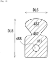
- the ceramic part 480 extends along the length direction DL8 while having a width that fluctuates in the width direction DL6.
- the width direction DL6 is the same as the front-rear direction described for the slide fastener 90.
- the length direction DL8 is the same as the left-right direction described in relation to the slide fastener 90.
- the maximum width of the ceramic part 480 along the width directionDL6 is less than the maximum length of the ceramic part 480 along the length direction DL8.
- the ceramic part 480 is a part that is slightly elongated.
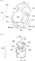
- the ceramic part 480 has a base 481, a neck 482, and a head 483 in this order along the length direction DL8.
- the ceramic part 480 has a constricted shape at the neck 482 between the base 481 and the head 483.
- a relationship is satisfied where the maximum width W481 of the base 481 > the maximum width W483 of the head 483 > the minimum width W482 of the neck 482.
- the width of the ceramic part 480 smoothly changes.
- a shoulder 484 extending toward the head 430 is provided between the base 481 and the head 483.
- the shoulder 484 will be housed by a terminal recess 483k provided at the head 483 of the other one of the engaging pair.
- the base 481 has a receiving portion 485 opening on the opposite side of the head 483.
- the receiving portion 485 has a size that is suitable for receiving the above-described attachment portion 490.
- the receiving portion 485 of the illustrated example has a hollow that is defined by a top plate (first plate) 481a, a bottom plate (second plate) 481b, and side walls 481c, 481d of the base 481.
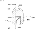
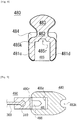
- the receiving portion 485 has a bottom surface 485k at the opposite side of its opening, and the bottom surface 485k is provided with a recess 485r.
- the recess 485r extends in a height direction that is orthogonal to the width and length directions of the ceramic part 480. In another example, the recess 485r extends in another direction.
- the attachment portion 490 has a protrusion 490r that is fitted with the recess 485r of the ceramic part 480. Fitting of the protrusion and the recess would reinforce the coupling of the ceramic part 480 and the attachment portion 490.
- the base 481 has an insertion mouth at the opposite side of the head 483, and has a tape-insertion groove (this may simply be referred to as a groove) 486 that penetrates the base 481 in the width direction.
- the receiving portion 485 opening on the opposite side of the head 483 is provided in the base 481, and thus the tape-insertion groove 486 is spatially coupled with the hollow of the receiving portion 485 and is divided into a first groove 486m and a second groove 486n by the hollow of the receiving portion 485.
- the side wall 481c of the base 481 is provided with the first groove 486m.
- the side wall 481d of the base 481 is provided with the second groove 486n.
- the first groove 486m and the second groove 486n extend linearly in substantially parallel to the length direction of the ceramic part 480. As would be understood from Fig. 7 , in the illustrated example, the first groove 486m and the second groove 486n are provided in the middle position between the top plate 481a and the bottom plate 481b, and have a narrowing terminal shape toward the head 483.
- the tape side-edge portion 310 (the core provided there in some cases) is inserted in to the tape-insertion groove 486 of the base 481 of the ceramic part 480.
- the protrusion 490r of the attachment portion 490 is fitted with the recess 485r provided at the bottom surface 485k of the ceramic part 480.
- the attachment portion 490 is moved while the ceramic part 480 is stationary so that the attachment portion 490 is inserted into the receiving portion 485 of the ceramic part 480.
- the ceramic part 480 is moved while the attachment portion 490 is stationary so that the attachment portion 490 is inserted into the receiving portion 485 of the ceramic part 480.
- the attachment portion 490 and the ceramic part 480 are moved to be closer one another.
- the receiving portion 485 of the ceramic part 480 is filled with an ultraviolet curing adhesive (UV curing adhesive) in advance. After the receiving portion 485 and the attachment portion 490 are coupled, ultraviolet rays are irradiated, and the ceramic part 480 and the attachment portion 490 are coupled firmly. It would be possible to use an energy-ray, other than ultraviolet rays, curing resin.
- UV curing adhesive ultraviolet curing adhesive
- the UV curing adhesive is not used.
- the attachment portion 490 is pressed into the receiving portion 485 so that firm coupling of the ceramic part 480 and the attachment portion 490 is secured.
- fitting between the recess 485r of the ceramic part 480 and the protrusion 490r of the attachment portion 490 would suppress rattling movement of the attachment portion 490 in the receiving portion 485.
- a fastener stringer 80 is configured by directly attaching a ceramic part 480 to a fastener tape 300 by using a fixing member.
- the ceramic part 480 is directly attached to the fastener tape 300 by the fixing member, instead of being attached thereto via the above-described attachment portion 490.
- the ceramic part 480 configures an entirety of one fastener element 400.
- the fastener element 400 is a ceramic element that is made of ceramic material. Methods of securing the ceramic part 480 to the tape side-edge portion 310 would be sewing, for example.
- adhesive is used or a combination of bolt and nut is used. Thread, adhesive, and bolt/nut are generally referred to as a fixing member.
- the ceramic part 480 illustrated in Fig. 10 has an insertion mouth at the opposite side of the head 483, and has a tape-insertion groove 486 that penetrates the base 410 in the width direction.
- the ceramic part 480 has a top plate 481a and a bottom plate 481b that is separated by the tape-insertion groove 486.
- the base 481 of the ceramic part 480 is provided with a hole 488 as an alternative to (or in addition to, in some embodiments) the receiving portion 485 of the ceramic part 480 in Fig. 5 .
- the hole 488 penetrates the top plate 481a and penetrates the bottom plate 481b.
- the hole 488 includes a top hole 488m in the top plate 481a and a bottom hole 488n in the bottom plate 481b.
- the top plate 481a has an opposing inner surface that faces the bottom plate 481b, and a top surface that is opposite to the opposing inner surface.
- the bottom plate 481b has an opposing inner surface that faces the top plate 481a, and a bottom surface that is opposite to the opposing inner surface.
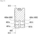
- the top surface of the top plate 481a is provided with a guide groove 481k that has a substantially semi-circular shape in a cross section and extends in the width direction of the ceramic part 480.
- the bottom surface of the bottom plate 481b is provided with a guide groove 481t that has a substantially semi-circular shape in a cross section and extends in the width direction of the ceramic part 480.
- the hole 488 is provided at the center of the guide groove 481k, 481t in the width direction, and the guide groove 481k, 481t is divided into first and second sections by the hole 488.
- the shape of the hole 488 in the elevational view is a circle.
- the shape of the hole 488 in elevational view could be triangle or rectangle or other polygons or start.
- the ceramic part 480 can be directly attached to the fastener tape 300 by the fixing member.
- the ceramic part 480 can be attached to the tape side-edge portion 310 by sewing using threads 510.
- the thread 510 is an example of a fixing member.
- a step is performed in which the tape side-edge portion 310 is inserted into the tape-insertion groove 486 of the ceramic part 480. It would be possible to move the fastener tape 300 while the ceramic part 480 is stationary so that the tape side-edge portion 310 is inserted into the tape-insertion groove 486 of the ceramic part 480. It would be possible to move the ceramic part 480 while the fastener tape 300 is stationary so that the tape side-edge portion 310 is inserted into the tape-insertion groove 486 of the ceramic part 480. Both of the fastener tape 300 and the ceramic part 480Can be moved so as to be closer one another.
- one top thread 511 and two bottom threads 512 are used to sew the ceramic part 480 to the tape side-edge portion 310.
- the top thread 511 extends so as to sew the top plate 481a of the ceramic part 480 onto the tape top surface 301 of the fastener tape 300.
- the bottom thread 512 extends so as to sew the bottom plate 481b of the ceramic part 480 onto the tape bottom surface 302 of the fastener tape 300.
- the top thread 511 extends on the top plate 481a of the ceramic part 480, in particular is arranged in the guide groove 481k and is positioned on the top plate 481a.
- the top thread 511 has portions, appearing at the side of the tape bottom surface 302 or extending on the tape bottom surface 302, in the hole 488 and at both neighboring positions of the ceramic part 480 in the width direction of the ceramic part 480. Accordingly, stable attachment of the ceramic part 480 to the fastener tape 300 would be facilitated.
- the bottom thread 512 extends on the bottom plate 481b of the ceramic part 480, in particular is arranged in the guide groove 481t and is positioned on the bottom plate 481b.
- the bottom thread 512 has portions, appearing at a side of the tape top surface 301 or extending on the tape top surface 301, in the hole 488 and at both neighboring positions in the width direction of the ceramic part 480. Accordingly, stable attachment of the ceramic part 480 to the fastener tape 300 would be facilitated.
- plural ceramic parts 480 are fixed to a web 520 by adhesive, and this is sewn to the tape side-edge portion 310. Spacing between the ceramic parts 480 in the web 520 is properly set so that unintentional displacement of ceramic part 480 during a step of sewing would be avoided or suppressed.
- the web 520 is an elongated member that is elongated in the same direction as the fastener tape 300.
- the web 520 may be a flexible member, e.g. cloth, resin-made sheet, or rubber-made sheet, which has a carrier surface 521 on which the ceramic parts 480 are placed and an opposite surface 522 that is opposite to the carrier surface 521.
- the web 520 is an elastomer-made sheet.
- the web 520 has a thermal conductivity that is less than that of the ceramic part 480. The web 520 contributes in suppressing a sense of cool that could be given to a human when the ceramic part 480 comes into a direct contact with a human skin.
- the order of producing of a fastener stringer 80 would be as follows. Firstly, the plural ceramic parts 480 are fixed to the web 520 by adhesive and so on. Various types of adhesives can be used. An embodiment is envisioned where recesses for positioning the ceramic parts 480 are provided on the web 520. Next, the tape side-edge portion 310 is inserted into the tape-insertion groove 486 of the ceramic part 480. Accordingly, the bottom plate 481b of the base 481 of the ceramic part 480 is sandwiched between the tape side-edge portion 310 and the web 520. Next, the web 520, the ceramic part 480 and the fastener tape 300 are sewn together by the use of threads 510.
- top thread 511 and one bottom thread 512 are used so that the ceramic part 480 is sewn to the tape side-edge portion 310.
- the top thread 511 extends straight in the guide groove 481k of the top plate 481a of each ceramic part 480 and is engaged with the bottom thread 512 in the hole 488 of each ceramic part 480.
- the bottom thread 512 extends along the length direction of the web 520 in the opposite surface 522 of the web 520, and is engaged with the top thread 511 in the hole 488 of each ceramic part 480.
- the top thread 511 forms a loop in the hole 488 of each ceramic part 480 and the bottom thread 512 passes through this loop of the top thread 511.
- the ceramic part 480 constitutes a fragment of a fastener element 400.
- the ceramic part 480 is secured to a resin-made or metal-made attachment portion 490 that has been fixed to the tape side-edge portion 310 in advance.
- a pair of ceramic parts 480 are secured while sandwiching the tape side-edge portion 310.
- the ceramic part 480 constitutes one (fragment) of halves of one fastener element 400.
- the attachment portion 490 fixed to the tape side-edge portion 310 constitutes the other one (fragment) of the halves.
- the fastener element is divided into two halves by a plane being parallel to the tape top surface 301 of the fastener tape 300 and being positioned slightly above the tape top surface 301.
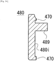
- the ceramic part 480 has a faying surface 480i that is in accordance with the above-described division of one fastener element 400 into two halves.
- the faying surface 480i that exists in the head 483 of the ceramic part 480 is provided with one mating protrusion 489.
- the attachment portion 490 has a faying surface 490i that may come into surface-contact with the faying surface 480i of the ceramic part 480.
- the faying surface 490i that exists in the head 493 of the attachment portion 490 is provided with one mating recess 499.
- the attachment portion 490 has a base 491, a neck 492, and a head 493 in this order, similar to the fastener element 400 and the ceramic part 480.
- the base 491 of the attachment portion 490 is a part of the base of the fastener element 400.
- the neck 492 of the attachment portion 490 is a part of the neck of the fastener element 400.
- the head 493 of the attachment portion 490 is a part of the head of the fastener element 400.
- the mating protrusion 489 of the ceramic part 480 is fitted with the mating recess 499 of the attachment portion 490 so that coupling of the ceramic part 480 and the attachment portion 490 is achieved.
- the ceramic part 480 is provided with the mating recess 499, and the attachment portion 490 is provided with the mating protrusion 489.
- the mating protrusion and the mating recess may be generally referred to as an engaging structure.
- press-fit, adhesion, or combination thereof is performed, and thus firm coupling of the ceramic part 480 and the attachment portion 490 would be secured.
- the rim of the faying surface 490i of the attachment portion 490 is provided with a peripheral wall 470 so that a reservoir for adhesive is formed on the faying surface 490i of the attachment portion 490.
- a peripheral wall 470 is provided on the faying surface 480i of the ceramic part 480 so that a reservoir for adhesive is formed on the faying surface 480i of the ceramic part 480.
- Use of adhesive would ensure more secure bonding between the fragments, not necessarily limited to through.
- a pair of ceramic parts 480 are secured while sandwiching the tape side-edge portion 310.
- the ceramic part 480 placed onto the tape top surface 301 of the fastener tape 300 would be referred to as a top ceramic part 480M
- the ceramic part 480 placed onto the tape bottom surface 302 would be referred to as a bottom ceramic part 480N.
- the top ceramic part 480M and the bottom ceramic part 480N are ceramic parts 480 that have the same configuration. In another embodiment, the top ceramic part 480M and the bottom ceramic part 480N have different configurations.
- the ceramic part 480 has a faying surface 480i that is in accordance with the above-described division of one fastener element 400 into two halves.
- the faying surface 480i is provided across the head 483, the neck 482, and a part of the base 481 of the ceramic part 480.
- the ceramic part 480, i.e. the illustrated head 483 has a faying surface 480i that is shaped asymmetry with respect to an imaginary plane being positioned at the center in the width direction DL6 of the ceramic part 480 and being orthogonal to the direction along the tape side-edge portion 310 of the fastener tape 300.
- the base 481 of the ceramic part 480 is provided with a half-groove 486h that constitutes a half of the tape-insertion groove 486.
- the half-groove 486h is a groove that is a part of the tape-insertion groove 486.
- the base 481 of the ceramic part 480 is provided with a flat surface 487 that touches the tape side-edge portion 310.
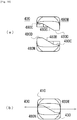
- the faying surface 480i has a first surface 480A that is provided in the base 481, a second surface 480B that is provided across the head 483 and the neck 482 and closer to a terminal end than the first surface 480A, and third and fourth surfaces 480C, 480D that are provided to sandwich the second surface 480B.
- the first surface 480A and the second surface 480B of one ceramic part 480 touches the first surface 480A and the second surface 480B of the other ceramic part 480.
- the third surface 480C of one ceramic part 480 touches the fourth surface 480D of the other ceramic part 480.
- the fourth surface 480D of one ceramic part 480 touches the third surface 480C of the other ceramic part 480.
- the faying surface 480i provided at the head 483 has the second surface 480B that is oriented at a given angle, i.e. obliquely relative to the flat surface 487 and the first surface 480A provided in the base 481.
- the obliquely arranged second surface 480B would allow increased surface-contact area of the top ceramic part 480M and the bottom ceramic part 480N.
- the top ceramic part 480M and the bottom ceramic part 480N are arranged to sandwich the tape side-edge portion 310 and they are coupled together.
- movement of each ceramic part 480 as schematically illustrated by an arrow in Fig. 28 (b) is suppressed owing to the oblique second surface 480B.
- the top and bottom ceramic parts 480M, 480N are firmly secured to the tape side-edge portion 310 and to the other ceramic part 480 of the pair by adhesive.
- the top and bottom ceramic parts 480M, 480N can be coupled together, using a bolt 531 and a nut 532, while the tape side-edge portion 310 is sandwiched.
- a hole is provided at each ceramic part 480 to allow an axial portion of the bolt 531 to be inserted therein.
- Each ceramic part 480 may be provided with a step portion for housing a head of the bolt 531 or the nut.
- the fastener element 400 is divided into three fragments or more, unlike examples illustrated in Figs. 19 to 29 .
- An embodiment is envisioned where the fastener element is divided into two halves or three fragments or more by a plane orthogonal to the tape top surface 301 of the fastener tape 300, unlike examples illustrated in Figs. 19 to 29 .
- the ceramic part 480 is provided with the tape-insertion groove 486.
- the fragment is provided with a receiving portion 485 for receiving the attachment portion 490 (or a part of the receiving portion 485).
- the fragment is provided with a hole through which a thread is passed.
- the ceramic part 480 constitutes an entirety of one fastener element 400.
- the fastener element 400 is a ceramic element made of ceramic material. Adhesive would be an example as means for attaching the ceramic part 480 to the tape side-edge portion 310. However, in another embodiment, adhesive is utilized, and the ceramic part 480 is attached to the fastener tape 300.
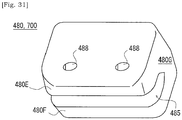
- the ceramic part 480 constitutes an entirety of one stop member 700.
- the stop member 700 is a ceramic stop member made of ceramic material.
- the ceramic part 480 has a top leg 480E that is placed onto the tape top surface 301 of the fastener tape 300, a bottom leg 480F that is placed onto the tape bottom surface 302, and a coupling portion 480G that couples the top leg 480E and the bottom leg 480F.
- the top leg 480E is provided with holes 488 through or into which a thread or an axial portion of a bolt is passed or inserted.
- the ceramic part 480 constitutes an entirety of, a shell of, or a fragment of the stop member 700.
- Fig. 32 discloses a slide fastener 90 configured differently from Fig. 1 . There is no reason that specific shape of the fastener element 400 or the stop member 700 is limited to that of Fig. 1 .
- the ceramic part 480 constitutes an entirety of, a shell of, or a fragment of the fastener element 400 or the stop member 700 disclosed in Fig. 32 .
- the ceramic part 480 constitutes an entirety of, a shell of, or a fragment of the fastener element 400 or the stop member 700
- a method of attaching it to the fastener tape 300 would be a technical challenge.
- the ceramic part 480 alone includes the tape-insertion groove 486, or the ceramic part 480 includes a structure that configures the tape-insertion groove 486 together with the other ceramic part 480 being combined, i.e. the above-described half-groove 486h. Accordingly, it would be possible to attach the ceramic-made or semi-ceramic-made fastener element 400 or the stop member 700 to a commonly-used fastener tape that do not have high heat resistance.
- the ceramic part 480 includes zirconia.
- Fracture toughness of zirconia is greater than those of alumina or silicon oxide. Therefore, it would be possible to supply the fastener elements or stop members that are mechanically strong.
- zirconia has transparency and is used as a jewelry item. Use of zirconia would allow provision of new appearance of an extraordinary fastener stringer in wide applications including bags, clothes, and fishnets and, at the same time, there is no need to make sacrifices to the characteristics of the fastener element or the stop member.
Landscapes
- Slide Fasteners (AREA)
Abstract
Description
- The present disclosure is related to a ceramic part, a fastener stringer including the same, and a method of producing a fastener stringer.
- Patent literature 1 discloses in its paragraph 0043 that, for a fastener element molded from plastic material, ceramic material can be used in another working example.
- [PTL 1] Japanese Patent No.
5,207,142 - It is desired for component parts of a slide fastener secured to a fastener tape, e.g. fastener elements or stop members, to obtain a novel design while enhancing wear resistance, heat resistance, corrosion resistance, acid resistance, and/or alkali resistance.
- It should be noted that Patent literature 1 does not disclose a ceramic part as would be described in the following paragraphs of the present specification which is a separated part from a fastener tape.
- A ceramic part according to an aspect of the present disclosure may be a ceramic part (480) directly or indirectly attachable to a tape side-edge portion (310) of a fastener tape (300) of a slide fastener (90), wherein the ceramic part (480) constitutes an entirety of a component part (400, 700) of the slide fastener (90) that is to be secured to the tape side-edge portion (310) of the fastener tape
- (300), or a shell of the component part (400, 700), or a fragment of the component part (400, 700).
- The ceramic part may be prepared separately from the fastener tape. The ceramic part may constitute an entirety of, or a shell of, or a fragment of a component part, e.g. a fastener element or a stop member of the slide fastener. The ceramic part can be obtained at least via molding and firing of ceramic material. The composition or ingredients of the ceramic part would be properly determined, and it could present a desired design. The ceramic part may include an inorganic pigment in one case, and the ceramic part may not include an inorganic pigment in another case. The component part of the slide fastener including this ceramic part may obtain a novel design while having enhanced wear resistance, heat resistance, corrosion resistance, acid resistance, and/or alkali resistance.
- In some embodiments, a tape-insertion groove (486) is provided at least partially into which the tape side-edge portion (310) of the fastener tape (300) is to be inserted and/or a partial groove (486h) is provided that is a part of the tape-insertion groove (486).
- Some embodiments may further include a receiving portion (485) that is capable of at least partially receiving an attachment portion (490) provided at a tape side-edge portion (310) of a fastener tape (300).
- In some embodiments, a hole (488) may be provided that is spatially coupled to the tape-insertion groove (486).
- Some embodiments may include at least one engaging structure (489) to be fitted with an attachment portion (490) provided at a tape side-edge portion (310) of a fastener tape (300) and/or to be fitted with other fragment of the component part (400, 700).
- In some embodiments, the component part (400, 700) may be a fastener element (400) or a stop member (700).
- In some embodiments, the component part (400, 700) may be a fastener element (400), and the ceramic part may include:
- a head (483) that is an entirety of or a part of a head of the fastener element (400);
- a base (481) that is an entirety of or a part of a base of the fastener element (400); and
- a neck (482) that is an entirety of or a part of a neck of the fastener element (400).
- In some embodiments, the component part (400, 700) may be a fastener element (400), and the ceramic part may include:
- a head (483) that is a part of a head of the fastener element (400);
- a base (481) that is a part of a base of the fastener element (400); and
- a neck (482) that is a part of a neck of the fastener element (400).
- In some embodiments, the base (481) may be provided with a groove (486) or a partial groove (486h) that may extend so as to penetrate the base (481).
- In some embodiments, the base (481) may be provided with first plate (481a) and second plate (481b) which are separated by a groove (486) that extends so as to penetrate the base (481), and wherein the first plate (481a) and/or the second plate (481b) is provided with one or more holes (488m, 488n).
- In some embodiments, the head (483) and/or the base (481) and/or the neck (482) may be provided with a faying surface (480i) that is shaped asymmetrically relative to a given imaginary plane.
- In some embodiments, the imaginary plane may be orthogonal to a direction extending along the tape side-edge portion (310) of the fastener tape (300).
- A fastener stringer according to another aspect of the present disclosure may be a fastener stringer (250) including:
- a fastener tape (300);
- a plurality of fastener elements (400) fixed to a tape side-edge portion (310) of the fastener tape (300), wherein
- each fastener element (400) included in the plurality of fastener elements (400) may include a ceramic part (480) constituting an entirety of, or a shell of, or a fragment of the fastener element (400).
- In some embodiments, the fastener element (400) may include an attachment portion (490) provided at the tape side-edge portion (310) of the fastener tape (300).
- In some embodiments, the attachment portion (490) may include:
- a head (493) that is an entirety of or a part of a head of the fastener element (400);
- a base (491) that is an entirety of or a part of a base of the fastener element (400); and
- a neck (492) that is an entirety of or a part of a neck of the fastener element (400).
- In some embodiments, the attachment portion (490) may be a resin portion fixed to the tape side-edge portion (310) of the fastener tape (300).
- A method of producing a fastener stringer according to another aspect of the present disclosure may include:
- preparing a ceramic part (480) that constitutes an entirety of a component part (400, 700) of a slide fastener (90) that is to be secured to a tape side-edge portion (310) of a fastener tape (300), or a shell of the component part (400, 700), or a fragment of the component part (400, 700); and
- attaching the ceramic part (480) directly or indirectly to the fastener tape (300) of the slide fastener (90).
- In some embodiments, said attaching the ceramic part (480) directly or indirectly to the fastener tape (300) may include inserting the tape side-edge portion (310) of the fastener tape (300) into a tape-insertion groove (486) of the ceramic part (480).
- In some embodiments, said attaching the ceramic part (480) directly or indirectly to the fastener tape (300) may include coupling the ceramic part (480) to an attachment portion (490) provided at the tape side-edge portion (310) of the fastener tape (300).
- In some embodiments, the ceramic part (480) may constitute the fragment of the component part (400, 700), and said attaching the ceramic part (480) directly or indirectly to the fastener tape (300) may include sandwiching the tape side-edge portion (310) of the fastener tape (300) by a plurality of fragments of the component part (400, 700).
- In some embodiments, said attaching the ceramic part (480) directly or indirectly to the fastener tape (300) may include sewing the ceramic part (480) to the fastener tape (300) with thread.
- According to an aspect of the present disclosure, for component parts of a slide fastener secured to a fastener tape, e.g. fastener elements or stop members, a novel design would be obtained while enhanced wear resistance, heat resistance, corrosion resistance, acid resistance, and/or alkali resistance is achieved.
-
- [
Fig. 1] Fig. 1 is a schematic elevational view of a slide fastener according to an aspect of the present disclosure. - [
Fig. 2] Fig. 2 is a schematic flowchart of a method of producing a fastener stringer according to an aspect of the present disclosure. - [
Fig. 3] Fig. 3 is a schematic flowchart of a method of producing a ceramic part according to an aspect of the present disclosure. - [
Fig. 4] Fig. 4 is a schematic perspective view of a pair of half-finished fastener stringers according to an aspect of the present disclosure. - [
Fig. 5] Fig. 5 is a schematic perspective view of a ceramic part that constitutes a shell of a fastener element included in a fastener stringer ofFig. 4 . - [
Fig. 6] Fig. 6 is a schematic top view of a ceramic part ofFig. 5 . - [
Fig. 7] Fig. 7 is a schematic cross-sectional view of a ceramic part taken along the line VII-VII inFig. 6 . - [
Fig. 8] Fig. 8 is a schematic cross-sectional view of a ceramic part taken along the line VIII-VIII inFig. 7 . - [
Fig. 9] Fig. 9 is a schematic cross-sectional view showing a coupled manner of a ceramic part and an attachment base. - [
Fig. 10] Fig. 10 is a schematic perspective view of a ceramic part according to another embodiment of the present disclosure. This ceramic part constitutes an entirety of a fastener element. Hereinafter, in a case in which a ceramic part is identical to a fastener element, a fastener element may be simply referred to as a "ceramic element". - [
Fig. 11] Fig. 11 is a schematic cross-sectional view of a ceramic part taken along the line XI-XI inFig. 10 . - [
Fig. 12] Fig. 12 is a schematic cross-sectional view of a ceramic part taken along the line XII-XII inFig. 11 . - [
Fig. 13] Fig. 13 is a schematic elevational view of a fastener stringer, including fastener elements ofFig. 10 , according to another embodiment of the present disclosure - [
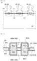
Fig. 14] Fig. 14 is a schematic cross-sectional view of a fastener stringer taken along the line XIV-XIV inFig. 13 . - [
Fig. 15] Fig. 15 is a schematic perspective view of a half-finished fastener stringer according to another embodiment of the present disclosure, illustrating a state before ceramic elements fixed onto a web by adhesive are attached to a fastener tape by sewing. - [
Fig. 16] Fig. 16 is a schematic elevational view of a fastener stringer, illustrating a state in which ceramic elements, fixed onto a web by adhesive, are attached to a fastener tape by sewing. - [
Fig. 17] Fig. 17 is a schematic elevational view of a fastener stringer, illustrating the opposite side ofFig. 16 . - [
Fig. 18] Fig. 18 is a schematic cross-sectional view of a fastener stringer taken along the line XVIII-XVIII inFig. 16 . - [
Fig. 19] Fig. 19 is a schematic perspective view of a half-finished fastener stringer according to another embodiment of the present disclosure. - [
Fig. 20] Fig. 20 is schematic elevational and cross-sectional views of a ceramic part that configures one fragment of a fastener element included in a fastener stringer ofFig. 19. Fig. 20 (b) illustrates a schematic cross-sectional configuration taken along the line XXb-XXb inFig. 20 (a) . - [
Fig. 21] Fig. 21 is schematic elevational and cross-sectional views of an attachment base that constitutes the other fragment of a fastener element included in a fastener stringer ofFig. 19 .Fig. 21 (b) illustrates a schematic cross-sectional configuration taken along the line XXIb-XXIb inFig. 21 (a) . - [
Fig. 22] Fig. 22 is a schematic cross-sectional view of a semi-ceramic element that is configured by a ceramic part being coupled to an attachment base which are shown inFigs. 20 and21 . It should be noted that the semi-ceramic element indicates a fastener element that consists of a ceramic part and non-ceramic part. - [
Fig. 23] Fig. 23 is a schematic perspective view illustrating an attachment base of another example which constitutes a fragment. - [
Fig. 24] Fig. 24 is a schematic perspective view illustrating a ceramic part of another example which constitutes a fragment. - [
Fig. 25] Fig. 25 is a schematic perspective view of a half-finished fastener stringer according to another embodiment of the present disclosure. - [
Fig. 26] Fig. 26 is a schematic perspective view of a ceramic part that constitutes a fragment of a fastener element included in a fastener stringer ofFig. 25 . - [
Fig. 27] Fig. 27 is a schematic process view of manufacturing of a fastener stringer ofFig. 25 , illustrating how a fastener stringer and a ceramic element are assembled in a cross-section taken along a cross-sectional plane XXVII-XXVII inFig. 25 . - [
Fig. 28] Fig. 28 is a schematic process view of manufacturing of a fastener stringer ofFig. 25 , illustrating that a head of one fragment and a head of the other fragment are assembled so that a head of a ceramic element is configured. - [
Fig. 29] Fig. 29 is a schematic cross-sectional view illustrating a state in which a ceramic element is secured to a fastener tape by a fixing member of a bolt and a nut. - [
Fig. 30] Fig. 30 is a schematic perspective view illustrating a ceramic element of another example. - [
Fig. 31] Fig. 31 is a schematic perspective view illustrating a ceramic stop member of another example. - [
Fig. 32] Fig. 32 is a schematic elevational view illustrating a slide fastener of another example. - Hereinafter, non-limiting exemplary embodiments of the present invention will be described with references to
Figs. 1 to 32 . One or more disclosed embodiments and respective features included in the embodiment are not mutually exclusive. A skilled person would properly combine the respective embodiments and/or respective features without requiring excess descriptions. A skilled person would also understand synergic effect by such combinations. Overlapping descriptions among embodiments will be basically omitted. Referenced drawings are mainly for the purpose of illustrating an invention and may possibly be simplified for the sake of convenience of illustration. - As shown in
Fig. 1 , aslide fastener 90 has a pair of left-right fastener stringers 80, and aslider 40 for opening and closing the paired left-right fastener stringers 80. Eachfastener stringer 80 has afastener tape 300, andfastener elements 400 and stopmembers 700 which are attached to a tape side-edge portion 310 of thefastener tape 300. Thefastener tape 300 may be a woven or knitted fabric, but could take other forms. Thefastener tape 300 has a tapetop surface 301 and a tape bottom surface that is opposite to the tapetop surface 301. The thickness of thefastener tape 300 is defined by the tapetop surface 301 and the tape bottom surface. In some cases, the tape side-edge portion 310 is provided with a core. An embodiment is envisaged in which the tape side-edge portion 310 is not provided with a core. - The
fastener element 400 has a base 410 fixed to the tape side-edge portion 310, ahead 430 that is provided outwardly of fastener tape relative to thebase 410, and aneck 420 of a narrowed width interposed between the base 410 and thehead 430. Thefastener element 400 has a constricted shape at theneck 420 between the base 410 and thehead 430. It should be noted that, "outwardly of fastener tape" is identical to a direction directed from a point or position over the tape top surface or the bottom surface of the fastener tape to a point or position external of the tape top surface or the bottom surface of the fastener tape. Typically, outwardly of fastener tape is indicated by an arrow AL9 inFig. 1 . The arrow AL9 is in parallel to the tape top surface or the bottom surface of thefastener tape 300, and extends so as to be orthogonal to the tape side-edge portion 310. Inwardly of fastener tape is a direction directed to the opposite side of said outwardly of fastener tape. - The
slider 40 may be made of metal or resin or ceramic. Frontward movement of theslider 40 closes the left-right fastener stringers 80, and its rearward movement opens the left-right fastener stringers 80. For aslide fastener 90, front-rear direction would be understood in accordance with moving direction of aslider 40. For aslide fastener 90, left-right direction is a direction that is orthogonal to the front-rear direction and is in parallel to the tape top surface or the bottom surface of thefastener tape 300. For aslide fastener 90, up-down direction is a direction that is orthogonal to the front-rear direction and the left-right direction. - The
slider 40 has a top wing, a bottom wing opposed to the top wing, and a coupling pillar that couples the top wing and the bottom wing. The top wing is provided with a pull tab attachment pillar, and a pull tab is attached thereto. The top wing of theslider 40 has a first opposing inner surface that faces the bottom wing. The bottom wing of theslider 40 has a second opposing inner surface that faces the top wing. When theslide fastener 90 is used, thefastener element 400 may touch or hit the first opposing inner surface of the top wing, the second opposing inner surface of the bottom wing, and/or the coupling pillar. Therefore, it is requested to secure sufficient attachment strength of thefastener elements 400 to thefastener tape 300. Also, thefastener elements 400 are requested to have sufficient durability to withstand a wear due to contact with theslider 40. Likewise, thestop member 700 would be required to have the sufficient attachment strength and the sufficient wear resistance. - In the
slide fastener 90, the left-right fastener stringers 80 may possibly be pulled laterally in opposite directions in the left-right direction. Theslide fastener 90 would be required to have sufficient durability to withstand this lateral pulling. Note that, when damage of a fastener tape or damage of a fastener element is caused in a test of pulling a slide fastener laterally, the slide fastener would be determined as defective. - The
fastener element 400 and thestop member 700 are component parts of theslide fastener 90 that are secured to thefastener tape 300 of theslide fastener 90. In the present embodiment, the component part of thisslide fastener 90 includes a ceramic part. The ceramic part constitutes an entirety of, or a shell of, or a fragment of the component part of theslide fastener 90. The ceramic part mainly consists of ceramic material. - The component part of the
slide fastener 90 may be assembled and configured from one or more parts, not necessarily limited to through. In some cases, the component part of theslide fastener 90 includes an attachment base and a shell. The attachment base may be a portion fixed to the tape side-edge portion 310. The shell may be a portion that covers the attachment base. The attachment base could possibly be understood as a core part. - In some cases, the component part of the
slide fastener 90 is configured from one or more fragments. In some cases, the component part of theslide fastener 90 is configured from two fragments. In cases where the component part of theslide fastener 90 is divided into two halves, one fragment may be a ceramic part and the other fragment may be an attachment base that is fixed to the tape side-edge portion 310. In some cases where the component part of theslide fastener 90 is divided into two halves, both fragments may be ceramic parts. - In some cases, the ceramic part constitutes an entirety of, or a shell of, or a fragment of the
fastener element 400. In some cases, the ceramic part constitutes an entirety of, or a shell of, or a fragment of thestop member 700. Thestop member 700 may include both types of astop member 710 that allows decoupling and coupling of the left-right fastener stringers 80 as illustrated inFig. 1 and astop member 720 that does not allow decoupling and coupling of the left-right fastener stringers 80. Thestop member 720 may be referred to as a separable stop. Thestop member 720 includes a box to which a box bar is coupled, and an insertion bar to be held by the box by being inserted into a hollow in the box so as to be adjacent to the box bar. - Ceramic material has been so far never considered as material of component parts of a
slide fastener 90 that are secured to thefastener tape 300 of theslide fastener 90. This is because, in a fastening industry, it has been a common technical understanding thatfastener elements 400 or stopmembers 700 are made of metal or resin. For example, a metal-made element can be produced by cutting a metal wire rod of a base member, and it can be attached to a side-edge portion of a fastener tape via a step of swaging. Regarding the resin-made element, molding thereof and fixing thereof to a fastener tape could be simultaneously performed by injection-molding in which a side-edge portion of a fastener tape is arranged in a mold. In contrast, it would be immediately recognized that the benefits of the easiness of deformation of metal-made element and the easiness of molding and fixing of resin-made element would be lost with respect to fastener elements made of ceramic. - The ceramic part may be produced via a step of molding a mixture of ceramic powder and binder etc., and a following step of firing. Ceramic molded articles produced by molding are generally mechanically fragile because a binder is contained. The step of firing at extremely high temperature higher than at least 1000°C may possibly be necessary as the step of molding that should follow the step of molding. This temperature would be adequate for a general fastener tape to burn.
- The present inventors have truly studied, contrary to the above-described common technical understanding, on the use of ceramic material as material of component parts of a
slide fastener 90 that are secured to afastener tape 300 ofslide fastener 90. The present inventors have newly discovered the meaningfulness of preparing a ceramic part separately from a fastener tape, and directly or indirectly attaching this to a fastener tape. Accordingly, it would be possible to provide component parts of a slide fastener with new design and with enhanced wear resistance, heat resistance, corrosion resistance, acid resistance, and/or alkali resistance. The ceramic part constitutes an entirety of, or a shell of, or a fragment of a component part of theslide fastener 90, and thus a certain degree of attaching efficiency to a fastener tape would be secured. - Note that, as described above, the ceramic part may be produced via the step of molding of a mixture of ceramic powder, binder and etc., and the following step of firing. The ceramic part may mainly consist of ceramic material. The ceramic part can be referred to as a ceramic fired body.
- There may be a case where compromises of reduced functionalities of wear resistance, heat resistance, corrosion resistance, acid resistance, or alkali resistance and the like are required to obtain new design of the above-described component part. As an outstanding point, the ceramic part included in the component part of the slide fastener provides its enhanced functionality rather than a drastic drop of its functionality when obtaining its new design.
- A method of producing a ceramic part may be accompanied by the steps of molding and firing. In some cases, pellets made by drying and granulating a mixture of ceramic powder and binder (bonding agent) may be used when molding, not necessarily limited to through. In order to adjust the color of ceramic parts, inorganic pigment may possibly be mixed into the ceramic powder and binder. The binder may typically be an organic binder which can be removed by heating. The binder can include plural types of organic substances. For example, the binder can include polyvinyl alcohol, methyl cellulose, acrylic resin, and agar etc. Molding of ceramic powder can be done by using injection-molding, but of course other methods of molding can be used. Molding of ceramic powder would produce a ceramic molded article. Firing of the ceramic molded article would produce a ceramic fired article in which organic binder and other volatile components have been removed. Appropriately set condition of firing, e.g. temperature profile may ensure a desired transparency of a ceramic fired article. If the main purpose of firing is to remove the organic binder, then the firing could be referred to as degreasing.
- Considerations will be made for cases where the ceramic part constitutes an entirety of the
fastener element 400 or thestop member 700. In this case, extremely high durability against contact or hit with theslider 40 would be obtained. The risk of partially damaging thefastener element 400 or thestop member 700 in the test of pulling laterally would be nearly zero. Also, more sufficient corrosion resistance, acid resistance or alkali resistance would be obtained than resin-made element or metal-made element. There are cases where theslide fastener 90 is incorporated into a wet suit or where it is used for coupling fishnets. It is also envisioned that theslide fastener 90 is used in much severe environments than the cases indicated herein such as in a space. Relatively enhanced corrosion resistance, acid resistance or alkali resistance of thefastener element 400 would provide ample benefits. - A case is considered where the ceramic part constitutes a shell of or a fragment of the
fastener element 400 or thestop member 700. The shell and the fragment of thefastener element 400 or thestop member 700 may be portions exposed to the external environment. As the shell and the fragment are configured by the ceramic part, the same benefit as described above would be obtained. In some cases, the use of this ceramic part may contribute in reducing weight of afastener element 400, depending on ingredients of ceramic part. - The composition or ingredients of ceramic part would be properly determined by a skilled person in the art. In some cases, the ceramic part includes at least zirconia. In some cases, the ceramic part mainly consists of zirconia. Zirconia may be referred to as zirconium dioxide (ZrO2). Zirconia can include additive(s). Zirconia in which rare-earth oxide as an additive is solid-solved may be referred to as stabilized zirconia or partially stabilized zirconia. As the rare-earth oxide, calcium oxide, magnesium oxide, and yttrium oxide can be exemplified. Zirconia has a very high melting point, and can have a desired transparency if condition of firing is appropriately set. In a case where the
fastener element 400 or thestop member 700 includes zirconia, an appearance that is different from a clear-coating can be given. Additionally to mechanical or chemical property such as the above-described wear resistance, heat resistance, corrosion resistance, acid resistance, or alkali resistance, thefastener element 400 or thestop member 700 can obtain an enhanced appearance. The ceramic part can include one or more types of inorganic pigments additionally to zirconia. The inorganic pigment is dispersed in the ceramic part so that a desired color is given to the ceramic part. For example, the ceramic part can exhibit red, yellow, blue, green, black or white color. - Note that transparency can be imparted to the
fastener element 400 by forming a clear coating onto the resin-made element or the metal-made element. The same applies to thestop member 700. However, this clear coating requires a step of coating, and has a poor mechanical or chemical properties in general. This clear coating is not superior to a ceramic part having a transparency, from a standpoint of design. - In some embodiments, the ceramic part includes cubic zirconia. The existence of cubic zirconia can be proved through inspection using an energy dispersive X-ray analyzer (EDX). In some embodiments, the ceramic part includes alumina, silicon carbide, or aluminum nitride, in addition to zirconia or as an alternative to zirconia. Alumina, silicon carbide, or aluminum nitride may be preferable in a point that they are lighter than zirconia. In some cases, zirconia-containing alumina may be used.
- A method of producing a
fastener stringer 80 would be described with reference toFig. 2 . Firstly, a ceramic part is produced or prepared. Next, a ceramic part is directly or indirectly attached to the fastener tape. As would be understood from the above descriptions, the ceramic part constitutes an entirety of, or a shell of, or a fragment of a component part (e.g. fastener element 400 or stop member 700) of aslide fastener 90 secured to afastener tape 300 of aslide fastener 90. More specific working examples in accordance with the flowchart shown inFig. 2 would be understood from the following descriptions. - A method of producing a ceramic part will be described with reference to
Fig. 3 . Firstly, raw material including ceramic powder is produced. In some cases, this step can include a step of mixing and a step of granulating in this order. An organic binder, ceramic powder, and other necessary ingredients e.g. an inorganic pigment are mixed in the step of mixing. The mixture is then molded into pellets of injection-molded material in the step of granulating. In the step of granulating, a molding roll can be used which receives a mixture extruded from an extruding nozzle and molds the received mixture into pellets. The step of granulating can be accompanied by a step of drying. Next, these pellets are used for molding, e.g. injection-molding under a desired condition. Mold temperature, injecting pressure, and injecting time period would be determined as desired. In a case of injection-molding, more complicated shapes of molded articles would be easily obtained. Next, this ceramic molded article produced as such is fired. The step of firing would be performed under a condition in which organic binder in the ceramic molded article can be evaporated and the ceramic powder can be properly fired. Next, if necessary, the ceramic part obtained by the step of firing is polished. In some cases, a step of preheating is performed between the step of molding and the step of firing so that the organic binder in the molded article can be removed in advance of the full firing. In some cases, the step of preheating is not performed, and the organic binder can be removed during the firing. - Hereinafter, discussions will follow with reference to
Figs. 4 to 31 on configurations of the ceramic part that is a part separated from a fastener tape, methods of direct or indirect attachment thereof to a fastener tape, and/or configurations of a fastener element or a stop member including a ceramic part. - The
fastener stringer 80 illustrated inFig. 4 is produced by attaching aceramic part 480 indirectly to afastener tape 300. In particular, theceramic part 480 is coupled to and installed to a resin-made or metal-madeattachment portion 490 fixed to the tape side-edge portion 310. Theceramic part 480 is indirectly attached to thefastener tape 300, i.e. via theattachment portion 490. In some cases including the illustrated cases, theattachment portion 490 is a resin portion fixed to the tape side-edge portion 310 of thefastener tape 300. - The
ceramic part 480 constitutes a shell of afastener element 400. Thefastener element 400 is comprised of theceramic part 480 forming the shell thereof and theattachment portion 490 encapsulated by the shell. Thefastener element 400 is a semi-ceramic element that is partially made of ceramic material. It should be noted that the shell should not be limited to one that is exposed in the entire external surface of thefastener element 400. In some cases, the shell occupies only a part of the external surface of thefastener element 400. As illustrated inFig. 4 , theattachment portion 490 also constitutes an exposed portion of thefastener element 400. It is not necessary that the ratio between ceramic material and resin material in thefastener element 400 is 50/50 in weight ratio. It is not necessary that the ratio between ceramic material and metal material in thefastener element 400 is 50/50 in weight ratio. - It is possible to produce the
ceramic part 480 through molding and firing as described with reference toFig. 3 . The half-finished fastener stringer 80 excluding theceramic parts 480 includes afastener tape 300 and anattachment portion 490 fixed to the tape side-edge portion 310. In a case where theattachment portion 490 is made of resin, the half-finished fastener stringer 80 can be produced by performing an injection-molding while the tape side-edge portion 310 is arranged in a molding cavity of a mold. In a case where theattachment portion 490 is made of metal, the half-finished fastener stringer 80 can be produced by attaching theattachment portion 490 to the tape side-edge portion 310 through a step of swaging. - In the case of
Fig. 4 , thefastener stringer 80 can be easily produced by inserting and fitting theattachment portion 490, which has been already fixed to the tape side-edge portion 310, into and with theceramic part 480 that constitutes the shell of thefastener element 400. It should be noted that any types of adhesives can be used, depending on a requirement. In some cases, allfastener elements 400 of thefastener stringer 80 are semi-ceramic elements. In other case, only a predetermined pieces offastener elements 400 are semi-ceramic elements. In particular, an embodiment is envisioned where fastener elements which may likely receive an impact are selectively configured as semi-ceramic elements. - As illustrated in
Fig. 5 , theceramic part 480 extends along the length direction DL8 while having a width that fluctuates in the width direction DL6. The width direction DL6 is the same as the front-rear direction described for theslide fastener 90. The length direction DL8 is the same as the left-right direction described in relation to theslide fastener 90. The maximum width of theceramic part 480 along the width directionDL6 is less than the maximum length of theceramic part 480 along the length direction DL8. Theceramic part 480 is a part that is slightly elongated. - Similar to the
fastener element 400, theceramic part 480 has abase 481, aneck 482, and ahead 483 in this order along the length direction DL8. Theceramic part 480 has a constricted shape at theneck 482 between the base 481 and thehead 483. As illustrated inFig. 6 , a relationship is satisfied where the maximum width W481 of the base 481 > the maximum width W483 of thehead 483 > the minimum width W482 of theneck 482. As illustrated inFig. 6 , the width of theceramic part 480 smoothly changes. Ashoulder 484 extending toward thehead 430 is provided between the base 481 and thehead 483. Theshoulder 484 will be housed by aterminal recess 483k provided at thehead 483 of the other one of the engaging pair. - The
base 481 has a receivingportion 485 opening on the opposite side of thehead 483. The receivingportion 485 has a size that is suitable for receiving the above-describedattachment portion 490. The receivingportion 485 of the illustrated example has a hollow that is defined by a top plate (first plate) 481a, a bottom plate (second plate) 481b, andside walls base 481. - The receiving
portion 485 has abottom surface 485k at the opposite side of its opening, and thebottom surface 485k is provided with arecess 485r. Therecess 485r extends in a height direction that is orthogonal to the width and length directions of theceramic part 480. In another example, therecess 485r extends in another direction. It should be noted that theattachment portion 490 has aprotrusion 490r that is fitted with therecess 485r of theceramic part 480. Fitting of the protrusion and the recess would reinforce the coupling of theceramic part 480 and theattachment portion 490. - The
base 481 has an insertion mouth at the opposite side of thehead 483, and has a tape-insertion groove (this may simply be referred to as a groove) 486 that penetrates the base 481 in the width direction. In the illustrated example, the receivingportion 485 opening on the opposite side of thehead 483 is provided in thebase 481, and thus the tape-insertion groove 486 is spatially coupled with the hollow of the receivingportion 485 and is divided into afirst groove 486m and asecond groove 486n by the hollow of the receivingportion 485. Theside wall 481c of thebase 481 is provided with thefirst groove 486m. Theside wall 481d of thebase 481 is provided with thesecond groove 486n. Thefirst groove 486m and thesecond groove 486n extend linearly in substantially parallel to the length direction of theceramic part 480. As would be understood fromFig. 7 , in the illustrated example, thefirst groove 486m and thesecond groove 486n are provided in the middle position between thetop plate 481a and thebottom plate 481b, and have a narrowing terminal shape toward thehead 483. - As illustrated in
Fig. 9 , when theattachment portion 490 is inserted into the receivingportion 485 of theceramic part 480, the tape side-edge portion 310 (the core provided there in some cases) is inserted in to the tape-insertion groove 486 of thebase 481 of theceramic part 480. When theattachment portion 490 is further inserted in the receivingportion 485 of theceramic part 480, theprotrusion 490r of theattachment portion 490 is fitted with therecess 485r provided at thebottom surface 485k of theceramic part 480. - In some cases, the
attachment portion 490 is moved while theceramic part 480 is stationary so that theattachment portion 490 is inserted into the receivingportion 485 of theceramic part 480. In other case, theceramic part 480 is moved while theattachment portion 490 is stationary so that theattachment portion 490 is inserted into the receivingportion 485 of theceramic part 480. In a still further case, theattachment portion 490 and theceramic part 480 are moved to be closer one another. - In some cases, the receiving
portion 485 of theceramic part 480 is filled with an ultraviolet curing adhesive (UV curing adhesive) in advance. After the receivingportion 485 and theattachment portion 490 are coupled, ultraviolet rays are irradiated, and theceramic part 480 and theattachment portion 490 are coupled firmly. It would be possible to use an energy-ray, other than ultraviolet rays, curing resin. - In another case, the UV curing adhesive is not used. The
attachment portion 490 is pressed into the receivingportion 485 so that firm coupling of theceramic part 480 and theattachment portion 490 is secured. - In some cases, fitting between the
recess 485r of theceramic part 480 and theprotrusion 490r of theattachment portion 490 would suppress rattling movement of theattachment portion 490 in the receivingportion 485. - In an illustrated embodiment of
Figs. 10 to 18 , afastener stringer 80 is configured by directly attaching aceramic part 480 to afastener tape 300 by using a fixing member. Theceramic part 480 is directly attached to thefastener tape 300 by the fixing member, instead of being attached thereto via the above-describedattachment portion 490. Theceramic part 480 configures an entirety of onefastener element 400. Thefastener element 400 is a ceramic element that is made of ceramic material. Methods of securing theceramic part 480 to the tape side-edge portion 310 would be sewing, for example. However, in another embodiment, adhesive is used or a combination of bolt and nut is used. Thread, adhesive, and bolt/nut are generally referred to as a fixing member. - Similar to the
ceramic part 480 inFig. 5 , theceramic part 480 illustrated inFig. 10 has an insertion mouth at the opposite side of thehead 483, and has a tape-insertion groove 486 that penetrates the base 410 in the width direction. Theceramic part 480 has atop plate 481a and abottom plate 481b that is separated by the tape-insertion groove 486. Thebase 481 of theceramic part 480 is provided with ahole 488 as an alternative to (or in addition to, in some embodiments) the receivingportion 485 of theceramic part 480 inFig. 5 . Thehole 488 penetrates thetop plate 481a and penetrates thebottom plate 481b. Thehole 488 includes atop hole 488m in thetop plate 481a and abottom hole 488n in thebottom plate 481b. - The
top plate 481a has an opposing inner surface that faces thebottom plate 481b, and a top surface that is opposite to the opposing inner surface. Thebottom plate 481b has an opposing inner surface that faces thetop plate 481a, and a bottom surface that is opposite to the opposing inner surface. The top surface of thetop plate 481a is provided with aguide groove 481k that has a substantially semi-circular shape in a cross section and extends in the width direction of theceramic part 480. The bottom surface of thebottom plate 481b is provided with aguide groove 481t that has a substantially semi-circular shape in a cross section and extends in the width direction of theceramic part 480. Thehole 488 is provided at the center of theguide groove guide groove hole 488. In the illustrated example, the shape of thehole 488 in the elevational view is a circle. However, in another example, the shape of thehole 488 in elevational view could be triangle or rectangle or other polygons or start. - As illustrated in
Fig. 13 , theceramic part 480 can be directly attached to thefastener tape 300 by the fixing member. Theceramic part 480 can be attached to the tape side-edge portion 310 bysewing using threads 510. Again, thethread 510 is an example of a fixing member. - Before a step of
sewing using threads 510, a step is performed in which the tape side-edge portion 310 is inserted into the tape-insertion groove 486 of theceramic part 480. It would be possible to move thefastener tape 300 while theceramic part 480 is stationary so that the tape side-edge portion 310 is inserted into the tape-insertion groove 486 of theceramic part 480. It would be possible to move theceramic part 480 while thefastener tape 300 is stationary so that the tape side-edge portion 310 is inserted into the tape-insertion groove 486 of theceramic part 480. Both of thefastener tape 300 and the ceramic part 480Can be moved so as to be closer one another. - It should be noted that various manner of sewing would be considered for sewing the
ceramic part 480 to the tape side-edge portion 310 bythreads 510, and should not be limited to illustrated examples. - In the illustrated example, as illustrated in
Fig. 14 , onetop thread 511 and twobottom threads 512 are used to sew theceramic part 480 to the tape side-edge portion 310. Thetop thread 511 extends so as to sew thetop plate 481a of theceramic part 480 onto the tapetop surface 301 of thefastener tape 300. Thebottom thread 512 extends so as to sew thebottom plate 481b of theceramic part 480 onto thetape bottom surface 302 of thefastener tape 300. - The
top thread 511 extends on thetop plate 481a of theceramic part 480, in particular is arranged in theguide groove 481k and is positioned on thetop plate 481a. Thetop thread 511 has portions, appearing at the side of thetape bottom surface 302 or extending on thetape bottom surface 302, in thehole 488 and at both neighboring positions of theceramic part 480 in the width direction of theceramic part 480. Accordingly, stable attachment of theceramic part 480 to thefastener tape 300 would be facilitated. - Likewise, the
bottom thread 512 extends on thebottom plate 481b of theceramic part 480, in particular is arranged in theguide groove 481t and is positioned on thebottom plate 481b. Thebottom thread 512 has portions, appearing at a side of the tapetop surface 301 or extending on the tapetop surface 301, in thehole 488 and at both neighboring positions in the width direction of theceramic part 480. Accordingly, stable attachment of theceramic part 480 to thefastener tape 300 would be facilitated. - In an illustrated case of
Figs. 15-18 , pluralceramic parts 480 are fixed to aweb 520 by adhesive, and this is sewn to the tape side-edge portion 310. Spacing between theceramic parts 480 in theweb 520 is properly set so that unintentional displacement ofceramic part 480 during a step of sewing would be avoided or suppressed. - The
web 520 is an elongated member that is elongated in the same direction as thefastener tape 300. Theweb 520 may be a flexible member, e.g. cloth, resin-made sheet, or rubber-made sheet, which has acarrier surface 521 on which theceramic parts 480 are placed and anopposite surface 522 that is opposite to thecarrier surface 521. In a specific example, theweb 520 is an elastomer-made sheet. In some cases, theweb 520 has a thermal conductivity that is less than that of theceramic part 480. Theweb 520 contributes in suppressing a sense of cool that could be given to a human when theceramic part 480 comes into a direct contact with a human skin. - The order of producing of a
fastener stringer 80 would be as follows. Firstly, the pluralceramic parts 480 are fixed to theweb 520 by adhesive and so on. Various types of adhesives can be used. An embodiment is envisioned where recesses for positioning theceramic parts 480 are provided on theweb 520. Next, the tape side-edge portion 310 is inserted into the tape-insertion groove 486 of theceramic part 480. Accordingly, thebottom plate 481b of thebase 481 of theceramic part 480 is sandwiched between the tape side-edge portion 310 and theweb 520. Next, theweb 520, theceramic part 480 and thefastener tape 300 are sewn together by the use ofthreads 510. - As illustrated in
Figs. 16 to 18 , onetop thread 511 and onebottom thread 512 are used so that theceramic part 480 is sewn to the tape side-edge portion 310. Thetop thread 511 extends straight in theguide groove 481k of thetop plate 481a of eachceramic part 480 and is engaged with thebottom thread 512 in thehole 488 of eachceramic part 480. Thebottom thread 512 extends along the length direction of theweb 520 in theopposite surface 522 of theweb 520, and is engaged with thetop thread 511 in thehole 488 of eachceramic part 480. In the illustrated example, as shown inFig. 18 , thetop thread 511 forms a loop in thehole 488 of eachceramic part 480 and thebottom thread 512 passes through this loop of thetop thread 511. - In an illustrated case of
Figs. 19 to 29 , theceramic part 480 constitutes a fragment of afastener element 400. In an illustrated case ofFigs. 19 to 24 , theceramic part 480 is secured to a resin-made or metal-madeattachment portion 490 that has been fixed to the tape side-edge portion 310 in advance. In an illustrated case ofFigs. 25 to 29 , a pair ofceramic parts 480 are secured while sandwiching the tape side-edge portion 310. - As shown in
Figs. 19 to 22 , theceramic part 480 constitutes one (fragment) of halves of onefastener element 400. Theattachment portion 490 fixed to the tape side-edge portion 310 constitutes the other one (fragment) of the halves. In the illustrated example, the fastener element is divided into two halves by a plane being parallel to the tapetop surface 301 of thefastener tape 300 and being positioned slightly above the tapetop surface 301. - As shown in
Figs. 20 and21 , theceramic part 480 has afaying surface 480i that is in accordance with the above-described division of onefastener element 400 into two halves. Thefaying surface 480i that exists in thehead 483 of theceramic part 480 is provided with onemating protrusion 489. Theattachment portion 490 has a faying surface 490i that may come into surface-contact with thefaying surface 480i of theceramic part 480. The faying surface 490i that exists in thehead 493 of theattachment portion 490 is provided with onemating recess 499. It should be noted that theattachment portion 490 has abase 491, aneck 492, and ahead 493 in this order, similar to thefastener element 400 and theceramic part 480. Thebase 491 of theattachment portion 490 is a part of the base of thefastener element 400. Theneck 492 of theattachment portion 490 is a part of the neck of thefastener element 400. Thehead 493 of theattachment portion 490 is a part of the head of thefastener element 400. As illustrated inFig. 22 , themating protrusion 489 of theceramic part 480 is fitted with themating recess 499 of theattachment portion 490 so that coupling of theceramic part 480 and theattachment portion 490 is achieved. An embodiment is envisioned where theceramic part 480 is provided with themating recess 499, and theattachment portion 490 is provided with themating protrusion 489. The mating protrusion and the mating recess may be generally referred to as an engaging structure. In some embodiments, press-fit, adhesion, or combination thereof is performed, and thus firm coupling of theceramic part 480 and theattachment portion 490 would be secured. - In an illustrated embodiment of
Fig. 23 , the rim of the faying surface 490i of theattachment portion 490 is provided with aperipheral wall 470 so that a reservoir for adhesive is formed on the faying surface 490i of theattachment portion 490. Alternatively or additionally to this, as shown inFig. 24 , aperipheral wall 470 is provided on thefaying surface 480i of theceramic part 480 so that a reservoir for adhesive is formed on thefaying surface 480i of theceramic part 480. Use of adhesive would ensure more secure bonding between the fragments, not necessarily limited to through. - In an illustrated case of
Figs. 25 to 29 , a pair ofceramic parts 480 are secured while sandwiching the tape side-edge portion 310. Referring toFig. 25 , theceramic part 480 placed onto the tapetop surface 301 of thefastener tape 300 would be referred to as a topceramic part 480M, and theceramic part 480 placed onto thetape bottom surface 302 would be referred to as a bottomceramic part 480N. The topceramic part 480M and the bottomceramic part 480N areceramic parts 480 that have the same configuration. In another embodiment, the topceramic part 480M and the bottomceramic part 480N have different configurations. - As shown in
Fig. 26 , theceramic part 480 has afaying surface 480i that is in accordance with the above-described division of onefastener element 400 into two halves. Thefaying surface 480i is provided across thehead 483, theneck 482, and a part of thebase 481 of theceramic part 480. Theceramic part 480, i.e. the illustratedhead 483 has afaying surface 480i that is shaped asymmetry with respect to an imaginary plane being positioned at the center in the width direction DL6 of theceramic part 480 and being orthogonal to the direction along the tape side-edge portion 310 of thefastener tape 300. Thebase 481 of theceramic part 480 is provided with a half-groove 486h that constitutes a half of the tape-insertion groove 486. The half-groove 486h is a groove that is a part of the tape-insertion groove 486. Thebase 481 of theceramic part 480 is provided with aflat surface 487 that touches the tape side-edge portion 310. - The
faying surface 480i has afirst surface 480A that is provided in thebase 481, asecond surface 480B that is provided across thehead 483 and theneck 482 and closer to a terminal end than thefirst surface 480A, and third andfourth surfaces second surface 480B. Thefirst surface 480A and thesecond surface 480B of oneceramic part 480 touches thefirst surface 480A and thesecond surface 480B of the otherceramic part 480. Thethird surface 480C of oneceramic part 480 touches thefourth surface 480D of the otherceramic part 480. Thefourth surface 480D of oneceramic part 480 touches thethird surface 480C of the otherceramic part 480. - The
faying surface 480i provided at thehead 483 has thesecond surface 480B that is oriented at a given angle, i.e. obliquely relative to theflat surface 487 and thefirst surface 480A provided in thebase 481. The obliquely arrangedsecond surface 480B would allow increased surface-contact area of the topceramic part 480M and the bottomceramic part 480N. - As shown in
Figs. 27 and28 , the topceramic part 480M and the bottomceramic part 480N are arranged to sandwich the tape side-edge portion 310 and they are coupled together. As shown inFig. 28 , when the topceramic part 480M and the bottomceramic part 480N are coupled, movement of eachceramic part 480 as schematically illustrated by an arrow inFig. 28 (b) is suppressed owing to the obliquesecond surface 480B. In some cases, the top and bottomceramic parts edge portion 310 and to the otherceramic part 480 of the pair by adhesive. - Additionally or alternatively to adhesion, as shown in
Fig. 29 , the top and bottomceramic parts bolt 531 and anut 532, while the tape side-edge portion 310 is sandwiched. A hole is provided at eachceramic part 480 to allow an axial portion of thebolt 531 to be inserted therein. Eachceramic part 480 may be provided with a step portion for housing a head of thebolt 531 or the nut. - An embodiment is envisioned where the
fastener element 400 is divided into three fragments or more, unlike examples illustrated inFigs. 19 to 29 . An embodiment is envisioned where the fastener element is divided into two halves or three fragments or more by a plane orthogonal to the tapetop surface 301 of thefastener tape 300, unlike examples illustrated inFigs. 19 to 29 . If required, theceramic part 480 is provided with the tape-insertion groove 486. An embodiment is envisioned where the fragment is provided with a receivingportion 485 for receiving the attachment portion 490 (or a part of the receiving portion 485). An embodiment is envisioned where the fragment is provided with a hole through which a thread is passed. - In an illustrated case of
Fig. 30 , similar to the case ofFig. 10 , theceramic part 480 constitutes an entirety of onefastener element 400. Thefastener element 400 is a ceramic element made of ceramic material. Adhesive would be an example as means for attaching theceramic part 480 to the tape side-edge portion 310. However, in another embodiment, adhesive is utilized, and theceramic part 480 is attached to thefastener tape 300. - In an illustrated case of
Fig. 31 , theceramic part 480 constitutes an entirety of onestop member 700. Thestop member 700 is a ceramic stop member made of ceramic material. Theceramic part 480 has atop leg 480E that is placed onto the tapetop surface 301 of thefastener tape 300, abottom leg 480F that is placed onto thetape bottom surface 302, and acoupling portion 480G that couples thetop leg 480E and thebottom leg 480F. As illustrated inFig. 31 , thetop leg 480E is provided withholes 488 through or into which a thread or an axial portion of a bolt is passed or inserted. Like thefastener element 400, embodiments would be appreciated where theceramic part 480 constitutes an entirety of, a shell of, or a fragment of thestop member 700. -
Fig. 32 discloses aslide fastener 90 configured differently fromFig. 1 . There is no reason that specific shape of thefastener element 400 or thestop member 700 is limited to that ofFig. 1 . In some cases, theceramic part 480 constitutes an entirety of, a shell of, or a fragment of thefastener element 400 or thestop member 700 disclosed inFig. 32 . - In cases where the
ceramic part 480 constitutes an entirety of, a shell of, or a fragment of thefastener element 400 or thestop member 700, a method of attaching it to thefastener tape 300 would be a technical challenge. In every illustrated example discussed above, theceramic part 480 alone includes the tape-insertion groove 486, or theceramic part 480 includes a structure that configures the tape-insertion groove 486 together with the otherceramic part 480 being combined, i.e. the above-described half-groove 486h. Accordingly, it would be possible to attach the ceramic-made or semi-ceramic-madefastener element 400 or thestop member 700 to a commonly-used fastener tape that do not have high heat resistance. - Furthermore, as an outstanding aspect, in some cases, the
ceramic part 480 includes zirconia. Fracture toughness of zirconia is greater than those of alumina or silicon oxide. Therefore, it would be possible to supply the fastener elements or stop members that are mechanically strong. Still further, zirconia has transparency and is used as a jewelry item. Use of zirconia would allow provision of new appearance of an extraordinary fastener stringer in wide applications including bags, clothes, and fishnets and, at the same time, there is no need to make sacrifices to the characteristics of the fastener element or the stop member. - Given the above teachings, a skilled person in the art would be able to add various modifications to the respective embodiments. Reference codes in Claims are just for reference and should not be referred for purposes of narrowly construing the scope of claims.
-
- 90
- Slide fastener
- 300
- Fastener tape
- 400
- Fastener element
- 480
- Ceramic part
- 700
- Stop member
Claims (19)
- A ceramic part (480) directly or indirectly attachable to a tape side-edge portion (310) of a fastener tape (300) of a slide fastener (90), wherein the ceramic part (480) constitutes an entirety of a component part (400, 700) of the slide fastener (90) that is to be secured to the tape side-edge portion (310) of the fastener tape (300), or a shell of the component part (400, 700), or a fragment of the component part (400, 700).
- The ceramic part according to Claim 1, wherein a tape-insertion groove (486) is provided at least partially into which the tape side-edge portion (310) of the fastener tape (300) is to be inserted and/or a partial groove (486h) is provided that is a part of the tape-insertion groove (486).
- The ceramic part according to Claim 2, wherein a hole (488) is provided that is spatially coupled to the tape-insertion groove (486).
- The ceramic part according to any one of Claims 1-3, comprising a receiving portion (485) that is capable of at least partially receiving an attachment portion (490) provided at a tape side-edge portion (310) of a fastener tape (300).
- The ceramic part according to any one of Claims 1-4, comprising at least one engaging structure (489) to be fitted with an attachment portion (490) provided at a tape side-edge portion (310) of a fastener tape (300) and/or to be fitted with other fragment of the component part (400, 700).
- The ceramic part according to any one of Claims 1-5, wherein the component part (400, 700) is a fastener element (400) or a stop member (700).
- The ceramic part according to any one of Claims 1-6 wherein the component part (400, 700) is a fastener element (400), the ceramic part comprising:a head (483) that is an entirety of or a part of a head of the fastener element (400);a base (481) that is an entirety of or a part of a base of the fastener element (400); anda neck (482) that is an entirety of or a part of a neck of the fastener element (400).
- The ceramic part according to any one of Claims 1-7 wherein the component part (400, 700) is a fastener element (400), the ceramic part comprising:a head (483) that is a part of a head of the fastener element (400);a base (481) that is a part of a base of the fastener element (400); anda neck (482) that is a part of a neck of the fastener element (400).
- The ceramic part according to Claim 7 or 8, the base (481) is provided with a groove (486) or a partial groove (486h) that extends so as to penetrate the base (481).
- The ceramic part according to any one of Claims 7 to 9, wherein the base (481) is provided with first plate (481a) and second plate (481b) which are separated by a groove (486) that extends so as to penetrate the base (481), and wherein the first plate (481a) and/or the second plate (481b) is provided with one or more holes (488m, 488n).
- The ceramic part according to any one of Claims 7 to 10, wherein the head (483) and/or the base (481) and/or the neck (482) is or are provided with a faying surface (480i) that is shaped asymmetrically relative to a given imaginary plane.
- The ceramic part according to Claim 11, wherein the imaginary plane is orthogonal to a direction extending along the tape side-edge portion (310) of the fastener tape (300).
- A fastener stringer (250) comprising:a fastener tape (300);a plurality of fastener elements (400) fixed to a tape side-edge portion (310) of the fastener tape (300), whereineach fastener element (400) included in the plurality of fastener elements (400) includes the ceramic part (480) according to any one of Claims 1 to 12.
- The fastener stringer according to Claim 13, wherein the fastener element (400) includes an attachment portion (490) provided at the tape side-edge portion (310) of the fastener tape (300).
- The fastener stringer according to Claim 14, wherein the attachment portion (490) comprises:a head (493) that is an entirety of or a part of a head of the fastener element (400);a base (491) that is an entirety of or a part of a base of the fastener element (400); anda neck (492) that is an entirety of or a part of a neck of the fastener element (400).
- The fastener stringer according to Claim 14 or 15, wherein the attachment portion (490) is a resin portion fixed to the tape side-edge portion (310) of the fastener tape (300).
- A method of producing a fastener stringer, the method comprising:preparing a ceramic part (480) that constitutes an entirety of a component part (400, 700) of a slide fastener (90) that is to be secured to a tape side-edge portion (310) of a fastener tape (300), or a shell of the component part (400, 700), or a fragment of the component part (400, 700); andattaching the ceramic part (480) directly or indirectly to the fastener tape (300) of the slide fastener (90).
- The method of producing a fastener stringer according to Claim 17, wherein said attaching the ceramic part (480) directly or indirectly to the fastener tape (300) comprises:inserting the tape side-edge portion (310) of the fastener tape (300) into a tape-insertion groove (486) of the ceramic part (480); and/orcoupling the ceramic part (480) to an attachment portion (490) provided at the tape side-edge portion (310) of the fastener tape (300); and/orsandwiching the tape side-edge portion (310) of the fastener tape (300) by a plurality of fragments of the component part (400, 700).
- The method of producing a fastener stringer according to Claim 17 or 18, wherein said attaching the ceramic part (480) directly or indirectly to the fastener tape (300) comprises sewing the ceramic part (480) to the fastener tape (300) with thread.
Applications Claiming Priority (2)
| Application Number | Priority Date | Filing Date | Title |
|---|---|---|---|
| JP2016006598A JP6789632B2 (en) | 2016-01-15 | 2016-01-15 | Ceramic parts, fastener stringers containing them, and methods for manufacturing fastener stringers. |
| PCT/JP2017/000881 WO2017122745A1 (en) | 2016-01-15 | 2017-01-12 | Ceramic component, fastener stringer containing same, and method for producing fastener stringer |
Publications (3)
| Publication Number | Publication Date |
|---|---|
| EP3403520A1 true EP3403520A1 (en) | 2018-11-21 |
| EP3403520A4 EP3403520A4 (en) | 2019-07-03 |
| EP3403520B1 EP3403520B1 (en) | 2021-07-07 |
Family
ID=59311034
Family Applications (1)
| Application Number | Title | Priority Date | Filing Date |
|---|---|---|---|
| EP17738499.7A Active EP3403520B1 (en) | 2016-01-15 | 2017-01-12 | Ceramic component, fastener stringer containing same, and method for producing fastener stringer |
Country Status (5)
| Country | Link |
|---|---|
| EP (1) | EP3403520B1 (en) |
| JP (1) | JP6789632B2 (en) |
| CN (1) | CN108471846B (en) |
| TW (1) | TWI612916B (en) |
| WO (1) | WO2017122745A1 (en) |
Families Citing this family (1)
| Publication number | Priority date | Publication date | Assignee | Title |
|---|---|---|---|---|
| WO2019220549A1 (en) * | 2018-05-15 | 2019-11-21 | Ykk株式会社 | Ceramic fastener element and production method therefor |
Family Cites Families (16)
| Publication number | Priority date | Publication date | Assignee | Title |
|---|---|---|---|---|
| GB539601A (en) * | 1940-05-20 | 1941-09-17 | Aero Zipp Fastfners Ltd | Improvements in or relating to sliding clasp fasteners |
| CN2245881Y (en) * | 1995-12-07 | 1997-01-29 | 秦德虎 | Full locking zipper |
| JPH1170588A (en) * | 1997-08-29 | 1999-03-16 | Ykk Corp | Method of manufacturing parts for recycled synthetic resin slide fastener |
| US6796015B2 (en) * | 2002-07-31 | 2004-09-28 | Illinois Tool Works Inc. | Retractable zipper guide for slider insertion apparatus |
| JP4508909B2 (en) * | 2005-03-09 | 2010-07-21 | Ykk株式会社 | Fastener stringer continuous manufacturing equipment |
| CN2805442Y (en) * | 2005-04-21 | 2006-08-16 | 李恒瑞 | High temperature resistant heat insulation flame retardant injection molded zipper |
| CN101152657B (en) * | 2006-09-27 | 2010-10-06 | 东莞大兴拉链厂有限公司 | A kind of manufacturing process and molding die of ball tooth metal zipper |
| US8695178B2 (en) * | 2008-06-30 | 2014-04-15 | Ykk Corporation | Slide fastener |
| KR101372717B1 (en) * | 2008-12-22 | 2014-03-11 | 컬럼비아 스포츠웨어 노스 아메리카, 인크. | Weather resistant slide fasteners |
| WO2011070678A1 (en) * | 2009-12-11 | 2011-06-16 | Ykk株式会社 | Fastener stringer, slide fastener, and method for repairing fastener stringer |
| WO2011074055A1 (en) * | 2009-12-14 | 2011-06-23 | Ykk株式会社 | Slide fastener |
| US20140007457A1 (en) * | 2011-02-08 | 2014-01-09 | Anton Warren Jones | Zipper Lace |
| US9528178B2 (en) * | 2012-07-24 | 2016-12-27 | Ykk Corporation | Fastener element for slide fasteners |
| AT513445B1 (en) * | 2012-10-15 | 2014-09-15 | Karl Christian Weller | Closure system for utensils |
| TWI663929B (en) * | 2014-03-31 | 2019-07-01 | 羅恰 傑拉爾德 | Deployable touch fastener |
| US9386826B2 (en) * | 2014-05-05 | 2016-07-12 | Shen Zhen Hua Sheng Da Zipper Co., Ltd. | Zipper with shine and improved bonding force between tooth and tape |
-
2016
- 2016-01-15 JP JP2016006598A patent/JP6789632B2/en active Active
-
2017
- 2017-01-12 CN CN201780005777.9A patent/CN108471846B/en active Active
- 2017-01-12 WO PCT/JP2017/000881 patent/WO2017122745A1/en not_active Ceased
- 2017-01-12 EP EP17738499.7A patent/EP3403520B1/en active Active
- 2017-01-13 TW TW106101312A patent/TWI612916B/en active
Also Published As
| Publication number | Publication date |
|---|---|
| WO2017122745A1 (en) | 2017-07-20 |
| JP6789632B2 (en) | 2020-11-25 |
| CN108471846A (en) | 2018-08-31 |
| EP3403520A4 (en) | 2019-07-03 |
| EP3403520B1 (en) | 2021-07-07 |
| CN108471846B (en) | 2021-04-09 |
| TWI612916B (en) | 2018-02-01 |
| TW201726022A (en) | 2017-08-01 |
| JP2017124121A (en) | 2017-07-20 |
Similar Documents
| Publication | Publication Date | Title |
|---|---|---|
| US9044906B2 (en) | Method and forming tool for producing a fiber composite preform | |
| JP5631502B2 (en) | Fastener stringer | |
| KR101703816B1 (en) | Slide fastener | |
| TWI465203B (en) | Zipper with slide and quick release zipper | |
| EP3403520B1 (en) | Ceramic component, fastener stringer containing same, and method for producing fastener stringer | |
| EP3400122B1 (en) | Bracelet and method for manufacturing thereof | |
| US20070226966A1 (en) | Waterproof slide fastener | |
| CN109649235A (en) | It is vehicle seat used | |
| KR101428954B1 (en) | Fastener stringer and slide fastener | |
| US11077589B2 (en) | Manufacturing method of molded article, molded article, band and timepiece | |
| JP7265047B2 (en) | Manufacturing method of refill for writing instrument | |
| US9622551B2 (en) | Method of manufacturing portion of slide fastener | |
| JP2019064576A (en) | Stich decorative part and method for manufacturing the same | |
| US10085525B2 (en) | Slider for slide fastener | |
| KR20090080849A (en) | How to make a waterproof zipper and its waterproof zipper | |
| KR102068702B1 (en) | Profiled belt and method for manufacturing same | |
| TWI540305B (en) | Crossbow handle and method with improved track assembly | |
| CN106820474A (en) | Zipper teeth chain and slide fastener | |
| CN210329582U (en) | Push-pull type lock catch structure | |
| CN109068813B (en) | Method for manufacturing fastener stringer, and fastener stringer | |
| CN107000287B (en) | Synthetic resin molded article and its molding method | |
| JP7072648B2 (en) | Manufacturing method of ceramic fastener element and manufacturing method of fastener stringer | |
| WO2017022106A1 (en) | Fastener stringer, slide fastener, and staking machine | |
| KR20180043975A (en) | Quick connector | |
| CN107573642B (en) | Melamine zipper teeth, preparation method thereof and melamine zipper teeth zipper |
Legal Events
| Date | Code | Title | Description |
|---|---|---|---|
| STAA | Information on the status of an ep patent application or granted ep patent |
Free format text: STATUS: THE INTERNATIONAL PUBLICATION HAS BEEN MADE |
|
| PUAI | Public reference made under article 153(3) epc to a published international application that has entered the european phase |
Free format text: ORIGINAL CODE: 0009012 |
|
| STAA | Information on the status of an ep patent application or granted ep patent |
Free format text: STATUS: REQUEST FOR EXAMINATION WAS MADE |
|
| 17P | Request for examination filed |
Effective date: 20180814 |
|
| AK | Designated contracting states |
Kind code of ref document: A1 Designated state(s): AL AT BE BG CH CY CZ DE DK EE ES FI FR GB GR HR HU IE IS IT LI LT LU LV MC MK MT NL NO PL PT RO RS SE SI SK SM TR |
|
| AX | Request for extension of the european patent |
Extension state: BA ME |
|
| DAV | Request for validation of the european patent (deleted) | ||
| DAX | Request for extension of the european patent (deleted) | ||
| A4 | Supplementary search report drawn up and despatched |
Effective date: 20190604 |
|
| RIC1 | Information provided on ipc code assigned before grant |
Ipc: A44B 19/02 20060101AFI20190528BHEP Ipc: A44B 19/42 20060101ALN20190528BHEP Ipc: A44B 19/06 20060101ALN20190528BHEP Ipc: A44B 19/44 20060101ALI20190528BHEP |
|
| STAA | Information on the status of an ep patent application or granted ep patent |
Free format text: STATUS: EXAMINATION IS IN PROGRESS |
|
| 17Q | First examination report despatched |
Effective date: 20200519 |
|
| RIC1 | Information provided on ipc code assigned before grant |
Ipc: A44B 19/02 20060101AFI20210112BHEP Ipc: A44B 19/44 20060101ALI20210112BHEP Ipc: A44B 19/06 20060101ALN20210112BHEP Ipc: A44B 19/42 20060101ALN20210112BHEP |
|
| GRAP | Despatch of communication of intention to grant a patent |
Free format text: ORIGINAL CODE: EPIDOSNIGR1 |
|
| STAA | Information on the status of an ep patent application or granted ep patent |
Free format text: STATUS: GRANT OF PATENT IS INTENDED |
|
| RIC1 | Information provided on ipc code assigned before grant |
Ipc: A44B 19/44 20060101ALI20210117BHEP Ipc: A44B 19/42 20060101ALN20210117BHEP Ipc: A44B 19/02 20060101AFI20210117BHEP Ipc: A44B 19/06 20060101ALN20210117BHEP |
|
| RIC1 | Information provided on ipc code assigned before grant |
Ipc: A44B 19/06 20060101ALN20210206BHEP Ipc: A44B 19/42 20060101ALN20210206BHEP Ipc: A44B 19/02 20060101AFI20210206BHEP Ipc: A44B 19/44 20060101ALI20210206BHEP |
|
| INTG | Intention to grant announced |
Effective date: 20210222 |
|
| GRAS | Grant fee paid |
Free format text: ORIGINAL CODE: EPIDOSNIGR3 |
|
| GRAA | (expected) grant |
Free format text: ORIGINAL CODE: 0009210 |
|
| STAA | Information on the status of an ep patent application or granted ep patent |
Free format text: STATUS: THE PATENT HAS BEEN GRANTED |
|
| AK | Designated contracting states |
Kind code of ref document: B1 Designated state(s): AL AT BE BG CH CY CZ DE DK EE ES FI FR GB GR HR HU IE IS IT LI LT LU LV MC MK MT NL NO PL PT RO RS SE SI SK SM TR |
|
| REG | Reference to a national code |
Ref country code: GB Ref legal event code: FG4D |
|
| REG | Reference to a national code |
Ref country code: AT Ref legal event code: REF Ref document number: 1407698 Country of ref document: AT Kind code of ref document: T Effective date: 20210715 |
|
| REG | Reference to a national code |
Ref country code: DE Ref legal event code: R096 Ref document number: 602017041658 Country of ref document: DE |
|
| REG | Reference to a national code |
Ref country code: IE Ref legal event code: FG4D |
|
| REG | Reference to a national code |
Ref country code: LT Ref legal event code: MG9D |
|
| REG | Reference to a national code |
Ref country code: NL Ref legal event code: MP Effective date: 20210707 |
|
| REG | Reference to a national code |
Ref country code: AT Ref legal event code: MK05 Ref document number: 1407698 Country of ref document: AT Kind code of ref document: T Effective date: 20210707 |
|
| PG25 | Lapsed in a contracting state [announced via postgrant information from national office to epo] |
Ref country code: RS Free format text: LAPSE BECAUSE OF FAILURE TO SUBMIT A TRANSLATION OF THE DESCRIPTION OR TO PAY THE FEE WITHIN THE PRESCRIBED TIME-LIMIT Effective date: 20210707 Ref country code: SE Free format text: LAPSE BECAUSE OF FAILURE TO SUBMIT A TRANSLATION OF THE DESCRIPTION OR TO PAY THE FEE WITHIN THE PRESCRIBED TIME-LIMIT Effective date: 20210707 Ref country code: HR Free format text: LAPSE BECAUSE OF FAILURE TO SUBMIT A TRANSLATION OF THE DESCRIPTION OR TO PAY THE FEE WITHIN THE PRESCRIBED TIME-LIMIT Effective date: 20210707 Ref country code: FI Free format text: LAPSE BECAUSE OF FAILURE TO SUBMIT A TRANSLATION OF THE DESCRIPTION OR TO PAY THE FEE WITHIN THE PRESCRIBED TIME-LIMIT Effective date: 20210707 Ref country code: ES Free format text: LAPSE BECAUSE OF FAILURE TO SUBMIT A TRANSLATION OF THE DESCRIPTION OR TO PAY THE FEE WITHIN THE PRESCRIBED TIME-LIMIT Effective date: 20210707 Ref country code: PT Free format text: LAPSE BECAUSE OF FAILURE TO SUBMIT A TRANSLATION OF THE DESCRIPTION OR TO PAY THE FEE WITHIN THE PRESCRIBED TIME-LIMIT Effective date: 20211108 Ref country code: NL Free format text: LAPSE BECAUSE OF FAILURE TO SUBMIT A TRANSLATION OF THE DESCRIPTION OR TO PAY THE FEE WITHIN THE PRESCRIBED TIME-LIMIT Effective date: 20210707 Ref country code: NO Free format text: LAPSE BECAUSE OF FAILURE TO SUBMIT A TRANSLATION OF THE DESCRIPTION OR TO PAY THE FEE WITHIN THE PRESCRIBED TIME-LIMIT Effective date: 20211007 Ref country code: BG Free format text: LAPSE BECAUSE OF FAILURE TO SUBMIT A TRANSLATION OF THE DESCRIPTION OR TO PAY THE FEE WITHIN THE PRESCRIBED TIME-LIMIT Effective date: 20211007 Ref country code: AT Free format text: LAPSE BECAUSE OF FAILURE TO SUBMIT A TRANSLATION OF THE DESCRIPTION OR TO PAY THE FEE WITHIN THE PRESCRIBED TIME-LIMIT Effective date: 20210707 Ref country code: LT Free format text: LAPSE BECAUSE OF FAILURE TO SUBMIT A TRANSLATION OF THE DESCRIPTION OR TO PAY THE FEE WITHIN THE PRESCRIBED TIME-LIMIT Effective date: 20210707 |
|
| PG25 | Lapsed in a contracting state [announced via postgrant information from national office to epo] |
Ref country code: PL Free format text: LAPSE BECAUSE OF FAILURE TO SUBMIT A TRANSLATION OF THE DESCRIPTION OR TO PAY THE FEE WITHIN THE PRESCRIBED TIME-LIMIT Effective date: 20210707 Ref country code: LV Free format text: LAPSE BECAUSE OF FAILURE TO SUBMIT A TRANSLATION OF THE DESCRIPTION OR TO PAY THE FEE WITHIN THE PRESCRIBED TIME-LIMIT Effective date: 20210707 Ref country code: GR Free format text: LAPSE BECAUSE OF FAILURE TO SUBMIT A TRANSLATION OF THE DESCRIPTION OR TO PAY THE FEE WITHIN THE PRESCRIBED TIME-LIMIT Effective date: 20211008 |
|
| REG | Reference to a national code |
Ref country code: DE Ref legal event code: R097 Ref document number: 602017041658 Country of ref document: DE |
|
| PG25 | Lapsed in a contracting state [announced via postgrant information from national office to epo] |
Ref country code: DK Free format text: LAPSE BECAUSE OF FAILURE TO SUBMIT A TRANSLATION OF THE DESCRIPTION OR TO PAY THE FEE WITHIN THE PRESCRIBED TIME-LIMIT Effective date: 20210707 |
|
| PLBE | No opposition filed within time limit |
Free format text: ORIGINAL CODE: 0009261 |
|
| STAA | Information on the status of an ep patent application or granted ep patent |
Free format text: STATUS: NO OPPOSITION FILED WITHIN TIME LIMIT |
|
| PG25 | Lapsed in a contracting state [announced via postgrant information from national office to epo] |
Ref country code: SM Free format text: LAPSE BECAUSE OF FAILURE TO SUBMIT A TRANSLATION OF THE DESCRIPTION OR TO PAY THE FEE WITHIN THE PRESCRIBED TIME-LIMIT Effective date: 20210707 Ref country code: SK Free format text: LAPSE BECAUSE OF FAILURE TO SUBMIT A TRANSLATION OF THE DESCRIPTION OR TO PAY THE FEE WITHIN THE PRESCRIBED TIME-LIMIT Effective date: 20210707 Ref country code: RO Free format text: LAPSE BECAUSE OF FAILURE TO SUBMIT A TRANSLATION OF THE DESCRIPTION OR TO PAY THE FEE WITHIN THE PRESCRIBED TIME-LIMIT Effective date: 20210707 Ref country code: EE Free format text: LAPSE BECAUSE OF FAILURE TO SUBMIT A TRANSLATION OF THE DESCRIPTION OR TO PAY THE FEE WITHIN THE PRESCRIBED TIME-LIMIT Effective date: 20210707 Ref country code: CZ Free format text: LAPSE BECAUSE OF FAILURE TO SUBMIT A TRANSLATION OF THE DESCRIPTION OR TO PAY THE FEE WITHIN THE PRESCRIBED TIME-LIMIT Effective date: 20210707 Ref country code: AL Free format text: LAPSE BECAUSE OF FAILURE TO SUBMIT A TRANSLATION OF THE DESCRIPTION OR TO PAY THE FEE WITHIN THE PRESCRIBED TIME-LIMIT Effective date: 20210707 |
|
| 26N | No opposition filed |
Effective date: 20220408 |
|
| PG25 | Lapsed in a contracting state [announced via postgrant information from national office to epo] |
Ref country code: IT Free format text: LAPSE BECAUSE OF FAILURE TO SUBMIT A TRANSLATION OF THE DESCRIPTION OR TO PAY THE FEE WITHIN THE PRESCRIBED TIME-LIMIT Effective date: 20210707 |
|
| REG | Reference to a national code |
Ref country code: DE Ref legal event code: R119 Ref document number: 602017041658 Country of ref document: DE |
|
| PG25 | Lapsed in a contracting state [announced via postgrant information from national office to epo] |
Ref country code: MC Free format text: LAPSE BECAUSE OF FAILURE TO SUBMIT A TRANSLATION OF THE DESCRIPTION OR TO PAY THE FEE WITHIN THE PRESCRIBED TIME-LIMIT Effective date: 20210707 |
|
| REG | Reference to a national code |
Ref country code: CH Ref legal event code: PL |
|
| GBPC | Gb: european patent ceased through non-payment of renewal fee |
Effective date: 20220112 |
|
| REG | Reference to a national code |
Ref country code: BE Ref legal event code: MM Effective date: 20220131 |
|
| PG25 | Lapsed in a contracting state [announced via postgrant information from national office to epo] |
Ref country code: LU Free format text: LAPSE BECAUSE OF NON-PAYMENT OF DUE FEES Effective date: 20220112 Ref country code: GB Free format text: LAPSE BECAUSE OF NON-PAYMENT OF DUE FEES Effective date: 20220112 Ref country code: DE Free format text: LAPSE BECAUSE OF NON-PAYMENT OF DUE FEES Effective date: 20220802 |
|
| PG25 | Lapsed in a contracting state [announced via postgrant information from national office to epo] |
Ref country code: BE Free format text: LAPSE BECAUSE OF NON-PAYMENT OF DUE FEES Effective date: 20220131 |
|
| PG25 | Lapsed in a contracting state [announced via postgrant information from national office to epo] |
Ref country code: LI Free format text: LAPSE BECAUSE OF NON-PAYMENT OF DUE FEES Effective date: 20220131 Ref country code: CH Free format text: LAPSE BECAUSE OF NON-PAYMENT OF DUE FEES Effective date: 20220131 |
|
| PG25 | Lapsed in a contracting state [announced via postgrant information from national office to epo] |
Ref country code: IE Free format text: LAPSE BECAUSE OF NON-PAYMENT OF DUE FEES Effective date: 20220112 |
|
| P01 | Opt-out of the competence of the unified patent court (upc) registered |
Effective date: 20230428 |
|
| PG25 | Lapsed in a contracting state [announced via postgrant information from national office to epo] |
Ref country code: HU Free format text: LAPSE BECAUSE OF FAILURE TO SUBMIT A TRANSLATION OF THE DESCRIPTION OR TO PAY THE FEE WITHIN THE PRESCRIBED TIME-LIMIT; INVALID AB INITIO Effective date: 20170112 |
|
| PG25 | Lapsed in a contracting state [announced via postgrant information from national office to epo] |
Ref country code: MK Free format text: LAPSE BECAUSE OF FAILURE TO SUBMIT A TRANSLATION OF THE DESCRIPTION OR TO PAY THE FEE WITHIN THE PRESCRIBED TIME-LIMIT Effective date: 20210707 Ref country code: CY Free format text: LAPSE BECAUSE OF FAILURE TO SUBMIT A TRANSLATION OF THE DESCRIPTION OR TO PAY THE FEE WITHIN THE PRESCRIBED TIME-LIMIT Effective date: 20210707 |
|
| PG25 | Lapsed in a contracting state [announced via postgrant information from national office to epo] |
Ref country code: MT Free format text: LAPSE BECAUSE OF FAILURE TO SUBMIT A TRANSLATION OF THE DESCRIPTION OR TO PAY THE FEE WITHIN THE PRESCRIBED TIME-LIMIT Effective date: 20210707 |
|
| PG25 | Lapsed in a contracting state [announced via postgrant information from national office to epo] |
Ref country code: TR Free format text: LAPSE BECAUSE OF FAILURE TO SUBMIT A TRANSLATION OF THE DESCRIPTION OR TO PAY THE FEE WITHIN THE PRESCRIBED TIME-LIMIT Effective date: 20210707 |
|
| PGFP | Annual fee paid to national office [announced via postgrant information from national office to epo] |
Ref country code: FR Payment date: 20251128 Year of fee payment: 10 |