EP3402939B1 - Set of panels with a locking strip, method for manufacturing such set of panels, and assembly of the panels - Google Patents
Set of panels with a locking strip, method for manufacturing such set of panels, and assembly of the panels Download PDFInfo
- Publication number
- EP3402939B1 EP3402939B1 EP17700366.2A EP17700366A EP3402939B1 EP 3402939 B1 EP3402939 B1 EP 3402939B1 EP 17700366 A EP17700366 A EP 17700366A EP 3402939 B1 EP3402939 B1 EP 3402939B1
- Authority
- EP
- European Patent Office
- Prior art keywords
- panel
- rim
- locking profile
- edge
- groove
- Prior art date
- Legal status (The legal status is an assumption and is not a legal conclusion. Google has not performed a legal analysis and makes no representation as to the accuracy of the status listed.)
- Active
Links
- 238000004519 manufacturing process Methods 0.000 title claims description 9
- 238000000034 method Methods 0.000 title claims description 7
- 238000005452 bending Methods 0.000 claims description 8
- 238000003825 pressing Methods 0.000 claims description 7
- 229910052782 aluminium Inorganic materials 0.000 claims description 4
- XAGFODPZIPBFFR-UHFFFAOYSA-N aluminium Chemical compound [Al] XAGFODPZIPBFFR-UHFFFAOYSA-N 0.000 claims description 4
- 238000001125 extrusion Methods 0.000 claims description 4
- 125000006850 spacer group Chemical group 0.000 claims description 4
- 239000007769 metal material Substances 0.000 claims description 3
- 239000000463 material Substances 0.000 description 10
- 229920002994 synthetic fiber Polymers 0.000 description 5
- 229920001577 copolymer Polymers 0.000 description 4
- 238000009408 flooring Methods 0.000 description 4
- 239000002131 composite material Substances 0.000 description 3
- 229910052751 metal Inorganic materials 0.000 description 3
- 239000002184 metal Substances 0.000 description 3
- 229920003023 plastic Polymers 0.000 description 3
- 239000004033 plastic Substances 0.000 description 3
- 229920001169 thermoplastic Polymers 0.000 description 3
- 239000004793 Polystyrene Substances 0.000 description 2
- 229920001587 Wood-plastic composite Polymers 0.000 description 2
- 150000001875 compounds Chemical class 0.000 description 2
- 229920001971 elastomer Polymers 0.000 description 2
- 239000000203 mixture Substances 0.000 description 2
- -1 polyethylenes Polymers 0.000 description 2
- 229920000642 polymer Polymers 0.000 description 2
- 229920002223 polystyrene Polymers 0.000 description 2
- 239000004800 polyvinyl chloride Substances 0.000 description 2
- 229920000915 polyvinyl chloride Polymers 0.000 description 2
- 238000004080 punching Methods 0.000 description 2
- 229920005989 resin Polymers 0.000 description 2
- 239000011347 resin Substances 0.000 description 2
- 125000000391 vinyl group Chemical group [H]C([*])=C([H])[H] 0.000 description 2
- 229920002554 vinyl polymer Polymers 0.000 description 2
- 239000002023 wood Substances 0.000 description 2
- 239000011155 wood-plastic composite Substances 0.000 description 2
- 239000004677 Nylon Substances 0.000 description 1
- 239000004952 Polyamide Substances 0.000 description 1
- 239000004698 Polyethylene Substances 0.000 description 1
- 239000004642 Polyimide Substances 0.000 description 1
- 239000004721 Polyphenylene oxide Substances 0.000 description 1
- 239000004734 Polyphenylene sulfide Substances 0.000 description 1
- 239000004743 Polypropylene Substances 0.000 description 1
- 239000004372 Polyvinyl alcohol Substances 0.000 description 1
- UCKMPCXJQFINFW-UHFFFAOYSA-N Sulphide Chemical compound [S-2] UCKMPCXJQFINFW-UHFFFAOYSA-N 0.000 description 1
- 229920006397 acrylic thermoplastic Polymers 0.000 description 1
- 229920000122 acrylonitrile butadiene styrene Polymers 0.000 description 1
- 229940112112 capex Drugs 0.000 description 1
- 230000001419 dependent effect Effects 0.000 description 1
- 239000000806 elastomer Substances 0.000 description 1
- 229920006351 engineering plastic Polymers 0.000 description 1
- 125000002573 ethenylidene group Chemical group [*]=C=C([H])[H] 0.000 description 1
- 239000011094 fiberboard Substances 0.000 description 1
- 239000011152 fibreglass Substances 0.000 description 1
- FEBLZLNTKCEFIT-VSXGLTOVSA-N fluocinolone acetonide Chemical compound C1([C@@H](F)C2)=CC(=O)C=C[C@]1(C)[C@]1(F)[C@@H]2[C@@H]2C[C@H]3OC(C)(C)O[C@@]3(C(=O)CO)[C@@]2(C)C[C@@H]1O FEBLZLNTKCEFIT-VSXGLTOVSA-N 0.000 description 1
- 229920001903 high density polyethylene Polymers 0.000 description 1
- 238000007373 indentation Methods 0.000 description 1
- 229920001684 low density polyethylene Polymers 0.000 description 1
- 229920001778 nylon Polymers 0.000 description 1
- 239000002245 particle Substances 0.000 description 1
- 230000000704 physical effect Effects 0.000 description 1
- 229920003229 poly(methyl methacrylate) Polymers 0.000 description 1
- 229920002492 poly(sulfone) Polymers 0.000 description 1
- 229920002647 polyamide Polymers 0.000 description 1
- 239000004417 polycarbonate Substances 0.000 description 1
- 229920000515 polycarbonate Polymers 0.000 description 1
- 229920000573 polyethylene Polymers 0.000 description 1
- 229920001721 polyimide Polymers 0.000 description 1
- 229920006380 polyphenylene oxide Polymers 0.000 description 1
- 229920000069 polyphenylene sulfide Polymers 0.000 description 1
- 229920001155 polypropylene Polymers 0.000 description 1
- 229920002689 polyvinyl acetate Polymers 0.000 description 1
- 239000011118 polyvinyl acetate Substances 0.000 description 1
- 229920002451 polyvinyl alcohol Polymers 0.000 description 1
- 239000000843 powder Substances 0.000 description 1
- 230000000284 resting effect Effects 0.000 description 1
- 239000005060 rubber Substances 0.000 description 1
- 229920006395 saturated elastomer Polymers 0.000 description 1
- 239000007787 solid Substances 0.000 description 1
- 229920000638 styrene acrylonitrile Polymers 0.000 description 1
- 150000003440 styrenes Chemical class 0.000 description 1
- ISXSCDLOGDJUNJ-UHFFFAOYSA-N tert-butyl prop-2-enoate Chemical compound CC(C)(C)OC(=O)C=C ISXSCDLOGDJUNJ-UHFFFAOYSA-N 0.000 description 1
- 229920001187 thermosetting polymer Polymers 0.000 description 1
- 239000004634 thermosetting polymer Substances 0.000 description 1
- 239000004416 thermosoftening plastic Substances 0.000 description 1
- 229920006305 unsaturated polyester Polymers 0.000 description 1
- 239000011800 void material Substances 0.000 description 1
Images


Classifications
-
- E—FIXED CONSTRUCTIONS
- E04—BUILDING
- E04F—FINISHING WORK ON BUILDINGS, e.g. STAIRS, FLOORS
- E04F13/00—Coverings or linings, e.g. for walls or ceilings
- E04F13/07—Coverings or linings, e.g. for walls or ceilings composed of covering or lining elements; Sub-structures therefor; Fastening means therefor
- E04F13/08—Coverings or linings, e.g. for walls or ceilings composed of covering or lining elements; Sub-structures therefor; Fastening means therefor composed of a plurality of similar covering or lining elements
- E04F13/0801—Separate fastening elements
- E04F13/0803—Separate fastening elements with load-supporting elongated furring elements between wall and covering elements
-
- E—FIXED CONSTRUCTIONS
- E04—BUILDING
- E04F—FINISHING WORK ON BUILDINGS, e.g. STAIRS, FLOORS
- E04F13/00—Coverings or linings, e.g. for walls or ceilings
- E04F13/07—Coverings or linings, e.g. for walls or ceilings composed of covering or lining elements; Sub-structures therefor; Fastening means therefor
- E04F13/08—Coverings or linings, e.g. for walls or ceilings composed of covering or lining elements; Sub-structures therefor; Fastening means therefor composed of a plurality of similar covering or lining elements
- E04F13/0801—Separate fastening elements
-
- E—FIXED CONSTRUCTIONS
- E04—BUILDING
- E04F—FINISHING WORK ON BUILDINGS, e.g. STAIRS, FLOORS
- E04F13/00—Coverings or linings, e.g. for walls or ceilings
- E04F13/07—Coverings or linings, e.g. for walls or ceilings composed of covering or lining elements; Sub-structures therefor; Fastening means therefor
- E04F13/08—Coverings or linings, e.g. for walls or ceilings composed of covering or lining elements; Sub-structures therefor; Fastening means therefor composed of a plurality of similar covering or lining elements
- E04F13/0889—Coverings or linings, e.g. for walls or ceilings composed of covering or lining elements; Sub-structures therefor; Fastening means therefor composed of a plurality of similar covering or lining elements characterised by the joints between neighbouring elements, e.g. with joint fillings or with tongue and groove connections
- E04F13/0894—Coverings or linings, e.g. for walls or ceilings composed of covering or lining elements; Sub-structures therefor; Fastening means therefor composed of a plurality of similar covering or lining elements characterised by the joints between neighbouring elements, e.g. with joint fillings or with tongue and groove connections with tongue and groove connections
-
- E—FIXED CONSTRUCTIONS
- E04—BUILDING
- E04F—FINISHING WORK ON BUILDINGS, e.g. STAIRS, FLOORS
- E04F15/00—Flooring
- E04F15/02—Flooring or floor layers composed of a number of similar elements
-
- E—FIXED CONSTRUCTIONS
- E04—BUILDING
- E04F—FINISHING WORK ON BUILDINGS, e.g. STAIRS, FLOORS
- E04F15/00—Flooring
- E04F15/02—Flooring or floor layers composed of a number of similar elements
- E04F15/02005—Construction of joints, e.g. dividing strips
-
- E—FIXED CONSTRUCTIONS
- E04—BUILDING
- E04F—FINISHING WORK ON BUILDINGS, e.g. STAIRS, FLOORS
- E04F15/00—Flooring
- E04F15/02—Flooring or floor layers composed of a number of similar elements
- E04F15/02038—Flooring or floor layers composed of a number of similar elements characterised by tongue and groove connections between neighbouring flooring elements
-
- E—FIXED CONSTRUCTIONS
- E04—BUILDING
- E04F—FINISHING WORK ON BUILDINGS, e.g. STAIRS, FLOORS
- E04F15/00—Flooring
- E04F15/02—Flooring or floor layers composed of a number of similar elements
- E04F15/02044—Separate elements for fastening to an underlayer
-
- E—FIXED CONSTRUCTIONS
- E04—BUILDING
- E04F—FINISHING WORK ON BUILDINGS, e.g. STAIRS, FLOORS
- E04F15/00—Flooring
- E04F15/02—Flooring or floor layers composed of a number of similar elements
- E04F15/04—Flooring or floor layers composed of a number of similar elements only of wood or with a top layer of wood, e.g. with wooden or metal connecting members
-
- E—FIXED CONSTRUCTIONS
- E04—BUILDING
- E04F—FINISHING WORK ON BUILDINGS, e.g. STAIRS, FLOORS
- E04F15/00—Flooring
- E04F15/02—Flooring or floor layers composed of a number of similar elements
- E04F15/02044—Separate elements for fastening to an underlayer
- E04F2015/0205—Separate elements for fastening to an underlayer with load-supporting elongated furring elements between the flooring elements and the underlayer
-
- E—FIXED CONSTRUCTIONS
- E04—BUILDING
- E04F—FINISHING WORK ON BUILDINGS, e.g. STAIRS, FLOORS
- E04F2201/00—Joining sheets or plates or panels
- E04F2201/01—Joining sheets, plates or panels with edges in abutting relationship
- E04F2201/0107—Joining sheets, plates or panels with edges in abutting relationship by moving the sheets, plates or panels substantially in their own plane, perpendicular to the abutting edges
- E04F2201/0115—Joining sheets, plates or panels with edges in abutting relationship by moving the sheets, plates or panels substantially in their own plane, perpendicular to the abutting edges with snap action of the edge connectors
-
- E—FIXED CONSTRUCTIONS
- E04—BUILDING
- E04F—FINISHING WORK ON BUILDINGS, e.g. STAIRS, FLOORS
- E04F2201/00—Joining sheets or plates or panels
- E04F2201/01—Joining sheets, plates or panels with edges in abutting relationship
- E04F2201/0153—Joining sheets, plates or panels with edges in abutting relationship by rotating the sheets, plates or panels around an axis which is parallel to the abutting edges, possibly combined with a sliding movement
-
- E—FIXED CONSTRUCTIONS
- E04—BUILDING
- E04F—FINISHING WORK ON BUILDINGS, e.g. STAIRS, FLOORS
- E04F2201/00—Joining sheets or plates or panels
- E04F2201/02—Non-undercut connections, e.g. tongue and groove connections
- E04F2201/023—Non-undercut connections, e.g. tongue and groove connections with a continuous tongue or groove
-
- E—FIXED CONSTRUCTIONS
- E04—BUILDING
- E04F—FINISHING WORK ON BUILDINGS, e.g. STAIRS, FLOORS
- E04F2201/00—Joining sheets or plates or panels
- E04F2201/04—Other details of tongues or grooves
- E04F2201/042—Other details of tongues or grooves with grooves positioned on the rear-side of the panel
-
- E—FIXED CONSTRUCTIONS
- E04—BUILDING
- E04F—FINISHING WORK ON BUILDINGS, e.g. STAIRS, FLOORS
- E04F2201/00—Joining sheets or plates or panels
- E04F2201/04—Other details of tongues or grooves
- E04F2201/043—Other details of tongues or grooves with tongues and grooves being formed by projecting or recessed parts of the panel layers
-
- E—FIXED CONSTRUCTIONS
- E04—BUILDING
- E04F—FINISHING WORK ON BUILDINGS, e.g. STAIRS, FLOORS
- E04F2201/00—Joining sheets or plates or panels
- E04F2201/05—Separate connectors or inserts, e.g. pegs, pins, keys or strips
- E04F2201/0511—Strips or bars, e.g. nailing strips
-
- E—FIXED CONSTRUCTIONS
- E04—BUILDING
- E04F—FINISHING WORK ON BUILDINGS, e.g. STAIRS, FLOORS
- E04F2201/00—Joining sheets or plates or panels
- E04F2201/05—Separate connectors or inserts, e.g. pegs, pins, keys or strips
- E04F2201/0517—U- or C-shaped brackets and clamps
Definitions
- the invention generally relates to the field of sets of panels for covering floors, ceilings or walls, in particular sets of panels comprising a plurality of panels to be joined at their adjacent edges.
- such locking profiles and in particular the metallic locking profiles are manufactured starting from metal sheets punched into a desired shape that is subsequently fixed to a panel along an edge thereof.
- a first drawback of the method and locking mechanism disclosed in the prior art is that mechanically fixing the locking profiles to panels is a very slow process slowing down the entire production process of the panels. Another drawback is that the punching of metal sheets is a slow process providing only very limited design options and requiring large capex for each variation in the design of the locking profiles. Further improvements of this locking system have therefore been rare.
- WO2015/005860 and US2009/0151290 disclose other embodiments of locking profiles comprising non-continuous rims for fixation of the locking profile to the panels. Such locking profiles having the same drawbacks as the ones described supra.
- WO00/20706 and EP2492416 disclose sets of panels locked to one another by locking profiles having rims interacting with the panels over a larger extent of the panel length, however these locking profiles are manufactured in a (highly) flexible polymeric material that does not allow a high strength fixation of the panels to one another and hence are not suitable for eg. heavy duty flooring systems.
- the present invention relates to a set of panels (1,2), each panel comprising:
- the Applicant has discovered that by manufacturing the locking profile with a continuous second rim, the angles of the rims of the locking profile interacting with the panels can be designed such as to strongly increase the locking strength when compared to locking profiles made of punched metal sheets and that, apart from the increased strength, the locking between adjacent panels with the locking profile according to the invention provides an improved stability of the lock.
- the preferred method of manufacturing the locking profile of the set of panels according to the present invention is by extrusion.
- the present invention relates to method of manufacturing a set of panels (1, 2), the method comprising:
- the present invention relates to an assembly of panels comprising a set of panels (1, 2) as defined in any of claims 1-12.
- the present invention concerns a set of panels, typically for covering floors, ceilings or walls.
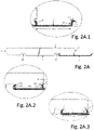
- FIG. 2A shows a panel (1) of such a set of panels, with a locking profile (3) clamped thereon.
- Each panel of the set of panels has a bottom surface (4), a top surface (5) - preferably finished with a decor and/or a wear layer, not shown in the figures - and a plurality of edges extending between the bottom and top surfaces.
- the panels are rectangular shaped with a pair of parallel longitudinal (long) edges (6-7) and a pair of parallel transversal (short) edges (8-9).
- a groove is provided in the bottom surface (4) of each panel, a first groove (10) extending parallel to and along the first edge (6) over the entire length of the panel and a second groove (11) extending parallel to and along the second edge (7).
- the first groove (10) is partially delimited by a sidewall or abutment surface (12) that at least partially extends slanting in view of the direction normal to the bottom surface (4) such that this sidewall inclines towards the first edge of the panel in a direction from the bottom surface (4) towards the top surface (5) of the panel and as such defines a wedge shaped section (13) in the panel between this sidewall (12) and the first edge (6).
- this sidewall (12) comprises two wall parts, a first wall part (12.1), most proximate to the bottom surface (4) of the panel extending substantially parallel to the direction normal to the bottom surface (4) and a second wall part (12.2) slanting in view of the first wall part (12.1) to define the wedge shaped section (13) as described supra.
- the first panel (1) further comprises a recess (14) provided in the first edge (6) that in this case is delimited by a sidewall (15) comprising a first part (15.1), most proximate to the bottom surface (4) of the panel extending substantially parallel to the direction normal to the bottom surface (4) and a second wall part (15.2) slanting in view of the first wall part inclined towards the second edge (7) of the panel in a direction from the bottom surface (4) towards the top surface (5) of the panel and as such defines the wedge shaped section (13) in the panel between the first edge (6) and the first groove (10).
- a sidewall comprising a first part (15.1), most proximate to the bottom surface (4) of the panel extending substantially parallel to the direction normal to the bottom surface (4) and a second wall part (15.2) slanting in view of the first wall part inclined towards the second edge (7) of the panel in a direction from the bottom surface (4) towards the top surface (5) of the panel and as such defines the wedge shaped section (13) in the panel
- the locking profile (3) comprises a base (16) and at least three protruding rims (17, 18, 19) extending parallel to one another in the longitudinal direction of the locking profile (3).
- a first rim (17) is lodged in the first groove (10) along the first edge (6) of the first panel and a third rim (19) that, in an assembled state of the set of panels, is lodged in the second groove (11) along the second edge (7) of the second panel.
- the second rim (18) is situated in the recess (14) provided in the first edge (6) of the first panel (1).
- both the first rim (17) and the second rim (18) are continuous and extends over the entire length of the locking profile (3).
- the third rims (17, 19) is continuous and extends over the entire length of the locking profile (3).
- the first rim (17) of the locking profile (3) preferably comprises two parts: a first part (17.1), most proximate to the base (16), extending in a direction substantially normal to the bottom surface (4) of the panel (1) when the locking profile (3) is clamped thereon; and a second part (17.2), most distant from the base (16) that is inclined in view of the first part (17.1) towards the second rim (18) over an angle ⁇ ranging between 50° and 90°, preferably between 60° and 70°.
- the first and second parts (17.1 and 17.2) of the first rim (17) thereby cooperate with, respectively, the first wall part (12.1) and second wall part (12.2) of the first groove (10).
- the second rim (18) of the locking profile (3) preferably comprises two parts: a first part (18.1), most proximate to the base (16), extending in a direction substantially normal to the bottom surface (4) of the panel when the locking profile (3) is clamped thereon; and a second part (18.2), most distant from the base (16) that is inclined in view of the first part (18.1) towards the first rim (17) over an angle ⁇ ranging between 60° and 80°, preferably between 65° and 75°.
- the first and second parts (18.1 and 18.2) of the second rim (18) thereby cooperate with, respectively, the first wall part (15.1) and second wall part (15.2) of the recess (14).
- first groove (10) and recess (14) of the first panel (1) and of the first and second rims (17, 18) of the locking profile (3) allows obtaining a strong and fail-proof clamping of the locking profile (3) on the first panel (1), whereby accidental release of the locking profile (3) is prevented.
- the third rim (19) of the locking profile (3) preferably comprises two parts: a first part (19.1), most proximate to the base (16) of the locking profile (3); and a second part (19.2), most distant from the base (16).
- the first part (19.1) is inclined away from the second rim (18) over an angle ⁇ with the base (16) of the locking profile (3) of at least 75°, preferably between 80°-90°, most preferably between 80°-86°.
- any or all can be designed as a rim extending in a same direction over its entire height, in which case this direction is preferably inclined at angles ⁇ , ⁇ and ⁇ respectively as described hereinabove.
- the locking profile (3) is an extruded profile manufactured in a plastic material (e.g. a glass-fiber reinforced plastic material, such as polystyrene) or preferably, in a metal material such as aluminum.
- a plastic material e.g. a glass-fiber reinforced plastic material, such as polystyrene
- a metal material such as aluminum
- the first panel (1) is positioned in place, with its bottom surface (4) and the base (16) of the locking profile (3) resting on a support surface (not shown). In this position, the part of the locking profile (3) between the second rim (18) and the third rim (19) is exposed and ready to receive an edge portion of the second panel (2).
- the third rim (19) of the locking profile is pressed in the second groove (11) of the second panel (2) such that it firmly contacts a sidewall (20) of that second groove (11) most proximate to the second edge (7) of the second panel and thereby locks the second panel from moving in view of the first panel in a direction perpendicular to the first and second edges (6, 7) of the first and second panels (1, 2) in the plane of the bottom surfaces (4) of both panels (1, 2).
- Such locking is commonly addressed as a horizontal lock between the panels.
- the strength of the horizontal lock defined as the force needed to tear both panels apart in the direction perpendicular to the first and second edges (6, 7) of the first and second panels (1, 2) in the plane of the bottom surfaces (4) of both panels (1, 2), is apart from material failure of the panels, dependent on the strength of the locking profile.
- a locking strength F MAX of at least 3 kN/m can be achieved when measured according to ISO24334 (2006), more preferably at least 4 kN/m.
- the thickness of the base (16) and the rims (17, 18, 19) preferably ranges between 0,4 mm and 1,2 mm, preferably between 0,5 mm and 0,8 mm. In some embodiments of the locking profile as explained further, the first and/or second rim may deviate from these ranges.
- the thickness of the base (16) of the locking profile (3) may vary between a first section (16.1) extending between the first rim (17) and the second rim (18) and a second section (16.2) extending between the second rim (18) and third rim (19).
- the thickness is preferably chosen to allow elastic bending of the locking profile (3) as shown in figure 7B while yet providing sufficient stretch resistance, this to allow easy assembly of the set of panels (1,2) by inserting the second edge (7) of the second panel (2) between the second and third rims (17, 18) of the locking profile (3), whereas the thickness of the first section (16.1) is preferably chosen to provide a desired clamping of the locking profile (3) on the first panel (1).
- the locking profiles (3) are preferably manufactured by extrusion. Once extruded, the locking profiles (3) are cut to a desired length, whereafter the cutted profiles (3) are stacked by positioning a plurality of locking profiles in a first orientation parallel to one another to create a first layer of locking profiles (3) and subsequently positioning a plurality of locking profiles in a second orientation parallel to one another and perpendicular to the first orientation to create a second layer of locking profiles (3) on top of the first layer of locking profiles.
- a third layer of locking profiles (3) positioned in the first orientation can subsequently be placed on the second layer of locking profiles and so on, thereby obtaining a cross-stack (21) of locking profiles (3) shown in figure 3A .
- the locking profiles (3) are subsequently destacked and positioned parallel to one another and in a predetermined position on a conveyor for feeding the locking profiles (3) one by one to a panel-assembly apparatus.
- one locking profile (3) is first aligned with the first edge (6) of a first panel (1) by positioning the second rim (18) of the locking profile (3) against the first edge (6), preferably against sidewall (15) of the first edge (6), of the first panel (1).
- the locking profile (3) is pressed against the bottom surface (4) of the panel (1), thereby pressing the first rim (17) of the locking profile (3) in the first groove (10) of the first panel (1).
- This pressing operation is preferably performed by guiding a first press-roll (22) over the locking profile (3).
- the first rim (17) of the locking profile (3) is at least partially bent by pressing the first rim (17) firmly against the abutment or sidewall surface (12) of the first groove (10) thereby ensuring that the wedge-shaped section (13) of the first panel (1) is adequately clamped between the first and second rim (17, 18) of the concerning locking profile (3).
- This pressing is preferably performed by a second press-roll assembly (23) which preferably presses a second part (17.2) of the first rim (17) firmly against or even partially into second wall part (12.2).
- the first rim (17) of the locking profile (3) when extruded, is configured to allow bending the first rim (17) towards the second rim (18), for clamping said locking profile (3) on a panel (1), while still providing sufficient resistance against bending the first rim (17) backwards such that the tensile strength of the locking profile (3), measured in the plane of the base (16) of the locking profile (3) is at least 3 kN/m measured in accordance with ISO24334(2006), preferably at least 4 kN/m.
- the first rim (17) is permanently deformed by the bending operation.
- heat may be applied to the first rim (17) just before, during or after bending the first rim (17) to make the deformation of the first rim permanent thereby ensuring clamping of the locking profile (3) on a panel (1).
- Figures 4-6 represent alternative embodiments of a locking profile (3) of the set of panels according to the present invention.
- the locking profile (3) shown in Figure 4 comprises a base (16) and three protruding rims (17, 18, 19) extending parallel to one another in the longitudinal direction of the locking profile (3).
- This protrusion (24) positioned at a distance from the base (16) of the locking profile (3), facilitating clamping the locking profile (3) on the first panel (1) as the inclined second part (17.2) of the first rim (17) of the locking profile described with reference to figure 2A .
- the locking profile shown in Figure 5 comprises a base (16) and three protruding rims (17, 18, 19) extending parallel to one another in the longitudinal direction of the locking profile (3).
- the second rim (18) comprises a first wing (25) and a second wing (26).
- the first wing (25) is inclined towards the first rim (17) of the locking profile (3) and has the same function of clamping the locking profile (3) on the first panel (1) as the inclined second part (18.2) of the second rim (18) of the locking profile described with reference to Figure 2A .
- the second wing (26) is inclined towards the third rim (19) and as such defines a groove (27) between the base (16) of the locking profile (3), the second rim (18) and the second wing (26).
- the second edge (7) of each panel comprises a recess (28) configured to accommodate the second wing (26).
- the locking profile (3) shown in Figure 6 comprises a base (16) and three protruding rims (17, 18, 19) extending parallel to one another in the longitudinal direction of the locking profile (3).
- the second rim (18) is designed as a composite rim having two or more parallel and spaced apart rims (181, 182) or else can be described as a rim (18) having a central void.
- both spaced apart rims (181 and 182) comprise a wing.
- the first spaced apart rim (181), situated most proximate to the first rim (17), comprises a wing (25) that is inclined towards the first rim (17) of the locking profile (3).
- This rim (181) has the same function as the second rim (18) of the locking profile described with reference to figure 2B .
- the second spaced apart rim (182) located most distant from the first rim (17) comprises a second wing (26), inclined towards the third rim (19) and as such defines a groove (27) between the base (16) of the locking profile (3), the second rim (18) and the second wing (26).
- a slot (30) comprising in this case a female snap-fit locking means (31), wherein a spacer (32) having a corresponding male snap-fit locking means (33) is disposed.
- the spacer is positioned between the facing edges (6, 7) of the first and second panels (1,2) locked by the locking profile.
- the locking between spacer (32) and locking profile (3) can be executed in accordance with a multitude of alternatives without departing from the present invention as defined in the appended claims.
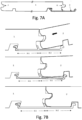
- FIG 7A and 7B an assembly of panels is shown that differs from the embodiment of Figure 2A in that the first and second edges (6, 7) of the panels (1, 2) are configured as a tongue and groove system allowing vertically locking both panels once assembled.
- the tongue is provided on the first edge (6) of the first panel (1), while the groove is provided in the second edge (7) of the second panel (2), yet clearly it is also possible to provide the tongue on the second edge (7) of the second panel (2) and to provide the groove in the first edge (6) of the first panel (1).
- the thickness of the base (16) of the locking profile may vary between a first section (16.1) extending between the first rim (17) and second rim (18) and a second section (16.2) extending between the second rim (18) and the third rim (19).
- the thickness is preferably chosen to allow elastic bending of the locking profile (3) as shown in figure 7B while yet providing sufficient stretch resistance, this to allow easy assembly of the set of panels (1, 2) by inserting the second edge (7) of the second panel (2) between the second and third rims (18, 19) of the locking profile (3), whereas the thickness of the first section (16.1) is preferably chosen to provide a desired clamping of the locking profile (3) on the first panel (1).
- first and second edges (6 and 7), without limitation to the shape of the panels and without specifying, in case the panels are rectangular, whether the concerned first and second edges are longitudinal edges (long edges) or transversal edges (short edges). It is therefore clear that for the above description, no limitation to position or length of the pair of parallel edges was intended.
- each panel comprises in addition to the above first and second edges (6, 7) and the corresponding locking profile (3):
- the locking profile disposed at a long side of the panel is allowed to extend into the corner region defined by the first and third edges of the panel, whereas the locking profile disposed at the short edge of the panel does not extend into that corner portion or vice versa.
- the minimum and maximum length of the locking profile disposed along a single side of a panel there is no real limit on the minimum and maximum length of the locking profile disposed along a single side of a panel and lengths varying from 5 cm up to several meters can be envisaged.
- the locking profile has a length that is a multitude smaller than the length of the side on which it is disposed, a plurality of locking profiles is disposed on that same edge of the panel, with the sum of the lengths of the locking profiles disposed on that edge being equal to or larger than at least 80% of the total length of the concerned side edge.
- the panels can be be made from many different materials or combinations of materials as long as it is feasible to make the retaining profiles as described hereinbefore, on their edges.
- the panels may be wood-based (e.g. solid wood, a fiberboard (MDF, HDF), or a particle board).
- the panels may also be made of, or at least comprising a layer of, synthetic material.
- synthetic material as used in the context of the current invention can be a single polymer or a blend of two or more polymers.
- the synthetic material can be, for example, a thermoplastic polymer, a thermosetting polymer, a rubber (elastomer), or any combinations thereof.
- the polymeric material is a thermoplastic polymer that includes vinyl containing thermoplastics such as polyvinyl chloride, polyvinyl acetate, polyvinyl alcohol, and other vinyl and vinylidene resins and copolymers thereof; polyethylenes such as low density polyethylenes and high density polyethylenes and copolymers thereof; styrenes such as ABS, SAN, and polystyrenes and copolymers thereof, polypropylene and copolymers thereof; saturated and unsaturated polyesters; acrylics; polyamides such as nylon containing types; engineering plastics such as polycarbonate, polyimide, polysulfone, and polyphenylene oxide and sulfide resins and the like.
- the synthetic material compound used to form the panel or a layer thereof can be a PVC powder compound that has good impact strength, ease of processing, high extrusion rate, good surface properties, excellent dimensional stability, and indentation resistance.
- the panels may also comprise composite materials, or one or more layers thereof, such as wood-plastic composites (WPC), referring to a composite structure comprising a wood- based material and a synthetic material.
- WPC wood-plastic composites
- the panel may comprise multiple layers which can be identical or different with respect to composition and/or physical properties.
Landscapes
- Engineering & Computer Science (AREA)
- Architecture (AREA)
- Civil Engineering (AREA)
- Structural Engineering (AREA)
- Life Sciences & Earth Sciences (AREA)
- Wood Science & Technology (AREA)
- Finishing Walls (AREA)
- Roof Covering Using Slabs Or Stiff Sheets (AREA)
- Floor Finish (AREA)
Description
- The invention generally relates to the field of sets of panels for covering floors, ceilings or walls, in particular sets of panels comprising a plurality of panels to be joined at their adjacent edges.
- Building panels and in particular floorings used in highly frequented and heavy load environments necessarily need strong locking to prevent opening of the locked edges between two adjacent panels. It is known for such floorings to provide a locking system comprising a locking profile provided to one of the panels along the adjacent edges, wherein said locking profile is manufactured in either plastic materials or a metal material such as aluminum.
- To date and as disclosed in
WO98/24994 WO98/24995 - A first drawback of the method and locking mechanism disclosed in the prior art is that mechanically fixing the locking profiles to panels is a very slow process slowing down the entire production process of the panels. Another drawback is that the punching of metal sheets is a slow process providing only very limited design options and requiring large capex for each variation in the design of the locking profiles. Further improvements of this locking system have therefore been rare.
-
WO2015/005860 andUS2009/0151290 disclose other embodiments of locking profiles comprising non-continuous rims for fixation of the locking profile to the panels. Such locking profiles having the same drawbacks as the ones described supra.WO00/20706 EP2492416 disclose sets of panels locked to one another by locking profiles having rims interacting with the panels over a larger extent of the panel length, however these locking profiles are manufactured in a (highly) flexible polymeric material that does not allow a high strength fixation of the panels to one another and hence are not suitable for eg. heavy duty flooring systems. - It is however an object of the present invention to further improve this locking system.
- In a first aspect, the present invention relates to a set of panels (1,2), each panel comprising:
- a top surface (5) and a bottom surface (4);
- a first edge (6) and a second edge (7) parallel to the first edge (6), said edges (6, 7) extending between said top and bottom surfaces (5, 4);
- a first groove (10) provided in the bottom surface (4) of each panel, said first groove (10) extending parallel to and along the first edge (6) of the panel;
- a second groove (11) provided in the bottom surface (4) of each panel, said second groove (11) extending parallel to the first groove (10) along the second edge (7) of the panel;
- In contrast to the general assumptions in the business of flooring (cf.
WO94/26999 - In particular, the Applicant has discovered that by manufacturing the locking profile with a continuous second rim, the angles of the rims of the locking profile interacting with the panels can be designed such as to strongly increase the locking strength when compared to locking profiles made of punched metal sheets and that, apart from the increased strength, the locking between adjacent panels with the locking profile according to the invention provides an improved stability of the lock.
- As illustrated in
figure 1A , showing a partial view of the bottom side of two assembled panels with a locking profile according to the prior art and infigure 1B , showing a similar view with a locking profile according to the present invention, the present invention does not necessitate a partial damaging (punching) of the locking profile. - The preferred method of manufacturing the locking profile of the set of panels according to the present invention is by extrusion.
- In a second aspect, the present invention relates to method of manufacturing a set of panels (1, 2), the method comprising:
- a. providing a first panel (1) having:
- a top surface (5) and a bottom surface (4);
- a first edge (6) and a second edge (7) parallel to the first edge (6), said edges (6, 7) extending between said top and bottom surfaces (5, 4);
- a first groove (10) provided in the bottom surface (4) of each panel (1, 2), said first groove (10) extending parallel to and along the first edge (6) of the panel;
- a second groove (11) provided in the bottom surface (4) of each panel (1, 2), said second groove (11) extending parallel to the first groove (10) along the second edge (7) of the panel;
- b. providing a locking profile (3) comprising a base (16) and at least three protruding rims (17, 18, 19) extending parallel to one another in the longitudinal direction of the locking profile (3), wherein at least a first rim (17) and a second rim (18) -situated between a first rim (17) and a third rim (19)- are continuous along the entire length of the locking profile (3);
- c. positioning the second rim (18) of the locking profile (3) against an abutment surface (15) of the first panel (1);
- d. pressing the first rim (17) of said locking profile (3) in the first groove (10) of the first panel (1), such that a section (13) of the panel is clamped between the first rim (17) and the second rim (18) of the locking profile (3);
- e. permanently deforming the first rim (17) of the locking profile (3) by bending it in the direction of the second rim (18) after having pressed the first rim (17) in the first groove (10) of the first panel (1), whereby_the first groove (10) defines an abutment surface (12) for the first rim (17), which abutment surface (12) is angled in view of the bottom surface (4) such that the section (13) of the first panel (1) clamped between the first rim (17) and the second rim (18) of the locking profile increases in width towards the bottom surface of the panel (1).
- In a third aspect, the present invention relates to an assembly of panels comprising a set of panels (1, 2) as defined in any of claims 1-12.
-
-
Figure 1A shows a picture of a partial view of the bottom side of two assembled panels with a locking profile according to the prior art; -
Figure 1B shows a picture of a partial view of the bottom side of two assembled panels with a locking profile according to the present invention; -
Figure 2A schematically represents a first panel of the set of panels of the present invention and with -
Figures 2A.1, 2A.2 and 2A.3 representing in more detail some specific parts of the first panel and locking profile provided on the first panel as represented inFigure 2A ; -
Figure 2B schematically shows a method of assembling a set of panels according to the present invention; -
Figures 3A-C schematically represent a method of manufacturing a set of panels according to the present invention; -
Figures 4, 5A and 6 show a cross-section of locking profiles according to alternative embodiments of the present invention; -
Figure 5B shows the locking profile ofFigure 5A when provided on a first panel and ready to cooperate with a second panel; -
Figure 7A and 7B show an alternative embodiment offigures 2A and2B respectively; -
Figures 8 and 9 show a panel according to the present invention with two alternative configurations for clamping multiple locking profiles thereon. - The present invention concerns a set of panels, typically for covering floors, ceilings or walls.
-
Figure 2A shows a panel (1) of such a set of panels, with a locking profile (3) clamped thereon. Each panel of the set of panels has a bottom surface (4), a top surface (5) - preferably finished with a decor and/or a wear layer, not shown in the figures - and a plurality of edges extending between the bottom and top surfaces. - In the embodiment represented in
figure 2A , the panels are rectangular shaped with a pair of parallel longitudinal (long) edges (6-7) and a pair of parallel transversal (short) edges (8-9). Along each longitudinal edge (6, 7) a groove is provided in the bottom surface (4) of each panel, a first groove (10) extending parallel to and along the first edge (6) over the entire length of the panel and a second groove (11) extending parallel to and along the second edge (7). - At its side most proximate to the first edge (6) of the panel, the first groove (10) is partially delimited by a sidewall or abutment surface (12) that at least partially extends slanting in view of the direction normal to the bottom surface (4) such that this sidewall inclines towards the first edge of the panel in a direction from the bottom surface (4) towards the top surface (5) of the panel and as such defines a wedge shaped section (13) in the panel between this sidewall (12) and the first edge (6). In the embodiment represented in
Figure 2B , this sidewall (12) comprises two wall parts, a first wall part (12.1), most proximate to the bottom surface (4) of the panel extending substantially parallel to the direction normal to the bottom surface (4) and a second wall part (12.2) slanting in view of the first wall part (12.1) to define the wedge shaped section (13) as described supra. - Preferably, the first panel (1) further comprises a recess (14) provided in the first edge (6) that in this case is delimited by a sidewall (15) comprising a first part (15.1), most proximate to the bottom surface (4) of the panel extending substantially parallel to the direction normal to the bottom surface (4) and a second wall part (15.2) slanting in view of the first wall part inclined towards the second edge (7) of the panel in a direction from the bottom surface (4) towards the top surface (5) of the panel and as such defines the wedge shaped section (13) in the panel between the first edge (6) and the first groove (10).
- As shown in
figure 2B , two panels of the set of panels are coupled to one another along their facing longitudinal edges (6, 7) by means of the locking profile (3). The locking profile (3) comprises a base (16) and at least three protruding rims (17, 18, 19) extending parallel to one another in the longitudinal direction of the locking profile (3). A first rim (17) is lodged in the first groove (10) along the first edge (6) of the first panel and a third rim (19) that, in an assembled state of the set of panels, is lodged in the second groove (11) along the second edge (7) of the second panel. The second rim (18), situated between the first and third rims of the locking profile (3), cooperates with a part of the first edge (6) of the first panel (1), such that a section of the first panel (1) is clamped between the first and second rims (17, 18) of the locking profile. In the embodiment represented infigure 2B , the second rim (18) is situated in the recess (14) provided in the first edge (6) of the first panel (1). - According to the present invention, both the first rim (17) and the second rim (18) are continuous and extends over the entire length of the locking profile (3). Preferably also the third rims (17, 19) is continuous and extends over the entire length of the locking profile (3).
- As represented in
figure 2B , the first rim (17) of the locking profile (3) preferably comprises two parts: a first part (17.1), most proximate to the base (16), extending in a direction substantially normal to the bottom surface (4) of the panel (1) when the locking profile (3) is clamped thereon; and a second part (17.2), most distant from the base (16) that is inclined in view of the first part (17.1) towards the second rim (18) over an angle α ranging between 50° and 90°, preferably between 60° and 70°. When the locking profile (3) is clamped on the first panel (1), the first and second parts (17.1 and 17.2) of the first rim (17) thereby cooperate with, respectively, the first wall part (12.1) and second wall part (12.2) of the first groove (10). The second rim (18) of the locking profile (3) preferably comprises two parts: a first part (18.1), most proximate to the base (16), extending in a direction substantially normal to the bottom surface (4) of the panel when the locking profile (3) is clamped thereon; and a second part (18.2), most distant from the base (16) that is inclined in view of the first part (18.1) towards the first rim (17) over an angle β ranging between 60° and 80°, preferably between 65° and 75°. When the locking profile (3) is clamped on the first panel (1), the first and second parts (18.1 and 18.2) of the second rim (18) thereby cooperate with, respectively, the first wall part (15.1) and second wall part (15.2) of the recess (14). The above specific design of the first groove (10) and recess (14) of the first panel (1) and of the first and second rims (17, 18) of the locking profile (3) allows obtaining a strong and fail-proof clamping of the locking profile (3) on the first panel (1), whereby accidental release of the locking profile (3) is prevented. - The third rim (19) of the locking profile (3) preferably comprises two parts: a first part (19.1), most proximate to the base (16) of the locking profile (3); and a second part (19.2), most distant from the base (16). The first part (19.1) is inclined away from the second rim (18) over an angle γ with the base (16) of the locking profile (3) of at least 75°, preferably between 80°-90°, most preferably between 80°-86°.
- Alternative to the two part designs of the first, second and third rims (17, 18, 19), any or all can be designed as a rim extending in a same direction over its entire height, in which case this direction is preferably inclined at angles α, β and γ respectively as described hereinabove.
- Preferably, the locking profile (3) is an extruded profile manufactured in a plastic material (e.g. a glass-fiber reinforced plastic material, such as polystyrene) or preferably, in a metal material such as aluminum.
- In order to assemble the set of panels (1, 2) and as represented in
Figure 2B , the first panel (1) is positioned in place, with its bottom surface (4) and the base (16) of the locking profile (3) resting on a support surface (not shown). In this position, the part of the locking profile (3) between the second rim (18) and the third rim (19) is exposed and ready to receive an edge portion of the second panel (2). By positioning the second edge (7) of the second panel (2) against the first edge (6) of the first panel (1) and subsequently pressing the second panel (2) towards the support surface, the third rim (19) of the locking profile is pressed in the second groove (11) of the second panel (2) such that it firmly contacts a sidewall (20) of that second groove (11) most proximate to the second edge (7) of the second panel and thereby locks the second panel from moving in view of the first panel in a direction perpendicular to the first and second edges (6, 7) of the first and second panels (1, 2) in the plane of the bottom surfaces (4) of both panels (1, 2). Such locking is commonly addressed as a horizontal lock between the panels. - The strength of the horizontal lock, defined as the force needed to tear both panels apart in the direction perpendicular to the first and second edges (6, 7) of the first and second panels (1, 2) in the plane of the bottom surfaces (4) of both panels (1, 2), is apart from material failure of the panels, dependent on the strength of the locking profile.
- When manufacturing the locking profile in aluminum and with a base having a thickness of at least 0,4 mm, for example 0,6 mm, a locking strength FMAX of at least 3 kN/m can be achieved when measured according to ISO24334 (2006), more preferably at least 4 kN/m.
- The thickness of the base (16) and the rims (17, 18, 19) preferably ranges between 0,4 mm and 1,2 mm, preferably between 0,5 mm and 0,8 mm. In some embodiments of the locking profile as explained further, the first and/or second rim may deviate from these ranges.
- In addition hereto it is mentioned that the thickness of the base (16) of the locking profile (3) may vary between a first section (16.1) extending between the first rim (17) and the second rim (18) and a second section (16.2) extending between the second rim (18) and third rim (19).
- For the second section (16.2) the thickness is preferably chosen to allow elastic bending of the locking profile (3) as shown in
figure 7B while yet providing sufficient stretch resistance, this to allow easy assembly of the set of panels (1,2) by inserting the second edge (7) of the second panel (2) between the second and third rims (17, 18) of the locking profile (3), whereas the thickness of the first section (16.1) is preferably chosen to provide a desired clamping of the locking profile (3) on the first panel (1). - As mentioned supra the locking profiles (3) are preferably manufactured by extrusion. Once extruded, the locking profiles (3) are cut to a desired length, whereafter the cutted profiles (3) are stacked by positioning a plurality of locking profiles in a first orientation parallel to one another to create a first layer of locking profiles (3) and subsequently positioning a plurality of locking profiles in a second orientation parallel to one another and perpendicular to the first orientation to create a second layer of locking profiles (3) on top of the first layer of locking profiles. A third layer of locking profiles (3) positioned in the first orientation can subsequently be placed on the second layer of locking profiles and so on, thereby obtaining a cross-stack (21) of locking profiles (3) shown in
figure 3A . - As schematically represented in
figure 3A , the locking profiles (3) are subsequently destacked and positioned parallel to one another and in a predetermined position on a conveyor for feeding the locking profiles (3) one by one to a panel-assembly apparatus. In the panel-assembly apparatus, as represented inFigure 3B , one locking profile (3) is first aligned with the first edge (6) of a first panel (1) by positioning the second rim (18) of the locking profile (3) against the first edge (6), preferably against sidewall (15) of the first edge (6), of the first panel (1). Subsequently and as shown inFigure 3C , the locking profile (3) is pressed against the bottom surface (4) of the panel (1), thereby pressing the first rim (17) of the locking profile (3) in the first groove (10) of the first panel (1). This pressing operation is preferably performed by guiding a first press-roll (22) over the locking profile (3). - Subsequently, as represented in
figure 3D , the first rim (17) of the locking profile (3) is at least partially bent by pressing the first rim (17) firmly against the abutment or sidewall surface (12) of the first groove (10) thereby ensuring that the wedge-shaped section (13) of the first panel (1) is adequately clamped between the first and second rim (17, 18) of the concerning locking profile (3). This pressing is preferably performed by a second press-roll assembly (23) which preferably presses a second part (17.2) of the first rim (17) firmly against or even partially into second wall part (12.2). - It is preferred that the first rim (17) of the locking profile (3), when extruded, is configured to allow bending the first rim (17) towards the second rim (18), for clamping said locking profile (3) on a panel (1), while still providing sufficient resistance against bending the first rim (17) backwards such that the tensile strength of the locking profile (3), measured in the plane of the base (16) of the locking profile (3) is at least 3 kN/m measured in accordance with ISO24334(2006), preferably at least 4 kN/m.
- According to the present invention, the first rim (17) is permanently deformed by the bending operation. In case the locking profile is manufactured in a plastic material, heat may be applied to the first rim (17) just before, during or after bending the first rim (17) to make the deformation of the first rim permanent thereby ensuring clamping of the locking profile (3) on a panel (1).
-
Figures 4-6 represent alternative embodiments of a locking profile (3) of the set of panels according to the present invention. - The locking profile (3) shown in
Figure 4 , comprises a base (16) and three protruding rims (17, 18, 19) extending parallel to one another in the longitudinal direction of the locking profile (3). The first rim (17) configured to be lodged in the first groove (10) along the first edge (6) of the first panel (1), in this case comprises a protrusion (24) protruding from the first rim (17) in the direction of the second rim (18). This protrusion (24), positioned at a distance from the base (16) of the locking profile (3), facilitating clamping the locking profile (3) on the first panel (1) as the inclined second part (17.2) of the first rim (17) of the locking profile described with reference tofigure 2A . - The locking profile shown in
Figure 5 , comprises a base (16) and three protruding rims (17, 18, 19) extending parallel to one another in the longitudinal direction of the locking profile (3). In this embodiment, the second rim (18) comprises a first wing (25) and a second wing (26). - The first wing (25) is inclined towards the first rim (17) of the locking profile (3) and has the same function of clamping the locking profile (3) on the first panel (1) as the inclined second part (18.2) of the second rim (18) of the locking profile described with reference to
Figure 2A . The second wing (26) is inclined towards the third rim (19) and as such defines a groove (27) between the base (16) of the locking profile (3), the second rim (18) and the second wing (26). In this embodiment, the second edge (7) of each panel comprises a recess (28) configured to accommodate the second wing (26). This design of the locking profile (3) and the second edge (7) of the panels prevents a movement between the first and second panels (1,2) in a direction normal to the bottom surfaces of the panels (commonly referred to as a vertical lock). - The locking profile (3) shown in
Figure 6 , comprises a base (16) and three protruding rims (17, 18, 19) extending parallel to one another in the longitudinal direction of the locking profile (3). In this case, the second rim (18) is designed as a composite rim having two or more parallel and spaced apart rims (181, 182) or else can be described as a rim (18) having a central void. - In this case both spaced apart rims (181 and 182) comprise a wing. The first spaced apart rim (181), situated most proximate to the first rim (17), comprises a wing (25) that is inclined towards the first rim (17) of the locking profile (3). This rim (181) has the same function as the second rim (18) of the locking profile described with reference to
figure 2B . The second spaced apart rim (182) located most distant from the first rim (17) comprises a second wing (26), inclined towards the third rim (19) and as such defines a groove (27) between the base (16) of the locking profile (3), the second rim (18) and the second wing (26). Between both spaced apart rims (181) and (182) is a slot (30) comprising in this case a female snap-fit locking means (31), wherein a spacer (32) having a corresponding male snap-fit locking means (33) is disposed. The spacer is positioned between the facing edges (6, 7) of the first and second panels (1,2) locked by the locking profile. Clearly, the locking between spacer (32) and locking profile (3) can be executed in accordance with a multitude of alternatives without departing from the present invention as defined in the appended claims. - In
Figure 7A and 7B an assembly of panels is shown that differs from the embodiment ofFigure 2A in that the first and second edges (6, 7) of the panels (1, 2) are configured as a tongue and groove system allowing vertically locking both panels once assembled. - In the represented embodiment, the tongue is provided on the first edge (6) of the first panel (1), while the groove is provided in the second edge (7) of the second panel (2), yet clearly it is also possible to provide the tongue on the second edge (7) of the second panel (2) and to provide the groove in the first edge (6) of the first panel (1).
- Further it is mentioned that the thickness of the base (16) of the locking profile may vary between a first section (16.1) extending between the first rim (17) and second rim (18) and a second section (16.2) extending between the second rim (18) and the third rim (19).
- For the second section (16.2) the thickness is preferably chosen to allow elastic bending of the locking profile (3) as shown in
figure 7B while yet providing sufficient stretch resistance, this to allow easy assembly of the set of panels (1, 2) by inserting the second edge (7) of the second panel (2) between the second and third rims (18, 19) of the locking profile (3), whereas the thickness of the first section (16.1) is preferably chosen to provide a desired clamping of the locking profile (3) on the first panel (1). - With respect to the detailed description of the invention here above, the facing edges of two adjacent panels have been addressed by the first and second edges (6 and 7), without limitation to the shape of the panels and without specifying, in case the panels are rectangular, whether the concerned first and second edges are longitudinal edges (long edges) or transversal edges (short edges). It is therefore clear that for the above description, no limitation to position or length of the pair of parallel edges was intended.
- Now, in some cases it is desirable to provide locking profiles on more than one pair of facing edges of adjacent panels. As represented in
figures 8 and 9 , each panel comprises in addition to the above first and second edges (6, 7) and the corresponding locking profile (3): - a third edge (8) and a fourth edge (9) parallel to the third edge (8), said edges extending between the top surface (5) and bottom surface (4) of the panel (1);
- a third groove (34) provided in the bottom surface (4) of each panel, said third groove (34) extending parallel to and along the third edge (8) of the panel (1);
- a fourth groove (35) provided in the bottom surface (4) of each panel, said fourth groove (35) extending parallel to the third groove (34) along the fourth edge (9) of the panel (1);
- a second locking profile (36) allowing locking a first panel (1) with its third edge (8) to the fourth edge (9) of a third panel, said second locking profile (36) comprising a base (16) and at least three protruding rims (17, 18, 19) extending parallel to one another in the longitudinal direction of the locking profile (36), a first rim (17) disposed in the third groove (34) of a first panel (1) and a second rim (18) situated in between the first and third rims (17, 19) of each second locking profile (36) and cooperating with a part of the first panel (1) such that a section (13) of the first panel (1) is clamped between the first rim (17) and the second rim (18) of the second locking profile (36), the third rim (18) configured to fit in the fourth groove (35) of a third panel thereby locking the third panel to the first panel (1), wherein at least the second rim (18) of the second locking profile (36) is continuous along the entire length of said second locking profile (36).
- In such a configuration, overlapping locking profiles are to be prevented. Therefore it is preferred that the locking profile disposed at a long side of the panel is allowed to extend into the corner region defined by the first and third edges of the panel, whereas the locking profile disposed at the short edge of the panel does not extend into that corner portion or vice versa.
- Further, according to the present invention there is no real limit on the minimum and maximum length of the locking profile disposed along a single side of a panel and lengths varying from 5 cm up to several meters can be envisaged. However, in order to obtain a rigid lock with sufficient FMAX locking strength, it is preferred that in case the locking profile has a length that is a multitude smaller than the length of the side on which it is disposed, a plurality of locking profiles is disposed on that same edge of the panel, with the sum of the lengths of the locking profiles disposed on that edge being equal to or larger than at least 80% of the total length of the concerned side edge.
- For all the above described embodiments, the panels can be be made from many different materials or combinations of materials as long as it is feasible to make the retaining profiles as described hereinbefore, on their edges.
- The panels may be wood-based (e.g. solid wood, a fiberboard (MDF, HDF), or a particle board). The panels may also be made of, or at least comprising a layer of, synthetic material. The term "synthetic material" as used in the context of the current invention can be a single polymer or a blend of two or more polymers. The synthetic material can be, for example, a thermoplastic polymer, a thermosetting polymer, a rubber (elastomer), or any combinations thereof. In one particular example, the polymeric material is a thermoplastic polymer that includes vinyl containing thermoplastics such as polyvinyl chloride, polyvinyl acetate, polyvinyl alcohol, and other vinyl and vinylidene resins and copolymers thereof; polyethylenes such as low density polyethylenes and high density polyethylenes and copolymers thereof; styrenes such as ABS, SAN, and polystyrenes and copolymers thereof, polypropylene and copolymers thereof; saturated and unsaturated polyesters; acrylics; polyamides such as nylon containing types; engineering plastics such as polycarbonate, polyimide, polysulfone, and polyphenylene oxide and sulfide resins and the like. The synthetic material compound used to form the panel or a layer thereof can be a PVC powder compound that has good impact strength, ease of processing, high extrusion rate, good surface properties, excellent dimensional stability, and indentation resistance.
- The panels may also comprise composite materials, or one or more layers thereof, such as wood-plastic composites (WPC), referring to a composite structure comprising a wood- based material and a synthetic material. The panel may comprise multiple layers which can be identical or different with respect to composition and/or physical properties.
Claims (12)
- A set of panels (1,2), each panel comprising:• a top surface (5) and a bottom surface (4);• a first edge (6) and a second edge (7) parallel to the first edge (6), said edges (6, 7) extending between said top and bottom surfaces (5, 4);• a first groove (10) provided in the bottom surface (4) of each panel, said first groove (10) extending parallel to and along the first edge (6) of the panel;• a second groove (11) provided in the bottom surface (4) of each panel, said second groove (11) extending parallel to the first groove (10) along the second edge (7) of the panel;• a locking profile (3) allowing locking a first panel (1) with its first edge (6) to the second edge (7) of a second panel (2), said locking profile (3) comprising a base (16) and at least three protruding rims (17, 18, 19) extending parallel to one another in the longitudinal direction of the locking profile (3), a first rim (17) pressed in the first groove (10) of a first panel (1) and a second rim (18) situated in between the first and third rims (17, 19) of each locking profile (3) and cooperating with a part of the first panel (1) such that a section (13) of the bottom surface (4) of the first panel (1) is permanently clamped between the first rim and the second rim (17, 18) of the locking profile (3), the third rim (19) configured to fit in the second groove (11) of a second panel (2) thereby locking the second panel (2) to the first panel (1), characterized in that at least the first rim (17) and the second rim (18) are continuous along the entire length of the locking profile (3), and in that the first groove (10) defines an abutment surface (12) for the first rim (17), which abutment surface (12) is angled in view of the bottom surface (4) such that the section (13) of the first panel (1) clamped between the first rim (17) and the second rim (18) of the locking profile (3) increases in width towards the bottom surface (4) of the panel (1).
- The set of panels (1, 2) according to claim 1, wherein said locking profile (3) is manufactured by extrusion.
- The set of panels (1, 2) according to claim 1 or 2, wherein said locking profile (3) is manufactured from a metal material, preferably aluminum.
- The set of panels (1, 2) according to any of the preceding claims, each panel comprising a recess (14) in its first edge (6), said recess (14) extending in the longitudinal direction of the first edge (6), said recess (14) at least partially accommodating the second rim (18) of the concerned locking profile (3).
- The set of panels (1, 2) according to any of the preceding claims, wherein said second rim (18) is inclined towards the first rim (17) of the locking profile (3).
- The set of panels (1, 2) according to any of the preceding claims, the second rim (18) comprising two wings (25, 26) at its free end, a first wing (25) inclined towards the first rim (17) of the locking profile (3) and extending into the recess (14) in the first edge (6), and a second wing (26) inclined towards the third rim (19) of the locking profile (3) and extending into a recess (28) provided along the second edge (7) of a second panel (2).
- The set of panels (1, 2) according to claims 1-5 6, wherein the second rim (18) of the locking profile (3) is a composed rim having two or more parallel and spaced apart rims (181, 182), preferably configured to accommodate a spacer (32) after locking the second panel (2) to the first panel (1) with a predefined distance between both panels (1, 2).
- The set of panels (1, 2) according to any of the preceding claims, wherein one or more locking profiles are provided along the first edge (6) of a first panel (1), said one or more locking profiles having a total length equal to or larger than 80% of the length of the first edge (6).
- The set of panels (1, 2) according to any of the preceding claims, said panels comprising:• a third edge (8) and a fourth edge (9) parallel to the third edge (8), said edges (8, 9) extending between the top surface (5) and bottom surface (4) of the panel (1);• a third groove (34) provided in the bottom surface (4) of each panel, said third groove (34) extending parallel to and along the third edge (8) of the panel (1);• a fourth groove (35) provided in the bottom surface (4) of each panel, said fourth groove (35) extending parallel to the third groove (34) along the fourth edge (9) of the panel (1);• a second locking profile (36) allowing locking a first panel (1) with its third edge (8) to the fourth edge (9) of a third panel, said second locking profile (36) comprising a base (16) and at least three protruding rims (17, 18, 19) extending parallel to one another in the longitudinal direction of the locking profile (36), a first rim (17) press-fitted in the third groove (34) of a first panel (1) and a second rim (18) situated in between the first and third rims (17, 19) of each second locking profile (36) and cooperating with a part of the first panel (1) such that a section of the bottom surface (4) of the first panel (1) is clamped between the first rim (17) and the second rim (18) of the second locking profile (36), the third rim (19) configured to fit in the fourth groove (35) of a third panel thereby locking the third panel to the first panel (1), wherein at least the second rim (18) of the second locking profile (36) is continuous along the entire length of said second locking profile (36).
- The set of panels according to any of the preceding claims, wherein the first and second edges (6, 7) are configured to define a tongue and groove system.
- A method of manufacturing a set of panels (1, 2), the method comprising:a. providing a first panel (1) having:• a top surface (5) and a bottom surface (4);• a first edge (6) and a second edge (7) parallel to the first edge (6), said edges (6, 7) extending between said top and bottom surfaces (5, 4);• a first groove (10) provided in the bottom surface (4) of each panel (1, 2), said first groove (10) extending parallel to and along the first edge (6) of the panel;• a second groove (11) provided in the bottom surface (4) of each panel (1, 2), said second groove (11) extending parallel to the first groove (10) along the second edge (7) of the panel;b. providing a locking profile (3) comprising a base (16) and at least three protruding rims (17, 18, 19) extending parallel to one another in the longitudinal direction of the locking profile (3), wherein at least a first rim (17) and a second rim (18) -situated between the first rim (17) and a third rim (19) - are continuous along the entire length of the locking profile (3);c. positioning the second rim (18) of the locking profile (3) against an abutment surface (15) of the first panel (1);d. pressing the first rim (17) of said locking profile (3) in the first groove (10) of the first panel (1), such that a section (13) of the panel is clamped between the first rim (17) and the second rim (18) of the locking profile (3); ande. permanently deforming the first rim (17) of the locking profile (3) by bending it in the direction of the second rim (18) after having pressed the first rim (17) in the first groove (10) of the first panel (1), whereby the first groove (10) defines an abutment surface (12) for the first rim (17), which abutment surface (12) is angled in view of the bottom surface (4) such that the section (13) of the first panel (1) clamped between the first rim (17) and the second rim (18) of the locking profile increases in width towards the bottom surface of the panel (1).
- An assembly of panels comprising a set of panels (1, 2) as defined in any of claims 1-10.
Applications Claiming Priority (2)
| Application Number | Priority Date | Filing Date | Title |
|---|---|---|---|
| EP16151625 | 2016-01-15 | ||
| PCT/EP2017/050669 WO2017121851A1 (en) | 2016-01-15 | 2017-01-13 | Set of panels, method for manufacturing such set of panels, assembly of the panels and locking profile used in said panels |
Publications (2)
| Publication Number | Publication Date |
|---|---|
| EP3402939A1 EP3402939A1 (en) | 2018-11-21 |
| EP3402939B1 true EP3402939B1 (en) | 2023-02-01 |
Family
ID=55177779
Family Applications (1)
| Application Number | Title | Priority Date | Filing Date |
|---|---|---|---|
| EP17700366.2A Active EP3402939B1 (en) | 2016-01-15 | 2017-01-13 | Set of panels with a locking strip, method for manufacturing such set of panels, and assembly of the panels |
Country Status (13)
| Country | Link |
|---|---|
| US (1) | US11486147B2 (en) |
| EP (1) | EP3402939B1 (en) |
| JP (1) | JP2019502045A (en) |
| CN (1) | CN108884679A (en) |
| CA (1) | CA3010903C (en) |
| DK (1) | DK3402939T3 (en) |
| ES (1) | ES2943065T3 (en) |
| FI (1) | FI3402939T3 (en) |
| HU (1) | HUE062077T2 (en) |
| LT (1) | LT3402939T (en) |
| PL (1) | PL3402939T3 (en) |
| RU (1) | RU2018127782A (en) |
| WO (1) | WO2017121851A1 (en) |
Families Citing this family (5)
| Publication number | Priority date | Publication date | Assignee | Title |
|---|---|---|---|---|
| WO2017185167A1 (en) * | 2016-04-26 | 2017-11-02 | Les Plafonds Embassy Inc. | Clip for suspended ceiling members |
| DE102017105146A1 (en) * | 2017-03-10 | 2018-09-13 | GKT Gummi- und Kunststofftechnik Fürstenwalde GmbH | Floorboard system |
| DE202018006668U1 (en) * | 2017-06-27 | 2021-12-17 | Flooring Industries Limited, Sarl | Wall or ceiling panel and wall or ceiling assembly |
| IT201900003627A1 (en) * | 2019-03-13 | 2020-09-13 | Parchettificio Garbelotto S R L | JOINT FOR SLAT FLOORS |
| US11939776B2 (en) | 2020-10-15 | 2024-03-26 | Solutions Murales Proslat, Inc. | Reinforced slatwall assembly |
Citations (2)
| Publication number | Priority date | Publication date | Assignee | Title |
|---|---|---|---|---|
| WO1994026999A1 (en) * | 1993-05-10 | 1994-11-24 | Välinge Aluminium AB | System for joining building boards |
| WO2012159162A1 (en) * | 2011-05-24 | 2012-11-29 | Inotec International Pty Ltd | Clip for coupling two substrates together |
Family Cites Families (23)
| Publication number | Priority date | Publication date | Assignee | Title |
|---|---|---|---|---|
| SE509060C2 (en) | 1996-12-05 | 1998-11-30 | Valinge Aluminium Ab | Method for manufacturing building board such as a floorboard |
| SE509059C2 (en) | 1996-12-05 | 1998-11-30 | Valinge Aluminium Ab | Method and equipment for making a building board, such as a floorboard |
| US7386963B2 (en) * | 1998-06-03 | 2008-06-17 | Valinge Innovation Ab | Locking system and flooring board |
| SE512313E (en) * | 1998-06-03 | 2004-03-16 | Valinge Aluminium Ab | Locking system and floorboard |
| SE513189C2 (en) | 1998-10-06 | 2000-07-24 | Perstorp Flooring Ab | Vertically mountable floor covering material comprising sheet-shaped floor elements which are joined together by means of separate joint profiles |
| SE515789C2 (en) * | 1999-02-10 | 2001-10-08 | Perstorp Flooring Ab | Floor covering material comprising floor elements which are intended to be joined vertically |
| US6449918B1 (en) * | 1999-11-08 | 2002-09-17 | Premark Rwp Holdings, Inc. | Multipanel floor system panel connector with seal |
| US6339908B1 (en) * | 2000-07-21 | 2002-01-22 | Fu-Ming Chuang | Wood floor board assembly |
| ATE467015T1 (en) * | 2002-04-03 | 2010-05-15 | Vaelinge Innovation Ab | FLOOR PANEL WITH INTEGRATED CONNECTING MEANS AND METHOD FOR THE PRODUCTION THEREOF |
| US7051486B2 (en) * | 2002-04-15 | 2006-05-30 | Valinge Aluminium Ab | Mechanical locking system for floating floor |
| US7171790B2 (en) * | 2004-03-22 | 2007-02-06 | Tzu-Chiang Mei | Clamp unit for Do-It-Yourself (DIY) solid wood flooring |
| KR100762943B1 (en) * | 2006-05-19 | 2007-10-02 | 주식회사 한솔홈데코 | Sectional floorings with coupling member and assembling method thereof |
| US7805903B2 (en) * | 2007-12-13 | 2010-10-05 | Liu David C | Locking mechanism for flooring boards |
| TWM373948U (en) * | 2009-07-22 | 2010-02-11 | Feng-Ling Yang | Assembly floor |
| EP4092213B1 (en) * | 2010-01-11 | 2023-12-13 | Välinge Innovation AB | Floor covering with interlocking design |
| GB2483525B (en) * | 2011-02-03 | 2013-05-01 | Oliver James Furniture Ltd | A panel connection system |
| EP2492416A1 (en) * | 2011-02-28 | 2012-08-29 | Silicalia S.L. | System for floor covering |
| US8763340B2 (en) * | 2011-08-15 | 2014-07-01 | Valinge Flooring Technology Ab | Mechanical locking system for floor panels |
| CN102493625B (en) * | 2011-12-21 | 2014-12-10 | 张家铭 | Lock-catch type plate and plate connecting piece thereof |
| EP3019677A4 (en) * | 2013-07-09 | 2017-03-29 | Ceraloc Innovation AB | Mechanical locking system for floor panels |
| CN105658883B (en) * | 2013-10-25 | 2019-07-26 | 塞拉洛克创新股份有限公司 | Mechanical locking system for floor panel |
| US9441379B2 (en) * | 2014-08-27 | 2016-09-13 | Evan J. Stover | Flooring system having assembly clip and related method |
| CN106032696B (en) * | 2015-03-18 | 2019-03-08 | 杨凤玲 | Splice floor board |
-
2017
- 2017-01-13 JP JP2018537532A patent/JP2019502045A/en active Pending
- 2017-01-13 HU HUE17700366A patent/HUE062077T2/en unknown
- 2017-01-13 WO PCT/EP2017/050669 patent/WO2017121851A1/en unknown
- 2017-01-13 LT LTEPPCT/EP2017/050669T patent/LT3402939T/en unknown
- 2017-01-13 EP EP17700366.2A patent/EP3402939B1/en active Active
- 2017-01-13 CA CA3010903A patent/CA3010903C/en active Active
- 2017-01-13 RU RU2018127782A patent/RU2018127782A/en unknown
- 2017-01-13 FI FIEP17700366.2T patent/FI3402939T3/en active
- 2017-01-13 CN CN201780006390.5A patent/CN108884679A/en active Pending
- 2017-01-13 ES ES17700366T patent/ES2943065T3/en active Active
- 2017-01-13 DK DK17700366.2T patent/DK3402939T3/en active
- 2017-01-13 PL PL17700366.2T patent/PL3402939T3/en unknown
- 2017-01-13 US US16/066,570 patent/US11486147B2/en active Active
Patent Citations (2)
| Publication number | Priority date | Publication date | Assignee | Title |
|---|---|---|---|---|
| WO1994026999A1 (en) * | 1993-05-10 | 1994-11-24 | Välinge Aluminium AB | System for joining building boards |
| WO2012159162A1 (en) * | 2011-05-24 | 2012-11-29 | Inotec International Pty Ltd | Clip for coupling two substrates together |
Also Published As
| Publication number | Publication date |
|---|---|
| HUE062077T2 (en) | 2023-09-28 |
| FI3402939T3 (en) | 2023-05-03 |
| DK3402939T3 (en) | 2023-05-01 |
| RU2018127782A3 (en) | 2020-05-18 |
| WO2017121851A1 (en) | 2017-07-20 |
| LT3402939T (en) | 2023-05-10 |
| US20180355618A1 (en) | 2018-12-13 |
| US11486147B2 (en) | 2022-11-01 |
| CA3010903A1 (en) | 2017-07-20 |
| ES2943065T3 (en) | 2023-06-08 |
| PL3402939T3 (en) | 2023-05-15 |
| EP3402939A1 (en) | 2018-11-21 |
| JP2019502045A (en) | 2019-01-24 |
| RU2018127782A (en) | 2020-02-17 |
| CN108884679A (en) | 2018-11-23 |
| CA3010903C (en) | 2023-12-05 |
Similar Documents
| Publication | Publication Date | Title |
|---|---|---|
| EP3402939B1 (en) | Set of panels with a locking strip, method for manufacturing such set of panels, and assembly of the panels | |
| US11261608B2 (en) | Mechanical locking system for floor panels | |
| US11421426B2 (en) | Floorboards provided with a mechanical locking system | |
| US20230258003A1 (en) | Panel with locking device | |
| EP3486401B1 (en) | Floor panel | |
| CN114466961A (en) | Set of panels comprising flexible grooves | |
| CN114466962A (en) | Set of panels comprising flexible grooves | |
| US10876302B2 (en) | Set of panels for floor, wall or ceiling covering | |
| EP2964851B1 (en) | Building panels provided with a mechanical locking system |
Legal Events
| Date | Code | Title | Description |
|---|---|---|---|
| STAA | Information on the status of an ep patent application or granted ep patent |
Free format text: STATUS: UNKNOWN |
|
| STAA | Information on the status of an ep patent application or granted ep patent |
Free format text: STATUS: THE INTERNATIONAL PUBLICATION HAS BEEN MADE |
|
| PUAI | Public reference made under article 153(3) epc to a published international application that has entered the european phase |
Free format text: ORIGINAL CODE: 0009012 |
|
| STAA | Information on the status of an ep patent application or granted ep patent |
Free format text: STATUS: REQUEST FOR EXAMINATION WAS MADE |
|
| 17P | Request for examination filed |
Effective date: 20180816 |
|
| AK | Designated contracting states |
Kind code of ref document: A1 Designated state(s): AL AT BE BG CH CY CZ DE DK EE ES FI FR GB GR HR HU IE IS IT LI LT LU LV MC MK MT NL NO PL PT RO RS SE SI SK SM TR |
|
| AX | Request for extension of the european patent |
Extension state: BA ME |
|
| DAV | Request for validation of the european patent (deleted) | ||
| DAX | Request for extension of the european patent (deleted) | ||
| RAP1 | Party data changed (applicant data changed or rights of an application transferred) |
Owner name: BEAULIEU INTERNATIONAL GROUP NV |
|
| STAA | Information on the status of an ep patent application or granted ep patent |
Free format text: STATUS: EXAMINATION IS IN PROGRESS |
|
| 17Q | First examination report despatched |
Effective date: 20200224 |
|
| STAA | Information on the status of an ep patent application or granted ep patent |
Free format text: STATUS: EXAMINATION IS IN PROGRESS |
|
| STAA | Information on the status of an ep patent application or granted ep patent |
Free format text: STATUS: EXAMINATION IS IN PROGRESS |
|
| GRAP | Despatch of communication of intention to grant a patent |
Free format text: ORIGINAL CODE: EPIDOSNIGR1 |
|
| STAA | Information on the status of an ep patent application or granted ep patent |
Free format text: STATUS: GRANT OF PATENT IS INTENDED |
|
| RIC1 | Information provided on ipc code assigned before grant |
Ipc: E04F 13/08 20060101ALI20220718BHEP Ipc: E04F 15/04 20060101ALI20220718BHEP Ipc: E04F 15/02 20060101AFI20220718BHEP |
|
| INTG | Intention to grant announced |
Effective date: 20220818 |
|
| GRAS | Grant fee paid |
Free format text: ORIGINAL CODE: EPIDOSNIGR3 |
|
| GRAA | (expected) grant |
Free format text: ORIGINAL CODE: 0009210 |
|
| STAA | Information on the status of an ep patent application or granted ep patent |
Free format text: STATUS: THE PATENT HAS BEEN GRANTED |
|
| AK | Designated contracting states |
Kind code of ref document: B1 Designated state(s): AL AT BE BG CH CY CZ DE DK EE ES FI FR GB GR HR HU IE IS IT LI LT LU LV MC MK MT NL NO PL PT RO RS SE SI SK SM TR |
|
| REG | Reference to a national code |
Ref country code: GB Ref legal event code: FG4D |
|
| REG | Reference to a national code |
Ref country code: CH Ref legal event code: EP Ref country code: AT Ref legal event code: REF Ref document number: 1546978 Country of ref document: AT Kind code of ref document: T Effective date: 20230215 |
|
| REG | Reference to a national code |
Ref country code: DE Ref legal event code: R096 Ref document number: 602017065881 Country of ref document: DE |
|
| REG | Reference to a national code |
Ref country code: IE Ref legal event code: FG4D |
|
| REG | Reference to a national code |
Ref country code: RO Ref legal event code: EPE |
|
| REG | Reference to a national code |
Ref country code: NL Ref legal event code: FP |
|
| REG | Reference to a national code |
Ref country code: DK Ref legal event code: T3 Effective date: 20230426 |
|
| REG | Reference to a national code |
Ref country code: SE Ref legal event code: TRGR |
|
| REG | Reference to a national code |
Ref country code: ES Ref legal event code: FG2A Ref document number: 2943065 Country of ref document: ES Kind code of ref document: T3 Effective date: 20230608 |
|
| REG | Reference to a national code |
Ref country code: NO Ref legal event code: T2 Effective date: 20230201 |
|
| P01 | Opt-out of the competence of the unified patent court (upc) registered |
Effective date: 20230517 |
|
| PG25 | Lapsed in a contracting state [announced via postgrant information from national office to epo] |
Ref country code: RS Free format text: LAPSE BECAUSE OF FAILURE TO SUBMIT A TRANSLATION OF THE DESCRIPTION OR TO PAY THE FEE WITHIN THE PRESCRIBED TIME-LIMIT Effective date: 20230201 Ref country code: PT Free format text: LAPSE BECAUSE OF FAILURE TO SUBMIT A TRANSLATION OF THE DESCRIPTION OR TO PAY THE FEE WITHIN THE PRESCRIBED TIME-LIMIT Effective date: 20230601 Ref country code: LV Free format text: LAPSE BECAUSE OF FAILURE TO SUBMIT A TRANSLATION OF THE DESCRIPTION OR TO PAY THE FEE WITHIN THE PRESCRIBED TIME-LIMIT Effective date: 20230201 Ref country code: HR Free format text: LAPSE BECAUSE OF FAILURE TO SUBMIT A TRANSLATION OF THE DESCRIPTION OR TO PAY THE FEE WITHIN THE PRESCRIBED TIME-LIMIT Effective date: 20230201 |
|
| PG25 | Lapsed in a contracting state [announced via postgrant information from national office to epo] |
Ref country code: IS Free format text: LAPSE BECAUSE OF FAILURE TO SUBMIT A TRANSLATION OF THE DESCRIPTION OR TO PAY THE FEE WITHIN THE PRESCRIBED TIME-LIMIT Effective date: 20230601 Ref country code: GR Free format text: LAPSE BECAUSE OF FAILURE TO SUBMIT A TRANSLATION OF THE DESCRIPTION OR TO PAY THE FEE WITHIN THE PRESCRIBED TIME-LIMIT Effective date: 20230502 |
|
| REG | Reference to a national code |
Ref country code: HU Ref legal event code: AG4A Ref document number: E062077 Country of ref document: HU |
|
| PG25 | Lapsed in a contracting state [announced via postgrant information from national office to epo] |
Ref country code: SM Free format text: LAPSE BECAUSE OF FAILURE TO SUBMIT A TRANSLATION OF THE DESCRIPTION OR TO PAY THE FEE WITHIN THE PRESCRIBED TIME-LIMIT Effective date: 20230201 Ref country code: EE Free format text: LAPSE BECAUSE OF FAILURE TO SUBMIT A TRANSLATION OF THE DESCRIPTION OR TO PAY THE FEE WITHIN THE PRESCRIBED TIME-LIMIT Effective date: 20230201 |
|
| REG | Reference to a national code |
Ref country code: DE Ref legal event code: R097 Ref document number: 602017065881 Country of ref document: DE |
|
| PG25 | Lapsed in a contracting state [announced via postgrant information from national office to epo] |
Ref country code: SK Free format text: LAPSE BECAUSE OF FAILURE TO SUBMIT A TRANSLATION OF THE DESCRIPTION OR TO PAY THE FEE WITHIN THE PRESCRIBED TIME-LIMIT Effective date: 20230201 |
|
| PLBE | No opposition filed within time limit |
Free format text: ORIGINAL CODE: 0009261 |
|
| STAA | Information on the status of an ep patent application or granted ep patent |
Free format text: STATUS: NO OPPOSITION FILED WITHIN TIME LIMIT |
|
| 26N | No opposition filed |
Effective date: 20231103 |
|
| REG | Reference to a national code |
Ref country code: AT Ref legal event code: UEP Ref document number: 1546978 Country of ref document: AT Kind code of ref document: T Effective date: 20230201 |
|
| PG25 | Lapsed in a contracting state [announced via postgrant information from national office to epo] |
Ref country code: SI Free format text: LAPSE BECAUSE OF FAILURE TO SUBMIT A TRANSLATION OF THE DESCRIPTION OR TO PAY THE FEE WITHIN THE PRESCRIBED TIME-LIMIT Effective date: 20230201 |
|
| PGFP | Annual fee paid to national office [announced via postgrant information from national office to epo] |
Ref country code: RO Payment date: 20231221 Year of fee payment: 8 Ref country code: LT Payment date: 20231219 Year of fee payment: 8 Ref country code: CZ Payment date: 20231221 Year of fee payment: 8 |
|
| PGFP | Annual fee paid to national office [announced via postgrant information from national office to epo] |
Ref country code: PL Payment date: 20231219 Year of fee payment: 8 Ref country code: NL Payment date: 20240126 Year of fee payment: 8 |
|
| PGFP | Annual fee paid to national office [announced via postgrant information from national office to epo] |
Ref country code: IE Payment date: 20240129 Year of fee payment: 8 Ref country code: ES Payment date: 20240201 Year of fee payment: 8 |
|
| PGFP | Annual fee paid to national office [announced via postgrant information from national office to epo] |
Ref country code: AT Payment date: 20231220 Year of fee payment: 8 |
|
| PGFP | Annual fee paid to national office [announced via postgrant information from national office to epo] |
Ref country code: HU Payment date: 20231222 Year of fee payment: 8 Ref country code: FI Payment date: 20240125 Year of fee payment: 8 Ref country code: DE Payment date: 20240129 Year of fee payment: 8 Ref country code: BG Payment date: 20240129 Year of fee payment: 8 Ref country code: CH Payment date: 20240201 Year of fee payment: 8 Ref country code: GB Payment date: 20240129 Year of fee payment: 8 |
|
| PGFP | Annual fee paid to national office [announced via postgrant information from national office to epo] |
Ref country code: TR Payment date: 20240111 Year of fee payment: 8 Ref country code: SE Payment date: 20240127 Year of fee payment: 8 Ref country code: NO Payment date: 20240129 Year of fee payment: 8 Ref country code: IT Payment date: 20240122 Year of fee payment: 8 Ref country code: FR Payment date: 20240125 Year of fee payment: 8 Ref country code: DK Payment date: 20240125 Year of fee payment: 8 Ref country code: BE Payment date: 20240129 Year of fee payment: 8 |
|
| PG25 | Lapsed in a contracting state [announced via postgrant information from national office to epo] |
Ref country code: MC Free format text: LAPSE BECAUSE OF FAILURE TO SUBMIT A TRANSLATION OF THE DESCRIPTION OR TO PAY THE FEE WITHIN THE PRESCRIBED TIME-LIMIT Effective date: 20230201 |
|
| PG25 | Lapsed in a contracting state [announced via postgrant information from national office to epo] |
Ref country code: MC Free format text: LAPSE BECAUSE OF FAILURE TO SUBMIT A TRANSLATION OF THE DESCRIPTION OR TO PAY THE FEE WITHIN THE PRESCRIBED TIME-LIMIT Effective date: 20230201 |
|
| PG25 | Lapsed in a contracting state [announced via postgrant information from national office to epo] |
Ref country code: LU Free format text: LAPSE BECAUSE OF NON-PAYMENT OF DUE FEES Effective date: 20240113 |