EP3402647B1 - Cooling apparatus - Google Patents
Cooling apparatus Download PDFInfo
- Publication number
- EP3402647B1 EP3402647B1 EP17739101.8A EP17739101A EP3402647B1 EP 3402647 B1 EP3402647 B1 EP 3402647B1 EP 17739101 A EP17739101 A EP 17739101A EP 3402647 B1 EP3402647 B1 EP 3402647B1
- Authority
- EP
- European Patent Office
- Prior art keywords
- cooling
- flow
- molten film
- film tube
- divergent
- Prior art date
- Legal status (The legal status is an assumption and is not a legal conclusion. Google has not performed a legal analysis and makes no representation as to the accuracy of the status listed.)
- Active
Links
Images


Classifications
-
- B—PERFORMING OPERATIONS; TRANSPORTING
- B29—WORKING OF PLASTICS; WORKING OF SUBSTANCES IN A PLASTIC STATE IN GENERAL
- B29C—SHAPING OR JOINING OF PLASTICS; SHAPING OF MATERIAL IN A PLASTIC STATE, NOT OTHERWISE PROVIDED FOR; AFTER-TREATMENT OF THE SHAPED PRODUCTS, e.g. REPAIRING
- B29C48/00—Extrusion moulding, i.e. expressing the moulding material through a die or nozzle which imparts the desired form; Apparatus therefor
- B29C48/03—Extrusion moulding, i.e. expressing the moulding material through a die or nozzle which imparts the desired form; Apparatus therefor characterised by the shape of the extruded material at extrusion
- B29C48/09—Articles with cross-sections having partially or fully enclosed cavities, e.g. pipes or channels
- B29C48/10—Articles with cross-sections having partially or fully enclosed cavities, e.g. pipes or channels flexible, e.g. blown foils
-
- B—PERFORMING OPERATIONS; TRANSPORTING
- B29—WORKING OF PLASTICS; WORKING OF SUBSTANCES IN A PLASTIC STATE IN GENERAL
- B29C—SHAPING OR JOINING OF PLASTICS; SHAPING OF MATERIAL IN A PLASTIC STATE, NOT OTHERWISE PROVIDED FOR; AFTER-TREATMENT OF THE SHAPED PRODUCTS, e.g. REPAIRING
- B29C48/00—Extrusion moulding, i.e. expressing the moulding material through a die or nozzle which imparts the desired form; Apparatus therefor
- B29C48/25—Component parts, details or accessories; Auxiliary operations
- B29C48/88—Thermal treatment of the stream of extruded material, e.g. cooling
- B29C48/885—External treatment, e.g. by using air rings for cooling tubular films
-
- B—PERFORMING OPERATIONS; TRANSPORTING
- B29—WORKING OF PLASTICS; WORKING OF SUBSTANCES IN A PLASTIC STATE IN GENERAL
- B29C—SHAPING OR JOINING OF PLASTICS; SHAPING OF MATERIAL IN A PLASTIC STATE, NOT OTHERWISE PROVIDED FOR; AFTER-TREATMENT OF THE SHAPED PRODUCTS, e.g. REPAIRING
- B29C48/00—Extrusion moulding, i.e. expressing the moulding material through a die or nozzle which imparts the desired form; Apparatus therefor
- B29C48/25—Component parts, details or accessories; Auxiliary operations
- B29C48/88—Thermal treatment of the stream of extruded material, e.g. cooling
- B29C48/911—Cooling
- B29C48/9115—Cooling of hollow articles
- B29C48/912—Cooling of hollow articles of tubular films
-
- B—PERFORMING OPERATIONS; TRANSPORTING
- B29—WORKING OF PLASTICS; WORKING OF SUBSTANCES IN A PLASTIC STATE IN GENERAL
- B29C—SHAPING OR JOINING OF PLASTICS; SHAPING OF MATERIAL IN A PLASTIC STATE, NOT OTHERWISE PROVIDED FOR; AFTER-TREATMENT OF THE SHAPED PRODUCTS, e.g. REPAIRING
- B29C49/00—Blow-moulding, i.e. blowing a preform or parison to a desired shape within a mould; Apparatus therefor
- B29C49/0015—Making articles of indefinite length, e.g. corrugated tubes
-
- B—PERFORMING OPERATIONS; TRANSPORTING
- B29—WORKING OF PLASTICS; WORKING OF SUBSTANCES IN A PLASTIC STATE IN GENERAL
- B29C—SHAPING OR JOINING OF PLASTICS; SHAPING OF MATERIAL IN A PLASTIC STATE, NOT OTHERWISE PROVIDED FOR; AFTER-TREATMENT OF THE SHAPED PRODUCTS, e.g. REPAIRING
- B29C2948/00—Indexing scheme relating to extrusion moulding
- B29C2948/92—Measuring, controlling or regulating
- B29C2948/92504—Controlled parameter
- B29C2948/9258—Velocity
- B29C2948/926—Flow or feed rate
-
- B—PERFORMING OPERATIONS; TRANSPORTING
- B29—WORKING OF PLASTICS; WORKING OF SUBSTANCES IN A PLASTIC STATE IN GENERAL
- B29C—SHAPING OR JOINING OF PLASTICS; SHAPING OF MATERIAL IN A PLASTIC STATE, NOT OTHERWISE PROVIDED FOR; AFTER-TREATMENT OF THE SHAPED PRODUCTS, e.g. REPAIRING
- B29C48/00—Extrusion moulding, i.e. expressing the moulding material through a die or nozzle which imparts the desired form; Apparatus therefor
- B29C48/001—Combinations of extrusion moulding with other shaping operations
- B29C48/0018—Combinations of extrusion moulding with other shaping operations combined with shaping by orienting, stretching or shrinking, e.g. film blowing
-
- B—PERFORMING OPERATIONS; TRANSPORTING
- B29—WORKING OF PLASTICS; WORKING OF SUBSTANCES IN A PLASTIC STATE IN GENERAL
- B29C—SHAPING OR JOINING OF PLASTICS; SHAPING OF MATERIAL IN A PLASTIC STATE, NOT OTHERWISE PROVIDED FOR; AFTER-TREATMENT OF THE SHAPED PRODUCTS, e.g. REPAIRING
- B29C48/00—Extrusion moulding, i.e. expressing the moulding material through a die or nozzle which imparts the desired form; Apparatus therefor
- B29C48/25—Component parts, details or accessories; Auxiliary operations
- B29C48/92—Measuring, controlling or regulating
-
- B—PERFORMING OPERATIONS; TRANSPORTING
- B29—WORKING OF PLASTICS; WORKING OF SUBSTANCES IN A PLASTIC STATE IN GENERAL
- B29K—INDEXING SCHEME ASSOCIATED WITH SUBCLASSES B29B, B29C OR B29D, RELATING TO MOULDING MATERIALS OR TO MATERIALS FOR MOULDS, REINFORCEMENTS, FILLERS OR PREFORMED PARTS, e.g. INSERTS
- B29K2101/00—Use of unspecified macromolecular compounds as moulding material
- B29K2101/12—Thermoplastic materials
-
- B—PERFORMING OPERATIONS; TRANSPORTING
- B29—WORKING OF PLASTICS; WORKING OF SUBSTANCES IN A PLASTIC STATE IN GENERAL
- B29L—INDEXING SCHEME ASSOCIATED WITH SUBCLASS B29C, RELATING TO PARTICULAR ARTICLES
- B29L2023/00—Tubular articles
- B29L2023/001—Tubular films, sleeves
Definitions
- the present disclosure relates to an apparatus for cooling.
- the present disclosure relates more particularly to a method and apparatus for high performance cooling.
- thermoplastic blown films typically involve forming a continuous, vertically oriented, seamless, annular plastic film commonly referred to as the "tube” or “bubble".
- Thermoplastic material is melted and pumped by an extruder through a blown film die (die), exiting as an annular flow of a molten film, continuously drawn upward by a pair of driven squeeze rollers.
- Gas is typically manually injected through the die to the interior of the exiting annular flow of molten film.
- the driven squeeze rollers act to prevent gas from escaping, trapping the injected gas inside, forming a molten film tube which is inflated by the injected gas until at the desired size and the die is sealed off to prevent inflation gas from escaping.
- the molten film tube is pulled upward by the driven squeeze rollers, flowing generally upward from the die through a cooling system, where it stretches, expands, and cools around the now trapped column of injected gas until it solidifies at a frost line into a solidified film tube.
- the solidified film tube passes through various stabilizers and enters a flattening device, which converts the tube into a flattened double thickness thermoplastic sheet of film known as "lay-flat".
- the lay-flat passes through the driven squeeze rollers, and is conveyed to downstream converting equipment such as winders and bag making machines for further processing.
- thermoplastic that is extruded per unit time divided by the circumference of the die exit, provides a commonly used measure of throughput performance, and is expressed in units of PPH/lnch, Pounds Per Hour per Inch of die exit circumference.
- Many different cooling systems have been developed and employed, both external and internal to the tube, and to varying degrees these systems have achieved commercial success.
- Cooling systems provide a flow of cooling gas typically external, but in many cases also internal to the molten film tube. Cooling systems are designed using well known Bernoulli and Coand principles, and in many cases, apply the cooling gas to flow generally along the surface of the molten film tube to create holding forces on the molten film tube, providing for both stability and cooling of the molten film tube. Excessive holding forces, if present, can cause vibration, flutter, and high noise levels in the process, and can pull the molten film tube into undesirable contact with the cooling element, creating drag and causing marks and instability in the molten film tube. In other cases, cooling gas is instead applied generally against the surface of the molten film tube, typically creating turbulent cooling with repelling forces, requiring a separate means to stabilize the molten film tube.
- External cooling systems generally provide the primary means for stabilization and cooling of the molten film tube, are generally easy to operate and used on most blown film extrusion processes.
- External cooling systems provide a flow of cooling gas along the outside surface of the molten film tube that typically generates holding forces while cooling the molten film tube, until the cooling gas dissipates into the surrounding atmosphere.
- cooling gas is aimed generally inward generating repelling forces while cooling the molten film tube, undesirably requiring a separate means to hold and stabilize the molten film tube.
- External cooling systems are typically fixed in place, but can be made adjustable in height above the die to allow extending the cooled surface area along the molten film tube, producing higher throughput, but also resulting in greater unsupported surface area between the cooling element and die, which is the hottest and weakest portion of the molten film tube, which can lead to degraded stability, making it more difficult to operate and potentially leading to a narrower range of film sizes.
- internal cooling systems typically do not provide primary stabilization, and are selectively used typically to generate additional throughput beyond the capability of an external cooling system.
- Internal cooling systems replace manual gas injection and inflate the molten film tube with a flow of an internal supply gas that enters through the die.
- some recent high throughput internal cooling systems apply cooling gas to create holding forces, more typically cooling gas is directed against the inside surface of the molten film tube, acting to generally repel and cool the inside surface of the molten film tube.
- the flow of internal supply gas is trapped inside the bubble and cannot dissipate into the atmosphere, therefore complex control systems are used to balance a flow of internal exhaust gas that exits through the die to maintain a constant bubble size as is well known and understood by those skilled in the art.
- Internal cooling systems can be difficult or even impossible to use depending on such factors as operator skill, thermoplastic material properties, and the physical size and design of the associated die.
- thermoplastic cooling systems It is highly desired to overcome the drawbacks of prior art thermoplastic cooling systems and provide a cooling system that significantly increases throughput rate, maximizes aerodynamic holding forces, allows relatively large unsupported regions of the molten tube with good stability, produces a wide range of film sizes, prevents drag on the molten film surface, minimizes turbulence, vibration and flutter, does not produce high sound power levels, and is simple and easy to control.
- US4330501 discloses a method and apparatus for cooling film bubble of low strain hardening polymers.
- FR2517248 discloses a process for the manufacture and treatment of a tubular film.
- US4259047 discloses an air ring for the production of blown film.
- US4728277 discloses the preamble of claim 1 or a film-handling device for thin flexible films.
- the present invention provides an apparatus for cooling according to the claims.
- the present disclosure presents an apparatus for cooling according to claim 1.
- the apparatus includes at least one divergent cooling element for receiving a flow of a molten film tube, the at least one divergent cooling element including a divergent cooling interface operable for expelling a cooling gas (i) in a path opposing the flow of the molten film tube toward a first exit gap and (ii) in a path with the flow of the molten film tube toward a second exit gap, wherein at least one of the first exit gap and the second exit gap define a minimum gap between the divergent cooling interface and the flow of the molten film tube.
- the divergent cooling interface includes a cooling gas deflector for directing expelled cooling gas along the path opposing the flow of the molten film tube and along the path with the flow of the molten film tube.
- An exemplary embodiment includes wherein a portion of the divergent cooling interface in the path opposing the flow of the molten film tube forms one or more compound angles, and wherein a portion of the divergent cooling interface in the path with the flow of the molten film forms one or more compound angles.
- the present disclosure presents a method for cooling, which is not claimed.
- the method includes receiving, by at least one divergent cooling element, a flow of a molten film tube.
- the method further includes cooling, by the at least one divergent cooling element, the flow of the molten film tube, wherein the at least one divergent cooling element comprises a divergent cooling interface operable for expelling a cooling gas (i) in a path opposing the flow of the molten film tube toward a first exit gap and (ii) in a path with the flow of the molten film tube toward a second exit gap, wherein at least one of the first exit gap and the second exit gap define a minimum gap between the divergent cooling interface and the flow of the molten film tube.
- Exemplary embodiments of the present disclosure relate to a high performance cooling system for the blown film tubular extrusion process providing increased throughput rate at high quality.
- Embodiments of the high performance cooling system include one or more cooling elements, capable of being stacked to achieve higher throughput, wherein at least one of the one or more cooling elements is a divergent cooling element incorporating a cooling gas deflector and a pair of opposed cooling members having respective opposed air foil surfaces (surfaces).
- the surfaces and cooling gas deflector form a divergent cooling interface that directs cooling gas to flow in opposite directions, creating suction forces. These suction forces stabilize and hold the molten film tube (melt) in cooling proximity with the divergent cooling element.
- Oppositely directed cooling gas flows are expelled between the divergent cooling interface and the melt (i) in a path opposing the flow of the molten film tube along a first surface toward a first air foil exit tip to form a first exit gap with the melt and (ii) in a path with the flow of the molten film tube along a second surface toward a second air foil exit tip to form a second exit gap with the melt.
- the divergent cooling interface includes air foil exit tips that are angled inward toward the surface of the molten film tube, and extend closer to the molten film tube than any other portion of the divergent cooling element. All portions of the divergent cooling interface are recessed within the air foil exit tips away from the molten film tube, preventing hang-up inducing drag. The angled in air foil exit tips act to compress the cooling gas stream, providing a cushioning effect that dampen vibrations and flutter in the molten film tube, and eliminate excessive sound power levels.
- the angled in airfoil exit tips act similar to a venturi, to accelerate the cooling gas streams flowing along the molten film tube to a higher velocity where the cooling gas streams emerge from the influence of associated cooling members at the air foil exit tips and flow along the molten film tube. This higher velocity cooling gas flow translates into higher cooling efficiency and throughput.
- one or more compound angles are preferentially employed along the air foil surfaces. Larger surface angles (up to about 45 degrees from parallel to the molten film surface) provide greater compression of the cooling gas, which desirably improves cooling efficiency, but unfortunately, also can cause an undesirable reduction in holding force.
- Use of compound angles wraps the cooling gas flow smoothly around cooling element air foil surfaces, which are advantageously arranged to change from a larger to a smaller angle relative to the molten film tube, in the direction of cooling gas flow, prior reaching the air foil exit tips. This approach allows larger initial cooling member air foil surface angles which act to aggressively compress the cooling gas streams for maximum cooling efficiency, followed by smaller surface angles, just prior and up to the air foil exit tips, which act to accelerate the cooling gas streams, restoring holding force to a maximum. Divergent cooling elements with compound angles in the cooling member air flow surfaces, exhibit very high cooling efficiency, maximum holding force, and excellent stability, without vibration, flutter or high sound power levels.
- a simplified single air delivery channel is provided between first and second cooling members, feeding an inward radial flow of cooling gas arranged to impinge on an outer wall of a cooling gas deflector, preventing direct cooling gas flow against the blown film tube and separating the flow into oppositely directed first and second annular cooling gas streams.
- the cooling gas deflector generally arranged intermediate between the cooling members and the molten tube such that the inner wall of the cooling gas deflector is spaced further from the molten tube than the associated cooling member tips to prevent drag. Additional flows of cooling gas can be advantageously added, but are not required.
- Embodiments of a divergent flow, high performance cooling element of the present invention include a simplified air delivery channel feeding one or more compound angle cooling member air foil surface with an initial 22.5 degree angle followed by a 7.5 degree air foil exit tip angle, provide an increased holding force, reduced vibration and flutter resulting in measured sound power levers 18 db lower (64 times less) than divergent cooling elements with a 0 degree air foil exit tip angle.
- Embodiments of the present disclosure include one or more compound angle cooling member air foil surface with an initial angle between 15 and 25 degrees, followed by an exit tip angle between 5 and 15 degrees with excellent stability, efficiency gains, increased holding force, reduced vibration and flutter.
- embodiments include a cooling gas foil surface and an exit tip angle with any combination of compound angles that aid in increasing throughput, stability, and in reducing vibration and flutter.
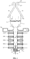
- FIG.1 shows a cross sectional view of a typical blown film extrusion process employing a short stack cooling system with divergent cooling elements of the present invention.
- all thin arrows indicating a direction are for illustrative purposes only, labeled for example as AF, and indicate a direction flow of a fluid (e.g. cooling gas).
- Thick arrows indicating a direction are for illustrative purposes only, labeled for example as MF, and indicate a direction flow of a plastic film material (e.g. molten film tube).
- Thermoplastic resin is introduced through feed hopper 2 into extruder 4 where the resin is melted, mixed and pressurized. Molten resin is conveyed through melt pipe 6 into a die means 8 that forms it into an annular molten flow that exits generally from the top surface of die means 8 as a molten film tube 12.
- Internal gas supply conduit 10 operably provides an internal cooling/inflating gas through die means 8 to the interior of molten film tube 12 and solidified film tube 16.
- Internal gas exhaust conduit 9 operably removes internal cooling/inflating gas through die means 8 as required to maintain a desired trapped tube volume of gas inside molten film tube 12 and solidified film tube 16, further contained by nip rollers 20.
- Gas flow through Internal gas supply conduit 10 and Internal gas exhaust conduit 9 are controlled by methods commonly understood by those skilled in the art.
- Molten film tube 12 expands outwardly around the trapped tube volume of gas and is drawn upwardly by nip rollers 20 while being cooled to solidify at freeze line 14 forming solidified film tube 16.
- Solidified film tube 16 is collapsed by flattening guides 18 before passing through nip rollers 20 forming flattened film 22. Flattened film 22 is then conveyed to downstream equipment for conversion into usable products as desired.
- Annular cooling elements 23, 24a-d, and 26 are arranged coaxial with and in the direction of flow of molten film tube 12. Cooling elements 23, 24a-d, and 26, each supplied with cooling gas from a suitable external source, direct associated cooling gas alongside molten film tube 12, generally in the same and/or opposite direction to the flow of molten film tube 12, acting to stabilize and cool molten film tube 12.
- Upward cooling gas traveling generally in the direction of flow of molten film tube 12 from cooling elements 23 and 24a-c, and downward cooling gas traveling generally opposite the direction of flow of molten film tube 12 from cooling elements 24a-d flows alongside and cools molten film tube 12, and exhausts between cooling elements 23 and 24a-d to the surrounding atmosphere.
- Generally upwardly directed cooling gas from cooling element 26 flows unrestricted, along molten film tube 12, directly influenced by the surrounding atmosphere, while cooling and allowing for free expansion of molten film tube 12.
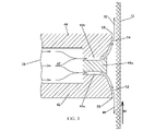
- FIG. 2 shows a cross sectional view of the inner portion of one half of a divergent cooling element, of the present invention.
- Each divergent cooling element ( FIG. 1 , 24a-d) is provided with an interior air plenum 38 of any suitable shape and size, that directs the associated supplied cooling gas to flow generally radially inward through annular channel 40 formed between cooling members 42 and 44.
- Annular channel 40 feeds cooling gas toward cooling gas deflector 46, inwardly supported from cooling members 42 and/or 44 using common, readily available fastening means such as screws and washers, not shown. Cooling gas deflector 46 prevents direct cooling gas flow against molten film tube 12 and separates cooling gas flow into oppositely directed cooling gas streams 48 and 50.
- Cooling gas stream 48 flows generally opposite the direction of the flow of molten film tube 12, between air foil surface 52 and molten film tube 12. Cooling gas stream 50 flows generally in the same direction of flow of molten film tube 12, between air foil surface 54 and molten film tube 12.
- Air foil surfaces 52 and 54 are annularly angled inward toward molten film tube 12, in the direction of respective air flow just prior to terminating at air foil exit tips 56 and 58, where cooling gas streams 48 and 50 leave the influence of air foil surfaces 52 and 54 respectively and flow in cooling contact along the surface of molten film tube 12. Compound angles are preferentially employed along air foil surfaces 52 and 54 with larger angles relative to molten film tube 12 located nearest to cooling gas deflector 46, and smaller angles located adjacent respective air foil exit tips 56 and 58.
- no portion of the divergent cooling element having a divergent cooling interface comprised of cooling gas deflector 46, air foil surfaces 52 and 54, and air foil exit tips 56 and 58 is closer to the molten film tube than either one or both of the air foil exit tips 56 and 58, to ensure that no mechanical contact with molten film tube 12 can occur.
- cooling gas deflector 46 is replaced by cooling gas deflector 46a located intermediate cooling members 42 and 44, forming a pair of annular channels 40a and 40b.
- Cooling gas from interior air plenum 38 generally flows radially inward, independently through annular channels 40a and 40b, exiting the influence of cooling gas deflector 46a as oppositely directed cooling gas streams 48 and 50, respectively.
- Cooling gas stream 48 flows generally opposite the direction of flow of molten film tube 12, between air foil surface 52 and molten film tube 12.
- Cooling gas stream 50 flows generally in the same direction of flow of molten film tube 12, between air foil surface 54 and molten film tube 12.
- air foil surfaces 52 and 54 are annularly angled inward toward molten film tube 12, in the direction of respective air flow just prior to terminating at air foil exit tips 56 and 58, where cooling gas streams 48 and 50 leave the influence of air foil surfaces 52 and 54 respectively and flow in cooling contact along the surface of molten film tube 12.
- Compound angles are preferentially employed along air foil surfaces 52 and 54 with larger angles relative to molten film tube 12 located nearest to cooling gas deflector 46a, and smaller angles located adjacent respective air foil exit tips 56 and 58.
- no portion of the divergent cooling element having a divergent cooling interface comprised of cooling gas deflector 46a, air foil surfaces 52 and 54, and air foil exit tips 56 and 58 is closer to the molten film tube than either one or both of the air foil exit tips 56 and 58, to ensure that no mechanical contact with molten film tube 12 can occur.
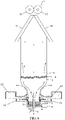
- FIG.4 depicts a cooling system employing high performance, divergent cooling elements of the present invention in a configuration similar to FIG. 1 , but with the addition of a enclosure 28, variable exhaust device 30, variable controller means 32, and flow buffer 34 with freely swinging flapper 36 as described in co-pending application titled Controlled Pressure Enclosure filed on January 15, 2016 with first named inventor Robert E. Cree, filed under attorney docket number 100646.000004, the contents of which is hereby incorporated by reference.
- Cooling gas supply conduits 60 are also added, spaced generally inside and around the perimeter of cooling elements 23, 24a, 24b and 24c, forming a common supply of cooling gas.
- Cooling gas supply conduits 60 also act to space apart and locate concentric to molten film tube 12 each of the associated cooling elements 23, 24a, 24b and 24c. Cooling element 24d is advantageously shown supplied with cooling gas in common with cooling element 26, forming a high performance triple flow air ring. Cooling element 26 is depicted with one single-flow of cooling gas, but can include more than one flow of cooling gas, forming further high performance multiple-flow versions in combination with cooling element 24d of the present invention, exiting to flow unrestricted, generally upward and along molten film tube 12, directly influenced by the surrounding atmosphere, while cooling and allowing for free expansion of molten film tube 12. Cooling element 26 may also be omitted, allowing cooling gas exiting from the upper most located high performance, divergent cooling element to either be located below frost line 14 and allow for free expansion or be located above frost line 14 and constrain the molten film tube 12.
- the present invention is presented on an upward blown film extrusion process, but equally applies to horizontal or downward versions of the blown film extrusion process, without limit. Further, the present invention can be employed in a linear rather than annular configuration, and applies to collapsing frame stabilization as well as single sheet cast film prior art.
- Block 502 presents receiving, by at least one divergent cooling element, a flow of a molten film tube; and cooling, by the at least one divergent cooling element, the flow of the molten film tube, wherein the at least one divergent cooling element comprises a divergent cooling interface operable for expelling a cooling gas (i) in a path opposing the flow of the molten film tube toward a first exit gap and (ii) in a path with the flow of the molten film tube toward a second exit gap, wherein at least one of the first exit gap and the second exit gap define a minimum gap between the divergent cooling interface and the flow of the molten film tube.
- Block 504 relates to wherein the at least one divergent cooling interface comprises a cooling gas deflector for directing expelled cooling gas along the path opposing the flow of the molten film tube and along the path with the flow of the mol
- block 506 indicates further comprising cooling by a second cooling element stacked adjacent the at least one divergent cooling element.
- Block 508 specifies further comprising cooling the flow of the molten film tube by at least one of a triple flow air ring and a multiple flow air ring.
- Block 510 indicates wherein a space is defined between the at least one divergent cooling element and the second cooling element to allow gas exchange with a surrounding atmosphere.
- Block 512 then states wherein a portion of the divergent cooling interface expelling the cooling gas in the path opposing the flow of the molten film tube forms compound angles, and wherein a portion of the divergent cooling interface expelling the cooling gas in the path with the flow of the molten film forms compound angles.
- Block 514 relates to wherein the expelled cooling gas from the at least one divergent cooling element sufficiently cools the molten film tube at a rate between 8.9 and 89 (kg/hour)/(meter of die circumference) (0.5 and 5 (pounds/hour)/(inch of die circumference)).
- block 516 then states wherein at least a portion of the cooling gas is received by at least one enclosure comprising a cavity for receiving the cooling gas from the at least one divergent cooling element, the at least one enclosure operable to maintain a predetermined pressure differential between an inside surface and an outside surface of the flow of the molten film tube.
- the logic flow diagram may be considered to illustrate the operation of a method.
- the logic flow diagram may also be considered a specific manner in which components of a device are configured to cause that device to operate, whether such a device is a blown film tubular extrusion device, controlled pressure enclosure, or divergent cooling element, or one or more components thereof.
- FIG. 6 shown is a cross sectional view of a typical blown film extrusion process employing a cooling system, which is not claimed but is useful for understanding the invention, especially the embodiment of figure 9 , the cooling system of FIG. 6 employing an annular cooling element 23 (also known as a unidirectional cooling element), arranged coaxial with and in the direction of flow of molten film tube 12 adjacent the top surface of die means 8.
- Cooling element 26 is arranged coaxial with and in the direction of flow of molten film tube 12 adjacent the top surface of cooling element 23.
- Cooling elements 23 and 26 are shown with connecting passages 62 that allow for a common supply of cooling gas from a suitable external source, however, cooling elements 23 and 26 can also be independently supplied with cooling gas from an external source. Cooling elements 23 and 26, direct cooling gas alongside molten film tube 12, generally in the same direction as the flow of molten film tube 12, stabilizing and cooling molten film tube 12.
- FIG. 7 shows a close-up cross sectional view of the inner portion of one half of a unidirectional cooling element operable to expel cooling gas.
- cooling elements 23 and 26 are shown having independent cooling gas supplies from a suitable external source, however, it should be appreciated that embodiments of cooling elements 23 and 26 can be supplied from a common supply of cooling gas (shown in FIG. 6 ).
- cooling element 26 is stacked on top of cooling element 23 such that cooling element 26 is in contact with cooling element 23 thereby substantially preventing gas exchange with the surrounding atmosphere between cooling element 26 and cooling element 23.
- Cooling element 23 is provided with an interior air plenum 38u of any suitable shape and size, that directs the associated supplied cooling gas to flow generally radially inward through annular channel 40u formed between cooling members 42u and 44u.
- Annular channel 40u feeds cooling gas toward cooling gas deflector 46u, formed as an extension of cooling member 42u. Cooling gas deflector 46u prevents direct cooling gas flow against molten film tube 12 and directs cooling gas stream 50u to flow generally in the same direction of flow of molten film tube 12, between air foil surface 54u and molten film tube 12.
- Cooling gas deflector 46u as depicted, is rectangular shaped, however, it should be appreciated that embodiments of cooling gas deflector 46u includes any shape (e.g., triangular or curved) that operably redirects cooling gas toward air foil surface 54u in the path of the flow of molten film tube 12.
- Air foil surface 54u is annularly angled inward toward molten film tube 12, in the direction of cooling gas flow just prior to terminating at air foil exit tip 58u, where the cooling gas stream 50u leaves the influence of air foil surface 54u and continues to flow in cooling contact along the surface of molten film tube 12. As shown in FIG. 7 , compound angles are employed along air foil surface 54u with larger angles relative to molten film tube 12 located nearest to cooling gas deflector 46u, and smaller angles located adjacent respective air foil exit tip 58u.
- air foil surface 54u need not include compound angles, but can include an angled or curved surface relative to molten film tube 12 provided that a minimum gap between air foil surface 54u and the surface of molten film tube 12 is located at air foil exit tip 58u. No portion of cooling element 23 having a unidirectional cooling interface comprised of cooling gas deflector 46u, air foil surface 54u, and air foil exit tip 58u is closer to the molten film tube than air foil exit tip 58u.
- cooling gas deflector 46u radially spaced outwardly from the exit point of die means 8, where the annular molten flow exiting die means 8 forms molten film tube 12.
- Cooling element 26 is a single flow air ring that directs cooling gas toward the outside surface of molten film tube 12 in the path of the flow of molten film tube 12.
- the molten film tube 12 is extruded from die means 8 (e.g., a spiral distribution extrusion die), and received by unidirectional cooling element 23.
- Unidirectional cooling element 23 expels cooling gas deflected by cooling gas deflector 46u in the path of the flow of the molten film tube 12.
- the cooling gas exiting from the influence of cooling gas deflector 46u, and flowing between air foil surface 54u and molten film tube 12 flows towards air foil exit tip 58u where the cooling gas exits from cooling element 23 towards cooling element 26.
- Cooling element 26 receives the expelled cooling gas from cooling element 23 at its cooling interface 64, and also expels cooling gas in the path of the flow of the molten film tube 12 from annular channel 66.
- FIG. 7 depicts cooling element 26 with a cooling interface 64 in the shape and form of a dual flow air ring with the first annular gap removed and replaced by cooling element 23. It should be appreciated that cooling element 26 can be any suitable shape and form, including employing more than one flow of cooling gas, as long as cooling element 23 is arranged to receive the flow of molten film tube 12 prior to cooling element 26.
- Cooling elements 23 and 26 direct associated cooling gas circumferentially along the outside surface of molten film tube 12, generally in the same direction to the flow of molten film tube 12, acting to stabilize and cool molten film tube 12.
- Molten film tube 12 is cooled by the cooling gas expelled from cooling elements 23 and 26 such that at some given distance above cooling element 26, molten film tube 12 solidifies at freeze line 14 forming solidified film tube 16.
- Embodiments of cooling elements 23 and 26 expel cooling gas and create a vacuum between molten film tube 12 and their cooling interface such that molten film tube 12 is pulled or urged radially outward toward the cooling elements interface.
- Embodiments of cooling element 23 provide a means to cool molten film tube 12 such that molten film tube 12 is cooled at a rate between 8.9 and 89 (kg/hour)/(meter of die circumference) (0.5 and 5 (pounds/hour)/(inch of die circumference)) in addition to the cooling rate of cooling element 26.
- Embodiments of cooling elements 23 and 26 are operable to expel cooling gas at a rate between 2,000 to 20,000 feet/minute.
- Embodiments of the cooling element 23 provide a cooling interface wherein the expelled cooling gas is expelled such that during operation the cooling interface is covered or lubricated by expelled cooling gas.
- cooling interface of cooling element 23 provides an air foil exit tip 58u that is the closest portion of cooling element 23 to the surface of molten film tube 12, with expelled cooling gas flowing between the air foil exit tip 58u and molten film tube 12 and no portion of cooling element 23 is in direct contact with molten film tube 12.
- Block 802 provides (a) receiving, by a unidirectional cooling element, a flow of a molten film tube; and (b) cooling, by the unidirectional cooling element, the flow of molten film tube, wherein the unidirectional cooling element comprises a unidirectional cooling interface operable for expelling a cooling gas in a path with the flow of the molten film tube toward an exit gap, wherein the exit gap defines a minimum gap with expelled cooling gas flowing between the unidirectional cooling interface and the blow of the molten film tube.
- the unidirectional cooling interface comprises a cooling gas deflector for directing expelled cooling gas along the path with the flow of the molten film tube.
- block 806 specifies the method further comprising cooling by a second cooling element stacked adjacent the unidirectional cooling element.
- Block 808 relates to the method further comprising cooling the flow of the molten film tube by at least one of a single flow air ring, a dual flow air ring, a triple flow air ring, and a multiple flow air ring.
- Block 810 specifies the method further comprising cooling the flow of the molten film tube by the second cooling element comprising a single flow air foil having a cooling interface operable to expel cooling gas in the path with the flow of the molten film tube, and receive expelled cooling gas from the unidirectional cooling element along the cooling interface.
- Block 812 states wherein the single flow air flow foil is a dual flow air foil with a first annular gap removed.
- Block 814 then states wherein a portion of the unidirectional cooling interface expelling the cooling gas in the path with the flow of the molten film form compound angles.
- block 816 indicates wherein the expelled cooling gas from the unidirectional cooling element sufficiently cools the molten film tube at a rate between 8.9 and 89 (kg/hour)/(meter of die circumference) (0.5 and 5 (pounds/hour)/(inch of die circumference)).
- block 818 states wherein the unidirectional cooling element is operable to expel cooling gas at a rate of between 2,000 to 20,000 feet/minute.
- the logic flow diagram shown in FIG. 8 may be considered to illustrate the operation of a method.
- the logic flow diagram may also be considered a specific manner in which components of a device are configured to cause that device to operate, whether such a device is a blown film tubular extrusion device, controlled pressure enclosure, or unidirectional cooling element, or one or more components thereof.
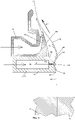
- FIG. 9 depicts a cooling system employing a high performance, divergent cooling element of the present invention in a configuration similar to FIG. 7 , but with cooling element 23 replaced by cooling element 24d operating as a divergent cooling element as described in FIG. 2 and 3 .
- Cooling element 26 is depicted with one single-flow of cooling gas, but can include more than one flow of cooling gas, forming further high performance multiple-flow versions in combination with cooling element 24d of the present invention, exiting to flow unrestricted, generally upward and along molten film tube 12, directly influenced by the surrounding atmosphere, while cooling and allowing for free expansion of molten film tube 12.
- Cooling element 24d and cooling element 26 as depicted form a high performance triple flow air ring, spaced apart from and coaxial with die means 8, in the direction of flow of molten film tube 12, and provide enhanced stability and output rate.
- the spaced apart distance between cooling element 24d and die means 8, can be fixed or adjustable, acting to cool and support the molten film tube 12 at locations from just above die means 8 up to several feet above die means 8.
Landscapes
- Engineering & Computer Science (AREA)
- Mechanical Engineering (AREA)
- Physics & Mathematics (AREA)
- Thermal Sciences (AREA)
- Manufacturing & Machinery (AREA)
- Extrusion Moulding Of Plastics Or The Like (AREA)
- Shaping By String And By Release Of Stress In Plastics And The Like (AREA)
- Crystals, And After-Treatments Of Crystals (AREA)
- Chemical Vapour Deposition (AREA)
Description
- The present disclosure relates to an apparatus for cooling. The present disclosure relates more particularly to a method and apparatus for high performance cooling.
- Various methods to manufacture thermoplastic blown films are well known in the plastics art, and typically involve forming a continuous, vertically oriented, seamless, annular plastic film commonly referred to as the "tube" or "bubble". Thermoplastic material is melted and pumped by an extruder through a blown film die (die), exiting as an annular flow of a molten film, continuously drawn upward by a pair of driven squeeze rollers. Gas is typically manually injected through the die to the interior of the exiting annular flow of molten film. The driven squeeze rollers act to prevent gas from escaping, trapping the injected gas inside, forming a molten film tube which is inflated by the injected gas until at the desired size and the die is sealed off to prevent inflation gas from escaping. The molten film tube is pulled upward by the driven squeeze rollers, flowing generally upward from the die through a cooling system, where it stretches, expands, and cools around the now trapped column of injected gas until it solidifies at a frost line into a solidified film tube. The solidified film tube passes through various stabilizers and enters a flattening device, which converts the tube into a flattened double thickness thermoplastic sheet of film known as "lay-flat". The lay-flat passes through the driven squeeze rollers, and is conveyed to downstream converting equipment such as winders and bag making machines for further processing.
- To remain competitive, manufacturers of blown film must maximize throughput rate and quality, however cooling system performance is a significant limiting factor. The weight of thermoplastic that is extruded per unit time divided by the circumference of the die exit, provides a commonly used measure of throughput performance, and is expressed in units of PPH/lnch, Pounds Per Hour per Inch of die exit circumference. Many different cooling systems have been developed and employed, both external and internal to the tube, and to varying degrees these systems have achieved commercial success.
- Blown film cooling systems provide a flow of cooling gas typically external, but in many cases also internal to the molten film tube. Cooling systems are designed using well known Bernoulli and Coandprinciples, and in many cases, apply the cooling gas to flow generally along the surface of the molten film tube to create holding forces on the molten film tube, providing for both stability and cooling of the molten film tube. Excessive holding forces, if present, can cause vibration, flutter, and high noise levels in the process, and can pull the molten film tube into undesirable contact with the cooling element, creating drag and causing marks and instability in the molten film tube. In other cases, cooling gas is instead applied generally against the surface of the molten film tube, typically creating turbulent cooling with repelling forces, requiring a separate means to stabilize the molten film tube.

- External cooling systems, generally provide the primary means for stabilization and cooling of the molten film tube, are generally easy to operate and used on most blown film extrusion processes. External cooling systems provide a flow of cooling gas along the outside surface of the molten film tube that typically generates holding forces while cooling the molten film tube, until the cooling gas dissipates into the surrounding atmosphere. Less typically, cooling gas is aimed generally inward generating repelling forces while cooling the molten film tube, undesirably requiring a separate means to hold and stabilize the molten film tube.
- Present art external cooling systems are made up of various types of cooling elements. The earliest cooling element, known as a "Single Flow air ring", still in common use today, applies a single flow of cooling gas around the molten film tube. Single Flow cooling elements typically produce good film quality, but at lower throughput rates. Additional flows of cooling gas have been added to cooling elements over time to create various multiple flow designs, such as "Dual Flow", "Triple Flow" or "Quad Flow" designs, and some external cooling systems pair cooling elements into various configurations, depending on the application, to form what is generically known as a "Tandem" air ring. External cooling systems are typically fixed in place, but can be made adjustable in height above the die to allow extending the cooled surface area along the molten film tube, producing higher throughput, but also resulting in greater unsupported surface area between the cooling element and die, which is the hottest and weakest portion of the molten film tube, which can lead to degraded stability, making it more difficult to operate and potentially leading to a narrower range of film sizes.
- In contrast, internal cooling systems typically do not provide primary stabilization, and are selectively used typically to generate additional throughput beyond the capability of an external cooling system. Internal cooling systems replace manual gas injection and inflate the molten film tube with a flow of an internal supply gas that enters through the die. Although some recent high throughput internal cooling systems apply cooling gas to create holding forces, more typically cooling gas is directed against the inside surface of the molten film tube, acting to generally repel and cool the inside surface of the molten film tube. The flow of internal supply gas is trapped inside the bubble and cannot dissipate into the atmosphere, therefore complex control systems are used to balance a flow of internal exhaust gas that exits through the die to maintain a constant bubble size as is well known and understood by those skilled in the art. Internal cooling systems can be difficult or even impossible to use depending on such factors as operator skill, thermoplastic material properties, and the physical size and design of the associated die.
- It is highly desired to overcome the drawbacks of prior art thermoplastic cooling systems and provide a cooling system that significantly increases throughput rate, maximizes aerodynamic holding forces, allows relatively large unsupported regions of the molten tube with good stability, produces a wide range of film sizes, prevents drag on the molten film surface, minimizes turbulence, vibration and flutter, does not produce high sound power levels, and is simple and easy to control.
-
US4330501 discloses a method and apparatus for cooling film bubble of low strain hardening polymers.FR2517248 US4259047 discloses an air ring for the production of blown film.US4728277 discloses the preamble of claim 1 or a film-handling device for thin flexible films. - In view of the foregoing, it is an object of the present disclosure to provide an apparatus for cooling.
- The present invention provides an apparatus for cooling according to the claims.
- The present disclosure presents an apparatus for cooling according to claim 1. The apparatus includes at least one divergent cooling element for receiving a flow of a molten film tube, the at least one divergent cooling element including a divergent cooling interface operable for expelling a cooling gas (i) in a path opposing the flow of the molten film tube toward a first exit gap and (ii) in a path with the flow of the molten film tube toward a second exit gap, wherein at least one of the first exit gap and the second exit gap define a minimum gap between the divergent cooling interface and the flow of the molten film tube.
- The divergent cooling interface includes a cooling gas deflector for directing expelled cooling gas along the path opposing the flow of the molten film tube and along the path with the flow of the molten film tube.
- An exemplary embodiment includes wherein a portion of the divergent cooling interface in the path opposing the flow of the molten film tube forms one or more compound angles, and wherein a portion of the divergent cooling interface in the path with the flow of the molten film forms one or more compound angles.
- The present disclosure presents a method for cooling, which is not claimed. The method includes receiving, by at least one divergent cooling element, a flow of a molten film tube. The method further includes cooling, by the at least one divergent cooling element, the flow of the molten film tube, wherein the at least one divergent cooling element comprises a divergent cooling interface operable for expelling a cooling gas (i) in a path opposing the flow of the molten film tube toward a first exit gap and (ii) in a path with the flow of the molten film tube toward a second exit gap, wherein at least one of the first exit gap and the second exit gap define a minimum gap between the divergent cooling interface and the flow of the molten film tube.
- The following will describe embodiments of the present invention, but it should be appreciated that the present invention is not limited to the described embodiments and various modifications of the invention are possible without departing from the basic principles. The scope of the present disclosure is therefore to be determined solely by the appended claims.
-
-
FIG. 1 is a cross sectional view of a device suitable for use in practicing exemplary embodiments of this disclosure. -
FIG. 2 is a close-up cross sectional view of an exemplary cooling element suitable for use in practicing exemplary embodiments of this disclosure. -
FIG. 3 is a close-up cross sectional view of an alternative exemplary cooling element suitable for use in practicing exemplary embodiments of this disclosure. -
FIG. 4 is a cross sectional view of an alternative device suitable for use in practicing exemplary embodiments of this disclosure. -
FIG. 5 is a logic flow diagram in accordance with a method and apparatus for performing exemplary embodiments of this disclosure. -
FIG. 6 is a cross sectional view of an alternative device, which is not claimed and is suitable for use in practicing exemplary embodiments of this disclosure. -
FIG. 7 is a close-up cross sectional view of an alternative exemplary cooling element not claimed and suitable for use in practicing exemplary embodiments of this disclosure. -
FIG. 8 is a logic flow diagram in accordance with a method and apparatus which are not claimed and are suitable for performing exemplary embodiments of this disclosure. -
FIG. 9 is a close-up cross sectional view of an alternative exemplary cooling element suitable for use in practicing exemplary embodiments of this disclosure. - Exemplary embodiments of the present disclosure relate to a high performance cooling system for the blown film tubular extrusion process providing increased throughput rate at high quality. Embodiments of the high performance cooling system include one or more cooling elements, capable of being stacked to achieve higher throughput, wherein at least one of the one or more cooling elements is a divergent cooling element incorporating a cooling gas deflector and a pair of opposed cooling members having respective opposed air foil surfaces (surfaces). The surfaces and cooling gas deflector form a divergent cooling interface that directs cooling gas to flow in opposite directions, creating suction forces. These suction forces stabilize and hold the molten film tube (melt) in cooling proximity with the divergent cooling element. Oppositely directed cooling gas flows are expelled between the divergent cooling interface and the melt (i) in a path opposing the flow of the molten film tube along a first surface toward a first air foil exit tip to form a first exit gap with the melt and (ii) in a path with the flow of the molten film tube along a second surface toward a second air foil exit tip to form a second exit gap with the melt.
- The divergent cooling interface includes air foil exit tips that are angled inward toward the surface of the molten film tube, and extend closer to the molten film tube than any other portion of the divergent cooling element. All portions of the divergent cooling interface are recessed within the air foil exit tips away from the molten film tube, preventing hang-up inducing drag. The angled in air foil exit tips act to compress the cooling gas stream, providing a cushioning effect that dampen vibrations and flutter in the molten film tube, and eliminate excessive sound power levels. Additionally, the angled in airfoil exit tips act similar to a venturi, to accelerate the cooling gas streams flowing along the molten film tube to a higher velocity where the cooling gas streams emerge from the influence of associated cooling members at the air foil exit tips and flow along the molten film tube. This higher velocity cooling gas flow translates into higher cooling efficiency and throughput.
- Further, one or more compound angles are preferentially employed along the air foil surfaces. Larger surface angles (up to about 45 degrees from parallel to the molten film surface) provide greater compression of the cooling gas, which desirably improves cooling efficiency, but unfortunately, also can cause an undesirable reduction in holding force. Use of compound angles wraps the cooling gas flow smoothly around cooling element air foil surfaces, which are advantageously arranged to change from a larger to a smaller angle relative to the molten film tube, in the direction of cooling gas flow, prior reaching the air foil exit tips. This approach allows larger initial cooling member air foil surface angles which act to aggressively compress the cooling gas streams for maximum cooling efficiency, followed by smaller surface angles, just prior and up to the air foil exit tips, which act to accelerate the cooling gas streams, restoring holding force to a maximum. Divergent cooling elements with compound angles in the cooling member air flow surfaces, exhibit very high cooling efficiency, maximum holding force, and excellent stability, without vibration, flutter or high sound power levels.
- Advantageously, a simplified single air delivery channel is provided between first and second cooling members, feeding an inward radial flow of cooling gas arranged to impinge on an outer wall of a cooling gas deflector, preventing direct cooling gas flow against the blown film tube and separating the flow into oppositely directed first and second annular cooling gas streams. The cooling gas deflector generally arranged intermediate between the cooling members and the molten tube such that the inner wall of the cooling gas deflector is spaced further from the molten tube than the associated cooling member tips to prevent drag. Additional flows of cooling gas can be advantageously added, but are not required.
- Embodiments of a divergent flow, high performance cooling element of the present invention include a simplified air delivery channel feeding one or more compound angle cooling member air foil surface with an initial 22.5 degree angle followed by a 7.5 degree air foil exit tip angle, provide an increased holding force, reduced vibration and flutter resulting in measured sound power levers 18 db lower (64 times less) than divergent cooling elements with a 0 degree air foil exit tip angle. Embodiments of the present disclosure include one or more compound angle cooling member air foil surface with an initial angle between 15 and 25 degrees, followed by an exit tip angle between 5 and 15 degrees with excellent stability, efficiency gains, increased holding force, reduced vibration and flutter. However, it should be appreciated that embodiments include a cooling gas foil surface and an exit tip angle with any combination of compound angles that aid in increasing throughput, stability, and in reducing vibration and flutter.
-
FIG.1 shows a cross sectional view of a typical blown film extrusion process employing a short stack cooling system with divergent cooling elements of the present invention. InFIG. 1 - FIG. 4 , andFIGs. 6-7 , all thin arrows indicating a direction are for illustrative purposes only, labeled for example as AF, and indicate a direction flow of a fluid (e.g. cooling gas). Further, Thick arrows indicating a direction are for illustrative purposes only, labeled for example as MF, and indicate a direction flow of a plastic film material (e.g. molten film tube). Thermoplastic resin is introduced throughfeed hopper 2 intoextruder 4 where the resin is melted, mixed and pressurized. Molten resin is conveyed throughmelt pipe 6 into a die means 8 that forms it into an annular molten flow that exits generally from the top surface of die means 8 as amolten film tube 12. - Internal
gas supply conduit 10 operably provides an internal cooling/inflating gas through die means 8 to the interior ofmolten film tube 12 and solidifiedfilm tube 16. Internalgas exhaust conduit 9 operably removes internal cooling/inflating gas through die means 8 as required to maintain a desired trapped tube volume of gas insidemolten film tube 12 and solidifiedfilm tube 16, further contained by niprollers 20. Gas flow through Internalgas supply conduit 10 and Internalgas exhaust conduit 9 are controlled by methods commonly understood by those skilled in the art.Molten film tube 12 expands outwardly around the trapped tube volume of gas and is drawn upwardly by niprollers 20 while being cooled to solidify atfreeze line 14 forming solidifiedfilm tube 16. Solidifiedfilm tube 16 is collapsed by flatteningguides 18 before passing through niprollers 20 forming flattenedfilm 22. Flattenedfilm 22 is then conveyed to downstream equipment for conversion into usable products as desired. -
Annular cooling elements molten film tube 12. Coolingelements molten film tube 12, generally in the same and/or opposite direction to the flow ofmolten film tube 12, acting to stabilize and coolmolten film tube 12. - Upward cooling gas traveling generally in the direction of flow of
molten film tube 12 from coolingelements molten film tube 12 from coolingelements 24a-d flows alongside and coolsmolten film tube 12, and exhausts betweencooling elements element 26 flows unrestricted, alongmolten film tube 12, directly influenced by the surrounding atmosphere, while cooling and allowing for free expansion ofmolten film tube 12. -
FIG. 2 shows a cross sectional view of the inner portion of one half of a divergent cooling element, of the present invention. Each divergent cooling element (FIG. 1 , 24a-d) is provided with aninterior air plenum 38 of any suitable shape and size, that directs the associated supplied cooling gas to flow generally radially inward throughannular channel 40 formed between coolingmembers Annular channel 40 feeds cooling gas toward coolinggas deflector 46, inwardly supported from coolingmembers 42 and/or 44 using common, readily available fastening means such as screws and washers, not shown. Coolinggas deflector 46 prevents direct cooling gas flow againstmolten film tube 12 and separates cooling gas flow into oppositely directed cooling gas streams 48 and 50. Coolinggas stream 48 flows generally opposite the direction of the flow ofmolten film tube 12, betweenair foil surface 52 andmolten film tube 12. Coolinggas stream 50 flows generally in the same direction of flow ofmolten film tube 12, betweenair foil surface 54 andmolten film tube 12. - Air foil surfaces 52 and 54 are annularly angled inward toward
molten film tube 12, in the direction of respective air flow just prior to terminating at airfoil exit tips molten film tube 12. Compound angles are preferentially employed along air foil surfaces 52 and 54 with larger angles relative tomolten film tube 12 located nearest to coolinggas deflector 46, and smaller angles located adjacent respective airfoil exit tips gas deflector 46, air foil surfaces 52 and 54, and airfoil exit tips foil exit tips molten film tube 12 can occur. - In
FIG. 3 , coolinggas deflector 46 is replaced by coolinggas deflector 46a locatedintermediate cooling members annular channels interior air plenum 38 generally flows radially inward, independently throughannular channels gas deflector 46a as oppositely directed cooling gas streams 48 and 50, respectively. Coolinggas stream 48 flows generally opposite the direction of flow ofmolten film tube 12, betweenair foil surface 52 andmolten film tube 12. Coolinggas stream 50 flows generally in the same direction of flow ofmolten film tube 12, betweenair foil surface 54 andmolten film tube 12. - As described in
FIG. 2 , air foil surfaces 52 and 54 are annularly angled inward towardmolten film tube 12, in the direction of respective air flow just prior to terminating at airfoil exit tips molten film tube 12. Compound angles are preferentially employed along air foil surfaces 52 and 54 with larger angles relative tomolten film tube 12 located nearest to coolinggas deflector 46a, and smaller angles located adjacent respective airfoil exit tips gas deflector 46a, air foil surfaces 52 and 54, and airfoil exit tips foil exit tips molten film tube 12 can occur. -
FIG.4 depicts a cooling system employing high performance, divergent cooling elements of the present invention in a configuration similar toFIG. 1 , but with the addition of aenclosure 28,variable exhaust device 30, variable controller means 32, and flowbuffer 34 with freely swingingflapper 36 as described in co-pending application titled Controlled Pressure Enclosure filed on January 15, 2016 with first named inventor Robert E. Cree, filed under attorney docket number 100646.000004, the contents of which is hereby incorporated by reference. Coolinggas supply conduits 60 are also added, spaced generally inside and around the perimeter of coolingelements gas supply conduits 60 also act to space apart and locate concentric tomolten film tube 12 each of the associatedcooling elements Cooling element 24d is advantageously shown supplied with cooling gas in common withcooling element 26, forming a high performance triple flow air ring. Coolingelement 26 is depicted with one single-flow of cooling gas, but can include more than one flow of cooling gas, forming further high performance multiple-flow versions in combination withcooling element 24d of the present invention, exiting to flow unrestricted, generally upward and alongmolten film tube 12, directly influenced by the surrounding atmosphere, while cooling and allowing for free expansion ofmolten film tube 12. Coolingelement 26 may also be omitted, allowing cooling gas exiting from the upper most located high performance, divergent cooling element to either be located belowfrost line 14 and allow for free expansion or be located abovefrost line 14 and constrain themolten film tube 12. - The present invention is presented on an upward blown film extrusion process, but equally applies to horizontal or downward versions of the blown film extrusion process, without limit. Further, the present invention can be employed in a linear rather than annular configuration, and applies to collapsing frame stabilization as well as single sheet cast film prior art.
- Referring to
FIG. 5 , presented is an exemplary logic flow diagram in accordance with a method and apparatus for performing exemplary embodiments of this disclosure.Block 502 presents receiving, by at least one divergent cooling element, a flow of a molten film tube; and cooling, by the at least one divergent cooling element, the flow of the molten film tube, wherein the at least one divergent cooling element comprises a divergent cooling interface operable for expelling a cooling gas (i) in a path opposing the flow of the molten film tube toward a first exit gap and (ii) in a path with the flow of the molten film tube toward a second exit gap, wherein at least one of the first exit gap and the second exit gap define a minimum gap between the divergent cooling interface and the flow of the molten film tube.Block 504 relates to wherein the at least one divergent cooling interface comprises a cooling gas deflector for directing expelled cooling gas along the path opposing the flow of the molten film tube and along the path with the flow of the molten film tube. - Then block 506 indicates further comprising cooling by a second cooling element stacked adjacent the at least one divergent cooling element.
Block 508 specifies further comprising cooling the flow of the molten film tube by at least one of a triple flow air ring and a multiple flow air ring.Block 510 then indicates wherein a space is defined between the at least one divergent cooling element and the second cooling element to allow gas exchange with a surrounding atmosphere.Block 512 then states wherein a portion of the divergent cooling interface expelling the cooling gas in the path opposing the flow of the molten film tube forms compound angles, and wherein a portion of the divergent cooling interface expelling the cooling gas in the path with the flow of the molten film forms compound angles. -
Block 514 relates to wherein the expelled cooling gas from the at least one divergent cooling element sufficiently cools the molten film tube at a rate between 8.9 and 89 (kg/hour)/(meter of die circumference) (0.5 and 5 (pounds/hour)/(inch of die circumference)). Finally block 516 then states wherein at least a portion of the cooling gas is received by at least one enclosure comprising a cavity for receiving the cooling gas from the at least one divergent cooling element, the at least one enclosure operable to maintain a predetermined pressure differential between an inside surface and an outside surface of the flow of the molten film tube. - The logic flow diagram may be considered to illustrate the operation of a method. The logic flow diagram may also be considered a specific manner in which components of a device are configured to cause that device to operate, whether such a device is a blown film tubular extrusion device, controlled pressure enclosure, or divergent cooling element, or one or more components thereof.
- Referring to
FIG. 6 , shown is a cross sectional view of a typical blown film extrusion process employing a cooling system, which is not claimed but is useful for understanding the invention, especially the embodiment offigure 9 , the cooling system ofFIG. 6 employing an annular cooling element 23 (also known as a unidirectional cooling element), arranged coaxial with and in the direction of flow ofmolten film tube 12 adjacent the top surface of die means 8. Coolingelement 26 is arranged coaxial with and in the direction of flow ofmolten film tube 12 adjacent the top surface of coolingelement 23. Coolingelements passages 62 that allow for a common supply of cooling gas from a suitable external source, however, coolingelements elements molten film tube 12, generally in the same direction as the flow ofmolten film tube 12, stabilizing and coolingmolten film tube 12. -
FIG. 7 shows a close-up cross sectional view of the inner portion of one half of a unidirectional cooling element operable to expel cooling gas. InFIG. 7 , coolingelements cooling elements FIG. 6 ). As depicted, coolingelement 26 is stacked on top of coolingelement 23 such thatcooling element 26 is in contact with coolingelement 23 thereby substantially preventing gas exchange with the surrounding atmosphere betweencooling element 26 andcooling element 23. Coolingelement 23 is provided with aninterior air plenum 38u of any suitable shape and size, that directs the associated supplied cooling gas to flow generally radially inward throughannular channel 40u formed betweencooling members Annular channel 40u feeds cooling gas toward coolinggas deflector 46u, formed as an extension of coolingmember 42u. Coolinggas deflector 46u prevents direct cooling gas flow againstmolten film tube 12 and directs coolinggas stream 50u to flow generally in the same direction of flow ofmolten film tube 12, betweenair foil surface 54u andmolten film tube 12. Coolinggas deflector 46u as depicted, is rectangular shaped, however, it should be appreciated that embodiments of coolinggas deflector 46u includes any shape (e.g., triangular or curved) that operably redirects cooling gas towardair foil surface 54u in the path of the flow ofmolten film tube 12. -
Air foil surface 54u is annularly angled inward towardmolten film tube 12, in the direction of cooling gas flow just prior to terminating at airfoil exit tip 58u, where the coolinggas stream 50u leaves the influence ofair foil surface 54u and continues to flow in cooling contact along the surface ofmolten film tube 12. As shown inFIG. 7 , compound angles are employed alongair foil surface 54u with larger angles relative tomolten film tube 12 located nearest to coolinggas deflector 46u, and smaller angles located adjacent respective airfoil exit tip 58u. It should be appreciated that embodiments ofair foil surface 54u need not include compound angles, but can include an angled or curved surface relative tomolten film tube 12 provided that a minimum gap betweenair foil surface 54u and the surface ofmolten film tube 12 is located at airfoil exit tip 58u. No portion of coolingelement 23 having a unidirectional cooling interface comprised of coolinggas deflector 46u,air foil surface 54u, and airfoil exit tip 58u is closer to the molten film tube than airfoil exit tip 58u. To ensure that no mechanical contact withmolten film tube 12 can occur, it is important to arrange all portions of coolinggas deflector 46u, radially spaced outwardly from the exit point of die means 8, where the annular molten flow exiting die means 8 forms moltenfilm tube 12. - Cooling
element 26 is a single flow air ring that directs cooling gas toward the outside surface ofmolten film tube 12 in the path of the flow ofmolten film tube 12. In practice, themolten film tube 12 is extruded from die means 8 (e.g., a spiral distribution extrusion die), and received byunidirectional cooling element 23.Unidirectional cooling element 23 expels cooling gas deflected by coolinggas deflector 46u in the path of the flow of themolten film tube 12. The cooling gas exiting from the influence of coolinggas deflector 46u, and flowing betweenair foil surface 54u andmolten film tube 12 flows towards airfoil exit tip 58u where the cooling gas exits from coolingelement 23 towards coolingelement 26. Coolingelement 26 receives the expelled cooling gas from coolingelement 23 at its coolinginterface 64, and also expels cooling gas in the path of the flow of themolten film tube 12 fromannular channel 66.FIG. 7 depicts coolingelement 26 with a coolinginterface 64 in the shape and form of a dual flow air ring with the first annular gap removed and replaced by coolingelement 23. It should be appreciated that coolingelement 26 can be any suitable shape and form, including employing more than one flow of cooling gas, as long as coolingelement 23 is arranged to receive the flow ofmolten film tube 12 prior to coolingelement 26. Coolingelements molten film tube 12, generally in the same direction to the flow ofmolten film tube 12, acting to stabilize and coolmolten film tube 12.Molten film tube 12 is cooled by the cooling gas expelled from coolingelements element 26,molten film tube 12 solidifies atfreeze line 14 forming solidifiedfilm tube 16. Embodiments of coolingelements molten film tube 12 and their cooling interface such thatmolten film tube 12 is pulled or urged radially outward toward the cooling elements interface. Embodiments of coolingelement 23 provide a means to coolmolten film tube 12 such thatmolten film tube 12 is cooled at a rate between 8.9 and 89 (kg/hour)/(meter of die circumference) (0.5 and 5 (pounds/hour)/(inch of die circumference)) in addition to the cooling rate of coolingelement 26. Embodiments of coolingelements cooling element 23 provide a cooling interface wherein the expelled cooling gas is expelled such that during operation the cooling interface is covered or lubricated by expelled cooling gas. In other words, the cooling interface of coolingelement 23 provides an airfoil exit tip 58u that is the closest portion of coolingelement 23 to the surface ofmolten film tube 12, with expelled cooling gas flowing between the airfoil exit tip 58u andmolten film tube 12 and no portion of coolingelement 23 is in direct contact withmolten film tube 12. - Referring to
FIG. 8 , presented is an exemplary logic flow diagram in accordance with an alternative and non-claimed method and apparatus for performing exemplary embodiments of this disclosure.Block 802 provides (a) receiving, by a unidirectional cooling element, a flow of a molten film tube; and (b) cooling, by the unidirectional cooling element, the flow of molten film tube, wherein the unidirectional cooling element comprises a unidirectional cooling interface operable for expelling a cooling gas in a path with the flow of the molten film tube toward an exit gap, wherein the exit gap defines a minimum gap with expelled cooling gas flowing between the unidirectional cooling interface and the blow of the molten film tube. Then block 804 presents wherein the unidirectional cooling interface comprises a cooling gas deflector for directing expelled cooling gas along the path with the flow of the molten film tube. - Following
block 804, block 806 specifies the method further comprising cooling by a second cooling element stacked adjacent the unidirectional cooling element.Block 808 relates to the method further comprising cooling the flow of the molten film tube by at least one of a single flow air ring, a dual flow air ring, a triple flow air ring, and a multiple flow air ring.Block 810 specifies the method further comprising cooling the flow of the molten film tube by the second cooling element comprising a single flow air foil having a cooling interface operable to expel cooling gas in the path with the flow of the molten film tube, and receive expelled cooling gas from the unidirectional cooling element along the cooling interface. Block 812 states wherein the single flow air flow foil is a dual flow air foil with a first annular gap removed.Block 814 then states wherein a portion of the unidirectional cooling interface expelling the cooling gas in the path with the flow of the molten film form compound angles. Then block 816 indicates wherein the expelled cooling gas from the unidirectional cooling element sufficiently cools the molten film tube at a rate between 8.9 and 89 (kg/hour)/(meter of die circumference) (0.5 and 5 (pounds/hour)/(inch of die circumference)). Finally block 818 states wherein the unidirectional cooling element is operable to expel cooling gas at a rate of between 2,000 to 20,000 feet/minute. - The logic flow diagram shown in
FIG. 8 may be considered to illustrate the operation of a method. The logic flow diagram may also be considered a specific manner in which components of a device are configured to cause that device to operate, whether such a device is a blown film tubular extrusion device, controlled pressure enclosure, or unidirectional cooling element, or one or more components thereof. -
FIG. 9 depicts a cooling system employing a high performance, divergent cooling element of the present invention in a configuration similar toFIG. 7 , but with coolingelement 23 replaced by coolingelement 24d operating as a divergent cooling element as described inFIG. 2 and3 . Coolingelement 26 is depicted with one single-flow of cooling gas, but can include more than one flow of cooling gas, forming further high performance multiple-flow versions in combination withcooling element 24d of the present invention, exiting to flow unrestricted, generally upward and alongmolten film tube 12, directly influenced by the surrounding atmosphere, while cooling and allowing for free expansion ofmolten film tube 12.Cooling element 24d and coolingelement 26 as depicted, form a high performance triple flow air ring, spaced apart from and coaxial with die means 8, in the direction of flow ofmolten film tube 12, and provide enhanced stability and output rate. The spaced apart distance betweencooling element 24d and diemeans 8, can be fixed or adjustable, acting to cool and support themolten film tube 12 at locations from just above die means 8 up to several feet above die means 8. - Embodiments of the present invention has been described in detail with particular reference to particular embodiments, but it will be understood that variations and modifications can be effected within the scope of the invention as defined by the claims. The presently disclosed embodiments are therefore considered in all respects to be illustrative and not restrictive.
Claims (8)
- An apparatus for cooling, the apparatus comprising:
at least one divergent cooling element (24) for receiving a flow of a molten film tube (12), the at least one divergent cooling element (24) comprising a recessed divergent cooling interface comprising a first cooling member (42), a second cooling member (44) and a cooling gas deflector (46), the cooling gas deflector (46) operable for expelling a cooling gas (i) in a path (48) opposing the flow of the molten film tube along the first cooling member (42) toward a first exit gap and a first exit tip (56) and (ii) in a path (50) with the flow of the molten film tube along the second cooling member (44) toward a second exit gap and a second exit tip (58), wherein the first exit gap is formed, in use, between the flow of the molten film tube (12) and the first exit tip (56) of the divergent cooling interface, wherein the second exit gap is formed, in use, between the flow of the molten film tube (12) and the second exit tip (58) of the divergent cooling interface, wherein in use the cooling gas flows generally opposite the direction of the flow of the molten film tube, between a first air foil surface (52) of the first cooling member (42) and the flow of the molten film tube, wherein in use the cooling gas flows generally in the same direction of flow of the molten film tube, between a second air foil surface (54) of the second cooling member (44) and the flow of the molten film tube, characterised in that at least one of the first exit gap and the second exit gap define a minimum gap between the divergent cooling interface and the flow of the molten film tube (12) such that no portion of the divergent cooling interface is closer to the flow of the molten film tube (12), in use, than the at least one of the first exit tip and the second exit tip, and in that the first and second air foil surfaces are annularly angled inward toward the flow of the molten film tube, in the direction of respective cooling gas flow just prior to terminating at the first exit tip and the second exit tip. - The apparatus according to claim 1, the apparatus further comprising a second cooling element operably stacked adjacent the at least one divergent cooling element (24).
- The apparatus according to claim 2, wherein the at least one divergent cooling element (24) is in contact with the second cooling element substantially preventing gas exchange with the surrounding atmosphere between the at least one divergent cooling element (24) and the second cooling element.
- The apparatus according to claim 2, wherein a space is defined between the at least one divergent cooling element (24) and the second cooling element to allow gas exchange with a surrounding atmosphere.
- The apparatus according to claim 2, wherein the second cooling element is at least one of a single flow air ring, a dual flow air ring, a dual flow air ring with a first annular gap removed, a triple flow air ring, and a multiple flow air ring.
- The apparatus according to claim 1, wherein a portion of the divergent cooling interface expelling the cooling gas in the path (48) opposing the flow of the molten film tube forms compound angles, and wherein a portion of the divergent cooling interface expelling the cooling gas in the path (50) with the flow of the molten film forms compound angles.
- The apparatus according to claim 1, wherein the expelled cooling gas from the cooling element is suitable for cooling the molten film at a rate between 0.89 and 89 (kg/hour)/(meter of die circumference).
- The apparatus according to claim 1, the apparatus further comprising at least one enclosure comprising a cavity for receiving at least a portion of the cooling gas from the at least one divergent cooling element.
Priority Applications (1)
| Application Number | Priority Date | Filing Date | Title |
|---|---|---|---|
| EP22210014.1A EP4219119A3 (en) | 2016-01-15 | 2017-01-13 | Cooling apparatus |
Applications Claiming Priority (3)
| Application Number | Priority Date | Filing Date | Title |
|---|---|---|---|
| US14/997,157 US10391696B2 (en) | 2016-01-15 | 2016-01-15 | High performance cooling element |
| US15/235,868 US10357914B2 (en) | 2016-01-15 | 2016-08-12 | High performance cooling element |
| PCT/US2017/013556 WO2017124031A1 (en) | 2016-01-15 | 2017-01-13 | High performance cooling element |
Related Child Applications (1)
| Application Number | Title | Priority Date | Filing Date |
|---|---|---|---|
| EP22210014.1A Division EP4219119A3 (en) | 2016-01-15 | 2017-01-13 | Cooling apparatus |
Publications (3)
| Publication Number | Publication Date |
|---|---|
| EP3402647A1 EP3402647A1 (en) | 2018-11-21 |
| EP3402647A4 EP3402647A4 (en) | 2019-07-24 |
| EP3402647B1 true EP3402647B1 (en) | 2022-12-21 |
Family
ID=59311625
Family Applications (2)
| Application Number | Title | Priority Date | Filing Date |
|---|---|---|---|
| EP17739101.8A Active EP3402647B1 (en) | 2016-01-15 | 2017-01-13 | Cooling apparatus |
| EP22210014.1A Pending EP4219119A3 (en) | 2016-01-15 | 2017-01-13 | Cooling apparatus |
Family Applications After (1)
| Application Number | Title | Priority Date | Filing Date |
|---|---|---|---|
| EP22210014.1A Pending EP4219119A3 (en) | 2016-01-15 | 2017-01-13 | Cooling apparatus |
Country Status (5)
| Country | Link |
|---|---|
| US (1) | US10357914B2 (en) |
| EP (2) | EP3402647B1 (en) |
| CN (1) | CN108883561B (en) |
| CA (2) | CA3114372A1 (en) |
| WO (1) | WO2017124031A1 (en) |
Families Citing this family (6)
| Publication number | Priority date | Publication date | Assignee | Title |
|---|---|---|---|---|
| US11104054B2 (en) | 2016-01-15 | 2021-08-31 | Addex, Inc. | High performance cooling system |
| US11207816B2 (en) * | 2016-01-15 | 2021-12-28 | Addex, Inc. | High performance cooling element |
| US11298865B2 (en) * | 2016-01-15 | 2022-04-12 | Addex, Inc. | High performance cooling system |
| US11292176B2 (en) * | 2016-01-15 | 2022-04-05 | Addex, Inc. | High performance cooling system |
| CN109228246A (en) * | 2018-11-07 | 2019-01-18 | 开平市庆丰塑料制品有限公司 | Cooling device is used in a kind of production of plastic tube |
| CN118752747B (en) * | 2024-07-13 | 2025-03-07 | 浙江湘溪塑业股份有限公司 | A kind of polymer plastic bottle production equipment and method for storing pesticides |
Family Cites Families (34)
| Publication number | Priority date | Publication date | Assignee | Title |
|---|---|---|---|---|
| US3210803A (en) | 1963-11-12 | 1965-10-12 | Poly Plastic Products Inc | Plastic tubing extrusion die air ring |
| US3548042A (en) * | 1966-07-22 | 1970-12-15 | Reynolds Metals Co | Method and apparatus for cooling extruded tubing |
| US3568252A (en) | 1967-03-15 | 1971-03-09 | Mitsubishi Petrochemical Co | Annular cooling device for manufacture of tubular film |
| GB1120075A (en) | 1967-06-26 | 1968-07-17 | Shell Int Research | Device and process for cooling an extruded tubular thermoplastic film |
| DE1812078A1 (en) * | 1968-12-02 | 1970-06-18 | Barmag Barmer Maschf | Cooling ring for film blowing device or the like. |
| US3618169A (en) * | 1969-11-12 | 1971-11-09 | Ethyl Corp | Manufacture of plastic film |
| US3754067A (en) | 1970-10-12 | 1973-08-21 | Leco Industries Ltd | Blown tube production |
| US3888609A (en) | 1970-10-12 | 1975-06-10 | Leco Industries Ltd | Apparatus for producing films in accordance with the blown tube process |
| US3835209A (en) | 1971-11-09 | 1974-09-10 | Owens Illinois Inc | Process of extruding a foamed extrudate and controlling the thickness thereof |
| US3852392A (en) | 1972-12-18 | 1974-12-03 | Borden Inc | Method of removing plasticizer mist from air |
| US3867083A (en) | 1973-06-04 | 1975-02-18 | Mobil Oil Corp | Shape imposition apparatus for the extrusion of tubular thermoplastic film |
| US3959425A (en) | 1973-06-04 | 1976-05-25 | Mobil Oil Corporation | Method for extruding tubular thermoplastic film |
| US4022558A (en) | 1974-05-06 | 1977-05-10 | Mobil Oil Corporation | Apparatus for the extrusion of tubular thermo-plastic film |
| US3976732A (en) | 1974-05-06 | 1976-08-24 | Mobil Oil Corporation | Method for the extrusion of tubular thermoplastic film |
| US4118453A (en) | 1976-08-30 | 1978-10-03 | Mobil Oil Corporation | Method and apparatus for the extrusion of tubular thermoplastic film |
| US4174932A (en) * | 1977-02-09 | 1979-11-20 | Mobil Oil Corporation | Apparatus for extruding tubular thermoplastic film |
| US4145177A (en) | 1977-12-12 | 1979-03-20 | Gloucester Engineering Co., Inc. | Air cooling ring for plastic film with independent lubricating air for film guide surface |
| US4272231A (en) | 1977-12-12 | 1981-06-09 | Gloucester Engineering Co., Inc. | Air cooling ring for plastic film with independent lubricating air for film guide surface |
| US4259047A (en) | 1978-01-24 | 1981-03-31 | Cole Robert J | Air ring for the production of blown film |
| US4330501A (en) * | 1980-06-30 | 1982-05-18 | Union Carbide Corporation | Method and apparatus for cooling film bubble of low strain hardening polymers |
| US4472343A (en) | 1981-11-28 | 1984-09-18 | Idemitsu Petrochemical Co., Ltd. | Tubular film process |
| US4447387A (en) | 1982-09-30 | 1984-05-08 | Union Carbide Corporation | Process for manufacture of tubular film |
| US4479766A (en) | 1983-06-14 | 1984-10-30 | Macro Engineering Company | Apparatus for the production of plastic film |
| CA1239261A (en) | 1984-04-09 | 1988-07-19 | Quantum Chemical Corporation | Blown film extrusion |
| US4606879A (en) | 1985-02-28 | 1986-08-19 | Cerisano Frank D | High stalk blown film extrusion apparatus and method |
| US4749346A (en) | 1986-10-30 | 1988-06-07 | Mirek Planeta | Apparatus for the production of plastic film |
| US4728277A (en) | 1986-12-30 | 1988-03-01 | Mirek Planeta | Film-handling devices for thin flexible films |
| US4842803A (en) | 1988-03-25 | 1989-06-27 | Union Camp Corporation | Method and apparatus for extruding blown thermoplastic film tubes |
| US4826414A (en) * | 1988-08-22 | 1989-05-02 | Mirek Planeta | Air rings for production of blown plastic film |
| US4929162A (en) | 1989-03-09 | 1990-05-29 | Mirek Planeta | Air rings for production of blown plastic film |
| CA2629990C (en) | 2007-04-17 | 2011-07-19 | Kdesign Gmbh | A method of and device for cooling blown film during the production of blown film |
| DE102012104963A1 (en) * | 2012-06-08 | 2013-12-12 | Windmöller & Hölscher Kg | Device for cooling a film with a lever system |
| US20170239867A1 (en) * | 2014-05-13 | 2017-08-24 | Brampton Engineering Inc. | Pressure chamber for blown film extrusion |
| US11292176B2 (en) * | 2016-01-15 | 2022-04-05 | Addex, Inc. | High performance cooling system |
-
2016
- 2016-08-12 US US15/235,868 patent/US10357914B2/en active Active
-
2017
- 2017-01-13 WO PCT/US2017/013556 patent/WO2017124031A1/en not_active Ceased
- 2017-01-13 CA CA3114372A patent/CA3114372A1/en active Pending
- 2017-01-13 CN CN201780007440.1A patent/CN108883561B/en active Active
- 2017-01-13 EP EP17739101.8A patent/EP3402647B1/en active Active
- 2017-01-13 EP EP22210014.1A patent/EP4219119A3/en active Pending
- 2017-01-13 CA CA3009079A patent/CA3009079C/en active Active
Also Published As
| Publication number | Publication date |
|---|---|
| CN108883561A (en) | 2018-11-23 |
| EP4219119A2 (en) | 2023-08-02 |
| CA3009079C (en) | 2021-06-01 |
| US10357914B2 (en) | 2019-07-23 |
| EP3402647A4 (en) | 2019-07-24 |
| EP4219119A3 (en) | 2023-08-23 |
| CA3114372A1 (en) | 2017-07-20 |
| CA3009079A1 (en) | 2017-07-20 |
| WO2017124031A1 (en) | 2017-07-20 |
| EP3402647A1 (en) | 2018-11-21 |
| US20170203490A1 (en) | 2017-07-20 |
| CN108883561B (en) | 2021-08-10 |
Similar Documents
| Publication | Publication Date | Title |
|---|---|---|
| US11919218B2 (en) | High performance cooling element | |
| EP3402647B1 (en) | Cooling apparatus | |
| US12558833B2 (en) | Controlled pressure enclosure | |
| US20250153415A1 (en) | High performance cooling system | |
| US20240066780A1 (en) | High performance cooling system | |
| US20260097551A1 (en) | High performance cooling element | |
| EP3402648B1 (en) | Cooling apparatus |
Legal Events
| Date | Code | Title | Description |
|---|---|---|---|
| STAA | Information on the status of an ep patent application or granted ep patent |
Free format text: STATUS: THE INTERNATIONAL PUBLICATION HAS BEEN MADE |
|
| PUAI | Public reference made under article 153(3) epc to a published international application that has entered the european phase |
Free format text: ORIGINAL CODE: 0009012 |
|
| STAA | Information on the status of an ep patent application or granted ep patent |
Free format text: STATUS: REQUEST FOR EXAMINATION WAS MADE |
|
| 17P | Request for examination filed |
Effective date: 20180619 |
|
| AK | Designated contracting states |
Kind code of ref document: A1 Designated state(s): AL AT BE BG CH CY CZ DE DK EE ES FI FR GB GR HR HU IE IS IT LI LT LU LV MC MK MT NL NO PL PT RO RS SE SI SK SM TR |
|
| AX | Request for extension of the european patent |
Extension state: BA ME |
|
| DAV | Request for validation of the european patent (deleted) | ||
| DAX | Request for extension of the european patent (deleted) | ||
| REG | Reference to a national code |
Ref country code: DE Ref legal event code: R079 Ref document number: 602017064788 Country of ref document: DE Free format text: PREVIOUS MAIN CLASS: B29C0047880000 Ipc: B29C0048100000 |
|
| A4 | Supplementary search report drawn up and despatched |
Effective date: 20190625 |
|
| RIC1 | Information provided on ipc code assigned before grant |
Ipc: B29C 48/10 20190101AFI20190618BHEP Ipc: B29C 48/885 20190101ALI20190618BHEP |
|
| STAA | Information on the status of an ep patent application or granted ep patent |
Free format text: STATUS: EXAMINATION IS IN PROGRESS |
|
| 17Q | First examination report despatched |
Effective date: 20200416 |
|
| GRAP | Despatch of communication of intention to grant a patent |
Free format text: ORIGINAL CODE: EPIDOSNIGR1 |
|
| STAA | Information on the status of an ep patent application or granted ep patent |
Free format text: STATUS: GRANT OF PATENT IS INTENDED |
|
| INTG | Intention to grant announced |
Effective date: 20220630 |
|
| GRAS | Grant fee paid |
Free format text: ORIGINAL CODE: EPIDOSNIGR3 |
|
| GRAA | (expected) grant |
Free format text: ORIGINAL CODE: 0009210 |
|
| STAA | Information on the status of an ep patent application or granted ep patent |
Free format text: STATUS: THE PATENT HAS BEEN GRANTED |
|
| AK | Designated contracting states |
Kind code of ref document: B1 Designated state(s): AL AT BE BG CH CY CZ DE DK EE ES FI FR GB GR HR HU IE IS IT LI LT LU LV MC MK MT NL NO PL PT RO RS SE SI SK SM TR |
|
| REG | Reference to a national code |
Ref country code: GB Ref legal event code: FG4D |
|
| RIN1 | Information on inventor provided before grant (corrected) |
Inventor name: RANDOLPH, WILLIAM J. Inventor name: CREE, ROBERT E. |
|
| REG | Reference to a national code |
Ref country code: DE Ref legal event code: R096 Ref document number: 602017064788 Country of ref document: DE |
|
| REG | Reference to a national code |
Ref country code: CH Ref legal event code: EP |
|
| REG | Reference to a national code |
Ref country code: AT Ref legal event code: REF Ref document number: 1538785 Country of ref document: AT Kind code of ref document: T Effective date: 20230115 |
|
| REG | Reference to a national code |
Ref country code: IE Ref legal event code: FG4D |
|
| REG | Reference to a national code |
Ref country code: LT Ref legal event code: MG9D |
|
| REG | Reference to a national code |
Ref country code: NL Ref legal event code: MP Effective date: 20221221 |
|
| PG25 | Lapsed in a contracting state [announced via postgrant information from national office to epo] |
Ref country code: SE Free format text: LAPSE BECAUSE OF FAILURE TO SUBMIT A TRANSLATION OF THE DESCRIPTION OR TO PAY THE FEE WITHIN THE PRESCRIBED TIME-LIMIT Effective date: 20221221 Ref country code: NO Free format text: LAPSE BECAUSE OF FAILURE TO SUBMIT A TRANSLATION OF THE DESCRIPTION OR TO PAY THE FEE WITHIN THE PRESCRIBED TIME-LIMIT Effective date: 20230321 Ref country code: LT Free format text: LAPSE BECAUSE OF FAILURE TO SUBMIT A TRANSLATION OF THE DESCRIPTION OR TO PAY THE FEE WITHIN THE PRESCRIBED TIME-LIMIT Effective date: 20221221 Ref country code: FI Free format text: LAPSE BECAUSE OF FAILURE TO SUBMIT A TRANSLATION OF THE DESCRIPTION OR TO PAY THE FEE WITHIN THE PRESCRIBED TIME-LIMIT Effective date: 20221221 |
|
| REG | Reference to a national code |
Ref country code: AT Ref legal event code: MK05 Ref document number: 1538785 Country of ref document: AT Kind code of ref document: T Effective date: 20221221 |
|
| PG25 | Lapsed in a contracting state [announced via postgrant information from national office to epo] |
Ref country code: RS Free format text: LAPSE BECAUSE OF FAILURE TO SUBMIT A TRANSLATION OF THE DESCRIPTION OR TO PAY THE FEE WITHIN THE PRESCRIBED TIME-LIMIT Effective date: 20221221 Ref country code: LV Free format text: LAPSE BECAUSE OF FAILURE TO SUBMIT A TRANSLATION OF THE DESCRIPTION OR TO PAY THE FEE WITHIN THE PRESCRIBED TIME-LIMIT Effective date: 20221221 Ref country code: HR Free format text: LAPSE BECAUSE OF FAILURE TO SUBMIT A TRANSLATION OF THE DESCRIPTION OR TO PAY THE FEE WITHIN THE PRESCRIBED TIME-LIMIT Effective date: 20221221 Ref country code: GR Free format text: LAPSE BECAUSE OF FAILURE TO SUBMIT A TRANSLATION OF THE DESCRIPTION OR TO PAY THE FEE WITHIN THE PRESCRIBED TIME-LIMIT Effective date: 20230322 |
|
| PG25 | Lapsed in a contracting state [announced via postgrant information from national office to epo] |
Ref country code: NL Free format text: LAPSE BECAUSE OF FAILURE TO SUBMIT A TRANSLATION OF THE DESCRIPTION OR TO PAY THE FEE WITHIN THE PRESCRIBED TIME-LIMIT Effective date: 20221221 |
|
| P01 | Opt-out of the competence of the unified patent court (upc) registered |
Effective date: 20230602 |
|
| P02 | Opt-out of the competence of the unified patent court (upc) changed |
Effective date: 20230619 |
|
| PG25 | Lapsed in a contracting state [announced via postgrant information from national office to epo] |
Ref country code: SM Free format text: LAPSE BECAUSE OF FAILURE TO SUBMIT A TRANSLATION OF THE DESCRIPTION OR TO PAY THE FEE WITHIN THE PRESCRIBED TIME-LIMIT Effective date: 20221221 Ref country code: RO Free format text: LAPSE BECAUSE OF FAILURE TO SUBMIT A TRANSLATION OF THE DESCRIPTION OR TO PAY THE FEE WITHIN THE PRESCRIBED TIME-LIMIT Effective date: 20221221 Ref country code: PT Free format text: LAPSE BECAUSE OF FAILURE TO SUBMIT A TRANSLATION OF THE DESCRIPTION OR TO PAY THE FEE WITHIN THE PRESCRIBED TIME-LIMIT Effective date: 20230421 Ref country code: ES Free format text: LAPSE BECAUSE OF FAILURE TO SUBMIT A TRANSLATION OF THE DESCRIPTION OR TO PAY THE FEE WITHIN THE PRESCRIBED TIME-LIMIT Effective date: 20221221 Ref country code: EE Free format text: LAPSE BECAUSE OF FAILURE TO SUBMIT A TRANSLATION OF THE DESCRIPTION OR TO PAY THE FEE WITHIN THE PRESCRIBED TIME-LIMIT Effective date: 20221221 Ref country code: CZ Free format text: LAPSE BECAUSE OF FAILURE TO SUBMIT A TRANSLATION OF THE DESCRIPTION OR TO PAY THE FEE WITHIN THE PRESCRIBED TIME-LIMIT Effective date: 20221221 Ref country code: AT Free format text: LAPSE BECAUSE OF FAILURE TO SUBMIT A TRANSLATION OF THE DESCRIPTION OR TO PAY THE FEE WITHIN THE PRESCRIBED TIME-LIMIT Effective date: 20221221 |
|
| PG25 | Lapsed in a contracting state [announced via postgrant information from national office to epo] |
Ref country code: SK Free format text: LAPSE BECAUSE OF FAILURE TO SUBMIT A TRANSLATION OF THE DESCRIPTION OR TO PAY THE FEE WITHIN THE PRESCRIBED TIME-LIMIT Effective date: 20221221 Ref country code: PL Free format text: LAPSE BECAUSE OF FAILURE TO SUBMIT A TRANSLATION OF THE DESCRIPTION OR TO PAY THE FEE WITHIN THE PRESCRIBED TIME-LIMIT Effective date: 20221221 Ref country code: IS Free format text: LAPSE BECAUSE OF FAILURE TO SUBMIT A TRANSLATION OF THE DESCRIPTION OR TO PAY THE FEE WITHIN THE PRESCRIBED TIME-LIMIT Effective date: 20230421 Ref country code: AL Free format text: LAPSE BECAUSE OF FAILURE TO SUBMIT A TRANSLATION OF THE DESCRIPTION OR TO PAY THE FEE WITHIN THE PRESCRIBED TIME-LIMIT Effective date: 20221221 |
|
| REG | Reference to a national code |
Ref country code: CH Ref legal event code: PL |
|
| REG | Reference to a national code |
Ref country code: DE Ref legal event code: R097 Ref document number: 602017064788 Country of ref document: DE |
|
| PG25 | Lapsed in a contracting state [announced via postgrant information from national office to epo] |
Ref country code: MC Free format text: LAPSE BECAUSE OF FAILURE TO SUBMIT A TRANSLATION OF THE DESCRIPTION OR TO PAY THE FEE WITHIN THE PRESCRIBED TIME-LIMIT Effective date: 20221221 Ref country code: LU Free format text: LAPSE BECAUSE OF NON-PAYMENT OF DUE FEES Effective date: 20230113 |
|
| REG | Reference to a national code |
Ref country code: BE Ref legal event code: MM Effective date: 20230131 |
|
| PLBE | No opposition filed within time limit |
Free format text: ORIGINAL CODE: 0009261 |
|
| STAA | Information on the status of an ep patent application or granted ep patent |
Free format text: STATUS: NO OPPOSITION FILED WITHIN TIME LIMIT |
|
| PG25 | Lapsed in a contracting state [announced via postgrant information from national office to epo] |
Ref country code: DK Free format text: LAPSE BECAUSE OF FAILURE TO SUBMIT A TRANSLATION OF THE DESCRIPTION OR TO PAY THE FEE WITHIN THE PRESCRIBED TIME-LIMIT Effective date: 20221221 Ref country code: CH Free format text: LAPSE BECAUSE OF NON-PAYMENT OF DUE FEES Effective date: 20230131 Ref country code: LI Free format text: LAPSE BECAUSE OF NON-PAYMENT OF DUE FEES Effective date: 20230131 |
|
| 26N | No opposition filed |
Effective date: 20230922 |
|
| GBPC | Gb: european patent ceased through non-payment of renewal fee |
Effective date: 20230321 |
|
| PG25 | Lapsed in a contracting state [announced via postgrant information from national office to epo] |
Ref country code: BE Free format text: LAPSE BECAUSE OF NON-PAYMENT OF DUE FEES Effective date: 20230131 |
|
| PG25 | Lapsed in a contracting state [announced via postgrant information from national office to epo] |
Ref country code: GB Free format text: LAPSE BECAUSE OF NON-PAYMENT OF DUE FEES Effective date: 20230321 |
|
| PG25 | Lapsed in a contracting state [announced via postgrant information from national office to epo] |
Ref country code: SI Free format text: LAPSE BECAUSE OF FAILURE TO SUBMIT A TRANSLATION OF THE DESCRIPTION OR TO PAY THE FEE WITHIN THE PRESCRIBED TIME-LIMIT Effective date: 20221221 Ref country code: IE Free format text: LAPSE BECAUSE OF NON-PAYMENT OF DUE FEES Effective date: 20230113 Ref country code: GB Free format text: LAPSE BECAUSE OF NON-PAYMENT OF DUE FEES Effective date: 20230321 Ref country code: FR Free format text: LAPSE BECAUSE OF NON-PAYMENT OF DUE FEES Effective date: 20230221 |
|
| PG25 | Lapsed in a contracting state [announced via postgrant information from national office to epo] |
Ref country code: BG Free format text: LAPSE BECAUSE OF FAILURE TO SUBMIT A TRANSLATION OF THE DESCRIPTION OR TO PAY THE FEE WITHIN THE PRESCRIBED TIME-LIMIT Effective date: 20221221 |
|
| PG25 | Lapsed in a contracting state [announced via postgrant information from national office to epo] |
Ref country code: BG Free format text: LAPSE BECAUSE OF FAILURE TO SUBMIT A TRANSLATION OF THE DESCRIPTION OR TO PAY THE FEE WITHIN THE PRESCRIBED TIME-LIMIT Effective date: 20221221 |
|
| PG25 | Lapsed in a contracting state [announced via postgrant information from national office to epo] |
Ref country code: CY Free format text: LAPSE BECAUSE OF FAILURE TO SUBMIT A TRANSLATION OF THE DESCRIPTION OR TO PAY THE FEE WITHIN THE PRESCRIBED TIME-LIMIT; INVALID AB INITIO Effective date: 20170113 |
|
| PG25 | Lapsed in a contracting state [announced via postgrant information from national office to epo] |
Ref country code: HU Free format text: LAPSE BECAUSE OF FAILURE TO SUBMIT A TRANSLATION OF THE DESCRIPTION OR TO PAY THE FEE WITHIN THE PRESCRIBED TIME-LIMIT; INVALID AB INITIO Effective date: 20170113 |
|
| PG25 | Lapsed in a contracting state [announced via postgrant information from national office to epo] |
Ref country code: TR Free format text: LAPSE BECAUSE OF FAILURE TO SUBMIT A TRANSLATION OF THE DESCRIPTION OR TO PAY THE FEE WITHIN THE PRESCRIBED TIME-LIMIT Effective date: 20221221 |
|
| PGFP | Annual fee paid to national office [announced via postgrant information from national office to epo] |
Ref country code: DE Payment date: 20251210 Year of fee payment: 10 |
|
| PGFP | Annual fee paid to national office [announced via postgrant information from national office to epo] |
Ref country code: IT Payment date: 20251219 Year of fee payment: 10 |